

Page 1

38
CONTENTS
PRECAUTIONS ............................................................. 4
INTRODUCTION ........................................................... 6
FEATURES .................................................................... 6
TECHNICAL SPECIFICATION ....................................... 7
MEASURE OF APPEARANCE ...................................... 8
FRONT PANEL ............................................................. 9
REAR PANEL ............................................................... 10
INSTALLATION & CONNECTION ................................. 11
TEST MODE ................................................................. 13
CALIBRATION MODE ................................................... 16
SET MODE ................................................................... 20
WEIGHING MODE ........................................................ 28
RS-232C INTERFACE/CLOCK ...................................... 32
ERROR MESSAGE AND TROUBLE SHOOTING .......... 36
Page 2
54
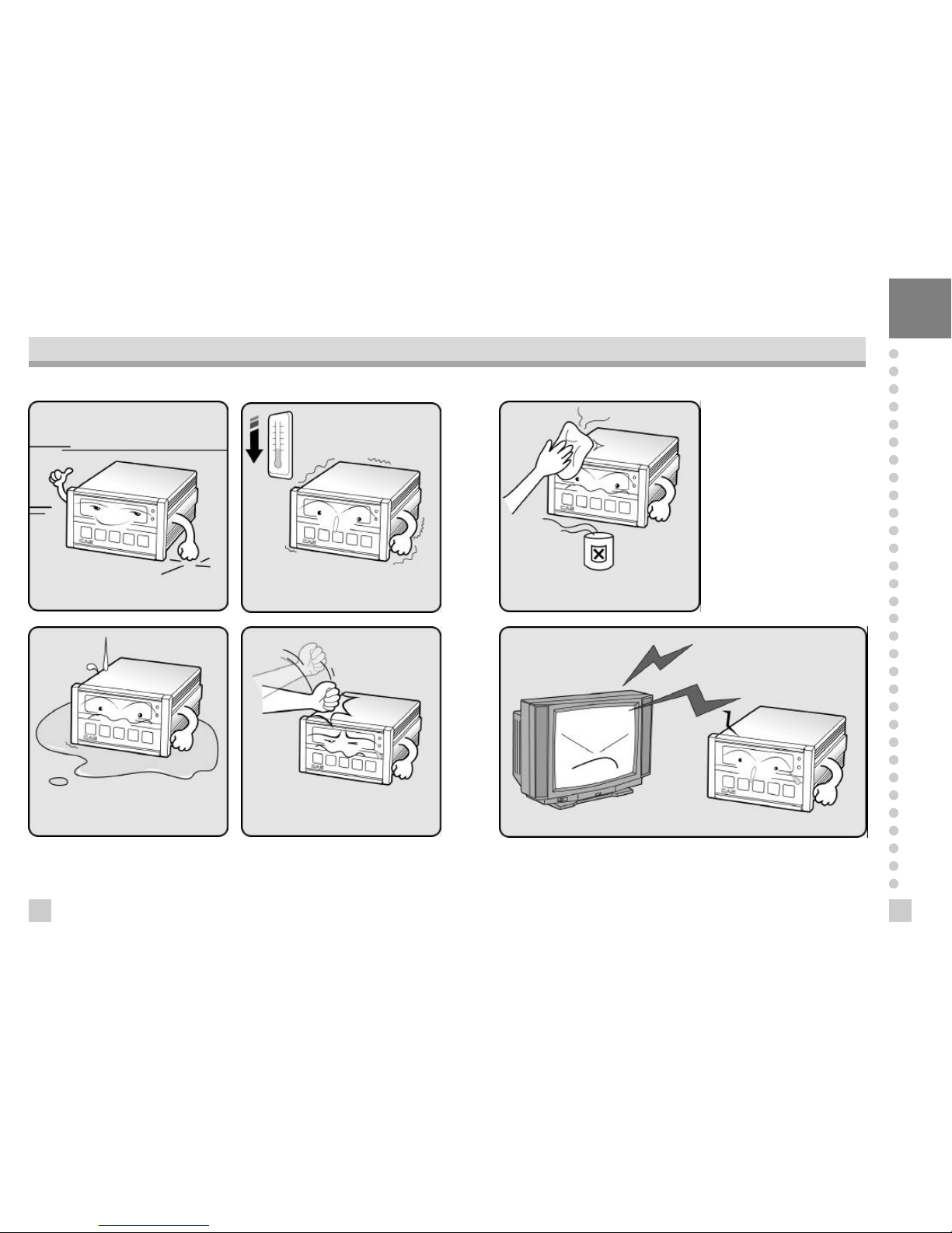
PRECATUTIONS
n Place the indicator on a flat and stable
surface.
n Do not subject the scale to sudden
temperature changes.
n This scale must be installed in a dry and
liquid free environment.
n Do not severely press because the light
pressing of keys can incite the operation.
n Do not use inflammable materials in
cleaning
n Keep the scale away from strong EM I noises may cause incorrect weight reading
Page 3
7
6
We greatly appreciate your purchase of the
CI-1500
weighing indicator. These goods
perform excellently and exhibit splendid prop erties through strike tests. CAS indicator
(CI-series) is delicately designed to coincide with the special requirements of several
industrial fields and includes many functions and various external interfaces. Also, it is
programmed for the user's convenience and contains help display functions that are
easily accessible.
Before using
CI-1500A Series
, It is recommended that you read this manual carefully so
you may use this device to its full potential.
INTRODUCTION
CI-1500/1560A FEATURES
1. Features
n
High quality, High accuracy
n
Appropriate for weight and measurement system
n
Easy operation and various options
n
Display of 6 digit( 7 Segment)
n
RFI/EMI screened
n
WATCHDOG circuitry (System restor ation)
n
WEIGHT BACK-UP ( Memory the weight at sudden power failure)
n
Store date, time and calculated data at sudden power failure
n
Adjustab le display rate(Digital filter function)
n
Tare weight setting with keys
n
Users can set maximum weight which users want to and division at one's disposal
n
Self test hardware function
n
Independ ent zero calibration
n
External Input/Output -(CI-1560A)
: 2 External Input - (zero, F08)
4 External Output - (zero, 1 Step, 2 Step, Final)
n
Serial pr inter connection
n
Print date and time by inner clock
2. Main Function
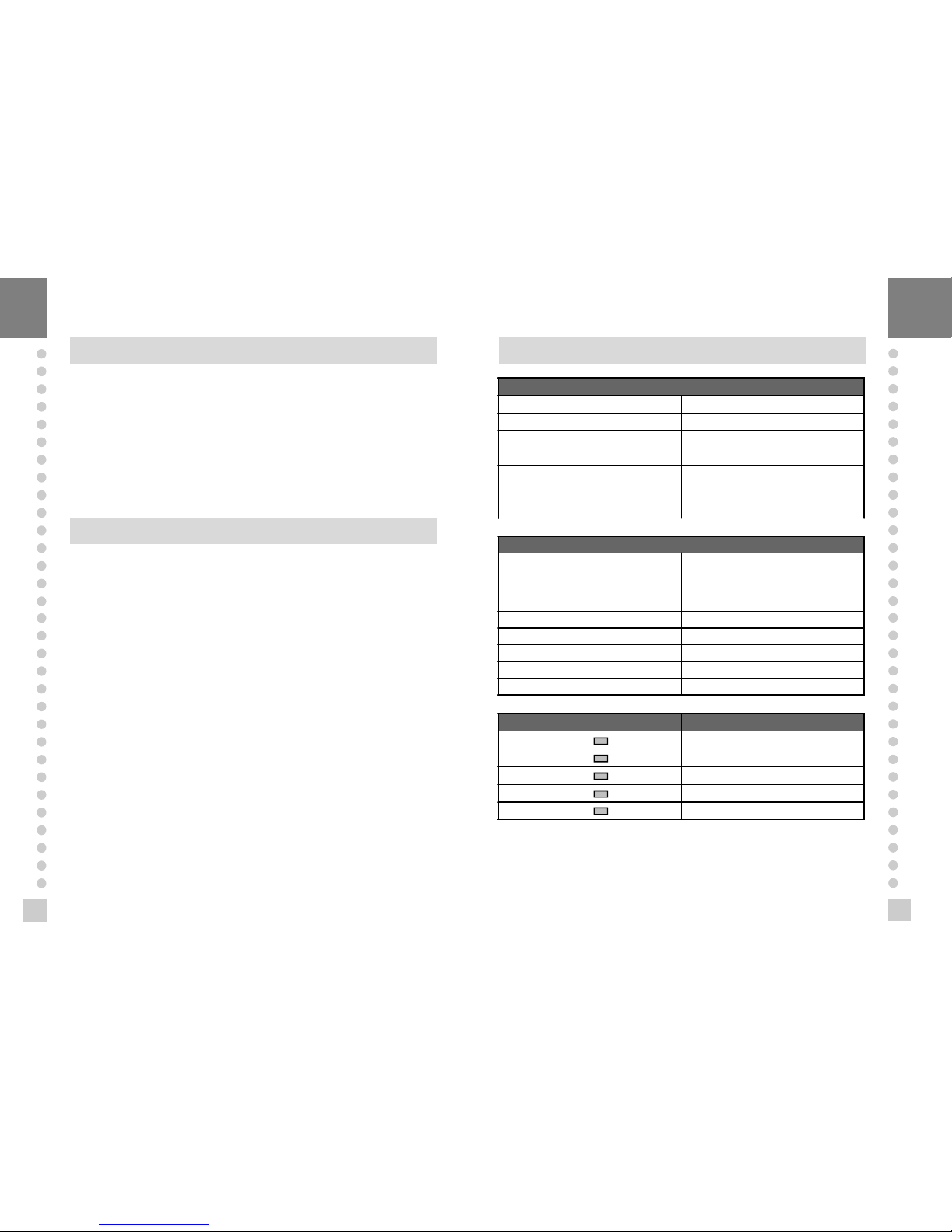
TECHNICAL SPECIFICATION
Analog Part & A/D Conversion
Load cell Excitation Voltage DC 5V
Zero adjust range 0.05 mV~30mV
Input Sensitivity over 1 μV/D
Nonlinearity 0.01% F.S.
A/D internal resolution 1/100,000
A/D external resolution 1/10,000(Max.)
A/D conversion speed 10 times/sec
Digital Part
Span Calibration
Full Digital Calibration
(Single pass automatic span calibration)
Input noise below 0.3 μVpp
Input impedance over 10
㏁
Display 7 Segment (6 digit)
Maximum Capacity 999999
Division x 2, x 5, x 10, x 20, x 50
Display below zero "-" minus signal
Permitted limit tare Full capacity
Lamp Description
" STABLE " LAMP Weight is stable
" TARE " LAMP Tare is used
" NET " LAMP ON(NET weight), OFF(GROSS weight)
" HOLD " LAMP Hold in Weight
" ZERO " LAMP "0" kg
±
Page 4

9
8
GENERAL SPECIFICATION
Power AC 220V, 50/60 Hz
Size 110(W) x 130(D) x 66(H)
Temperature -10℃~+40
℃
Weight Approx 750g
Power Consumption Approx 10W
MEASURE OF APPEARANCE
FRONT PANEL
1. Weight display Lamp
n
ST Lamp : turn on when the weight is stable.
n
TARE Lamp : turn on when tare weight is stored.
n
NET Lamp : turn on when the current weight is Net weight.
n
HOLD Lamp: turn on when the weight is held while weighing moving or alive things.
n
ZERO Lamp : turn on when the current weight is 0 kg.
2. Keyboard
Used to return the display to the 0.
User set the zero range within 4% or 10% of the maximum capacity(F09).
Used to enter the TEST mode.
Used to weigh item by using the container.
When this key is pressed, the scale stores current weight as the tareweight.
If you press TARE key in unload condition, tare setting is released.
Used to enter the SET mode.
Used to current value X 10 in CAL, SET mode.
Use this key to switch from GROSS to NET weight.
The annunciators and display will alternate between GROSS and NET aswell.
In case tare weight is REGISTERED, tare plus item's weight is GROSS weight
and only item's weight is NET weight.
When the Lamp turning on, it means NET weight.
Used to set current value+1 in CAL, SET mode.
When you press this key, the current designated printing form is printed.
Use this key when weighing data is printed.
Used to set the when weighing data is printed.
Used to set the current value - 1 in SET mode.
Used to store current condition and exit in CALIBRATION, TEST, SET mode.
Used to enter the CAL mode.
ZERO
TARE
3
NET
GROSS
5
3
PRINT
SET
Page 5
11
10
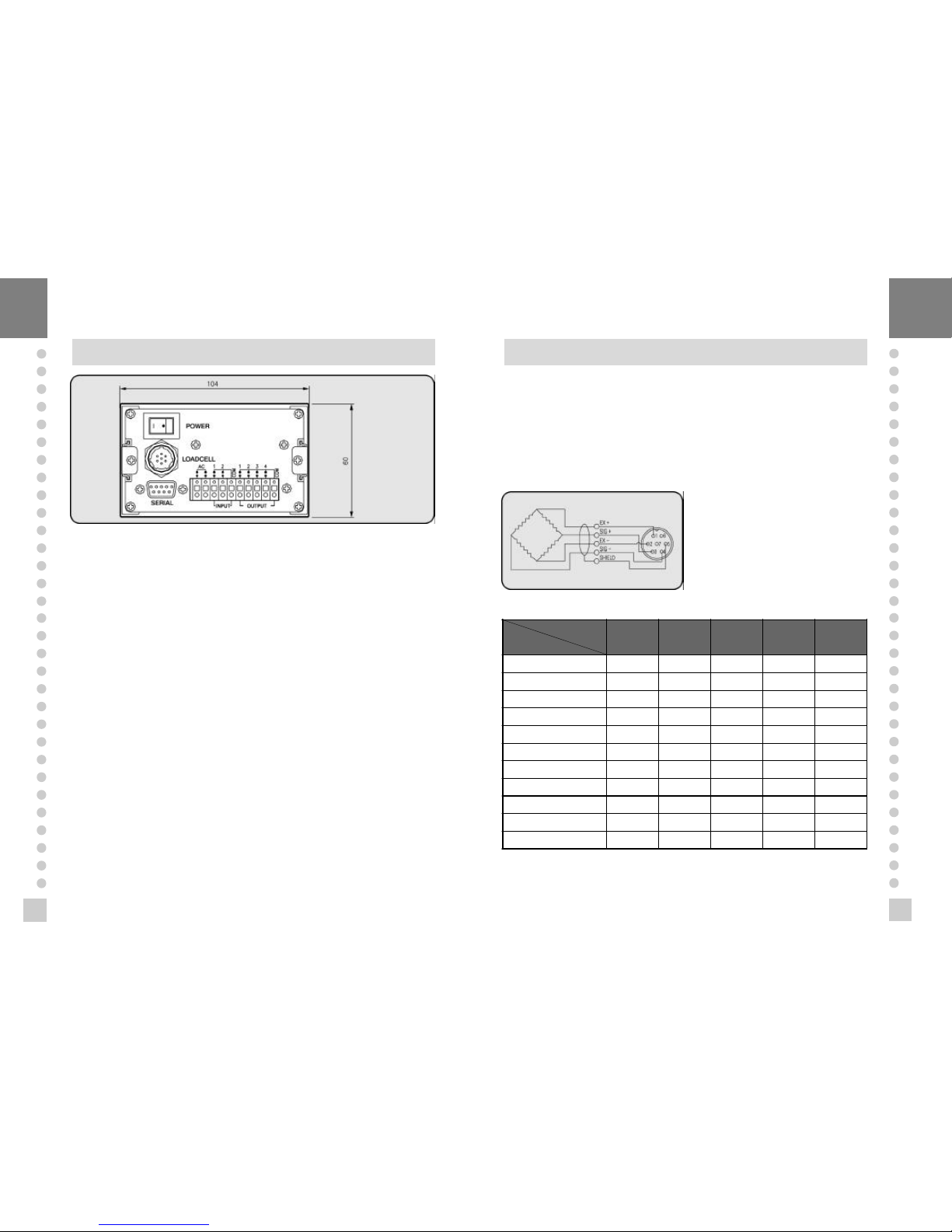
REAR PANEL
n
INPUT : External input
ZERO
key ,
START
key(F08)
n
OUTPUT : External output (relay output)
ZE RO, LOW, HIGH, FINAL
n
LOAD CEL L : Port for connecting load cell.
1: EX+ 2: EX- 3: SIG+ 4: SIG- 5: GND
n
POWER : POWER ON/OFF
n
AC : Only for 220V 50/60 Hz
n
SERIAL : RS-232C
INSTALLATION & CONNECTION
Load cell connection
Pin1: Excitation voltage+
Pin2: Excitation voltagePin3: Sense voltage+
Pin4: Sense voltagePin5: Shield
n
Connecting method
4Each L/C manufacturer’s or model’s
wire color could be differ ent. In that
case, please note the following
diagram.
n
Manufacturer’s wire color
Connector
Company
Pin 1
(EX +)
Pin 3
(EX - )
Pin 5
(SIG +)
Pin 6
(SIG - )
Pin 7
(SHIELD)
CAS RED WHITE GREEN BLUE CASE
KYOWA RED BLACK GREEN WHITE CASE
INTERFACE RED BLACK GREEN WHITE CASE
P.T RED BLACK GREEN WHITE CASE
BLS GREEN BLACK WHITE RED YELLOW
SHOWA RED BLUE WHITE BLACK CASE
SHINKOH RED BLACK GREEN WHITE CASE
TMI RED WHITE GREEN BLUE YELLOW
TML RED BLACK WHITE GREEN CASE
TFAC RED BLUE WHITE BLACK YELLOW
HUNTLEIGH GREEN BLACK RED WHITE CASE
Page 6
13
12
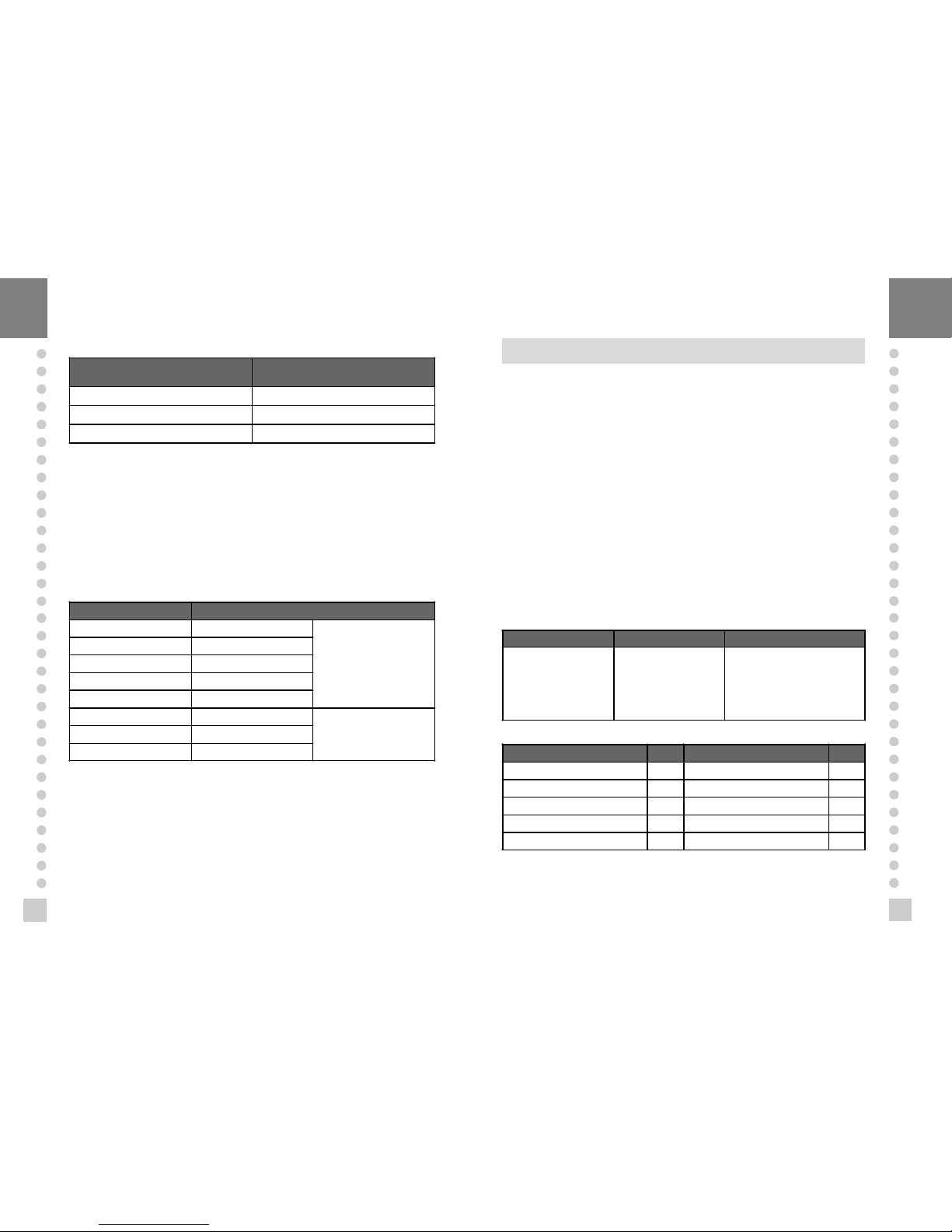
n
Resolution to load cell output rate
10V impression to load cell Max.
load cell output
Recommended resolution
2 mV 1/1,000(Max)
4 mV 1/2,000(Max)
8 mV 1/5,000(Max)
Connection to AC power
Connect to the AC power and turn the power switch on.
The Input Voltage is only for 220V 50/60 Hz
External input port connection
If you are away from CI-1500A and you want to control key , Please connect the
CI-1500A with
remote key
via rear panel.
External Output port connection (realy is 5W)
Multi Connector Relay
1 ZERO RELAY
REALY OUT-PUT
2 1 STEP(LOW RELAY)
3 2 STEP(HIGH RELAY)
4 FINAL RELAY
COM RELAY OUT-PUT COM
1 ZERO KEY
KEY IN-PUT2 START KEY(F08)
COM KEY IN-PUT COM
TEST MODE
n
How to enter
Turn on the power while pres sing the
ZERO
key on the front of the indicator.
4When test is done, Press
SET
key.
n
Availab le k eys
- Set key
:
Used for moving to the next test menu.
- Other keys : Used for changing the preset value.
n
Test Menu (TEST 1- TEST 6)
TEST 1 : Key test
TEST 2 : Disp lay test
TEST 3 : Load cell test and A/D conversion test
TEST 4 : Ser ial interface test
TEST 5 : Printer test
TEST 6 : External input/output tes t (CI-1560A)
TEST 1
KEY Display Description
SET : Move to nextmenu
Other keys : Perform test
Key number
ex) In case of Zero key
1
-Press the key to be test and
the No of key mode should be
indentify with code of key as
the follows
-If you press Set key. it will be
moved to test 2.
KEY NAME No EXTERNAL INPUT No
ZERO 1 IN 1 6
TARE, 2 IN 2 7
NET/GROSS, 3
PRINT, 4
SET 5
n
FUNCTION : KEY TEST
n
KEY LIST
3
5
6
Page 7

15
14
TEST 2
n
FUNCTION : Display test
KEY DISPLAY DESCRIPTION
SET : Move to next
menu
Other keys : Perform
test
- TEST 2 is perormed.
- After this test completing, it will be
moved to test 3 automatically
TEST 3
n
FUNCTION : A/D converter test
KEY DISPLAY DESCRIPTION
SET : Move to next
menu
ZERO KEY : Set the
current value to 0
Digital value of
current weight
ex) 1 5 0 0
- TEST 2 is perormed.
- After this test completing, it will be
moved to test 3 automatically
4Note 1. Check whether digital value is changing.
If the digital value is fixed or zero is displayed, please check the connection
of load cell.
TEST 4
n
FUNCTION : RS-232 test with computer (SERIAL port)
4 Note 1. Do this test after the connection of serial port of computer and serial port of
indicator is done.
Note 2. Send no.1 in computer keyb oard and check if indicator receives no.1
Send no.1 in indicator keyboard and check if computer receives no.1
Note 3. Do this test after baud rate is specified in
SET
mode and F03 is 2 in
SET
mode.
KEY DISPLAY DESCRIPTION
SET : to next menu
Other keys :
Transmitting key
Waiting for transmission and
reception
Transmitted : none, Received : 1
Transmitted : 1, Received : none
Transmitted : 1, Received : 1
※
INDICATOR TEST (When it isn’t connected with PC)
① Conect directly between No. 2(TXD) and No. 3(RXD) in indic ator of serial port.
② If transmitting data is identical with receiving data by pressing key of front panel,
this test will be done.
TEST 5
n
FUNCTION : Printer test (PRINTER)
KEY DISPLAY DESCRIPTION
SET : Move to next
menu
Other keys : Perform
test
No error in printer
Do this test after connection Serial
printer
4Note 1. Perform test only when the printer connection are installed.
Note 2. Pr eviously specify the printer which will be used in the conversion mode
Note 3. This test can be done under condition of 1 in F03.
Note 4. "
GOOD
" message is displayed if the printer connection and specification is
done corr ectly. If or not, "
ERR 6
" message is displayed.
Note 5. The test output format of printer is as the follows.
Only available if OPTION is installed.If or not, this test will be skipped and moved
to test 6
---------------- CI-1500A
http://www.cas.co.kr
TEST OK
-----------------
Page 8

17
16
TEST 6 (CI-1560A)
n
FUNCTION : External input/output (relay test)
KEY DISPLAY DESCRIPTION
SET : Move to next
menu
External key in external
input : Perform test
ZERO, TARE, N/G,
PRINT key in external
output : Perform test
Waiting for key and External input
out put : none, input : 1
out put : 1, input : none
out put : 1, input : 1
CALIBRATION MODE
1.How to enter
Turn on the power while pr essing
SET
key on the front of the indicator.
2. Available keys
- used to move to the next test menu.
- used to enter "Weighing mode".
used to set the current value to zero in CAL 1,3.
used to set the current value x 10 in CAL 1,3.
- used to set the current value +1 in CAL 1,3.
- used to increase one division value in CAL 2.
used to decrease one division in CAL 2.
※Calibration mode follow as these steps.
When you press
SET
key in CAL1, it is shifted to the next menu.
SET
key
SE T
key
SE T
key
AUTOMATIC
SET
key
SET
key
CAL 1 CAL 2 CAL 3 CAL 4 CAL 5 END Weighing mode
3. Calibration Menu (CAL 1- CAL 7)
CAL 1 :
Maximum Capacity Set
CAL 2 :
Minimum Division Set
CAL 3 :
Setting Weight in Span Calibration
CAL 4 :
Zero Calibration
CAL 5 :
Span Calibration
CAL 1
n
FUNCTIO N : Maximum Capacity Set
RANGE 8 1~ 999,999
KEY DISPLAY DESCRIPTION
SET key : store and into
next menu
ZERO key , , :
change the set value
t1. 00
CAL 1
Maximum capacity
value(ex:5000)
Program version
CAL 1 condition
5000 kg
4Note 1. The maximum capacity means the maximum weight that scale can measure.
Note 2. Do not input the resolution, there is no need to input the resolution
which is automatically calculated.
Note 3. If you press
SET
key, it will be moved to CAL 2.
CAL 2
n
FUNCTION : Minimum Division Set
RANGE 8 0.001~500
KEY DISPLAY DESCRIPTION
SET
key : store and
move into next menu
, :
change the set value
CAL 2
Minimum division
value(ex : 0.01
0.001)
CAL 2 CONDITION
0.01 kg
0.001 kg
4Note 1. The minimum division means the value of one division.
Note 2. External resolution is ob tained by dividing the min. division by the
maximum capacity . Set the resolution to be within 1/10,000.
Note 3. If you press Set key, it will be moved to CAL 3.
TARE
3
NET
GROSS
5
3
PRINT
SET
ZERO
◀ ▲
◀ ▲
Page 9

19
18
CAL 3
n
FUNCTION : Setting Weight In Span Calibration
RANGE 8 1~Maximum capacity of CAL 1
KEY DISPLAY DESCRIPTION
SET
key : store and
move into next menu
ZERO
key, , :
change the set value
CAL 3
Maximum capacity of
CAL1(ex:5000)
Setting weight(ex:500)
CAL 3 condition
5000 kg
500kg
4Note 1. The setting weight shall be within the range of 10 % ~100 % of maximum
weight.
Note 2. If the Setting Weight is under the 10% of the Maximum Capacity,
Error message
ERR 22
will occur.
Note 3. If the Setting Weight over the Maximum Capacity,
Error message
ERR 23
will occur.
Note 4. If you press Set key, it will be moved to tes t 4.
CAL 4
n
FUNCTIO N : Zero Calibration
KEY DISPLAY DESCRIPTION
SET key :
Zero calibration
CAL 5
LOAd
setting weight
checking - 333333
indicator 222222
111111
GOOd
Factor value
End
CAL 4 condition
Unload the tray and press SET
Display A/D Value
Under zero calibration
Zero calibration is completed.
The program moves into Span
calibrayion automatically.
4Note 1. If Zero calibr ation is done without any error, GOOD message is displayed
and program moves into CAL 5 automatically.
Note 2. If the zero value is too low, ERROR message
ERR 27
is displayed.
Note 3. If the zero value is too high, ERROR message
ERR 26
is displayed.
Note 4. Zero calibration can be done independently. If you press
ZERO
key instead
of
SET
key, zero calibration will perform.
CAL 5
n
FUNCTIO N : Span Calibration
4Note 1. If Span calibr ation is done without any error, GOOD message is
displayed. The weight of setting weight is displayed on VFD screen.
Check the weight.
Note 2. If the span value is low, Error message
ERR 24
is displayed.
If the span value is high, Error mes sage
ERR 25
is displayed.
In that case, calibrate with lower resolution.
Please check the span value to be res olution 4 in TEST 3.
Note 3. If y ou press
SET
key, it will be moved to NORMAL MODE.
KEY DISPLAY DESCRIPTION
SET key :
Span calibration
CAL 5
LOAd
setting weight
checking - 333333
indicator 222222
111111
GOOd
Factor value
End
CAL 5 condition
Load the weight which was set in
CAL 3
It is displayed the setting weight.
And then, press Set key.
Under span calibration.
Span calibration is completed.
Check whether the displayed
weight is same with setting
weight.
The weight converting constant
value
Calibration is completed.
Under this condition, release the
load.
◀ ▲
Page 10

21
20
SET MODE
1. How to enter
Turn on the power while pres sing the
TARE
key on the front of the indicator.
2. Available keys
used to save inputted value and exit to menu selection.
used to set the current value to zero
used to set the current value x10.
used to set the current value +1.
used to set the current value -1.
3. Set Value Conversion Menu
F01 Change of display unit
F02
SET
Key usage
F03 Serial port Usage
F04 Auto P rint Usage
F05 Speed control of weigh display
F06 Automatic zero condition set
F07 Weig ht backup function set
F08 External Input 2 Usage
F09
ZERO
key operation range set
F10 Device number
F11 Baud rate set
F12 Data set sent to Computer
F13 Hold type set
F14 Set Clock
F20 Relay mode (CI-1560A)
F01
Function Display Description
SET display
unit(0~1)
F01 0 Unit : kg
F01 1 Unit : ton
F02
Function Display Description
SET key usage(0~2)
F02 0 is Hold key
F02 1 is Total data print
F02 2 is Start key in relay mode
F03
Function Display Description
Serial Port usage
(0~2)
F03 0 Not Used
F03 1 Connection to Serial Printer
F03 2 Connection to P.C or RemoteDisplay
F04
Function Display Description
Automatic print(0~1)
F04 0
Manual print-whenever you press
the key, it will be printed.
F04 1
Automatic print-when the weight is
stable or you press the key, it will be
printed.
F05
Function Display Description
Speed control of
weighing display
(Digial filter function,
1~9)
F05 1 In high speed
F05 5 In normal speed
F05 9 Very slowly
4Note 1. Upon setting the automatic print, the print is carried out without
p ressing the print key when the weight is in stable state.
Note 2. It shall be in 1 of F03.
4Note . Adjust the sp eed variation of the weight on the scr een to be suitable
for the current us age.
F06
Function Display Description
Automatic zero
condition set(0~9)
F06 0 No compensation
F06 2
Compensation for gradual change
below two division for 3 seconds.
F06 9
Compensation for gradual change
below nine division for 3 sec.
TARE
3
NET
GROSS
5
3
PRINT
SET
ZERO
Page 11

23
22
F07
Function Display Description
Weight backup
(OFF, ON)
F07 0 weight backup is off
F07 1 weght backup is on
4Note 1. In case occurr ing sudden power failure, it can be memoried the moment
value by this function
Note 2. If the AC power is OFF sudd enly and weight backup is ON, the scale
recovers previous weight after the power is ON.
Note 3. On and Off are alternately displayed by pres sing the numeric keys.
F08
Function Display Description
External Input 2
Usage(0~3)
F08 0 Tare Key
F08 1 Print Key
F08 2 Hold Key
F08 3 Start Key in Realy Mode
4Note. This function is available to control in long disitance.
At this time, you can ad just key usag e fit for the purpose.
F09
Function Display Description
Zero key op
F09 0
4% : zero key opearation within 4%
of maximum weight
F09 1
10% : zero key opearation within
10% of maximum weight
4Note. This function is to set the range of initial zero value.
F10
Function Display Description
Device number
(Identifcation
number of each
indicator, 00~99)
F10 00 Device No. 00
F10 05 Device No. 05
4Note 1. This device number is the data demand ing signal in s erial communication.
Note 2. It shall be in 2 in F03.
F11
Function Display Description
Baud rate
(Unit of speed In
data transmission,
0~5)
F11 0 600bps(bit per second)
F11 1 1200bps
F11 2 2400bps
F11 3 4800bps
F11 4 9600bps
F11 5 19200bps
4Note. It shall be just in 2 of F03.
F12
Function Display Description
Data set send to
computer (0~3)
F12 0 No data out put
F12 1
Transmission in state of stable or
unstable
F12 2 Transmission only in stable state
F12 3
Transmission only when requiring
data
4Note 1. When the scale is shipped out, the setting value is 0.
Note 2. In case of setting 3 of F12, weighing data will be transmitted after receiving
one byte which is specified in F10
Note 3. It shall be just in 2 of F03.
F13
Function Display Description
Hold type set (0~2)
F13 0 Average Hold
F13 1 Peak Hold
F13 2 Sampling Hold
4Note. Average hold : Compute the average weight of oscillating weights.
Peak hold : Compute the maximum weight of oscillating weights.
Sampling hold: Compute the moment weight of os cillating weights.
F14
Function Display Description
Clock usage (0~1)
F14 0 Not using Clock
F14 1 Using Clock
Page 12

Display Description
step 1 How to input Hi value in set mode.
step 2 Display existing value.
step 3
As you press key 9 times, the
setting value makes 0.9 kg.
step 4
step 5
As you press key 2 times, the
setting value makes 90 kg.
step 6
step 7
If you press
SET
key, it will be moved
to next menu.
25
24
▲
◀
SET
※
When you select 1 of F14.
C1
Function Display Description
Set Year (00~99)
C1 99 Year : 1999
C1 00 Year : 2000
C2
Function Display Description
Set Day (00~12) C2 10 October
C3
Function Display Description
Set Day (00~31) C3 30 Day : 30
C4
Function Display Description
Set Hour (00~23) C4 15 P.M 3
C5
Function Display Description
Set Minute (00~59) C5 59 Minute : 59
C6
Function Display Description
Set Second (00~59) C6 39 Second : 39
F20
Function Display Description
RELAY MODE
USAGE (0~4)
F20 0 Not used
F20 1 Limit Mode
F20 2 Checker Mode
F20 3 Limit type Chcker Mode
F20 4 Packer Mode
※
You can set Lo, H - FALL, L - FALL value same as above.
n
HI, Lo, H - FALL, L - FALL
Function Display Description
Set Hi, Lo, H - FALL,
L - FALL value
100 100 kg
Function Display Description
Set Delay Time (0~9)
1 1 second
9 9 seconds
n
DELAY
▲
◀
Page 13

27
26
n
Limit Mode
(LOW limit) (HIGH limit)
0 kg 50 kg 100 kg
WEIGHT
RELAY
ZERO
(OUT RELAY 1)
ON
OFF
ON
OFF
ON
OFF
ON
OFF
ON
OFF
ON
OFF
ON
OFF
OFF
ON
LOW
(OUT RELAY 2)
HIGH
(OUT RELAY 3)
FINAL
(OUT RELAY 4)
4Note. When L-FALL and H-FALL ar e set,
Low limit relay will come ON (Weig ht = Lo - L-FALL).
High limit relay will come ON (Weig ht = HI - H-FALL).
n
Checker Mode
(LOW limit) (HIGH limit)
0 kg 50 kg 100 kg
WEIGHT
RELAY
ON
OFF
ON
OFF
ON
OFF
ON
OFF
ZERO
(OUT RELAY 1)
LOW
(OUT RELAY 2)
HIGH
(OUT RELAY 3)
FINAL
(OUT RELAY 4)
n
Limit Type Check er Mode
n
Paker Mode
(LOW limit) (HIGH limit)
0 kg 50 kg 100 kg
WEIGHT
RELAY
ZERO
(OUT RELAY 1)
LOW
(OUT RELAY 2)
HIGH
(OUT RELAY 3)
FINAL
(OUT RELAY 4)
relay on at
stable
Page 14
29
28
WEIGHING MODE
1.How to enter
Turn ON/OFF switch on and you will enter the WEIGHING Mode.
2. Key usage in Weighing mode
Return the display to the ZERO
Used to subtract the weight of container placed on the platform.
When this key is pressed, the scale stores current weight as the tare
weight. If you press
TARE
key in unload condition.
tare setting is released.
Toggle key between GROSS weight and NET weight. The annunciators
and display will alternate between GROSS and NET as well.
In case tare weight is registered, tare and item's total weight is G.
weight and only item's weight is N, weight.
Used to print thee print FORM you've chosen is
SET
Mode.
- Used as
START
key in relay mode. (under 2 of F02)
- Used to set total print. (under 1 of F02)
- Used as
HOLD
key. (under 0 of F2)
- Used to store current condition and exit in CALIBRATION, TEST,
SET mode.
3. Main Usage of CI-1500A/1560A (Example 1 - Example 6)
n
Example 1. Zero compensation
Display or Key On platform Description
step 1 Empty Zero point drift.
step 2
Press
ZERO
key when
the weight is stable.
step 3 Empty
ZERO Compensation; The
present value is returned the
display to the ZERO.
4Note 1. It shall be in zero range to 4% or 10% of maximum capacity in Set Menu of
F09.
Note 2. Non-ability in HOLD state of the weight.
Note 3. Non-ability in setting tare.
n
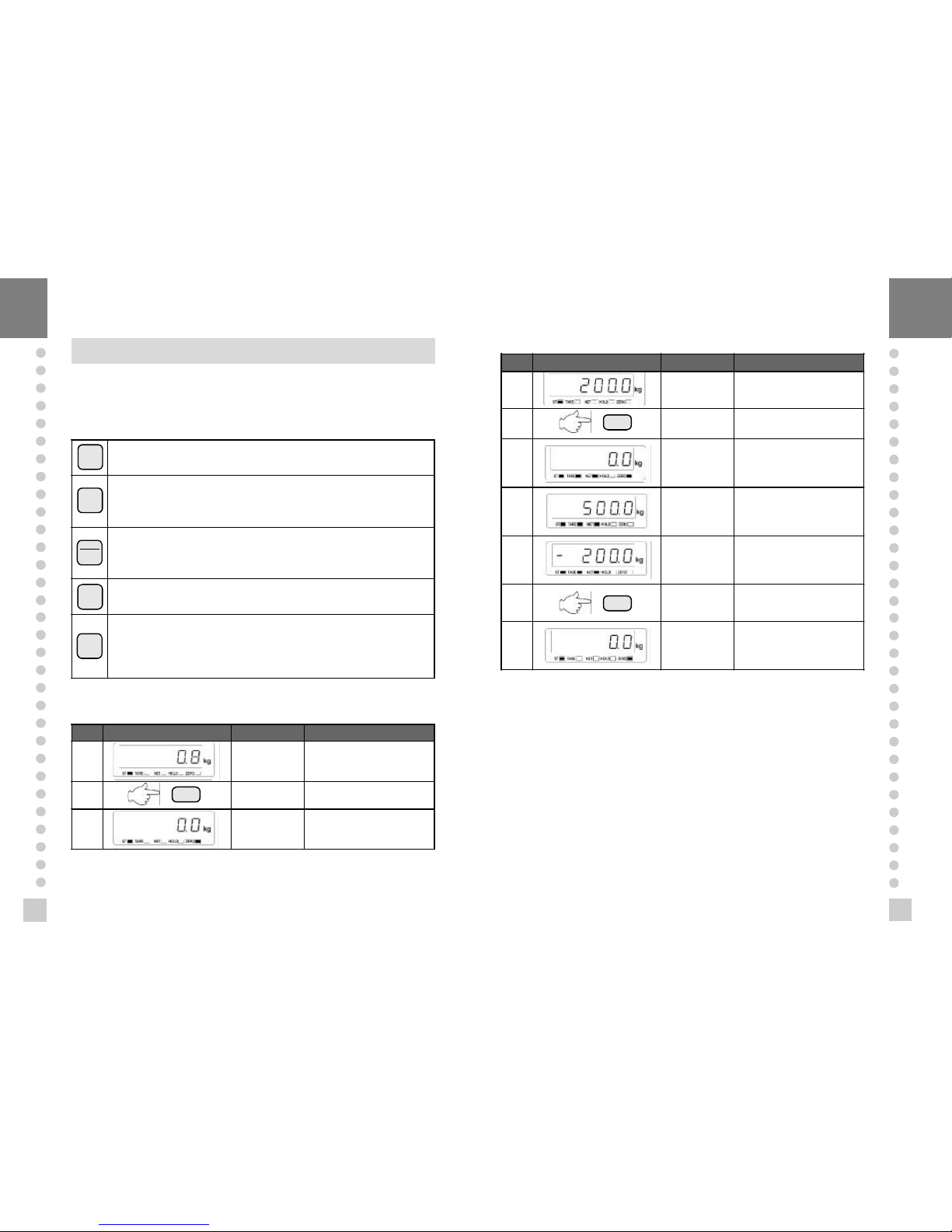
Example 2. Tare Function Usage
Display or Key On platform Description
step 1 Contaiiner Tare weight : 200kg
step 2
Store current weight as the
tare weight
step 3 Empty
To be turned on tare lamp
means that tare isregistered
in. Net Weight is on the
display
step 4
Container +
Content
Gross : 700kg
Net : 500kg
TARE
and
NET
key is
turned on.
step 5 Unload
Gross : 0.0kg
Net : -200.0kg
Tare function is turned on.
step 6 Unload
If you press
TARE
key in
unload condition, tare
setting is released.
Unload
Gross : 0.0kg
Net : 0.0kg
Tare function is turned off.
4Note. TARE Range maximum capacity.
Press
TARE
key when the weight is stable.
※
If you press TARE key in unload condition, tare setting is released.
TARE
3
NET
GROSS
5
3
PRINT
SET
ZERO
ZERO
TARE
TARE
Page 15

31
30
n
Example 3. To display NET or GROSS weight.
4Note. GROSS annunciator app ears when gross weight is on the display.
GROSS annunciator disappears when net weight is on the disp lay.
Display or Key On platform Description
step 1
Container and
Content (Article)
Article weight : 10.00kg
Tare weight : 5.00kg
Net weight is on the display
now.
step 2
step 3
Container and
Content (Article)
Gross weight is on the
display now.
stpe 4
step 5
Container and
Content (Article)
Net weight is on the display
now.
n
Example 4. To HOLD function (It shall be in 0 of F02)
Display or Key On platform Description
step 1 Article Weighing mode.
step 2 It shall be in 0 of F02.
step 3 Article
Hold weight is on the
display now.
step 4
If you press SET key in
loading condition, HOLD will
release.
step 5 Unload
When it is became
unloading condition, HOLD
will release automatically.
4Note 1. Choose HOLD type in SET menu (F13)
Average HOLD(F13 0): Compute the average weight of oscillating weights.
Peak HOLD(F13 1) : Choose the maximum weight among oscillating
weights.
Sampling HOLD(F13 2): Choose the current weight of oscillating weights.
Note 2. In case of using external input 2, it shall be in 2 of FO8.
n
Example 5. Print w eighing data (OPTION : It shall be in 1 of F03.)
Display or Key On platform Description
stpe 1 Article
step 2 Press PRINT key. (ref ①)
step 3 Article Weighing data is printed.
step 4 Press PRINT key. (ref ①)
step 5 Unload
step 6
Total data print (ref ②)
※It shall be in 1 of F02
1999. 09. 29 16:35:25
001, 1500kg 16:35:25
002, 1600kg 16:40:35
003, 1400kg 16:45:45
----Total Print -----
1999.09.29 16:35:25
Count: 003, 1500 kg
-----------------
①
Weighing data print format
②
Total data print format
NET/GROSS
NET/GROSS
SET
SET
PRINT
PRINT
SET
Page 16

33
32
RS-232C INTERF ACE/CLOCK
Transmit mode : RS-232C interface
n
Type : EIA - RS - 232C
n
Method : Full-duplex, asynchronous transmission Fomat
F11 Baud rate 600, 1200, 2400, 4800, 9600, 19200
F12 Output mode stable, Unstable, Data is required
①
Baud rate : 600 bps - 19200 bps
Choose Baud rate in SET mod e (F11).
Refer to SET mode.
②
Data bit : 8, Stop bit : 1, Par ity blt : None
③
Code : ASCII
④
When data is sent to computer ?
Set in SET mode (F12).
⑤
Data Fomat
, , , DATA (8 byte) K G CR LF
US (unstable)
ST (stable)
OL (over load)
GS (gross)
NT (net)
Device ID
Lamp status b yte Blank
※
Simple communication program (BASIC)
10 OPEN "COM1:9600,N,8,1" As #1
20 IF L OC(1) = 0 THEN 60
30 A$ = INPUT$(1,1)
40 PRINT A$ ; " ";
50 GO TO 20
60 B$=IN KEY$ : IF B$ ="" THEN 20
70 PRINT B$ ; " ";
80 PRINT #1,B$;
90 GO TO 20
※
Simple communication program (C)
#includ e <bios.h>
#include <conio.h>
#define COM1 0
#define DATA_READY 0x100
#define TRUE 1
#define FALSE 0
#define SETTINGS ( 0x80 | 0x03 | 0x00 | 0x00)
int main(void)
{
int in, out, status, DONE = FALS E;
bioscom(0, SETTINGS, COM1);
cprintf("... BIOSCOM [ESC] to exit ...\n");
while (!DONE)
{
status = bioscom(3, 0, COM1);
if (status & DATA_RE ADY)
if ((out = bioscom(2, 0, COM1) & 0x7F) != 0)
putch(out);
if (kbhit())
{
if ((in = getch()) == '\x1B') DONE = TRUE;
bioscom(1, in, COM1); }
}
return 0;
}
Page 17
35
34
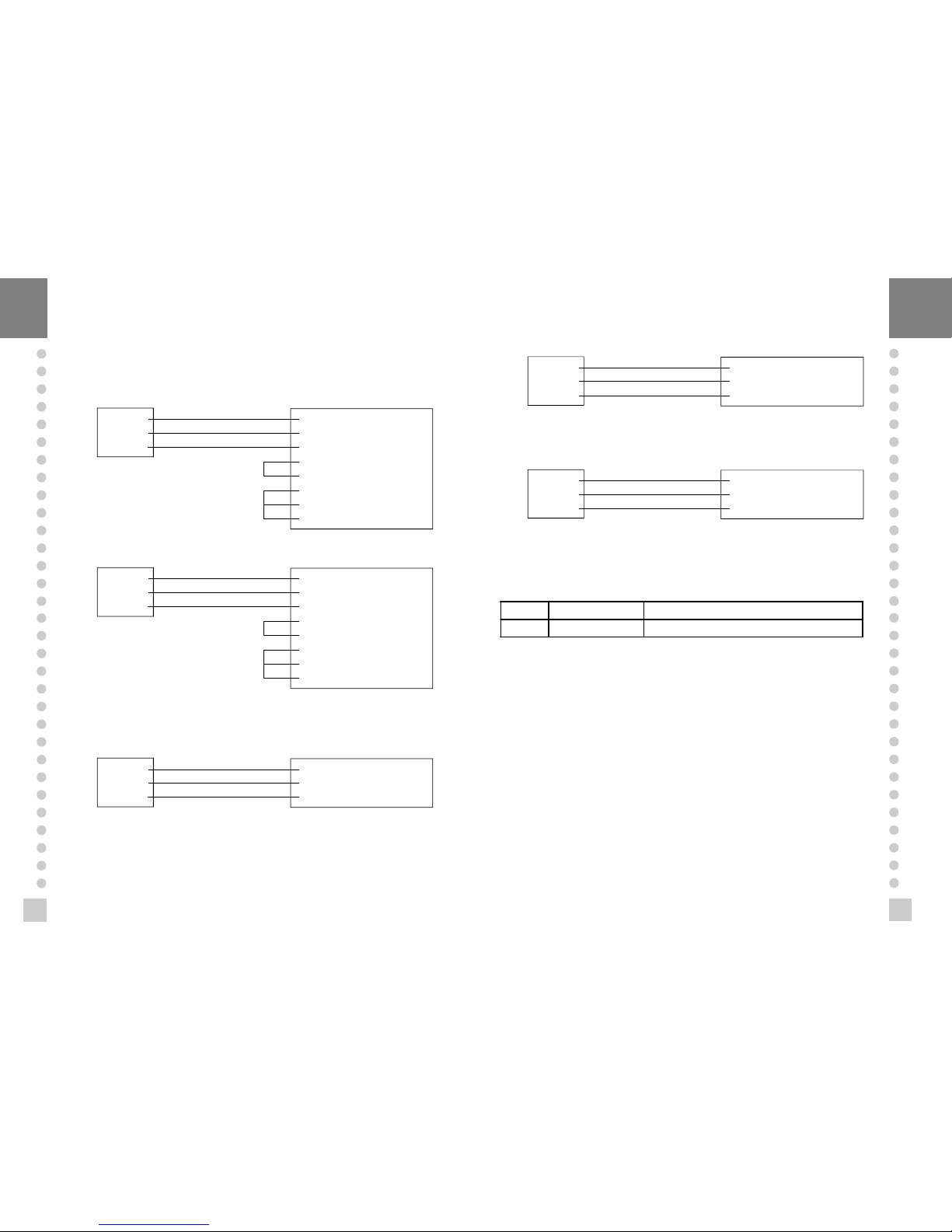
RS- 232C Port Connection
n
RS 232C port connec tion to PC
Connect SERIAL port on the rear panel of the indicator to serial port of PC as the
follows.
RXD 3 ㅇ
TXD 2 ㅇ
GND 7 ㅇ
ㅇ 2 Transmit Data
ㅇ 3 Receive Data
ㅇ 7 Signal Ground
ㅇ 4 Request To Send
ㅇ 5 Clear To Send
ㅇ 6 Data Set Ready
ㅇ 8 Carrier Detect
ㅇ 20 Data Terminal Ready
9 pin port (Male)
RS-232C port of CI-1560A
25 pin port (Female)
Serial port of computer
RXD 3 ㅇ
TXD 2 ㅇ
GND 7 ㅇ
ㅇ 3 Transmit Data
ㅇ 2 Receive Data
ㅇ 5 Signal Ground
ㅇ 1 Carrier Detect
ㅇ 4 Data Terminal Ready
ㅇ 6 Data Set Ready
ㅇ 7 Request to Send
ㅇ 8 Clear to Send
9 pin port (Male)
RS-232C port of CI-1560A
9 pin port (Female)
Serial port of computer
n
Sub - display connection
RXD 3 ㅇ
TXD 2 ㅇ
GND 7 ㅇ
ㅇ 2 Transmit Data
ㅇ 3 Receive Data
ㅇ 7 Signal Ground
9 pin port (Male)
RS-232C port of CI-1500A
9 pin port (Male)
RS-232C port of sub-display
RXD 3 ㅇ
TXD 2 ㅇ
GND 7 ㅇ
ㅇ 9 Transmit Data
ㅇ 5 Receive Data
ㅇ 1 Signal Ground
n
CAS TOP printer connection ( P-202)
9 pin port (Male)
RS-232C port of CI-1500A
9 pin port (Male)
TOP printerf of P-202 port
n
CP - 7000 Series printer connection
RXD 3 ㅇ
TXD 2 ㅇ
GND 7 ㅇ
ㅇ 2 Transmit Data
ㅇ 3 Receive Data
ㅇ14 Signal Ground
9 pin port (Male)
RS-232C port of CI-1500A
9 pin port (Male)
Serial printer of CP-7000 port
Clock
n
Connect serial port on rear panel of indicator to serial printer.
F14 Clock usage 0 : unused 1 : used
CI - 6 Set date and time yy, mm, dd, hh, mm, ss
Page 18

3736
n
Reason
The display weight is larger than the Maximum Capacity you’ve set.
n
Trouble shooting
Don’t load the article whose weight is larger than the Max. Capacity on the platform
scale. This may damage Load Cell.
(2) In CAL Mode
ERR 21
n
Reason
Resolution (Maximum Capacity ÷ Minimum Division) is over the limit (1/10,000).
n
Trouble shooting
Lower the resolution in one of the below ways.
① Modify Maximum Capacity in CAL 1 of Calibration Menu.
② Modify Minimum Division in CAL 2 of Calibration Menu.
ERROR MESSAGE & TROUBLE SHOOTING
(1) In Weighing Mode
ERR 02
n
Reason
Load cell connection failure or error in A/D conversion part.
n
Trouble shooting
Check the Load Cell connector to see if the polarity of signal is reversed.
ERR 13
n
Reason
Zero range deviate from the set range.
n
Trouble shooting
Confirm that there is nothing on the weighing platfor m.
If nothing exist, do Calibr ation in CAL mode.
ERR 22
n
Reason
Setting weight is set under 10% of the Maximum Capacity.
n
Trouble shooting
Set span setting weight equal to or over 10% of the Maximum Capacity in CAL 3 of
CAL Menu.
OVER
ERR 24
n
Reason
Load Cell output Volltage is too low at span Calibration.
ERR 25
n
Reason
Load Cell output Volltage is too high at span Calibration.
 Loading...