

Cary Audio Design HD1080P, HD720P User Manual

o o o o o o o o o o o o o o o o o o o o o o o o o o o o o o o o o o o o o o o o o o o o o o o o o o o o o o o o o o o o o o o o o o o o o o o o o
DVD 7
HD720P & HD1080P OUTPUT DVD Player
OWNER’S MANUAL
NOTE: Before installing your new DVD 7 player, please read this manual carefully
as it will inform you of the product specications, proper installation and correct
operating procedures for your unit. Also included in this manual are guidelines
on how to service and care for your new Cary Audio Design product.

TABLE OF CONTENTS
Important Safety Instructions .............................................................. 2
Welcome
Thank You ................................................................................................... 5
Product Features .......................................................................................... 5
Unpacking and Installation .......................................................................... 6
Format Playback Compatibility ..................................................................... 6
Specifications
Video Specifications ..................................................................................... 7
Audio Specifications ..................................................................................... 7
Digital Audio Output Specifications ...............................................................8
Making Connections
Before Connecting ....................................................................................... 9
Connections to a TV ..................................................................................... 9
Optional Video Connections ......................................................................... 9
Optional Audio Connections ....................................................................... 10
Controls & Displays
Front Panel ................................................................................................ 11
Rear Panel .................................................................................................. 13
The Remote Control ................................................................................... 15
Getting Started
Switching On .............................................................................................. 16
Using the On-Screen Displays .................................................................... 16
Changing Settings to Match your TV ......................................................... 16
Changing the Default Settings
Choose the SETUP menu ........................................................................... 18
Video Setup ................................................................................................ 18
Audio Setup ............................................................................................... 22
Disc Setup .................................................................................................. 24
Progressive Setup ...................................................................................... 27
AV Sync Setup ........................................................................................... 29
Playback
Starting a Disc ........................................................................................... 30
Stopping Playback ...................................................................................... 30
Pausing Playback ....................................................................................... 31
Forward/Reverse Searching ....................................................................... 31
Skipping to the Beginning of Chapters or Tracks
Playing Frame by Frame ............................................................................ 32
Selecting the Still Image ............................................................................ 32
Playing Bonus Groups ................................................................................ 32
Service and Care
Care and Cleaning ..................................................................................... 33
Factory Service .......................................................................................... 33
Non-Warranty Repairs ............................................................................... 33
United States Limited Warranty .......................................................... 34
....................................... 31
1

IMPORTANT SAFETY INSTRUCTIONS
WARNING: To reduce the risk of fire or electric shock, do
not expose this appliance to rain or moisture. The li g htning
flash with arrowhead symbol within an equilateral triang le i s
intended to alert the user to the presence of un-insulated
dangerous voltage within the product’s enclosure that may
be of sufficient magnitude to constitute a risk of electric
shock to persons.
CAUTION: To reduce the risk of electric shock, do not remove the cover. There are no user serviceable parts inside.
Please refer to qualified personnel for service.
ALERT: The exclamation point within an equilateral triangle is intended to alert the user of the presence of important
operating and maintenance (servicing) instruction s in the literature accompanying the component.
1. READ ALL INSTRUCTIONS: All the safety and operating instructions of your Cary Audio equipment should be read
before power is applied to the equipment.
2. RETAIN OWNER'S MANUAL: These safety and operating instructions should be retained for future reference.
3. HEED WARNING: All warnings on the unit and in the operating instructions should be adhered to.
4. FOLLOW INSTRUCTIONS: All operating and use instructions should be followed.
5. CLEANING: Unplug the unit from the wall outlet before cleaning. The unit should be cleaned only as recommended
by the manufacturer.
6. ATTACHMENTS: Do not use attachments not recommended by the unit manufacturer as they may cause hazards.
7. WATER AND MOISTURE: Do not use the unit near water - for example, near a bath tub, wash bowl, kitchen sink,
or laundry tub; in a wet basement; or near a swimming pool.
8. ACCESSORIES: Do not place the unit on an unstable cart, stand, tripod, bracket, or table. The unit may fall,
causing serious injury to a child, an adult, or da m a ge to the unit. Mounting of the unit should follow the
manufacturer's instructions and should use a mounting accessory recommended by the manufactur er.
9. VENTILATION: Slots and openin g s in the cabinet are provided for ventilation to ensure reliable operation of the
unit and to protect it from overheating. These openings must not be blocked or covered. The top or bottom panel
openings should never be blocked by placing the unit on a bed, sofa, rug, or other similar surface. The unit should
not be installed in a built-in location such as a bookcase or rack unless proper ventilation is provided. There should
be free space of at least 6 inches (16cm) above the unit and an opening behind the unit.
10. GROUNDING OR POLARIZATION: The unit may be equipped with a polarized alternating current line plug (a
plug having one blade wider than the other). This plug will fit into the power outlet only one way. This is a safety
feature. If you cannot insert the plug fully into the outlet, try reversing the plug. If the plug should fail to fit, contact
a licensed electrician to replace your obsolete ou tlet. Do not defeat the safety purpose of the polarized plug.
11. POWER SOURCES: The unit should be operated only from the type of power source indicated on the marking
label. If you are not sure of the type of power supplied to your home, consult your unit dealer or local power
company.
12. POWER CORD PROTECTION: Power supply cords should be routed so that they are unlikely to be walked on or
pinched by items placed on or against them. Pay close attention to cords where they enter a plug, or a convenience
receptacle, and the point where they exit from the unit.
13.
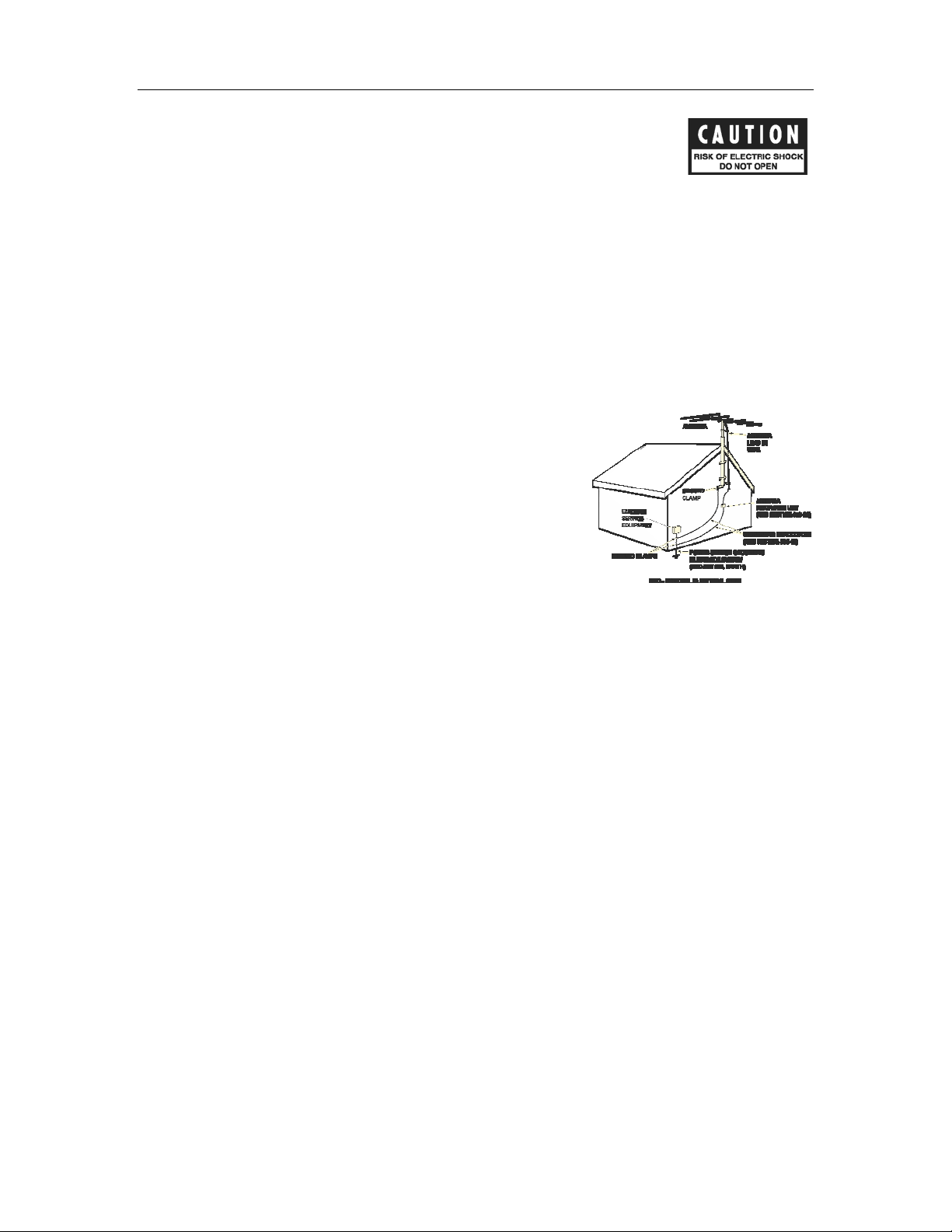
OUTDOOR ANTENNA GROUNDING: If an outside antenna or cable system is connected to the unit, be sure the
antenna or cable system is grounded so as to provide protection against voltage surges and built-up static charges.
Article 810 of the National Electrical Code, NSI/NFPA 70, provides information regarding proper grounding of the
mast and supporting structure, grounding of the lead-in wire to an Antenna-discharge unit, size of grounding
conductors, location of antenna-discharge u nit, connection to grounding electrodes, and requirements for the
grounding electrode.
2

IMPORTANT SAFETY INSTRUCTIONS
14. LIGHTNING: For added protection for the unit during a lightning storm, or when it is left unattended and unused
for long periods of time, unplug it from the wall outlet and disconnect the antenna or cable system. This will prevent
damage to the unit due to lightning and power line surges.
15. POWER LINES: An outside antenna system should not b e located in the vicinity of overhead power lines or other
electric light or power circuits, or where it can fall into such power lines or circuits. When installing an outside
antenna system, take extreme care to keep from touc hing such power lines or circuits as contact with them might be
fatal.
16. OVERLOADING: Do not overload wall outlets, extension cords, or integral convenience receptacles as this can
result in a risk of fire or electric shock.
17. OBJECT AND LIQUID ENTRY: Never push objects of any kind into the unit through openings as they may touch
dangerous voltage points or short-out parts that could result in a fire or electric shock. Never spill liquid of any kind
on the unit.
18. SERVICING: Do not attempt to service the uni t yourself as opening or removing covers may expose you to
dangerous voltage or other hazards. Refer all servicing to qualified service personnel.
19. REPLACEMENT PARTS: When replacement parts are required, be sure the service technician has used
replacement parts specified by the manufacturer or have the same characteristics as the original part. Unauthorized
substitutions may result in fire, electr ic shock or other hazards.
20. SAFETY CHECK: Upon completion of any service or repairs to the unit, ask the service technician to perform safety
checks to determine that the unit is in proper operating condition.
21. WALL OR CEILING MOUNTING: The unit should be mounted to a wall or ceiling only as recommended by the
manufacturer.
22. HEAT: The unit should be situated away from heat sources such as radiators, heat registers, stoves, or other units
(including amplifiers) that produce heat.
23. IMPORTANT SAFETY NOTE: Before c onnecting a new component such as the DVD 7 to your audio or home
theater system it is always good practice to make certain that all components are turned off, and preferably
unplugged from their AC power source. Many modern electronics products feature automatic turn-on circui ts that
may be activated during an installation, causing the potential for damage to electronic components and/or speakers.
Such damage is not covered by product warranties and Cary Audio specifically disclaims responsibility for any such
damage.
Power Cord: The removable power cord that is shipped with the player is specifically designed to be used with this
product. Other AC cords may be used, so consult your dealer for advice on AC power cords and high quality wire in
your system.
Wiring: Cables that run inside of walls should have the appropriate markings to indicate compliance with, and listing
by the UL, CSA or other standards required by the UL, CSA, NEC or your local building code. Questions about cables
inside of walls should be referred to a qualified custom installer, or a licensed electrician or low-voltage contractor.
Do Not Open the Cabinet: There are no user serviceable components inside this product. Opening the cabinet
may present a shock hazard, and any modification to the product will void your warranty. If water or any metal
object, such as a paper clip, coin, or staple accidentally falls inside the unit, disconnect it from the AC power source
immediately and contact Cary Audio for further instructions.
24. RECORDING COPYRIGHT:
permission of the copyright holder.
25. NOTE TO CATV SYSTEM INSTALLER: This reminder is provided to call the CATV system installer's attention to
article 820-40 of the NEC, ANSI/NFPA 70, which provides guidelines for proper grounding and, in particular, specifies
that the cable ground shall be connected to the grounding system of the building, as close to the point of cable entry
as practical.
AC Fuse: The fuse is located inside the chassis and is not user serviceable. If power does not
come on, contact your authorized service representative.
Recording of copyrighted material for other than personal use is illegal without
3
IMPORTANT SAFETY INSTRUCTIONS
26. FCC INFORMATION FOR USER:
CAUTION: ANY changes or modifications not expressly approved by the party responsible
for compliance could void the user's authority to operate the equipment.
NOTE: This equipment has been tested and found to comply with the limits for a Class B digital device pursuant to
Part 15 of the FCC Rules.
These limits are designed to provide reasonable protection against harmful interference in a residential installa tion.
This equipment generates and can radiate radio frequency energy and, if not installed and used in accordance with
the instructions, may cause harmful interference to radio communications. However, there is no guarantee that
interference will not occur in a particular installation. If this equipment does cause harmful interference to radio or
television reception, which can be determined by turning the equipment off and on, the user is encouraged to try to
correct the interference by one or more of the following measures:
- Reorient or relocate the receiving antenna.
- Increase the separation between the equipment and receiver.
Connect the equipment into an outlet on a circu it different from where the receiver is connected.
27. OUTDOOR ANTENNA INSTALLATION/SAFE ANTENNA AND CABLE
CONNECTION: If an outside antenna or cable system is connected to
the equipment, be sure the antenna or cable system is grounded so as to
provide protection against built up static charges and voltage surges,
Section 810 of the national Electrical Code, ANSI/NFP A70 (in Canada,
part 1 of the Canadian Electrical Code) provides information with respect
to proper grounding of the mast and supporting structure, grounding of
the lead-in wire to an antenna discharge unit, size of grounding
conductors, location of antenna discharge unit, connection to grounding
electrodes and requirements for the grounding electrode.
Keep Antenna Clear of High Voltage Power Lines or Circuits
An outside antenna system should be located well away from power lines, electric light or power circuits and where
it will never come into contact with these power sources if it should happen to fall. When installing an outsid e
antenna, extreme care should be taken to avoid touching p ow e r li nes, circuits or other power sources as this could
be fatal. Because of the hazards involved, anten na installation should be left to a professional.
4

WELCOME
THANK YOU
Dear Customer:
We would like to thank you for your decision to buy a Cary Cinema DVD 7 player. The DVD 7 is
one of the best DVD players available on the market today and we expect that you will enjoy
your cinematic home experience for years to come. The DVD 7 player is a continuance and
elevation of the DVD 6 player which met and exceeded customer expectations time and time
again. The DVD 7’s craftsmanship, forward thinking design, and flexibility make it a desirable
component for all video lovers, integrating well with existing home theater setups and new
designs alike.
Thank you for your support and enjoy your movies!
The Cary Audio Team
PRODUCT FEATURES
The DVD 7, our third generation DVD player, is assembled with the best available components. It
is an innovative design of the highest quality. The DVD 7 player provides video outputs from 480i
to as high as 1080p with HDMI, RGB + HV or Component video outputs. This truly unique feature
is compatible with either HD or ED video displays. The audio soundtrack playback quality
matches the vibrancy and vividness of the video output from the
processor section.
The DVD 7 offers:
• Video outputs from 480i to as high as 1080p with HDMI, RGB + HV or Component video
outputs
• Rugged steel chassis
• Industrial grade DVD CD ROM drive mechanism
• Fiberglass PCBs
• 1% precision parts
• Fully regulated power supplies
• Steel tunnel shielded drive mechanism
• Discrete commands for RS 232 and infra red codes for remote control
The DVD 7 player has 3 completely separate
the linked HDMI or RGB video outputs at a display setting of 480p/576p to as high as 1080p at
the same time and same setting. Simultaneously, you can use the Component video outputs at
an independent setting of 480i, 480p, 720p, 1080i or 1080p. The S-Video or the composite video
outputs can run 480i at the same time. If they are all the same aspect ratio, this player can be
the video source for 3 to 6 displays at the same time.
The DVD 7 is also unique because it offers audio playback quality beyond compare. The audio
section of the DVD 7 is derived from the CD 303/300, which was named the “2005 Product of the
Year” by Electronic House magazine. The DVD 7’s sound quality rivals audiophile CD players at
any price point.
ALWAYS ACTIVE
ALWAYS ACTIVE
video output sections. You can run
triple video
5

WELCOME
UNPACKING AND INSTALLATION
This section describes the unpacking and installation procedures for your new component.
Unpacking
All Cary Audio Design shipping cartons have been specially designed to protect their contents and
special care has been taken to prevent damage under normal shipping conditions. Mishandling
should be evident upon inspection of the shipping container. If shipping damage is found after
visual inspection, take care not to destroy the evidence. If necessary, document the damage with
photographs and contact the transport carrier immediately.
Carefully remove your new component from its packing carton and examine it closely for signs of
shipping damage. We strongly recommend saving all original packing cartons to protect your
component from damage should you wish to store it or ship it at a later date.
In the Box
When unpacking your DVD 7 player, make sure the following accessories are included. You
should find the following items:
• Power Cable
• Remote Control (batteries already installed)
• Owner’s Manual
• Warranty Card
Warranty Card
If you are the original purchaser of this unit and you purchased it in the United States, you
should fill out the enclosed warranty registration card and return it to Cary Audio Design within
15 days of your purchase. Cary Audio Design also suggests that you keep your original packing
cartons in case you ever need to ship the unit when moving to a new home. Warranty
restrictions apply. Consult the warranty section of this manual for details. Please be certain to
keep a copy of the original sales receipt from your Authorized Cary Audio Design dealer to
validate the warranty if ever needed.
FORMAT PLAYBACK COMPATIBILITY
The Cinema DVD 7 can play CD, Video CD, DVD Video, DVD-R, DVD+RW and CD-RW disks.
It incorporates technology from Dolby Laboratories
Division of Genesis Microchip and the High Definition Multimedia Interface.
*All trademarks belong to their original owners.
®
, Digital Theater Systems®, Faroudja®, a
6

SPECIFICATIONS
Operating the DVD 7 player is a simple procedure. Each unit is designed for long term stability in
virtually any home operating situation. However, if the unit is operated outside the parameters
outlined in this owner's manual, damage may result. Please read this manual carefully before
putting your new DVD 7 player into operation.
The following section describes the DVD 7 players’ basic specifications. The specifications are
subject to change without notice or obligation.
VIDEO SPECIFICATIONS
...........................................................................................................................................................................
Playback System DVD Video / Video CD / CD / DVD-RW / DVD+RW / CD-RW
...........................................................................................................................................................................
Video DAC chips Dual Faroudja Video Format
HDMI/RGB/CV Converter/HDMI
(3 Video chip sets)
12 bit/108 mHz Component Video (CV)
...........................................................................................................................................................................
Video S/N Ratio 78.5 dB
...........................................................................................................................................................................
Video Signal Resolution 540 TV Lines (DVD)
...........................................................................................................................................................................
Signal Format System PAL / NTSC
...........................................................................................................................................................................
Composite Video Output 1.0 volt peak to peak (75 Ohm), Sync Negative
...........................................................................................................................................................................
S-Video Luminance Signal: 1 volt peak to peak (75 Ohm load)
Color Signal: 0.286 volt peak to peak (75 Ohm load)
...........................................................................................................................................................................
Interlaced and Progressive Y Output Level: 1.0 volt peak to peak (75 Ohm load)
Component Video Output Pb Output Level: 0.7 volt peak to peak (75 Ohm load)
...........................................................................................................................................................................
Progressive Component 480p/576p, 720p, 1080i, 1080p
Output Settings
...........................................................................................................................................................................
Interlaced Video Outputs 480i - Component, S-video and Composite Video
...........................................................................................................................................................................
HDMI/RGB 480p/576p, 720p, 1080i, 1080p, 600x800, 1024x768,
Output Settings 1280x1024, 1366x768
...........................................................................................................................................................................
AUDIO SPECIFICATIONS
...........................................................................................................................................................................
Master Clock Jitter Below measurable levels
...........................................................................................................................................................................
Digital/Analog Converters Burr Brown PCM 1792u
...........................................................................................................................................................................
Analog Filter Third Order Bessel
...........................................................................................................................................................................
Analog Outputs RCA, XLR stereo
Dual 12 bit/216 MHz/RGB
Pr Output Level: 0.7 volt peak to peak (75 Ohm load)
7

SPECIFICATIONS
...........................................................................................................................................................................
Frequency Range 2-22 kHz Fs = 48 kHz
2-44 kHz Fs = 96 kHz
...........................................................................................................................................................................
Amplifier Linearity 0.1dB (20 Hz – 20 kHz)
...........................................................................................................................................................................
Phase Linearity 3.0 degrees (20 Hz – 20 kHz)
...........................................................................................................................................................................
Dynamic Range 120 dB (1 kHz)
...........................................................................................................................................................................
Signal-to-Noise Ratio 120 dB (1 kHz)
...........................................................................................................................................................................
Channel Separation 108 dB (1 kHz)
...........................................................................................................................................................................
Total Harmonic Distortion 0.0008% (1 kHz)
...........................................................................................................................................................................
Audio Output Level RCA - 2.2 V rms fixed, XLR - 4.4 volts fixed
RCA - 3.0 V rms variable, XLR - 6.0 volts variable
...........................................................................................................................................................................
DIGITAL AUDIO OUTPUT SPECIFICATIONS
...........................................................................................................................................................................
Coaxial Digital Dolby Digital / DTS / LPCM 200 mV rms @ 75 Ohms
...........................................................................................................................................................................
Optical Digital (Toslink) Dolby Digital / DTS / LPCM
...........................................................................................................................................................................
AC Power 110 - 120 Volts AC or 220-240 Volts AC, 50 - 60 Hz
...........................................................................................................................................................................
Power Consumption 32 watts - Operation
5 watts - Standby
...........................................................................................................................................................................
Video Output Modes Component Video: 480i, 480/576p, 720p, 1080i, 1080p
HDMI/RGB+HV: 480p, 720p, 1080i, 1080p, 600x800, 1024x768,
1280x1024, 1366x768
S-Video, Composite Video: 480i
...........................................................................................................................................................................
Chassis Black enamel steel chassis, silver anodized aluminum front panel
...........................................................................................................................................................................
Weight 35 lbs.
...........................................................................................................................................................................
Dimensions 18" W x 4" H x 14"
...........................................................................................................................................................................
8

MAKING CONNECTIONS
To accommodate a wide range of home entertainment systems, this player features numerous
types of connections for both audio and video. Please continue reading this section for help
determining the best possible connections for your system.
BEFORE CONNECTING
Read the instruction manuals of any component that you plan to connect to the DVD 7 player.
For all components, turn the power off and unplug them from the wall outlet before making any
connections.
Connect the DVD 7 player to the TV directly. If you connect the DVD 7 player to a VCR, TV/VCR
combination, or video selector, the playback picture may be distorted as DVD Video images are
copy protected.
Please note that video connections to a TV or monitor are necessary because some discs require
on-screen menu interaction before they can be played.
CONNECTIONS TO A TV
Using the Audio/Video Connection Cable
Using the audio/video cable (Three RCA cables with left and right audio plus one video cable,
not included), make audio connections from the ANALOG OUTPUT L and R jacks to the
corresponding audio input jacks on the TV. In the same manner, make the composite video
connection from the VIDEO OUTPUT video jack to the corresponding video input jack on the TV.
Be sure to set Audio Setup > Speaker Setup Select to "Movie Stereo" using the on-screen setup
menu.
Note: Be sure to match the colors of the plugs on the cable with the corresponding
jacks on the DVD 7 player and the TV: yellow for composite video, red for R (right)
audio and white for L (left) audio.
OPTIONAL VIDEO CONNECTIONS
Visible improvement in video quality, when compared to composite video connections, can be
achieved by making either S-Video or component video connections to a TV or monitor
compatible with these connections. When either S-Video or component video connections are
made, it is not necessary to make composite video connections using the yellow cord of the
audio-video cable.
Making Component Video Connections (Interlaced)
If the TV or monitor has interlaced component video inputs, making this type of video
connection will produce the ideal picture quality for the presentation of DVD video. Using a
component video cable (not included), connect the interlaced VIDEO OUTPUT COMPONENT
jacks to the corresponding component video input jacks on the TV. Actual labels for
component video inputs may vary depending on the TV manufacturer. (E.g. Y, R-Y, B-Y or Y,
CB, CR) Component video cables are typically designated with red (R), blue (B), and green
(G) color bands to show how to correctly connect them to the player and the TV.
9

MAKING CONNECTIONS
In some TVs or monitors, the colors levels of the playback picture may be reduced slightly or
the tint may change. In such a case, adjust the TV or monitor for optimum performance. Be
sure to set Audio Setup > Speaker Setup Select to "Movie Stereo" using the on-scre en menu.
Making Component Video Connections (Progressive)
Some TVs or video monitors are equipped with Progressive Scan component video inputs
(with BNC Connectors) that are capable of reproducing a progressively scanned video signal.
Connecting to these inputs allows you to view the highest quality picture with less flicker.
Please ensure that the Red, Blue, and Green designated cables are correctly connected by
matching colors at the DVD player and at the TV connections. Component video connections
offer the best video playback for many TVs.
Making S-Video Connections
If the TV or monitor has an S-video input, making this type of video connection will produce
improved picture quality over a composite video connection. Using an S-video cable, connect
the VIDEO OUTPUT S-Video jack to the corresponding S-video input jack on the TV. Be sure
to set Audio Setup Speaker Setup Select to "Movie Stereo" using the on-screen menu.
OPTIONAL AUDIO CONNECTIONS
The DVD 7 player provides numerous ways to take full advantage of the digital multi-channel
sound recorded on DVD media.
When listening to CD Audio
For full enjoyment of CD Audio media, it is recommended to make connections from the Left
and Right ANALOG OUTPUT jacks to the Left and Right DVD or CD player input connections
on your preamplifier, AV Receiver or surround processor.
Making Stereo Audio Connections
By making connections to a stereo system, you can improve the quality of the sound of
cinematic presentations as well as make effective use of the DVD player's ability to playback
CDs. Using an audio cable (sold separately), make audio connections from the ANALOG
OUTPUT L and R jacks to the corresponding jacks on the stereo component.
Note: Be sure to match the colors of the plugs on the cable with the corresponding
jacks on the DVD player and the stereo component: red for Right audio and white for
Left audio. Do not make connections to the PHONO input jacks on the stereo
component, as it is not compatible with regular line level inputs.
Digital Connections
Make digital connections from the DVD player to an AV component that features digital input
capability or one or more multi-channel audio decoders to realize the full cinematic
experience made possible by the DVD format. This DVD player features one set each of an
optical and a coaxial digital audio output jack and can output Dolby Digital, DTS and PCM bit
streams. Make connections from the DIGITAL OUTPUT OPTICAL (Toslink) jacks to the digital
optical input jack on the AV component using an optical fiber cable (sold separately). Make
connections from the DIGITAL OUTPUT COAXIAL jacks to the digital coaxial input jack on the
AV component using a coaxial cable (sold separately). It is not necessary to make more than
one type of digital connection to a single component, when you are making connections to
an amp or receiver that has internal Dolby Digital or DTS decoding capabilities.
10
 Loading...