

Page 1

ooooooooooooooooooooooooooooooooooooooooooooooooooooooooooooooooooooooooooooooooooooooo
SI-300.2d
Digital Integrated Amplier
OWNER’S MANUAL
NOTE: Before installing your new component, please read this manual
carefully as it will inform you of the product specications, proper
installation and correct operating procedures for your unit. Also included
in this manual are guidelines on how to service and care for your new
Cary Audio Design product.
Page 2

TABLE OF CONTENTS
!
!
!
Important Safety Instructions ............................................................................................................... 3
Welcome
Thank You ............................................................................................................................................. 5
Installation
Unpacking ............................................................................................................................................. 6
Warranty Card ....................................................................................................................................... 6
Placement ............................................................................................................................................. 7
Features
Product Features .................................................................................................................................... 8
Controls and Displays
Front Panel ............................................................................................................................................ 9
Rear Panel ........................................................................................................................................... 11
Remote Control .................................................................................................................................... 13
App Control for iOS and Android (Future) ............................................................................................... 13
Menu Operation
Setup Menu Overview ........................................................................................................................... 14
Procedures for Navigating Ethernet and Wi-Fi Sub Menus ....................................................................... 14
Setup Menu – Expanded View and Functions .......................................................................................... 15
Network Ethernet and Wi-Fi Setup (From DAC) ...................................................................................... 16
Network Wi-Fi Setup (From APP) ........................................................................................................... 20
Maintenance Functions
Maintenance Functions ......................................................................................................................... 21
General Operation
Power On/Off ....................................................................................................................................... 22
Speaker Connections ............................................................................................................................ 22
Source Connections .............................................................................................................................. 22
Switching Inputs .................................................................................................................................. 22
Muting the Sound ................................................................................................................................. 22
VU Meters ............................................................................................................................................ 22
Digital Input Operation
Using the Analog Inputs ....................................................................................................................... 23
Cinema Bypass Function ....................................................................................................................... 23
Using the SPDIF Inputs ........................................................................................................................ 24
Page 3

TABLE OF CONTENTS
!
!
USB Operation
USB Requirements ............................................................................................................................... 25
PC Driver Installation ............................................................................................................................ 25
Macintosh USB Audio Setup .................................................................................................................. 25
USB Audio Playback .............................................................................................................................. 26
USB!DSD Playback ............................................................................................................................... 26
BLUETOOTH Operation
BLUETOOTH Connection ....................................................................................................................... 27
BLUETOOTH Playback .......................................................................................................................... 27
TruBit™ Upsampling Operation
PCM to DSD Conversion and Upsample Rate Converter Function .............................................................. 28
Specifications
Amplifier Specifications ......................................................................................................................... 29
Analog Inputs ...................................................................................................................................... 29
Digital Inputs ....................................................................................................................................... 29
Digital Outputs ..................................................................................................................................... 29
Digital Specifications ............................................................................................................................. 30
General Specifications ........................................................................................................................... 30
USB Playback (PCM & DSD) .................................................................................................................. 30
SPDIF Playback (PCM) Coaxial, Toslink, AES/EBU ................................................................................... 31
Service and Care
Care and Cleaning ................................................................................................................................ 32
AC Power!Fuse Replacement ................................................................................................................. 32
Factory Service .................................................................................................................................... 32
Non-Warranty Repairs .......................................................................................................................... 32
Limited Warranty .................................................................................................................................. 33
!
!
!
Page 4

IMPORTANT SAFETY INSTRUCTIONS
!
!
!
WARNING: The triangle with the lightning flash symbol
displayed on the unit advises the user of dangerous uninsulated voltage inside the product’s enclosure.!
CAUTION: To reduce the risk of electric shock, do not
remove the cover. There are no user-serviceable parts
inside; it is recommended that only qualified personnel
service this component.
ALERT: The triangle with the exclamation point symbol on the component suggests that the owner refer to important
operating and maintenance instructions in the owner’s manual.
1. OWNER’S MANUAL: Before powering up the equipment, read all safety and operating instructions and follow them as
instructed. Retain the safety and operating instructions for future reference.
2. ATTACHMENTS: Use only those attachments recommended by the unit manufacturer, as others may cause hazards.
3. ACCESSORIES: Do not place the unit on an unstable cart, stand, tripod, bracket, or table. The unit may fall, causing
injury to a person or damage to the unit. Mount the unit according to the manufacturer’s instructions with the
suggested mounting accessory.
4. WALL OR CEILING MOUNTING: Mount the unit to a wall or ceiling only in the manner recommended by the
manufacturer.
5. WATER AND MOISTURE: Do not use the unit near water (for example, near a swimming pool, bath tub, wash bowl,
kitchen sink, or laundry tub) or in a damp environment (like a basement or outside in the rain).
6. OBJECT AND LIQUID ENTRY: Do not push objects of any kind into the unit through openings as they could touch
dangerous voltage points and short-out parts, possibly resulting in a fire or electric shock. Avoid spilling liquid of any
kind on the unit. If water or any metal object (such as a paper clip, coin, or staple) accidentally falls inside the unit,
disconnect it from the AC power source immediately and contact Cary Audio Design for further instructions.
7. HEAT: Position the unit away from heat sources such as radiators, heat registers, stoves, or other units (including
amplifiers) that produce heat.
8. VENTILATION: Slots and openings in the cabinet create ventilation to protect the component from overheating. These
openings on the top and bottom panels must remain unobstructed. Allow at least 6 inches (16cm) of clearance above
the unit and an opening behind the unit for airflow. Do not place the unit on a bed, sofa, rug, built- in bookcase, or
rack without adequate ventilation.
9. GROUNDING OR POLARIZATION: As a safety feature, the unit may be equipped with a polarized alternating
current line plug in which one blade is wider than the other. This plug will fit into the power outlet only one way. If you
cannot insert the plug fully into the outlet, try reversing the plug. If the plug still will not fit, contact a licensed
electrician to update your obsolete outlet. Do not defeat the safety purpose of the polarized plug.
10. POWER SOURCES: Operate the unit only from the power source indicated on the marking label. If you are unsure of
the type of power supplied to your home, consult your unit dealer or local power company.
11. POWER CORD PROTECTION: Arrange power supply cords so that they do not suffer from foot traffic or pinching by
items placed on or against them. Pay close attention to cords where plug enter the AC outlet and where they exit from
the unit.
12. LIGHTNING: For added protection during a lightning storm or when the component is idle for long periods of time,
unplug the unit from the wall outlet and disconnect the antenna or cable system. This will help protect the unit from
lightning and power line surge damage.
13. POWER LINES: Do not locate an outside antenna system in the vicinity of overhead power lines or other electric light
or power circuits. When installing an outside antenna system, take extreme care to avoid touching the power lines or
circuits; contact with them could be fatal.
14. OVERLOADING: Do not overload wall outlets, extension cords, or integral convenience receptacles as this increases
the risk of fire or electric shock.
15. REPLACEMENT PARTS: When replacement parts are required, be sure the service technician has used
replacement parts specified by the manufacturer or those having the same characteristics as the original parts.
Unauthorized substitutions may result in fire, electric shock or other hazards.
16. SAFETY CHECK: Upon completion of any service or repairs to the unit, ask the service technician to perform
safety checks to ensure the unit is in proper operating condition.
3
Page 5
IMPORTANT SAFETY INSTRUCTIONS
!
!
17. IMPORTANT SAFETY NOTE:
• Before connecting a new product such as the Cinema 12 to your audio or home theater system, turn off all
other equipment (preferably unplugging them from the AC power source). Many audio components feature
automatic turn-on circuits that may activate during an installation, potentially causing damage to electronic
components and/or speakers. This type of damage is not covered by product warranties, and Cary Audio
specifically disclaims responsibility for any such damage.
• Power Cord: The removable power cord provided with your unit was specifically designed
for use with this product, but other AC cords may be used. Consult your dealer for advice
on AC power cords and high quality wire in your system.
• AC Fuse: The fuse is located inside the chassis and is not user serviceable. If the unit does not power up,
contact an authorized service representative
• Wiring: Cables running inside walls should have the appropriate markings to indicate compliance and listing
by the UL, CSA or other standards required by the UL, CSA, NEC or your local building code. Questions
about cables inside of walls should be referred to a qualified custom installer, a licensed electrician, or lowvoltage contractor.
18. RECORDING COPYRIGHT: Recording of copyrighted material for other than personal use is illegal without
permission of the copyright holder.
19. NOTE TO CATV SYSTEM INSTALLER: This reminder is provided to call the CATV system installer's attention to
article 820-40 of the NEC, ANSI/NFPA 70, which provides guidelines for proper grounding and, in particular,
specifies that the cable ground shall be connected to the grounding system of the building as close to the point of
cable entry as practical.
20. FCC INFORMATION FOR USER:
• CAUTION: Any changes or modifications not expressly approved by Cary
Audio Design could void the user's authority to operate the equipment.
• NOTE: This equipment has been tested and found to comply with the limits for a
Class B digital device pursuant to Part 15 of the FCC Rules.
• These limits are designed to provide reasonable protection against harmful interference in a residential
installation. This equipment generates and can radiate radio frequency energy, and if not installed and used
in accordance with the instructions it may cause harmful interference to radio communications. However,
there is no guarantee that interference will not occur in a particular installation. If this equipment does
cause harmful interference to radio or television reception, which can be determined by turning the
equipment off and on, the user is encouraged to try to correct the interference by one or more of the
following measures:
• Reorient or relocate the receiving antenna.
• Increase the separation between the equipment and receiver.
• Connect the equipment into an outlet on a circuit different from where the receiver is connected.
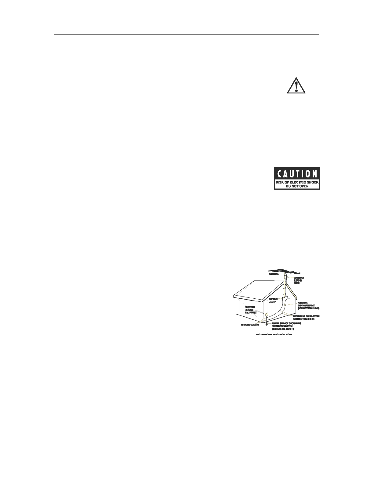
21. OUTDOOR ANTENNA INSTALLATION/SAFE ANTENNA AND CABLE CONNECTION:
• If an outside antenna or cable system is connected to the
equipment, be sure the antenna or cable system is grounded in
order to provide protection against built-up static charges and
voltage surges. Article 810 of the National Electrical Code,
ANSI/NFPA 70 (in Canada, Part 1 of the Canadian Electrical
Code) provides information regarding proper grounding of the
mast and supporting structure, grounding of the lead-in wire to
an antenna discharge unit, size of grounding conductors,
location of antenna discharge unit, connection to grounding
electrodes and requirements for the grounding electrode.
• Outside antenna system should be located well away from
power lines, electric light or power circuits and where it will
never come into contact with these power sources if it should
happen to fall. When installing an outside antenna, extreme
care should be taken to avoid touching power lines, circuits or
other power sources as this could be fatal. Because of the hazards involved, antenna installation should be
left to a professional.
4
Page 6

WELCOME
!
!
!
THANK YOU
Congratulations on becoming a Cary Audio owner!
Cary Audio would like to thank you for purchasing our products.
Since its founding in 1989, Cary Audio has stayed at the forefront of home entertainment
equipment by stubbornly adhering to the principles of quality and musicality upon which it was
founded. It’s not enough just to be able to build great sounding gear, but it needs to be wellmade, reliable, and maintain its performance and value for many years. Cary Audio has certain
criteria that have guided us since we began, and are still our primary focus.
We firmly believe in high performance products that offer incredible value for the money, backed
by superior engineering and design, and supported by exceptional customer service. Whether a
headphone amplifier or a world-class surround sound processor, Cary Audio uses the highest
quality components available within the audio circuit, resulting in extraordinary sound quality. This
is a well-known hallmark of all Cary Audio products.
For over a quarter century of providing the best in high performance music systems, Cary Audio
remains committed to our goals of building the very best products, at real-world prices, and
supporting them with world-class service. Let our passion for the very finest sound and picture
quality help you better enjoy your music and movies! Thank you for your continued support!
Cary Audio
5
Page 7

INSTALLATION
!
!
UNPACKING
!
This section describes the proper unpacking and installation procedures.
Unpacking
All Cary Audio shipping cartons have been specially designed to protect their contents and special
care has been taken to prevent damage under normal shipping conditions. Mishandling should be
evident upon inspection of the shipping container. If shipping damage is found after visual
inspection, take care not to destroy the evidence. If necessary, document the damage with
photographs and contact the transport carrier immediately.
Carefully remove your new component from its packing carton and examine it closely for signs of
shipping damage. We strongly recommend saving all original packing cartons to protect your
component from damage should you wish to store it or ship it at a later date.
Power Requirements
The SI-300.2d Digital Integrated Amplifier is designed to operate from AC main current. The AC
voltage is either 110V-120V or 220V-240V AC at 50-60 Hz.
In the Box
When unpacking your SI-300.2d, make sure the following accessories are included. You
should find the following items within the box:
• Power Cable
• Owner’s Manual
• Warranty Card
• Two Screws on Adjustable Angle Antennas
WARRANTY CARD
IN THE USA: If you are the original purchaser of a new unit purchased from an authorized Cary
Audio dealer or from CaryDirect.com, please fill out the enclosed warranty registration card and
return it to Cary Audio within 15 days of your purchase. Cary Audio also suggests that you keep
your original packing cartons in case you ever need to ship the unit. Warranty restrictions apply.
Consult the warranty section at the end of this manual for details. Please be certain to keep a copy
of the original sales receipt from your direct purchase from Cary Audio or your authorized Cary
Audio dealer to validate the warranty if ever needed. The warranty is for the original purchaser
only and does not transfer to any subsequent owner.
OUTSIDE THE USA: Your local authorized Cary Audio distributor will make its’ own warranty
policy for your country. Please check with them for the terms of warranty for your new product.
!
!
!
6
Page 8

INSTALLATION
!
!
PLACEMENT
!
In general, the location of your new SI-300.2d is not critical. However, certain precautions
must be taken to ensure optimum performance. Avoid extremely hot locations such as near
radiator or other heating units. Keep the top of the SI-300.2d clear with plenty of ventilation to
protect against overheating as the SI-300.2d can generate substantial heat.
!
!
!
!
7
Page 9

FEATURES
!
!
!
The following section describes the SI-300.2d basic features. Please read the Operation Section of this
manual to learn more on utilizing these features. The features are subject to change without notice or
obligation.
TruBit™ DSD & PCM CONVERSION AND UPSAMPLING
Upsampling can be messy, leaving behind lots of digital artifacts resulting in noise and inaccurate
signal generation. On the surface, upsampling may seem like a good idea. But if not implemented
properly it can be disastrous. Many DACs use modest DSP chips at best, or worse, the DAC chip
itself to upsample all incoming digital signals. Typically, this is done as a predefined
one-size-fits-
all
sample rate, such as 96 kHz, 384 kHz, etc. On the contrary, Cary Audio’s TruBit™ Upsampling
is a sophisticated and powerful process utilizing a dedicated 128 bit DSP engine which allows for
up to 10 different selectable TruBit™ sample rates and an increased bit depth of 32 bits for PCM
and 1 bit for DSD. This allows PCM to be converted to DSD or lower DSD rates Upsampled to
higher DSD rates. Working in tandem with our OSO™ Reclocking feature, the newly generated
signal is cross-checked multiple ways ensuring that the selected upsample rate is as if it were an
original native signal. The result is a signal free from digital artifacts that sounds accurate, pure,
and a joy to listen to
fi™
BLUETOOTH IMPLEMENTATION
!
Bluetooth modules are a fantastic and convenient way in which to share and listen to music from
online and mobile sources. It’s not unusual for companies to use such modules as a complete
end-to-end or add on solution whereby using the cheap low-grade onboard DAC chips included in
the modules and simply passing the analog signal of the module to the analog output section.
Our solution is to
fully integrate (fi™)
the digital information of the CSR aptX® lossless Bluetooth
receiver into the entire digital circuit of the SI-300.2d. This approach ensures that Bluetooth
sources have the potential to sound like any other expensive input source whereby utilizing our
sophisticated digital topology and our other integrated digital features such as; TruBit™
Upsampling, and OSO™ Reclocking,. Now your Bluetooth sources can truly be high fi.
OSO™ RECLOCKING
!
Once a digital signal is transferred into Cary Audio’s digital ecosystem via the digital inputs or CD,
it is processed with extreme care to ensure the best possible sound achievable. As a digital source
transfers from one point A to point B it creates an insidious digital problem called jitter. To deal
with this, Cary Audio uses something we call OSO™ Reclocking. While USB Asynchronous inputs
use the XMOS processor to control the clocking of the USB host, other non-USB sources don’t have
this luxury. Our solution is to re-clock all signals again once onboard, even XMOS USB, as to
ensure all jitter is virtually eliminated to a minute degree. We call this OSO™, short for “Onboard
Signal Origination” because this re-clocking and buffering creates a signal so stable and jitter free
it’s as if the origin of the signal was generated onboard and not from an external source.
XMOS xCore USB ASYNCHRONOUS
!!
XMOS is the de-facto standard in USB Audio 2.0. This design delivers bit perfect PCM audio up to
384kHz, DSD and DoP format support, round trip latencies as low as 3ms and use asynchronous
clocking for computer USB sources. This means the SI-300.2d has complete control over the audio
clock quality; essential for no-compromise digital audio systems.
8
Page 10
CONTROLS AND DISPLAYS
!
!
FRONT PANEL
!
!
!
!
!
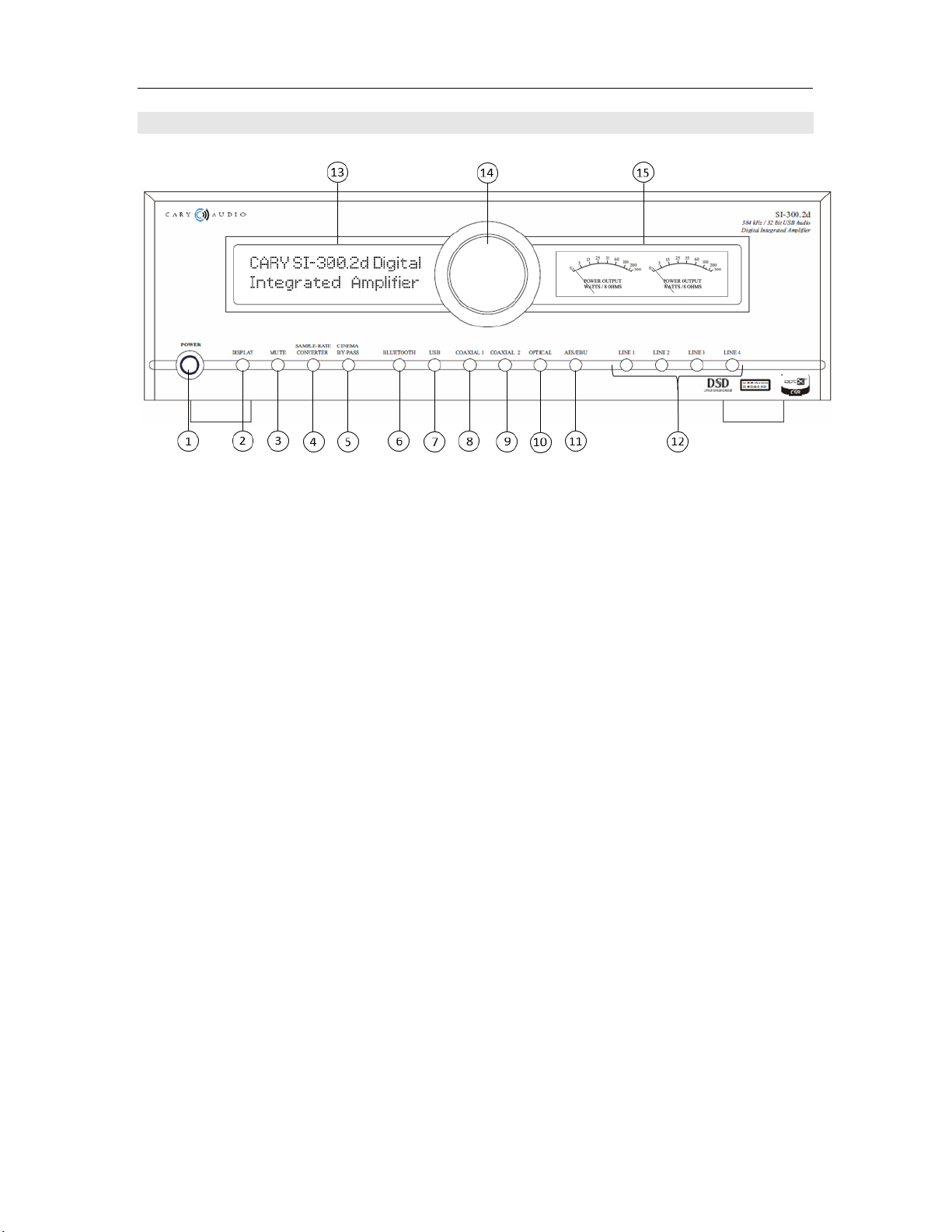
1. POWER!
Press once to turn the power ON. The blue indicator ring will blink until the unit is ready to
operate. Press again to turn the power off.
2. DISPLAY!
Press to change the brightness level of the front panel display. Low-->Medium-->High->Off
!
3. MUTE!
Press to mute the output volume. Press again to disengage mute. When disengaging, it
takes a few seconds for sound to resume.!
!
4. SAMPLE!RATE!COVERTER!BUTTON!!
Use this button to change the sample rate of the input signal via Cary Audio TruBit™
upsampling technology. Each time the button is pressed, the sample-rate will increase as
follows:
BYPASS (44.1) ---> 48 ---> 88.2 ---> 96 -à176.4 ---> 192 ---> 352.8 /384---> 705.6/768
kHz ---> DSD64 ---> DSD128 ---> DSD256
5. CINEMA!BYPASS!
Press to activate signal pass-thru (deactivating volume control) if connected to a surround
sound processor. For Line Inputs 3 & 4 only.
!
6. BLUETOOTH!INPUT!BUTTON!
Press this button to select the program source of connected/paired BLUETOOTH source.
!
7. USB!INPUT!BUTTON !
Press this button to select the PC or MAC computer connected to the digital input jack
labeled USB.
9
Page 11

CONTROLS AND DISPLAYS
!
!
8. COAXIAL!1!INPUT!BUTTON!
Press this button to select the program source connected to the digital input jack labeled
COAXIAL 1.
!
9. COAXIAL!2!INPUT!BUTTON!
Press this button to select the program source connected to the digital input jack labeled
COAXIAL 2.
10. OPTICAL!TOSLINK!INPUT!BUTTON!!
Press this button to select the program source connected to the digital input jack labeled
Optical. For digital signals over 96kHz it is usually best to use the coaxial, AES/EBU or USB
input. Many Toslink cables do not transfer signals above 96 kHz.
!
11. AES/EBU!INPUT!BUTTON!
Press this button to select the program source connected to the digital input jack labeled
AES/EBU.
12. ANALOG!LINE!LEVEL!INPUTS!1!THRU!4!!
Line 1 (RCA Single-ended), Line 2 (XLR Balanced), Line 3 (RCA Single-ended w/CINEMA
BYPASS), Line 4 (XLR Balanced w/CINEMA BYPASS).
13. ALPHANUMERIC!DISPLAY!WINDOW!
This twenty-character display provides a wide range of information concerning the operation
of the SI-300.2d.
14. VOLUME!CONTROL!
Turn knob to adjust the output volume level.
!
15. VU!METERS!
Displays the power output in wattage into an 8 ohm load.!
!
!
!
!
!
!
!
!
10
Page 12
CONTROLS AND DISPLAYS
!
!
!
REAR PANEL
!
!
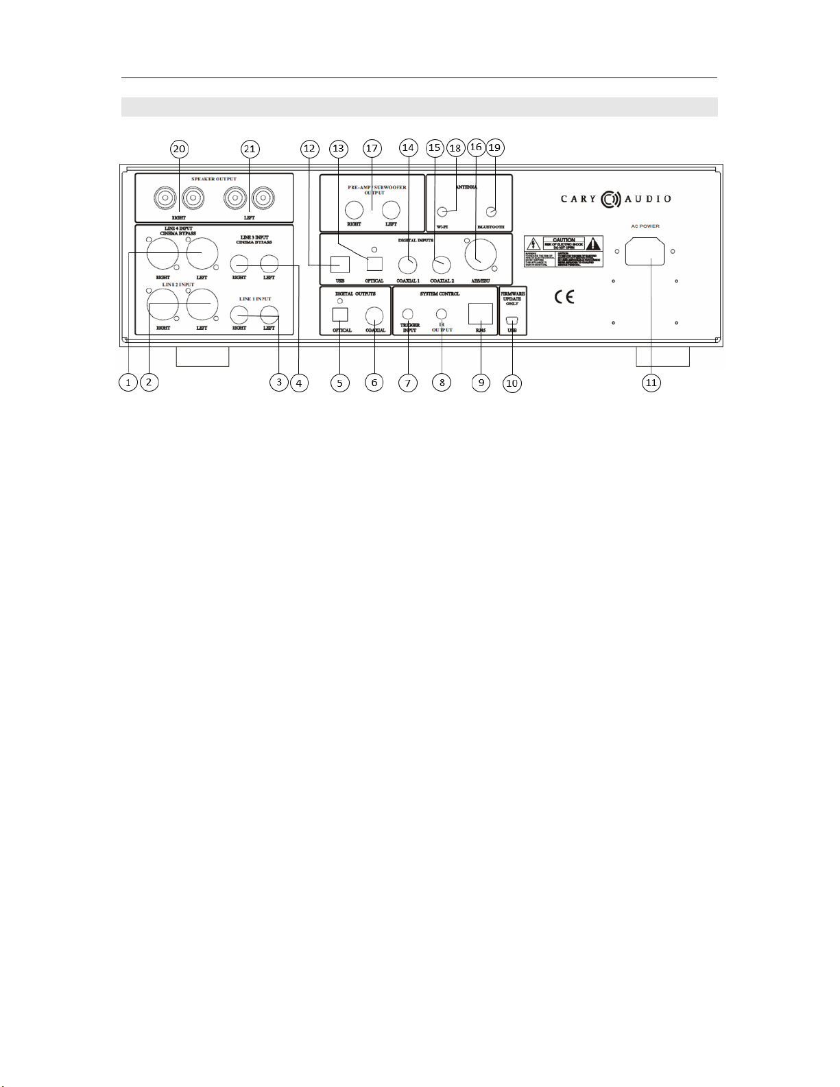
1. LINE!4!ANALOG!INPUT!JACK!(XLR!BALANCED)!W/CINEMA!BYPASS!
For connecting an XLR balanced source, or the front main Right & Left outputs of a surround
sound processor.!
!
2. LINE!2!ANALOG!INPUT!JACK!(XLR!BALANCED)!!
For connecting an XLR balanced source.
3. LINE!1!ANALOG!INPUT!JACK!(RCA!SINGLE-ENDED)!!
For connecting an RCA source.
4. LINE!3!ANALOG!INPUT!JACK!(RCA!SINGLE-ENDED)!W/CINEMA!BYPASS
For connecting an RCA source, or the front main Right & Left outputs of a surround sound
processor.
5. DIGITAL!OUTPUT!JACK!(TOSLINK)!
44.1 kHz – 192 kHz digital data output.
6. DIGITAL!OUTPUT!JACK!(COAXIAL)!!
44.1 kHz - 192 kHz digital data output.
7. DC!TRIGGER!INPUT!TERMINALS!!
Connection!of!devices!that!have!DC!+!12V!output!for!remote!turn-on/off!of!the!SI-300.2d.!
8. IR!INPUT!
Connection!of!external!IR!sensors.!
9. ETHERNET!RJ45!JACK!
For!network!system!control.!
10. MINI!USB!FIRMWARE!!
For!internal!service!use!only!
11. POWER!INPUT!(AC!IN)!
Connect!to!AC!mains!using!the!included!power!supp ly !co rd.!
11
Page 13

CONTROLS AND DISPLAYS
!
!
!
12. DIGITAL!INPUT!JACK!(USB)!
44.1!kHz!-384kHz!and!DSD!64,!128,!256!digital!data!input!to!this!jack.!
13. DIGITAL!INPUT!JACK!(OPTICAL)!
44.1!kHz!-192kHz!digital!data!input!to!this!jack.!
14. DIGITAL!INPUT!JACK!(COAXIAL!1)!
44.1!kHz!-192kHz!digital!data!input!to!this!jack.!
15. DIGITAL!INPUT!JACK!(COAXIAL!2)!
44.1!kHz!-192kHz!digital!data!input!to!this!jack.!
16. DIGITAL!INPUT!JACK!(AES/EBU)!
44.1 kHz -192kHz digital data input to this jack.
17. PREAMPLIFER/SUBWOOFER!OUTPUTS!
For connection to an external amplifier or a subwoofer with built-in amplifier. These outputs
are variable (NOT fixed).
18. Wi-Fi!ANTENNA!
Wireless!network!connection!for!system!control.!
19. BLUETOOTH!ANTENNA!
44.1 kHz CSR aptX® lossless wireless digital audio receive port.
20. SPEAKER!CONNECTOR!(RIGHT!CHANNEL)!
Connect your right channel speaker’s positive (Red +) and negative (Black -) to the
corresponding (red +) and (Black -) connectors on the SI-300.2d. It is recommended to use
a quality Spade or Banana connector. NOTE: Make sure the system power is off before
making any connections.
!
21. SPEAKER!CONNECTOR!(LEFT!CHANNEL)!
Connect your left channel speaker’s positive (Red +) and negative (Black -) to the
corresponding (red +) and (Black -) connectors on the SI-300.2d. It is recommended to use
a quality Spade or Banana connector. NOTE: Make sure the system power is off before
making any connections.
!
!
!
!
!
12
Page 14
CONTROLS AND DISPLAYS
!
!
REMOTE CONTROL
!
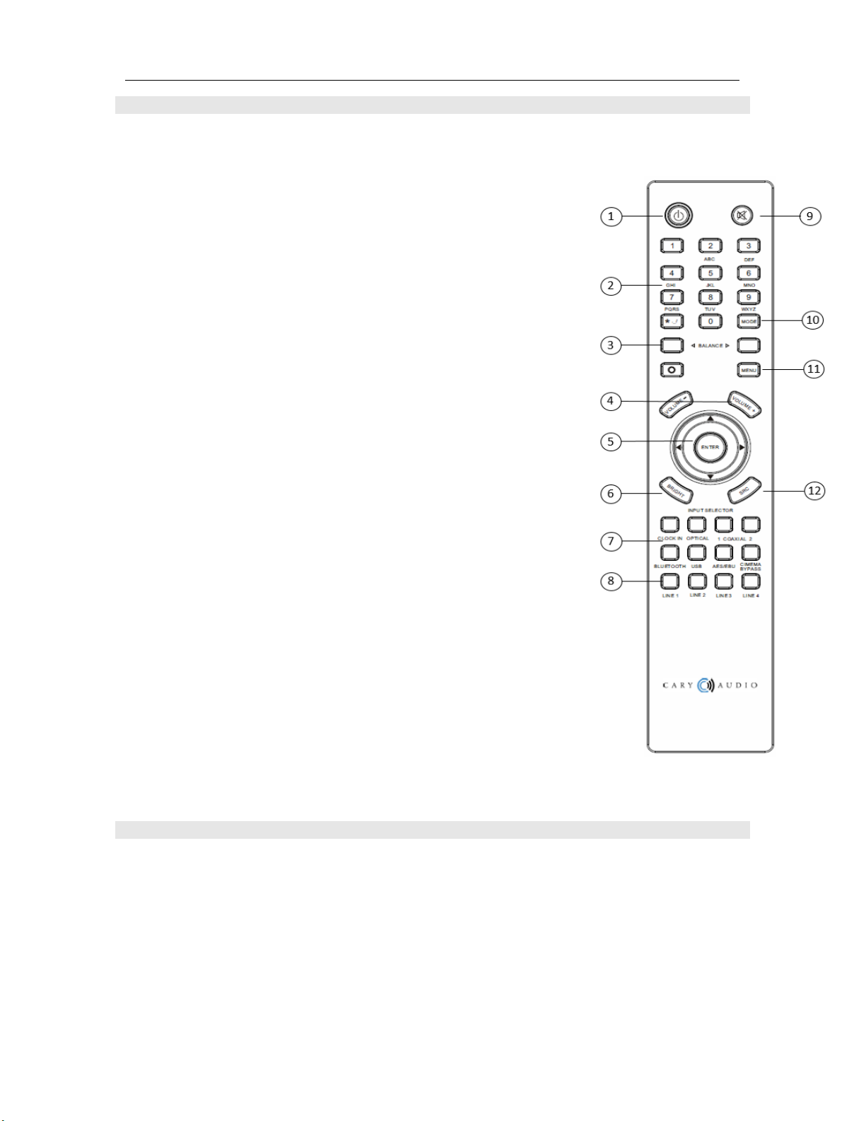
This section explains how to use the remote control to set up and operate the SI-300.2d.
1. POWER: Use to turn the power on and off.!
2. INPUT KEYS: Use for Wi-Fi security code input.!
3. BALANCE: Use to adjust the speaker balance right or left.
4. VOLUME -/+: Decrease or increase volume for the analog outputs.
5. NAVIGATION CONTROL: Use to navigate the menu structure
6. BRIGHT: Use to select the player to display various brightness levels
or turn the display off.
7. DIGITAL INPUT SOURCE SELECTOR: Use to select the desired
digital input source.
8. ANALOG INPUT SOURCE SELECTOR: Use to select the desired
analog input source.
9. MUTE: Use to mute sound. Press again to resume sound.!
10. MODE: Use this button to increase the output by +6db for use when
using low output sources. When engaged a “D” will appear next to
the volume.
11. MENU: Use to display the menu system of the SI-300.2d.!
12. SRC: Sample Rate Converter. Press to select a TruBit™ upsamplerate.
APP CONTROL FOR iOS AND ANDROID (FUTURE)
!
The SI-300.2d has a custom App for iOS and Android devices that can be downloaded free of charge
from Apple iTunes or the Google/Android Apps Marketplace. Utilizing the SI-300.2d Ethernet port or
built-in Wi-Fi connection, these Apps can control all functions of the SI-300.2d once the SI-300.2d
has established a network connection. For information on connecting to a network, please be sure
to read the Ethernet and Wi-Fi Setup section of the manual.
13
Page 15

MENU OPERATION
!
!
!
SETUP MENU OVERVIEW
1. Press “MENU” on the hand held remote.
2. The display screen will show the Menu Mode as follows:
SETUP MENU
Volume Setup
IR Controls
Ethernet
Wi-Fi
EXIT
3. Using the “UP” or “DOWN” arrow keys on the remote,
highlight
your selection and
press
Enter.
4. Make your selections for each mode and
press
Enter to back out to the Setup Menu.
5. When finished,
select
EXIT and
press
Enter to leave the Setup Menu.
PROCEDURES FOR NAVIGATING ETHERNET AND WI-FI SUB MENUS
Select Ethernet or Wi-Fi and press enter.
1. A * will denote the active sub menu topic with a selection choice below it.
Enable *
No!
2. To change the default selection of a sub menu topic, press enter. Notice the * will move
down to indicate the active selection which will blink.
STEP!1!
Enable:
No (blink) *
3. As it blinks, use the up/down keys on the remote to change the available choices and press
enter to make your selection. Note that all selection choices are not visible and you must
use the up/down keys to scroll all available choices.
STEP!2!!
Enable:
Yes (blink) *
14
Page 16

MENU OPERATION
!
!
!
4. Once a selection for the sub menu topic is made, the * will move back up to the sub menu
topic like so, showing your selection beneath it.
Enable: *
Yes !
5. Use the up/down keys on the remote to go to the next sub menu topic and repeat above
steps for all Ethernet and Wi-Fi sub menu topics.
IP Assign: *
DHCP
6. For alphanumeric entries, use the keypad. Although the letters do not appear on the
remote, they function like a telephone keypad as follows; Key 2 (2abcABC), key 3
(3defDEF), key 4 (4ghiGHI), key 5 (5jklJKL), key 6 (6mnoMNO), key 7 (7pqrsPQRS), key 8
(8tuvTUV), key 9 (9wxyzWXYZ).
SETUP MENU – EXPANDED VIEW AND FUNCTIONS
Volume Setup
1. Master Volume or Independent Volume
o If you wish to volume match different sources set to Independent, otherwise set
to Master.
IR Controls
1. Front
o Select Front if there is only a need to control the SI-300.2d via the hand held
remote and have line of sight to the front panel of the unit.
2. Rear
o Select Rear if there are IR sensors connected to the rear of the SI-300.2d for when
the unit is installed inside a rack or out of line of sight of the remote.
3. Both
o Select Both if both Front and Rear conditions apply and to be able to have flexibility
of controlling either way or simultaneously.
15
Page 17

MENU OPERATION
!
!
!
NETWORK ETHERNET AND WI-FI SETUP (FROM DAC)
The SI-300.2d comes with both an Ethernet Port and built-in Wi-Fi for connection to your network
for controlling the SI-300.2d via network control systems as well as iOS and Android Apps.
Ethernet
1. Enable;
Yes or No
Yes is the default setting.
2. IP Assign:
DHCP or Static
Select DHCP for an IP address to be assigned automatically to the SI-300.2d (most
common method).
(If Static is selected, follow steps a & b)
a) Assign IP:
--- --- --- ---
Enter your desired IP address using the hand held remote control.
b) Connect:
Yes
After entering your desired IP address,
select
YES.
3. Status:
Connected
Connected will display once successfully connected to your network. If the connection
was unsuccessful No Connection will be displayed. If this happens, make sure your
Ethernet cable is plugged into the SI-300.2d and your router/network is setup for DHCP.
After confirming, make sure the above selections are correct and jump to Reset
Connection below.
4. Reset Connection:
Yes or No
If your connection was unsuccessful, or you just need to reset the network connection for
any reason, select YES.
16
Page 18

MENU OPERATION
!
!
!
5. Local Port:
Displays the assigned local port.
6. IP Address:
Displays the assigned IP address.
7. Net Mask Addr:
Displays the assigned net mask address.
8. Gateway Addr:
Displays the assigned gateway address.
9. MAC Addr:
Displays the assigned MAC address.
10. Return
Select return to the Ethernet Setup menu.
Wi-Fi
1. Enable;
Yes or No
No is the default setting for Wi-Fi.
Select
YES.
2. IP Assign:
DHCP or Static
Select DHCP for an IP address to be assigned automatically to the SI-300.2d (most
common method).
(If Static is selected, follow steps a thru d. Otherwise skip to number 3)
a) Scan Wi-Fi Networks:
Yes
Select
Yes to display available Wi-Fi networks. Choose the network you wish to
connect to and
select it by pressing
Enter on the hand held remote.
17
Page 19

MENU OPERATION
!
!
!
b) Enter Wi-Fi Key:
--------------------
If the chosen network is secured, enter the security key code of your Wi-Fi network
using the hand held remote.
Use the number keys on the hand held remote as follows for all alphanumeric characters.
Note: For spaces, press the “0” key for a blank space. For special characters, press the *._/ key.
c) Assign IP: --- --- --- ---
Enter your desired IP address using the hand held remote control.
d) Connect:
Yes
After successfully entering the network security key,
select
YES to connect.
3. Scan Wi-Fi Networks:
Yes
Select
Yes to display available Wi-Fi networks. Choose the network you wish to connect
to and
select it by pressing
Enter on the hand held remote.
4. Enter Wi-Fi Key: --------------------
If the chosen network is secured, enter the security key code of your Wi-Fi network using
the hand held remote.
5. Connect:
Yes
After successfully entering the network security key,
select
YES to connect.
6. Status:
Connected
Connected will display once successfully connected to your network. If the connection
was unsuccessful No Connection will be displayed. If this happens, make sure your WiFi is enabled on the SI-300.2d and your router/network is setup for DHCP. After
confirming, make sure the above selections are correct and jump to Reset Connection
below.
18
Page 20

MENU OPERATION
!
!
!
7. Reset Connection:
Yes or No
If your connection was unsuccessful, or you just need to reset the network connection for
any reason, select YES.
8. Local Port:
Displays the assigned local port.
9. IP Address:
Displays the assigned IP address.
10. Net Mask Addr:
Displays the assigned net mask address.
11. Gateway Addr:
Displays the assigned gateway address.
12. MAC Addr:
Displays the assigned MAC address.
13. Return
Select return to the Ethernet Setup menu.
Exit
4.
Highlight
EXIT and
press
ENTER on the hand held remote to
leave the
SETUP MENU and
return to normal operation.
19
Page 21

MENU OPERATION
!
!
!
NETWORK WI-FI SETUP (FROM APP)
Once you have downloaded the SI-300.2d control app for your iOS or Android device, please follow
the step below.
By default, Ethernet is enabled for the SI-300.2d. Simply plug an Ethernet cable into the Ethernet
port on the SI-300.2d. If you have trouble connecting the app, be sure to confirm the SI-300.2d’s
Ethernet is connected using the previous instructions under “NETWORK ETHERNET AND WI-FI
SETUP”. Make sure the Ethernet cable is firmly connected and the SI-300.2d shows “Connected”
under Ethernet settings. If not, try resetting the Ethernet and repeat steps.
Wi-Fi Setup
To Setup Wi-Fi from the app you MUST first connect the SI-300.2d to Ethernet and establish a
connection from the steps above.
(This step assumes you have NOT setup the Wi-Fi from the SI-300.2d itself).
1.
Open
the app and it will automatically search for Ethernet connected SI-300.2d’s.
2. C
lick
on the Settings icon
in the app
then
select
Network.
3.
Select
Wi-Fi/Wireless.
4. From the Wi-Fi AP
dropdown box, select
your wireless network.
5. Enter your Security Key and
select
Save.
6. Next,
click
the red Reset Network button.
7. Confirm the Wi-Fi is connected in the SI-300.2d’s Setup Menu.
1. You should now be able to unplug your Ethernet connection from the SI-300.2d with all
connectivity now being Wi-Fi.
20
Page 22

MAINTENANCE FUNCTIONS
!
!
!
MAINTENANCE FUNCTIONS
Checking the Software Versions, Date and Serial Number of the SI-300.2d.
From hand held remote
Ø
Enter
“8,5,2,1” quickly
on the hand held remote
. This will show the software version, date
and serial number of the unit for a few seconds, then default to normal operation.
From App
Ø C
lick
on the Settings icon
in the app
then
select
About.
Resetting the SI-300.2d.
From hand held remote
Ø
Enter
“8,5,2,5” quickly
on the hand held remote
. This will reset the unit.
From App
Ø C
lick
on the Settings icon
in the app
then
select
Reset.
Note: If the corresponding information fails to engage or display when using the hand held remote,
re-enter the sequence faster and closer to the unit.
21
Page 23

GENERAL OPERATION
!
!
!
POWER ON/OFF
!
Press the power button on the front panel or via the IR remote. The blue ring around the power
button will blink for several seconds while the SI-300.2d warms up and initializes. Once the blue
ring steadily glows and you hear a click, the SI-300.2d is ready for use. When powering off, it is
recommended to first turn the volume down to a low level, then press the power button once
again. The SI-300.2d will power on to the same input and volume setting last used. This is why
it is recommended to turn the volume down prior to powering off as to not damage the unit,
speakers, or your hearing.
SPEAKER CONNECTIONS
!
The SI-300.d is equipped with high quality 5-way speaker binding posts. Simply connect your
speakers positive + and negative – connections to the corresponding positive + and negative –
connectors on the rear of the SI-300.2d. Do not make speaker connections when the unit is
powered on and always start at the speaker end first. We recommend a high quality speaker
cable with high quality spade or banana connectors.
SOURCE CONNECTIONS
!
Connect all sources to the SI-300.2d with quality RCA or XLR cables for analog sources and
quality USB, coaxial, optical, and AES/EBU cables for digital sources. It is not recommended to
connect or disconnect any source(s) to the SI-300.d while powered on. If your source(s) have a
variable output volume it is typically best to adjust them to 100% output. For sources that have
a very high output (above 2.0 volts) you may want to use the “Mode” button on the IR remote
so that the letter “D” is NOT display next to the volume range on the SI-300.2d front panel. For
sources of less than or equal to 2.0v you may want to experiment with the IR remote “Mode”
function to display the letter “D” next to the volume range.
SWITCHING INPUTS
!
To switch inputs, simply press the desired input on the SI-300.2d front panel, on the IR remote
control, or via the Android or iOS control apps available for free. When switching inputs, the SI-
300.2d will soft mute the output circuit for a few seconds as a precautionary measure. It is also
recommended to turn the volume down to a reasonable level when switching inputs.
MUTING THE SOUND
!
You may completely mute the sound of the SI-300.2d either via the front panel display or the IR
remote control. When mute is engaged the word “Mute” will display on the front panel in place
of the volume range. Press the Mute button again or adjust the volume up to disengage mute.
Once disengaged it will take a few seconds for the sound to resume.
VU METERS
!
A handsome and fun feature of the SI-300.2d are the VU Meters. They show the power output
in wattage into a nominal 8 ohm load. The needles will move in accordance to the amount of
power output. The higher the output the more the needles will move.
Caution: The SI-300.2d is a very powerful amplifier. Please be mindful of this as to not
damage your speakers or your hearing for the sake of watching the meters dance!
22
Page 24
DIGITAL INPUT OPERATION
!
!
!
USING THE ANALOG INPUTS
!
The Analog inputs include both RCA single-end and XLR balanced connections; LINE 1, LINE 2,
LINE 3, LINE 4.
Ø LINE 1 = RCA connection
Ø LINE 2 = XLR connection
Ø LINE 3 = RCA connection with Cinema Bypass function.
Ø LINE 4 = XLR connection with Cinema Bypass function.
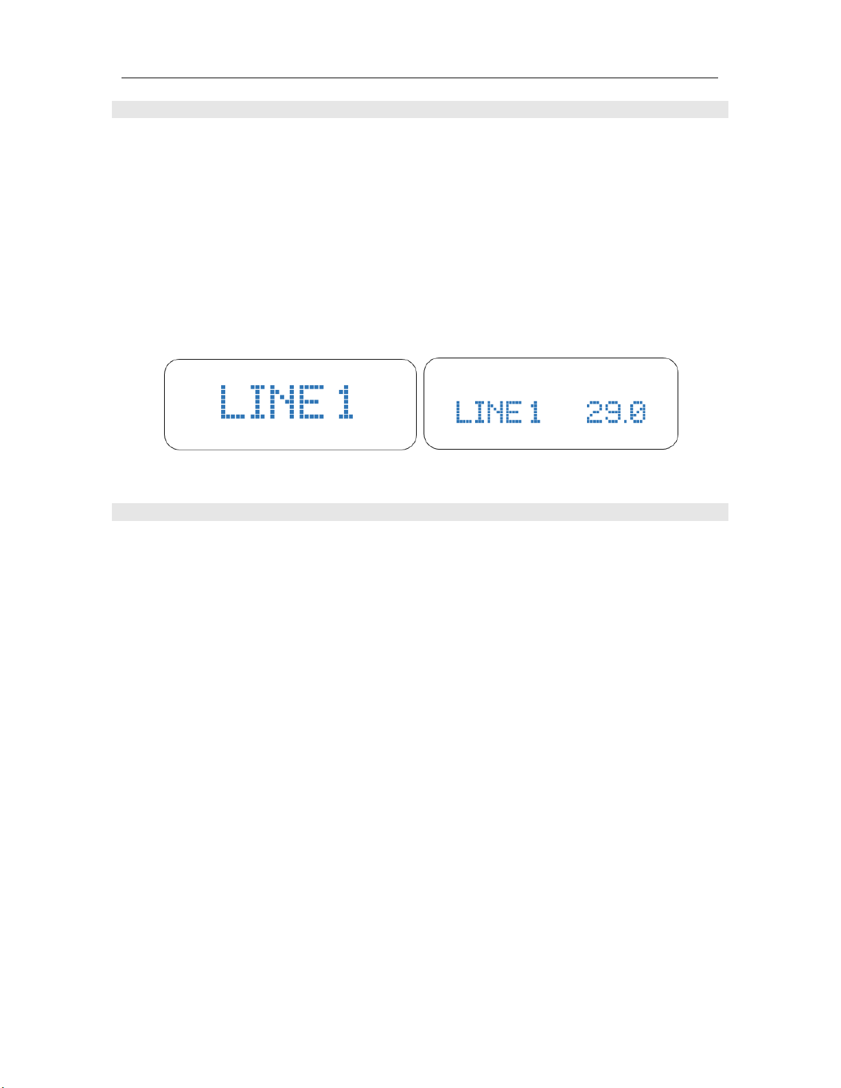
1. Select the desired input by pressing LINE 1, LINE 2, LINE 3, or LINE 4 button. Once
selected, the SI-300.2d will confirm your selection by display the input name in LARGE print for
a few seconds, and then will default to the following display.
CINEMA BYPASS FUNCTION
!
The Cinema Bypass function is used when combining both a traditional 2 channel stereo system
and a multi-channel surround sound system into one system. To do this, simply connect the
surround sound processor main front Left & Right channels outputs to either LINE 3 or LINE 4
on the SI-300.2d. (The remaining outputs of the surround sound processor will connect directly
to the corresponding multi-channel amplifier(s) inputs). When Cinema Bypass in engaged on
the SI-300.2d the LINE 3 or LINE 4 input will pass directly to the SI-300.2d amplifier stage
bypassing the SI-300.2d’s volume control. Therefore, once engaged the surround sound
processor will control all volume for all channels even though the SI-300.2d is acting as the
amplifier for the main front Left & Right stereo channels.
1.
Connect
the surround sound processor main front Left & Right channels outputs to
either LINE 3 or LINE 4. If the surround sound processor uses RCA outputs use LINE 3. If
the surround sound processor uses XLR outputs use LINE 4.
2.
Select
Input LINE 3 or LINE 4.
3. Once your input is selected,
Press
CINEMA BYPASS on the front panel or via the IR
remote.
NOTE: A caution message will appear on the SI-300.2d display panel prompting you to be
sure the volume is turned down on your surround sound processor as once engaged the
volume will be controlled by the surround sound processor.
4.
After checking the surround sound processor volume, Press
the CINEMA BYPASS button
again on the front panel or
Enter
on the IR remote to engage.
5. To
deselect
CIMEMA BYPASS mode,
simply select another input on the SI-300.d.
23
Page 25
DIGITAL INPUT OPERATION
!
!
!
USING THE SPDIF INPUTS
!
The SPDIF inputs include; COAXIAL 1, COAXIAL 2, OPTICAL, and AES/EBU.
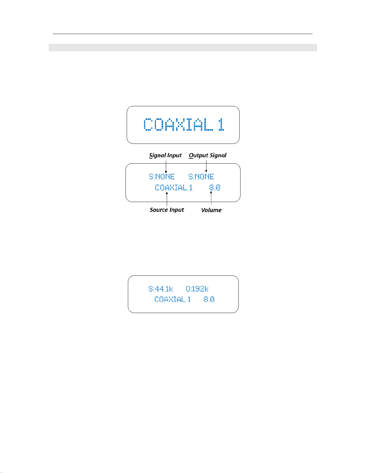
1. Select the desired input by pressing COAXIAL 1, COAXIAL 2, AES/EBU or OPTICAL
button. Once selected, the SI-300.2d will confirm your selection by display the input name in
LARGE print for a few seconds, and then will default to the following display.
!
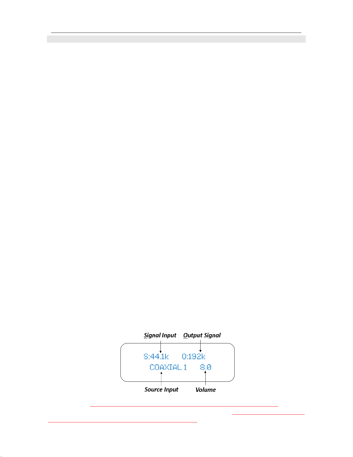
2. Initiate playback of the corresponding SPDIF source. Once playback begins the Signal Input will
appear in the display window. The Output Signal will display based on its setting. For example,
if the Signal Input is 44.1K and the TruBit™ Sample Rate Converter is set to 192K the display
will appear as follows: (
Please read the TruBit™ Sample Rate Converter section of this manual
for more on its operation
).
NOTES:
• Digital input signals can be outputted in both digital format (via the COAXIAL and
TOSLINK DIGITAL OUTPUTS) and analog format (RCA and Balanced XLR)
simultaneously.
• Only linear PCM signals with a sampling frequency of 44.1kHz, 48kHz, 88.2kHz, 96kHz,
176.4kHz or 192kHz can be played over the SPDIF inputs. Do not input any digital
signal other than linear pulse code modulation (PCM) signals (CD-ROM, Dolby Digital,
DTS signals, etc.). Doing so will generate output noise that could damage the speakers.
24
Page 26

USB OPERATION
!
!
!
USB REQUIREMENTS
!
The following are minimum required specifications for using with the SI-300.2d USB port. If your
computer does not meet these requirements, you will experience lagging of audio and possible
freezing of your computer when attempting to operate the SI-300.2d.
WINDOWS
• Microsoft Windows XP (32bit), Microsoft Windows Vista (32 or 64 bit), Microsoft Windows
7 (32 or 64 bit), Microsoft Windows 8 (32 or 64 bit), Microsoft Windows 8.1 (32 or 64 bit),
Microsoft Windows 10 (32 or 64 bit)
• Available USB 2.0 Port (High speed for USB2.0)
• ASIO/KS/WASAPI/Direct sound drivers for Windows XP to 10
MACINTOSH
• NO driver is needed for MAC OS version 10.6.4 and above.
!
PC DRIVER INSTALLATON
!
To use the SI-300.2d USB port on a Windows based PC, you MUST install the provided driver which
is downloadable from The SI-300.2d product page on the Cary Audio website. We advise that users
read all instructions carefully before installing and following all instructions during the installation
process.
Installing the PC Driver:
(1) Download the CARY XMOS USBAUDIO V3.34.0 (or later) USB Driver from the Cary Audio SI-
300.2d product page.
(2) Unzip/extract the Driver folder and save to you desktop.
(3) Connect a USB cable from the computer to the USB input of the SI-300.2d.
(4) Power on the SI-300.2d. Wait until power button blue ring stops flashing, then select the USB
input.
(5) Open the driver folder you saved to your desktop and double click the Setup.exe.
(6) Follow the on-screen installation instructions.
(7) Click “Finish” when complete.
!
MACINTOSH USB AUDIO SETUP
!
Start the setting on System Preferences Panel on MACINTOSH:
(1) Power on the SI-300.2d and connect your USB cable from the unit to your MAC.
(2) Open the System Preferences panel on your MAC.
(3) Select ”SOUND” icon.
(4) Select “OUTPUT.”
(5) Select “xCore USB Audio 2.0” Output”.
(6) Close the System Preferences Panel.
25
Page 27

USB OPERATION
!
!
!
USB AUDIO PLAYBACK
To playback music via the USB input and a connected computer, it is necessary to use a “media
player” such as JRiver, Foobar, etc. The USB input is capable of extremely high resolution audio, up
to 32 bit/ 384kHz PCM, or DSD up to 256. (iTunes nor Windows Media Player is capable of such
resolutions on their own). However, please know your media player software thoroughly to know
what its limitations may or may not be as it relates to setup, PCM resolutions, DSD capability and
supported file types.
Make sure drivers (PC) have been installed by following the instructions above, under
USB
Requirements
and
Installation
, then do as follows:
(1) If not already on, make sure the SI-300.2d is turned ON and connected to your computer
via a high quality USB cable, and then turn ON your PC or MAC.
a. MAC - Make sure “xCore USB Audio 2.0 Output” is selected in the MAC Sound
Preferences in the System Preferences Panel.
b. Windows PC - Make sure “XMOS XS1-U8 MFA is selected as the Playback
device under the Sound preferences in the Windows Control Panel.
(2) Select the USB input by pressing the USB input button on the front panel of the SI-300.2d
or pressing the USB button on the hand held remote. “USB” will appear on the display
screen.
(3) Open your media player software audio settings and make sure “TUSBAudioASIO Driver
(ASIO) is selected as the Audio or Output Device. If there is a separate Audio Output
Mode setting for you media player, select ASIO.
(4) Playback music through the media player software.
NOTE: Some media players have Smartphone and tablet Apps that allow you to control the PC or
MAC software via the Smartphone or tablet. Otherwise, all control must be done via the computer.
USB DSD PLAYBACK
!
This requires the media player to support native DSD or “DSD over PCM” (DoP). It is recommended
to use native DSD for PC (capable up to DSD256) and DoP for MAC (capable up to DoP128).
Therefore, it is necessary to check your media player settings to send either DSD or DoP depending
on your computer and media player. Upon playback, the display screen of the SI-300.2d will show
either DoP64, DoP128 (PC or MAC), or DSD64, DSD128, or DSD256 (PC Only).
For now, DSD playback on MAC is limited to DoP64 and DoP128. You may also need to set the MIDI
Audio of the MAC computer to 24 Bit.
(1) In Applications,
open
the Utilities folder.
(2)
Open
Audio MIDI Setup.
(3)
Select
the XCore Audio Output on the left panel.
(4) Next to Format,
select
the highest supported sample rate in the first dropdown box, and
Select 2ch-24bit Integer in the second dropdown box
NOTE: TruBit™ Upsampling Sample Rate Converter does NOT engage for the USB source. Since
USB playback is dependent on media player software of the PC or MAC, you must select any desired
upsampling within the chosen media player software itself.
26
Page 28

BLUETOOTH OPERATION
!
!
!
CSR aptX® lossless Bluetooth audio is capable of CD quality audio when using an aptX® source
device. For more information, please visit CSR’s web site at http://www.csr.com/products/61/aptx-
lossless.
BLUETOOTH CONNECTION
!
Pairing a device with the SI-300.2d
When connecting a Bluetooth device to the unit for the first time, the device is required to be
registered to the unit. This process is called “PAIRING.” Once pairing is completed, subsequent
connection can be made with a couple of easy steps.
Initial Pairing Steps
(1) Select the BLUETOOTH input on the SI-300.2D and the display will show “Enter Pairing”.
(2) Go to the “
Settings
” of your device and find
Bluetooth settings
and make sure Bluetooth
function is ON and search for Bluetooth sources.
(3) “CARY SI-300.2d” should appear on your device. Once it does, select it. After pairing is
complete, the display of SI-300.2d will show “Pairing Successfully”.
NOTE: If pairing information is deleted from your device, you will need to perform pairing of that
device again in order to connect.
BLUETOOTH PLAYBACK
!
Once pairing has successfully been completed, you can easily enjoy music from your portable
devices as follows.
(1) Select the BLUETOOTH input on the SI-300.2d front panel or on the hand held
remote.
(2) Double check your device Bluetooth setting and make sure “CARY SI-300.2d” is
selected.
(3) Begin playback of music on your device, which can include stored music files or music
apps, such as Pandora®, Spotify®, iHeart Radio®, etc.
(4) If you see a “play to” icon; in your music app, tap it and select “CARY SI-300.2d”
to ensure the signal is playing to the SI-300.2d.
To get the most of our
fi™Bluetooth Implementation
during playback you can utilize our TruBit™
PCM & DSD conversion and upsampling for a superior listening experience of Bluetooth sources.
27
Page 29
TruBit™ UPSAMPLING OPERATION
!
!
!
PCM TO DSD CONVERSION AND UPSAMPLE RATE CONVERTER FUNCTION
!
TruBit™ PCM & DSD Upsampling is a powerful upsampling technology used to upsample lower
sample rates to higher sample rate and increases the bit depth to 32 bits in the digital domain via a
dedicated 128 bit DSP engine prior to analog conversion. This can be very useful in achieving a
more enjoyable listening experience. Once a native input signal is changed to a selected higher
sample rate, the bit depth will also automatically increase to 32 bits for PCM signals and 1 bit for
DSD signals. This also allow for conversion of PCM signals to DSD, or lower DSD rates to higher
DSD rates. However, like all-powerful tools, this too should be used prudently. We do not take a
blanket “higher is better” approach to upsampling. It is important to experiment with different rates
depending on your source or source material. Many times a native rate might be preferred whereas
some recordings or files formats might benefit from a higher sampling rate, and so on.
The available selectable sample rates depend on the input signals original sample rate. For
example, above 192 kHz the available rate(s) will only be in multiples of either 44.1 kHz or 48 kHz
as follows:
Input signal rates of 44.1 or multiples of:
BYPASS (44.1) ---> 48 ---> 88.2 ---> 96--> 176.4 ---> 192 ---> 352.8---> 705.6
---> DSD64 ---> DSD128 ---> DSD256
Input signal rates of 48 or multiples of:
BYPASS (44.1) ---> 48 ---> 88.2 ---> 96--> 176.4 ---> 192 ---> 384--->768
---> DSD64 ---> DSD128 ---> DSD256.
Pressing the “
Sample Rate Converter” button
on the front panel, or the “
SRC
” button on the
hand held remote will cycle through the available sample rates.
• The BYPASS mode will pass the input signal rate out in its native rate without any
upsampling.
• When an upsample rate is selected, the SI-300.2d will upsample all incoming rates
lower than the selected sample rate up to the selected sample rate as well as increase the
bit depth to 32 bits. Any signals played that are equal to or higher than the selected sample
rate will playback unchanged. Each of the SI-300.2d inputs will remember the sample rate
as set for that input.
NOTE: TruBit™ Upsampling Sample Rate Converter does NOT engage for the USB source. Since
USB playback is dependent on media player software of the PC or MAC, you must select any desired
upsampling within the chosen media player software itself.
28
Page 30

SPECIFICATIONS
!
!
!
The following section describes the SI-300.2d basic specifications. The specifications are subject
to change without notice or obligation.
AMPLIFIER SPECIFICATIONS
................................................................................................................................................
Power Output 2 x 300 watt RMS into 8 W from 20 Hz - 20 kHz
2 x 450 watt RMS into 4 W from 20 Hz - 20 kHz
................................................................................................................................................
Circuit Type Solid State, Class A/B
................................................................................................................................................
Frequency Response
(@ 10dB below rated
output power) 10Hz – 50 KHz +/- 0.1dB
................................................................................................................................................
Distortion (SMPTE-1M) <0.5%
................................................................................................................................................
S/N Ratio >100dB, “A” weighted
................................................................................................................................................
Protection Full short circuit, thermal, ultrasonic,
RF signal muting & current limiter
................................................................................................................................................
ANALOG INPUTS
................................................................................................................................................
RCA Single Ended 2 Pair (10k W Input Impedance), 1 pr. Cinema Bypass
XLR (Balanced) 2 Pair (20k W Input Impedance), 1 pr. Cinema Bypass
................................................................................................................................................
DIGITAL INPUTS
................................................................................................................................................
USB (Type-B) XMOS Asynchronous
Sample Frequency (Fs) from 44.1 kHz to 384 kHz,
16 bit to 32 bit, DSD 64, DSD 128 and DSD 256(PC Only).
................................................................................................................................................
Coaxial (2) Sample Frequency
Optical (1) (Fs) from 44.1 kHz to 192 kHz, 16 bit to 24 bit
AES/EBU (1)
................................................................................................................................................
Bluetooth (1) Sample Frequency (Fs) 44.1 kHz, 16 bit.
CSR Bluetooth v 4.0 with aptX® low latency audio
decoder.
DIGITAL OUTPUTS
................................................................................................................................................
Coaxial (1) Sample Frequency
Optical (1) (Fs) from 44.1 kHz to 192 kHz, 16 bit to 24 bit
29
Page 31

SPECIFICATIONS
!
!
!
DIGITAL SPECIFICATIONS
................................................................................................................................................
Master Clock Jitter Below measurable levels
................................................................................................................................................
Digital Filter 8x Oversampling Digital Filter
................................................................................................................................................
Digital/Analog Converters 2 channel AK4490EQ
................................................................................................................................................
Analog Filter 3rd Order Bessel
................................................................................................................................................
GENERAL SPECIFICATIONS
................................................................................................................................................
Control Trigger input 12VDC x1
IR control x1
................................................................................................................................................
Communication Ethernet RJ45 full remote configuration interface
Wi-Fi 802.11 b/g/n
................................................................................................................................................
Power Input Configured at factory for either 110-120 or 220-240 VAC,
50-60 Hz
................................................................................................................................................
Power Consumption 950 Watts
................................................................................................................................................
Dimensions 6.0″ H x 17.25″ W x 18.0” D
................................................................................................................................................
Weight 52 lbs.
!
USB PLAYBACK (PCM & DSD)
................................................................................................................................................
Frequency Range 2 Hz - 100 kHz
................................................................................................................................................
Signal System 16, 20, 24, & 32 bit PCM and 1 bit DSD
................................................................................................................................................
Sampling Frequency 44.1 kHz to 384 kHz PCM and 2.822MHz – 11.288 MHz DSD
................................................................................................................................................
Dynamic Range 123 dB
................................................................................................................................................
DSD System Clock Frequency 22.5792 MHz
................................................................................................................................................
Signal-to-Noise Ratio 112 dB
................................................................................................................................................
30
Page 32

SPECIFICATIONS
!
!
!
SPDIF PLAYBACK (PCM) COAXIAL, TOSLINK, AES/EBU
................................................................................................................................................
Frequency Range 2 Hz - 100 kHz
................................................................................................................................................
Signal System 16, 20, and 24 bit
................................................................................................................................................
Sampling Frequency 44.1 kHz to 192 kHz PCM
................................................................................................................................................
Dynamic Range 123 dB
................................................................................................................................................
System Clock Frequency 22.5792 MHz
................................................................................................................................................
Signal-to-Noise Ratio 112 dB
................................................................................................................................................
31
Page 33
SERVICE AND CARE
!
!
!
CARE AND CLEANING
!
The cabinet housing and front panel of the SI-300.2d may be cleaned with a soft cloth and
Windex or a window cleaner. The frequency of cleaning will be governed by how many hours
the SI-300.2d is operated and by operating environment cleanliness.
CAUTION:
• Do not let any liquids spill into the vents on top of the unit.
AC POWER FUSE REPLACEMENT
The!fuse!is!located!inside!the!chassis!and!is!not!user!serviceable.!If!the!unit!does!not!power!up,!
contact!an!authorized!service!representative. Never replace the fuse with any other value than
a two (2) amp slow blow fuse, 250V for a unit configured to operate at 110V-120V AC. Never
use any other value than a one (1) amp slow blow fuse, 250V for a unit configured to operate at
220V-240V AC. The AC Power Cord must be unplugged from the AC Power jack on the back of
the unit prior to replacing the fuse. Set the unit Power On/Off switch to the Off position and plug
the AC Power cord back into the AC Power jack. Then set the Power On/Off switch to the On
position and verify proper operation. Contact Cary Audio for advice if the fuse repeatedly blows.!
!
FACTORY SERVICE
!
Careful consideration has been given to the design of your SI-300.2d to keep maintenance
problems to a minimum. Any problems or requests for service should be referred to our
Customer Service Department at 919-355-0010. DO NOT return the SI-300.2d to the factory
without a Return Merchandise Authorization (RMA) number from our online Customer Service
Center (www.caryaudio.com).
Cary Audio will assume no responsibility if the shipping company refuses to pay for damage due
to your improper packing or lack of insurance should the unit be lost or damaged in shipment.
Please retain and always use the original shipping carton for shipping the player. Also, Cary
Audio reserves the right to return products sent in for service in a new box set at the customer’s
expense if the original packing material was damaged in the initial shipment, or if it is deemed
unsatisfactory to use in return shipping.!
!
NON-WARRANTY REPAIRS
!
Cary Audio will provide repair service for its products charging on a time and expense basis. At
this time, the standard non-warranty service bench fee is $125 for the first hour and $95 per hour
thereafter. Parts used for repairs as well as return shipping are additional. This may change and
is not a quote for service. Please call us at 919-355-0010 for more information about out-ofwarranty service and repair fees.
!
!
CAUTION:
• Never remove or insert the back panel AC plug when the unit is on or the AC
cord is plugged into the wall.!
32
Page 34

LIMITED WARRANTY
!
!
Cary Audio Warrants to the Original Purchaser for the Following Cary Audio Products
for the Periods Indicated:
1. Power Amplifiers, Integrated Amplifiers, Surround Sound Processors, and Preamplifiers have
a three (3) year parts and labor warranty from the date of the original purchase from Cary
Audio.
2. CD or SACD players, DVD players, Music Servers, or Digital Music Centers have an eighteen
(18) month parts and labor warranty from the date of the original purchase from Cary
Audio.
3. Vacuum tubes, if any are used in the component, are offered a 90-day exchange policy
against defects with the exception of the 300B vacuum tube that has a one (1) year
exchange policy from the date of the original purchase from Cary Audio.
What is Covered and What is Not Covered
Except as specified below, this warranty covers parts and labor to correct all defects in materials
and workmanship. The following are not covered by the warranty:
1. Damage, deterioration, malfunction or failure to meet performance specifications resulting
from:
a. Accident, acts of nature, misuse, abuse, neglect or unauthorized product
modifications
b. Improper installation, removal or maintenance, or failure to follow instructions
supplied with the product.
c. Repair or attempted repair by anyone not authorized by Cary Audio to repair the
product.
d. Any shipment of the product (claims must be presented to the carrier).
e. Any cause other than a product defect.
2. Cleaning, initial set-up, check-ups with no defects found, or charges incurred for installation,
removal or reinstallation of the product.
3. Any product, on which the serial number has been defaced, modified or removed.
4. Batteries.
5. Accessories, including but not limited to, batteries, cables, mounting hardware and brackets,
cleaning accessories, antenna and detachable power cords.
6. Warranty is void if purchase was made from anyone other than an authorized Cary Audio
dealer.
Who May Enforce the Warranty?
This warranty extends to products purchased directly from Cary Audio or an authorized Cary Audio
dealer. Purchasers should inquire of the dealer regarding the nature and extent of the dealer’s
warranty, if any.
To obtain such warranty service, the original purchaser must complete and send in the Warranty
Registration Card within 15 days of purchase.
33
Page 35

LIMITED WARRANTY
!
!
What Will We Pay For?
We will pay for all labor and material expenses for items covered by the warranty.
How Can You Get Service?
In the event that the owner needs to return the unit to Cary Audio for service or repair of a
possible defect, he must follow the following steps:
1. Create a new account or login to our Customer Service Center (www.caryaudio.com) to
obtain a Return Merchandise Authorization (RMA) number. Once the account is set up or
you have logged in, click on “Open New RMA” to begin entering the information to create an
RMA that is needed to return or exchange a product. You will be given an RMA number,
which must appear on the label of the box you ship back.
2. Submit a copy of the original sales receipt; blank receipts will not validate the limited
warranty for service by Cary Audio. The original sales receipt must contain the following
information:
a. The authorized Cary Audio dealer’s name
b. The date of purchase
c. The unit’s sales price
d. The buyer’s name and address
e. Describe in detail the problem.
f. Note the unit’s model number and serial number.
3. Deliver by either of these methods:
a. With all freight and insurance charges prepaid and in its original packing container
or equivalent, ship the component to Cary Audio, 6301 Chapel Hill Road Raleigh, NC
27607.
b. Hand-deliver the product to Cary Audio (address noted above) or the nearest
authorized service facility.
Limitation of Implied Warranties
All implied warranties, including warranties of merchantability and fitness for particular purchase,
are limited in duration to the length of this warranty.
Exclusion of Damages
Cary Audio’s liability for any defective product is limited to repair or replacement of the product at
Cary Audio’s option. Cary Audio shall not be liable for damage to other products caused by any
defects in Cary Audio products, damages based upon inconvenience or loss of use of the product,
or any other damages, whether incidental, consequential, or otherwise.
34
Page 36

LIMITED WARRANTY
How State Law Relates to the Warranty
Some states do not allow limitations on how long an implied warranty lasts and/or do not allow the
exclusion or limitation of incidental or consequential damages, so the above limitations or
exclusions may not apply to you.
This warranty gives you specific legal rights, and you may also have other rights which vary from
state to state.
International Purchasers (Export Markets)
Cary Audio warrants its merchandise to purchasers within the United States exclusively for use
within the United States. It provides no other warranties, expressed or implied. If you are living
outside of the United States, please consult your local dealer or distributor to determine the details
of your local warran
35
Page 37

CARY AUDIO DESIGN
6301 Chapel Hill Road | Raleigh, NC 27607
phone 919-355-0010
fax 919-573-9573
www.caryaudio.com
 Loading...