

Page 1
This device complies with part 15 of the FCC Rules. Operation is subject to the condition that this
device does not cause harmful interference. This device complies with INDUSTRY
CANADA R.S.S. 210, en conformite´ avec IC: RSS-210/CNR210.
CAUTION! Electrical shock can result from removal of the receiver cover. Refer servicing to qualified
service personnel. No user-serviceable parts inside. Do not expose to rain or moisture. The circuits
inside the receiver and transmitter have been precisely adjusted for optimum performance and compliance with federal regulations. Do not attempt to open the receiver or transmitter. To do so will void the
warranty, and may cause improper operation.
REGULATIONS AND SERVICING
1. Use only fresh alkaline batteries. Replace batteries with every 25 hours of use.
2. Position the receiver so that it has the fewest possible obstruction between it
and the normal location of the transmitter. Line-of-sight is best.
3. The transmitter and receiver should be as close together as conveniently possible.
4. The receiver antenna should be in the open and away from any metal or cement walls. If in
a rack, have the unit on top or angle antennas outward away from the metal rack.
5. Turn the transmitter off when not in use. Remove the battery if the transmitter is
not used for a period of time.
TIPS TO OBTAIN THE BEST WIRELESS RESULTS
PROGRAMMING HAND HELD MIC CONT.
2. SETTING FREQUENCY
FREQUENCY DISPLAYED
Press "SET" for three seconds for the "MHZ" to show on the LCD. Press "UP" or "DOWN" to
increase or decrease the frequency. Re-press "SET" again and the mic will store the frequency.
GROUP DISPLAYED
Press "SET" for three seconds for the Group digit to show. Then re-press "SET" and the frequency starts flashing. Press "SET" a third time until the "MHZ" show up. Press "UP" or "DOWN"
to increase or decrease Group digit. Press "SET" again and the mic will store the frequency.
3. SETTING SENSITIVITY
FREQUENCY DISPLAYED
Press "SET" for three seconds for the "MHZ" to show on the LCD. Press "SET"
again and the Group digit starts flashing. Press "SET" a third time and the frequency starts
flashing. Press "SET" once more to display the sensitivity setting.
GROUP DISPLAYED
Press "SET" for three seconds for the Group digit display. Re-press "SET" and the frequency
starts flashing. Press "SET" button again until "MHZ" shows. Press "SET" again until sensitivity displays. Press "UP" or "DOWN" button to increase or decrease sensitivity. There are 4
sensitivity could be adjusted : 0dB, -6dB, -12dB, -24dB
4. SETTING LOCK-ON
FREQUENCY DISPLAYED
Press "SET" for three seconds until "MHZ" shows on the LCD. Press "SET" again and the Group
digit starts flashing. Press "SET" again until the frequency starts flashing. Push "SET" button
again and the sensitivity displays. Hiting "SET" once more turns on the “LOCK-ON” setting.
Press "UP" button for “LOCK-ON” mode and "DOWN" button for “LOCK-OFF” mode. Re-press
"SET" and the lock function will store.
GROUP DISPLAYED
Press "SET" for three seconds for the Group digit display. Re-press "SET" and the frequency
starts flashing. Press "SET" button again until "MHZ" shows. Press "SET" again to display the
sensitivity. Press "SET" until "LOCK OFF" starts flashing. Press "UP" for LOCK-ON mode and
"DOWN" button for LOCK-OFF mode. Push "SET" to store the lock function.
5. RELIEVED LOCK-ON
Press "SET" for three seconds till "LOCK ON" displays, then press "DOWN" and "SET" at the
same time to store LOCK-ON relieved.
6. Pressing any button will display "LOCK ON" during Lock On mode. This setting remains
until it is disabled. Turning the unit off will not disable the Lock On mode.
CAUTION
RISK OF ELECTRIC SHOCK
DO NOT OPEN
SAFETY INSTRUCTIONS (EUROPEAN)
The conductors in the AC power cord are colored in accordance with the following code.
GREEN & YELLOW—Earth BLUE—Neutral BROWN—Live
U.K. MAIN PLUG WARNING: A molded main plug that has been cut off from the cord is
unsafe. NEVER UNDER ANY CIRCUMSTANCES SHOULD YOU INSERTADAMAGED
OR CUT MAIN PLUG INTO A POWER SOCKET.
IMPORTANT! FOR YOUR PROTECTION, PLEASE READ THE FOLLOWING:
WATER AND MOISTURE: Appliance should not be used near water (near a bathtub, washbowl,
kitchen sink, laundry tub, in a wet basement, or near a swimming pool, etc). Care should be taken
so that objects do not fall and liquids are not spilled into the enclosure through openings.
POWER SOURCES: The appliance should be connected to a power supply only of the type described
in the operating instructions or as marked on the appliance.
GROUNDING OR POLARIZATION: Precautions should be taken so that the grounding or polarization means of an appliance is not defeated.
POWER CORD PROTECTION: Power supply cords should be routed so that they are not likely
to be walked on or pinched by items placed upon or against them, paying particular attention
to cords at plugs, convenience receptacles, and the point where they exit from the appliance.
SERVICING: The user should not attempt to service the appliance beyond that described in the
operating instructions. All other servicing should be referred to qualified service personnel. If
your unit is equipped with a fuse receptacle, replace only with the same type fuse. Refer to replacement text on the unit for correct fuse type.
This symbol is intended to
alert the user to the presence of uninsulated “dan-
gerous voltage” within the
product’s enclosure that may be of sufficient magnitude to constitute a risk of
electric shock to persons.
This symbol is
intended to alert the
user to the presence of
important operating
and maintenance (servicing) instructions in the literature accompanying
the appliance.
LIMITED WARRANTY
90 days on all wireless electronic components. Does not cover cables, connectors, or broken parts
caused by normal ware and tear or dropping. Shipping costs are the responsibility of the customer.
CARVIN DOES NOT PAY FOR PARTS OR SERVICING OTHER THAN OUR OWN. A COPY OF THE ORIGINAL INVOICE IS REQUIRED TO VERIFY YOUR WARRANTY. Carvin assumes no responsibility for horn
drivers or speakers damaged by this unit. This warranty does not cover, and no liability is assumed,
for damage due to: natural disasters, accidents, abuse, loss of parts, lack of reasonable care, incorrect use, or failure to follow instructions. This warranty is in lieu of all other warranties, expressed or
implied. No representative or person is authorized to represent or assume for Carvin any liability in
connection with the sale or servicing of Carvin products. CARVIN SHALL NOT BE LIABLE FOR INCIDENTAL OR CONSEQUENTIAL DAMAGES.
When RETURNING merchandise to the factory, you may call for a return authorization number. Describe
in writing each problem. If your unit is out of warranty, you will be charged the current FLAT RATE for
parts and labor to bring your unit up to factory specifications.
HELP SECTION
RF Interference
If you encounter receiving interference (from other than an operating TV station), often it can be
eliminated by adjusting the receiver’s antenna.
Please note that wireless frequencies are shared with other audio services. According to Federal
Communications Commission regulations, “Wireless microphone operations are unprotected from
interference from other licensed operations within the band. If any interference is received by any
Government operation, the wireless microphone must cease operation…”
Page 2
UX1000/UMC1000/UBM1000 SPECIFICATIONS:
RECEIVER UX1000
Receiving System Diversity- PLL Synthesized
Stability ± 0.005%
Signal-to-noise >
100 dB
Image Rejection >60 dB
THD ≤1% @ 1kHz
RF Sensitivity -107dBµ for 12 dB S/N AD
Audio Output -12 dBµ / 800 ohm -unbalanced
Output Conn. Unbalanced 1/4” phone jack
Balanced XLR M-type
Power Supply 12-18V DC, 500 mA, with provided
AC adapter
Dimensions 8.307” (211 mm) W x 1.575” (40
mm) H x 5.394” (137 mm) D
Net Weight 2.3 lbs (1.05 kgs)
Accessories Rack mount adapters, AC adapter
Warranty 90 days
CARVIN ENGINEERING DATA OPERATING MANUAL
12340 World Trade Drive, San Diego, CA 92128
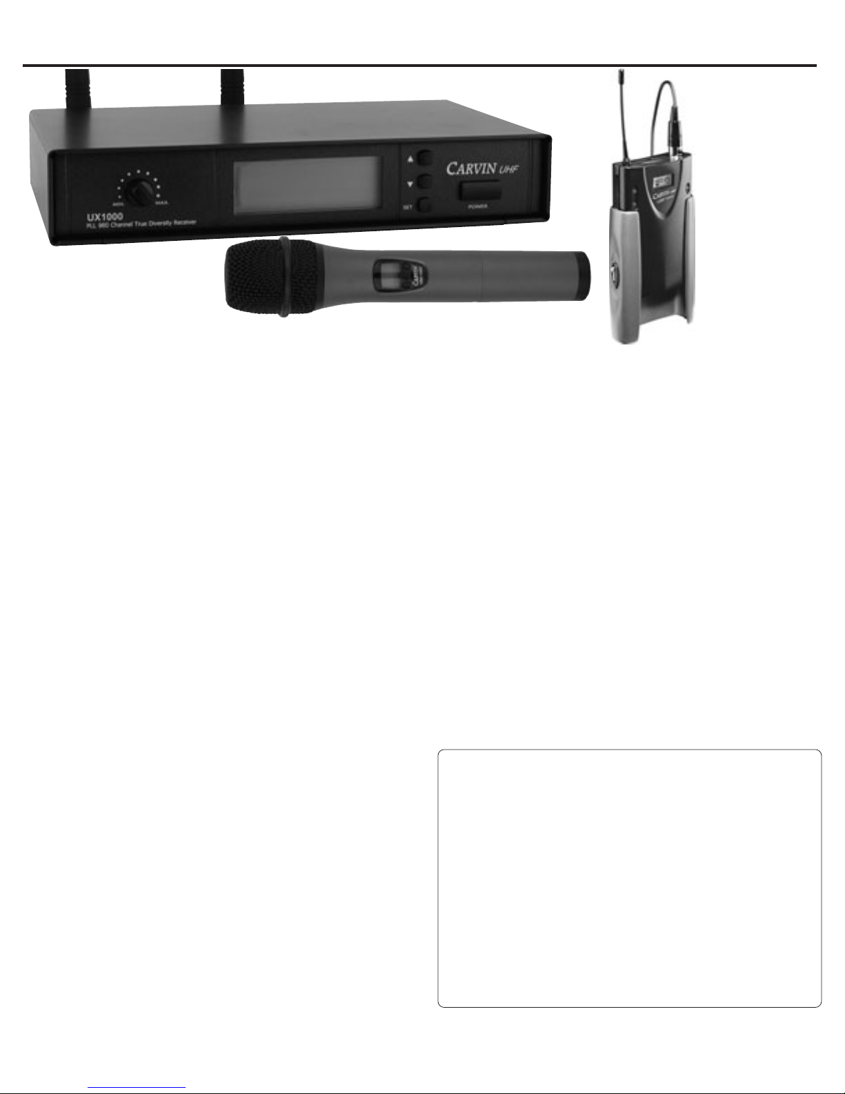
UX1000-MC, UX100BP
WIRELESS SYSTEMS
Congratulations on your purchase of the UX1000 SERIES Professional Wireless
System.
These systems include a receiver along with a handheld mic with
transmitter (UMC1000) or a belt-pack transmitter (UBP1000) depending on the
model purchased.The headworn mic (UX-HM2), cable for instrument (UXGT) and
lavaliere mic (UX-LP1) are all available as additional options to the UBP1000
belt-pack system.
The receiver features true UHF diversity reception. Two antennas feed two
completely independent RF receivers on the same frequency. Automatic logic
circuitry continuously compares and selects the superior signal to provide better
sound quality and reduce the possibility of interference and dropouts. Both the
transmitter and receiver have 960 user selectable channels, which can be grouped
into four groups. The receiver can be mounted in a standard 19" rack (1U) with
use of the optional UX-DR adapter.
The versatile UBP1000 belt-pack transmitter is designed for use with
condenser microphones as well as Hi-Z instrument pickups. Please note that in
multiple-system applications there must be one transmitter per receiver.
GETTING STARTED QUICKLY
If you’re like most new owners, you’re probably in a hurry to plug your wireless
system in and use it. Here are some brief instructions to get you going quickly.
With the wireless system unplugged and the unit turned off, complete the
following procedures:
1. CHANNEL CHECK
Check that both the transmitter and receiver are set
to corresponding channel. If multiple systems are used, each system must be
set to their own channel.
2. OUTPUT CONNECTIONS
There are two audio outputs on the back
of the receiver: balanced XLR and unbalanced 1/4”. Connect the appropriate
cables for your system.
3. POWER CONNECTIONS
Connect the included AC adapter to the DC
power input on the back of the receiver. Plug the adapter into a standard 120
volt 60 Hz AC power outlet.
4. RECEIVER POWER ON
Turn down the Volume control of the receiver as
well as the mixer. Switch on the receiver only. Do not switch on the transmitter.
The power indicator will light up even though the transmitter is not on.
5. BELT PACK SETTINGS
Connect the instrument cable or mic
to the Belt-pack. Set the rear gain switch to -20 for mic or 0 for instrument use.
Set the fine gain control to 12 o’clock. Reduce if distortion occurs.
HANDHELD MIC TRANSMITTER
UMC1000
Polar Pattern Unidirectional
RF Power Output 3 mW
Spurious Emissions Under federal regulations
Dynamic Range ≥100 dB
Battery AA 1.5v alkaline qty 2
Current Consumption 30 mA typical
Battery Life Approx. 25 hours
Dimensions 9.65” long, 2.10” dia.
Net Wt (no battery) 12.7 oz (360 grams)
Accessory Included mic clip
Warranty 90 days
BELT PACK TRANSMITTER UBM1000
Spurious Rejection < -60 dBC
Stability ± 0.005%
Frequency Deviation ± 48kHz
Battery AA 1.5v alkaline qty 2
S/N Ratio >100dB (1kHz-A)
Current Consumption 100mA typical
Dimensions 2.56” W x 4” H x 1” D
Net Wt (no battery) 2.8 oz (78 grams)
Warranty 90 days
6. BATTERY
Insert fresh AA alkaline batteries into the transmitter.
7. TRANSMITTER POWER ON
Switch the transmitter mic to
the “on” position.
8. SOUND CHECK
To do a sound check, gradually raise the level while
watching the AF level indicator. Increase the level until the AF level indicator
peaks. This indicates that maximum level without distortion has been reached.
On the belt pack adjust the AF level of the transmitter using the included
screwdriver.
For your records, record the following information.
Serial No._____________________ Invoice Date_______________
RECEIVING INSPECTION—read before getting started
INSPECT YOUR WIRELESS SYSTEM FOR ANY DAMAGE which may have occurred
during shipping. If any damage is found, please notify the shipping company and
CARVIN immediately.
SAVE THE CARTON & ALL PACKING MATERIALS. In the event you have to re-ship
your unit, always use the original carton and packing material.This will provide the bestpossible protection during shipment. CARVIN and the shipping company are not liable
for any damage cause by improper packing.
SAVE YOUR INVOICE. It will be required for warranty service if needed in the future.
SHIPMENT SHORTAGE. If you find items missing, they may have been shipped
separately. Please allow several days for the rest of your order to arrive before inquiring.
RECORD THE SERIAL NUMBER on the enclosed warranty card or below on this manual for
your records. Keep your portion of the card and return the portion with your name and
comments to us.
c
rev A
Page 3

UX1000 RECEIVER
FRONT PANEL FEATURES
1. POWER SWITCH
Depress to power the receiver.
2. UP BUTTON
Depress to increase the number and set the operation mode.
3. DOWN BUTTON
Depress to decrease the number and set the operation mode.
4. SET BUTTON
Depress to set up the operation mode.
5. LCD PANEL
Clearly displays the operation mode
6. VOLUME CONTROL
Adjusts the output audio level to your amp or mixer. If distortion occurs, reduce the level.
REAR PANEL FEATURES
7. DC POWER INPUT
Use AC power adapter, which supplies 12V DC.
8. UNBALANCED 1/4” AUDIO OUTPUT JACK
1/4” phone jack can be connected to an unbalanced input of a mixer.
9. BALANCED XLR AUDIO OUTPUT JACK
A standard XLR microphone cable can be used to connect the receiver output to a balanced
input on a mixer.
10. ANTENNA
Dual antenna for Diversity signal reception.
1. AF signal
2. RF signal
3. Display for GROUP mode
4. Display for LOCK mode
5. Display for set FREQ. mode
6. Frequency display
7. Diversity display (A or B receiver)
8. Battery display for the transmitter
9. Group channel display
LCD PANEL DISPLAY
UX1000 FRONT AND REAR RECEIVER PANEL CONTROLS
7
8
9
2
6
5
4
1
3
1. SETTING GROUP CHANNEL
DISPLAYED
A. GROUP NUMBER SET UP
Press the "SET" button for three seconds until "FREQ" shows up in the LCD display.
Press the "SET" button a 2nd time to display the frequency number. Press "UP" or "DOWN"
to increase or decrease the group number.
B. CHANNEL SET UP
After step A. press "SET" a 3rd time to display “CH”, press "UP" or "DOWN" to change
the CH number. Press "SET" again and the receiver will store the channel.
DISPLAYED
GROUP NUMBER SET UP
Press the "SET" button for three seconds until the "G" group number shows in the LCD.
Press the "SET" button a 2nd time to display the frequency number. Press "UP" or "DOWN"
to increase or decrease the group number.
CHANNEL SET UP
After the group set up press "SET" a 3rd time to display “CH”, press "UP" or "DOWN"
to change the “CH” number. Press "SET" again and the receiver will store the channel.
2. SETTING FREQUENCY
DISPL
Press the "SET" button for three seconds until "FREQ" shows up in the LCD display.
Press "UP" or "DOWN" to increase or decrease the frequency number. Press "SET" again
and the receiver will store the frequency.
DISPLAYED
Press the "SET" button for three seconds until the "G" group number shows in the LCD.
Press "SET" again and the frequency starts flashing.
Press "SET" until the "FREQ" shows use the "UP" or "DOWN" buttons to change the group
digit. Press "SET" again the receiver will store the channel.
3. SETTING LOCK-ON
DISPLAYED
Press "SET" button for three seconds until "FREQ" shows in the LCD. Press "SET" again
and the Group number starts flashing. Press "SET" again until the frequency starts
flashing then press "SET" to start the lock-on setting.
Press "UP" button for lock-on mode and "DOWN" button for lock-off mode. Re-press
"SET" and the lock function will store.
DISPLAYED
Press "SET" button for three seconds until the Group number shows. Re-press "SET"
and the frequency starts flashing. Press "SET" again till "FREQ" show up, re-press "SET"
button till "LOCK OFF" starts flashing then you can proceed the lock-on setting.
(2) Press "UP"" button for lock-on mode and "DOWN" button for lock-off mode.
Re-press "SET" button the lock function will store.
4. RELIEVED LOCK-ON
Press "SET" button three seconds till "LOCK ON" show up, then press "DOWN" button
plus "SET" button to store the lock-on relieved.
5. Pressing any button will display "LOCK ON" during Lock On mode. This setting remains
until it is disabled. Turning the unit off will not disable the Lock On mode.
GROUP
FREQ.
GROUP
FREQ.
GROUP
FREQ.
10
UX-DR DUAL RACKMOUNT ADAPTER With the optional UX-DR adapter, you can mount
one or two receivers. Remove the front panel of the mounting adapter to mount the
second receiver.
Page 4

UP
DOWN
SET
UX-HM2
UMC1000 HAND HELD MIC
1. BATTERY INSTALLATION FIG. C
While holding the higher part of the transmitter body, unscrew the handle. Install fresh
AA alkaline batteries. Replace the handle and turn clockwise until tight.
2. POWER ON FIG. D
Switch to POWER ON position.
3. MUTE SWITCH
FIG. D
Used to mute audio without losing RF connection.
4. UMC1000-ID 7 COLOR CODED RINGS FIG. E
Use the UMC1000-ID 7 color coded rings to identify multiple microphones in use.
Each color can correspond to a different wireless channel.
UBP1000 BELT-PACK TRANSMITTER
1. BATTERY INSTALLATION FIG. A
Alkaline AA batteries are recommended. Hold on to the belt clip buttons to release battery
tray. Insert fresh AA alkaline batteries. Slide the belt clip back until it locks.
BELT PACK SET-UP FIG. A
1. METAL CASE & BELT CLIP
The metal case provides extra protection for the transmitter and the plastic belt clip keeps
it safe and at your side. Hold on to the belt clip buttons and slide the transmitter up to access
the front and rear controls.
2. SENSITIVITY FIG. B The transmitter's sensitivity controls are located on the rear. Use
the mini screwdriver to first set the Sensitivity switch to 0 for instruments or -20 for microphones. Use the mini screwdriver to make fine gain adjustments to the Sensitivity AF Gain
for optimal transmitter volume. Decrease the gain if distortion is heard.
3. INPUT CONNECTOR
The mini XLR input jack will connect a lavaliere mic, headset mic, or instrument cable to
the transmitter. Line up the notches on the side of the jack and plug. Push in until cable
locks into the jack. To unplug the mini XLR cable, press the round release button on the
cable to unlock it from the jack.
4. TRANSMITTER ON SWITCH
Turn the receiver volume down before turning the transmitter power ON. The transmitter
ON-OFF switch is located at the top of the unit.
5. FREQUENCY ADJUSTING
Hold "SET" button for 3 seconds to activate frequency.
Once you see "MHZ" blinking, you are ready to select your desired frequency by using
"UP" and "DOWN" buttons.
Press the "SET" button again to store your changes.
6. TO ACTIVATE "LOCK MODE"
Hold on to "UP" button for 3 seconds to activate "LOCK MODE", press again to unlock.
Transmitter
ON/OFF Switch
Push round button
to release cable
LCD Display
SET Button(1)
UP Button
Down Button
Hold to release
battery tray
click sides
battery case
slides down
replace
batteries
push up to
access front and
rear controls
UX-HM2 HEADSET MIC
Connect the mic cable to the transmitter's mini XLR input jack. Place the mic on vocalist head with the headband resting comfortably on the rear of the neck. Keep the mic
a minimum of 2 inches from the mouth. Adjust the mic position to minimize air from
hitting the mic.
UX-LP1 LAVALIERE MIC
Connect the Lavaliere mic cable to the transmitter's mini XLR input jack. Clip the mic
to a shirt. For optimum sound, position the mic as close to the mouth with the top of
the mic facing up. Test out various positions along the center of the chest to determine
the ideal mic placement. This may vary from person to person as each voice projects uniquely.
UXGT INSTRUMENT CABLE
Connect the cable to the belt-pack transmitter’s mini
XLR input jack. Plug the 1/4” connector into a guitar. Turn the receiver volume down
before turning the transmitter power ON.
UX-LP1
UXGT
PROGRAMMING HAND HELD MIC FIG. F
1. SETTING GROUP CHANNEL
GROUP SET UP
Press "SET" button for three seconds until the "MHZ" shows and then
re-press "SET" until the group digit shows. Now you can
press "UP" or "DOWN" button one sec. to increase or decrease group
number
CHANNEL SET UP
Follow the GROUP SET UP procedures, then press "SET" again and the frequency displays,
press "UP" or "DOWN" to increase or decrease the frequency.
Press "SET" to store the mic frequency.
GROUP DISPLAYED
Press "SET" for three seconds until the Group digit shows. Then re-press "UP" or "DOWN"
button to increase or decrease the group number.
Press "SET" again and the frequency displays. Press "UP" or "DOWN" to increase or decrease
the frequency. Press "SET" again and the mic will store the frequency.
FIG. A
FIG. B
FIG. C
unscrew the
handle to
replace
batteries
POWER
FIG. D
MUTE
FIG. E
UMC1000-ID color coded rings
FIG. F
Antenna
Sensitivity
-20 -6 0
GAIN
Set to 0 for
instruments
Set to -20 for mics
fine gain
settings
 Loading...