

Page 1

TRx3810A VELA™ VERTICAL ARRAY ELEMENT
BUILT IN THE
VELA™
The TRx3810A-VELA™ is the go-to cabinet for small and large scale
sound systems. Each VELA™ element is a full range stand-alone system,
but is also the key component for creating large scale systems. The long,
thin cabinets are designed to link together so just a few cabinets achieve
a full spectrum line array output. VELA™ is also right at home at smaller
events with one or two speakers on a stand, and turning on the Enhanced
Bass feature creates a virtual sub with extended low frequency response.
For fuller sub bass requirements, add one or more TRx3018A powered
18-inch subwoofers. For larger venues flying three to four VELA™ elements per side, add muliple TRx2218A (active), TRx2218b or TRx3218
dual 18-inch subwoofers as needed.
ACTIVE 2500W SYSTEM
The
TRx3810A-VELA™ active module is a 2500W 3 channel power
amp with two channels bridged for 1500W to the dual 10-inch Neodymium
speakers and a seperate 1000W channel for the eight driver column array.
The DCM power amp technology is mounted in a fan ventilated, internally
sealed aluminum structure for solid construction and durability.
The internal X-Drive™ DSP maximizes performance output and protection with limiters, alignment delay, parametric EQ and up to 48dB/oct
crossover filters.
CONNECT, SELECT AND PLAY
The internal X-Drive™ DSP processor maximizes performance output.
All you need to do is select a preset for 1, 2, or 3-4 cabinets and play.
One and two cabinet programs also feature EQ contour selections: Live
1, Live 2, Playback 1, or Playback 2, and turning on the Enhance Bass
feature creates a virtual sub at lower levels.
EXPANDING THE VELA™ SYSTEM
VELA’s™ unique SlideLock™ hardware slides together and locks with
just two quick release pins to secure the cabinets for stacking or flying
quickly and easily. When two cabinets are linked the array ef fect extends to
the 10-inch drivers adding lower mid frequencies to the column projection.
Hang up to 4 cabinets per side using the available SlideLockTBAR™.
In a 4 cabinet hang the array effect develops from a 10-foot long front and
the long distance array projection reaches well into the 150Hz range. The
VELA™ system advantage is fuller audio spectrum array projection with
fewer cabinets required.
performance output when you select the preset for the number of cabinets.
The internal X-Drive™ DSP processor maximizes
USA
USER MANUAL
X-Drive™ DSP controlled power
RECEIVING INSPECTION—read before getting started
INSPECT YOUR UNIT FOR DAMAGE which may have occurred during shipping. If damage is found
please notify the shipping company and CARVIN immediately.
SAVE THE CARTON & ALL PACKING MATERIALS. In the event you have to re-ship your unit, always
use the original carton and packing material. This will provide the best possible protection during shipment. CARVIN and the shipping company are not liable for any damage caused by improper packing.
SHIPMENT SHORTAGE. If you find items missing, they may have been shipped separately. Please
allow several days for the rest of your order to arrive before inquiring.
RECORD THE SERIAL NUMBER on the enclosed warranty card and below for your records. Keep
your portion of the card and return the portion with your name and comments to us.
SERIAL #_________________________ INVOICE #___________________ DATE___________
integrated SlideLock™ hardware
16262 WEST BERNARDO DRIVE SAN DIEGO, CA 92127
800-854-2235 CARVINAUDIO.COM
Page 2
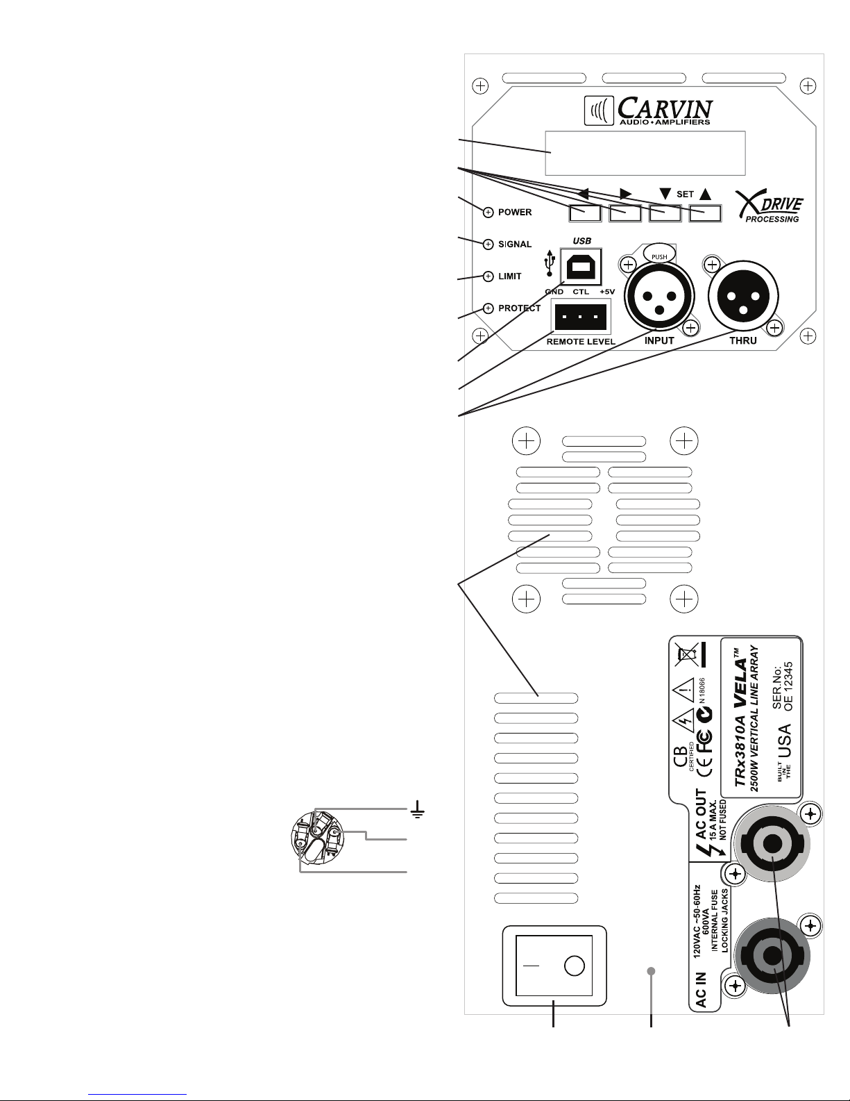
CONTROLÊPANELÊFEATURES
L
1. POWER SWITCH (reset)
Push the left portion of the power switch to turn the system on. If the
blue POWER indicator is on but there is no sound or the Protect LED is
on, reset, turn the power off for 10 seconds and then turn it back on. If
the problem persists, check for no input signal or a blocked fan intake.
2. POWER LED
The POWER LED indicates the unit is turned on and functioning
properly.
3. SIGNAL LED
The SIGNAL LED indicates there is a signal present at the INPUT
XLR.
4. LIMIT LED
The LIMIT LED indicates that the maximum output of the system
is being reached. A flashing LIMIT LED is acceptable, the DSP will
reduce peaks to prevent amp clipping. However, if the LIMIT LED is
continuously ON, reduce the level going in to the INPUT XLR. As with
any system, reduce the volume if distortion is heard.
5. DIGITAL DISPLAY
The bright green LED DIGITAL DISPLAY will display various information about the system and its settings. To change settings use the
UP/DOWN (SET) and LEFT/RIGHT buttons.
6. SETTING BUTTONS (SET)
Use the UP and DOWN (SET) buttons to load different presets for
speaker configurations or to increase or decrease settings. The LEFT
and RIGHT buttons will allow selection of the different settings.
7. INPUT/THRU XLR CONNECTORS
Connect the INPUT XLR to a signal source such as the output of a
mixer. The THRU XLR can be connected to more TRx3810A VELA
cabinets, powered subwoofers or other units.
8. REMOTE LEVEL (MUTE) CONNECTOR
This is a terminal block connector with 5 volt control of volume, typically used in permanent installations. Short the CTL and GND pins
to MUTE.
9. USB PORT
The USB port is for updating system firmware such as new presets.
10. PROTECT LED
The PROTECT LED indicates one of the protection circuits has
activated and no sound will be heard from the amp. To reset the
amp, turn the power off for about 10 seconds, then turn it back ON.
If the PROTECT LED stays lit for more than 5 seconds, check for a
blocked fan intake.
11. FAN INTAKE / EXHAUST VENTS
The power module features a variable speed fan, which runs silent
at low speeds. Make sure the fan intake and exhaust vents are free
from blockage at all times.
12. AC IN / AC OUT POWER JACKS
The AC IN / AC OUT use the Neutrik™ PowerCon™ A-Type and
PowerCon™ B-Type connectors.
AC IN accepts Neutrik™ # NAC3FCA.
AC OUT accepts Neutrik™ # NAC3FCB.
A detachable power cord kit is supplied to
connect the AC IN to a standard wall outlet.
The AC OUT connector can be used with a NAC3FCA to NAC3FCB
cable to power other units such as another TRx3810A, or up to two
devices with a total rating of 15A or less. Other limiting factors include
the breaker rating for the AC line you are plugging into, wire type and
(if used) generator capacity. No attempt should be made to use the
amp without the ground connected.
13. FUSE
The FUSE is located internally near the AC input. To check or replace,
first remove the power cord. Then remove the amp module from the
speaker enclosure and remove the front panel to access the fuse.
The fuse # is a 250V Slow Blow rated at 10A.
N
10
11
5
6
2
3
4
9
8
7
1
13
12
Page 3
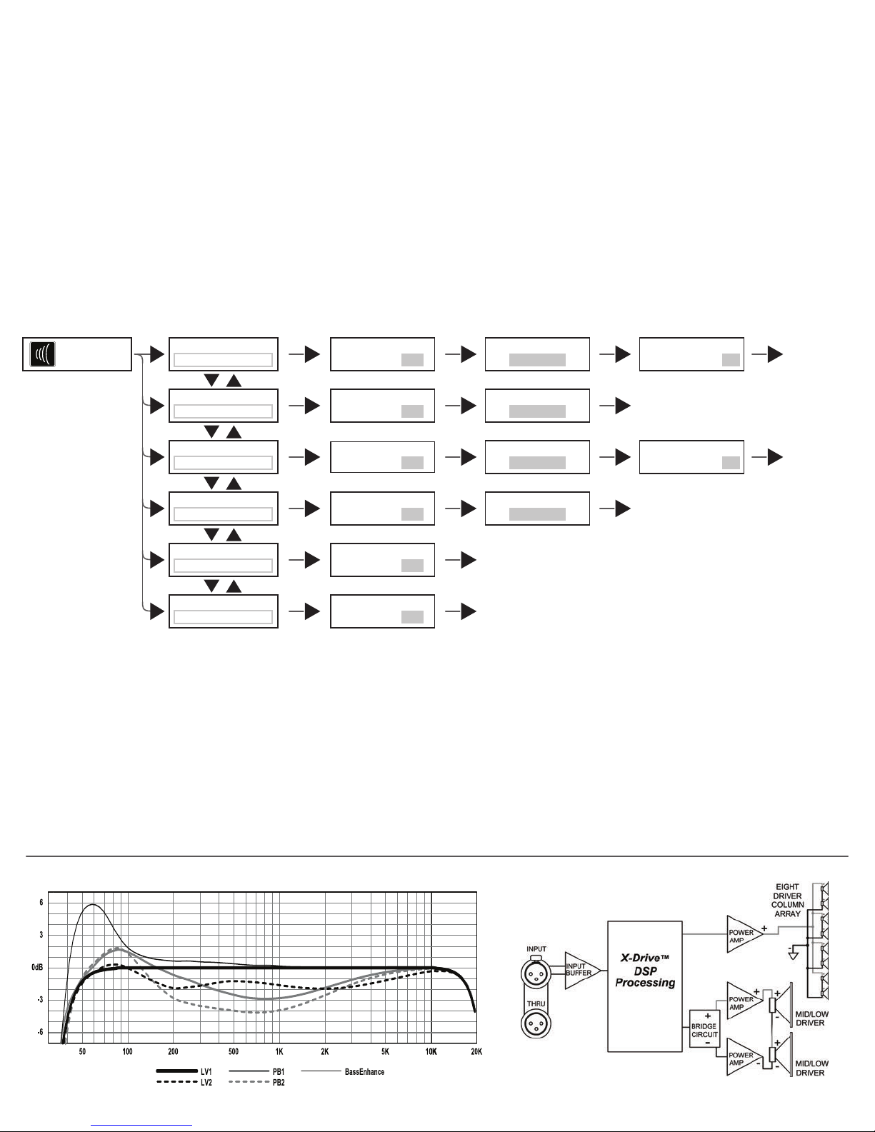
SETTINGSÊMENU
To select which screen is shown, use the LEFT and RIGHT buttons t u.
Use the UP and DOWN buttons pq to change the Preset or to change the value of the settings shown in grey.
Settings are automatically saved within each Preset.
TRx3810A Preset screen:
This selection will load different settings for the TRx3810A - VELA™. These settings are optimized for the number of VELA™ cabinets
to be linked in a single column and if there will be subwoofers as part of the system. The ExtSub85Hz settings add a 85Hz high pass
filter to allow more efficient power from the VELA™ when adding subs to the system. Set subwoofer crossovers to 85Hz (low pass).
Single FullRange: One cabinet per side, no subwoofers in system. Full range.
SingleExtSub85Hz: One cabinet per side, when using subwoofers. 85Hz, 24dB/oct. Butterworth high pass filter.
Dual FullRange: Two cabinets per side, no subwoofers in system. Full range.
Dual ExtSub85Hz: Two cabinets per side, when using subwoofers. 85Hz, 24dB/oct. Butterworth high pass filter.
3-4 Full-Range: 3-4 cabinets per side, no subwoofers in the system. Full range.
3-4 Ext Sub 85Hz: 3-4 cabinets per side, when using subwoofers. 85Hz, 24dB/oct. Butterworth high pass filter.
(welcome screen)
Carvin
TRx3810A
Select one of the
6 presets
TRx3810A Preset:
Single FullRange
TRx3810A Preset:
Single ExtSub85Hz
TRx3810A Preset:
Dual FullRange
TRx3810A Preset:
Dual ExtSub85Hz
TRx3810A Preset:
3-4 Full-Range
TRx3810A Preset:
3-4 Ext Sub 85Hz
Set the Sensitivity
within each preset
TRx3810A v1.2b
Sensitivity: 1.4v
TRx3810A v1.2b
Sensitivity: 1.4v
TRx3810A v1.2b
Sensitivity: 1.4v
TRx3810A v1.2b
Sensitivity: 1.4v
TRx3810A v1.2b
Sensitivity: 1.4v
TRx3810A v1.2b
Sensitivity: 1.4v
Choose a Contour
in Single or Dual presets:
TRx3810A Contour:
Live 1
TRx3810A Contour:
Live 1
TRx3810A Contour:
Live 1
TRx3810A Contour:
Live 1
back to the
welcome screen
back to the
welcome screen
Set Enhance Bass On or Off
in Single or Dual FullRange:
TRx3810A
Enhance Bass: Off
back to the
welcome screen
TRx3810A
Enhance Bass: Off
back to the
welcome screen
back to the
welcome screen
back to the
welcome screen
SENSITIVITY: 1.0v, 1.2v, 1.4v, 2.0v (Vrms)
Sets the overall level required from your source to the INPUT XLR to reach maximum volume. The factory setting is 1.4v.
A lower setting will increase volume, a higher setting will decrease volume.
CONTOUR EQ: (Available in SINGLE and DUAL cabinet presets) EQ contours: Live 1, Live 2, Playback1, Playback2
The Contour EQ setting offers four different equalization presets. The preset names are based on the type of material to be played,
however select which one sounds best for your music. The factory flat setting is “Live 1”. (see the contour curves in the chart below)
ENHANCE BASS: (Available in SINGLE and DUAL cabinet FullRange presets): Off, On
The Enhance Bass feature allows lower frequencies to be reproduced by the VELA™, creating a virtual subwoofer at lower volumes.
Low frequency response is extended by 15Hz and boosts the 50-80Hz range. The effect will be reduced at the highest volumes to
stay within the limits of the system but still adds depth at less than maximum levels. (see the BassEnhance curve in the chart below)
Contour curve presets (DSP output)
TRx3810A Block Diagram
Page 4

VELA™
PACKAGE SYSTEMS
• High level, dynamic sound for live performances
• SlideLock™ hardware and DSP presets for quick set up
• Vertical design for a long array from a few cabinets
• Systems scale down for smaller gigs or multiple rigs
• Design overcomes difficult acoustic situations
• Amazing clarity and intelligibility
• Installation or portable use
• Built in the USA
VELA2
• 2 TRx3810A
• 2 TRx3018A 1x18” powered subs
• 2 - SS4 Adjustable Poles
• 2 - C10XLR cables
VELA4
• 4 TRx3810A
• 4 TRx3018A 1x18” powered subs
• 2 PowerCon
• 6 - C3XLR cables
10,000w
VELA™
20,000w
VELA™
™
link cables
elements
elements
VELA8
• 8 TRx3810A
• 16 TRx2218A dual 18” powered subs
• 2 SlideLockTBAR flyware brackets
• 6 PowerCon
• 6 - C3XLR cables
• 5 - C10XLR cables
60,000w
VELA™
™
link cables
elements
Page 5

SETUP EXAMPLES
SETUPS
VELA 2 SYSTEM EXAMPLE
15A
circuit
TRx3810A
Left
Left Right
Left
Mixer
TRx3018A sub
2nd
15A
circuit
Right
TRx3810A
Right
TRx3018A sub
VELA 4 or VELA 8 SYSTEM EXAMPLE
TRx3810A TRx3810A
for VELA 8 system,
link more TRx3810A’s
Left Right
for VELA 8 system,
link more TRx3810A’s
Left Right
Mono Mono Mono Mono
chain AUX or MONO signal
through all subs
15A
circuit
Left
Right
TRx3018A or TRx2218A subs
15A
circuit
TRx3810A
15A circuit
for each pair
Mixer
AUX
or
MONO
15A circuit each sub
TRx3810A
15A circuit
for each pair
Page 6

STACKING
About the SLIDELOCK™ system:
The integrated SlideLock™ plates on
each end of the VELA™ slide together
from front to rear and are secured with
just two quick-release pins.
Connecting two VELA cabinets:
1. STAND the first VELA cabinet on a firm,
level surface.
2. LIFT the second cabinet so it’s
BOTTOM FRONT feet sit on the TOP
REAR edge of the lower cabinet.
3. SLIDE the top cabinet forward so the
SlideLock hardware interlocks. (note:
the cabinets are interlocked when tilting
the top cabinet side to side moves both
cabinets as one.)
4. SECURE the SlideLock with the two
quick release pins: On the back of the
cabinets, line up the holes in the upper
and lower plates by sliding the top cabinet. Insert the pins as shown. Pressing
the button on the end of the pin allows
the pin to slide in or out.
VELA on a standard pole stand
VELA™ mounts to
SlideLock™ equipped
subwoofers.
Page 7

SUSPENSION
About the SlideLockTBAR™:
The SlideLockTBAR™ provides a hang
point to suspend up to four VELA™
cabinets inline from a 5/8” shackle and
standard rigging such as a chain hoist.
The hang angle can be adjusted depending on the chioce of shackle attach point.
Connecting the SlideLockTBAR:
1. SLIDE the SlideLockTBAR into the
SlideLock™ plates on the top of the VELA.
The TBAR should extend about 3.5 in.
(90mm) off the rear of the VELA cabinet.
2. SECURE the SlideLockTBAR with the
two quick release pins: Line up the holes
in the top rear of the VELA hardware
with the holes in the SlideLockTBAR
hardware. Insert the two pins as shown.
Pressing the button on the end of the pin
allows the pin to slide in or out.
Tilt down Tilt up
3. ADD MORE VELA cabinets to the
bottom of the first, securing each one
with two quick release pins as they are
attached (see the ST ACKING procedure).
If more that two VELA are attached, use
the chain hoist to lift them up to the proper
level for attaching. The maximum number
to safely hang inline is 4 cabinets.
4. SET THE ANGLE of the hang by
selecting a different shackle location. The
fourth hole from the front will be a vertical
hang. Attaching the shackle to the rear will
tilt the hang down. Attaching the shackle
to the front will tilt the hang upward.
Add SlidelockTBAR™ for flying and
secure with the quick release pins
Page 8

RISK OF ELECTRIC SHOCK
SPECIFICATIONS
TRx3810A - VELA™
System Type: Active, 2500W X-Drive™ processed
Vertical Array Element
Freq. Response: 60 Hz – 16kHz (-10dB),
70 Hz – 14kHz (-3dB)
with Bass Enhance: 15Hz < normal
Coverage Pattern: 100H x 40V single cabinet
Crossover Type: Active DSP Bi-amp
Crossover Frequency: 400 Hz
DSP Contours: Live 1, Live 2, Playback 1, Playback 2
(in Single and Dual presets)
Power: 2500W 20ms burst (2000W LF/500W HF)
1600W RMS (1250W LF, 350W HF)
Input Sensitivity: 1.0, 1.2, 1.4, or 2.0 Vrms settings
Maximum Input signal: +12dBu
Maximum SPL: 129dB single cabinet
LF Driver: 2x 10-inch Neodymium, 2.5-inch VC
MF/HF Driver: 8x 3.5-inch
Enclosure: Premium Russian Baltic Birch
Finish: Black DuraTec™
Grill: Black powder coated steel
Transport: 4 Recessed Steel Handles
Suspension: 12 captive 3/8in-16 nut fly pts.
SlideLock™ rigging
Bottom 1-3/8-inch Pole Cup
Connectors: Signal In/Thru: XLR female/XLR male
Remote Level/Mute: Terminal block
AC IN/OUT: Neutrik™ PowerCon™, A-T ype/B-T ype
AC Power Requirement: TRx3810A: 120VAC 50/60Hz 600VA
TRx3810A-E: 230VAC 50/60Hz 600VA
Dimensions, H x W x D: 31.875 in x 12 in x 14.75in
(810 mm x 310 mm x 375 mm)
Net Wt: 66 lb (30 kg) with Flyware
Origin: Built in the USA
Accessories: SlideLockTBar Top-bar kit 3 lb (1.5kg)
TCSHK58 5/8” Shackle 1.3 lb (0.5kg)
CVTRX3810 vinyl backed nylon cover
CBTRX3810 padded cover
LIMITED WARRANTY
Your Carvin Audio loudspeaker is guaranteed against failure for 5 YEARS unless otherwise
stated. Carvin will service and supply all parts at no charge to the customer providing the unit
is under warranty. Shipping costs are the responsibility of the customer. CARVIN DOES NOT
PAY FOR PARTS OR SERVICING OTHER THAN OUR OWN. A COPY OF THE ORIGINAL
INVOICE IS REQUIRED TO VERIFY YOUR WARRANTY. Carvin assumes no responsibility
for horn drivers or speakers damaged by this unit. This warranty does not cover, and no liability
is assumed, for damage due to: natural disasters, accidents, abuse, loss of parts, lack of reasonable care, incorrect use, or failure to follow instructions. This warranty is in lieu of all other
warranties, expressed or implied. No representative or person is authorized to represent or
assume for Carvin any liability in connection with the sale or servicing of Carvin Audio products.
CARVIN SHALL NOT BE LIABLE FOR INCIDENTAL OR CONSEQUENTIAL DAMAGES.
MAINTAINING YOUR EQUIPMENT
Avoid spilling liquids or allowing any other foreign matter inside the unit. The panel of your unit
can be wiped with a dry or slightly damp cloth in order to remove dust and bring back the new
look. As with all pro gear, avoid prolonged use in caustic environments (salt air). When used
in such an environment, be sure the amplifier is adequately protected.
SERVICE:
In the USA, please go to www.carvinaudio.com
under “SUPPORT” click on “REPAIR INFORMATION”
Outside the USA: contact your dealer or go to http://www.carvinaudio.com
click on “DEALERS” for your nearest service center.
Include a written description of the problem with serial number and date of purchase.
This symbol is intended to alert
the user to the presence of
uninsulated “dangerous voltage” within the product’s enclo-
sure that may be of sufficient
magnitude to constitute a risk of electric
shock to persons.
IMPORTANT! FOR YOUR PROTECTION, PLEASE READ THE FOLLOWING:
WATER AND MOISTURE: Appliance should not be used near water (near a bathtub, washbowl, sink,
laundry tub, in a wet basement, near a swimming pool, etc). Care should be taken so that objects do not fall
and liquids are not spilled into the enclosure through openings.
POWER SOURCES: The product should be connected to a power supply only of the type described in
the operating instructions or as marked on the appliance.
GROUNDING OR POLARIZATION: Precautions should be taken so that the grounding or polarization
is not defeated.
POWER CORD PROTECTION: Power supply cords should be routed so that they are not likely to be
walked on or pinched by items placed upon or against them, paying particular attention to cords at plugs.
SERVICING: The user should not attempt to service the appliance beyond that described in the operating
instructions. All other servicing should be referred to qualified service personnel.
FUSING: If your unit is equipped with a fuse receptacle, replace only with the same type fuse. Refer to
replacement text on the unit for correct fuse type.
CAUTION
RISK OF ELECTRIC SHOCK
DO NOT OPEN
This symbol is intended
to alert the user to the
presence of important
operating and maintenance
(servicing) instructions
in the literature accompanying the
appliance.
SAFETY INSTRUCTIONS (EUROPEAN)
The conductors in the AC power cord are colored in accordance with the following code.
GREEN & YELLOW—Earth BLUE—Neutral BROWN—Live
U.K. MAIN PLUG WARNING: A molded main plug that has been cut off from the cord is
unsafe. NEVER UNDER ANY CIRCUMSTANCES SHOULD YOU INSERT A DAMAGED OR
CUT MAIN PLUG INTO A POWER SOCKET.
CAUTION
RISK OF ELECTRIC SHOCK
REFER SERVICING TO QUALIFIED SERVICE
PERSONNEL! THIS UNIT CONTAINS HIGH
VOLTAGE INSIDE!
VELA™ TRx3810A SINGLE CABINET FREQUENCY RESPONSE
76-03810A122216
 Loading...