

Page 1
CARVIN ENGINEERING DATA
OPERATING MANUAL
12340 World Trade Drive, San Diego, CA 92128
(619) 487-1600 (800) 854-2235
www.carvin.com
Congratulations on your purchase of the SX amplifier . Carvin has been building guitar amplifiers
since 1949. They have been used by top professionals like; Frank Zappa, Steve Vai, Craig Chaquico,
Allan Holdsworth, Larry Carlton, Chet Atkins and other great musicians. Spend time with your
new combo and get to know it’s many sounds.
TECHNICAL DESIGN OF THE SX-DSP AMP
Designing the new SX meant incorporating the legendary Carvin Tube Technology™, DIGITAL effects,
and modern tone shaping technology, into a compact, rugged unit.
DIGITAL SIGNAL PROCESSING (DSP)
The SX-AMP is equipped with 16 of our favorite presets including chorus, flange, reverbs and delays, especially designed to compliment the guitar. Just turn the SELECT control to any of the 16 positions and increase
the LEVEL control to the desired mix volume, and enjoy the crisp, lush sound of DSP, without the complications of an external processor.
TUBE TECHNOLOGY™ OVERDRIVE CIRCUIT
Simulating both the smoothness and dynamics of overdriven vacuum tubes and using the reliability
of solid state technology has been a design goal of virtually every amp manufacturer in the business.
The SX Series truly captures the essential tone and character of tube distortion, thanks to Carvin’s innovative Tube Technology™.
CLEAN CHANNEL
The equalization of the clean channel is designed to offer clarity to your instrument. Special mud-cutting circuits eliminate the unwanted sounds in the 700 Hz range which normally take away the tone definition of your instrument. You will also take notice of the channels PRESENCE control which adds acoustic
voicing to your instrument. This control boosts only the guitars very highest harmonics which are in
the 10k Hz range instead of the normal 3K Hz of a bright switch. This control may not seem very effective, but it adds a glassy tone to your sound.
TONE CONTROLS
Many amps use passive EQ systems which allow “boost” only.The wide tonal range of the SX amp comes
from active
BASS, MID and TREBLE tone controls. Take full advantage by setting them where they sound
best. These controls will not affect or color your sound when set at extreme settings, nor do they interact
with each other. The frequency of the bass control is set at 100 Hz while the mid control is set at 1.5 kHz.
The treble control is set high, at 8k Hz giving the SX it’s dynamic highs. Presence is set to give the amp
that extra “edge”, assuring that you can make yourself heard in the mix. Another filter rolls off extreme
lows preventing premature overloading of the speaker at higher volumes.
REVIEWS
Craig Anderton says “ The reason I find the Carvin SX amps so attractive is because you can get clean
sounds - clean enough to serve as a recording amp in the studio - as well as some of the sweetest distortion sounds I’ve ever heard from a solid state amp. It’s no small feat to please me in that respect; remember I’ve spent a lot of my adult life designing fuzzes to get the sound I want, since conventional fuzzes
sound too rough for my tastes. Carvin’s distortion circuit though is exceptional. A lot of folks claim to
give a tube sound; frankly, the Carvin sounds better than a lot of the tube circuits I’ve used - it’s almost
like the SX produces an idealized tube sound rather than a real tube sound”.
Pete Prown from Guitar Shop Magazine says “.. One particularly impressive-sounding transistor job is
Carvin’s SX100, which also sports an impressive price tag...The SX100 offers a surprising wallop of crunch.
Using the Overdrive knob, a player can dial in how much gain they want and, believe us, there’s a lot in
there. Turn that sucker up to 3 o’clock and you’ll get a nice, fat distortion—not that kind of crappy , paper thin distortion that you find on many transistor boxes—but a meaty crunch... Compare this fine overdrive
with the amp’s surprisingly low price and you’ll see why we wanted to take a look at this small beast...
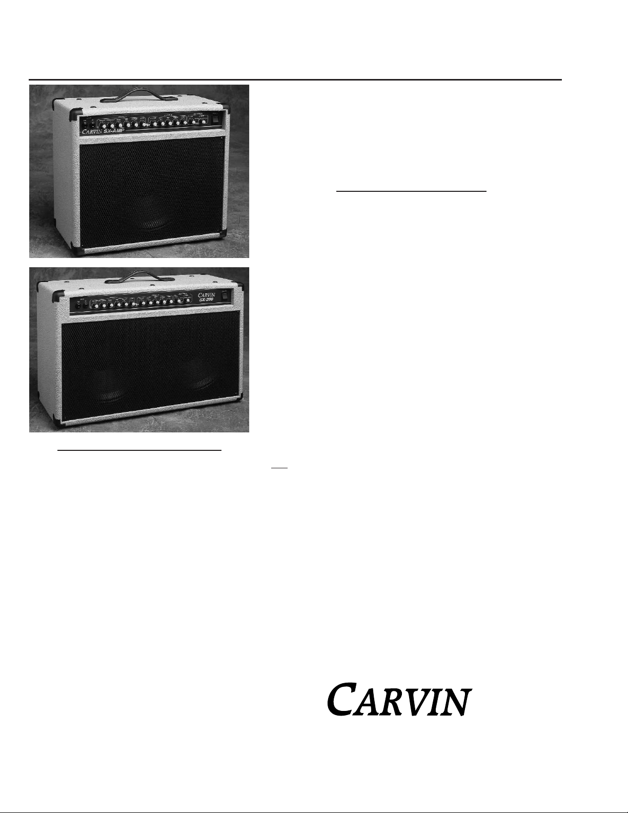
SX100D
For your records, you may wish to record the following information.
Serial No._____________________ Invoice Date_______________
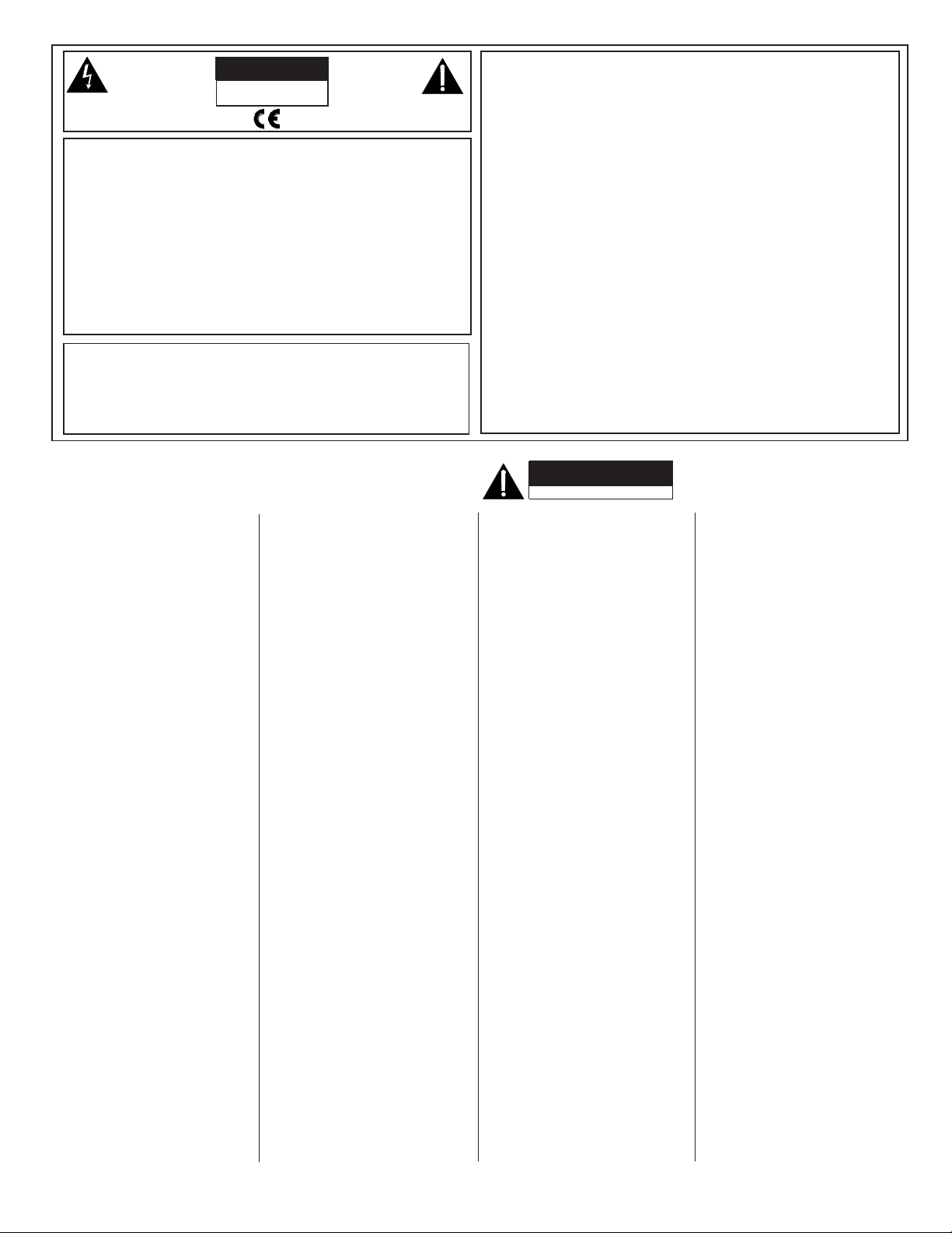
SX200D
RECEIVING INSPECTION—read before getting started
INSPECT YOUR AMP FOR ANY DAMAGE which may have occurred during shipping. If any damage is
found, please notify the shipping company and CARVIN immediately.
SAVE THE CARTON & ALL PACKING MATERIALS. In the event you have to re-ship your unit, always use
the original carton and packing material. This will provide the best possible protection during shipment.
CARVIN and the shipping company are not liable for any damage caused by improper packing.
SAVE YOUR INVOICE. It will be required for warranty service if needed in the future.
SHIPMENT SHORTAGE. If you find items missing, they may have been shipped separately. Please
allow several days for the rest of your order to arrive before inquiring.
RECORD THE SERIAL NUMBER on the enclosed warranty card or below on this manual for your records.
Keep your portion of the card and return the portion with your name and comments to us.
SX-100D & SX-200D CHORUS
COMBO GUITAR AMPS
MODEL SX100D & SX200D COMBO SPECS:
Speakers: BR12 British Series 12” spks
RMS Power: 100 watts @8ohms
Output Impedance: 4-16ohms
Power Amp: THD: Less than 0.1% @ 50%
Input Impedance: 1 Meg ohms
Channels: 2—switching
Tone Controls: BASS: 100Hz
Overdrive Channel MID: 1.5k Hz
TREBLE: 8k Hz
PRESENCE:8k Hz
Clean Channel BASS: 80Hz
MID: 1.5k Hz
TREBLE: 8k Hz
PRESENCE:12k Hz
Ch 1 Sensitivity: 1mV for clipping
Ch 2 Sensitivity: 75mV for full output
Line Out: 1.5 VAC @ full power
USA Model: 120VAC, 130VA
USA Fuse: 2A 250V slow blow, 5x 20mm
Export Model: 230VAC, 130VA
Export Fuse: 1A 250V slow blow, 5x 20mm
Cabinet Size: SX100: 19.5W x 10.25D x 17.5”
SX200: H26W x 10.25D x 17.5”H
Cabinet: 7-ply poplar wood
Net Weight: SX100: 30 lbs SX200: 40 lbs
Warranty: One Year
Options: FS22 footswitch,
CV211 cover SX100
CV3212 cover SX200
76-10200 797
Page 2
CAUTION
RISK OF ELECTRIC SHOCK
DO NOT OPEN
SAFETY INSTRUCTIONS (EUROPEAN)
The conductors in the AC power cord are colored in accordance with the following code .
GREEN & YELLOW—Earth BLUE—Neutral BROWN—Live
U.K.MAIN PLUG WARNING: A molded main plug that has been cut off from the cord is
unsafe. NEVER UNDER ANY CIRCUMSTANCES SHOULD YOU INSERT A D AMAGED
OR CUT MAIN PLUG INTO A POWER SOCKET.
IMPORTANT! FOR YOUR PROTECTION, PLEASE READ THE FOLLOWING:
WATER AND MOISTURE: Appliance should not be used near water (near a bathtub, washbowl,
kitchen sink, laundry tub, in a wet basement, or near a swimming pool, etc). Care should be taken
so that objects do not fall and liquids are not spilled into the enclosure through openings.
POWER SOURCES: The appliance should be connected to a power supply only of the type described
in the operating instructions or as marked on the appliance.
GROUNDING OR POLARIZATION: Precautions should be taken so that the grounding or polarization means of an appliance is not defeated.
POWER CORD PROTECTION: Power supply cords should be routed so that they are not likely
to be walked on or pinched by items placed upon or against them, paying particular attention
to cords at plugs, convenience receptacles, and the point where they exit from the appliance.
SERVICING: The user should not attempt to service the appliance beyond that described in the
operating instructions. All other servicing should be referred to qualified service personnel.
FUSING: If your unit is equipped with a fuse receptacle, replace only with the same type fuse.
Refer to replacement text on the unit for correct fuse type.
REFER SERVICING TO QUALIFIED SERVICE PERSONNEL! THIS UNIT CONTAINS HIGH VOLTAGE INSIDE!
CAUTION
RISK OF ELECTRIC SHOCK
Ref. No. Carvin P/N
A1 Op Amp MC4558 60-45580
A2 Op Amp MC4558 60-45580
A3 Op Amp MC4558 60-45580
A4 Op Amp MC4558 60-45580
A5 Op Amp MC4558 60-45580
A6 Op Amp MC4558 60-45580
A7 Op Amp MC4558 60-45580
A8 Op Amp MC4558 60-45580
C1 Capacitor, Ceramic, 180PF 500V, 10% 45-18152
C2 Capacitor, Ceramic, 56PF 500V, 10% 45-56052
C3 Capacitor, Poly, 0.01µF 100V, 10% 41-10312
C4 Capacitor, Poly, 0.1µF 100V, 10% 46-10412
C5 Capacitor, Poly, 0.022µF 100V, 10% 46-22312
C6 Capacitor, Poly, 0.022µF 100V, 10% 46-22312
C7 Capacitor, Poly, 0.0047µF 100V, 10% 46-47212
C8 Capacitor, Ceramic, 56PF 500V, 10% 45-56052
C9 Capacitor, Poly, 0.0022µF 100V, 10% 46-22212
C10 Capacitor, Poly, 0.22µF 100V, 10% 41-22412
C11 Capacitor, Poly, 0.1µF 100V, 10% 46-10412
C12 Capacitor, Electrolytic, 10µF 63V, 20% 47-10061
C13 Capacitor, Poly, 0.022µF 100V, 10% 46-22312
C14 Capacitor, Poly, 0.0047µF 100V, 10% 46-47212
C15 Capacitor, Poly, 0.047µF 100V, 10% 41-47312
C16 Capacitor, Ceramic, 120PF 500V, 10% 45-12152
C17 Capacitor, Poly, 0.047µF 100V, 10% 41-47312
C18 Capacitor, Poly, 0.047µF 100V, 10% 41-47312
C19 Capacitor, Poly, 0.047µF 100V, 10% 41-47312
C20 Capacitor, Ceramic, 56PF 500V, 10% 45-56052
C21 Capacitor, Poly, 0.047µF 100V, 10% 41-47312
C22 Capacitor, Electrolytic, 10µF 63V, 20% 47-10061
C23 Capacitor, Poly, 0.01µF 100V, 10% 46-10312
C24 Capacitor, Electrolytic, 10µF 63V, 20% 47-10061
C25 Capacitor, Ceramic, 56PF 500V, 10% 45-56052
C26 Capacitor, Electrolytic, 10µF 63V, 20% 47-10061
C27 Capacitor, Electrolytic, 10µF 63V, 20% 47-10061
C28 Capacitor, Poly, 0.0022µF 100V, 10% 46-22212
C30 Capacitor, Poly, 0.22µF 100V, 10% 46-22412
C31 Capacitor, Poly, 0.0033µF 100V, 10% 46-33212
C32 Capacitor, Poly, 0.0033µF 100V, 10% 46-33212
C33 Capacitor, Poly, 0.0033µF 100V, 10% 46-33212
C35 Capacitor, Poly, 0.01µF 100V, 10% 46-10312
C36 Capacitor, Poly, 0.0022µF 100V, 10% 46-22212
C37 Capacitor, Poly, 0.01µF 100V, 10% 46-10312
C38 Capacitor, Poly, 0.01µF 100V, 10% 46-10312
C39 Capacitor, Poly, 0.01µF 100V, 10% 46-10312
C40 Capacitor, Electrolytic, 1000µF 25V, 20% 47-10225
C41 Capacitor, Electrolytic, 1000µF 25V, 20% 47-10225
C42 Capacitor, Poly, 0.0033µF 100V, 10% 46-33212
C43 Capacitor, Electrolytic, 10µF 63V, 20% 47-10061
C44 Capacitor, Poly, 0.01µF 100V, 10% 46-10312
C45 Capacitor, Electrolytic, 10µF 63V, 20% 47-10061
C46 Capacitor, Ceramic, 82PF 500V, 5% 45-82052
C47 Capacitor, Electrolytic, 10µF 63V, 20% 47-10061
C48 Capacitor, Electrolytic, 10µF 63V, 20% 47-10061
C49 Capacitor, Poly, 0.0047µF 100V, 10% 46-47212
C50 Capacitor, Poly, 0.01µF 100V, 10% 46-10312
C51 Capacitor, Poly, 0.0022µF 100V, 10% 46-22212
C52 Capacitor, Poly, 0.0022µF 100V, 10% 46-22212
Ref. No. Carvin P/N
C53 Capacitor, Electrolytic, 10µF 63V, 20% 47-10061
C54 Capacitor, Electrolytic, 10µF 63V, 20% 47-10061
C55 Capacitor, Poly, 0.01µF 100V, 10% 46-10312
C56 Capacitor, Electrolytic, 10µF 63V, 20% 47-10061
C57 Capacitor, Electrolytic, 4700µF 50V, 20% 47-47251
C58 Capacitor, Electrolytic, 10µF 63V, 20% 47-10061
C59 Capacitor, Electrolytic, 4700µF 50V, 20% 47-47251
C60 Capacitor, Electrolytic, 10µF 63V, 20% 47-10061
C61 Capacitor, Electrolytic, 10µF 63V, 20% 47-10061
C62 Capacitor, Electrolytic, 1000µF 25V, 20% 47-10225
C63 Capacitor, Mylar, 0.047µF 250V, 10% 41-47321
D1 LED, Red, #204HD 3mm T 1.0 60-75320
D2 LED, Green, #204GD 3mm T 1.0 60-75330
D3 Diode, 1N914 HI SPD 20mA, 250mW 60-19140
D4 Diode, 1N914 HI SPD 20mA, 250mW 60-19140
D5 Diode, 1N914 HI SPD 20mA, 250mW 60-19140
D6 Diode, 1N914 HI SPD 20mA, 250mW 60-19140
D7 Diode, 1N4003, 1A 200V 60-40030
D8 Diode, 1N4003, 1A 200V 60-40030
D9 Diode, 1N4003, 1A 200V 60-40030
D10 Diode, 1N4003, 1A 200V 60-40030
D11 Diode, 1N5402, 2A, 200V 60-50200
D12 Diode, 1N5402, 2A, 200V 60-50200
D13 Diode, 1N5402, 2A, 200V 60-50200
D14 Diode, 1N5402, 2A, 200V 60-50200
D15 Diode, 1N4007A 1000V, 1A 60-10000
D16 Diode, 1N4007A 1000V, 1A 60-10000
D17 Diode, 1N914 HI SPD 20mA, 250mW 60-19140
D20 Diode, 1N914 HI SPD 20mA, 250mW 60-19140
D21 Diode, 1N914 HI SPD 20mA, 250mW 60-19140
E1 Rotary Encoder, 5Bit, Vert, PCB MTG 60-19140
H1 Conn. Header, 4 Pin Vert, 2.5mm 23-11004
H2 Conn. Header, 4 Pin Vert, 2.5mm 23-11004
H3 Conn. Header, 8 Pin Vert, 2.5mm 23-11008
H4 Conn. Header, 8 Pin Vert, 2.5mm 23-11008
H5 Conn. Header, 10 Pin Vert, 2.5mm 23-11010
H6 Conn. Header, 10 Pin Vert, 2.5mm 23-11010
H7 Conn. Header, 10 Pin Vert, 2.5mm 23-11010
H8 Conn. Header, 10 Pin Vert, 2.5mm 23-11010
H9 Conn. Header, 10 Pin Vert, 2.5mm 23-11010
IC1 HiFi Amp, TDA7294, 100W 60-72940
J1 Phone Jack, 1/4, 3 Pin Plastic,Rean 24mm 21-50345
J2 Phone Jack, 1/4, 90° Threaded Neck 21-01806
J3 Phone Jack, 1/4, 90° Threaded Neck 21-01806
J4 Phone Jack, 1/4, 3 Pin Plastic,Rean 24mm 21-50345
J5 Phone Jack, 1/4, 3 Pin Plastic,Rean 24mm 21-50345
J6 Phone Jack, 1/4, 5 Pin Plastic Stereo, 24mm 21-50545
J7 Phone Jack, 1/4, 5 Pin Plastic Stereo, 24mm 21-50545
J8 Phone Jack, 1/4, 3 Pin Plastic, 24mm 21-50345
P1 Potentiometer, B50K, 71-50303
P2 Potentiometer, B50K, 71-50303
P3 Potentiometer, B50K, 71-50303
P4 Potentiometer, B50K, 71-50303
P5 Potentiometer, B50K, 71-50303
P6 Potentiometer, B50K, 71-50303
P7 Potentiometer, B50K, 71-50303
P8 Potentiometer, B50K, 71-50303
P9 Potentiometer, B50K, 71-50303
Ref. No. Carvin P/N
P10 Potentiometer, B50K, 71-50303
P11 Potentiometer, B50K, 71-50303
P12 Potentiometer, B50K, 71-50303
PL1 Receptacle AC, Jack AC w/ 20mm Fuse 21-02804
Q1 JFET, J175 NPN, TO-92 60-17500
Q2 JFET, J175 NPN, TO-92 60-17500
Q3 JFET, J175 NPN, TO-92 60-17500
Q4 JFET, J175 NPN, TO-92 60-17500
Q5 Regulator, 7815, +15V, 2A 60-78150
Q6 Regulator, 7915, -15V, 2A 60-79150
QC1 Spade Terminal, QC Vertical, 0.250 06-40050
QC2 Spade Terminal, QC Vertical, 0.250 06-40050
QC3 Spade Terminal, QC Vertical, 0.250 06-40050
QC4 Spade Terminal, QC Vertical, 0.250 06-40050
QC5 Spade Terminal, QC 90˚ Horizontal, 0.250 06-40060
QC6 Spade Terminal, QC Vertical, 0.250 06-40050
QC7 Spade Terminal, QC Vertical, 0.250 06-40050
QC8 Spade Terminal, QC 90˚ Horizontal, 0.250 06-40060
QC9 Spade Terminal, QC 90˚ Horizontal, 0.250 06-40060
QC10 Spade Terminal, QC 90˚ Horizontal, 0.250 06-40060
QC11 Spade Terminal, QC 90˚ Horizontal, 0.250 06-40060
R1 Resistor, 10K, .35 prep., 5% Carbon 50-10045
R2 Resistor, 2.2K, .35 prep., 5% Carbon 50-22035
R3 Resistor, 47K, .35 prep., 5% Carbon 50-47045
R4 Resistor, 2.2K, .35 prep., 5% Carbon 50-22035
R5 Resistor, 2.2K, .35 prep., 5% Carbon 50-22035
R6 Resistor, 3.3K, .35 prep., 5% Carbon 50-33035
R7 Resistor, 2.2K, .35 prep., 5% Carbon 50-22035
R8 Resistor, 3.3K, .35 prep., 5% Carbon 50-33035
R9 Resistor, 1K, .35 prep., 5% Carbon 50-10035
R10 Resistor, 1K, .35 prep., 5% Carbon 50-10035
R11 Resistor, 22K, .35 prep., 5% Carbon 50-22045
R12 Resistor, 33K, .35 prep., 5% Carbon 50-33045
R13 Resistor, 1M, .35 prep., 5% Carbon 50-10065
R14 Resistor, 1K, .35 prep., 5% Carbon 50-10035
R15 Resistor, 10K, .35 prep., 5% Carbon 50-10045
R16 Resistor, 22K, .35 prep., 5% Carbon 50-22045
R17 Resistor, 150K, .35 prep., 5% Carbon 50-15055
R18 Resistor, 47K, .35 prep., 5% Carbon 50-47045
R19 Resistor, 22K, 0.5 prep., 5% Carbon 51-22045
R20 Resistor, 10K, .35 prep., 5% Carbon 50-10045
R21 Resistor, 2.2K, .35 prep., 5% Carbon 50-22035
R22 Resistor, 10K, .35 prep., 5% Carbon 50-10045
R23 Resistor, 470Ω, .35 prep., 5% Carbon 50-47025
R24 Resistor, 47K, .35 prep., 5% Carbon 50-47045
R26 Resistor, 22K, .35 prep., 5% Carbon 50-22045
R27 Resistor, 22K, .35 prep., 5% Carbon 50-22045
R28 Resistor, 470K, .35 prep., 5% Carbon 50-47055
R29 Resistor, 15K, .35 prep., 5% Carbon 50-15045
R30 Resistor, 47K, .35 prep., 5% Carbon 50-47045
R31 Resistor, 10Ω, .35 prep., 5% Carbon 50-10015
R32 Resistor, 360K, .35 prep., 5% Carbon 50-36055
R33 Resistor, 2.2K, .35 prep., 5% Carbon 50-22035
R34 Resistor, 2.2K, .35 prep., 5% Carbon 50-22035
R36 Resistor, 2.2K, .35 prep., 5% Carbon 50-22035
R38 Resistor, 47K, .35 prep., 5% Carbon 50-47045
R40 Resistor, 2.2K, .35 prep., 5% Carbon 50-22035
R41 Resistor, 3.3K, .35 prep., 5% Carbon 50-33035
Ref. No. Carvin P/N
R43 Resistor, 470K, .35 prep., 5% Carbon 50-47055
R44 Resistor, 1.0M, .35 prep., 5% Carbon 50-10065
R45 Resistor, 2.2K, .35 prep., 5% Carbon 50-22035
R46 Resistor, 1.0M, .35 prep., 5% Carbon 50-10065
R47 Resistor, 1K, .35 prep., 5% Carbon 50-10035
R48 Resistor, 3.3K, .35 prep., 5% Carbon 50-33035
R49 Resistor, 22K, .35 prep., 5% Carbon 50-22045
R50 Resistor, 1K, .35 prep., 5% Carbon 50-10035
R51 Resistor, 10K, .35 prep., 5% Carbon 50-10045
R52 Resistor, 470K, .35 prep., 5% Carbon 50-47055
R53 Resistor, 150K, .35 prep., 5% Carbon 50-15055
R54 Resistor, 2.2K, .35 prep., 5% Carbon 50-22035
R55 Resistor, 10K, .35 prep., 5% Carbon 50-10045
R56 Resistor, 1K, .35 prep., 5% Carbon 50-10035
R57 Resistor, 1K, .35 prep., 5% Carbon 50-10035
R58 Resistor, 47K, .35 prep., 5% Carbon 50-47045
R59 Resistor, 10K, .35 prep., 5% Carbon 50-10045
R60 Resistor, 10K, .35 prep., 5% Carbon 50-10045
R61 Resistor, 47K, .35 prep., 5% Carbon 50-47045
R62 Resistor, 1.0M, .35 prep., 5% Carbon 50-10065
R63 Resistor, 1.0M, .35 prep., 5% Carbon 50-10065
R64 Resistor, 2.2K, .35 prep., 5% Carbon 50-22035
R65 Resistor, 47K, .35 prep., 5% Carbon 50-47045
R66 Resistor, 10Ω, .35 prep., 5% Carbon 50-10015
R67 Resistor, 10Ω, .35 prep., 5% Carbon 50-10015
R68 Resistor, 47K, .35 prep., 5% Carbon 50-47045
R69 Resistor, 33K, .35 prep., 5% Carbon 50-33045
R70 Resistor, 47K, .35 prep., 5% Carbon 50-47045
R71 Resistor, 68K, .35 prep., 5% Carbon 50-68045
R72 Resistor, 10K, .35 prep., 5% Carbon 50-10045
R73 Resistor, 470K, .35 prep., 5% Carbon 50-47055
R74 Resistor, 220Ω, .35 prep., 5% Carbon 50-22025
R75 Resistor, 15K, .35 prep., 5% Carbon 50-15045
R76 Resistor, 10K, .35 prep., 5% Carbon 50-10045
R77 Resistor, 10K, .35 prep., 5% Carbon 50-10045
R78 Resistor, 15K, .35 prep., 5% Carbon 50-15045
R79 Resistor, 470Ω 1W, .5 prep., 5% Carbon 53-47025
R80 Resistor, 470Ω 1W, .5 prep., 5% Carbon 53-47025
R81 Resistor, 15K, .35 prep., 5% Carbon 50-15045
R82 Resistor, 680Ω, .35 prep., 5% Carbon 50-68025
R83 Resistor, 1K, .35 prep., 5% Carbon 50-10035
R84 Resistor, 22K, .35 prep., 5% Carbon 50-22045
R85 Resistor, 10Ω 0.5W, .5 prep., 5% Carbon 50-47035
R86 Resistor, 22K, .35 prep., 5% Carbon 50-22045
R90 Resistor, 10K, .35 prep., 5% Carbon 50-10045
R91 Resistor, 47K, .35 prep., 5% Carbon 50-47045
R92 Resistor, 47K, .35 prep., 5% Carbon 50-47045
R100 Resistor, 1K, .35 prep., 5% Carbon 50-10035
S1 Switch, DPDT Lrg, Non-mty, PCB MTG 25-32833
T1 Transformer, 120V power 15-10065
U1 IC, MC14049UBCP, CMOS Inverter 60-40490
REPLACEMENT PARTS LIST
(for circuit cards)
This symbol is intended to
alert the user to the presence of uninsulated “dan-
gerous voltage” within the
product’s enclosure that may be of sufficient magnitude to constitute a risk of
electric shock to persons.
This symbol is
intended to alert the
user to the presence of
important operating
and maintenance (servicing) instructions in the literature accompanying
the appliance.
LIMITED WARRANTY
Your Carvin product is guaranteed against failure for ONE YEAR unless otherwise stated. Carvin will
service and supply all parts at no charge to the customer providing the unit is under warranty. Shipping
costs are the responsibility of the customer. CARVIN DOES NOT P A Y FOR PARTS OR SERVICING OTHER
THAN OUR OWN. A COPY OF THE ORIGINAL INVOICE IS REQUIRED TO VERIFY YOUR WARRANTY .
Carvin assumes no responsibility for horn drivers or speakers damaged by this unit. This warranty
does not cover, and no liability is assumed, for damage due to: natural disasters, accidents, abuse,
loss of parts, lack of reasonable care, incorrect use, or failure to follow instructions. This warranty
is in lieu of all other warranties, expressed or implied. No representative or person is authorized to
represent or assume for Carvin any liability in connection with the sale or servicing of Carvin products. CARVIN SHALL NOT BE LIABLE FOR INCIDENTAL OR CONSEQUENTIAL DAMAGES.
When RETURNING merchandise to the factory, you may call for a return authorization number . Describe
in writing each problem. If your unit is out of warranty, you will be charged the current FLA T RA TE for
parts and labor to bring your unit up to factory specifications.
HELP SECTION
1) AMP WILL NOT TURN ON
Check the power to the amp. Check for tripped circuit breakers, unplugged extension cords or powerstrip switches that may be turned off. Check the fuse. If a dark brownish color or no wire can be
seen within the glass tube, then replace. The amp may be perfectly fine but occasionally a fuse
may blow because of high AC voltage surges. After the fuse has been replaced with the proper
Slow Blow value and if the fuse fails again, the amp will require servicing.
2) NO OUTPUT with POWER LIGHT ON
Make sure there is a speaker plugged into the rear speaker jack. Check input, effects loop, and
speaker cables for defects and incorrect connections.
3) KEEP YOUR AMP LOOKING NEW
Use a damp cloth to wipe the controls on the front & rear chassis panels. Wipe the vinyl covering
with a damp cloth.
Page 3

GETTING STARTED QUICKLY
If you are like most players, you probably want to plug in your new amp and get started playing
right away. You can read the rest of the manual later to learn the finer points of operating your
amp. In order to get started you will need your SX-AMP , a 120 or 230 AC grounded power outlet,
your instrument, and a standard guitar cord. With the amp turned off, you may now plug it into
the proper AC voltage.
Now turn all the volume and overdrive controls off and set tone controls at their mid center position.
If you have purchased the FS22 foot switch, plug it into the rear foot switch jack for switching the
channels and effects. Note: The channel SELECT button must be in the OUT position (CH A) for the
FS22 to function (only CH B will function if it’s in the wrong position).
Now, turn the power switch ON. Gradually raise the volume and overdrive controls and re-adjust
the tone controls and you’re ready to go.
FRONT PANEL
1. GUITAR INPUT A/B
Use a professional quality guitar cord no longer than 25 feet. Typical cable capacitance should
be under 50pf—the longer the cord, the greater the capacitance (you can measure this with a
capacitance meter). A long cable with high capacitance will reduce the overall treble response
from your pickups. Use the A/B button between the channels or the footswitch to select between
channel A & channel B.
2. INPUT B
The CHANNEL B input may be used with the CHANNEL A/B input, allowing two instruments to
be played at the same time, or have another instrument ready to be played without unplugging
and plugging in again.
3. CHANNEL SELECT
Set the A/B channel switch to the desired channel. The LED’s next to the volume controls will
let you see which channel is functioning. Use CH A for overdrive/lead. Use CH B for clean playing. For the FS22 foot switch to function , set the CH SELECT to the “ OUT”, or “CH A” position.
LEAD CHANNEL A
4. CHANNEL A INDICATOR
The red LED will illuminate when the OVERDRIVE channel is selected.
5. CHANNEL A VOLUME
The volume of the lead channel is to be used as a master level control. For partial clean output,
set the VOLUME control to 10 and turn the DRIVE nearly off—under 1. By reducing the guitar
volume, you can use this channel as an alternate clean channel.
6. OVERDRIVE
For mild tube-like saturation, set the OVERDRIVE control between 2 & 3. For some of the best
saturation, set the control between 4 & 6. For full blown overdrive, set the control between 6 and
10 (your guitar volume should be turned all the way up). Because the SX-AMP has plenty of gain
in the OVERDRIVE control, you may have an abundance of guitar feedback. However, if feedback is a problem, reduce the amount of OVERDRIVE or move the guitar to the side or away from
the speaker(s).
7. LEAD—BASS, MID & TREBLE
You can start at 5 on the dial for each of the tone controls. However, these settings do not represent a normalized (flat) sound. You need to set them where they sound best! Most musicians like
to reduce the MID to between 1 and 4 for deeper bass and crisper highs. Add some BASS for a
thicker sound. Try the PRESENCE control also when adjusting the treble.
8. CHANNEL A PRESENCE
Channel A features it’s own PRESENCE for added clarity . It’s frequency range is at the very high
end of the tonal spectrum. If your sound is too bright with single coil pickups, you may want to
keep the PRESENCE control low. Careful adjustment with the TREBLE control will make this feature very useful. Unlike the tone controls, the PRESENCE can be turned off (0) without reducing
your highs.
CLEAN CHANNEL B
9. CLEAN CHANNEL INDICATOR
The green LED will illuminate when the CLEAN channel is selected.
10. CLEAN VOLUME
Channel switching from the Lead channel into Channel B gives you crisps, clean playing. Thanks
to special mud-cutting circuits that work between the frequencies of 600 and 800 Hz, your guitar
tones will be full and vibrant.
11. CLEAN—BASS, MID & TREBLE CONTROLS
To start off with, set the BASS, MID & TREBLE controls at their center (5) position. These controls are most likely to be set according to the type of pickups used (dual or single coil). Most
musicians like to reduce the MID to between 1 and 4 for deeper bass and crisper highs. Try the
PRESENCE control also when adjusting the treble.
12. CLEAN PRESENCE
For added clarity, the CH B PRESENCE control increases the highest guitar harmonics in the 8-10k
Hz range which is ideal for acoustic guitars. A normal bright switch works only in the 3k Hz range
leaving your sound somewhat flat.
Single or dual coil pickups will determine the level of this con-
trol. Unlike the tone controls, the PRESENCE can be turned off (0) without reducing your highs.
13. POWER SWITCH
The power switch is to be utilized as the master ON/OFF switch. As the amp is turned on, either
the red or the green channel LED will illuminate, indicating both power and channel selection. If
neither LED turns on, refer to the HELP section.
DSP EFFECTS SECTION
14. LEVEL CONTROL
Set the LEVEL control for the amount of effect desired (this works for both channels).
15. PRESET SELECT
CHORUS: This effect adds a “thickness” or harmonic richness, along with a sense of movement to your sound. Ideal for clean electric or acoustic guitar.
ECHO:
Also known as delay or slap-back. Repeats what you play at the pre-set delay times
SX100D & SX200D FRONT & REAR PANEL CONTROLS
1
2
20
16
21
SX 200-D Combo shown
SX 100-D Combo controls identical
3
4
6
5
7
8
10
9
11
12 14
15
13
18
19
17
Press firmly until cord clicks in.
Page 4

shown below. Shorter times are great for classic, instant slap-back effects and longer
delays are ideal for “stretching out” melodic leads.
FLANGE:
Provides a low end swirling sound, giving a sense of depth and movement.
Classic sound for guitar.
REVERB:
These effects simulate different types of room and plate reverberation. 4 different
settings give you bright, short decay to warmer, bigger, longer tailed reverbs. Some experimentation will allow you pick which is best for your particular sound.
* Chorus, Echo, and Flange are mixed with Plate reverb.
SETTINGS
(Left to right on the SELECT control)
REVERB:
1. Room-Warm
2. Room-Bright
3. Plate-Short decay
4. Plate-Long decay
CHORUS:
1. 20 ms delay, medium speed modulation, medium depth.
2. 20 ms delay, slow modulation, high depth.
3. 33 ms delay, medium speed modulation, medium depth.
4. 20 ms delay, medium speed modulation, low depth.
5. 20 ms delay, medium speed modulation, medium depth.
6. 20 ms delay, medium speed modulation, high depth.
ECHO:
1. 230 ms delay, 5% regeneration.
2. 250 ms delay, 43% regeneration.
3. 460 ms delay, 5% regeneration.
4. 500 ms delay, 43% regeneration.
FLANGE:
1. High depth, low speed modulation, medium resonance.
2. Low depth, medium speed modulation, medium resonance.
REAR PANEL
16. EFFECTS LOOP (SEND & RETURN JACKS)
Although the SX-AMPS have built-in signal processing, you may want to use additional effects.
For the lowest possible noise from an effects processor, use the effects loop instead of plugging
the guitar into the effects and then into the amp. To use the EFFECTS LOOP, plug the INPUT of
your effects into the SEND jack and the OUTPUT of your effects into the RETURN jack. Use shielded
cables, not speaker cables.
17. VOICED LINE OUT JACK
The voiced LINE OUT 1/4” jack is included to provide a direct output from the amplifier, with-
out miking the speaker. Excessive highs have been reduced to simulate a speaker.
18. FS22 FOOTSWITCH
Carvin’s FS22 dual footswitch is recommended for channel switching and DSP effects On/Off
switching. Most foot pedals with 2 switches featuring a stereo cord and plug will also work.
For channel switching, be sure that the A/B channel select switch between the channels is in
the “OUT” position. If only CH B works, the A/B channel select switch is in the wrong position.
19. VOICED HEADPHONE JACK
The stereo HEADPHONE 1/4” jack is “CABINET VOICED” to prevent excessive highs. This
greatly reduces ear fatigue. Disconnect the plug from the speaker jack for headphone listening only.
20. SPEAKER JACK
One 1/4” SPEAKER JACK is featured to operate the speaker system. Other speaker systems
may be used, but the total impedance must be between 4 and 16 ohms. You must calculate
the total speaker impedance based on series or parallel wiring. If the impedance is reduced
below 4Ω, this will be indicated by the amp cutting in and out accompanied with distortion.
This will not cause any permanent damage to the amp.
21. AC POWER & FUSE
The detachable AC POWER CORD supplied is designed to operate with one type of voltage
(the European 230V export model uses a CEE-7 plug cord set). Check the rear power cord
label for the proper voltage and fuse value. Make sure the cord is securely inserted into the
back of the unit. Plug the cord into a grounded “3” prong” power source. No attempt should
ever be made to defeat or use the amp without the ground connected.
The FUSE (some models have circuit breakers) is located within the AC power cord receptacle. To check or replace the fuse, remove the power cord, place a screwdriver under the “FUSE”
cap and pull the fuse holder out. The fuse type is a 250V Slow Blow SB 5 x 20mm rated at 2A
for 120V & 1A for 230V models. Do not use fast acting fuse, only a SLOW BLOW (SB) type
fuse will work.
123
4
5
6
1
2
3
4
1
2
3
4
1
2
 Loading...