

Page 1

Page 2
LC24 SPECIFICATIONS:
Power input: DC12v-18V 500mA.
DMX output: 3pin XLR
MIDI output: 5 pin DIN
Audio Mic : internal
Audio input: RCA jack
Remote input: stereo 1/4"
Internal fuse: 0.5A 250V 5x20mm
Dimensions: 19x10.4x3.4 inch.
AC adapter: 120VAC – 12VDC 500mA
Weight: 10.6 lbs
MIDI IN SETTINGS
1.) Press and hold RECORD
2.) Press 1st FLASH KEY 3 times, then release RECORD.
When CHI appears on display you can select MIDI IN
channels from the 1ST FLASH to the 16TH FLASH.
3.) After you press the desired FLASH, the appropriate
channel LED is lit.
4.) Press RECORD and EXIT to withdraw MIDI IN settings.
A. MIDI OUT SETTINGS
1.) Press and hold RECORD
2.) Press 2nd FLASH KEY 3 times, then release RECORD.
When CHO appears on the display you can select MIDI IN
channels from the 1ST FLASH to the 16TH FLASH.
3.) After you press the desired FLASH, the appropriate
channel LED is lit.
4.) Press RECORD and EXIT to withdraw MIDI OUT settings.
B. RECEIVE FILE DUMP
1.) Press and hold RECORD
2.) Press 3rd FLASH KEY 3 times, then release RECORD.
When IN appears on display it is ready to receive file
dump.
3.) All other operation are void when receiving file dump.
The LC24 will automatically cease transfer when complete. A file dump will cease if an error occurs during
transfer or if the power is interrupted.
C. SEND FILE DUMP
1.) Press and hold RECORD
2.) Press 4th FLASH KEY 3 times, then release RECORD.
When OUT appears on display it is ready to send file
dump.
3.) All other operation are void when receiving file dump.
The LC24 will automatically cease transfer when complete. A file dump will cease if an error occurs during
transfer or if the power is interrupted.
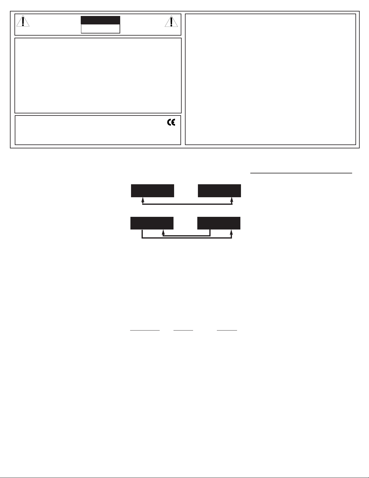
D. FILE DUMP CONNECTIONS
OPEN LOOP MODE
CLOSED LOOP MODE
NOTE:
When sending file dump with an OPEN LOOP MODE, you
should set up the receiving device to RECEIVING MODE
or receiving will be disabled.
1. If MIDI data is not received within 10 minutes, the
channel and program set too MIDI will be cleared.
2. When sending or receiving a file dump, the device ID is
55H. All information is sent or received during a file
dump. You can send SCENE programs to an external
storage or to another unit. You can also receive SCENE
programs from external storage or from another unit.
This unit sends or receives NOTE information , relevant
functions is as follows:
NOTE NUMBER
VELOCITY FUNCTION
22-69 PROGRAM MASTER ON-OFF PROGRAM 1-48
70-93 CHANNEL DIMMER ON-OFF PROGRAM 1-24
94 FULL ON
95 DARK
96 HOLD
97
TURN ON /OFF AUDIO CHASE
98 CHASE SCENES
99 DOUBLE PRESET MODE
100 SINGLE PRESET MODE
101 STEP CHANGE
102 BLACK OUT
RECEIVING INSPECTION—read before getting started
INSPECT YOUR MIXER FOR ANY DAMAGE which may have
occurred during shipping. If any damage is found, please
notify the shipping company and CARVIN immediately.
SAVE THE CARTON & ALL PACKING MATERIALS. In the
event you have to re-ship your unit, always use the original
carton and packing material. This will provide the best possible protection during shipment. CARVIN and the shipping
company are not liable for any damage caused by improper
packing.
SAVE YOUR INVOICE. It will be required for warranty service if needed in the future.
SHIPMENT SHORTAGE. If you find items missing, they
may have been shipped separately. Please allow several days
for the rest of your order to arrive before inquiring.
RECORD THE SERIAL NUMBER on the enclosed warranty
card or below on this manual for your records. Keep your
portion of the card and return the portion with your name
and comments to us.
TRANSMITTER
RECEIVER
MIDI OUT MIDI IN
MIDI OUT MIDI IN
TRANSMITTER
RECEIVER
MIDI OUT MIDI IN
MIDI OUT MIDI IN
CAUTION
RISK OF ELECTRIC SHOCK
DO NOT OPEN
SAFETY INSTRUCTIONS (EUROPEAN)
The conductors in the AC power cord are colored in accordance with the following code.
GREEN & YELLOW—Earth BLUE—Neutral BROWN—Live
U.K. MAIN PLUG WARNING: Amolded main plug that has been cut off from the cord is unsafe. NEVER
UNDER ANYCIRCUMSTANCES SHOULD YOU INSERTA DAMAGED OR CUT MAIN PLUG INTO APOWER SOCKET.
IMPORTANT! FOR YOUR PROTECTION, PLEASE READ THE FOLLOWING:
WATER AND MOISTURE: Appliance should not be used near water (near a bathtub, washbowl, kitchen
sink, laundry tub, in a wet basement, or near a swimming pool, etc). Care should be taken so that
objects do not fall and liquids are not spilled into the enclosure through openings.
POWER SOURCES: The appliance should be connected to a power supply only of the type described
in the operating instructions or as marked on the appliance.
GROUNDING OR POLARIZATION: Precautions should be taken so that the grounding or polarization means of an appliance is not defeated.
POWER CORD PROTECTION: Power supply cords should be routed so that they are not likely to
be walked on or pinched by items placed upon or against them, paying particular attention to cords
at plugs, convenience receptacles, and the point where they exit from the appliance.
SERVICING: The user should not attempt to service the appliance beyond that described in the
operating instructions. All other servicing should be referred to qualified service personnel.
FUSING: If your unit is equipped with a fuse receptacle, replace only with the same type fuse. Refer
to replacement text on the unit for correct fuse type.
REFER SERVICING TO QUALIFIED SERVICE PERSONNEL!
This symbol is intended to alert the user
to the presence of uninsulated “dangerous
voltage” within the product’s enclosure that
may be of sufficient magnitude to consti-
tute a risk of electric shock to persons.
This symbol is intended to alert the
user to the presence of important
operating and maintenance (servicing) instructions in the literature
accompanying the appliance.
LIMITED WARRANTY
Your Carvin product is guaranteed against failure for 1 YEAR unless otherwise stated. Carvin
will service and supply all parts at no charge to the customer providing the unit is under warranty.
Shipping costs are the responsibility of the customer. CARVIN DOES NOT PAY FOR PARTS OR
SERVICING OTHER THAN OUR OWN. A COPY OF THE ORIGINAL INVOICE IS REQUIRED TO
VERIFY YOUR WARRANTY. Carvin assumes no responsibility for horn drivers or speakers damaged by this unit. This warranty does not cover, and no liability is assumed, for damage due to:
natural disasters, accidents, abuse, loss of parts, lack of reasonable care, incorrect use, or failure
to follow instructions. This warranty is in lieu of all other warranties, expressed or implied. No
representative or person is authorized to represent or assume for Carvin any liability in connection with the sale or servicing of Carvin products.
CARVIN SHALL NOT BE LIABLE FOR INCIDEN-
TAL OR CONSEQUENTIAL DAMAGES.
When RETURNING merchandise to the factory, you may call for a return authorization number .
Describe in writing each problem. If your unit is out of warranty, you will be charged the current FLAT RATE for parts and labor to bring your unit up to factory specifications.
MAINTAINING YOUR EQUIPMENT
Avoid spilling liquids or allowing any other foreign matter inside the unit. The panel of your
unit can be wiped from time to time with a dry or slightly damp cloth in order to remove
dust and bring back the new look.
As with all pro gear, avoid prolonged use in caustic
environments (salt air). When used in such an environment, be sure the mixer is adequately protected by a cover.
For your records, you may wish to record the following information.
Serial No.________________________________ Invoice Date_______________
Page 3
CARVIN ENGINEERING DATA LC24 24CH LIGHTING CONSOLE OPERATING MANUAL
12340 World Trade Drive, San Diego, CA 92128
800.854.2235 www.carvin.com
the desired chase speed. The SPEED FADER will over ride a Tap Sync setting as soon
as it is moved. The case speed is off when the Speed fader in the minimum position called
Show Mode this can be over written with the Tap Sync button, simply move the speed
fader up and back down to stop again. In this position the Step button can be used to go
trough the programs steps one step at a time.
• The program should now be chasing to the desired speed set in 5.).
D. PLAYING A SCENE PROGRAM WITH AN AUDIO CHASE:
(Running the new recorded program above with an audio input chase or by simple tapping the top panel for the internal microphone.)
• Set the mode to Scenes by pushing the MODE SET button until the LED for the Scenes
mode is lit.
• Turn ONthe Audio chase (if it is off) by pressing the AUDIObutton. The audio LED should
be lit.
• Press the PAGE button until the page LED over the "3" is lit. This means we are selecting scene programs between 25-36.
• Raise the SCENES CHANNEL 28 FADERto max. This selects the scene program to run.
The light intensity of the program is controlled by this fader.
Starting the audio chase with the internal Microphone
The chase can be started by raising the AUDIO FADER to full and tapping the front panel
each time it is tapped the program should move one step. If music is playing loud enough
or other sounds are loud enough they will trigger the program to chase. By lowering the
AUDIO F
ADER the internal microphone will become less sensitive.
Starting the audio chase using the Audio input jack
First, turn down the AUDIO F
ADER. Then plug into the Audio INPUT JACK
a music source
like a tape deck or CD player. With the music playing, bring up the AUDIO F
ADER
. The
audio input can be over driven and not chasing properly. So move the Audio fader up
slowly to find the point where the scene program is chasing the audio evenly. The first
setting should be good for changes of music on the same source, but an adjustment maybe
needed for bigger changes in the music source.
E. EDITING AN EXISTING SCENE PROGRAM :
(Editing the above Scene Program 28)
• Enter Record mode:
See A. above.
• Enter scene program EDIT MODE
• Set the mode to Scenes by pushing the MODE SET button until the LED for the Scenes
mode is lit.
• Press the PAGE button until the page LED over the "3" is lit. This means we are selecting scene programs between 25-36.
• Press and Hold the EDIT button. Then press the SCENES channel 28 FLASH button.
The Scene 28 yellow LED should light. Scene program 28 is ready to edit.
Deleting a step
Using the STEP button, step to the 3rd step. This should light the channel 3’s LED. Now
press the DELETE button the original step 3 has been deleted and the original step 4 has
now shifted down to step 3. The program only has 3 steps now.
Inserting a step
• First, record the steps to be add: raise the CHANNEL 8 FADERand press record the display should read a 01 for one step recorded.
• Now press the step button to step in the program to the place the new step(s) is to be
inserted and press the INSERT button.
Modify a step
• Use the STEP button to step to the desired step in the program to be modified.
• Press and hold either the UP or Down button. While holding, press the FLASH button
to modify the intensity of this step. The display will show the changing intensity level for
this step. The FLASH button can be held down for fast changes or pressed and released
for incremental changes.
Exit Edit Mode
To exit the edit mode press and hold the RECORD button and press the REC EXITbutton.
Now the console is out of Edit mode and still in Record mode. The LED for the Scene will
turn off.
76-LC2400 0402
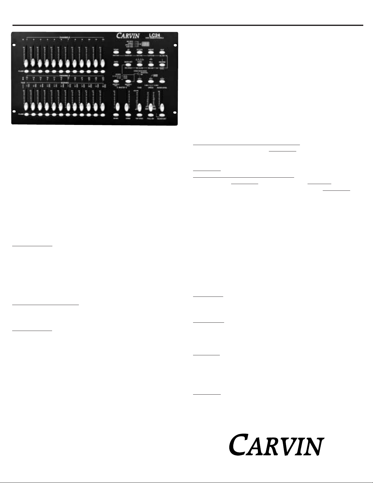
Congratulations on your purchase of the LC24 lighting console. The LC24is a DMX-512
and MIDI compatible microprocessor controlled lighting console. With 48 program locations and 4500 total steps the LC24 provides power control to any lighting system. We
strongly recommend that you read this manual to fully understand the potential of the
LC24 light console.
RECORDING MODE: FEA TURES, HOW TO, AND EXAMPLES
A. TO ENTER RECORDING MODE:
Press and hold the RECORD button, now press–in sequence–the channel FLASHbuttons
1, 5, 6, and 8 while still holding the RECORD button. Release the RECORD button and
the RECORD LIGHT should be lit.
B. RECORDING A SCENE PROGRAM:
(A four step chase program saved into scene program location 28.)
• Enter Record mode: See A. above.
• Creating the four steps.
* Lower all channel FADERS.
* Set the mode LED’s to 1x24 (or 2x12 depending on the light system used)
Programming steps:
• Raise the CHANNEL 1 FADER to max.
• Press the RECORD button once. The display should read 01 for step one.
• Lower the CHANNEL 1 FADER to min.
• Now raise the CHANNEL 2 fader to max
• Press the RECORD button once. The display should read 02 for step two.
• Lower the CHANNEL 2 FADER to min
• Repeat for CHANNEL 3 and CHANNEL 4 FADERS. The display should increment each
time the record button is pressed corresponding to the current step recorded.
Starting over on current program.
• To start over in a program, Press and hold the RECORDbutton and press the REC CLEAR
button. Now the memory is cleared and the next step recorded will be step one of the
new program.
Storing the program
• Press the PAGE button until the page LED over the "3" is lit. This means we are selecting scene programs between 25-36.
• Now press and hold the RECORDbutton and then press SCENE channel 28’s Flash button.
Upon releasing these buttons the program is stored in the scene program location 28.
• Exit record mode
Exit record mode by pressing and holding theRECORD button and then pressing the REC
EXIT button. The record LED should be off now.
C. PLAYING A SCENE PROGRAM WITH A CHASE SPEED:
(Running the new recorded program above with a chase speed.)
• Set the mode to Scenes by pushing the MODE SET button until the LED for the Scenes
mode is lit.
• Turn OFF the Audio chase (if it is on) by pressing the AUDIO button. The audio LED
should be off.
• Press the PAGE button until the page LED over the "3" is lit. This means we are selecting scene programs between 25-36.
• Raise the SCENES CHANNEL 28 fader to max. This selects the scene program to run.
The light intensity, of the program, is controlled by this fader. The scene LED (YELLOW)
should be lit.
• Starting the chase speed
The chase can be started by tapping the TAP SYNCbutton more than twice at the rate of
Page 4

F. DELETING PROGRAMS:
Delete all programs– "clear memory"
Press and hold the RECORD button, now press in sequence
the channel FLASH BUTTONS 1, 3, 2, and 3 while still holding the record button. Release the record button, now all programs are erased.
Delete a single program
• Enter record mode.
• Set the mode to Scenes by pushing the MODE SET button
until the LED for the Scenes mode is lit.
• Press the PAGE button until the page LED until the desire
program range is lit.
• Press and hold the RECORD button. Then press the
FLASH button TWICE of the desired program to be deleted.
FRONT PANEL CONTROLS:
1.) CHANNEL A’S 1-12 LED’S
These LED’s show the channel FADER or FLASHbutton has
been used. The LED’s brightness shows the relative level the
fader is set at. Also, this LED indicates when the channel is
turned on and when a program is running.
2.) CHANNEL A’S 1-12 FADERS
These are the faders used to control the intensity of the light
on that channel. The intensity is in either 0-100% or from
0-255 steps.
3.) CHANNEL 1-12 FLASH BUTTONS
When pressed the channel will output the maximum intensity.
4.)
CHANNEL B’S 1-12 OR A’S 13-24 LED’S
These LED’s show the CHANNEL FADER or FLASH button
has been used. The LED’s brightness shows the relative level
the fader is set at. Also this LED indicates when the channel is turned on and when a program is running. The A and
B number are part of the mode setup.
5.) SCENES 1-12 LED’S
When in the scenes mode (along with the Page button) these
LED’s indicate which Scene or Scenes are running.
6.)
CHANNEL B’S 1-12 AND A’S 13-24 FADERS
These are the faders used to control the intensity of the light
on that channel. The intensity is in either 0-100% or from
0-255 steps. In the Scene Mode these faders control the intensity of the scenes.
7.) CHANNEL B’S 1-12 AND A’S 13-24 FLASH
BUTTONS
When pressed the channel will output the maximum intensity. Also these flash buttons are also used in storing programs in the recording mode.
8.) MASTER A FADER
This FADERwill adjust the over all intensity of the channels
A1-12 in the 2x12 mode, A1-24 (all channels) in the 1x24
mode, and all user controlled channels (A1-12 and BLIND
BUTTON activated A13-24 channels) in the Scenes mode.
9.) BLIND BUTTON
In the Scenes mode this button, when activated, returns control of the SCENE FADERSand FLASH BUTTONSto the user
and leaves the current Scene program running with the intensity left in place. To work the button press and hold the blind
button and then press the desired channels flash button. The
channel is returned to scenes control with the Home button.
10.) MASTER B FADER
This Fader will adjust the over all intensity of the channels
B1-12in the 2x12 mode, used as preset master with MASTER
B FULL button in the 1x24 mode, and controls the over all
intensity of running scenes in the Scene mode.
11.) HOME BUTTON
In the Scenes mode this button, when activated, returns the
SCENE FADERSand FLASH BUTTONSto controlling the Scene
programs. See Blind button.
12.) FADE FADER
This fader adjusts the time a controlled light takes to go from
the off to maximum intensity and the same time is used for
going from maximum to off. This is called the fade time.
13.) TAP SYNC BUTTON
This button is used as an alternate way to define the chase
speed in Scenes mode. When tapping this button the time
between the last two taps is the new chase speed. This button
over rides the Speed fader until the fader is used again.
14.)
SPEED FADER, 5MIN LED, & 10MIN LED
This fader adjusts the chase speed in the Scene mode.
Slowest speed is define in the two LED’s above the fader 5min
or 10min. To change the lowest speed to 5 minutes press
and hold the RECORD button. While holding the RECORD
button down, press channel 5’s FLASH button three times.
After releasing the RECORD button, the 5MIN LED should
light. To change the lowest speed to 10 minutes press and
hold the RECORDbutton. While holding the RECORD button
down, press channel 10’S FLASH button three times. After
releasing the RECORD button, the 10MIN LED should light.
15.) FULL ON button
When pressed all channels with output at full intensity over
ride black out mode while pressed. The button works like a
flash button and only works while pressed.
16.) AUDIO FADER
This fader controls the sensitivity of the internal microphone and audio input jack.
17.) BLACK OUT BUTTON & LED
The BLACK OUTbutton turns off all lights. One press of the
button turns on the BLACK OUT LED and the unit stays on
black out until the button is pressed again. The channel Flash
buttons and the Full On flash button over ride the Black Out
button as long as they are held down.
18.) STEP BUTTON
In the Scenes mode, if the chase speed has not been set (the
chase speed LED is not flashing) then this button can be used
to step a program through one step pre button press. If the
chase LED is showing a chase speed, lower the speed fader
to its bottom "Show Mode" position now the step button can
be used.
19.) AUDIO BUTTON & AUDIO LED
In Scene mode, the AUDIO button, when pressed, lights the
AUDIO LEDand puts the console into AUDIO CHASE MODE.
If there is nothing inserted into the AUDIO IN RCA JACK the
audio input is the internal microphone. If the RCA JACK is
used the microphone is disabled. The audio chase mode is
exited by pressing the AUDIO button again.
20.) HOLD BUTTON & LED
When the HOLDbutton is pressed and held, the console current output for all channels is held. This allows all or any
fader change with out showing on the output until this
button is released. If a Scene is chasing the output at the
moment the HOLD button is pressed is held. The chase will
continue upon the release of the HOLD button. The channel
FLASH, The FULL ON, BLACK OUT, and DARK Buttons will
work during the hold button feature.
21.) MASTER A FULL, MASTER B FULL BUTTONS,
& SCENE CHASE MODE LED’S
In All three modes the MASTER A FULL button works like a
flash button for the MASTER A FADER. MASTER B FULL
button selects the Scene Chase Mode in the Scenes mode,
it works as a MASTER B FADER FLASH button in the 2x12
mode, and works as a single scene store button, with
MASTER B fader, in the 1x24 mode. The single scene store
feature stores a snap shot of the channel faders at the time
the MASTER B FULL button is pressed, this can be cleared
by lowering all the channel faders to 0 and pressing the
MASTER B FULL button. In Scenes mode, the Sequential
scene chase mode runs multiple scene programs sequentially, and the Mix mode runs multiple scene programs
simultaneously.
22.) KILL / REC EXIT BUTTON & YELLOW ADD LED
Pressing the KILLbutton turns on the ADD LED and puts the
console in kill mode. Kill mode works when any or multiple
channel Flash buttons are press. The pressed flash buttons
light their channels and turn off all other channels for as long
as one channel flash button is still held down. In record mode
by pressing the RECORD/SHIFT button holding it and then
the KILL / REC EXIT button upon the release of both buttons
Record mode will be exited. See the Record Mode section.
23.) RECORD / SHIFT BUTTON & RED LED
The RECORD button is used to enter the record mode by
pressing and holding the record button, then sequentially
pressing FLASH 1, FLASH 5, FLASH 6,and FLASH 8. When
the RECORDbutton is released the red RECORD LED will light
and the console is in record mode. In record mode the
RECORD button is used to record each step of a program.
The SHIFT function activates the alternate functions on the
under side of the %or 0-255button and the REC CLEAR and
REC EXIT buttons, that only work in Record mode. To activate an alternate button function press and hold the
RECORD/SHIFT button and then press the desired alternate
button. When both buttons are released the alternate function will be implemented.
24.) PAGE BUTTON / REC CLEAR BUTTON &
GREEN 1-4 LED’S
In Scene mode the PAGE button selects which scene programs the channel B 1-2 fader control. The 4 pages times
the 12 channel B faders equals the 48 possible scene programs. In the Record mode the PAGE button along with a
channel B FLASH button select where a program is stored.
Also in Record mode the alternate (see Record/Shift button)
REC CLEAR function clears the current program.
25.)
MODE SET / REC SPEED BUTTON & 3 MODE LED’S
The Mode Set button toggles through the three operating
modes and LED’s. In Scene mode the alternate Rec Speed
function assigns a chase speed to any scene program. First,
select the desired chase speed, via the speed fader or the tap
sync button, then press and hold the REC SPEEDbutton and
the desired Scene’s FLASH button. When both buttons are
LC24 24CH LIGHTING CONSOLE
Page 5

released the scene program is locked so that chase speed
and other programs can be set to new chase speeds. To return
a Scene program’s chase speed control to the speed fader,
place the Speed fader in the bottom SHOW MODE position.
Press and hold the REC SPEEDbutton along with the Scene
programs FLASH button upon release of both buttons the
control is restored.
26.) DARK BUTTON
The DARK button is like a momentary version of the
BLACKOUTbutton. Except the DARK button cannot be over
ridden by any other button while still pressed.
27.) ALL REV BUTTON / EDIT
The ALL REVbutton works in the Scenes mode. It reverses
the direction of the chase for all scene programs running
whether or not a chase speed was set using the Rec Speed
button. In record Mode and in Scene mode the alternate Edit
function pressed in conjunction with a scene flash button
puts the console in the edit mode of that scene program.
See Record Mode.
28.) % OR 0-255 / INSERT BUTTON
The % OR 0-255button is used to change the dimmer readout on the LED display from 0-100% to 0-255 steps. This
is only a display reading preference. The function toggles
every time the RECORD and "% OR 0-255" buttons are
press and the same time. The alternate Insert function works
in the record Edit mode. It is used to insert a new step into
an existing program.
29.) REV ONE / DELETE BUTTON
The REV ONE button reverses the scene program who’s
FLASH button is pressed at the same time. The alternate
Delete function works in the record Edit mode. It is used to
delete a new step into an existing program.
30.) CHASE REV / UP BUTTON
The CHASE REV button works in the Scene mode and
reverses the chase direction of the any programs running
to a chase speed it will not rev scene programs that have
their chase speed set by using the REC SPEED button. The
UP function works in the record Edit mode. It is used to
change the dimmer intensity in an existing program. In the
record Edit mode, a steps dimmer intensity value is changed
by pressing and holding the UP button, then as the FLASH
button under the channel to be modified is pressed the intensity is increased. The alternate Chase Rev function works
in the Scene mode and reverses the chase direction of the
any programs running to a chase speed it will not rev scene
programs that have their chase speed set by using the REC
SPEED button.
31.) BEAT REV / DOWN BUTTON
The BEAT REVbutton works in the Scene mode with scene
programs that have their chase speed set by the REC SPEED
button and are now running with other programs with audio
chase activated. The Set Speed chase programs will reverse
on the next beat (may have to hold the button for two beats)
after the button is released.
The alternate Down function works in the record Edit mode.
It is used to change the dimmer intensity value of a step in
an existing program. In the record Edit mode, a step’s dimmer
intensity value is change by pressing and holding the Down
button, then as the Flash button under the channel to be modified is pressed the intensity is decreased.
REAR PANEL CONTROLS:
32.) POWER INPUT JACK
Use supplied AC wall adapter.
33.) MIDI THRU
Use for serial connections of more MIDI devices connected
after the LC24. Has same MIDI information as going into
the MIDI in jack.
34.) MIDI OUT
Use for send out MIDI information from the LC24.
35.) MIDI IN
Used for receiving MIDI information into the LC24.
36.) DMX OUTPUT
Used for send information to Dimmer packs etc.. in the DMX512 format.
37.) DMX POLARITY SELECT
Reverses the polarity of the balanced DMX lines. Used if
Dimmer packs etc.. used with the LC24 only conform to a
certain polarity. See Dimmer pack and other peripherals for
correct polarity. The polarity will not damage peripherals,
but they may not function properly with an incorrect setting.
38.) THE AUDIO INPUT
The audio input jack when used turns off the internal microphone. I can handle from 100mV to 1V pp and is controlled
by the audio fader. This jack is used to control the chase rate
of a scene program with an audio source.
39.) REMOTE CONTROL INPUT:
The stereo (TRS) 1/4" jack is used to remotely control the
Full On and Black Out features of the console. The tip is the
Full On control. It works in either momentary hold or push
on push off. The Ring is the
Black Out control and works as
push on / push off. This is the
same are these switches work
on the front console.
1
2
3
4
5
6
7
8
9
10
11
12
13 14 15
16
17
18
20
19
21
22
23
24
25
26
27
28
29
30
31
LC24 REAR CONNECTIONS
32
33
34
35
36
37
38
39
Page 6

Page 7

 Loading...