

Page 1
IN
1
2
3
F
INPUT A
LEVEL
RIGHT A
OUTPUT
AMPS
IN
1
2
3
F
LEFT A
AUX IN
IN
1
2
3
F
RIGHT B
IN
1
2
3
F
LEFT B
INPUT B
LEVEL
PHONES
LEVEL
MONO
OUT
INPUT
INPUT
INPUT
INPUT
CH 2
CH 3
CH 4
PHONES
OUTPUT 1
R
L
R
L
MONO
AUX IN
R
L
R
L
CHANNEL 1
A RIGHT
A LEFT
B RIGHT
B LEFT
SIG
PK
REAR AUX
OUTPUT 1
RECEIVING INSPECTION
INSPECT YOUR H400 FOR DAMAGE which may have occurred during shipping. If
any damage is found, please notify the shipping company and CARVIN.
SAVE THE CARTON & ALL PACKING MATERIALS. In the event you have to re-ship
your unit, always use the original carton and packing material. This will provide the
best possible protection during shipment. CARVIN and the shipping company are not
liable for damage caused by improper packing.
SAVE YOUR INVOICE. It will be required for warranty service if needed in the future.
SHIPMENT SHORTAGE. If you find items missing, they may have been shipped
separately. Please allow several days for the rest of your order to arrive before inquiring.
RECORD THE SERIAL NUMBER on the enclosed warranty card for your records.
Keep your portion of the card and return the portion with your name and
comments to us.
USA customers register online at: www.carvin.com/registration
All other countries register online at: www.carvinworld.com/registration
CARVIN ENGINEERING DATA H400 FOUR CHANNEL HEADPHONE AMP
34
H400
FOUR CHANNEL
.
.
HEADPHONE AMP
2
PHONESAUX IN
INPUT A
010
5
1
010
5
010
5
INPUT B INPUT A
010
5
010
5
010
5
INPUT A
010
5
010
5
010
5
INPUT A
010
5
010
5
010
5
INPUT B INPUT B
LEVEL
PHONES
INPUT B
OUT
AUX IN
MONO
PHONESAUX IN PHONESAUX IN PHONESAUX IN
PKSIG
AUX IN
MONO
OUTPUT
LEVEL
PHONES
OUT
AUX IN
MONO
SIG
AUX IN
MONO
OUT
LEVEL
PHONES
OUT
AUX IN
MONO
PKSIG
AUX IN
MONO
OUTPUT
LEVEL
PHONES
OUT
AUX IN
MONO
PKSIG
AUX IN
MONO
OUTPUT
POWER
76-02424B 012304
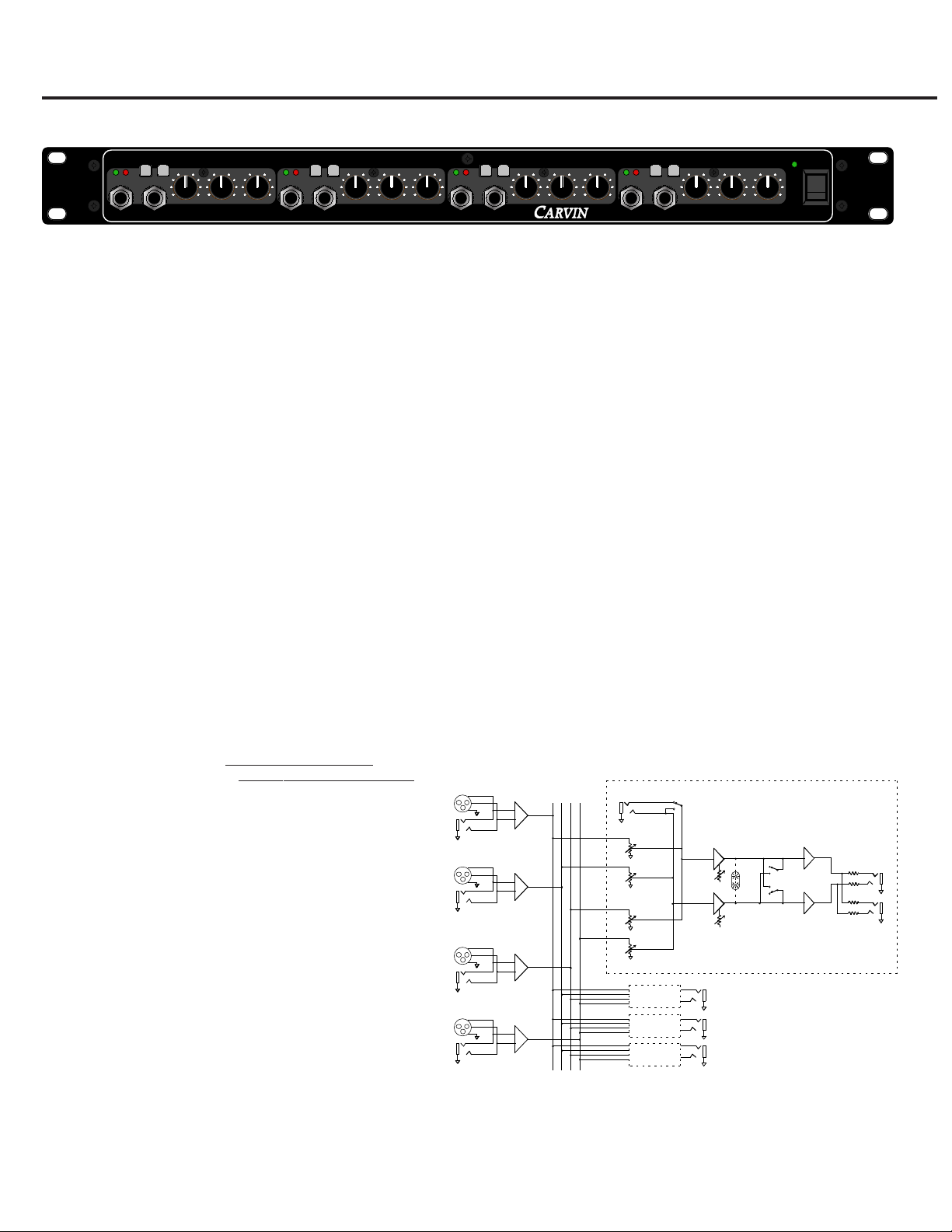
Congratulations on your purchase of the CARVIN H400 Four
Channel Headphone Amp. Your unit has been engineered and
made in the U.S.A. using only high quality electronic components
and uncompromising workmanship.
The H400 will drive a total of eight pairs of headphones to their
maximum output with excellent clarity. The H400 features four
independent output channels each with it’s own mix of 3 stereo
sources: INPUT A, INPUT B and the AUX IN for that channel.
When using the unit in MONO, a total of 4 main inputs plus 2 aux
inputs for each channel are available. The signal routing flexibility
of the H400 makes it useful as a distribution amp for installation
applications.
Use caution with the H400. It is capable of high levels which may
cause hearing damage.
c
FREQUENCY RESPONSE: 5Hz TO 40kHz, -0.5dB (INPUT A or B)
20Hz TO 40kHz, -0.5dB (AUX IN)
OUTPUT POWER: 2W @ 40Ω
800 mW @ 150Ω
240mW @ 600Ω
THD+N: 20Hz TO 20kHz, 0.01% @ 90% POWER
INPUT IMPEDANCE: 20KΩ BAL., 10KΩ UNBAL.
OUTPUT IMPEDANCE: 11Ω or greater
INPUT to OUTPUT GAIN: 20dB
S/N RATIO: >100dB
STEREO INPUTS A & B: XLR BALANCED,
1/4” BALANCED or UNBALANCED
with GROUND LIFT
FRONT AUX INPUTS: 1/4” STEREO,
MONO switch
OUTPUTS: 1/4” STEREO front and rear, MONO switch,
SIGNAL and PEAK indicators
POWER REQUIREMENTS: 4VA, 90-255VAC, 50/60Hz SWITCHING SUPPLY
FUSE: INTERNAL 1.5A FAST BLOW
DIMENSIONS: 1.75”H x 19”W x 5”D
SHIPPING WEIGHT: 7 LBS
H400 SPECIFICATIONS
BLOCK DIAGRAM
Page 2
REAR PANEL
1-800-854-2235
www.carvin.com
AUS
H400
HEADPHONE AMP
SERIAL NUMBER
90-250 VAC
INTERNAL FUSE
10 VA 50-60Hz
CH 1
CH 2
CH 3
CH 4
AUX OUTPUTS
LEFT
B
RIGHT
B
LEFT
A
RIGHT
A
GND
LIFT
GND
LIFT
MADE IN THE
34
H400
FOUR CHANNEL
.
.
HEADPHONE AMP
INPUT A
010
5
010
5
010
5
INPUT A
010
5
010
5
010
5
INPUT B
LEVEL
PHONES
INPUT B
OUT
AUX IN
MONO
PKSIG
AUX IN
MONO
OUTPUT
LEVEL
PHONES
OUT
AUX IN
MONO
NO
POWER
12
14
14
13
13
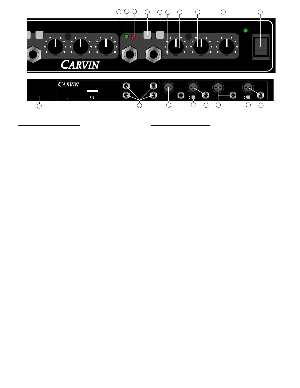
FRONT PANEL FEATURES:
1. AUX INPUT JACK
Receives stereo or mono inputs from sources to be heard only at
the related PHONES output. Adjust the input level with the LEVEL
PHONES control then adjust INPUTs A&B accordingly.
2. PHONES OUTPUT JACK
Plug headphones into this jack. Start with the LEVEL PHONES at a
low setting to avoid damage to your hearing or to headphones.
3. PHONES LEVEL CONTROL (AUX IN)
Adjusts the output volume heard at the PHONES jack and the input
level from the AUX IN jack.
4. INPUT A CONTROL
Adjusts the volume of INPUT A going to the LEVEL PHONES heard
at the PHONES jack for the related channel 1-4.
5. INPUT B CONTROL
Adjusts the volume of INPUT B going to the LEVEL PHONES heard
at the PHONES jack for the related channel 1-4.
6. SIG LED
Shows when a signal is present at the PHONES jack output.
7. PK LED
Shows when the output signal of the channel is being overdriven.
Reduce the PHONES LEVEL control if the LED lights.
8. MONO AUX IN SWITCH
Pressing the MONO AUX IN switch IN causes the AUX IN jack to
receive signal from the TIP conductor only, sending the same
signal to Left and Right.
9. MONO OUT SWITCH
Pressing the MONO OUT switch IN sends the same MONO signal
to both the Left and Right sides of the PHONES jack.
10. POWER
Push this switch to the UP position to apply power to the unit.
The POWER LED will display to show that the H400 is on.
REAR PANEL FEATURES:
11. LINE CORD:
The exclusive built-in auto switching power supply allows you to
connect any voltage from 90 to 255v 50-60Hz. Use a 3-conductor
line cord for maximum safety. If the H400 is to be plugged into a
2-prong outlet, use a quality 3-to-2 prong grounded adapter. Do
not defeat the grounding pin of your AC line cord.
12. AUX PHONES OUTPUTS 1-4:
These jacks are connected in parallel with the corresponding
PHONES jacks on the front panel. When using both the front and
rear outputs of a channel, use headphones of similar
impedances. Using headphones of different impedances on the
same channel may result in radically different volume levels.
13. XLR AND 1/4” INPUT JACKS A&B:
Connect your inputs here. Adjust the levels at each output
channel with the INPUT A and INPUT B controls. If MONO
sources are being monitored, use the MONO OUT switches on
the front panel. A total of four MONO inputs can be used in this
case.
14. GROUND LIFT SWITCH:
This switch lifts the grounds on the inputs and outputs when
pressed IN. This is useful for eliminating ground loops.
11
8
7
6
FRONT PANEL
9
13
13
1
3
2
4 5
10
Page 3

H400 SETUPS:
The H400 can be used in various configurations.
For a basic headphone monitor connection, the H400 LEFT A and
RIGHT A inputs are connected to the MAIN outputs of a mixer.
Headphones are plugged into the front PHONES jacks. Start with
all controls at minimum. With music playing from the mixer, turn
the INPUT A control to about “5” then gradually raise the PHONES
LEVEL control to a comfortable listening level.
Fig. 1 shows a more complex monitoring setup. Each headphone
channel gets a separate mix of INPUT A and INPUT B. The
channel’s AUX IN jack allows monitoring of a THIRD source heard
only at that channel.
The H400 A and B inputs are connected to separate AUX SENDs
of a mixer. The H400 Channel 1 AUX IN jack is connected to a
mixer channel’s DIRECT OUT. Set the MONO AUX IN switch to the
“IN” position.
While playing the instrument on the mixer channel selected,
adjust the H400 LEVEL PHONES control to a listenable level.
Adjust the INPUT A and INPUT B controls to blend in the desired
mix of signals from the mixer. For example, assign drums and
bass to the mixer aux send going to INPUT A and assign the vocals
and guitar to the mixer aux send going to INPUT B. The guitarist
(mixer channel “8”) may want to hear more guitar so connect the
DIRECT OUT from mixer channel “8” to the AUX IN jack of
headphone channel ”1”. The bassist may want to hear more kick
drum (mixer channel “7”) so connect the DIRECT OUT from mixer
channel “7”(kick) to the AUX IN jack of headphone channel ”2”.
FIG. 1
78
DIRECT
OUT
MIC
LINE
IN
TAPE
IN
DIRECT
OUT
MIC
LINE
IN
TAPE
IN
AUX SENDS
6
54321
7/8
1
LEFT
AUX
SEND
L-R
5
L
R
IN
OUT
PFL
6 78
1234
AUX
RETURN
POWER
GROUPS
2345678
LR
12LR3
LR4LR
0
10
5
0
10
5
0
10
5
0
10
5
0
10
5
0
10
5
0
1010
5
PFL PFL PFL PFL PFL
INSERTS
1 2345678
L
R
FLIP FLIP FLIP FLIP
RIGHT
TO GRP 1
XLR
TO GRP 2
XLR
TO GRP 3
XLR
TO GRP 4
XLR
CONTROL
L-R
STUDIO
L-R
PHONES
PHONES
TAPE
2
PHONESAUX IN
INPUT A
010
5
1
010
5
010
5
INPUT B INPUT A
010
5
010
5
010
5
INPUT B
PHONESAUX IN
LEVEL
PHONES
OUT
AUX IN
MONO
PKSIG
AUX IN
MONO
OUTPUT
LEVEL
PHONES
OUT
AUX IN
MONO
PKSIG
AUX IN
MONO
OUTPUT
LEFT
B
RIGHT
B
LEFT
A
RIGHT
A
GND
LIFT
GND
LIFT
H400 FRONT PANEL
H400 REAR PANEL
SL24
MIXER
CHANNEL
DIRECT OUTS
SL24
MIXER
AUX SENDS
PHONES PHONES
Page 4

CAUTION
RISK OF ELECTRIC SHOCK
DO NOT OPEN
SAFETY INSTRUCTIONS (EUROPEAN)
The conductors in the AC power cord are colored in accordance with the following code.
GREEN & YELLOW—Earth BLUE—Neutral BROWN—Live
U.K. MAIN PLUG WARNING: A molded main plug that has been cut off from the cord is unsafe. NEVER
UNDER ANY CIRCUMSTANCES SHOULD YOU INSERT A DAMAGED OR CUT MAIN PLUG INTO A POWER SOCKET.
IMPORTANT! FOR YOUR PROTECTION, PLEASE READ THE FOLLOWING:
WATER AND MOISTURE: Appliance should not be used near water (near a bathtub, washbowl,
kitchen sink, laundry tub, in a wet basement, or near a swimming pool, etc). Care should be taken
so that objects do not fall and liquids are not spilled into the enclosure through openings.
POWER SOURCES: The appliance should be connected to a power supply only of the type
described in the operating instructions or as marked on the appliance.
GROUNDING OR POLARIZATION: Precautions should be taken so that the grounding or
polarization means of an appliance is not defeated.
POWER CORD PROTECTION: Power supply cords should be routed so that they are not likely to
be walked on or pinched by items placed upon or against them, paying particular attention to
cords at plugs, convenience receptacles, and the point where they exit from the appliance.
SERVICING: The user should not attempt to service the appliance beyond that described in the
operating instructions. All other servicing should be referred to qualified service personnel.
FUSING: If your unit is equipped with a fuse receptacle, replace only with the same type fuse.
Refer to replacement text on the unit for correct fuse type.
REFER SERVICING TO QUALIFIED SERVICE PERSONNEL!
This symbol is intended to alert the user to
the presence of uninsulated “dangerous
voltage” within the product’s enclosure that
may be of sufficient magnitude to
constitute a risk of electric shock to persons.
This symbol is intended to alert the
user to the presence of important
operating and maintenance
(servicing) instructions in the
literature accompanying the appliance.
LIMITED WARRANTY
Your Carvin product is guaranteed against failure for 1 YEAR unless otherwise stated. Carvin
will service and supply all parts at no charge to the customer providing the unit is under
warranty. Shipping costs are the responsibility of the customer. CARVIN DOES NOT PAY FOR
PARTS OR SERVICING OTHER THAN OUR OWN. A COPY OF THE ORIGINAL INVOICE IS
REQUIRED TO VERIFY YOUR WARRANTY. Carvin assumes no responsibility for horn drivers or
speakers damaged by this unit. This warranty does not cover, and no liability is assumed, for
damage due to: natural disasters, accidents, abuse, loss of parts, lack of reasonable care,
incorrect use, or failure to follow instructions. This warranty is in lieu of all other warranties,
expressed or implied. No representative or person is authorized to represent or assume for
Carvin any liability in connection with the sale or servicing of Carvin products.
CARVIN SHALL
NOT BE LIABLE FOR INCIDENTAL OR CONSEQUENTIAL DAMAGES.
When RETURNING merchandise to the factory, you may call for a return authorization
number. Describe in writing each problem. If your unit is out of warranty, you will be charged
the current FLAT RATE for parts and labor to bring your unit up to factory specifications.
MAINTAINING YOUR EQUIPMENT
Avoid spilling liquids or allowing any other foreign matter inside the unit. The panel of
your unit can be wiped from time to time with a dry or slightly damp cloth in order to
remove dust and bring back the new look.
As with all pro gear, avoid prolonged use in
caustic environments (salt air). When used in such an environment, be sure the mixer is
adequately protected by a cover.
 Loading...