

Page 1
GH Pump
Part Number: _______________________________________
Serial Numbers: _____________________________________
These operating instructions contain fundamental information and precautionary notes. Please read the manual
thoroughly prior to installation of unit, electrical connection and commissioning. It is imperative to comply with all other
operating instructions referring to components of individual units.
I-120
120 – 16.02.EN
SAFETY, INSTALLATION, OPERATION AND
MAINTENANCE INSTRUCTIONS
This manual shall always be kept close to the unit’s location of operation or directly on the pump set.
Page 2

I-120
EC Declaration of Conformity
Kurt Doren
Quality/ ISO Manager
www.carverpump.com
Phone: 1-563-263-3410
Email: [email protected]
GH Pump 120 – 16.02.EN
MANUFACTURER: CARVER PUMP COMPANY
2415 PARK AVE.
MUSCATINE, IOWA, USA 52761
PRODUCT DESCRIPTION: 120 GH Pumps
PART NUMBER:
SERIAL NUMBER:
DATE MANUFACTURED:
APPLICABLE EUROPEAN DIRECTIVES:
Machinery: The designated product complies with the following basic requirements of Directive 2006/42/EC:
Appendix I, section 1.1.2, 1.1.3., 1.1.5., 1.3.1., 1.3.2., 1.3.3., 1.3.4., 1.3.7., 1.3.8., 1.4.1., 1.4.2.1., 1.5.1., 1.5.8.,
1.5.9., 1.5.13., 1.6.1., 1.6.4., 1.6.5., 1.7.
APPLICABLE HARMONIZED STANDARDS:
Machinery: EN ISO 12100:2010 EN ISO 13732-1:2008
EN 626-1:2008 EN ISO 13857:2008
Declaration of Incorporation of Partly Completed Machinery (valid for 120 pumps supplied without a motor)
The product described in this Declaration of Conformity complies with the Applicable European Directives, EHSRs and relevant
sections of the Applicable International Standards "as a Component". The incorporation of this pump with Electric Motors that
are marked to confirm that they comply with the Low Voltage Directive 2006/95/EC and all the necessary guards, must be
declared in conformity by the assembler.
Declaration of Conformity of Completed Machinery (valid for 120 pumps supplied complete with a motor)
The product described in this Declaration of Conformity complies with the Applicable European Directives, EHSRs and relevant
sections of the Applicable International Standards. Motors for CE marked pumps will have motors that are marked to confirm that
they comply with the Low Voltage Directive 2006/95/EC.
The special technical documentation has been complied according to Annex VII Part B of Directive 2006/42/EC, and will be made
available in electronic form to the authorities of the individual states upon justified request.
NOTE: The 120 pumps are NOT supplied or declared to ATEX Directive 94/9/EC.
Person authorized to compile the technical documentation:
Kurt Doren, Quality/ISO Manager, Carver Pump Company, 2415 Park Ave, Muscatine Iowa, USA 52761
Authorized Signature: Date:
Important safety information is contained in the installation, operation and service manuals; read and understand this
information prior to installing or using this equipment
This Document applies only to the equipment described above and is invalid if not reproduced in its entirety.
Page 3
I-120
Installation Date
Location
Application
GH Pump 120 – 16.02.EN
SERVICE RECORD PAGE
Service No. ______________________ Model _________________________ Size and Type _______________
Customer Order No. ____________________________ Date Installed __________________________________
PUMP RATING
Capacity _____________________________________ Total Head ____________________________________
Suction Pressure ______________________________ Speed (RPM) __________________________________
Liquid pumped ________________________________ Temperature ___________________________________
Specific Gravity _______________________________ Viscosity ______________________________________
Service ______________________________________
PUMP MATERIALS
Casing _________________________ Impeller _______________________ Shaft _______________________
Gaskets _____________________________________ Bearing Frame _________________________________
Mechanical Seal/Packing ________________________
MOTOR DATA
Motor __________________________ Make _________________________ Serial No. ___________________
Type ___________________________ Frame ________________________ AC or DC ___________________
HP _____________________________ RPM _________________________ Volts _______________________
Phase __________________________ Cycles ________________________
Page 4

I-120
INSPECTION DATE
REPAIR TIME
REPAIRS
COST REMARKS
GH Pump 120 – 16.02.EN
NOTES ON INSPECTION AND REPAIRS
Page 5

I-120
GH Pump 120 – 16.02.EN
INSTALLATION, OPERATION AND
MAINTENANCE INSTRUCTIONS
TABLE OF CONTENTS
SECTION/PARAGRAPH PAGE
SECTION/PARAGRAPH PAGE
I. GENERAL DESCRIPTION ............................... 1
A. General Information ................................... 1
B. Machinery Directive 2006/42/EC ............... 1
C. Disclaimer .................................................. 1
D. Personnel Qualification and Training ......... 1
E. Pump Identification..................................... 2
F. Parts Inventory Guide ................................ 2
G. Parts Ordering ............................................ 2
H. Unauthorized Modification and
Manufacture of Spare Parts ..................... 2
I. Unauthorized Modes of Operation ............. 2
II. SAFETY ............................................................ 2
A. Safety Precautions ..................................... 2
B. Summary of Safety Marking ....................... 2
C. Scope of Compliance ................................. 3
D. Safety Awareness ...................................... 3
E. Safety Instructions for the Operator/User .. 3
F. Safety Instructions for Maintenance
Inspection and Installation Work ............ 3
G. General Safety Instructions ........................ 3
H. Non-Compliance with Safety Instructions .. 4
III. EQUIPMENT DESCRIPTION ........................... 4
IV. EFFECTS OF FLUIDS ..................................... 5
A. Net Positive Suction Head (NPSH) ............ 5
B. Changing Pump Speed .............................. 5
C. Effects of Viscosity ..................................... 5
D. Effects of Specific Gravity .......................... 5
V. TECHNICAL DATA ........................................... 5
VI. INSPECTION AND STORAGE ........................ 8
A. Inspection ................................................... 8
B. Packing for Return ..................................... 8
C. Storage of Pump ........................................ 8
VII. INSTALLATION ................................................ 9
A. Location ...................................................... 9
B. Handling ..................................................... 9
C. Foundation ................................................. 9
D. Leveling of Unit .......................................... 10
E. Grouting ..................................................... 10
F. Coupling Alignment .................................... 11
G. Pre-Installation Procedures ....................... 12
H. Piping ......................................................... 12
I. Auxiliary Piping Connections
and Gauges ........................................... 12
J. Motor .......................................................... 12
K. Direction of Rotation .................................. 12
VIII. OPERATION .................................................... 13
A. Pre-Start Cautions ..................................... 13
B. Priming ....................................................... 13
C. Starting the Pump ...................................... 13
D. Operating Checks ...................................... 14
E. Stopping the Pump .................................... 14
F. Indefinite Shutdown ................................... 14
IX. TROUBLESHOOTING OPERATING
PROBLEMS ...................................................... 14
X. MAINTENANCE ............................................... 17
A. Lubrication of Pump Bearings .................... 17
B. Lubrication of Motor Bearings .................... 18
C. Torque Values ............................................ 18
XI. SERVICE AND REPAIR ................................... 18
A. Preparations for Disassembly of Pump ..... 18
B. Disassembly of Pump ................................ 19
C. Parts Inspection ......................................... 21
D. Reassembly of Pump ................................. 23
E. Replacement of Packing ............................ 25
F. Replacement of Mechanical Seal .............. 26
G. Replacement of Optional Wear Ring on
Pump Equipped with Enclosed Impeller .... 27
H. Motor .......................................................... 27
I. Check Valve ............................................... 27
XII. PARTS LISTS AND DRAWINGS ..................... 27
Page 6

I-120
GH Pump 120 – 16.02.EN
TABLE OF CONTENTS - Continued
LIST OF TABLES
NUMBER TITLE PAGE
1. Maximum Discharge Pressure on
Discharge Case ......................................... 4
2. Key Component Materials ........................... 7
3. Key Mechanical Data ................................... 7
4. Pumping Unit Troubleshooting .................. 15
5. Recommended Torque Values .................. 18
6. Recommended Equipment ........................ 18
7. Parts List .................................................... 26
8. Recommended Spare Parts ...................... 27
LIST OF ILLUSTRATIONS
NUMBER TITLE PAGE
1. Stuffing Box Dimensions.............................. 6
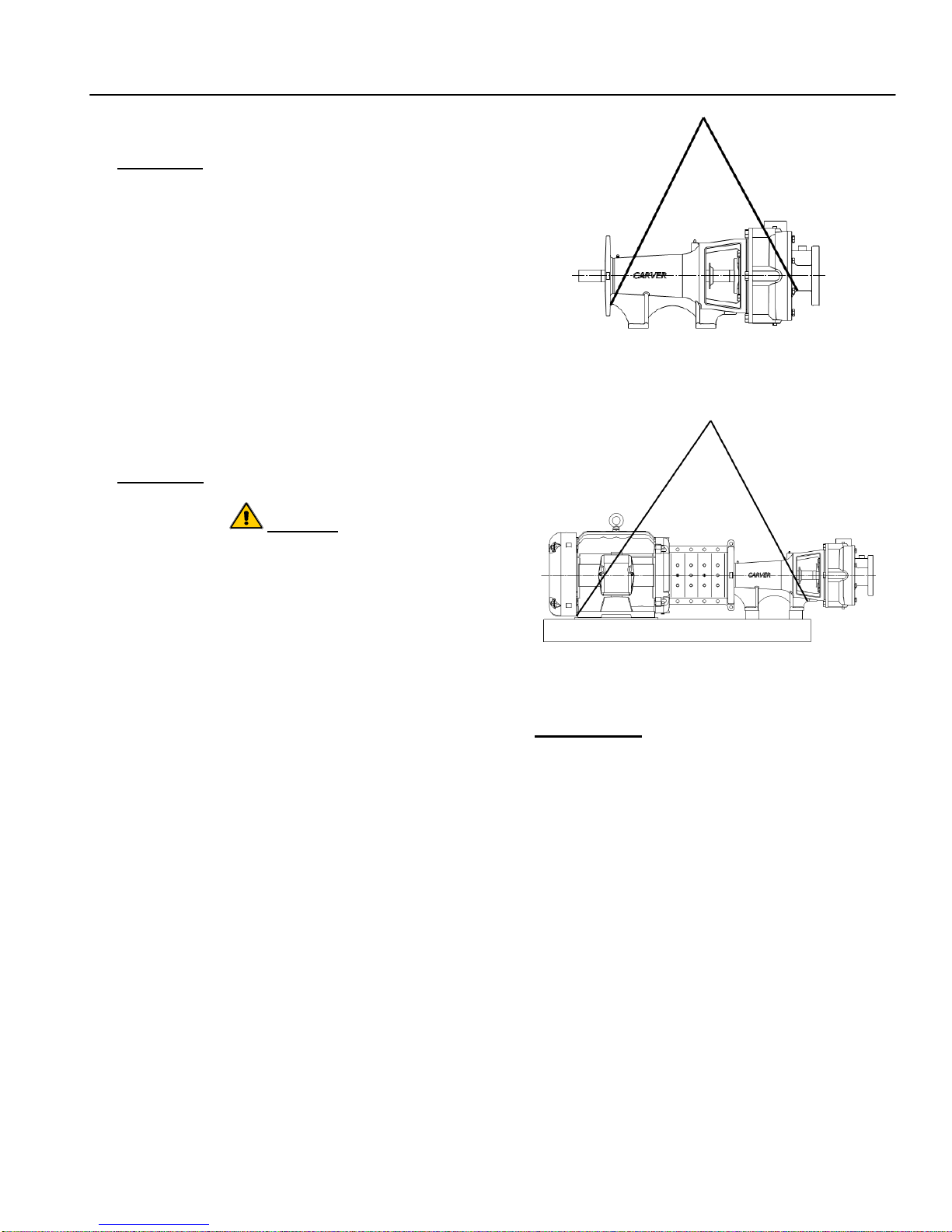
2. Transport of the Bare Pump ........................ 9
3. Transport of Close-Coupled Pump .............. 9
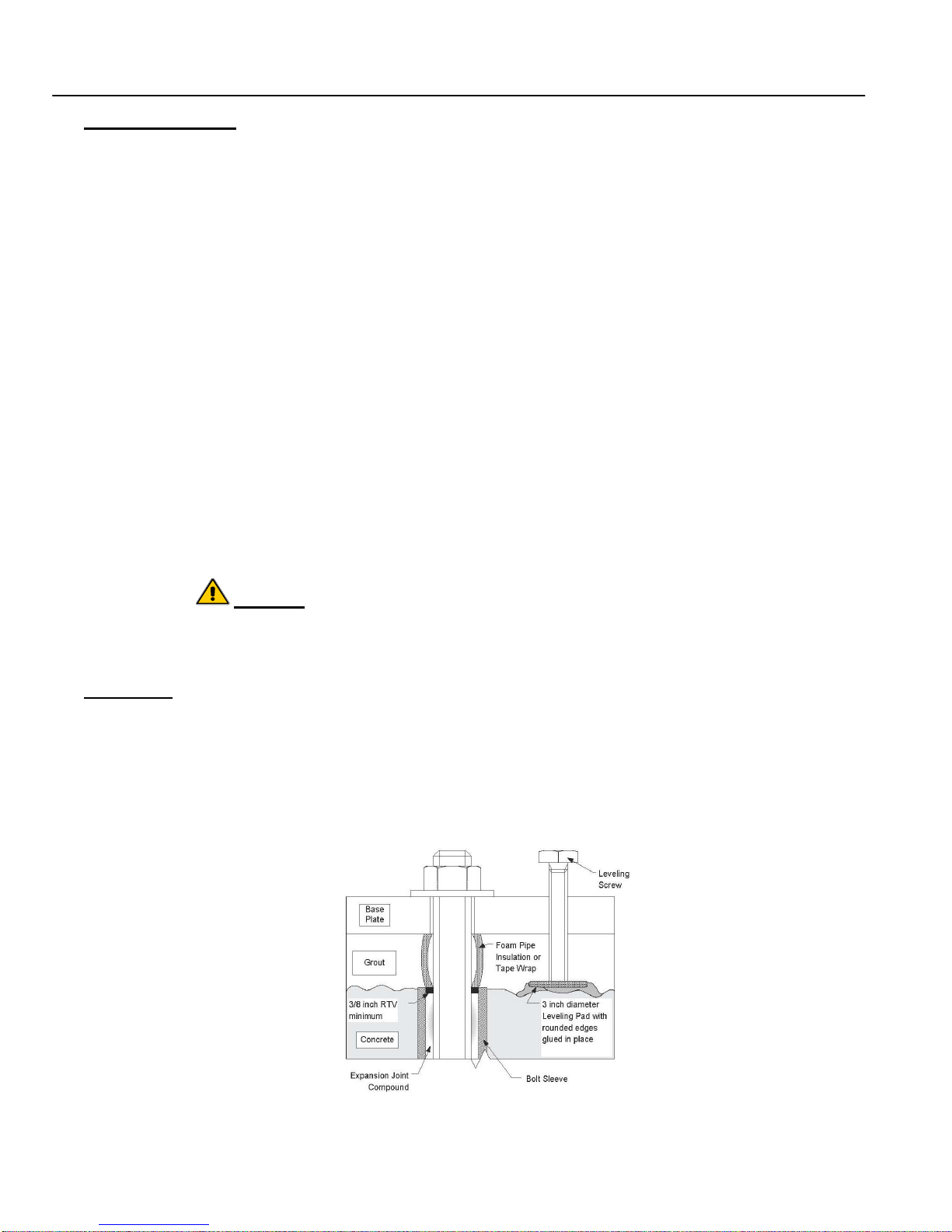
4. Grout and Foundation Bolting ...................... 10
5. Coupling Alignment ...................................... 11
6. Removing Packing with Hook ...................... 24
7. Packing Alignment ....................................... 24
8. Mechanical Seal .......................................... 25
9. Exploded View – Frame Mounted
(Shown with Mechanical Seal) .................. 29
10. Exploded View - Close-Coupled
(Shown with Packing) ................................ 30
Page 7

I-120
GH Pump 120 – 16.02.EN
I. GENERAL DESCRIPTION AND
SAFETY PRECAUTIONS.
A. GENERAL INFORMATION. Carver Pump
Company products are carefully engineered and
manufactured and, if properly installed, maintained, and
operated, should provide maintenance-free operation
and a long service life.
CAUTION
B. MACHINERY DIRECTIVE 2006/42/EC. This
product is designed to Conform with Machinery Directive
2006/42/EC, Safety of Machinery EN ISO 12100:2010,
EN ISO 13732-1:2008, EN 626-1:2008, EN ISO
13857:2008, and the EHSRs.
Complete Machinery for use in EU and EAA will have
CE mark and Declaration of Conformity. Motors for CE
marked pumps will have motors that are marked to
confirm that they comply with the Low Voltage Directive
2006/95/EC.
These instructions must always be kept close
to the product's operating location or directly
with the product.
This manual is designed to provide sufficient material to
properly maintain the total pumping unit. The information
presented should improve your knowledge and
understanding of the GH Pump, thus upgrading the
reliability, service life, and quality of pump maintenance.
These operating instructions are intended to facilitate
familiarization with the product. These operating
instructions do not take into account local regulations;
the operator must ensure that such regulations are
strictly observed by all, including the personnel called in
for installation. Compliance with such laws relating to
the proper installation and safe operation of the pumping
equipment is the responsibility of the equipment owner
and all necessary steps should be taken by the owner to
assure compliance with such laws before operating the
equipment. These instructions are intended to facilitate
familiarization with the product and its permitted use to
help satisfy safety requirements. Always coordinate
repair activity with operations personnel, and follow all
plant safety requirements and applicable safety and
health laws/regulations.
Refer to Figures 9 and 10 to locate the pump parts by
item number. Variations do exist between
configurations, not all parts described in the text may be
on your configuration.
CAUTION
These instructions should be read prior to
installing, operating, using and maintaining the
equipment in any region worldwide and in
conjunction with the main user instructions
provided. The equipment must not be put into
service until all the conditions relating to safety
instructions have been met.
CAUTION
Pumps assembled without a motor will have a
Declaration of Incorporation and will not have a
CE mark. When a motor is added, all guards
must be installed, the motor must be CE
marked and the completed machine reviewed
for compliance for applicable EHSRs before a
CE mark is attached.
NOTE
Since 29 December 2009 Directive 2006/42/EC
has regulated the placing on the market, and
the putting into service, of machinery in the
EEA, replacing Directive 98/37/EC.
C. DISCLAIMER. Information in these User
Instructions is believed to be reliable. In spite of all the
efforts of Carver Pump Company to provide sound and
all necessary information the content of this manual may
appear insufficient and is not guaranteed by Carver
Pump Company as to its completeness or accuracy.
D. PERSONNEL QUALIFICATION AND TRAINING.
All personnel involved in the operation, installation,
inspection and maintenance of the unit must be qualified
to carry out the work involved. If the personnel in
question do not already possess the necessary
knowledge and skill, appropriate training and instruction
must be provided. If required the operator may
commission the manufacturer/supplier to provide
applicable training.
Follow instructions in this manual carefully. Factory
warranty applies only when pump operates under
conditions as specified on order acknowledgment, and if
pump is properly installed and maintained as
recommended herein. A copy of this manual should be
available to operating personnel. Additional copies of
this manual are available upon request from Carver
Pump Company, your local distributor or from our web
site. For comments and/or questions about information
1
Page 8

I-120
GH Pump 120 – 16.02.EN
provided, please contact Carver Pump Company or your
local distributor.
of Carver Pump for consequential damage and/or
warranty.
E. PUMP IDENTIFICATION. The type of pump, pump
size, operating data, and serial number are all stamped
on the nameplate attached to the pump. Pump
specifications should be recorded upon receipt of the
pumping unit. Record all necessary information on the
pump service record page and inspection and repair
record provided at the front of this manual. This
information must be included in all correspondence
regarding the unit. This will ensure that the correct pump
and/or parts are ordered in a timely manner.
F. PARTS INVENTORY GUIDE. To avoid
unnecessary delays for maintenance, spare parts
should be readily available, purchase before and keep in
stock, for normal service. Most conditions will be
covered if this manual is followed. For every one to
three pumps, stock one spare set consisting of items
listed in Table 8, Recommended Spare Parts. Part
numbers correspond to Figures 9 and 10.
G. PARTS ORDERING. When ordering replacement
parts, please specify:
Model of pump (located on nameplate)
Serial number of pump (located on nameplate)
I. UNAUTHORIZED MODES OF OPERATION. The
warranty relating to operating reliability and safety of the
unit supplied is only valid if the pumping unit is used in
accordance with its designated use as described in the
following sections. The limits stated on the nameplate
must not be exceeded under any circumstances.
II. SAFETY.
A. SAFETY PRECAUTIONS. The manual is designed
to provide adequate instructions for the safe and
efficient installation, operation, or maintenance of the
pump. Failure or neglect to properly install, operate, or
maintain the pump may result in personal injury,
property damage, or unnecessary damage to the pump.
This manual must be read and understood both by the
installing personnel and the responsible trained
personnel/operators prior to installation and operation,
and it must always be kept close to the location of the
pumping unit for easy access.
B. SUMMARY OF SAFETY MARKING. The safety
instructions contained in this manual where nonobservance of the instruction will cause a hazard is
specially marked with the symbol:
Part name (located on parts list)
Quantity of parts needed
Carver Pump Company may ship an interchangeable
part that is not identical in appearance or symbol. This is
done only if the part has been improved. Examine parts
carefully upon delivery before questioning factory or
company representative. Never return parts to the
factory without authorization from Carver Pump
Company.
If an impeller is ordered, specify diameter across blade
tips. Be sure diameter was NOT trimmed further than
diameter shown on Carver Pump Company records.
If a driver or driver parts are ordered, specify name of
manufacturer and all other data found on the driver
nameplate.
H. UNAUTHORIZED MODIFICATION AND
MANUFACTURE OF SPARE PARTS. Modifications or
alterations of the pumping unit supplied are only
permitted after consultation with Carver Pump and to the
extent permitted by Carver Pump. Original spare parts
and accessories authorized by Carver Pump ensure
safety. The use of other parts can invalidate any liability
General hazard sign to ISO 7000 - 0434.
Notes highlight an operating or maintenance procedure,
condition, or statement which is essential, but is not of
known hazardous nature as indicated by DANGERS,
WARNINGS and CAUTIONS.
The word "CAUTION" is used to introduce safety
instructions whose non-observance may lead to damage
to the machine and its functions.
The word "WARNING" is used to introduce safety
instructions whose non-observance may lead to a
potential hazard exists, capable of producing injury to
personnel, if approved procedures are not followed.
The word “DANGER” indicates a location, equipment, or
system where imminent hazards exist, capable of
producing immediate injury or death to personnel, if
approved procedures are not followed.
Instructions attached directly to the machine, e.g.
Arrow indicating the direction of rotation
Markings for fluid connections must always be
complied with and be kept in a perfectly legible
condition at all times.
2
Page 9

I-120
GH Pump 120 – 16.02.EN
Observe all notes, caution or danger tags attached to
the equipment or included in this manual.
Immediately following completion of the work, all safety
relevant and protective devices must be reinstalled
and/or reactivated. Please observe all instructions set
C. SCOPE OF COMPLIANCE.
Where Carver Pump has supplied only the bare shaft
pump, the rating applies only to the pump. The party
responsible for assembling the pump set shall select the
coupling, driver, seal and any additional equipment, with
the necessary EC Certificate/Declaration of Conformity
establishing it is suitable for the area in which it is to be
installed.
out in the Section VIII on start up before returning the
pumping unit to service.
G. GENERAL SAFETY INSTRUCTIONS.
Various federal, state, and local laws affect
installation, use, and operation of pumping
equipment. Compliance with such laws relating
to proper installation and safe operation of
pumping equipment is the responsibility of the
D. SAFETY AWARENESS. It is imperative to comply
with the safety instructions contained in this manual, the
relevant national and international explosion protection
regulations, health and safety regulations and the
operator’s own internal work, operation and safety
regulations.
equipment owner.
Prior to working on pump or driver, ensure all
switches and circuit breakers have been locked
in the open (off) position and tagged, “Out of
Service.”
All circuits NOT known to be dead must be
E. SAFETY INSTRUCTIONS FOR THE OPERATOR
considered live at all times.
/USER.
DO NOT wear loose or torn clothing around
Any hot or cold components that could pose a
rotating machines.
hazard must be equipped with a guard by the
operator.
While working near electricity, DO NOT use
metal rules, flashlights, metallic pencils, or any
Guards which are fitted to prevent accidental
contact with moving parts (e.g. coupling) must
other objects having exposed conducting
material.
not be removed whilst the unit is operating.
Make sure you are NOT grounded while
Leakages (e.g. at the shaft seal) of hazardous
fluids (e.g. explosive, toxic, hot) must be
adjusting electrical equipment or using
measuring equipment.
contained so as to avoid any danger to persons
or the environment. Pertinent legal provisions
must be adhered to.
Electrical hazards must be eliminated. (In this
respect refer to the relevant safety regulations
applicable to different countries and/or the local
energy supply companies.)
In general, use only one hand when servicing
live electrical equipment.
Make sure to de-energize all electrical
equipment before connecting or disconnecting
meters or test leads.
For connecting a meter to terminals for
measurement, use a range higher than the
F. SAFETY INSTRUCTIONS FOR MAINTENANCE,
expected voltage.
INSPECTION AND INSTALLATION WORK. The
operator is responsible for ensuring that all
maintenance, inspection and installation work be
performed by authorized, qualified personnel who are
thoroughly familiar with the manual and pumping unit.
The pumping unit must have cooled down to ambient
temperature, pump pressure must have been released
and the pump must have been drained before working
on any pumping unit. Work on the pumping unit must be
carried out during shutdown. The shutdown procedure
described in the manual for taking the unit out of service
must be adhered to.
Pumps handling fluids that are hazardous to personnel
Check to make sure that the frame of the driver
and starter panel are securely grounded before
operating pumping unit or performing any tests
or measurements.
If a test meter must be held or adjusted while
voltage is applied, ground case of meter before
starting measurement. DO NOT touch live
equipment while holding the meter. Some
moving vane-type meters should not be
grounded nor held during measurements.
DO NOT use test equipment known to be
damaged or in poor condition.
must be decontaminated prior to being worked on.
3
Page 10

I-120
Pump Size
Maximum Working Pressure
(PSI) Cast Iron Class 30
AA - 1 ¼ x 1 x 5
200
AB - 2 x 1 ½ x 5
200
AC - 2 ½ x 2 x 5
200
BA - 1 ¼ x 1 x 7
200
BB - 1 ½ x 1 ¼ x 7
200
BC - 2 ½ x 2 x 7
200
BD - 3 x 2 ½ x 7
200
BE - 4 x 3 x 7
200
BF - 5 x 4 x 7
200
CA - 1 ½ x 1 ¼ x 10
250
CB - 2 x 1 ½ x 10
250
CC - 2 ½ x 2 x 10
250
CD - 3 x 2 ½ x 10
250
CE - 4 x 3 x 10
250
CF - 5 x 4 x 10
250
CG - 6 x 5 x 10
250
DA - 2 x 1 x 11
250
DB - 4 x 2 x 11A
250
DC - 4 x 3 x 11
250
DD - 5 x 4 x 11
125
DE - 8 x 6 x 11
125
DF - 4 x 2 x 11B
250
EA - 2 ½ x 1 ½ x 13
150
EB - 2 ½ x 2 x 13
150
EC - 3 x 2 ½ x 13
150
ED - 4 x 3 x 13
150
EE - 5 x 4 x 13
150
EF - 6 x 5 x 13
150
EG - 8 x 6 x 13
150
GH Pump 120 – 16.02.EN
H. NON-COMPLIANCE WITH SAFETY
INSTRUCTIONS. Non-compliance with safety
Table 1. Maximum Discharge Pressure on
Discharge Case
instructions may result in personal injury, property
damage, or unnecessary damage to the pumping unit.
Non-compliance with these safety instructions will also
lead to forfeiture of any and all rights to claims for
damages. Non-compliance, can for example, result in:
Failure of important pumping unit functions.
Failure of prescribed maintenance and servicing
practices.
Hazard to personnel by electrical, mechanical,
and chemical effects.
Hazard to the environment due to leakage of
hazardous substances.
Avoid Possible Non-Compliance. The following
specific safety precautions apply to the pumping unit:
DO NOT exceed maximum discharge pressure
on discharge case (Refer to Table 1).
DO NOT operate pump without fluid to seal or
packing.
DO NOT run pump dry for extended periods of
time (longer than 1/2 hour)
DO NOT run pump against a closed discharge
valve.
DO NOT exceed the Maximum rated speed
(3550 RPM).
A check valve should be installed in the
discharge line.
Pumps assembled by Carver without a motor
will have a Declaration of Incorporation and will
not have a CE mark. When a motor is added, all
guards must be installed, the motor must be CE
marked and the completed machine reviewed
for compliance for applicable EHSRs before a
CE mark is attached.
III. EQUIPMENT DESCRIPTION.
Standard materials of construction are cast iron and
CD4MCu. Other metallurgies are available, such as
hard iron, monel, hastelloy, etc... Also available is a fully
rubber lined version for abrasive and extremely
corrosive application including the Flue Gas Desulfurization (FGD) process with high chlorides.
The bare pump consists of following major parts and
options. Please refer to Figures 9 and 10, assembly
drawings, for the location of parts identified by item
numbers.
Item 1 - Casing. The casing houses the impeller (2)
and consists of the discharge volute, suction cover (9),
back cover (11), and stuffing box. The casing is secured
to the suction cover with capscrews (611) and to the
discharge piping with capscrews and nuts not provided
with the unit.
4
Page 11

I-120
GH Pump 120 – 16.02.EN
Item 2 or 3 - Impeller. The pumps are equipped with
semi-open or enclosed impellers. The impeller is keyed
to the shaft (6) by the impeller key (32) and is locked in
place by the impeller capscrew (26) and impeller washer
(28).
Item 6 - Shaft. The shaft of the pump is designed to
provide stabilization to the rotor system when pump
operates away from the best efficiency point. A coupling
connect the pump shaft to the driver shaft.
Item 16 and 18 – Radial and Thrust Ball Bearings.
Deep groove Conrad type, C-3 internal fit ball bearing or
C-3 internal fit ball bearing are housed in the bearing
frame (19).
Item 19 - Bearing Frame. If equipped, the principal
function of the bearing frame is to carry the loads from
the liquid end of the pump to the base and to transport
power from the motor to the impeller (2). The bearing
frame has an outboard radial ball bearing (16) and an
inboard thrust ball bearing (18).
Item 90 – Mechanical Seal. A mechanical seal may be
supplied in place of a packed stuffing box when
specified by the customer. Many variations of types and
materials are available.
IV. EFFECTS OF FLUIDS.
the ratio of the speed squared. The brake horsepower
will vary as the ratio of the speed cubed.
C. EFFECTS OF VISCOSITY. The pump is designed
to deliver rated capacity at rated head for a liquid with a
particular viscosity. When pump is handling heavy
viscous liquid, the viscosity of the liquid must allow it to
be pumped easily. The liquid may have to be heated
prior to starting the pump. When contemplating
operation at some viscosity other than that for which the
pump was originally designed, check with Carver Pump
Company.
D. EFFECTS OF SPECIFIC GRAVITY. The capacity
and total head in feet of liquid developed by a centrifugal
pump are fixed for every point on the curve and are
always the same for the same speed. Neither capacity
nor total head will be affected by a change in the
specific gravity of the liquid pumped. However, since the
discharge pressure in Pounds per Square Inch (PSI)
and the brake horsepower required driving the pump are
functions of the specific gravity of the liquid, both will be
affected in direct proportion by any change in specific
gravity. Therefore, an increase in specific gravity will
raise the discharge pressure and is dangerous as it
might overload the pump's driver, or exceed the pump
casing allowable pressure.
A. NET POSITIVE SUCTION HEAD (NPSH). Any
liquid, hot or cold, must be pushed into the impeller of
the pump by some absolute pressure, such as the
atmosphere or the vessel pressure from which the pump
takes its action.
The head in feet of liquid necessary to maintain the
required flow into the pump is called the Net Positive
Suction Head (NPSH). This value is measured above
the vapor pressure of the liquid at the pumping
temperature.
NPSH is commonly expressed in two ways: the NPSH
required by the pump, and shown on the pump curve, is
the head needed to cover the losses in the pump
suction and the energy required to enable the liquid to
climb onboard the leading edge of the impeller vane.
The NPSH available is that inherent in the system,
taking into account friction losses in suction piping,
valves, fittings, etc. In all cases, the NPSH available,
measured above vapor pressure, must exceed the
NPSH required in order to push the liquid into the pump.
B. CHANGING PUMP SPEED. Changing the speed of
a centrifugal pump affects the capacity, total head,
NPSH required and the brake horsepower. In general
the capacity will vary in a direct ratio with the speed,
whereas the total head and NPSH required will vary as
V. TECHNICAL DATA.
Specifications and operating limits should be recorded
on a Service Record Page; an example is located in the
front matter of this manual. Record the necessary
information upon receipt of the pumping unit.
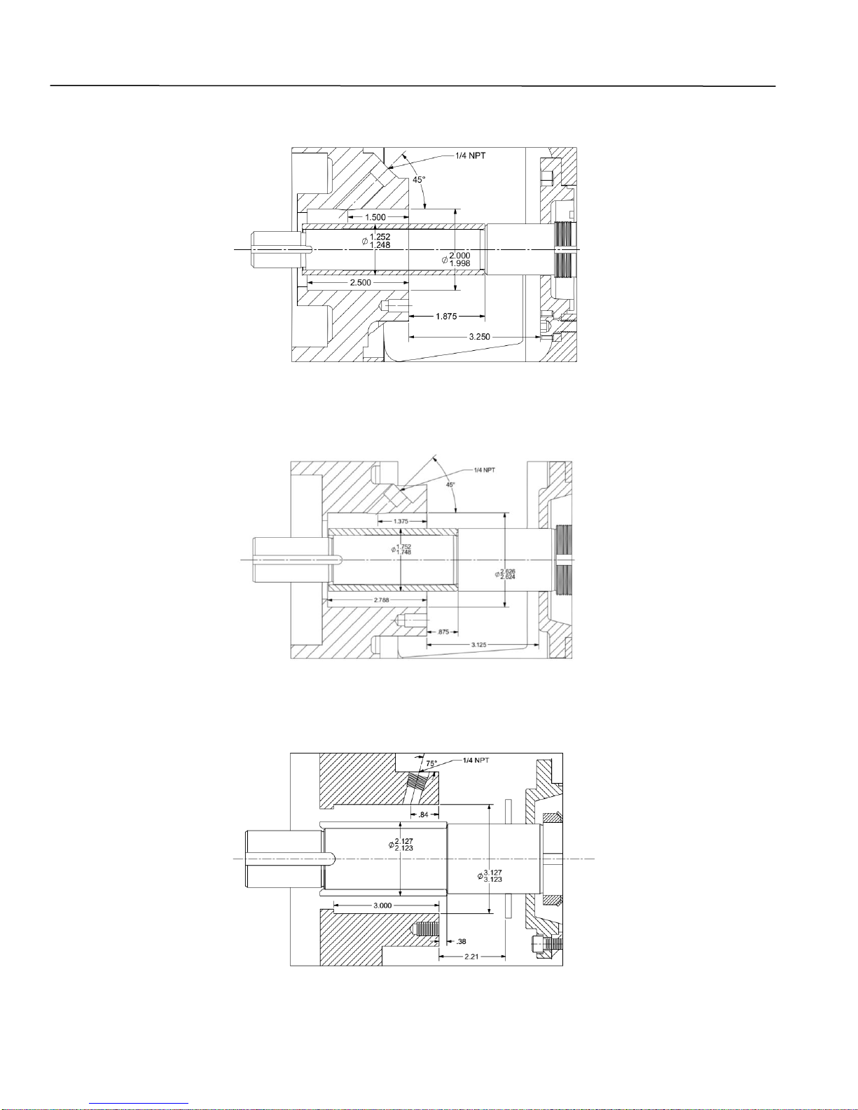
Stuffing Box. The stuffing box, Figure 1, is where the
packing or mechanical seal is located.
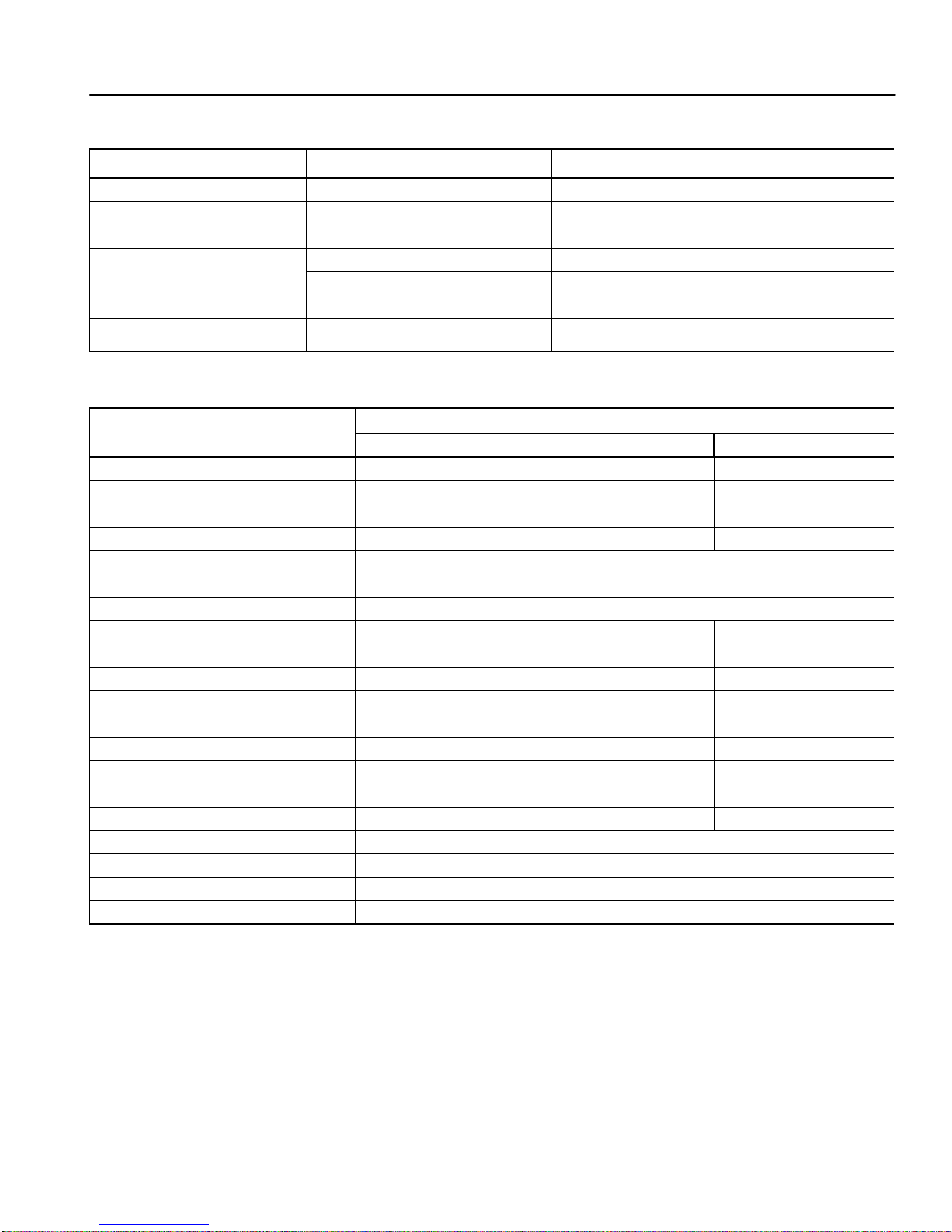
Materials of Construction. The listed material
specifications in Table 2 are referenced for standard
catalog options.
Mechanical Data. The Key Mechanical data in Table 3
lists the maximum allowable horsepower at the
maximum allowable pump shaft speed (3600 RPM).
Dimensions and diameters are reference and given in
inches.
5
Page 12
I-120
GH Pump 120 – 16.02.EN
10P Bearing Frame
20P Bearing Frame
6
30P Bearing Frame
Figure 1. Stuffing Box Dimensions
Page 13
I-120
Component
Material
Specification
Bearing Frame
Cast Iron
ASTM A48, Class 30
Casing
316
ASTM A44, Class 30
Cast Iron
ASTM A48, Class 30
Impeller
Bronze
ASTM B584,C87500
Cast iron
ASTM A48, Class 30
316 SS
ASTM A744, Grade CF-8M
Shaft
Carbon steel
ASTM A108, Grade 1215
Item
Bearing Frame
10P
20P
30P
Max power (BHP) @ 1750 RPM
20
75
250
@ 3600 RPM
40
150
500
Radial bearing type
207
210
211
Thrust bearing type
307
310
5,611
Thrust bearing lube (standard)
Grease
L10 bearing life (hrs) – radial
50,000
- thrust
25,000
Radial to thrust bearing c/l (in.)
6.75
8.50
11.20
Shaft diameter @ coupling
1.250
1.50
2.000
@ radial bearing
1.378
1.968
2.166
@ thrust bearing
1.378
1.968
2.165
@ impeller hub
0.875
1.250
1.625
@ shaft sleeve
1.000
1.375
1.750
Shaft sleeve OD (in.)
1.250
1.750
2.125
Impeller – thrust bearing c/l (in.)
8.00
9.00
9.63
Rotor WR2 (lb – in.) - shaft
0.014
0.058
0.126
7” impellers
15.10
10” impellers
56.67
11” impellers
137.56
13” impellers
233.74
GH Pump 120 – 16.02.EN
Table 2. Key Component Materials
Table 3. Key Mechanical Data
7
Page 14

I-120
GH Pump 120 – 16.02.EN
VI. INSPECTION AND STORAGE.
A. INSPECTION. Upon receipt of the shipment,
unpack and inspect the pumping unit and individual
parts to insure none are missing or damaged. Carefully
inspect all boxes and packing material for loose parts
before discarding them. Check to make sure the
shipment complies with the purchase order. Immediately
report any missing parts or damage incurred during
shipment to the factory and to the Transportation
Company and file your “damage and/or lost in shipment”
claim with the carrier.
B. PACKING FOR RETURN. If the pumping unit is
sent back to Carver Pump Company for repair, drain the
unit, and re-seal all flanges and connections that were
covered or plugged. Ship the pump(s) in an assembled
condition to prevent damage to sealing faces of
individual components. A Return Goods Authorization
(RGA) and a Material Safety Data Sheet (MSDS) is
required on all returned pumps. Copies of MSDS
records should be kept and maintained by the customer.
The customer is responsible for cleaning and flushing
the pump before it is returned to the factory. Make sure
to specify the fluid used in the service.
C. STORAGE OF PUMP. If the equipment is not to be
immediately installed and operated, store it in a clean,
dry, well ventilated place, free from vibrations, moisture
and rapid or wide variations in temperature.
NOTE
CAUTION
A pump which is made of iron or steel that sits
in extreme heat, high humidity, or full or
partially full water over 30 days will rust and will
most likely seize. If the pump rusts and/or
seizes, a complete overhaul and repair may be
necessary to refurbish the pump.
Consider a unit to be in storage when:
1. It has been delivered to the job site and is
waiting to be installed.
2. It has been installed but operation is delayed
pending completion of construction.
3. There are long (30 days or more) periods
between operating cycles.
4. The plant (or department) is shut down for
periods of longer than 30 days.
Measures to be taken for prolonged shutdown of
installed pumping unit. If the pumping unit remains
installed a periodic check of operation is in order to
make sure that the pump is always ready for instant
start-up and to prevent the formation of deposits within
the pump and the pump intake area. Start up the
pumping unit regularly once a month or once every 3
months for a short time (approximately 5 minutes)
during prolonged shutdown periods. Prior to operation
check run ensure that there is sufficient liquid available
for operating the pump.
Storage requirements vary depending on
climatic environment, length of storage and
equipment. For storage periods of three months
or longer, contact manufacturer for specific
instructions. Improper storage could damage
equipment and would result in non-warranty
covered restoration of non-warranty covered
product failures.
When storing the pump up to three months rotate the
shaft for several revolutions at least once per month to
coat the bearings with lubricant, retard oxidation and
corrosion, and prevent possible false brinelling.
The motor bearings should be prepared for storage
according to the motor manufacturer’s instructions, in
the motor manufacturer’s maintenance manual, which
should come with the motor.
Interim Storage (Indoors)/Preservation. When the
unit is temporarily put into storage, only the wetted low
alloy must be preserved. Commercially available
preservatives can be used for this purpose. Please
observe the manufacturer’s instructions for
application/removal.
The unit/pump should be stored in a dry room where the
atmospheric humidity is as constant as possible. If
stored outdoors, the unit and crates must be covered by
waterproof material to avoid any contact with humidity.
Protect all stored goods against humidity, dirt, vermin
and unauthorized access!
All openings of the assembled unit components are
closed and must only be opened when required during
installation. All blank parts and surfaces of the pump are
oiled or greased (silicone-free oil and grease) to protect
them against corrosion.
8
Page 15
I-120
GH Pump 120 – 16.02.EN
VII. INSTALLATION.
A. LOCATION. The pump assembly should be
located in an area that will permit periodic inspection
and maintenance. Head room and access should be
provided and all units should be installed in a dry
location with adequate drainage. The discharge piping
should be direct with as few elbows and fittings as
possible.
The pump assembly should be installed as close to the
fluid as possible. A short, direct suction pipe can be
used to keep suction losses at a minimum. If possible,
locate the pump so fluid will flow by gravity to the
suction opening. The discharge piping should be direct
with as few elbows and fittings as possible. The total
NPSHA, which includes the suction lift and pipe friction
losses, must be greater than the Net Positive Suction
Head Required (NPSHR) by the pump.
B. HANDLING.
Figure 2. Transport of the Bare Pump
CAUTION
Use a hoist with adequate lifting capacity. See
pump nameplate for weights.
Do not pick up the complete unit by the motor
or the pump shafts or motor lifting eyes.
If the pumping unit slips out of the sling
arrangement, it may cause injury to personnel
and/or damage to the pumping unit.
Moving the unit requires proper preparation and
handling. Always make sure that the pump or the
pumping unit while being moved cannot slip out of the
transport suspension arrangement. Use a sling for
pumps without bases, refer to Figure 2. To lift a
complete unit, a hoist or suitable lifting device should be
attached to the base, refer to Figure 3. The individual
motor may be lifted using proper eyebolts provided by
the manufacturer, but these should not be used to lift the
assembled unit.
Figure 3. Transport of Coupled Pump
C. FOUNDATION. Make sure that the concrete
foundation has set firmly before placing the unit on it. Its
surface must be truly horizontal and even. The
foundation bolts must be inserted in the baseplate holes.
The foundation should be 3 to 6 inches wider and longer
than the baseplate, have a level surface, and be of
sufficient mass to prevent vibration and form a
permanent rigid support for the unit. The best
foundations are concrete with anchor bolts of adequate
size embedded in the foundation in pipe sleeves having
an inside diameter 2-1/2 times larger than the bolt
diameter. This will allow for accurate positioning of the
unit. Keep the concrete surface clean, yet rough.
9
Page 16
I-120
(If equipped)
GH Pump 120 – 16.02.EN
D. LEVELING OF UNIT. When the pump is supplied
complete with motor and base, the unit is assembled at
the factory. Lower unit onto foundation, positioning base
structure so anchor bolts are aligned in middle of holes
in base.
The base should be supported on either rectangular
metal blocks with shims or on metal wedges having a
small taper. The support pieces should be placed close
to the foundation bolts. Refer to Figure 4, Grouting and
Foundation Bolting. Place supports directly under the
part of the base plate, which carries the greatest weight.
Space the supports closely enough to provide uniform
support of the base plate. Adjust the metal supports or
wedges until the shaft is level. Check suction and
discharge flanges of the pump by means of a level.
Make corrections, as necessary, by adjusting the
supports or wedges under the base plate.
The base should be supported on metal shims or metal
wedges placed directly beneath the part of the base
supporting the most weight. The shims or wedges
should be spaced close enough to give support and
stability.
Adjust metal supports or wedges until suction and
discharge flanges are level.
CAUTION
Do not attempt to straighten the base by using
the anchor bolts.
E. GROUTING. After the pumping unit has been
leveled and the alignment is correct, grout the unit to the
foundation using a high-grade, non-shrinking grout, refer
to Figure 4. Proceed grouting using the following
procedure:
Prepare concrete foundations, anchor bolts and leveling
screws according to individual instructions covering
these items.
1. Wax forms heavily with at least three coats of
paste wax. Forms must be substantial and well
braced. All corners, joints, bottoms must be
sealed with silicone caulk for water tightness. All
forms should have a 45° chamfer strip installed
to prevent stress risers.
2. Anchor bolt-free length must be wrapped with
duct seal or electricians plastic tape to prevent
grout from contacting the bare metal. Grout
sticking to the anchor bolt will prevent the
elongation necessary to develop the hold-down
force. Failure to do this will result in broken
anchor bolts.
3. If equipped leveling screws must be greased to
permit removal prior to the final torque.
4. Do not use shim packs as a leveling device
unless it is planned to remove them prior to final
torque application.
5. Leveling screw pads should be a minimum of
1/2" thick with minimum diameter of 3". Corners
of pad must be rounded to approximately 1/8"
radius to prevent stress cracking. Set leveling
screws on the chipped concrete surface. Set the
pad with quick set cement or resin repair
compound. With jacking bolt pads secure and
level, set and level base with leveling screws. If
not equipped with leveling screws use shims to
level.
6. The underside of the standard factory steel
base plate was painted with epoxy grout primer
and should only require proper cleaning. If the
base must be sandblasted, prepare the contact
faces to SSPC-SP 6 Spec. If base cannot be set
within 24 hours of blasting, the underside must
be coated with a compatible rust inhibitive
primer. Tighten foundation bolts loosely. Allow
the grout to fully cure before firmly
tightening the foundation bolts.
Figure 4. Grouting and Foundation Bolting
10
Page 17

I-120
Parallel Offset Misalignment
Parallel Offset (TIR)
Measurement
Angular Misalignment
GH Pump 120 – 16.02.EN
F. COUPLING ALIGNMENT. The pump and motor
are connected by a coupling. Alignment is necessary
when the pump or motor are removed from the base.
The coupling should NOT be reconnected until the
alignment has been completed. Always check the
coupling alignment after shipping. The following is how
to check the coupling alignment.
NOTE
shims under the feet or supports of the motor and
tighten fastening bolts until correct alignment is
achieved.
1. Move the pump or motor to achieve acceptable
alignment. When properly aligned, the disc
packs will be centered and approximately
parallel to their mating flange faces and the
flexing elements will have little visible waviness
when viewed from the side.
Refer to coupling manufacturer’s manual for
instructions regarding shaft alignment and
recommended installation limits.
Soft Foot – The equipment must rest flat on its
base. If one or more feet of the pump or motor
are shorter, longer, or angled in some way to
prevent uniform contact (a condition commonly
known as “soft foot”) it must now be corrected.
To improve the life of the coupling, the shafts must be
aligned to minimize deflection of the flexing elements.
Shaft alignment is required in the axial, parallel, and
angular directions, with each of these values not to
exceed the recommended installation limits. Shaft
alignment can be measured using various established
methods, including Laser Alignment, Reverse Dial
Indicator, and Rim and Face.
The motor and pump shafts must be accurately aligned
as any misalignment can cause damage to the coupling,
motor, or pump. When the shafts are in correct
alignment, the coupling hubs will be on a common axis,
concentric with each other, and at the correct distance
apart. If the coupling hubs are misaligned, it is general
practice to adjust the driver to the pump. Insert full
NOTE
Refer to the coupling manufacturer’s manual for
recommended installation limits for Parallel,
Angular, and Axial alignment.
2. The “Parallel Misalignment” value (P) is the
offset between the centers of the hubs, as
shown in Figure 5.
3. When the Parallel Offset is measured by
rotating the hubs in unison with dial indicators
as shown in Figure 5, the Total Indicator
Reading (TIR) should be divided by (2) to
calculate (P).
4. It should be noted that parallel offset measured
on the hub surfaces includes misalignment of
the equipment shafting plus any variation (TIR)
in the hubs. This may be helpful to consider
during problem solving for alignment difficulties.
5. The “Angular Misalignment” value is the
maximum difference between the
measurements X and Y taken at opposite ends
of the hub flanges, as shown in Figure 5.
Figure 5. Coupling Alignment
11
Page 18

I-120
GH Pump 120 – 16.02.EN
G. PRE-INSTALLATION PROCEDURES.
DANGER
Before activating the pumping unit, check to
make sure there are no personnel working on
the unit. Serious injury or death to personnel
could result if the unit is activated while being
worked on.
1. Observe all caution or danger tags attached to
the equipment.
CAUTION
Never run the pump dry. Close running fits
within the pump are liquid lubricated. Dry
running will result in pump seizure or damage.
2. Before starting the pump, rotate shaft by hand
to assure all moving parts are free from rubbing.
3. Before starting the pump, install guards to
enclose all exposed rotating parts.
4. Before starting the pump, fill the volute and
suction line with liquid. The pump is being
primed in accordance with Section VIII,
Paragraph B.
5. Before starting a mechanical seal pump
equipped with external flush lines, turn on seal
water, and confirm the seal water is at sufficient
pressure.
6. Make sure all fasteners are torqued to the
proper torque values to avoid equipment
damage and injury to personnel.
H. PIPING. All piping should be independently
supported near the pump so that pipe strain will not be
transmitted to the pumping unit.
Suction lift lines shall be laid with a rising slope toward
the pump and suction head lines with a downward slope
towards the pump.
The suction pipe must be air tight and sloped upward to
pump flange to avoid air pockets which will impair pump
operation. The discharge pipe should be as direct as
possible using a minimum number of valves to reduce
pipe friction losses.
Never use a straight taper (concentric) reducer in a
horizontal suction line because air pockets may form in
the top of the reducer and the pipe. Use an offset
(eccentric) reducer instead.
It is recommended to install a check valve and closing
valve in discharge line and closing valve in suction line,
depending on the type of plant and pump. The check
valve, between the pump and valve, protects pump from
water hammer and prevents reverse rotation in the
event of power failure. Closing valves are used in
priming, starting, and pump shut down. Pump must
never be throttled by use of a valve in the suction line.
Thermal expansions of the pipeline must be
compensated by appropriate measures so as not to
impose any extra loads on the pump exceeding the
permissible pipeline forces and moments. Refer to Table
1 for permissible forces and moments.
I. AUXILIARY PIPING CONNECTIONS AND
GAUGES. In addition to primary piping connections, the
pump may require other connections such as gauges or
drains. All these lines and gauges should now be
installed. Refer to vendor mechanical seal drawing for
seal line connections to the mechanical seal.
J. MOTOR. Refer to motor vendor’s manual for motor
information and information on connecting to the power
supply.
DANGER
CAUTION
All piping connections must be made with the
pipe in a freely supported state. Do not apply
vertical or side pressure to align the piping with
the pump flange.
Before connecting suction, discharge, and auxiliary
piping, check to see that the piping is absolutely clean
internally. Any debris in the piping will be drawn into the
pump passageways and can cause extreme damage.
The internal diameters of the suction and discharge
lines must be equal to the internal diameters of the
pump suction and discharge nozzles.
12
Connection to the power supply must be
effected by a trained electrician only. Check
available main voltage against the data on the
motor rating plate and select appropriate startup method.
K. DIRECTION OF ROTATION. Correct pump rotation
is indicated by an arrow on the bearing frame or
backcover depending on the style of pump that you
have. The standard direction of rotation, viewed from the
motor end, is clockwise.
Page 19

I-120
GH Pump 120 – 16.02.EN
VIII. OPERATION.
Positive Suction Head:
A. PRE-START CAUTIONS.
DANGER
Before activating the pumping unit, check to
make sure there are no personnel working on
the unit. Serious injury or death to personnel
could result if the unit is activated while being
worked on.
1. Before starting or operating the pump, read this
entire manual, especially the following
instructions.
2. Observe all caution, warning or danger tags
attached to the equipment.
3. Rotate both the pump and driver shafts by hand
to assure all moving parts are free.
4. Before starting the pump, install closed guards
around all exposed rotating parts.
5. Check to make sure that fluid in the pump is
free of debris.
WARNING
Never run the pump dry. Close running fits
within the pump are liquid lubricated. Dry
running will result in pump seizure or damage.
6. Before starting a mechanical seal pump
equipped with external flush lines, turn on
mechanical seal water, and confirm the
mechanical seal water is at sufficient pressure.
Running without fluid in the stuffing box may
result in packing/mechanical seal failure.
7. If excessive vibration or noise occurs during
operation, shut the pump down and rotate shaft
by hand. If excessive vibration or noise
continues, consult a Carver representative.
B. PRIMING. Dry running a centrifugal pump can
result in extensive damage and possible seizing. It is,
therefore, imperative that the pump be primed prior to
initial start-up and that prime must be maintained
through subsequent start-stop cycles.
The priming procedure is different for positive and
negative suction head systems. Follow the procedure
listed below.
1. Open the vent on the highest point on the pump
volute.
2. Open all suction valves.
3. Allow liquid to flow from vent hole until all air
bubbles are vented. Then close the vent.
4. The pump is now primed.
Negative Suction Head:
1. Install an ejector or vacuum pump on the vent at
the highest point on the volute.
2. Close the discharge valve.
3. Open the suction valve.
4. Start the ejector or vacuum pump.
5. Allow liquid to flow until a continuous flow is
exhausted from ejector. Then close the valve to
the vent.
6. The pump is now primed.
C. STARTING THE PUMP.
CAUTION
DO NOT operate pumping unit against a closed
discharge system. If pump has any chance of
seeing operation against a closed system, a
bypass system allowing a minimum design flow
should be installed. This bypass will be
satisfactory for short periods of operation. For
extended periods of operation the bypass
should be sized for the minimum continuous
flow required by the pump.
1. Confirm pumping unit is ready to start.
Complete Section VIII, Paragraphs A and B.
2. If unit is equipped with mechanical seal cooling
lines, confirm that the mechanical seal cooling
water is turned on.
3. Open discharge valves slightly, about 1 to 1 ½
turns if pump is being started for the first time or
from being turned off for overhaul.
4. Open valves to pressure gauges in the system.
5. Start electrical power supply to driver. Start the
pump.
6. Slowly open system valves in discharge line and
adjust pressure and flow to the appropriate
operating conditions. Refer to pump nameplate
and system operating procedures for design
point condition.
13
Page 20

I-120
GH Pump 120 – 16.02.EN
D. OPERATING CHECKS.
1. Check for undue vibration or noise. If any
occurs and does not stop within a short period
of time, turn off the pump. For determination of
the cause and its remedy refer to
Troubleshooting in Section IX or consult Carver
Pump Company.
2. Check mechanical seals or packing rings for
leakage.
3. Check for adequate lubricating liquid flow to the
seal or packing.
4. Check that pump is operating within design
criteria and perimeters. Check and record flow
and pressure readings. The flow and pressure
readings should be within the operating system
guidelines and similar to number stamped on
the pump nameplate.
5. Check and record bearing temperature. It
should not exceed 70º C (160º F). Both inboard
(18) and outboard (16) ball bearing
temperatures should be measured and recorded
at a minimum of 15 minute intervals until the ball
bearing temperatures stabilize. Stabilization of
ball bearing temperature can be defined as the
results of three consecutive readings at
approximately 15 minute intervals with no
temperature rise.
6. Check and record power input to the motor.
7. Check and record vibration.
F. INDEFINITE SHUTDOWN.
Stop the pumping unit per Section VIII, Paragraph E.
Remove casing plug to drain casing. Drain all piping if
there is a possibility of liquid freezing. Relubricate
bearings. Provide pump and driver with a protective
cover.
Measures to be taken for prolonged shutdown of
installed pumping unit. If the pumping unit remains
installed a periodic check of operation is in order to
make sure that the pump is always ready for instant
start-up and to prevent the formation of deposits within
the pump and the pump intake area. Start up the
pumping unit regularly once a month or once every 3
months for a short time (approximately 5 minutes)
during prolonged shutdown periods. Prior to operation
check run ensure that there is sufficient liquid available
for operating the pump.
IX. TROUBLESHOOTING OPERATING
PROBLEMS.
If you have followed the installation and starting
procedures outlined in this manual, the pump should
provide reliable service and long life. However, if
operating problems do occur; significant time and
expense can be saved if you refer to Table 3 to
eliminate the most common causes of those problems.
NOTE
E. STOPPING THE PUMP.
WARNING
When pump is handling hazardous fluid,
extreme care must be taken to ensure safety of
personnel when attempting to drain pump.
Suitable protection devices should be used
and/or protective clothing should be worn.
1. If the pump is being stopped for overhaul, slowly
close the discharge valve. Otherwise leave
discharge valves set at condition.
2. Stop the pumping unit in accordance with the
directions on the electrical power supply.
3. Tagout and lockout power to motor according to
OSHA Standard 1910.147.
4. Close discharge and suction valves and any
auxiliary fluid lines.
5. The pumping unit is now off.
Immediate action to be taken before
proceeding with corrective actions in Table 4 is
to stop the pump, refer to Section VIII,
Paragraph E.
14
Page 21

I-120
SYMPTOM
IMMEDIATE ACTION
PROBABLE CAUSE
CORRECTIVE ACTION
Pump does not deliver
rated capacity or rated
head.
1. Stop the pump, refer to
Section VIII, Paragraph
E.
1. Excessive system
pressure.
1. Check GPM and head
against design
conditions; Consult
local distributor or
Carver Pump
Company.
2. Speed to low, motor
speed incorrect, or line
voltage to low.
1. Correct motor speed.
2. Adjust belt tension.
3. Check electrical supply
and correct as
necessary.
3. Valves are not fully
open or plugged
discharge line.
1. Open valves and if
necessary, lock valves
open to prevent
accidental closure.
2. Inspect and clean
discharge.
4. Clogged impeller.
1. Disassemble pump and
clean impeller, if
necessary.
5. Reverse rotation.
1. Check power
connections to motor.
6. Motor running on two
phases only.
1. Replace defective fuse.
2. Check electrical cable
connections.
7. Excessive wear of
internal parts.
1. Disassemble pump,
inspect and replace
worn parts.
8. Liquid level in tank to
low.
1. Increase liquid level in
tank.
9. Vent in suction cover
plugged.
1. Clean vent.
Leakage at case joints.
1. Stop the pump, refer to
Section VIII, Paragraph
E.
1. Gaskets damaged.
1. Disassemble pump and
replace gaskets.
Bearings run hot.
1. Stop the pump, refer to
Section VIII, Paragraph
E.
1. Bearing setting
incorrect.
2. Worn bearings.
1. Correct bearing axial
clearance.
1. Replace bearings.
GH Pump 120 – 16.02.EN
Table 4. Pumping Unit Troubleshooting
15
Page 22

I-120
SYMPTOM
IMMEDIATE ACTION
PROBABLE CAUSE
CORRECTIVE ACTION
Pump discharge pressure
excessive.
1. Stop the pump, refer to
Section VIII, Paragraph
E.
1. Excessive speed.
1. Check speed precisely.
Decrease speed.
2. Pump is pumping fluid
with specific gravity in
excess of that
specified. (If
temperature of fluid is
lower, then specified
specific gravity will be
higher.)
1. If prescribed fluid
temperature or specific
gravity cannot be
attained, one or more
of the following
measures can be
taken:
a. Partially close
discharge valve,
reducing pump
capacity to a point
where driver is not
overloaded.
b. Install more powerful
driver. Consult
Carver Pump
Company specifying
exact operating
conditions.
Pump overloads motor.
1. Stop the pump, refer to
Section VIII, Paragraph
E.
1. Speed too high.
1. Check pumps RPM
and determine correct
sheave and belts for
proper speed. Consult
local distributor or
Carver Pump
Company.
2. Pump discharge
pressure is lower than
design point, therefore
pump's volume too high
(check pump
nameplate).
1. Partially close
discharge valve until
pressure at discharge
flange is as specified.
Decrease speed if
driver remains
overloaded.
3. Same as 2 under
“Pump Discharge
Pressure Excessive.”
1. Same as 2 under pump
discharge pressure
excessive.
GH Pump 120 – 16.02.EN
Table 3. Pumping Unit Troubleshooting - Continued
16
Page 23

I-120
GH Pump 120 – 16.02.EN
X. MAINTENANCE.
Generally the pump does not need continuous
supervision. The pump should always run quietly and
smoothly, without vibration. Regular checks of the pump
running noises will prevent the risk of excessive
temperatures as a result of bearings running hot or
defective bearing seals. To ensure such operation, the
following maintenance schedule should be applied at
regular intervals during operation of the pump.
Occasional visual checks are recommended. Data
should be recorded periodically for each pump to keep
track of maintenance which has been performed and to
note operational problems. A sample maintenance
record sheet is provided for this purpose at the front of
this manual.
NOTE
12,500 Hours - Overhaul
For pump overhaul, complete Section XI, Service
and Repair.
A. LUBRICATION OF PUMP BEARINGS.
Ball Bearing (16 and 18). The pump ball bearings (16
and 18) are grease lubricated.
Grease, lubrication frequency depends on operating
conditions. Normal duty calls for lubrication after 1,000
hours and every 10,000 hours afterwards. Ball bearings
is lubricated at Carver Pump Company with Amoco
Rykon Premium Grease No. 2EP or equivalent, nonsoap, polyurea thickened grease with a drop point of
450 degrees F. This grease was selected because of its
suitability for extreme pressures and its high
temperature stability. Never mix greases with differing
properties.
Regular inspection and service are essential for
safe operation of the pump. Any auxiliary
systems installed must be monitored, if
necessary, to make sure they function
correctly.
Parts marked with * are options or vary by
pump.
Daily Inspection:
Visually inspect unit.
Check bearing temperatures.
Check for leakage at mechanical seal.
Weekly Inspection:
Check power (amps) readings.
Check pump discharge pressure.
Check vibration on pump and driver bearings.
Vibration should NOT exceed 1.5 of overall
displacement (unfiltered) peak to peak mils
(0.001”) at 3600 RPM and 3.0 of overall
displacement (unfiltered) peak to peak mils
(0.001”) at 1750 RPM.
Monthly Inspection:
Check foundation bolts.
Semi-annual Inspection:
Grease bearings. DO NOT OVER GREASE.
If stand-by pumps are installed, it is advisable to
operate pumps on a rotational system to give
each pump a periodic duty. This ensures that
stand-by pumps will have periodic operation and
always be in good condition for instant start-up.
Polyurea based greases are NOT compatible with
lithium or soda soap based greases. Therefore, the type
of grease added should not vary. However, if it is
necessary to change grease types, the bearing cap (11)
should be thoroughly cleaned and flushed with suitable
solvent to remove all traces of old grease. Disassemble
pump according to Section VII, Paragraph B, remove
shaft and ball bearings (16 and 18) from bearing frame
(19) and follow these procedures:
NOTE
It is recommended that when ball bearings are
removed from the shaft, the ball bearing should
be replaced. If the ball bearing is in good
condition and must be reused, follow the
procedures below.
1. Place ball bearing (16 and/or 18), bearing frame
(19), and bearing cap (35) in a wire or mesh
basket and suspend the basket in a light mineral
solvent. Allow it to soak, preferably overnight.
2. After soaking and cleaning the ball bearing (16
and/or 18), bearing frame (18) and bearing cap
(35) should be rinsed in a clean, light mineral
solvent and agitated vigorously to remove all
loosened hard grease and dirt.
3. Dip ball bearing (16 and/or 18) in clean, light oil
and spin by hand to determine that all foreign
matter has been removed.
4. After cleaning, repack ball bearing (16 and/or
18) half full on both sides with a good quality
bearing grease.
5. Proceed with reassembly of pump according to
Section VII, Paragraph E.
17
Page 24
I-120
Bolt Size
Material
Composite
Steel (or
otherwise noted)
316 Stainless
Steel
¼”-20 5 5
7
5/16”-18
11
11
12
3/8”-16
18
18
21
½”-13
33
39
45
5/8”-11
54
83
97
¾”-10
80
105
132
7/8”-9
109
160
203
1”-8
144
236
300
Tools
Materials
Test Equipment
Spanner Wrench
Rawhide or
Wood Mallet
Grease,
Polyurea
base
Belt Alignment
Gauges
Volt-Amp Meter
Wooden Wedge
Allen Wrench Set
O-ring
Lubricant
Belt Tension
Gauge
Socket, Open, &
Box Wrench
Set
Rust Solvent
Dow 111
Lubricant
Vice Grips
Torque Wrench
Bearing Heater
GH Pump 120 – 16.02.EN
To lubricate ball bearing (16 and/or 18) use the following
procedure:
CAUTION
Over greasing creates heat and is the cause of
many problems requiring repair. DO NOT
OVER GREASE.
1. Never lubricate ball bearing (16 and/or 18) while
unit is running. If necessary, shut down pumping
unit according to Section IV, Paragraph E.
CAUTION
Do not lubricate bearing with a power grease
gun.
2. Using a hand-operated grease gun on grease
fittings, add approximately one ounce of fresh
grease. With most hand-operated grease guns,
two or three pumps are enough. DO NOT
OVER GREASE. When installing new bearing,
pack new bearing only half full with grease.
Bearing temperature may rise above normal
immediately after lubrication, but should
stabilize within 4 to 8 hours.
B. LUBRICATION OF MOTOR BEARINGS. See
motor manufacturer’s instructions to be sure motor ball
bearings are properly lubricated.
C. TORQUE VALUES. Refer to Table 5,
Recommended Torque Values. Clean and properly
lubricate threads and bearing face of the fastener to
obtain the proper fastener loading from these torque
values. Fasteners should be tightened evenly and in
stages. Refer to your torque wrench manual for the
proper use of your wrench.
Table 5. Recommended Torque Values (ft-lbs)
Table 6. Recommended Equipment
XI. SERVICE AND REPAIR.
Refer to Figures 9 and 10 to locate the pump parts by
item number and parts list Table 8. If a specific sectional
assembly drawing exists for a particular pumping unit
then that drawing should be referred to for service work.
A. PREPARATIONS FOR DISASSEMBLY OF PUMP.
During disassembly, match mark parts so they can be
replaced in their original position. All parts should be
thoroughly cleaned or replaced with new, if necessary.
Sealing faces should be perfectly clean.
CAUTION
Factory authorized parts must be used to safely
maintain your Carver Pump.
NOTE
To avoid damage to O-rings, check to make
sure all parts are free of sharp edges or burrs.
All O-rings, ball bearings, shims, mechanical
seals, lip seals, packing, and gaskets if
disturbed from position should be replaced.
18
Variations do exist between configurations, not
all parts described in the text may be on your
configuration. Review what variations your
pumping unit has before starting. Parts marked
with * are options or vary by pump.
After prolonged operation, components may not be
easily removed from shaft. In such instances, rust
solvent may be used and suitable extracting tools
applied wherever possible. DO NOT use force under
any circumstances. Refer to Table 6, Recommended
Equipment, for proper tooling during disassembly and
Page 25

I-120
GH Pump 120 – 16.02.EN
assembly. Refer to appropriate sectional drawing for
location of parts followed by an item number.
DANGER
Prepare the pumping unit for disassembly using the
following list:
1. Read this entire section and study the
applicable sectional view drawing and parts list
before disassembling the pump.
2. Stop the pumping unit; refer to Section VIII,
Paragraph E.
DANGER
Before attempting to disassemble the pump,
the electrical power supply to the driver must
be locked and tagged in the “OFF” position to
prevent injury or death to personnel servicing
the pumping unit.
3. Remove terminal box cover. Disconnect motor
leads. Reconnect terminal box cover.
4. Remove splashguard (131A) from bearing
frame (*19) or intermediate (*71).
NOTE
Refer to cartridge seal (90*), refer to vendor
instructions for proper mechanical seal removal
procedure.
5. For cartridge mechanical seals (90*), reinstall
seal clip.
6. Close suction and/or discharge valves. Shut off
and close all valves controlling flow of liquid to
and from pump. The pump should be cooled
down to ambient temperature. The casing must
be empty and not under pressure.
Be sure to adequately support the piping prior
to disconnecting the pumping unit. Failure to
adequately support the piping could result in
serious injury or death to personnel and/or
damage to the pumping unit.
8. Disconnect piping, gauge lines, and auxiliary
connections, as necessary.
B. DISASSEMBLY OF PUMP. The instructions that
follow are an aid for properly trained personnel to
service your Carver Pump. Refer to Figures 9 and 10 to
locate the pump parts by item number and parts list
Table 9. If a specific sectional assembly drawing exists
for a particular pumping unit then that drawing should be
referred to for service work. Read this entire section
before disassembling the pump.
NOTE
Refer to Section II for Safety precautions before
disassembling pump.
Variations do exist between configurations, not
all parts described in the text may be on your
configuration. Review what variations your
pumping unit has before starting. Parts marked
with * are options or vary by pump.
After completion of disassembly, all parts should be
thoroughly cleaned or replaced by new ones if
necessary. All gaskets and sealing faces should be
perfectly clean. When cutting new gaskets, make sure
they are exactly the same thickness as the old ones
unless noted.
DANGER
When pump is handling hazardous fluid,
extreme care must be taken to ensure safety of
personnel when attempting to drain pump and
piping before disconnecting the pumping unit.
Suitable protection devices should be used
and/or protective clothing should be worn.
Applicable hazardous material procedures must
be followed.
7. Drain casing (1) by removing casing plug (422
or 423) to remove any remaining fluid. If
necessary, flush pump to remove corrosive or
toxic pumpage. Collect and dispose of corrosive
or toxic material appropriately. Reinstall plug in
casing when fluid is completely drained.
19
Page 26

I-120
GH Pump 120 – 16.02.EN
CAUTION
Use a hoist with adequate lifting capacity; refer
to Section VII, Paragraph B, for lifting the
complete unit.
When pump is handling hazardous fluid,
extreme care must be taken to ensure safety of
personnel when attempting to drain pump and
piping before disconnecting the pumping unit.
Suitable protection devices should be used
and/or protective clothing should be worn.
Applicable hazardous material procedures must
be followed.
NOTE
Mark or number each component while
dismantling according to sequence.
The individual components should be
unscrewed or removed.
1. Complete Section XI, Paragraph A before
continuing with disassembly.
2. Remove coupling guard (*131) and disconnect
coupling (*42) from frame mounted pump.
3. Disconnect tubing and tube fittings, as
necessary.
CAUTION
Use a hoist with adequate lifting capacity; refer
to Section VII, Paragraph B, for lifting the
complete unit.
4. Unbolt bearing frame (*19) or motor (*200) from
base and move pumping unit to open working
area.
5. Remove splash guard (131A) from motor
adaptor (71*) if splash guard hasn’t already
been removed.
NOTE
Take special care during disassembly with the
mechanical seal rotary and stationary elements
when removing the casing off the shaft.
6. On frame-mounted pumps, remove capscrews
(600*) from backcover (11) and casing (1).
Remove rotary assembly from casing and take
to a suitable work area.
7. On close-coupled pumps, remove nut (600*)
from bolt (601*) from motor adaptor (71),
backcover (11) and casing (1). Remove rotary
assembly along with motor and take the items to
a suitable work area.
8. Remove hex nuts (615) and flat washers (645)
from studs (630). Slide gland (17) towards
slinger (40) to release tension on mechanical
seal (*90) or slide back and remove gland
halves from packing rings (*180).
9. Remove impeller capscrew (26), impeller O-ring
(89C), impeller washer (28), and impeller gasket
(73X). The best tool to remove impeller
capscrew is a hex wrench welded to a socket
head.
10. Remove impeller (2 or 3) from shaft (*6).
Remove impeller key (32).
11. Remove capscrews (*601) from bearing frame
(*19) and motor adaptor (*71). Remove
backcover from motor adaptor and from shaft
(*6). Remove O-ring (89) from backcover and
discard.
NOTE
Refer to mechanical seal (*90) vendor
instructions for proper mechanical seal removal
procedure.
DO NOT remove rotating element of
mechanical seal (*90) from shaft sleeve (*14),
at this point, especially if mechanical seal is
relatively clean and in good working condition.
12. On pumps equipped with mechanical seal (*90),
remove seal spacer (*68), sleeve gasket (73),
and shaft sleeve (*14) with mechanical seal
from shaft (*6). Inspect rotating element of
mechanical seal before removing from shaft
sleeve. If replacement is required remove
rotating element of mechanical seal from shaft
sleeve.
13. Remove old packing (*180), lantern ring (*29)
and packing retaining ring (*63) from backcover
(11).
14. Remove gland (17), and O-ring (89X) from shaft
(*6).
15. Remove slinger (40) from shaft (*6). If the
slinger is damaged and needs replaced or it is
necessary to replace the ball bearings (*16 or
*18).
16. Remove capscrews (605) and remove motor
adaptor (71) from motor.
20
Page 27

I-120
GH Pump 120 – 16.02.EN
NOTE
If gaskets are disturbed from position replace
with new.
7. Inspect mechanical seal. Replace the
mechanical seal that is disturbed from position
or damaged.
8. Inspect the impeller and bushing keys for
The following steps are for pumps with a
bearing frame.
distortion and push fit into keyways. The keys
should be square on all four edges. They should
fit without having to be forced. The keys should
17. Remove socket head bolt (*608) fastening
bearing cap (*35) to bearing frame (*19).
Remove bearing cap from bearing frame.
18. Remove coupling (*42) from shaft (*6).
19. Remove the shaft (*6) (with radial and thrust ball
bearing assemblies) from the bearing frame
(*19).
20. Uncrimp tang on bearing lockwasher (*69) and
remove bearing locknut (*22) and bearing
lockwasher.
NOTE
If ball bearings are disturbed from position
replace with new.
not rock in keyway. Replace keys or shaft if
necessary.
9. Inspect ball bearings (16 and 18) for damage. A
damaged bearing must be replaced. If a bearing
is removed from the shaft, it is recommended
that the bearing be replaced. If bearing
replacement is not possible and bearing is in
good condition bearing should be cleaned and
protected until ready to use. Refer to Section X,
Paragraph A.
10. Check the shaft sleeves and spacer sleeves
visually for score marks, scratches, pits,
grooves or burrs. Touch up sleeves with
polishing cloth and inspect for remaining
grooves or deep scratches. Remove burrs with
a file. Shaft sleeves and spacer sleeves should
21. If desired, pull ball bearing (*18) from shaft (*6).
22. If desired, pull ball bearing (*16) from shaft (*6).
be replaced if any marks, pits or grooves are
still visible after touching up.
11. Inspect tubing for kinking. Replace kinked
C. PARTS INSPECTION.
tubing.
12. If the impeller shows excessive wear due to
1. All parts should be thoroughly cleaned with a
suitable solvent or replaced with new ones if
necessary.
2. All sealing faces should be perfectly clean. All
ball bearings, mechanical seals, gaskets, Orings, lip seals, and locking devices with a
nylock feature are to be replaced with new if
disturbed from position.
3. Check shaft for runout, scratches, grooves, or
any possible damage. Touch up scratches and
grooves with a polishing cloth and inspect for
remaining grooves or deep scratches. A bent or
excessively damaged shaft should be replaced.
4. Inspect the casing for pitting, scoring, and
erosion. The inside of the casing should be free
of any pits or grooves. The maximum allowable
depth is 1/8” (3mm). Replace the casing if any
of these defects are present.
5. If the suction cover on an open impeller pump
shows excessive wear on the face due to
abrasion or corrosion, and performance cannot
be restored, replace suction cover.
6. Inspect and replace any defective grease
fittings.
erosion or pitting, so that performance cannot
be restored, it must be replaced. If a new
impeller is installed, check to make sure that it is
balanced and of the correct trim. If an impeller is
restored or replaced check the dynamic balance
of the rotor before reassembly of the pump.
13. If enclosed impeller (2) is equipped with optional
wear rings, check the wear ring clearance as
follows:
a. Measure outside diameter of front impeller
hub (2) in three places.
b. Measure inside diameter of wear ring (7) in
three places.
c. If difference between the high reading of the
inside diameter of the wear ring (7) and the
low reading of the outside diameter of the
impeller (2) wear ring exceeds double the
new maximum clearances given in Table 6,
replace the wear ring according to Section
XI, Paragraph G.
d. Measure outside diameter of back impeller
hub (2) in three places.
e. Measure inside diameter of the backcover
wear ring (7X) in three places.
21
Page 28

I-120
Pump Size
Front Wear Ring Clearance
(Inches)
Back Wear Ring Clearance
(Inches)
1-1/4 x 1 x 7
.012/.016
N/A
1-1/2 x 1-1/4 x 7
.014/.018
N/A
2-1/2 x 2 x 7
.012/.016
N/A
3 x 2-1/2 x 7
.014/.018
N/A
4 x 3 x 7
.014/.018
.012/.016
5 x 4 x 7
.015/.020
.012/.016
1-1/2 x 1-1/4 x 10
.011/.014
N/A
2 x 1-1/2 x 10
.012/.016
N/A
2-1/2 x 2 x 10
.012/.016
N/A
3 x 2-1/2 x 10
.012/.016
.012/.016
4 x 3 x 10
.012/.016
.012/.016
5 x 4 x 10
.012/.016
.012/.016
6 x 5 x 10
.021/.026
.021/.026
2 x 1 x 11
.012/.015
.012/.015
4 x 2 x 11
.016/.020
.016/.020
4 x 3 x 11
.016/.020
.016/.020
5 x 4 x 11
.016/.020
.016/.020
8 x 6 x 11
.019/.023
.019/.023
2-1/2 x 1-1/2 x 13
.020/.023
N/A
2-1/2 x 2 x 13
.020/.024
.020/.024
3 x 2-1/2 x 13
.016/.020
.014/.018
4 x 3 x 13
.017/.020
.014/.018
5 x 4 x 13
.018/.022
.014/.018
6 x 5 x 13
.017/.021
.014/.018
8 x 6 x 13
(frame mounted only)
.019/.022
.014/.018
GH Pump 120 – 16.02.EN
f. If difference between the high reading of the
inside diameter of the backcover wear ring
(7X) and the low reading of the outside
diameter of the back impeller (2) wear ring
Table 7. Enclosed Impeller Clearance
exceeds double the new maximum
clearances given in Table 7, replace the
back wear ring according to Section XI,
Paragraph G.
22
Page 29

I-120
GH Pump 120 – 16.02.EN
D. REASSEMBLY OF PUMP. Read this entire section
before reassembling the pump. The instructions that
follow are an aid for properly trained personnel to
assemble your Carver Pump. Refer to Figures 9 and 10
to locate the pump parts by item number and parts list
Table 9. If a specific sectional assembly drawing exists
for a particular job then that drawing should be referred
to for assembly. Refer to Table 5 for recommended
torque values. Assemble the pump in accordance with
accepted rules of engineering practice. Coat individual
components with a suitable lubricant before assembling.
Assembly of unit should be performed on a clean, flat
surface. During reassembly, install parts as applicable.
Replace bearing (*16 or *18), once removed
from shaft (*6). If ball bearing replacement is
not possible and bearing is in good condition,
clean bearing in accordance with Section X,
Paragraph A.
1. If removed, hand pack ball bearings (*16 and/or
*18) half full with the proper grease, refer to
Section X, Paragraph A. Install ball bearings
onto shaft (*6) with open sides of ball bearings
facing away from larger diameter of shaft.
NOTE
2. Install bearing lockwasher (*69) and bearing
locknut (*22) on inboard end of shaft. Crimp
CAUTION
tang of bearing lockwasher into one of the
grooves provided in the bearing locknut.
During reassembly, install new O-rings, ball
bearings, packing, mechanical seals and
gaskets if disturbed from position. O-rings, ball
bearings, packing, mechanical seals and
gaskets may have been damaged during
disassembly.
3. Install the shaft (*6) in the bearing frame (*19).
4. Install bearing cap (*35) on bearing frame (*19)
securing it to the bearing frame with capscrews
(*608). Refer to Table 5 for recommended
torque values.
5. Lubricate pump by inserting grease into grease
While installing ball bearings, DO NOT
unnecessarily hit ball bearings. If damage to
ball bearings occurs, replace damaged ball
bearings with new ball bearings.
zerks (*76), refer to Section X, Paragraph A.
6. If removed, install the slinger (40) on shaft (*6)
next to motor adaptor (71).
7. Lubricate and install sleeve O-ring (89X) onto
shaft (*6).
After 12,500 hours of service, replace the ball
bearings.
NOTE
NOTE
To ensure proper seating of ball bearing parts,
rotate the ball bearing while clamping the parts.
All parts should be thoroughly cleaned or
replaced with new ones if necessary. All
sealing faces should be perfectly clean, but do
not scratch or alter surface finish on seal faces.
Variations do exist between configurations, not
all parts described in the text may be on your
configuration. Review what variations your
pumping unit has before starting. Parts marked
with * are options or vary by pump.
For close-coupled units start reassembly with
step 7.
Refer to mechanical seal vendor instructions for
complete seal installation procedure.
8. As applicable, the stationary element of
mechanical seal (*90) should be installed in the
gland (17) before the gland is installed, refer to
Section XI, Paragraph F for procedures. Install
gland on shaft (*6), slide back towards slinger
(40).
9. If mechanical seal (*90) was removed lubricate
outside of shaft sleeve (14) to facilitate
mounting of mechanical seal. Install mechanical
seal on shaft sleeve. Rotating element of
mechanical seal if not being replaced will be on
shaft sleeve.
10. Coat shaft sleeve (14) bore with DOW 111 and
install shaft sleeve over O-ring (89) onto shaft
(6).
23
Page 30

I-120
GH Pump 120 – 16.02.EN
NOTE
For a cartridge seal, refer to mechanical seal
vendor instructions for proper seal installation
procedure.
11. If applicable, install cartridge mechanical seal
(*90). DO NOT remove seal clip until after pump
assembly is complete.
12. For units with packing (*180), install the packing
retaining ring (*63) into the backcover (11).
Install the lantern ring (*29) on the shaft sleeve
(14) sliding the lantern ring back near the slinger
(40).
13. As applicable, install the mechanical seal
spacer (*68) or packing retaining ring (*63) onto
shaft sleeve (14).
14. Install sleeve gasket (73).
15. Install O-ring (89) on backcover (11).
16. Install backcover (11) on motor adaptor (*71)
and secure with capscrews (601).
CAUTION
During steps 17 through 21b, use old impeller
capscrew (26) to secure impeller (2 or 3). Once
proper impeller clearance is achieved, use a
new impeller capscrew (26) to secure impeller.
During assembly, install new impeller capscrew
(26) with locktite.
NOTE
Impeller gasket installation is critical to Dry
Shaft design. Insufficient gasket thickness may
allow liquid to access the end of the shaft.
Excessive gasket thickness may allow liquid
ingress to shaft area behind the impeller. DO
NOT reuse PTFE gaskets.
17. Install impeller key (32). Coat impeller (2 or 3)
bore with DOW 111 and install impeller. Install
impeller washer gasket(s) (73X) in impeller bore
over the end of the shaft (*6), combining
thicknesses and quantities, as required, so the
outer most gasket face protrudes from the
impeller bore by approximately .02 to .04 inches
when the impeller/sleeve/gasket are lightly
compressed. Install impeller capscrew O-ring
(89C) and impeller washer (28) on impeller
capscrew (26). Install and properly torque
impeller capscrew (26).
CAUTION
Use a two-man lift or suitable lifting device to lift
pumping unit, motor, or assemblies.
18. Install casing (1) to backcover (11) with
capscrews (600).
19. Using appropriate leveling tools, level casing.
Torque capscrews (601), (605), and (600), refer
to Table 5.
NOTE
On pumps equipped with a closed impeller,
omit steps 20 through 21d. Steps 20 through
21d are procedures that describe impeller
clearance adjustment for semi-open impellers
only.
20. Install suction cover (9 or 10) to casing (1). DO
NOT install suction cover gasket (73A).
21. There must be a clearance of 0.010 inches
minimum and 0.020 inches maximum between
open impeller (3) and suction cover (9 or 10). To
check clearance, rotate shaft by hand and listen
for any rubbing noise.
If rubbing noises are present, the clearance
between impeller and suction cover is less than
0.010 inches. To remedy this:
a. Remove capscrews (611) and suction
cover (9 or 10).
b. Install new suction cover gasket (73A)
on suction cover (9 or 10).
c. Install suction cover (9 or 10), securing
with capscrews (611).
d. Recheck the clearance and repeat the
above steps as necessary to correct the
clearance between the impeller (3) and
the suction cover (9 or 10) and there is
no more rubbing. The maximum
number of suction cover gaskets (73A)
to be used is 5. Consult with the factory
if more than 5 are needed.
22. After proper clearance is achieved make sure
that the suction cover (9 or 10) is installed with
the vent hole to the top and tighten capscrews
(611).
23. Complete mechanical seal (*90) or packing
(*180) installation. As applicable, ensure tap
flush lines in gland (*17) is positioned so flush
lines can be connected. Install gland on studs
(630) and evenly tighten gland hex nuts (615)
24
Page 31
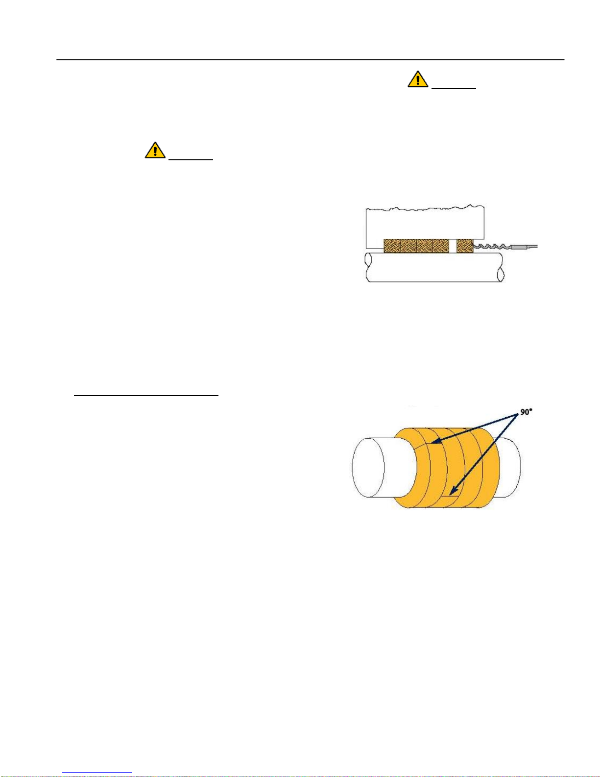
I-120
GH Pump 120 – 16.02.EN
and gland flat washers (645) .Install tubing and
tubing fittings, as applicable.
24. Check for smooth shaft rotation. Install splash
guard (*131A) in bearing frame (*19) or
intermediate (*71).
Do not use system pressure to blow out
(remove) packing.
CAUTION
5. Refer to Figure 6; remove all old packing rings
CAUTION
(180) by using the proper size packing removal
hook. The lantern ring (29) will remain on the
Use a hoist with adequate lifting capacity; refer
to Section VII, Paragraph B, for lifting the
shaft (6) and should be slid to near the slinger
(40).
pump.
25. Return pumping unit to installation site. Install
pumping unit on its base and secure to base
with foundation bolts.
26. On frame-mounted pumps, align coupling (*42)
in accordance with Section VII, Paragraph F.
Reconnect coupling. Install coupling guard
(*131).
Figure 6. Removing Packing with Hook
27. Reconnect piping and gauges, as necessary.
Remove all tags from valves and switches.
Open system valves. Reconnect power supply
to motor.
28. Start pumping unit in accordance with section
IV, Operation.
E. REPLACEMENT OF PACKING. Pumps equipped
with packing have a lantern ring which is located in line
6. Check the shaft (6) for nicks and score marks;
repair or replace as necessary.
7. If required, clean the stuffing box bore.
8. Install the first ring of packing (180) with joint at
approximately the 1 o’clock position (30° right of
vertical). Refer to Figure 7 for packing
alignment.
with the flush water connection on the stuffing box. Flow
should be adjusted, typically to 20 to 30 drops per
minute. Flush water pressure should be approximately
70 kPa (10 PSI) more than the pump discharge
pressure to ensure flow of water through the packing.
Use the following procedure when replacing the
packing:
1. Ensure the new packing is of proper type and
size.
a. Typical is five rings, 6mm x 6mm (3/8” x
3/8”).
b. Standard shaft diameter is 32mm (1 1/4”).
c. Pre-cut sets of packing and lantern rings
are available for stock from Carver Pump
Company
2. Stop the pumping unit; refer to Section VIII,
Paragraph E.
3. Carefully bleed off pressure and remove splash
guard (*131A).
4. Remove gland hex nuts (615) and the gland flat
washers (645) on studs (630). Slide back and
remove gland (17) halves.
Figure 7. Packing Alignment
9. Twist the ring of packing (180) slightly in an “S”
shape and place it around the shaft (6).
10. Seat packing (180) firmly against bottom of
stuffing box using the gland (17).
11. Repeat procedure as described in Steps 8
through 10. Packing (180) ring joints should be
staggered 90° apart.
12. Install enough rings (typically 2) until lantern ring
will align with flush water port.
13. Slide lantern ring (29) back up shaft (6) into
position.
25
Page 32
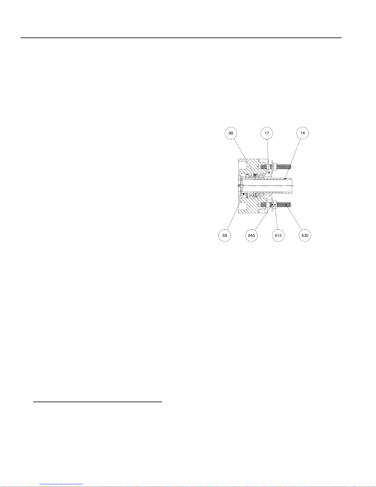
I-120
GH Pump 120 – 16.02.EN
14. Install remaining packing (180) as described in
Steps 8 through 10 above.
NOTE
In tightening the gland (17), gland hex nuts
(615) should be adjusted evenly to avoid
cocking the gland and subjecting the packing
(180) to uneven pressure.
15. Seat final ring of packing (180) firmly with the
gland (17) halves. Install the gland flat washers
(641) and gland hex nuts (615) on studs (630)
using a wrench to tighten.
16. Ensure that lantern ring (29) is still properly
aligned with the flush port.
17. Loosen gland hex nuts (615) and retighten,
using only fingers.
18. At minimum the gland (17) should be into the
stuffing box approximately 3 - 5mm (1/8” 3/16").
19. The remaining exposed portion of gland (17)
follower should be at least 6mm (1/4”) to allow
future gland adjustments.
20. Rotate shaft (6) by hand to ensure shaft is not
binding.
21. Allow liberal leakage at start up.
22. Slowly adjust leakage to an acceptable level by
tightening gland hex nuts (615) slowly and
evenly. Final adjustments should be made by
rotating gland hex nuts one flat at a time.
NOTE
If stuffing box is hot to the touch (approximately
65°C or 150°F), there is not enough flush water
entering the stuffing box.
23. Packing (180) may run warm during break-in
period, one day or two.
24. Do not adjust the packing (180) unless
necessary.
25. If uncontrolled excessive leakage occurs,
lantern ring (29) is pushed out of alignment with
flush water port, or gland (17) follower cannot
be tightened further; re-pack the pump.
F. REPLACEMENT OF MECHANICAL SEAL. A
mechanical seal (90) must be installed and serviced
while the casing (1) is removed from the motor or
bearing frame (19) or intermediate (71).
Mechanical Seal Removal
NOTE
Refer to mechanical seal vendor instructions for
proper mechanical seal removal procedure.
Disassemble pump per Section XI, Paragraph B. steps 1
through 11. Take special care with the mechanical seal
(90) rotary and stationary elements when sliding the
casing (1) off of the shaft (6).
Figure 8. Mechanical Seal
Mechanical Seal Installation
1. Lubricate and install sleeve O-ring (89X) onto
shaft (6).
NOTE
For a cartridge seal, refer to mechanical seal
vendor instructions for proper seal installation
procedure.
2. If applicable, install cartridge mechanical seal
(90*). DO NOT remove seal clip until after pump
assembly is complete.
NOTE
Refer to mechanical seal vendor instructions for
complete seal installation procedure.
3. If stationary element of mechanical seal (90) is
to be replaced, clean, dry, and lubricate gland
(17). Lubricate stationary element of mechanical
seal with suitable lubricant. Insert stationary
element of mechanical seal into gland.
26
Page 33
I-120
IMPELLER MATERIAL
WEAR RING MATERIAL
All Iron & Stainless Fitted
Cast Iron (Suction Head)
Bronze
Cast Iron (Suction Head)
Stainless Steel
17-4PH Stainless Steel
GH Pump 120 – 16.02.EN
4. Install gland (17) on shaft (6), slide back
towards slinger (40).
removed and the wear ring is accessible. Once the wear
ring is accessible, use the following procedures:
5. Install casing (1) to bearing frame (19) or motor
(200), clamping bracket (131A) with capscrew
(601).
6. Lubricate outside of shaft sleeve (14) to
facilitate mounting of mechanical seal (90).
Install mechanical seal rotating elements on
shaft sleeve.
7. Coat shaft sleeve (14) bore with DOW 111 and
install shaft sleeve over O-ring (89) onto shaft
(6).
8. Slide gland (17) with stationary elements of
mechanical seal (90) onto studs (630) and
secure finger tight with gland hex nuts (615) and
washers (645). As applicable, ensure tap flush
lines in gland (17) is positioned so flush lines
can be connected.
9. Reassemble pump per Section XI, Paragraph D,
steps 15 through 28.
1. Remove wear ring (7) from suction cover (9).
This can best be accomplished on a lathe.
2. Inspect impeller (2) hub for damage.
3. Press new wear ring (7) into suction cover (9).
Beveled edge of wear ring (7) is installed toward
impeller (2).
4. Place impeller (2) on an arbor and mount
between centers in a lathe or a grinder. Indicate
back of impeller (2) hub to within 0.002 T.I.R.
maximum to be sure arbor and impeller (2) are
running square.
5. Turn wearing surface of impeller (2) until a 63
RMS or better finish is obtained.
6. Measure outside diameter of front impeller (2)
hub and record the value.
7. Mount suction cover (9) with new wear ring (7)
installed in a lathe. Indicate male rabbet to
within 0.002 T.I.R. maximum.
G. REPLACEMENT OF OPTIONAL WEAR RING ON
PUMP EQUIPPED WITH ENCLOSED IMPELLER. If
your pump is equipped with an enclosed impeller, it may
have an optional, replaceable wear rings (7 and 7X) in
the suction cover (9) or backhead (11). If your pump is
equipped with the optional wear rings (7 and 7X), use
the following instructions, Table 8 and Figure 6 for wear
ring replacement.
8. Bore wear ring (7) to within specified tolerance
(listed in Table 6) over recorded size of outside
diameter of front impeller (2) hub.
CAUTION
Use removable thread locker when installing
impeller capscrew.
NOTE
Stainless fitted and all iron pumps are not fitted
with a separate wear ring when new from the
factory. Stainless fitted and all iron pumps
when rebuilt can use separate wear rings to
restore wearing surface in the backhead or
suction cover.
The clearance between the wear rings (7 and 7X) and
impeller (2) hub will increase with wear. Internal leakage
will result and pump performance will decrease.
Table 8. Impeller/Wear Ring Matching Materials
To replace the wear ring, follow the disassembly
procedures in Paragraphs A and B of this section to the
point where the backhead or suction cover has been
H. MOTOR. The motor should be maintained in
accordance with the manufacturer’s instructions.
I. CHECK VALVE. If applicable, the check valve
should be maintained in accordance with the
manufacturer’s instructions.
XII. PARTS LISTS AND DRAWINGS.
This section contains listings of parts and corresponding
drawings. Table 9 notes the recommended spare parts
for this pumping unit. Refer to Figures 9 and 10, for the
location of parts identified by item numbers.
27
Page 34
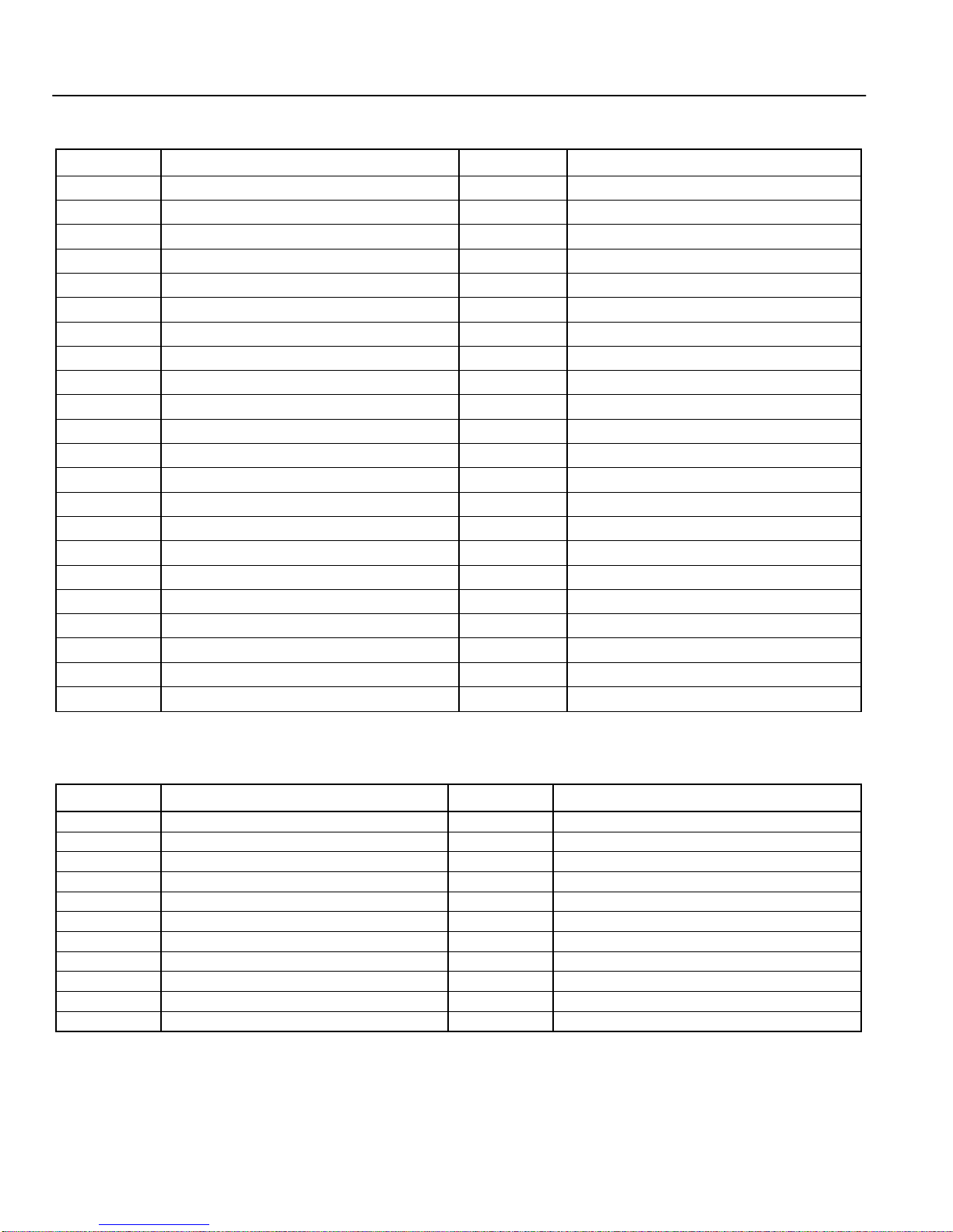
I-120
Item Number
Description
Item Number
Description
1
Casing
*71
Intermediate
2 or 3
Impeller
73
Gasket, Sleeve
*6
Shaft
*73A
Gasket, Suction Cover
*7
Wear Ring
73X
Gasket, Impeller
9 or 10
Suction Cover
89
O-Ring, Backcover
11
Backcover
*89A
O-Ring, Suction Cover
14
Shaft Sleeve
89C
O-Ring, Impeller
*16
Ball Bearing, Radial
89X
O-Ring, Shaft Sleeve
17
Gland
*90
Mechanical Seal
*18
Ball Bearing, Thrust
*131**
Coupling Guard
*19
Bearing Frame
131A**
Splash Guard, Bearing Frame/Intermediate
*22
Bearing Locknut
*180
Packing
26
Impeller Capscrew
*200
Motor
28
Impeller Washer
422 or 423
Pipe Plug, Casing
*29
Lantern Ring (For Units with Packing)
600
Capscrew – Casing/Backcover
32
Key, Impeller
601
Capscrew – Bracket/ Backcover
*35
Bearing Cap
*605
Capscrew – Intermediate/Motor
40
Slinger
*608
Socket Head Bolt – Bearing Cap
*42**
Coupling
611
Capscrew – Suction Cover/Casing
*46
Key, Coupling
615
Hex Nut - Gland
*68
Spacer - Mechanical Seal
630
Stud - Gland
*69
Bearing Lockwasher
645
Washer - Gland
Item Number
Description
Item Number
Description
2 or 3
Impeller
32
Key, Impeller
*6
Shaft
*69
Bearing Lockwasher
14
Shaft Sleeve
73
Gasket, Sleeve
*16
Ball Bearing (Radial)
73A
Gasket, Suction Cover
*17
Gland
73X
Gasket, Impeller
*18
Ball Bearing (Thrust - Impeller End)
89
O-Ring, Backcover
*89A
O-Ring, Suction Cover
89C
O-Ring, Impeller
89X
O-Ring, Shaft Sleeve
*90
Mechanical Seal
*180
Packing
* Parts are options that vary by pumping unit.
GH Pump 120 – 16.02.EN
Table 9. Parts List
* Parts are options that vary by pumping unit. ** Not shown
Table 10. Recommended Spare Parts List
28
Page 35
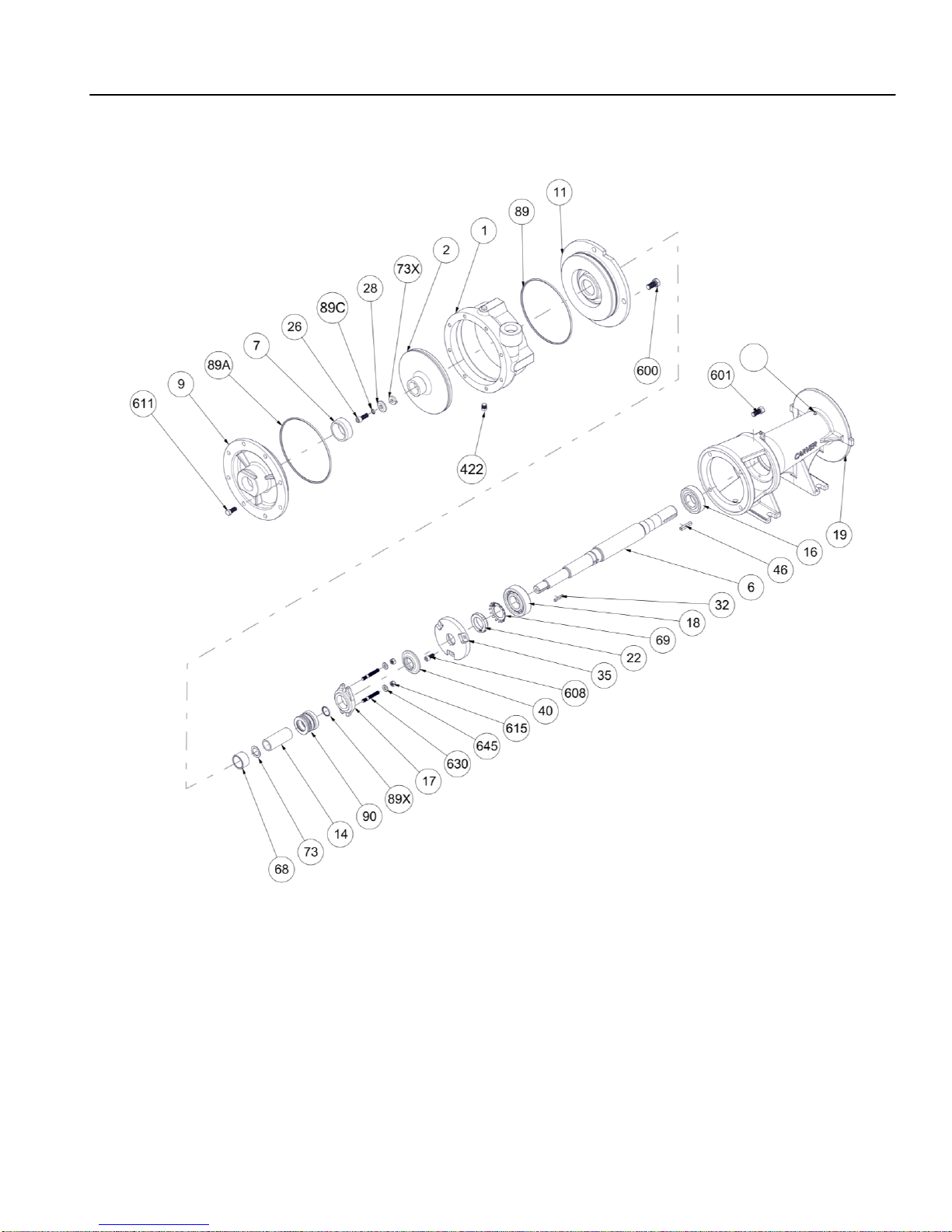
I-120
NOTE
The following items are not shown:
42 Coupling
131 Coupling Guard
131A Splash Guard, Bearing Frame
200 Motor
76
GH Pump 120 – 16.02.EN
Figure 9. Exploded View – Frame Mounted (Shown with Mechanical Seal)
29
Page 36
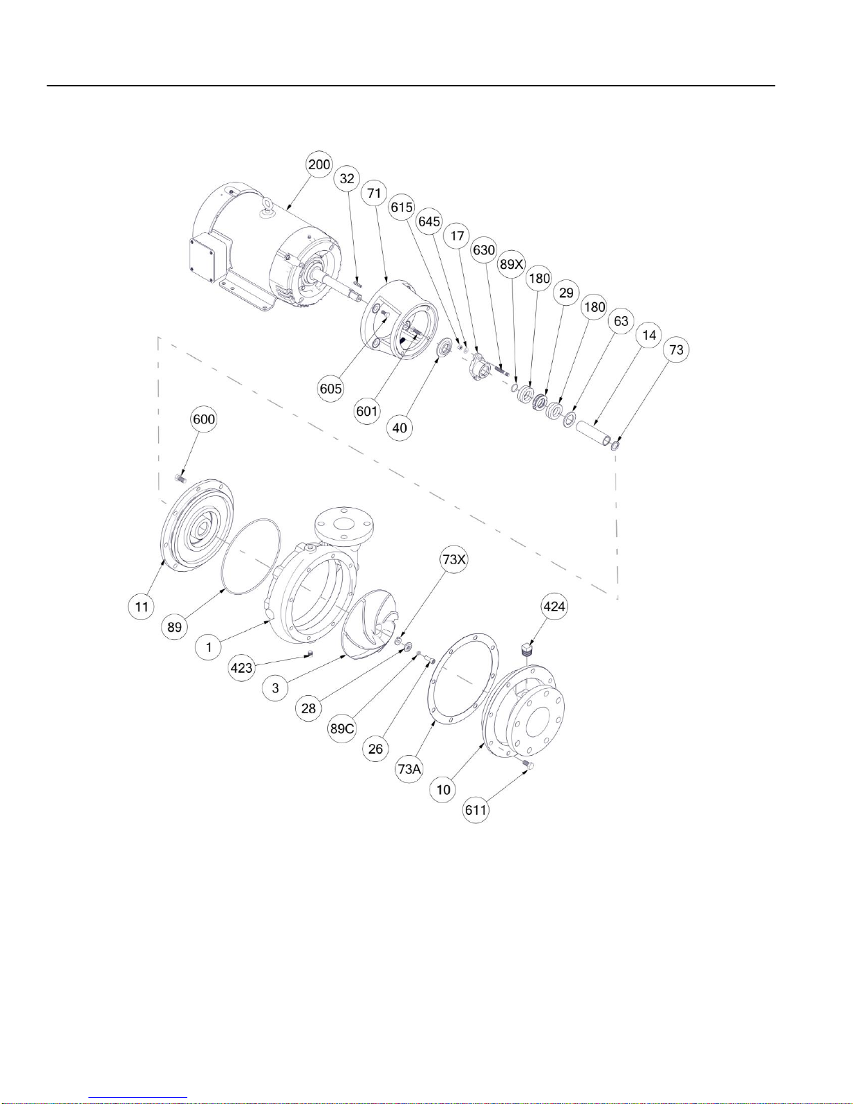
I-120
NOTE
The following item is not shown:
131A Splash Guard, Intermediate
GH Pump 120 – 16.02.EN
Figure 10. Exploded View – Close-Coupled (Shown with Packing)
30
Page 37

This page intentionally left blank.
Page 38
I-120 IOM
120 – 16.02.EN
2415 Park Avenue, Muscatine, IA 52761
Phone: 563.263.3410 www.carverpump.com
 Loading...