


CV Series Quick Operation Instructions
Mono Operation
Mono operation of the CV Series Dual Channel amplifiers can be accomplished in two ways: Parallel Mono and
Bridged Mono.
Parallel Mono is achieved by driving both channels with a single input. In the parallel mono mode, the power of
both channels can be considered as the total power, however the power is divided into two zones.
In the bridged mono mode the two channels are combined to form one mono channel of greater power. One
channel of input is fed to both channels via a circuit that inverts the input to one of the channels so that one
channel reproduces the positive half of the input waveform and the other channel reproduces the negative half of
the input waveform. In the bridged mode each channel sees one half of the total impedance. It is, therefore, not
recommended to use a bridged load below 8 ohms.
Parallel Mono – Use the Channel 2 input. In the parallel mono mode the channel 1 input is disabled.
On the input module PCB find the Bridged/Normal/Parallel mode jumpers and change it from its factory preset
“Normal” setting to the “Parallel” mono setting. (See Appendix B) By doing this you have instructed the input
module to send the channel 2 input to both channels to be used as a mono input. Both output channels of the
amplifier use a single input, and the total power of the amplifier is equal to twice the maximum output of a single
channel. However, the total power is equally divided between the two channels or zones.
Bridged Mono - Use the Channel 2 input. In the bridged mono mode the channel 1 input is disabled.
On the input module PCB find the Bridged/Normal/Parallel mode jumper and change it from its factory preset
“Normal” setting to the “Bridged” mono setting. (See Appendix B) By doing this you have instructed the input
module to invert channel one so that it now represents the negative half of the audio waveform. Channel 2 is now
the non-inverted channel and represents the positive half of the audio waveform. In this mode of operation each
channel of the amplifier see one half of the total impedance, so that, an 8 ohm load now looks like a 4 ohm load to
each channel.
To connect the speaker load to the amplifier, you would connect the positive (+) lead of the speaker load to the
appropriate terminal of channel 2 and the negative (-) lead of the speaker load to the appropriate terminal of
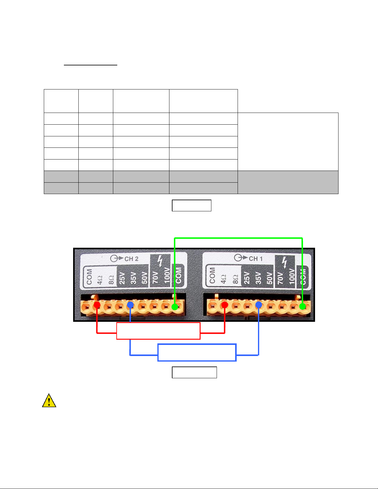
channel 1. Example: You wish to bridge the output of the CV2502 to create a Mono 70V output at 500 Watts.
Connect the positive (+) lead from the distributed load to the 35V connector on Channel 2, and connect the
negative (-) lead from the distributed load to the 35V connector of Channel 1. Be sure that the sum of the output
to each of the speakers on the distributed load is less than 500 watts. (See Figure 8) It is also necessary to
connect the commons together when bridging a distributed load.
Caution: A 4 ohm mono load should not
mode, but you can
use the parallel mono configuration with a 4 ohm load.
be connected to the CV Series amplifier in the bridged
The table below lists the recommended “Bridged Mono” connections for a CV Series Dual Channel amplifier using
Class 2 Wiring. The user should note that it is possible to bridge the 70 V and 100V terminals, however Class 1
Wiring should be observed
. All outputs will be 500 watts on the example amplifier CV2502. (See Table 2 below)
Bridged Mono Connections
(-) (+)
CH 1 CH 2 Connect to Bridged Load
4 ohm 4 ohm ------------------- 8 ohm load
8 ohm 8 ohm ------------------- 16 ohm load
25V 25V ------------------- 50V load
35V 35V ------------------- 70V load
50V 50V ------------------- 100V load
70V 70V ------------------- 140V load
100V 100V ------------------- 200V load
(+) 8 Ohm Load (-)
Table 2
(+) 70V Load (-)
Note!
Class 2 wiring Approved
Note!
Class 1 Wiring Required
Important Note: When bridging the CV Series amplifier at one of the distributed voltage outputs, it is
necessary to connect the Common connections for the distributed voltages together. The commons on the
secondary side of the output transformers are floating. This is not true for the low-impedance outputs. Their
respective commons are connected internally.
Figure 8

Appendix “B”
Input Sensitivity
Jumpers 101 and 102 on the input module’s PCB are used to set the Input Sensitivity of the amplifier for each channel or
zone. The output level of the input source determines the setting. Since, each channel or zone may have a different input
source, it is acceptable to have these jumpers set differently according to the potential output level of the input source.
The figure below show the correct jumper setting for an input sensitivity of 0.775V
Bridged, Parallel, Normal Settings
Jumper 100 on the input module’s PCB is used to configure the Standard Input Module and the amplifier in which it
resides to operate in Normal, Bridged Mono or Parallel Mono modes. It is imperative that the module be configured to the
operational mode desired before making the loudspeaker connections. Configuration of the jumpers should only be done
with the amplifier’s power OFF. The figure below shows the correct jumper placement for each of the three modes of
operation.
Bridged
Mono
Parallel
Mono Normal
JP100
CONFIGURATION
RMS
or 1.5V
RMS
.
 Loading...