

Page 1
CARVER
INSTALLATION AND SERVICING
INSTRUCTIONS
FOR
THE
3600 STC & 3600 STC AUTO CARAVAN HEATERS
LEAVE THESE INSTRUCTIONS WITH THE APPLIANCE
THIS APPLIANCE MUST
BE
INSTALLED IN ACCORDANCE WITH THE MANUFACTURERS
INSTRUCTIONS AND THE REGULATIONS
IN
FORCE AND ONLY USED IN A SUITABLY VENTILATED
LOCATION.
READ THE INSTRUCTIONS FULLY BEFORE INSTALLING
OR
USING THIS APPLIANCE.
www.vwT4camper.info - a useful website for owners and enthusiasts of VW T4 Transporter Campervans
Page 2
1.
WARNINGS AND INFORMATION
1.1 When the appliance is in use, the flue ducting becomes hot. No plastics, fabrics or aerosols must be placed
near the ducting.
1.2 This heater must be installed by a competent gas fitter working to the gas Safety (Installation and Use)
Regulations, the Health and Safety at Work Regulations, the Council for Registered Gas Installers
requirements and these fitting instructions
1.3 The heater is suitable for installation into caravans complying with B.S. 4626.
1.4 Always ensure the underfloor air intake is positioned so that it cannot blocked by mud or snow..
1 -5 Where children, the elderly or the infirm are present we recommend that when in use a guard be fitted
around the heater.
1.6 There MUST NOT be a mantlepiece or shelving sited above the heater.
1.7 Curtains MUST NOT hang within 150mm of the sides of the heater or within 300mm above the top of the
outlet grille.
1.8 Adjacent furniture or upholstery must be clear of the heater case by at least 5 millimetres.
1.9 The Carver 3600 STC & 3600 STC Auto heaters are approved to the relevant sections of B.S. 5258 part
13 1986 under the United Kingdom Accrediation Service (UKAS) and is manufactured to the quality
standard of B.S. 5750 part 2./ISO 9002.
M0 The data badge is located on the heater carcass, behind the front case.
1.11 Aerosols and highly flammable materials MUST NOT be stored in compartments behind of adjacent to the
heater.
1.12 This heater does not contain asbestos or any asbestos related products.
1.13 The gas supply to the heater must be from a regulator of adequate capacity giving a working pressure of
28mbr Butane or 37mbr Propane. Under NO circumstances should an industrial or adjustable regulator be
used on caravan applications.
1.14 The heater MUST NOT be operated while refuelling or when the vehicle is in a confined space such
as a garage, or when the vehicle is in motion or transit.
'.'5 The 3600 STC Auto ignitor is designed for connection to a 12v or 9v supply, and must not be used with
any other type of electrical supply.
1.16 The 12v gas supply must be isolated when the caravan or motor home is in transit.
1.17 When the heater is first used, it is recommended that you open a door or window and turn the tempera-
ture setting to maximum for 1 hour. This will allow any odours to escape
Note:-
If any odours persist contact your local dealer.
IMPORTANT: CORRECT POLARITY OF THE ELECTRICAL CONNECTIONS MUST BE OBSERVED OR DAMAGE TO THE ELECTRONIC COMPONENTS WILL RESULT.
2.
THE HEATER KIT - 3600 STC
The Heater kit is one Box containing:1
Heat Exchanger Assembly
1 Gas connection
1
Case with blanking bezel fitted
1 Clamp strip
1
Control rod/Piezo ignitor assembley
1 Installation box (2 parts)
4
Screws No. 8 x 30mm long (Bown) 1 Set of literature in polythene bag
4
Wood Screws No. 8 x 20mm long
6 Woodscrews No. 6 x 12mm long
The flue duct kit is one box containing:-
1
Screw (M5) - Exhaust clamp
3 Flue duct clips
1
O Ring (Red)
1 Cowl
1 Clamp ring 1 Flange head screw
1 Locking ring 1 UR Insulating duct
1
Gas connection olive
1 Length of Stainless Steel Flue duct
3600 STC AUTO
As above but with Auto ignition unit wired and pre-fitted to the heat exchanger assembly.
1.
www.vwT4camper.info - a useful website for owners and enthusiasts of VW T4 Transporter Campervans
Page 3
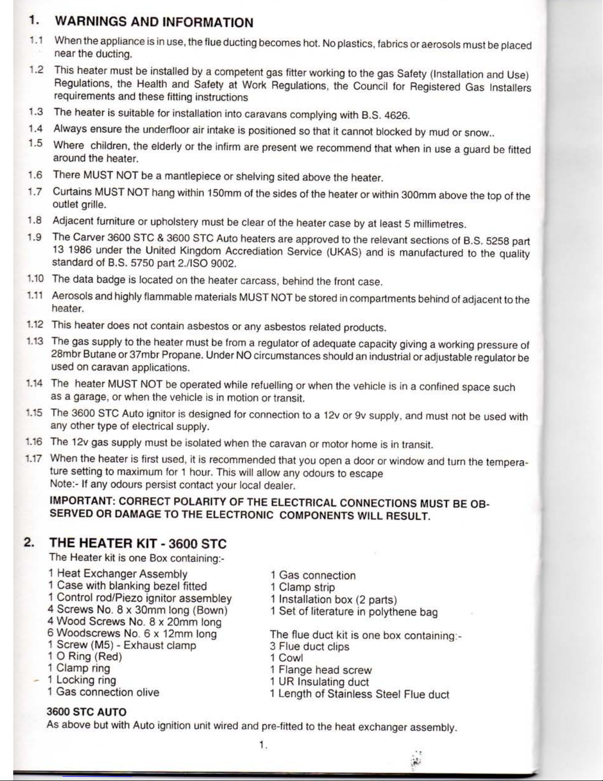
3.
CHOOSING
THE
POSITION
FOR THE
HEATER.
The heater
is
normally fitted into
the
panel
below the wardrobe door. Before commenc-
ing any fitting ensure that the appliance will
fit into the desired position (see fig.
1.).
The
installation box will be recessed into the panel
of the wardrobe
by
110mm.
4.
FITTING
THE HEATER.
4.1 TURN OFF the gas supply
at
the cylinder.
4.2 Ifpossibleliftawaythefloorcoveringfromthe
front of the panel or wall into which the heater
is
to be
fitted.
If
this
is not
possible
the
template will have
to
be positioned on top
of
the floor covering.
4.3 Fold the template upwards along the arrows
marked 'Wall Cutout' front face
RH'
and place
in position as shown in fig. 2. with the rectangular cutout
to the
right. Mark and drill
two
small holes at the front corners (A & C on the
template). Drop a nail
or
similar through
the
two holes and check below the caravan that
the area between the nails
is
free
of
obstruc-
tion.
WARDROBE DOOR
OPENING—
110
mm
I
II I M
E
E
IT)
CO
St
E
E
in
ID
480mm
(«g-1)
4.4
If any
obstruction
is
found then refold
the
template along
the
arrows marked ' Wall
cutout front face
LH '
and place
in
position
with the rectangular
cut
out
to
the left. Mark
and drill two small holes
at
the front corners
(B
& D
on template). Drop a nail
or
similar
through the two holes and check below
the
caravan that
the
area between
the
nails
is
free
of
obstruction.
NOTE:
tf the
heater
is to be
fitted
in
this
position (called "Left Hand")
the
thermostat
phial
on the Gas
Control Valve
has to be
repositioned.
See
section
4.13 for
instruc-
tions.
4.5
If an
obstruction
is
still evident,
the
heater
must
be
repositioned
in
another area
in the
vehicle.
2.
www.vwT4camper.info - a useful website for owners and enthusiasts of VW T4 Transporter Campervans
Page 4
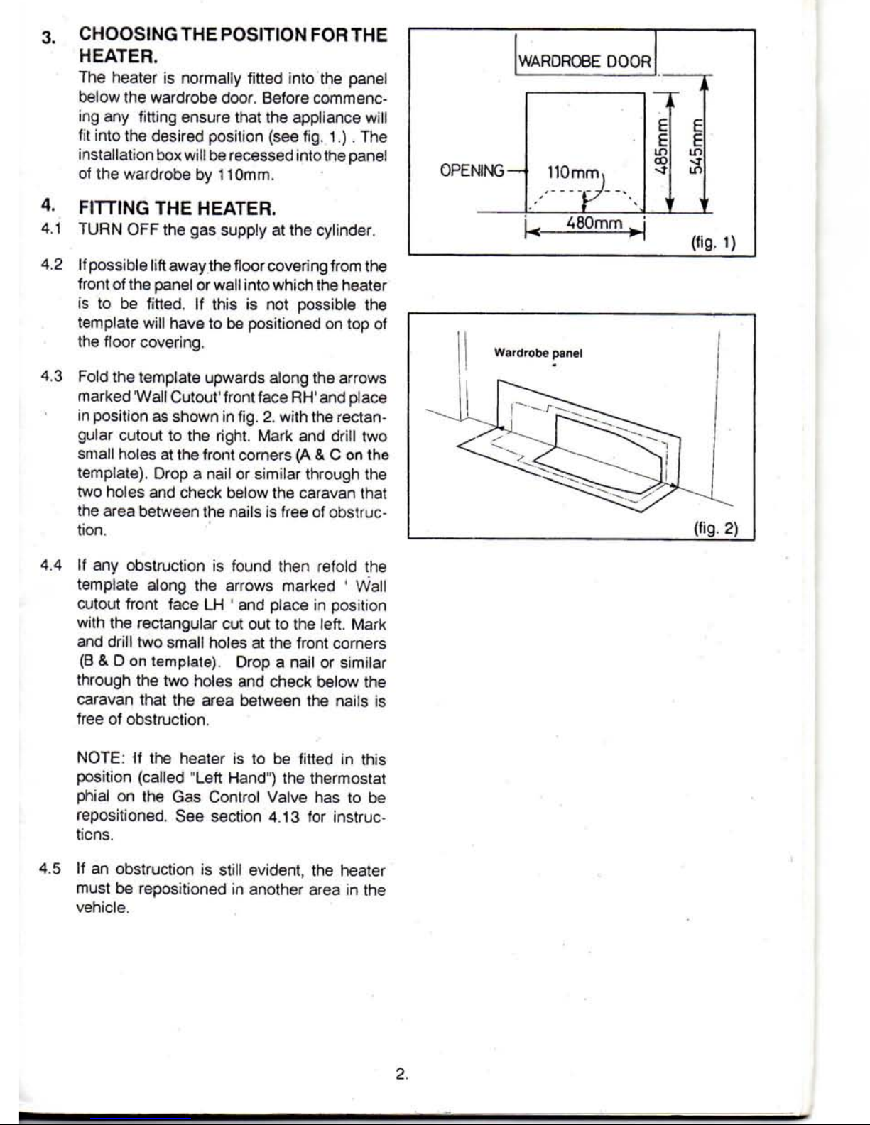
4.6 When satisfactory, mark the hole to take the
installation box. This will require a hole to be
cut in the panel 485mm high (from the floor,
below floor covering) X 480mm wide. It is
recommended that the panel surface is protected by masking tape. Score the line to be
cut with sharp knife, to stop the veneer lifting
(see fig.3) .If the panel is of the hollow type,
then the void must be filled locally along the
opening with wood.
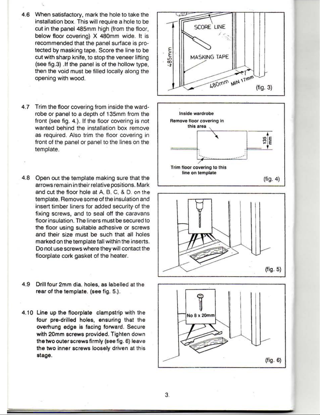
4.7 Trim the floor covering from inside the wardrobe or panel to a depth of 135mm from the
front (see fig. 4.). If the floor covering is not
wanted behind the installation box remove
as required. Also trim the floor covering in
front of the panel or panel to the lines on the
template.
4.8 Open out the template making sure that the
arrows remain in their relative positions. Mark
and cut the floor hole at A, B, C, & D. on the
template. Remove some of the insulation and
insert timber liners for added security of the
fixing screws, and to seal off the caravans
floor insulation. The liners must be secured to
the floor using suitable adhesive or screws
and their size must be such that all holes
marked on the template fall within the inserts.
Do not use screws where they will contact the
floorplate cork gasket of the heater.
4.9 Drill four 2mrn dia. holes, as labelled at the
rear of the template, (see fig. 5.).
4.10 Line up the floorplate clampstrip with the
four pre-drilled holes, ensuring that the
overhung edge is facing forward. Secure
with 20mm screws provided. Tighten down
the two outer screws firmly (see
fig.
6) leave
the two inner screws loosely driven at this
stage.
Inside wardrobe
Remove floor covering in
this area ,
\
5 1
9-
Trim floor covering to this
line on template
(fig.
4)
3.
www.vwT4camper.info - a useful website for owners and enthusiasts of VW T4 Transporter Campervans
Page 5
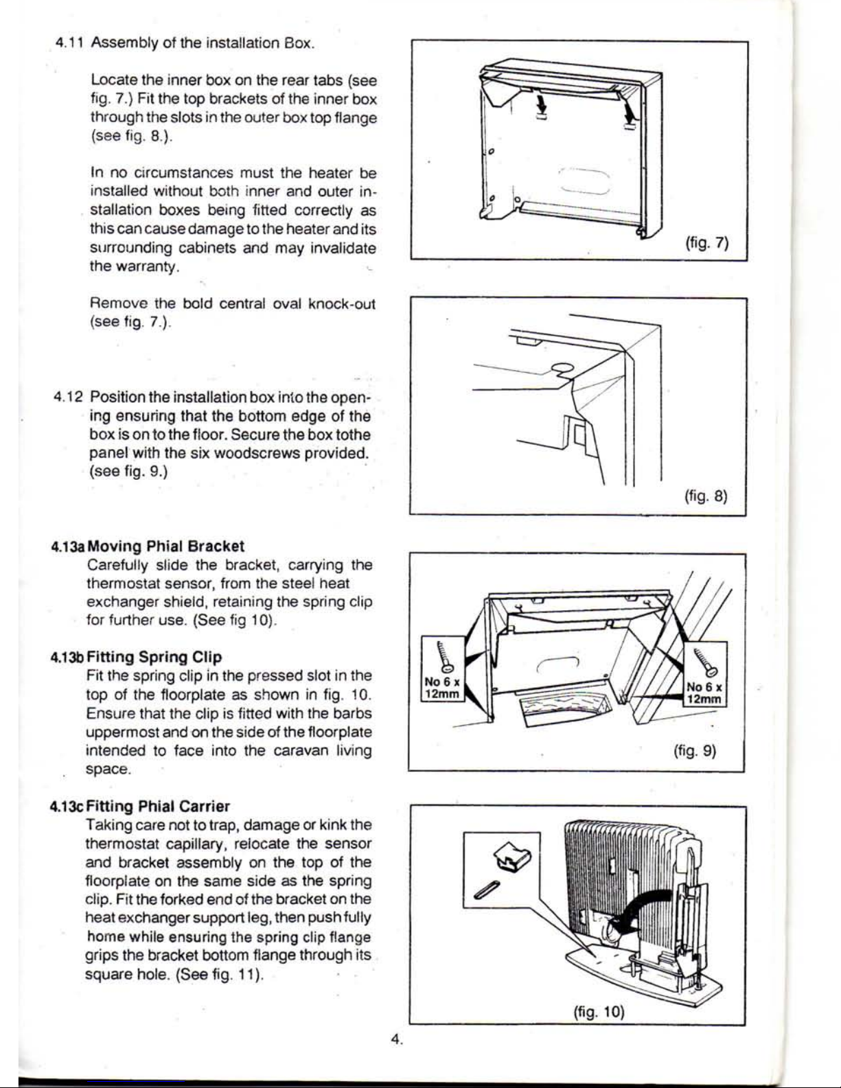
4.11 Assembly of the installation Box.
Locate the inner box on the rear tabs (see
fig.
7.) Fit the top brackets of the inner box
through the slots in the outer box top flange
(see fig. 8.).
In no circumstances must the heater be
installed without both inner and outer installation boxes being fitted correctly as
this can cause damage to the heater and its
surrounding cabinets and may invalidate
the warranty.
(fig-
7)
Remove the bold central oval knock-out
(see fig. 7.).
4.12 Position the installation box into the opening ensuring that the bottom edge of the
box is on to the floor. Secure the box tothe
panel with the six woodscrews provided,
(see fig. 9.)
4.13a Moving Phial Bracket
Carefully slide the bracket, carrying the
thermostat sensor, from the steei heat
exchanger shieid, retaining the spring clip
for further use. (See fig 10).
4.13b Fitting Spring Clip
Fit the spring clip in the pressed slot in the
top of the floorplate as shown in fig. 10.
Ensure that the clip is fitted with the barbs
uppermost and on the side of the floorplate
intended to face into the caravan living
space.
(fig.
9)
4.13c Fitting Phial Carrier
Taking care not to trap, damage or kink the
thermostat capillary, relocate the sensor
and bracket assembly on the top of the
floorplate on the same side as the spring
clip.
Fit the forked end of the bracket on the
heat exchanger support
leg,
then push fully
home while ensuring the spring clip flange
grips the bracket bottom flange through its
square hole. (See fig. 11).
www.vwT4camper.info - a useful website for owners and enthusiasts of VW T4 Transporter Campervans
Page 6

4.14 Lower the heater
into
the floor hole and
position the heater centrally in the installation
box, ensure
that
the rear edge of the
floorpiate is pushed under the fioorplate
clampstrip. (see
fig.
12 point 1.)
Check
that
the thermostat phial and its
carrier face out
into
the living
space.
On
3000 S Auto models, take care not to
damage the flying leads or terminal block,
and ensure
that
they remain above floor
level
with
the heater fitted.
4.15 Once the heater is in position use the four
brown screws provided to secure it via the
holes
in the
front
edge of the floorpiate (see
fig. 13). Drill 2 millimetre pilot holes when
screwing
into
solid wood.
4.16 Working inside the wardrobe tighten the
remaining two 20mm screws
on
the fioorplate
clampstrip.
4.17 it is important
that
all the screws are
tight-
ened
evenly to avoid distortion of the heat
exchanger
floorplate, and to ensure an air
tight
seal
to the floor.
4.18
IMPORTANT
: The floorpiate
MUST
NOT
be positioned on top of any floor covering,
as
this would prevent a satisfactory
airtight
room
seal.
FITTING
THE FLUE AND COWL.
5,
5.1
5.2
NOTE:- The
cowl
must
be
fitted
to the
roof
of the
caravan
only
and the
whole
installation
must
conform
to
BS5440
Part
1.
The centre of the cowl should be at least
80mm from the edge of the caravan. If the
caravan
has a sloping roof ensure
that
no
part of the cowl overhangs the edge of the
caravan.
The flue direction should be as
straight as possible and should rise
con-
tinually from the heatertothecowl.lt should
run against the panel to which it will be
screwed
Cut
a 60mm diameter hole in the roof at the
required position. To avoid distortion in
insulated or double roofs insert a band (1)
of aluminium of the same
width
as the gap.
Fit the cowl from the outside ensuring the
rubber
seal
(2) is in place and then, from
inside,
fit and
firmly
tighten the plastic nut
(3)
with
the screw on theside (see fig. 14).
Spring
clip
fitted
(fi9- 11)
(fig. 15
fa-13)
www.vwT4camper.info - a useful website for owners and enthusiasts of VW T4 Transporter Campervans
Page 7

5.3 Be very careful when handling the flue
duct as the edges are extremely sharp.
Bend one end of the inner flue duct sharply
to 90° as shown in fig.15.
NOTE:-
To help you fit the flue the following tools
are available from Carver Spares
Department:-
Cutting Jig Part Number R701067
(Jig to assist in cutting the flue square.)
Mandrel Part Number R701063
(To assist in the bending of the flue.)
5.4 From inside the wardrobe feed the bend
end of the inner flue duct through the knockout in the installation box. Slide the locking
ring
(1),
the clamp ring (2) and the O ring (3)
over the end of the duct end. (see fig. 16.)
5.5 Firmly push the duct into the heat exchanger
up to the
stop.
SlidetheOring, clamp ring and
locking ring up to the heat exchanger making
sure the tapped hole in the locking ring is
towards the top. Engage the ears of the
locking ring behind the projections on the
heat exchanger and rotate it so that the ears
are near horizontal. Insert and tighten the M5
screw. This will compress the 0 ring and fix
the exhaust duct to the heater. This joint is
critical for the safe operation of the
heater
(see
fig.
17.)
5.6 Lay the inner flue duct along its required
route to the outside cowl taking into account the attachment to the flue support,
(para.
5.8.) Allow 110mm for insertion into
the cowl and cut to length, erring on the
long side. Slide the insulating duct over the
flue until the lower end is inside the installation box and cut so that its upper end is
flush with the inner duct.
5.7 Push back the end of the outer duct and
firmly insert the inner duct into the cowl
right up its stop (about 110mm ). Allow the
outer duct to spring over the outside of the
cow! up to the nut. Just below the nut drill a
3mm hole through both ducts and the cowl
and fit the flange head screw through all 3
items,
(see fig. 18.)
75mm.
STRAIGHT
6.
www.vwT4camper.info - a useful website for owners and enthusiasts of VW T4 Transporter Campervans
Page 8

5.8 Inside the wardrobe fit the main flue support
bracket in a position which prevents
the flue sagging. Secure the flue to it
with
the strap provided.
Secure
the flue along its
length against the caravan structure using
all of the 3 duct clips provided, (see
fig.
19.)
It is important
that
the flue rises continually
from the heater to the cowl and
that
there
are as few bends as possible along its
length.
It is
extremely
important
that
the
flue
system
is sound and
that
it has
been
correctly
fitted
at
both
ends. The
safety
of the occupants
depend
on the
integ-
rity
of the
flue
system.
6. CONNECTION TO THE GAS SUPPLY
Ensure
that
the gas supply is turned
OFF
at
the cylinder.
Connect
the 8mm diameter caravan heater
feed pipe to the gas valve under the
cara-
van,
using
the nut and olive provided. When
tightening the valve connection, two
span-
ners MUST be
used:
one to tighten the nut
and the other, for steadying purposes, on
the
fiat
surfaces of the valve itself.
The gas pipes or valve
MUST
NOT be
placed
under any straim while
fitting
to the
heater.
NOTE : The
size
of the supply pipe
MUST
NOT
be less than 6mm (1/4 ") O.D. For
heater servicing purposes an approved
isolating valve, mounted in an accessible
position is recommended. After connect-
ing,
turn
on the gas at the cylinder and
check
the system up to the appliance gas
valve for leaks using soapy water or other
approved leak testing methods.
©
GREEN
POSITIVE
•
SUPPLY
AUTO
IGNITER
FLYING
LEADS
(fig. 21)
WHITE
NEGATIVE
SUPPLY
o
At
FIBREGLASS
SLEEVE
7
www.vwT4camper.info - a useful website for owners and enthusiasts of VW T4 Transporter Campervans
Page 9

7.
CONNECTION
TO THE 12v or 9v D.C.
SUPPLY
3600
STC AUTO
7.1
Disconnect and isolate the caravan battery
and ensure
that
the caravan circuitry
is not
connected
to
any 240v mains supply.
7.2
Pass
the
sleeved flying leads through
the
lower hole in the back of the installtion box
behind
the
control shaft support bracket.
(See
fig. 20).
7.3 The wires are coloured
in
accordance
with
the following code:
GREEN - POSITIVE
(+).
WHITE - NEGATIVE
(-V
WARNING:
CORRECT POLARITY MUST
BE'OBSERVED
WHEN
CONNECTING
TO
THE CARAVAN SUPPLY
OR
THE AUTO
IGNITION
UNIT
WILL
BE DAMAGED.
(See
fig.
21)
IMPORTANT:
THE CARAVAN SUPPLY TO
THE AUTO
IGNITION UNIT
MUST
BE
PROTECTED
BY A
FUSE
OF
MAXIMUM
RATING
OF 5A.
7.4 When satisfactory, reconnect
the
caravan
battery, again observing the correct polarity.
8.
FINAL
ASSEMBLY
8.1
First fit the control rod
assembly.
Separate the
rod
from
the plastic igniter housing
and
pass
the
rod
down through the
hole
in
the installation box
front,
ensuring
that
the foam
backed
aluminium
disc
remains sitting
on top of
the installation
box, foam side down.
Reconnect
the
rod
to the
piezo
housing.
Locate
the bottom ball
joint
overtneshaped
gas
control
rod,
and
push
securely together,
(see
fig. 22B)
3600
STC ONLY:
8.2 Firmlypushthesmaliinsulatedfemaleconnector
on the
raniter
lead
through the guide hole
and
on
to the male terminal on !he igniter
unit.
Connect
the free end of the earth lead to the tab on the
side
of the piezo igniter housing (see fig. 22)
8.3 The heater
case
has
been
factory
built
to suit
a
Right Hand installation.
For a
left
hand
installation, push
the
blanking bezel
out of
position
on
the top
panel
and
push
into
place
on
the
right
hand side (see
fig.
23)
8.4
Locate
the heater
case
overthe top
edge
of the
installation box and the control knob.
Press
in
the bottom
of
the
case
on
to
the spring clips
located
at the
bottom
of
the installation box.
(see
fig. 24).
It
will
be
useful
at
this stage,
to
check
The
operation of the
piezo
or auto igniter.
For
thepiezo,
press
the knob
firmly
downwards
several
times
and
observe a spark
at the
burner.
On
the
Auto, when
the
caravan supply
is
restored, press
the
knob down
and
turn
anticlockwise where a constant "ticking" will be
heard.
Observe the spark
at
the burner,
and
the knob illuminated indicator.
If a spark cannot
be
seen,
check the assembly
procedure in sections 7 and
8.
Before using your appliance remove
the
protective covering on the brass strip,
if
fitted.
/-
""N
Blanking
\^f~
Bezel
(fig.
23)
www.vwT4camper.info - a useful website for owners and enthusiasts of VW T4 Transporter Campervans
Page 10

9. TESTING THE HEATER •
3600
STC -
9.1 Ensure the gas is
turned
on at the cylinder.
9.2 Purge any air
from
the system by pressing
down
and turning the control knob to the ignition position (" —^ ") and firmly holding
it down, for
approximately
20 seconds.
9.3 Turn the control knob clockwise to the off ("•") position and release,
9.4
WAIT 3 MINUTES
TO CLEAR ANY RESIDUAL GAS.
9.5 Press
down
and
turn
the control knob to the " —*— " position and then press igniter firmly downwards. A click will be heard as
the
igniter
operates
to
light
the
pilot
burner.
9.6 Continue holding the gas control knob
down
whilst
checking that pilot burner is alight by observation through the viewing window.
If the
pilot
burner
does not
light
immediately,
push the igniter down repeatedly until it does light
9.7 Continue to hold the control knob
down
for 20 seconds while the flame failure protection device operates, then release the control
knob and the
pilot
burner
will
remain
alight.
To operate the main burner,
turn
the knob anti-clockwise and set at the desired position
between
high and low.
9.8 If the
burner
does not remain
alight,
repeat
operation from stage 8 3 but
always
wait 3 minutes
before
attempting
to
relight
the
heater.
9.9 To
turn
off,
return
the control knob to W position
9.10 TO ADJUST THE ROOM TEMPERATURE
Turn the Gas Control Knob to the
setting
that
gives the required comfort
level.
The main burner will
'cycle'
on and off automatically
as
required
by the
thermostat
to
maintain
to the set tern perature but the pilot flame will always remain alight
10 TESTING THE HEATER-3600 STC AUTO . _
10.1 Ensure the gas is turned on at the cylinder, and that the vehicle's 12v supply or 9v battery is correctly connected and switched on.
10.2
Turn the control knob anti-clockwise to the V»-^ " position, where the igniter will be heard to operate by an audible "ticking" noise and
the indicator will illuminate.
10.3
Press
the knob firmly downwards while the igniter contiues to operate for several seconds while air is purged from the gas supply.
Observe
that the pilot is alight through the viewing window, when the audible ticking stops and the indicator stops illuminating.
10.4 When the pilot burner lights, contiue to hold the knob for 20
seconds
whife the flame failure protection device operates, then release the
control knob and the pilot burner will remain alight.
i 10.5 Test the "Full
Flame"
fuction, by now turning the control knob further anticlockwise tio the desired position between high and low.
i 10.6 If the burner does not remain alight, repeat the operation from stage 1.
ALWAYS
WAIT
THREE
MINUTES
BEFORE
ATTEMPTING
TO
RELIGHT
THE
HEATER
To
turn
off,
return
the control knob to the "•" position.
11 TECHNICAL SPECIFICATION
HEAT
INPUT
MAX
MIN
3.75 kW
0.40 kW
HEAT
OUTPUT
MAX
3.2kW
GAS
CONSUMPTION
BUTANE
MAX
MIN
274 grams/hr
29.3
grams/hr
PROPANE
MAX
MIN
270
grams/hr
29.3
grams/hr
EFFICIENCY
MAX.
GROSS
86.0%
GAS
SUPPLY
PRESSURE
BUTANE
PROPANE
28
mbar
37
mbar
GAS
FEED
PIPE
TO
HEATER
8mm O/D
MINIMUM
SUPPLY
PIPE
SIZE
6mm O/D
IGNITION
PIEZO/AUTO
WEIGHT
12.3Kg
CARAVAN
SIZE
RECOMMENDATIONS
(UK).
7.9 metres (26 ft) March to October
6.4 metres (21 ft) All
Year
www.vwT4camper.info - a useful website for owners and enthusiasts of VW T4 Transporter Campervans
Page 11

SERVICING
INSTRUCTIONS
The
Gas Safety and Use Regulations 1990 and various British Standards lay down strict requirements for the installation and servicing of LPG appliances installed in domestic premises and mobile
homes,
such as caravans or motor vans. Carvers operate special training schemes for Dealers and
their staff to ensure
that
they understand these legal and technical requirements when working on
Carver
LPG appliances. This facility is backed up by a 24 hour on-call system operating from Carver's
HQ
at 0543 452127.
The
installer of the LPG appliance, be it at the Caravan Manufacturer's factory or at the Dealer's site
or on the Caravan site itself, carries the
first
responsibility for the correct installation according to
Regulations and these Carver Instructions but this responsibility is carried forward to any service engineer
who is required to service or repair the appliance.
If therefore, you are called to a site to service or repair the LPG heater you must ensure
that
there
have
been no adverse changes of installation or use since the time of installation or last servicing
and
complying
with
Regulations applies
just
as importantly even if the service engineer's operation is
only disconnecting and re-connecting the appliance for attention off the site.
These
requirements understandably are directed at the
SAFE
and
EFFICIENT
use of the heater.
There
are no short cuts to safety and you are reminded
that
you must be properly trained before you
work on LPG appliances,
The
Carver 3600 STC and 3600 STC Auto are reliable well tried appliance and should give years of
satisfactory and trouble free use but like all gas appliances, they need servicing on a routine schedule.
The
following schedule covers work on the appliances, both in the caravan and when removed from
the caravan for attention in the workshop. These are the main headings of the schedule but other
work may be required depending on the circumstances at the time of dealing
with
the heater.
(i) When serviced in the caravan
Itself
and normally working
(1) Check
that
the appliance is being used correctly, i.e. ther are no
fire
risks through proximity
to shelves and clothing.
(2) Check
that
the air inlet and flue
outlet
are not blocked in any way and are in the correct position
on the van; (refer to BS5440 Part 2 for guidance)
(3) Check the systems for gas tightness;
(4) Check the flue system for soundness during operation.
(5) Check
that
the heater has been installed correctly. Refer to these Installation Instructions especially
on the need for proper clearances around the heater,
(6) Check
that
the gas supply system is correctly installed and working;
(7) Check
that
there are no dangerous hot spots on the heater when in operation; indicated by
burnt
areas
of decorative paintwork;
(8) Check
that
the controls operate smoothly and correctly and
that
the flame failure system works
correctly;
(9) Check the flame structure on the burner itself and see
that
the ignition system works satisfactorily;
(10) Now remove the
case
from the heater, replace any faulty components, clean away all extraneous
dust, check the operation of all components and safety devices;
(11) Check the gas tightness of the installation at the end of the servicing schedule;
(12) Confirm
that
the user understands the operation of the heater.
(13) Ensure
that
the flue terminal plastic nut (fig. 14) is fully tightened inside the caravan.
(ii) When the appliance is serviced
away
from
the caravan
Servicing
the appliance itself in a separate workshop will require, where appropriate, attention to items
2-10 above.
(iii) Fault
diagnosis
When
called in to diagnose and repair any working
fault,
even a simple correction will still require
you to carry out the standard servicing schedule in
case
one detectable
fault
has cloaked other poten
tial faults.
We
have included here a
fault
diagnostic chart to help you to trace faults in the ignition system.
10.
www.vwT4camper.info - a useful website for owners and enthusiasts of VW T4 Transporter Campervans
Page 12

FAULT
FINDING
Turn the control knob to pilot / ignition, positionand
press
firmly
down
Heater
Lights
I
YES
NO_
.Can
a spark be seen through the window onto the
top of the burner?
YES
I
Is gas supply and
isolating taps on?
YES
NO
Purge
system Turn on gas supply
and/or isolating taps,
check
cylinder is not empty.
NO
Check
Piezo
ignitor
or auto ignitor and .
9v or 12v supply yEg
Is there a spark to the top of
I the burner?
NO
I .
Replace
_
component
Is burner to electrode
position correct? i.e. 3 to 4mm spark gap
YES
NO.
Relocate
Are
leads satisfactory? i.e. any damage to the wire
I insulation
YES
NO
Continue
to hold the control knob down for a
minimum of
twenty
seconds.
On release of the
knob does the flame continue to burn?
Replace
-component -
I
YES
NO
I
Wait 3 minutes and relight. Hold the control knob
fully down for 30
seconds.
Does
the flame continue to burn?
YES
THE
IGNITION
SYSTEM
IS OPERATING
SATISFACTORILY. TURN
CONTROL KNOB TO
REQUIRED SETTING.
NO
Is the thermocouple screw
tight
into
the bottom of
the control?
I 1
YES
I
Is the thermocouple tip
in the burner flame?
NO
Screw to finger
tight
plus
t/4
turn
—
YES
I
NO..
.Adjust-
Is the thermocouple satisfactory?
r
YES
NO
Replace.
component
Replace
gas
' control valve"
11,
www.vwT4camper.info - a useful website for owners and enthusiasts of VW T4 Transporter Campervans
Page 13

CARVER
SERVICE:
01543
452122
If
you experience difficulties
with
any
Carver
product, please contact the dealer
from
whom
it
was
purchased,
or if
this
is
not
possible
any
Carver
MAIN
DEALER
listed below. A Main dealer will also undertake
warranty work
on all
Carver
products,
regardless
of
where
they were
purchased.
Carver
& Co.
(Engineers)
Ltd.
now
provide
three
levels
of
dealership
to
maintain
and
repair
your
appliances.
Carver
recommend that
you
should
have your
Carver
products checked annually
to
ensure
trouble
free
caravanning.
PREMIER
DEALER - Premier Dealers
have
trained staff to service
Carver
products
on any
make
or type of
caravan and
carry
a comprehensive
range
of
Carver
products.
STANDARD
DEALER - Standard Dealers
have
trained staff to service
Carver
products on
any
caravan for
which
they
have
sold
or
any
model
of
caravan sold under their franchise and
carry a
range
of
Carver
products.
SERVICE
DEALER - Service Dealers
have
trained staff to service
Carver
products
on any
make
or type of
caravan.
PREMIER
Avon
County Caravans
Sndgwataf
Road,
Bedminster
Down.
Bristol,
Avon
BS 13 8AE
Tei 01179
642030
Fax: 01179
780309
Avon
Leisure
HartdWa Way.
Bristol,
Avon
BS3 5RU
T* 01179
667511
Fax: 01179
636451
Chicping
Sodbury Caravans
Badminton
Road
Chipping
Sodbury, Nr
Bristol,
Avon
BS17 6LH
Tel:
01454 318374
Fax
01454 324751
Davan Caravans LW
St
Georges. Weston Super Mare,
Avon
BS22
OXF
Tel:
01934 510606
Fax:
01934 516025
Mendp
Caravan Centre
Hewish
Filling
Stabon, Hewish,
Weston Super Mare,
Avon
BS24
6RT
T«t
01934 832094
Fax:
01934 876633
STANDARD
Kings
wood Caravans
1377145
High Street, Kingswood,
Bristol.
Avon
B515 4AG
Tel: 01179
600205
Fax: 01179
618605
PREMIER
Luton Caravan Centre
107
VWngate
Road,
Luton, Bedfordshire
LU4 SPZT
Tel:
01582 490079
Fax:
01582 504807
PREMIER
Berkshire
Caravans
56A
Church Lane,
Three
Mile
Cross.
Reading.
Berkshire RG6 2DU
Tel:
01734 882950
Fax:
01734 884969
Cokm
Caravans
(Berts)
Bath
Road.
Aidermaston,
Nr Reading, Series RG7 SJD
Tei:
01734 712424
f*x:
01734 713010
STANDARD
Berkshire
Motor Caravans
Oxford
Road,
Chieveley,
Newbury
&erksrweRG16
8RU
Tel:
01635 243883
Fax:
0163S 247044
STANDARD
Country Caravans
Park
Street, Aylesbury,
Bucks
HP20
1BX
TeJ:
01296 27777
Fax:
01296 27798
White Arches Caravans
168
High Street Stoney Stratford,
Milton
Keynes, Bucks MK11 1AW
Tel;
01908 563245
Fax:
01908 561817
SERVICE
The Caravan Company
Unit
1, Lower End, Waverdon,
Milton
Keynes MK17 SAP
Tel:
01908 586000
PREMIER
Courtesy Caravans Ltd.
The Drift, Elswonh, Cambridge,
Cambs
C83 8JN
Tel:
01954 267280 / 01945 267525
Fax:
01945 267662
Deeping
Caravans
Spafding
Road,
Deeping St. James.
Peterborough, Cambs
Tel:
01773 344845
Ireland Trailers
Weasenham Lane, Wisbech,
Cambwoeshire
P£l3
2RN
Tel.
01945
63161 Fax
01945 589170
Pioneer
Caravans Ltd
Thomey
Road Eye, Peterborough
Cambs.
PE6
706
Tei:
01733 222244/ 222263
Fax:
01733 222004
St
Ives
Caravans
Wigcm
HiW,
Old Ramsey
Road,
Stives,
Cambs. PE17 4LL
Tel:
01480 300621
St
Neots Cator Gas
Arlington
Road,
Eynesbury,
St.
Neots, Huntingdon, Cambs PE19 26U
Tel:
01480 213007
Weland Hobday Hire &
Sales
PosUand
Road.
Crowland, Peterborough,
Cambs
PE6 OJ'B
Tel:
01733 210560
Fax:
01733 211316
PREMTER
Caravan Court
New Piatt Lane, Goostry,
Holmes
Chapel.
Cheshire CW4 8NN
Tel:
01477 535608
D.B Caravans
365
Warrington
Road,
Cufcheth,
Nr Warrington, Cheshire WA3 5JQ
Harringtons (Cheshire)
Chester
Road,
Detamefe
Nr Northwch Cheshire CW8 2HE
Tel:
016O6 882032
Fax.
01606 889213
North Western Caravans
Earl
Road,
Cheadle Hulme, Cheshire,
3K86QE
Tel: 0161 486
6055
Fax: 0161 486
6755
Spinney Motor Caravans
Cherford
Road,
Oilefton, XnuBford,
Chesh.reWAl6 8SB
Tel:
01565 624011
Fax:
01565 650228
STANDARD
Caravan Care & Repatr
78
Ford Lane, Crewe,
Cheshire CW1 3EH
Tel:
01477 535808
Leisure Sates ltd
Brerefon Green, Sandbach.
Cheshire CWi 1 9BD
Tel:
01477 535264
Fax:
01477 53S528
SERVICE
Widnes Caravan Centre
8
Croft Street Widnes,
Cheshire WA$ 0NG
Tel: 0151 424
3378
PREMIER
West Hartlepool Leisure Ltd
13
Park View Ind. Est. Brand*
Road,
Hartepooi,
Cleveland
fS25
1PE
Tel:
01429 369811
Fax:
01429 273896
STANDARD
Hadrians
Caravans
Rrverside Estate.
Thomaby
Place,
Thornaby,
Stockton, Cleveland
TS17
6BN
Tel:
01642 679527
PREMIER
Caraleisure
Cornwall
Scorrier
Redruh Cornwall TR16 5EG
Tel
01209 820451
Fax;
01209 820116
Coach
Craft & Leisure
Unit
2 Hillside Industrial Park.
Scorrier, Redruth, Cornwall
TR16 5AW
Tel:
01209 314065
Fax:
01209 314065
Mobile
0831
670753
Mount
Caravans Ltd.
Daniels
Lane. Holmbush. St Austell,
Cornwall
PL25
3LH
Tei:
01726 75056
Fax:
01726 67443
STANDARD
S.S.Gas
Gaitows Park, Milbrook. Totpoint
Cornwall PL
11
3AX
Tel:
01752 822523
Tencreek
Caravans
Tencreek
Caravan Park, West Looe,
Cornwall PL13 2JR
Tel:
01503 262447
SERVICE
Caravan Services
Umt 8C Kingston industrial Estate,
Buas
Cornwall EX23 8QN
T«0'283
354268
Dave Barron Caravans Ltd. Barron's Great
Outdoors Burtree Gate (A68), Oariington,
Co
Durham DL2 2X2
Tei
01325 467451
Fax:
01325 464B5Q
STANDARD
Robsons
o( Wokingham
Durham
Road,
Wofsingharri
Bishop
Auckland, Co. Durham DL13 3HU
Tel:
01368 527242
Fax
01388 526494
PR
BflER
Bardsea
Leisure Park
Priory
Road.
Urverston, Cumfyia
LA1Z9QE
Tel:
01229 584712
Fax.
01229 580413
Carliste
Caravans Centre
Harker, Nr
Carlisle,
Cumbria
CAS 4DS
Tel
01228 745704
Fax:
01223 745704
STANDARD
fettoew Caravans
Beckermet.
Cumbria CA21 2XB
Sewetts Caravan Centre Ltd
High Hesket. Nr
Carlisle.
Cumbria
CA4 OJN
Tel:
01697 473407
Fax:
01697 473407
PREMKR
Autocraft Motor Caravans
Speedwell
industnal Estate.
Fan
Road,
Sraveley, Chesterfield,
Derbyshire S43 3PT
Tel
01246 471199
Fax:
01246 471199
d'ookside
Caravans
J Wan Street Breedon On The HiS,
3*by Derbyshire DE7 1AN
rel 61332 862623
Fax:
01332 862623
Coon
Caravan Services
Katam
Ftetdi RoaoV Ilkeston.
Derby,
Derbyshire OE7 4A2
1«
01159
309322
Fax: 01159
309322
Derm Hanley & Co Ltd
IM10.
Ptot6Eaoje
Road,
Quarry
Hill
Ind. Estate, Ilkeston.
Derbyshire DE7 4DA
Tei 01159
440710
Derby Caravan & Leis Ceifie
998
London
Road,
ASvastco,
Derby,
Derbyshire DE24 8QA
Tel
61332 572207
Fax:
01332 757089
Don Amott Caravans Ltd
Tei:
61283 732193
Fax:
01233 734540
Glossop
Caravans
Mam
57, Brookfteid, Giossop,
Derbyshire SKI3 9JE
Tel:
01457 863011/365215
Goodats
Caravans
Nottingham
Road,
Spondon,
Derby,
Derbyshire
Tel
61332 683191
Rooinson
Caravans
Rmgwood
Road,
Bnmington,
Chesterfield.
Derbys S43 IDG
Tel
01246 230006
Fax:
01246 204204
STANDARD
JI R Camping
Hilton,
Derby.
Derbyshire DE65 5EJ
Tel:
01283 733525
Fax:
01283 734812
PREMIER
Ashbum Caravans LH
crxiey
Road,
Asnourton, Devon
Tel:
01364 652377
Fax'
01364 652961
Caracamp
53
Union Street, Plymrxtfi.
Devon PL1 3LU
Tel:
01752 664695
Compass
Caravans
Higher Brocks Plantation. Teigngrace.
Newton Abbot. Devon TQ12 9QZ
Tei:
01626 832792
Martins
Caravan Co
39/43
Pinnrnll. Exeter Devon 6X1 3TH
Tei:
01392 466211
Fa*:
01392 466544
Mullacott
Caravan Centre
MuHacott
Cross, trfiacombe,
Devon EX34 8NB
Tel: 01271
862212
Pathfinder
Park Homes Ltd
Pathfinder
village,
Tedbum
St Mary
•
" nTx6
6r-'
By C
Guiworlhy,
Tavrstrxk.
Devon PL
19
8JE
Tel.
01622 832357
Fax:
01822 834174
Plymoufc Motor Caravans
Lee HiU.
Ivybrktoe,
Plymouth.
Devon PL21 9 EE
Tel:
01752 892977
Fax:
01752 691230
PREMIER
Caravan & Camping Shop
13
Mario*
Drive, St. Catherines
Hill.
Christchurch,
Dorset
TaT
01202 487347
Hargold Leisure
Prestonstar Ltd.
Great Western Ind. Centre. West Stabon
•Yard, Dorchester, Dorset DT1 ISA
Tel:
01305 269400
Fax:
01305 260751
Dorset Leisure Centre
Newtands Bridge, Chamxxjth,
Dorset DT6 602
Tel:
01297 560473
Weymouth
Caravan Centre
Humphries Garden Centre, Litttemoor Road
Preston,
Nr.
Weymouth
Dorset DT3 6AD
Tar,
01305 834518
Wimbome Caravans Ltd
Lakegatos,
Dorchester
Road,
Wimbourne,
Dorset BH21 3HA
Tel:
01202 838601
Fax:
01202 842808
STANDARD
8lackmore
Vale Leisure
Sherbourne Causeway. Shaftesbury,
Dorset SP7 9PX
Tel:
01747 857497
PREMIER
Homestead Caravan* Ltd.
Thorpe
Road,
Weeiey. Essex C016 9JN
Tel:
0125 5 830671
Fax:
01255 831406
Essex Motor Caravan Genre
Dunmow
Road,
Taketay,
Essex
CM22
6SJ
Tel:
01279 870755
Fax:
01279 870041
Valley Farm Camping Ltd
Valley
Road,
Clacton on Sea.
Essex C015 6LY
Tel:
01255 424422
Fax:
01255 422484
STANDARD
Cross
County
Maiden
Road,
Hatfield Peverel,
Chelmsford,
Essex CM3 2JP
Tel:
0124S 330605
Fax:
01245 330956
Global
Caravan Centre
Roydon
Mill
Caravan Park, Roydon,
Nr Harlow Essex CM19 5EJ
Tel:
01279 792777
Fax:01279
792695
www.vwT4camper.info - a useful website for owners and enthusiasts of VW T4 Transporter Campervans
Page 14

UpmnsSer
Caravans
Ltd
A13 New
Road,
Rainham,
Ejiei RM13
9E-B
Tel:
01708
(65611
SERVICE
A K.
Leuue Salts
CO
Daneb
Farm.
Wash
Road,
Baiiidon,
E»se>SS15«AZ
Tel:
0126!
53061S
fax: 01268 530615
GLOUCESTERSHIRE
PREMER
Cross
Country
A38 Roundabout. BmW Road
Gloucester.
Glos
GL2
6ES
Tel:
01452 529237
Fax:
01452 307226
Forrest of Dean Caravans
Park
End.
Lydney,
Glos
GL15
4JN
Tel:
01594 562206
Fax:
01594 563363
Golden
Castle Caravans
Stratford
Bridge,
Nr
Tewkesbury
Gloucestershire GL20 6HE
Tel:
01684
592201
Fax:
01684
594691
Golden
CasDe
Caravans
Staverton
Airport, Cheltenham
Road
East
Gtooocester, Gloucestershire GL2 SQL
Tel:
01452
713311
Fax:
01452 856538
Mclntyre
Caravans
Hempstead Bridge.
312-318
Bristol Road,
Giooucestor.
Gloucestershire GL2
60H
Tel:
01452 410710
Fax:
01452 309970
Pear
man
Briggs
Leis.
Ltd.
224
Cheltenham Road, Gloucester,
Glos
GL2
0JW
Tel
01452
524700524192
Fan:
01452
309679
PREMIER
Tumm Motor Caravan Centre
11A Barry
Road.
London
SE22
0HZ
Ttt 018f
693 1132
GREATER
MANCHESTER
PREMIER
Jacks
Bros.
Caravan Centre
53
Manchester
Road,
Clifton,
Swintan, Gtr
Manchester, M27
8W2
Tel:
0161 793
6000
Fax:
0161 794
6360
Progress
Caravans
1050
Manchester Road, Castleton,
Rochdale,
Lancashire OL11
2XJ
Tel:
01706 44095
Fax:
01706 661727
PREMfcR
Chichester
Caravans
Main
Road,
CoWen
Common,
Ni Winchester. Hampshire $021
1TO
Tel:
01962 714844
Fax:
01962 714913
Green Pennant Caravans
West
End
Road, Bixserdon, Southampton.
Hampshire
SOS
8BP
Tel:
01703 405122
Fax:
01703 402599
Hampshire Caravans
'Winchester Road,
Popham.
Winchester,
Hampshire S021
381
Tet:
01256 397304
Fax:
01256 398179
Hants & Dorset
Caravans.
London
Road,
Purbrook, Portsmouth. Hampshire
Tel:
01705
374921
Fax:
01705 201085
Krueger Limited
Ltnil
16,
Oueensway,
Stem
Lane
Ind. Est.
New
Milton,
Hampshire BH25
SNN
Tel:
01425 619869
Fax:
01425 638640
South
Of England Caravans
51
Portsmouth Road, Lohook
Hampshire GU30 7EE
Tel:
01428 724160
Fax:
01428 723528
STANDARD
Fleet Caravans
Ltd
Grange Estate.
Church
Crcokham.
Fleet,
Hampshire
GUIS
OCR
T«f:
01252 614000
Greenford Caravan Co.
Brtckhose Hill, Fleet
Road,
Eversley,
Basingstoke,
Hampshire RG27
QPY
Tet
01734 328326
Leisure Fayre
36 High
Street,
Lyndhurst
Hampshire
S043
7BG
Tel:
01703 283445
Viscount
Caravans,
Swan
Garden
Centre.
Mambndge
Road,
West
End,
Southampton. Hampshire S03 3HW
Tel:
01703 466918
SERVICE
Avonbridge Repair Service
The OUTondry, Stockton, Fordngbndge
Hampshire
SP6
2HG
Tel
01425 654353
Marquis Service Centre
Winchester
Road.
Lower Upham
Southhampton. Hampshire S63 1HA
Tel:
01480 860660
Fax:
01489 860825
Springfield Leisure
48
Longmore
Road,
Liphook.
Hampshire GU30 7NY.
Tel:
01428 724398
Fax:
01428 724396
Mobile: 0831
306057
HEREFORD*.
WORCS
Cross"
Country
(Bromtgrove)
Worcester Road, Upton Warren.
Sromsqrove.
Worcs B61 7EX
Tel:
0J327
831515
Fax:
01527
575171
Chichester
(Stourport)
Vale
Road.
Stourport
on
Severn,
Worcs
DY13 8YJ
Tet:
01299
625221
Fax:
01299 827385
Hereford Caravan Centre
Holmer
Road,
Hereford, HR4 9RX
Tel:
01432 269476
Tax:
01432 356117
WyesKJe
Caravans Ltd.
Bishops
Wood, Ross-On-Wye,
Herefordshire HR9 5GX
Tel:
01594 860303
Fax:
01594 860342
PREMIER
Herts & North
London
Caravans
Bremners Garage,
(A1000),
Hatfield,
Hertfordshire AL9 5SD
Tel:
01707 262875
Fax:
01707 270824
Hitchin Caravan Centre
CO
Harkness
Rose
Gardens,
Cambridge
Road.
Hitchin.
Herts
SG14 0JT
Tel:
01462 452856
Fax:
01462 422518
STANDARD
Bowers Motor
Co
(Harpenden)
Greenlawns, Kingsbourne Green.
Haipenden,
Herts
AL5
3FN
Tel:
01582 761567
Fax:
01582 462863
SERVICE
M.G Caravan Service Centre
Unit
16
Hertford
Ind. Est Gaxton Hill,
Hertford,
Herts
SG13
7NF
Tel/Fax:
01992 504990
Mobile:
0831
666761
PREMIER
SpringfkekJ Caravans Ltd.
Market
Place Hornsea,
Humbers*de HU18 1DF
Tel:
01964 532253
Fax:
01964 535530
T.C.
Caravan Repairs
Caravan Centre, Brouofi Road, South
Cave,
Humberside HU15 2DB
Tel:
01430
423950
Fax:
01430
421546
Vatfree
Caravan Repairs
Swinemoor Lane, Stepney Compount,
Beverley, HumbersirJe HU17 0JS
Tel:
01482 872066
Fax:
01482 870089
STANDARD
Danfast Ind S Leisure
English
Street,
Hiil,
Humbewde
HU3202
TeT
01482 24052
Fax.
01482
20S29
Waudb/s Caravan Centre
Brough
Road,
South
Cave,
Hull.
Humberside HU15 2DB
Tel:
0143O
422523
Fax:
01430 421548
PREMIER
Arthur FIB Caravans
Sweechbndge Road, Hittborough.
Nr
Herne
Bay,
XentCT6 6TE
Tel:
01227 373848
Fax:
01227
740901
Lee
Oavey
Group
Ltd.
Maidstone Division, East
Street.
HameSham. KentMEl7
1HN
Tel:
01622
859301
Fax 01622 659618
Milestone Caravans
32/34
Cantobury Road, Hawkings.
Nr
Folkstone,
Kent
CT18
7BP
Tel:
01303 892869
Fax:
01303 891037
Orpington Caravan Centre
Greer
Street
Gfeen.
Orpington,
Kenl
BR6 7LR
Tel:
01689
855661
Fax:
01689 850794
Songhurst, (Leisure Shop)
242 london
Road,
West
Mailing,
Kent
ME19 5AU
Tel
01732
8453M
Fax:
01732 644537
VAS
(Kent)
Ltd
Vauxtia!)
Place,
Lowfwkl
Street
Oartford.
Kent
Tel:
01322 222835
Fax:
01322 288352
STANDARD
Bromley Motor Caravans
55/65
Abbey Road, Belvedere,
Kent
DA
17 5DG
Tel:
0181 311 3500
Fax:
OtSl 311
2607
Camping
International
Clock
Tower House,
Waiting
SBeet,
Gtllingham. KentME7 1VX
Tel:
01634 577326
Fax:
01634 280155
Cross
Country BR
London
Roao, Sittngbourne.
Kent
ME
10
1CA
Tel:
01795 472185
Fax:
01795
425271
Kent
Camping
Holidays
3941
High
Stojet,
Chatham.
Kent
ME4
4EN
Tel:
01634 845152
Fax
01634 831135
PREMCR
Buriingham Caravans Ltd.
By^Pass
Road
A6,
Cabus,
Garstang. Lanes
Tel:
01995 602145
Fax:
01995
601429
Campbells Caravans
Lancashire Enterprise Business Park,
55
County
Close.
Leytand.
Lanes
PR51TZ
Tet:
01772 627627
Campbells Caravans Ltd.
Watfcin
Lane,
Lostock Hat), Preston,
Lanes
PR5
5RD
Tel
0177 2 627627
Fax.
01772 627720
Dave Baton
Chapel
Lane.
Coppull.
Chortey.
Lanes
PR7
4NB
Tet
01257 793377
Fax:
01257 793925
Harringtons Caravans
Whitebfrk
Ohve. Blackburn,
Lanes
BB1
3HS
Tel:
01254 54222
Fax:
01254 679336
Harringtons Caravans
Service Centre, Greenbank
Business
Park.
Blackburn,
Lancashire
BB1
13A
Tel:
01254 690600
Fax:
01254 605383
Leisure Accessories
T/A
The
Leisure
Shop,
C/O
Dave Barron
Caravans Ltd., ChappeH Lane. Coppull,
Chortev. Lancashire PR7 4NB
Tel:
0f257 793377
M. G Caravan
Co.
Ltd
Burnley Road, Todmorden.
Lanes
OL14 7DJ
Tel:
01706 812832
Fax:
01706 818320
Preston Car3van Centre
Croston
Road.
Lostock Hall, Preston,
Lanes
PR5
5JY
Tel:
01772 35093
Fax:
01772 324223
Stewart
Longton Caravans
North
West
Caravans,
70 Siyne Road.
Bolton-le-Sand.
Camforth,
Lanes
LAS SAL
TeS:
01524 822270
Fax:
01542 824273
Friday
Street,
Off Slump Lane Chorley,
Lanes
PR6
0AH
Tel:
01257
279921
Fax:
01257 241877
Todds
Mobile Leisure Ltd.
Coote Lane. Lostock Hall, Preston,
Lanes
PR5
5HS
Tel:
01772 35360
Fax:
01772 627853
W. 4 A.
Hartley
Ltd.
Blackpool
Road, Kirkham, Nr Preston,
Lanes
PR4 2RE
Tel:
01772 683868/685592
Fax
01772 671840
Whitford
Caravan Centre
Maribcrough
Street.
Healeywood
Ind. Est
Burnley, Lanes BB11
2HP
Tet
01282
420029
Fax:
01282 454610
STANDARD
Callenoer Caravans
Ltd
Scotland Road, Carnforth,
Lanes
LA5
9RF
Tel
01524 732224
Fax.
01524 732226
Caravan Care Services
Marlon
Mere
Caravan
P*k
Mythop Road, Marfan, Blackpool.
Lancashire FY4
4XN
Tel:
01253 765783 Fax 01253
839111
Caravans Services
Melting
Sockbum
House, Melting,
Carnforth,
Lanes
LAS
2QY
Emm-Bee Caravans
(Fleetorace)
Limited.
Prettywood
Bury,
Lanes
BL9
7HX
Tel:
0161 797 2986
Shipleys
(Ashton-u-Lyne)
Roaches
Lock. Manchester Road.
Mosstey.
Lanes
OL5
9BL
Ttt
01457 835553
Fax:
01457 835790
Stewart
Longton
(Standish)
A49 Preston
Road,
Standish, Nr Wigan,
Lanes
WN6 0JH
Tel:
01257
279921
Fax:
012574 41877
Stewart
Longton (Blackpool)
228
Common
Edge
Road,
Marton
Blackpool.
Lanes FY4
5DH
Tel:
01253 763133
Fax-
01253 798106
SERVICE
Crossfey
Coaehcraft
Unit
33A
Comet
Road,
Moss
Side
Ind. Est.
.ancashire PR5 3QN
2
623423
Fax:
01162 610707
PREMIER
The Caravan Shop
St
Margaret's
Way, Leicester. LE4
OBT
Tel:
01162 536767
Fax:
01162 530222
Caravans Services
Leics.
17
Abbey
Court
Waflinaford
Road,
Leicester.
Lacs
LE4
5RD
Tel:
01162 668948
Fax:
01162 610707
Leicester Caravan & Leisure
50
Oswin
Road,
Bradford Ind Park.
Off
Hinkkty
Road
Nr Wester Park,
Leicester. Lees
L£3
1HR
Tel:
01162 470740
Fa*:
01162 470865
Pnory Caravan Centre
Ashby
Road
Central, Shepshed.
Nr ^ou^borough.
Letcs
IE
12 9EF
Tel:
01599
508951
Fax:
01509 650917
STANDARD
Caravan Comer
(Hinckley)
67-79
Netheney
Road
Hinckley.
Leicester, Leics Tel:
01455 613608
Dodwells
(Camping)
LU
Walling
Street
Hinckley,
Leics
LE10 3EO
Tel:
01455 632625
Fax
01455 250223
G
C. Smith (Coachworks)
Long
Whatton,
Lcwghborough,
Leics
LE12
5BY
Tel:
01509
842451
J.
R Leisure
{Leicsj
Oswin
Road,
Brailsford Ind Park.
Hinckley Road,
Leicester
LE3
1HR
Tel:
01162 551595
Fax:
01162 471186
SERVICE
Chamwood Caravan Service
74 St Bernard
Road.
VVfiitwick.
Coalville.
Leics
LE67 5GU
Tel:
01530 837314
Mobile:
0836 603668
PREMIER
Alan Ken
(Caravan
Maim)
The Haven,
Wharf
Lane.
Kirby-on-Bain.
Woodhall
Spa,
Lines
LN10
6YW
Tel:
01526 352482
Brayfbrd Leisure Caravan Centre Ltd.
TriftonRoad,
Lincoln,
LirKOkishke
LN67RU
Tel:
01522 686996
Fax:
01522 687006
CoupianrJs
Caravans
Tattoshai!
Way, Louth, Lines LN11
1AH
Tel:
01507 603496/600624
Fax-
01507 605793
J
Carlisle
5
Haze
Lane,
North
Hykeham. Lincoln.
Lines
LN6 9SR
Tel:
01522 661636
Fax C1S22
686526
K-fton
Caravans Ltd.
Sation
Road,
Kirton Lindsey.
Gainsboroogh,
Lines
ON21 4JR
Tel:
01652 648569
Fax:
01652 640078
Suttorton
Caravan & Camp
Post
Office
Land,
Sutterlon,
Boston.
Lines
PE20 2EB
Tel:
01205 4 60485
Fax:
01205 460162
Torksey Caravans
Lincoln
Road.
Torksey,
Lines
LNT
2Et
Tel:
01427 718226
Fax:
01427
718941
STANDARD
Adams
Of
Stomtord
Ltd.
Uffington
Road,
Stamford.
Lincoln,
Lines
PE9 3AJ
Lincolnshire
C aravans
124
Roman Bank, Skegness,
Lines
PE25 1RX
Tel:
01745
762101
Fax:
01745
761091
Towbat
Techniques
vV.-ai Caravans
ltd
389 Hoylake Road,
Moreton
Wirral.
Merseyskie L46
ORW
Tel:
0151
605 0770
Fax: 0151 605
0641
U-Tow
Caravans Ltd.
Poole
Had
Ind Est.
Nether
pod
Road,
E«esmere
Port. Mersyside L66
ISP
Tel
0151 357 3378
Fax: 015 1 35 7 3544
www.vwT4camper.info - a useful website for owners and enthusiasts of VW T4 Transporter Campervans
Page 15

Ml
U n
rted 8 rrtjsfi C aravrjns
Cotnbrcok
By-Pass,
West Drayton.
Middlesex UB70HE
Tel
01753 682606Fax 01753663937
STABOARD
EnSeki Leisure
Jute
Lane. Biirnsdowrg. Enfield,
ttdd-esex
EN3
7FJ
Tel
0181804 5.186/0181 8053214
Fax:
0181
806 3214
PREMER
ATJ
iia
Caravans
(Sherhngham)
Ltd
Weytsoume
Road,
Storing
ham.
Norfolk NR2S8HF
Tel
01263 822172
Fax
01263825927
Brian J Allen
Caravans
AistnFieWslnd.
Estate. Kings Lynn.
Norfolk
PE301PH
Te!
01553761813
Caravan Service Norwich
J.-)fl4,&essemerRoad.
Norwich.
Norte* NR46DQ
Tei/Fai:01603
623102
Drayton
Caravans
231
HeicharnStreet. Norwich.
Norfolk NR24LN
Tel:
01603 628961
Fax
01603 219029
Greentees Caravans
Norwich
Road,
Dereham.
Norfc*NR203PX
Tel:01362
696434
Fax:
01362 694044
Norwich Caravans
Bishops Sridge
Road.
Ke«» H iB.
torwich, Norfolk NR14ES
Mt
01603 626641
Fax
01603 632505
Orchard
Caravans
Great
Eastern Way.
Wefts,
Norfolk
NR231LY
Tel:
01328 710394
Far:
01328 711704
Pentney
Park
Caravans
Pentney. Kings Lynn. Norte*
PE32
1HU
Tel:
01760 33?479Fax 01760 338118
Suart Day Caravan Services
Unties.
/Owen
Road,
Harlreyslrtd
Estate,
Gnat Yamwuth,
NortoftNR310NA
Tel:
01493 443636
Fax:
01493 443644
WrtMey&HnnLtrJ.
Unrts34Zobei Close. Sweetbar Rnad
!nd.
Est., Norwich. Norte*
NR3
2SY
Tel:
01603 486884
Fax:
01603408064
PeierWeNs Caravans
S!^Street,Sw=rrham,Norfoli<P£37
7HP
Tel:
01760722277
Srr»sorisG*ag«(G!
Yarmouth)
Ltd
Suit*
Road,
Great
Yarmouth.
Norfolk
NR31
OKA
Tei
01493 601696 Fan. 01493 657447
STANDAR0
Fafcenham Gas 8 Leisure
1
& 3
North
Drive, F
akenham
Nortbk.NR21ttM
Tel:
01326 863115
Fax:
01328 851026
H.
John
MM Ltd.
Caravan Centre. Hardwick
Road.
Kings Lynn, Norfolk PE304HT
Tit
01553 773676
Norwich Camping & Caras
17
South Hil
Road,
Thorpe
St Andrew,
Norwich, Norfolk'.
NR7
OPQ
Td
01603 343S4
Fax
01603 30*75
Broad lano Caravan*
MHouJe,»5WallortGap,
North** NN67UJ
T*
01327 703371
Fax:
01327 78517
WhSaArcntlCanrvani
•Mkabaai*
Rnlmakn
HotrufMNNlOSAY
M 01933S311S/50M2
Fax
01933410252
EMtiCaravant
39Ko*>mptai(!o«l
.Sbarortv
ltorl1>il«*»lNN73D»Y
T«:0ieH«SS331Fa>
01604
659)62
Toiwr
Caravans
hWingoofough
Road,
Finedon,
Pfc»t»»N*5€J
T*
01933 660200
Fax:
01933 6S0555
STMiCURS
SranMelil
1>Ua(aMCioH.Eaii>6arUi.
IH
01804810700
TimeLosufeltd
NerwCourl.Trve
Embankment.
Weilratwougfi. Ncrthans NN81LD
Tei: 0T933 44)207 Fax
01933 227M9
NOTTINGHAMSHIRE
PREMIER
Brcwhills
Molar
Caravans Ltd.
A1/A46
Junction. Newark. NottsNG24
2EA
Tei
01636 704201
Fax
01636 640220
Kimberley Caravan
Centre
Eastwood
Road,
Kimcerley,
Notts NG162HX
Tel
01159382401
Fax:
01159 459352
Lowd
ham
Caravan
Centre
LowdhamRoad Gunihorpe
Notts NG14 7EN
T*011S9
663838
Fax:
01159 663124
Midland
CounfeesCara vans
Daleyde Road East, Nottngrom.
NottsNG24BP
Tel:
O1159870S38
Fax: 01159
876273
Rainbow Leisure
OafcnwLaoe,
Mansfield.
Notts NG1S
Tel:
01623 636373
Fax:
01623636205
Glerms of
Leen
Valley
Leen Valley House,
33
Cindertvll
Road.
Butweil.
Nonoqharn, Notts NG6
8RE
Tel 01)59
272744
Fax
01159 761054
Rooirrsons Caravans
Gateford
Road.
Worksop. Notts
S81
7AT.
TeJ:01909475220
StfelwCvavan
Centre
Mansfield
Road Serston. Notbngham,
NobNGl66Bd
Tel:
01773 810536
Fax:
01773 810535
PREMER
Cente Caravans
OxicrdRc^JpJdlriglori.OxforrJ.
Oxfordshire
OX9
2LC
Tel:
01844 339566Fax: 01844 339534
CK«
Country
tomM*Bi\mjttm**U
Oxfordshire
OX
108LN
Tel:
01865858425
Fax
01665 858791
CTCLersure
89-91
ComSfeet, Witney,
Oxford.
Ox!ordirtreOX72HH
TelOl
993
771060
Fax:
01993 702034
Www tan Caravans
2» The
Moors.
Kidington,
OxkxdsrweOX52AD
Tei
01865374572
PRTcMER
Telford
Cafavan
Centre
Holyhead
Road.
Oakengates. Telford,
Shropshire TF2
686
T«l: 019S2 612233
Fist:
01952620396
STAHDAR0
Jabe* 8*r*«
(Shrewsbury)
Mountford
Bridge.
Shrewsbury.
Snropiri«SY41EF
Tel:
01743850423
Fax-
01743 850196
Salop Caravans Ltd
mm
Brace,
Shrewsbury,
ShropffkriSY37QZ
Tel.«
743 355851
Fax:
01743 369786
Hiar»fi4neCaravan
Centre
7B>isWR^,Highbrkto.e,
&urr*iarri on
Sea,
Somerse!TA9 4EX
Tel:
01278 782725
fax:
01278 792049
Northam
farm Caravan
Park
Brean Sards, BumhamOn Sea.
Somerset TA82SE
Tel:
01278 751244
Fax:
01278 751150
We** • CarsvanCentra Ltd
MM Road.
Wansfcow. Shepion
Mark*
Sormet BM 4SY
TH:
01749 850338
F«
01749 850335
STANDARD
CastteCaryCaravans
Casta
Cary
Somerset
BA7
7PF
Tel:
0196351014
Errrside
Caravans
FyrrRoac. Street Soii-ierMlSA
16
0J6,
Tel:
0145643151
Souttfork Caravam 8 Leisure
ParrettWorks, Martxk, Somefiel
TA12 6AE Tel:
01935 825661
W^CoufryMoeytwme?
TumrAi
Road,
Lower
We«ve.
SERVICE
Taunton
Caravan Services
GravelandsLane, Heniade, Taunton,
Somerset TA350L
Tei:
01823443491
PREMER
Cannock Caravans
Longford
Is-and
Cannock Starts
WS11
1SK
Tet:
01543 577011
Fax:
01543462456
Cannock Caravans Service
Centre
Fatrway.Ofl
Delta Way Bridgetown,
Carrxxk,
Staffs
WS1130J
Tel:
01543 572798
Fax
01543506512
Lowe 8 Rhodes Caravans
Victoria
Road
Fenton.
Stoke
On
Trent.
StaffsST42HIJ
Tel.
01782 21371
North
Stalb Caravans
Stonewal Place SewcasleRoad,
SkS^ate.r^ewcaaie.
Staffs SP56NR
Tel
01782 622581
Fax
01782 711287
PoOenes C aravan Cenee
SneydHi.Smaiexjrrie
StokfrGn-Trent,
StaihST6202
Tel:
01782 577414
Fax:
01782 575709
STANDARD
Burton
Trailer
Centre
Burton
Road.
Branskn. Burton On
Trent,
Slatrs DE1J30P
Tel:0l283544134Fax:
01283510665
Lichfield
Caravans
Main
SbeeLAIrewas,
BurtonOnTrenl.
Staffs
DE13 7AB
Tel:
01283 791792
Fax:
01283 791792
PREMER
BarrySharmanCaravans
TheCaravanCentre.ColcrmterRoad,
lpswich.SiilfolkiP44RLJ
Tel:
01473713284/728233
Fax:01473 273166
Brian FulkerCaravans LidMain
A12 .
Farnharn. Nr. Saxmundham,
Suffolk IP17 ill
Tel:
01728 502858
Fax:
01728 604407
Elmer Caravans Lid.
38Gk»ter
Road.
Iktarfcsharn HeaBi,
Nrlrjswch.Suffc4k!P57RO
Tel:
01473 622715
Fax:
01473610334
Falcon Caravans.
CaravanCriiMS^ppkes.Mai.'iRoad
Kesgrave. loswich, Suflc* IP5 7PL
TH:
01473622200
Fax:
01473 610429
Fulker Leisure
L owe.-
Road,
Gksmsford,
Suffolk
TeJ4Fax:01767
280263
MtMuBM
Centre
Field Road Mildental.Sufto!klP28 7AL
Tel
01
fan
714005
Fax:
01638 717016
NewmarketCaravan
Centre
TheOak*
BusinessPark.Oaks Drive.
Newmarket, SuHolkCBS 7SX
Tel.
01638 662222
fax:
01638 680990
Outney
Meadow Caravan
Park
LP
Gas
Sales
and
Service. Bungay.
SutWkNR351BG
Tel:
01966892338
SttwmarketCaravan Sales
r3ury
Road,
Stowrnarket, Suffolk IP
14
Tel:
01449612677
Fax:
01449 770617
SERVICE
SXrtr* Caravans
4a
FeJixRoad. Ipswich, SulWk!P39HU
Tel:
01473 721540
Mobile:
0836647153
Chichester Caravans
16A
rrrightQi Road.Sarfords, mm\
Surrey
RH156X
Tel:
01737 768266Fax: 01737 765951
MchaetJa4an(Gomshal()
Slaion
Approach,
Gomshal,
Surrey
GU59NX
Tel:
01483 203335
Fax:
01483 202780
STANDARD
BJbos Trading Co
Mar^.StwthGodstcne,
Surrey
RH9
BJQ
Tel:
01342192499
Fellow
Grwen
Caravans
The Old Goods Yard. Wrlley Stabon.
rVorrrtey.
Surrey
GU85T8
Tel
01426884925
Sandhurst Caravans
The Mart,
CoHege
Town
Car
Surrey
Tel
01?7632121
Southern CrossCampers
Tarn
Leisure Ltd.
WO-HQ
irtiwiin
num.
Mm
mttm\.
i
5435
Fax:
0181 W 828?
Surrey
Ki:
Tel'
0181
9
SERVICE
LJ.SelwayLtd.
Road), Croydon. SurreyCR94EZ
Tel:
0181
683 0619
Fax
0181
665
1056
PREMIER
CamradeieMotorsLtd.
BuryGale, Putborough.
West Sussex RH201NW
Tel:
01798 831304
Fax:
01796 631740
Chichester Caravans
A259Nutboume,Chchesier.
WestSussexP0188RL
Tel:
01243377441
Fax:
01243 374428
Chichester (UCK)
London
Road,
Uckfietd.
EasfSus3«x.TN222EA
Tet:
01825 764151
Fax:
01825 763554
Cross
Counlry
(HurstGreen)
Lordon
Road.
HurstGreen,
Sussex, TN19 7PN
Tei:
01560
8602«)Fax:
01580 860769
Rcurdstoi^CaravanOepo;
Worthing Road,Southwaler,
Nr.
Horsharrt.
Sussex
RH13
7HA
Tei.
01403 730218
Fax:
01403 732828
D.D.
«:<«•.>•-*•
.s:
EastbourtwRoad.Haiand.
Sussex
BN 3 6PS
Tel:
01825 840723
Fax:
01825 840454
Tales Caravans Ltd.
Horn6rookParkA281
Brighton Road
Horsham.
West Sussex RH136QA
Tel:
01403 255458
Fax:
01403 270063
STANDARD
Coastal Caravarrs 4 Camping
24
Loiftridoe Drive, Eastbourne,
East Sussex
BK236NS
Tel:
01323639449
StudLand Caravans Ltd.
CioiHand Road.Crawoorouch,
Sussex. TN62RN
Tel:
01892 652109Fax: 01892 652100
Sussex Caravan
Centre
A24
Loneon
Road,
Ashing
ton,
West Sussex RH2036T
Tel:
01903 893666Fax: 01903 893777
North
Eastern Caravans
Algernon
ind
Est. New
York
Road,
S^reiroor.Newcastfe.Tyne
And
Wear
NE270NB
Tel:
01912522337
fax:
0191
252
4867
Ropers Caravan World
Peel
Centre.
Gtovet
Ind. Est East,
Distiicl
10,
Washington,
Tyne
And Wear
NE372PA
Tel:
01914191631
Fax:
0191419
1235
TyoesxJe
Caravans
PcrtotxATradruEst.Birtey,
Tyne
And Wear DK3 2SN
Tel:
01914105221
fax
0191410
Unrted
British
Caravans .
Sandy Lane
JMNM
Newcastle-
Upon-Tyne.
Tyne
«Wear NE35HE
Tel:
0191236 3156
Fax:
0191217
0850
Broad^Caravans
Warwick
Road.
LeekWootlon,
Nr Kerxer»rth,Wa^shreCV357RD
Tel:
01926 58880
Fax:
01926
513110
Broarjsvw
Caravans
SlrrrvirHhamRortd, KirmCoughton.
Ak^atw.WarwirirjrM^UO
Tet:
01789 763432
Fax:
01789 762564
Broad Lane Caravans Lid.
isomers
Road,
Rugby,
WarksCV227D8
Tel:
01788 542672
Fax:
01788 546109
Caravan Care
Centre
do Rayrnond James Caravara. 245
TomngtanAvwrtje,Cov4»rrtry.
WarwtcltsrweCV49HN
JacksonsOIOIdArkey
ArieyTrading Estate,
Coventry,
WarksCV49AP
Tel.
01675 40878
Fax:
0167641727
Meriden
Caravan & Leisure.
Old Birmingham
Road,
Mehden,
WarksCVnjS
Tel:
01676 522292
Fax:
01676 523634
Pedteys Caravans
289
Good years End Lane, Exhail.
Coventry,
WarwickshireCV12 OHX
Tel:
01203 644683
Fax:
01203 644249
Pnreethorpe Caravan Supplies
StockleySpinneyh. RugbyRoad,
Pnrx;ett>orM.WarwKkshireCV239PM
Tei:
01926633494
Fax:
01926632226
Setect Caravans
Keriirworlh
Road.
HaiTOtofHrvArden,
W3rrwick3rKreB290LR
Tet:
01675 443440
Fn-
01675471202
Soans Of Leamington
LongfieW
Road,
Sydenhamlrd. Estate,
Leamiroton
Spa,
WarksCVSt 1XB
Tel:
01926 334514
Fax:
01S26 450346
PREMER
CanweHCaravansLk).
London
Road.
CanweJl. Sutton
CoWfi-*d,Wesl Midlands
675
5ST
Tel:
0121308 0583
Fax:
0121308 2482
Caravan
Sales
Centre
Ltd.
Trading as Raymond James
C2r.1va.Ts
24Tr*inQfwl
Road,
Tie
HiH.
CoveDtry,
WeslM>dl|ndsCV49AP
Tei:01203474?47 Fax:01203471202
Salop
Caravans
{Cosford}
Newport
Road,
Albnghton,
Woh^erhampton. West
Midlands
WV7
SNA
Tel:
01902 374170
fax:
01902
3731»
STANDARD
Black
Country
Caravans
63AGrairMer5
Lane.
CMMH
Heath.
W«t
Midlands,
Tel:
01384 61995
Chichester Caravans
306/9
HagieyRoad West, Birmirnham,
^MdbrdsB32
2AN
Tel:
0121 429 2004
fax:
0121
511
1294
Enemas Ltd
&*»th3fcwt.$rr«trwick. Birrringham,
West Midlands
B662PE
Tel:
0121 5555050
Jaoez Barker
(Tipton)
Birmingham New Road.Tipton.
Dudley,
WesiMidl;rws DY48XF
Tei:
0121520 7058
Fax:
0121520 3229
PREMER
Bwnsdon
Abbey
Caravans
Bkjr^.SwtnrJon.
Wife.,
SN24DU
Tel:
01973 721345Fax: 01973 705869
Cross
Country
(Devizies)
Lrxndon
Roao, Devizes.
WhtshireSN102HW
Tet:
01380 723196
Fax:
01380 729152
Folding Caravan
Centre
Orchard
Garage.
24
Turnpike
Road
(A419).8!urt^on,Swrxkxi,
WltshireSN24EA
Tei:
01793 726770
Fax
01793 729179
Martin
Yeates Caravans
Old
Road,
AJderbury,
fl•sstil.il.
Wiltshire
SP53AR
Tel:
01722 710622
Fax:
01722 711112
Pickwick
Caravans
12A
Bradford Road Corsharn
WtehnSN130QR
Tel
01249 713572
Fax:
01249 715975
Swindon Caravan
Centre
GrearJWd
Nurseries.
Grvatforj
Wootton. Basse*.SwnriCfl Wiib ,SI«
8EG
Tel:
01793 772098
Fax
01793 772341
SERVICE
P.K
Hrjufcinty
T/A Car avancare.
0K>
Sfrtng Caravans
PREMER
Sroarjwooe
Car^.'ans
Irvjieton,
viaCamferth. N. YorksLAB
3EX
Tel:
01524 241253
Cattonck Caravan 1 Camp
CatsertokBrxjoe.Rchrryjnd,
N. Yorks
OLIO
7P£
Tel:
01748 818301
Fax:
01748 612216
www.vwT4camper.info - a useful website for owners and enthusiasts of VW T4 Transporter Campervans
 Loading...