

Automatischer
Drehmomentschlüssel
DE Originalbetriebsanleitung 2
GB Original operating instructions 3
FR Notice d’instructions originale 4
IT Istruzioni per l’uso originali 5
PL Oryginalna instrukcja eksploatacji 6
SI Izvirna navodila za uporabo 7
146001 / 146002
146001_146002_AZ_Drehmomentschlüssel_CTR-IM-INT-OEF_A5_181019.indd 1 23.10.18 13:38
Please read these operating instructions carefully before using the torque wrench.
Keep the instructions in a safe place.
Pass on all documentation when passing on the torque wrench to another person.
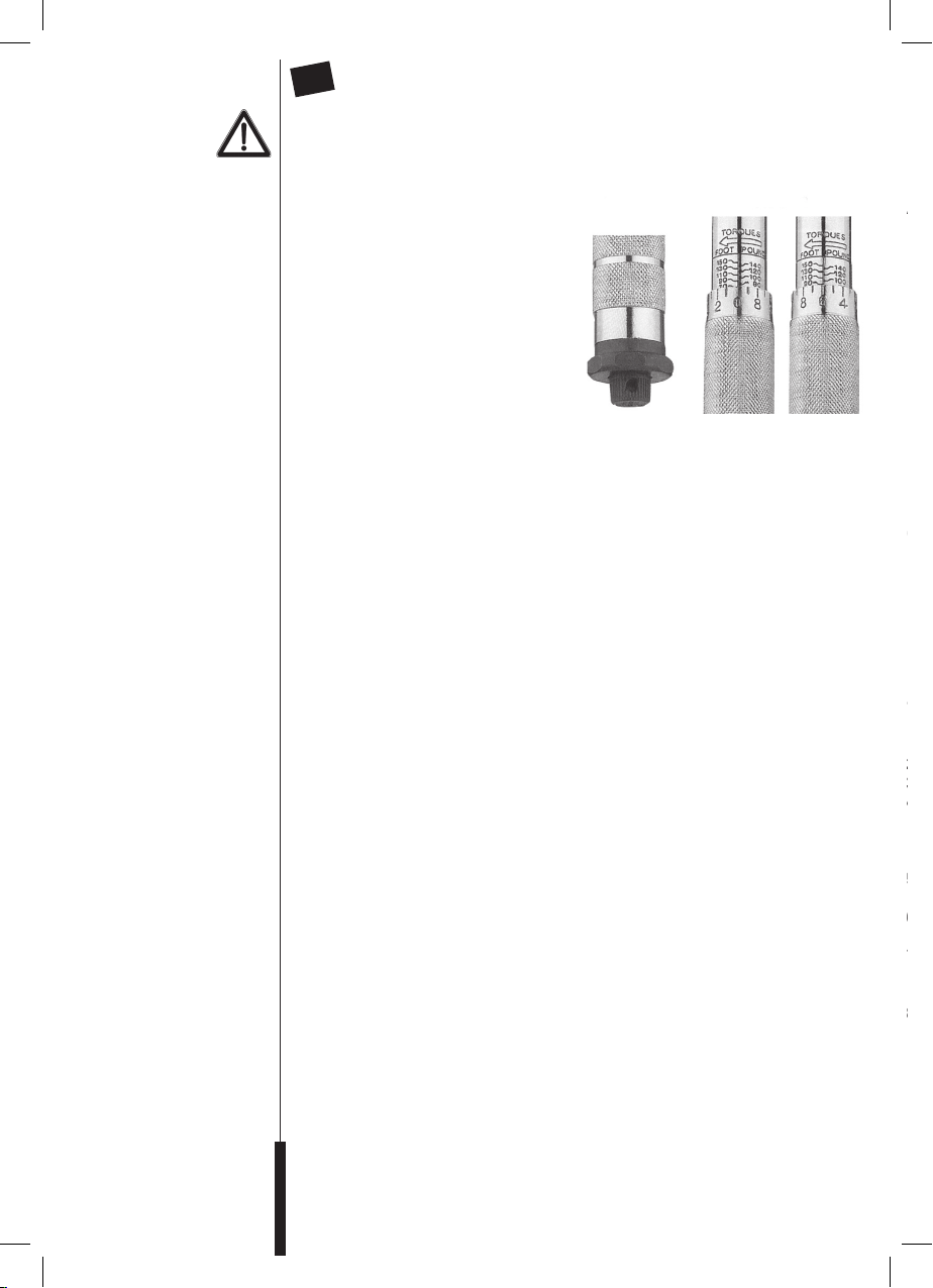
A) Hold the wrench in the left hand,
looking at the graduated scale, then
release the knurled handle by turning
the knurled screw anticlockwise. See
Fig. 1.
B) Set the required torque precisely
using the scale on the housing.
Example: 86 ft.lbs.
1. Rotate the knurled handle until the
0 mark on the chamfered edge of
the handle points to the vertical
marking on the housing and is flush
with the scale value 80 ft.Ibs.
2. Rotate the handle clockwise until the 6 ft.Ibs. marking on the chamfered edge of
the handle points to the vertical line on the housing.
3. Lock the handle by turning the knurled screw clockwise.
The wrench is now set for a torque of 86 ft. Ibs. and is ready for use. See Fig. 2.
C) Make other settings (Nm) in the same manner as when making settings using ft.lbs.
D) Attach the appropriate socket or other tool on the external square, then place it on the
socket or bolt. Rotate the handle until the wrench audibly or perceptibly engages.
When you loosen the tension and release the wrench, it automatically resets itself
for the next use.
Do not tighten any further after the wrench is engaged. Ensure, particularly when
the torque values are low, that no further tension is applied after the wrench has
engaged.
1. If the wrench has not been used for a while or has been in storage, operate it several
times with a low torque so that the special internal lubrication system can wet the
moving parts inside with lubricant.
2. When not in use, set the wrench to the lowest torque.
3. Do not rotate the handle past the lowest torque.
4. Do not continue to pull on the wrench after the preset torque has been reached and
the wrench is engaged. The pressure must be removed from the handle and the
wrench so that it can automatically reset itself. Further pressure after the wrench is
engaged will lead to the tightened section being damaged by excessive torque
5. The tool is sturdy and is designed for workshop operation, but it is a precision
measuring instrument and must be handled accordingly.
6. Clean the wrench by wiping it off: Do not immerse in any kind of cleaning agent;
this can affect the special lubricant filled into the wrench at the factory.
7. The torque wrench was calibrated and verified before leaving the factory and
is accurate to +/- 4%. This is a precision measuring instrument.
The owner is responsible for regular calibration and maintenance.
8. This torque wrench is only intended to be used for the controlled tightening of screws
and nuts. Make a regular conformity test with the tool after 5000 load changes and / or
a maximum period of 12 months. If this requirement is not kept, the function / accuracy
is no longer appropriate. The torque wrenches are measuring / testing devices and as
such they may not be used to loosen screw connections.
Length: 425-446 mm (40-210 Nm)
Weight (without accessories): 1.1 kg
Torque: 40-210 Nm
Sicherheit
Verwendung
Ihres neuen
Drehmomentschlüssel
Achtung!
Reinigungshinweise:
Technische Daten:
Einstellen des Auslösedrehmoments
DE
Bitte lesen Sie diese Bedienungsanleitung aufmerksam durch, bevor Sie den Drehmomentschlüssel benutzen.
Bewahren Sie diese Anleitung gut auf. Händigen Sie alle Unterlagen bei Weitergabe des
Drehmomentschlüssels an Dritte ebenfalls aus.
A) Halten Sie den Schlüssel mit Sicht auf
die Gradeinteilung in der linken Hand,
entriegeln Sie den Rändelgriff durch
Drehen der Rändelschraube gegen
den Uhrzeigersinn. Siehe Abb. 1.
B) Stellen Sie das gewünschte Dreh-
moment anhand der Skala auf dem
Gehäuse präzise ein.
Beispiel: 86 ft.lbs.
1. Drehen Sie den Rändelgriff, bis die
0-Markierung am abgeschrägten
Rand des Griffs auf die vertikale
Markierung am Gehäuse zeigt und
mit dem Skalenwert 80 ft.Ibs fluchtet.
2. Drehen Sie den Griff im Uhrzeigersinn, bis die 6 ft.Ibs-Markierung am
abgeschrägten Rad des Griffs auf die vertikale Linie am Gehäuse zeigt.
3. Verriegeln Sie den Griff durch Drehen der Rändelschraube im Uhrzeigersinn.
Der Schlüssel ist jetzt auf ein Drehmoment von 86 ft. Ibs eingestellt und
einsatzbereit. Siehe Abb. 2.
C) Nehmen Sie weitere Einstellungen (Nm) genau so vor, wie eine Einstellung auf ft.lb.
D) Stecken Sie die passende Nuss oder einen anderen Aufsatz auf den Außenvierkant,
setzen Sie diesen auf die Mutter oder Schraube auf, drehen Sie den Griff, bis der
Schlüssel fühl- und/oder hörbar einschnappt. Wenn Sie den Zug lockern und den
Schlüssel loslassen, setzt er sich automatisch für den nächsten Einsatz zurück.
Nach Schlüsselfreigabe nicht mehr weiter anziehen. Achten Sie insbesondere bei
niedrigen Drehmomentwerten darauf, dass kein weiterer Zug ausgeübt wird, wenn
der Schlüssel einschnappt.
1. Ist der Schlüssel längere Zeit unbenutzt oder eingelagert gewesen, nutzen Sie ihn
mehrere Mal mit einem niedrigen Drehmoment, sodass die spezielle interne Schmierung die beweglichen Teile im Inneren wieder neu mit Schmiermittel benetzen kann.
2. Bei Nichtbenutzung stellen Sie den Schlüssel auf das niedrigste Drehmoment ein.
3. Drehen Sie den Griff nicht über das niedrigste Drehmoment hinaus.
4. Ziehen Sie nicht weiter am Schlüssel, nachdem das voreingestellte Drehmoment
erreicht ist und der Schlüssel freigegeben wurde. Der Druck muss vom Griff und dem
Schlüssel vorgenommen werden, damit er sich automatisch rücksetzen kann. Weiterer
Druck nach Freigabe des Schlüssels führt dazu, dass das angezogene Teil durch übermäßiges Drehmoment beschädigt wird.
5. Das Werkzeug ist robust und für den Werkstattgebrauch ausgelegt, jedoch ebenfalls
ein Präzisionsmessinstrument, das auch als solches behandelt werden sollte.
6. Reinigen Sie den Schlüssel durch Abwischen: Tauchen Sie ihn nicht in Reinigungsmittel jeglicher Art; dadurch kann das Spezialschmiermittel beeinträchtigt werden, mit
dem der Schlüssel werkseitig befüllt wurde.
7. Der Drehmomentschlüssel wurde vor dem Verlassen des Werkes kalibriert und geprüft
und ist bis auf +/- 4% genau. Dies ist ein Präzisionsmessinstrument. Der Besitzer ist
dafür verantwortlich, es regelmäßig zu kalibrieren und zu warten.
8. Dieser Drehmomentschlüssel ist ein Mess- / Kontrollinstrument und darf als solches
nicht zum Lösen von Schrauben verwendet werden. Führen Sie nach 5.000 Lastwech-
seln und/oder einer maximalen Dauer von 12 Monaten einen regelmäßigen Konformitätstest mit dem Werkzeug durch. Wenn diese Anforderung nicht eingehalten wird, ist
die Funktion und die Genauigkeit nicht mehr gegeben.
Länge: 425-446 mm (40-210 Nm)
Gewicht (ohne Zubehör): 1,1 kg
Drehmomentbereich: 40-210 Nm
Abb. 1 Abb. 2
146001_146002_AZ_Drehmomentschlüssel_CTR-IM-INT-OEF_A5_181019.indd 2 23.10.18 13:38
Setting the release torque
GB
Please read these operating instructions carefully before using the torque wrench.
Keep the instructions in a safe place.
Pass on all documentation when passing on the torque wrench to another person.
Safety
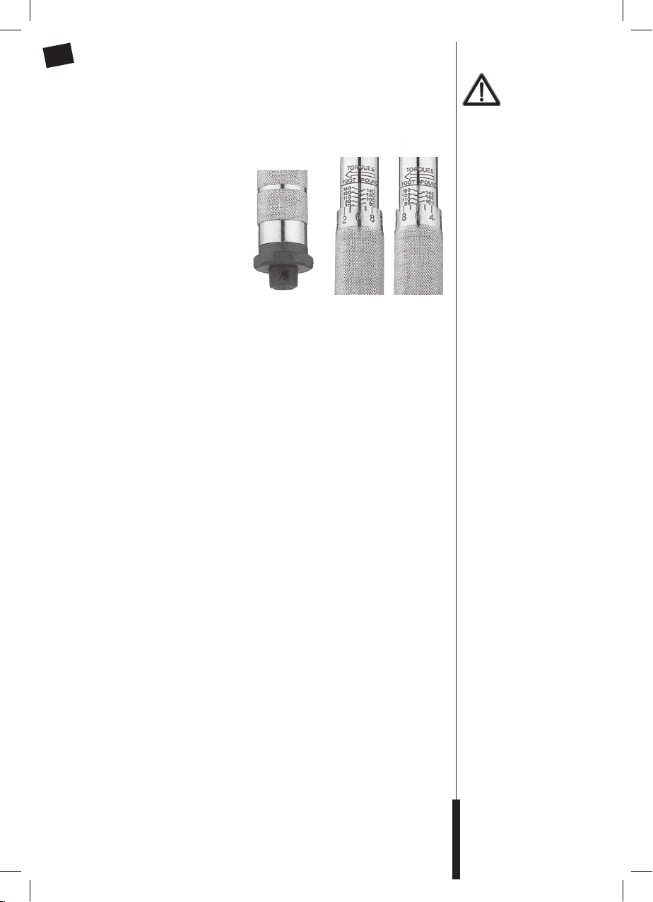
A) Hold the wrench in the left hand,
looking at the graduated scale, then
release the knurled handle by turning
the knurled screw anticlockwise. See
Fig. 1.
B) Set the required torque precisely
using the scale on the housing.
Example: 86 ft.lbs.
1. Rotate the knurled handle until the
0 mark on the chamfered edge of
the handle points to the vertical
marking on the housing and is flush
with the scale value 80 ft.Ibs.
2. Rotate the handle clockwise until the 6 ft.Ibs. marking on the chamfered edge of
the handle points to the vertical line on the housing.
3. Lock the handle by turning the knurled screw clockwise.
The wrench is now set for a torque of 86 ft. Ibs. and is ready for use. See Fig. 2.
C) Make other settings (Nm) in the same manner as when making settings using ft.lbs.
D) Attach the appropriate socket or other tool on the external square, then place it on the
socket or bolt. Rotate the handle until the wrench audibly or perceptibly engages.
When you loosen the tension and release the wrench, it automatically resets itself
for the next use.
Do not tighten any further after the wrench is engaged. Ensure, particularly when
the torque values are low, that no further tension is applied after the wrench has
engaged.
1. If the wrench has not been used for a while or has been in storage, operate it several
times with a low torque so that the special internal lubrication system can wet the
moving parts inside with lubricant.
2. When not in use, set the wrench to the lowest torque.
3. Do not rotate the handle past the lowest torque.
4. Do not continue to pull on the wrench after the preset torque has been reached and
the wrench is engaged. The pressure must be removed from the handle and the
wrench so that it can automatically reset itself. Further pressure after the wrench is
engaged will lead to the tightened section being damaged by excessive torque
5. The tool is sturdy and is designed for workshop operation, but it is a precision
measuring instrument and must be handled accordingly.
6. Clean the wrench by wiping it off: Do not immerse in any kind of cleaning agent;
this can affect the special lubricant filled into the wrench at the factory.
7. The torque wrench was calibrated and verified before leaving the factory and
is accurate to +/- 4%. This is a precision measuring instrument.
The owner is responsible for regular calibration and maintenance.
8. This torque wrench is only intended to be used for the controlled tightening of screws
and nuts. Make a regular conformity test with the tool after 5000 load changes and / or
a maximum period of 12 months. If this requirement is not kept, the function / accuracy
is no longer appropriate. The torque wrenches are measuring / testing devices and as
such they may not be used to loosen screw connections.
Fig. 1 Fig. 2
Using your
new torque wrench
Attention!
Cleaning information:
Length: 425-446 mm (40-210 Nm)
Weight (without accessories): 1.1 kg
Torque: 40-210 Nm
146001_146002_AZ_Drehmomentschlüssel_CTR-IM-INT-OEF_A5_181019.indd 3 23.10.18 13:38
Technical data:

Si prega di leggere attentamente le seguenti istruzioni per l’uso prima di utilizzare la
chiave dinamometrica.
Conservare correttamente le presenti istruzioni. Consegnare inoltre tutti i documenti
relativi alla chiave dinamometrica in caso di trasferimento a terzi.
A) Nella mano sinistra tenere la chiave
con visuale sulla scala, per sbloccare
l‘impugnatura zigrinata, ruotare la vite
a testa cilindrica zigrinata in senso
antiorario. Vedere fig. 1.
B) Impostare precisamente la coppia
desiderata in base alla scala sulla
custodia.
Esempio: 86 ft.lbs.
1. Ruotare il manico zigrinato fino
a che la marcatura 0 sul bordo
smussato del manico non indica la
marcatura verticale sulla custodia ed è allineata con il valore sulla scala di 80 ft.Ibs.
2. Ruotare il manico in senso orario fino a che la marcatura 6 ft.Ibs sul bordo
smussato del manico non indica la linea verticale sulla custodia.
3.
Per bloccare l‘impugnatura, ruotare la vite a testa cilindrica zigrinata in senso orario.
Ora la chiave è impostata su una coppia di 86 ft. Ibs ed è pronta all’uso.
Vedere fig. 2.
C) Seguire lo stesso procedimento usato per ft.lb per ulteriori impostazioni (Nm).
D) Inserire l’adattatore adatto o un altro attacco sul quadro maschio, posizionarlo sul
dado o sulla vite, ruotare il manico finché non si sente al tatto e/o all‘udito che la
chiave si chiude a scatto. Quando si allenta la trazione e si rilascia la chiave, questa
si resetta automaticamente per il successivo utilizzo.
Non continuare a tirare dopo il rilascio della chiave. Per valori di coppia ridotti
assicurarsi in particolare che non venga esercitata ulteriore trazione quando la
chiave si chiude a scatto.
1. Se la chiave non viene utilizzata o se viene conservata per un lungo periodo, utilizzarla
più volte con una coppia ridotta per fare in modo che la speciale lubrificazione interna
possa rilubrificare le parti in movimento all’interno con il lubrificante.
2. In caso di non utilizzo impostare la chiave alla coppia inferiore.
3. Non ruotare il manico oltre la coppia inferiore.
4. Non tirare ulteriormente la chiave dopo aver raggiunto la coppia preimpostata
e dopo aver rilasciato la chiave. Rimuovere la pressione dal manico e dalla chiave per
fare in modo che si possa ripristinare automaticamente. Una pressione ulteriore dopo
il rilascio della chiave danneggia la parte serrata con una coppia eccessiva.
5. L’attrezzo è robusto e progettato per l’uso in officina, ma è comunque uno strumento di
misura di precisione che deve essere trattato come tale.
6. Pulire la chiave con un panno. Non immergerla in detergenti di alcun tipo per non
danneggiare il lubrificante speciale con il quale la chiave è stata riempita in fabbrica.
7. La chiave dinamometrica è stata calibrata e testata prima di uscire dalla fabbrica ed è
precisa fino al +/- 4%. Si tratta di uno strumento di misura di precisione.
Il proprietario è tenuto a calibrarlo e a sottoporlo a manutenzione in modo regolare.
8. Questa chiave dinamometrica funge esclusivamente al serraggio controllato di viti e
dadi. Eseguire un regolare test di conformità sull‘utensile dopo 5.000 variazioni di cari-
co e / o un periodo massimo di 12 mesi. Se questo requisito non viene osservato il fun-
zionamento adeguato e/o l‘accuratezza dell‘utensile non sono più garantiti. Le chiavi
dinamometriche sono utensili di misurazione / controllo e in quanto tali non possono
essere utilizzate per allentare collegamenti a vite.
Lunghezza: 425-446 mm (40-210 Nm)
Peso (senza accessori): 1,1 kg
Coppia: 40-210 Nm
IT
Sécurité
Utilisation de
votre nouvelle
clé dynamométrique
Attention !
Consignes de nettoyage :
Caractéristiques
techniques :
Réglage du couple de déclenchement
FR
Veuillez lire attentivement ce mode d’emploi avant d’utiliser la clé dynamométrique.
Conservez soigneusement ce mode d’emploi.
Remettez également tous les documents à la personne à qui vous cédez la
clé dynamométrique.
A) Tenez la clé dans votre main gauche
avec vue sur la graduation,
déverrouillez la poignée à écrou
moleté en tournant la vis moletée
dans le sens antihoraire. Voir Fig. 1.
B) Réglez précisément le couple
souhaité à l’aide de l’échelle sur
le boîtier.
Exemple : 86 ft.lbs.
1. Tournez la poignée à molette
jusqu’à ce que le repère 0 sur le
bord biseauté de la poignée
montre le repère vertical sur le boîtier et soit aligné sur la valeur graduée à 80 ft.Ibs.
2. Tournez la poignée dans le sens horaire jusqu’à ce que le repère 6 ft.Ibs sur la
roulette biseautée de la poignée montre la ligne verticale sur le boîtier.
3. Verrouillez la poignée en tournant la vis moletée dans le sens horaire.
La clé est maintenant réglée à un couple de 86 ft. Ibs et prête à l’emploi. Voir Fig. 2.
C) Effectuez d’autres réglages (Nm) exactement comme un réglage sur ft.lbs.
D) Fichez la noix convenant ou une autre garniture sur le carré mâle, posez-le sur l’écrou
ou la vis, tournez la poignée jusqu’à ce que vous sentiez et/ou entendez que la
clé s’enclenche. Si vous desserrez la traction et relâchez la clé, elle se remet
automatiquement en position initiale pour la prochaine utilisation.
Ne plus continuer à resserrer après le déblocage de la clé. Veillez à ne plus
exercer de traction quand la clé s’enclenche, ceci particulièrement avec de faible
valeur de couple.
1. Si la clé est restée longtemps inutilisée ou stockée, utilisez-la plusieurs fois avec
un couple de faible valeur pour que le graissage interne spécial puisse humecter de
nouveau de lubrifiant les pièces mobiles à l’intérieur.
2. En cas de non utilisation, réglez la clé au couple la plus faible.
3. Ne tournez pas la poignée au-delà du couple le plus faible.
4. Ne continuez pas à serrer la clé après que le couple préréglé est atteint et la clé
débloquée. La pression doit être enlevée de la poignée et de la clé pour qu’elle
puisse revenir automatiquement en position initiale. La poursuite de la pression
après déblocage de la clé fait que la pièce serrée est endommagée par le couple
trop important.
5. L’outil est robuste et conçu pour être utilisé à l’atelier, mais également comme
instrument de mesure de précision qui doit aussi être traité en tant que tel.
6. Nettoyez la clé en l’essuyant : ne la plongez pas dans un nettoyant de type
quelconque ; cela peut influencer négativement le lubrifiant spécial avec lequel la
clé a été remplie à l’usine.
7. La clé dynamométrique a été calibrée et contrôlée avant de quitter l’usine et indique
une précision jusqu’à +4%. Il s’agit d’un instrument de mesure de précision.
Le propriétaire est responsable de son calibrage et de son entretien réguliers.
8. Cette clé dynamométrique est uniquement destinée à être utilisée pour le serrage con-
trôlé de vis et d‘écrous. Veuillez effectuer un test de conformité standard avec l‘outil
après 5 000 changements de charge et / ou après une période de 12 mois au maximum.
Si cette obligation n‘est pas respectée, le fonctionnement ou la précision de l’appareil
ne seront plus satisfaisants. Les clés dynamométriques sont des appareils de mesure
et de contrôle, qui ne peuvent pas être utilisés pour desserrer des raccords vissés.
Longueur : 425-446 mm (40-210 Nm)
Poids (sans accessoires) : 1,1 kg
Couple : 40-210 Nm
Fig. 1 Fig. 2
146001_146002_AZ_Drehmomentschlüssel_CTR-IM-INT-OEF_A5_181019.indd 4 23.10.18 13:38

Impostazione della coppia di azionamento
IT
Si prega di leggere attentamente le seguenti istruzioni per l’uso prima di utilizzare la
chiave dinamometrica.
Conservare correttamente le presenti istruzioni. Consegnare inoltre tutti i documenti
relativi alla chiave dinamometrica in caso di trasferimento a terzi.
Sicurezza
A) Nella mano sinistra tenere la chiave
con visuale sulla scala, per sbloccare
l‘impugnatura zigrinata, ruotare la vite
a testa cilindrica zigrinata in senso
antiorario. Vedere fig. 1.
B) Impostare precisamente la coppia
desiderata in base alla scala sulla
custodia.
Esempio: 86 ft.lbs.
1. Ruotare il manico zigrinato fino
a che la marcatura 0 sul bordo
smussato del manico non indica la
marcatura verticale sulla custodia ed è allineata con il valore sulla scala di 80 ft.Ibs.
2. Ruotare il manico in senso orario fino a che la marcatura 6 ft.Ibs sul bordo
smussato del manico non indica la linea verticale sulla custodia.
3.
Per bloccare l‘impugnatura, ruotare la vite a testa cilindrica zigrinata in senso orario.
Ora la chiave è impostata su una coppia di 86 ft. Ibs ed è pronta all’uso.
Vedere fig. 2.
C) Seguire lo stesso procedimento usato per ft.lb per ulteriori impostazioni (Nm).
D) Inserire l’adattatore adatto o un altro attacco sul quadro maschio, posizionarlo sul
dado o sulla vite, ruotare il manico finché non si sente al tatto e/o all‘udito che la
chiave si chiude a scatto. Quando si allenta la trazione e si rilascia la chiave, questa
si resetta automaticamente per il successivo utilizzo.
Non continuare a tirare dopo il rilascio della chiave. Per valori di coppia ridotti
assicurarsi in particolare che non venga esercitata ulteriore trazione quando la
chiave si chiude a scatto.
1. Se la chiave non viene utilizzata o se viene conservata per un lungo periodo, utilizzarla
più volte con una coppia ridotta per fare in modo che la speciale lubrificazione interna
possa rilubrificare le parti in movimento all’interno con il lubrificante.
2. In caso di non utilizzo impostare la chiave alla coppia inferiore.
3. Non ruotare il manico oltre la coppia inferiore.
4. Non tirare ulteriormente la chiave dopo aver raggiunto la coppia preimpostata
e dopo aver rilasciato la chiave. Rimuovere la pressione dal manico e dalla chiave per
fare in modo che si possa ripristinare automaticamente. Una pressione ulteriore dopo
il rilascio della chiave danneggia la parte serrata con una coppia eccessiva.
5. L’attrezzo è robusto e progettato per l’uso in officina, ma è comunque uno strumento di
misura di precisione che deve essere trattato come tale.
6. Pulire la chiave con un panno. Non immergerla in detergenti di alcun tipo per non
danneggiare il lubrificante speciale con il quale la chiave è stata riempita in fabbrica.
7. La chiave dinamometrica è stata calibrata e testata prima di uscire dalla fabbrica ed è
precisa fino al +/- 4%. Si tratta di uno strumento di misura di precisione.
Il proprietario è tenuto a calibrarlo e a sottoporlo a manutenzione in modo regolare.
8. Questa chiave dinamometrica funge esclusivamente al serraggio controllato di viti e
dadi. Eseguire un regolare test di conformità sull‘utensile dopo 5.000 variazioni di carico e / o un periodo massimo di 12 mesi. Se questo requisito non viene osservato il funzionamento adeguato e/o l‘accuratezza dell‘utensile non sono più garantiti. Le chiavi
dinamometriche sono utensili di misurazione / controllo e in quanto tali non possono
essere utilizzate per allentare collegamenti a vite.
Fig. 1 Fig. 2
Utilizzo della
nuova chiave
dinamometrica
Attenzione!
Istruzioni per la pulizia:
Lunghezza: 425-446 mm (40-210 Nm)
Peso (senza accessori): 1,1 kg
Coppia: 40-210 Nm
146001_146002_AZ_Drehmomentschlüssel_CTR-IM-INT-OEF_A5_181019.indd 5 23.10.18 13:38
Dati tecnici:

Ustawianie żądanej wartości momentu obrotowego
PL
Przed użyciem klucza dynamometrycznego należy dokładnie zapoznać się z niniejszą
instrukcją obsługi.
Instrukcję tę należy zachować! W przypadku przekazania klucza dynamometrycznego osobom
Bezpieczeństwo
Używanie klucza
dynamometrycznego
Uwaga!
Wskazówki dotyczące
czyszczenia:
Parametry techniczne:
trzecim należy przekazać również wszystkie dołączone do narzędzia dokumenty
A) Klucz należy trzymać w lewej ręce tak,
aby była widoczna stopniowa podziałka.
Należy odblokować uchwyt radełkowy,
obracając śrubę radełkowaną w kierunku przeciwnym do ruchu wskazówek
zegara. Patrz rys. 1.
B) Dokładnie ustawić żądaną wartość
momentu obrotowego w oparciu o
skalę na obudowie.
Przykład: 86 ft.lbs.
1. Przekręcić radełkowany uchwyt do
momentu, aż oznaczenie punktu
zerowego na skośnie ściętym brzegu uchwytu będzie wskazywało na pionowe
oznaczenie na obudowie i zbiegnie się z wartością 80 ft.Ibs na skali.
2. Zablokować uchwyt, obracając śrubę radełkowaną w kierunku zgodnym z ruchem
wskazówek zegara.
3. Zablokować uchwyt, przekręcając nakrętkę zabezpieczającą w kierunku zgodnym z
ruchem wskazówek zegara. Gdy wartość momentu obrotowego klucza jest ustawiona
na 86 ft. Ibs, jest on gotowy do użycia. Patrz rys. 2.
C) Pozostałe wartości (Nm) należy ustawić w taki sam sposób, jak wartość ft.lb.
D) Założyć odpowiednią nakrętkę lub inną nasadkę na czworokątną końcówkę klucza i
nasadzić ją na nakrętkę lub śrubę. Przekręcić uchwyt aż do wyczuwalnego i/lub słyszalnego
zatrzaśnięcia. Po zwolnieniu nacisku i odciążeniu klucza, klucz powraca automatycznie do
pozycji wyjściowej i jest gotowy do kolejnego zastosowania.
Po zwolnieniu klucza nie wolno kontynuować dokręcania. Szczególnie w przypadku
niskich wartości momentu obrotowego należy uważać, aby nie kontynuować dokręcania,
gdy klucz się zatrzasnął.
1. Jeśli klucz nie był używany przez dłuższy czas, należy użyć go kilkakrotnie z ustawioną niską
wartością momentu obrotowego. Dzięki temu ruchome części wewnątrz narzędzia zostaną
ponownie nasmarowane przez specjalny środek smarny, którym napełnione jest narzędzie.
2. Jeżeli klucz nie jest używany, należy ustawić najniższą wartość momentu obrotowego.
3. Podczas przekręcania uchwytu nie wolno przekroczyć najniższego momentu obrotowego.
4.
Nie wolno kontynuować dokręcania, gdy został osiągnięty ustawiony wcześniej moment obrotowy i klucz został zwolniony. Nacisk musi zostać wywołany przez uchwyt i klucz, aby mógł on
potem powrócić do pozycji wyjściowej. Dalszy nacisk po zwolnieniu klucza może doprowadzić
do uszkodzenia dokręcanych części z powodu zbyt dużego momentu obrotowego.
5. Klucz jest wytrzymałym narzędziem przeznaczonym do użytku w warsztatach,
lecz także narzędziem precyzyjnym i należy obchodzić się z nim ostrożnie.
6. Klucz należy czyścić poprzez wycieranie. Nie należy zanurzać klucza w jakichkolwiek
środkach czyszczących, ponieważ mogą one powodować pogorszenie właściwości
smarnych środka smarnego, którym klucz został fabrycznie napełniony.
7. Klucz dynamometryczny został fabrycznie skalibrowany z dokładnością do
i sprawdzony. Klucz jest narzędziem precyzyjnym. Właściciel narzędzia jest
odpowiedzialny za przeprowadzanie jego regularnej kalibracji i konserwacji.
8.
Klucza dynamometrycznego należy używać wyłącznie w celu kontrolowanego dokręcania
śrub i nakrętek. Należy regularnie wykonywać test zgodności z użyciem narzędzia po 5000
zmianach obciążenia i/lub po upływie okresu maksymalnie 12 miesięcy. W przypadku
niespełnienia powyższego wymogu narzędzie przestaje spełniać kryteria odpowiedniego
działania / dokładności. Klucze dynamometryczne są narzędziami pomiarowymi /
testowymi i jako takie nie mogą być używane do odkręcania połączeń śrubowych.
Długość:
Waga (bez wyposażenia): 1,1 kg
Moment obrotowy: 40-210 Nm
425-446 mm (40-210 Nm)
Rys. 1 Rys. 2
.
+/-
4%
146001_146002_AZ_Drehmomentschlüssel_CTR-IM-INT-OEF_A5_181019.indd 6 23.10.18 13:38

SI
Nastavitev sprožitvenega zateznega momenta
Pred uporabo momentnega ključa pozorno preberite ta navodila za uporabo.
Ta navodila shranite na dosegljivem mestu.
Če momentni ključ predate tretji osebi, ji izročite tudi celotno dokumentacijo.
Varnost
A) Držite ključ s pogledom na stopinjsko
lestvico v levi roki, odklenite rebričasti
ročaj z vrtenjem vijaka z rebričasto
glavo v nasprotni smeri urnega kazalca.
Glejte sl. 1.
B) Natančno nastavite želeni zatezni
moment z uporabo lestvice na ohišju.
Primer: 86 ft.lbs.
1. Vrtite rebričast ročaj, dokler oznaka
0 na poševnem robu ročaja ne kaže
na navpično oznako na ohišju in ni
poravnana z vrednostjo na lestvici
80 ft.Ibs.
2. Vrtite ročaj v smeri urnega kazalca, dokler oznaka 6 ft.Ibs na poševnem robu ročaja ne
kaže na navpično črto na ohišju.
3. Zaklenite ročaj z vrtenjem vijaka z rebričasto glavo v smeri urnega kazalca. Ključ je zdaj
na zateznem momentu 86 ft. Ibs je nastavljen in pripravljen za uporabo. Glejte sl. 2.
C) Nadaljnje nastavitve (Nm) izvedite na isti način, kot nastavitev na ft.lb.
D) Nataknite ustrezen vložek ali drug nastavek na štirirobni nastavek, namestite ga na matico
ali vijak, vrtite ročaj, dokler ključ občutno in/ali slišno ne zaskoči. Če pritegnitev razrahljate
in ključ spustite, se sam samodejno namesti nazaj za naslednjo uporabo.
Po sprostitvi ključa ne zategujte več. Bodite posebej pazljivi, da ne zategujete, ko ključ
zaskoči.
1. Če ključa dalj časa ne uporabljate ali če je bil uskladiščen, ga večkrat uporabite z nizkim
zateznim momentom tako, da posebno notranje mazanje premične dele v notranjosti
ponovno premaže z mazivom.
2. Ko ključa ne uporabljate, ga nastavite na najnižji zatezni moment.
3. Ročaj ne zavrtite čez najnižji zatezni moment.
4. Ključa ne zategujte več, ko je dosežen prednastavljeni zatezni moment in se je ključ sprostil.
Pritisk morata izvajati ročaj in ključ, da se lahko samodejno namesti nazaj. Dodatni pritisk
po sprostitvi ključa povzroči, da se zategnjen del zaradi previsokega zateznega momenta
poškoduje.
5. Orodje je robustno in izdelano za uporabo v delavnici, vendar je tudi natančen merilni
instrument, ki ga je treba kot takega tudi uporabljati.
6. Ključ čistite tako, da ga obrišete: ne potapljajte ga v nikakršna čistilna sredstva;
sicer se lahko poslabša posebno mazivo, s katerim je bil ključ tovarniško napolnjen.
7. Momentni ključ je bil v tovarni umerjen in preizkušen ter je natančen do +/– 4 %.
To je natančen merilni instrument.
Lastnik je odgovoren za redno umerjanje in vzdrževanje.
8. Momentni ključ je namenjen samo za preverjanje privitosti vijakov in matic. Izvedite reden
preizkus naprave po 5000-ih spremembah obremenitve / ali najkasneje v 12 mesecih.
Če teh zahtev ne upoštevate, potem delovanje / natančnost ni zagotovljena. Momentni
ključi so merilne / preizkusne naprave in se kot takšne ne smejo uporabljati za odvijanje in
privijanje vijakov.
Sl. 1 Sl. 2
Uporaba vašega novega
momentnega ključa
Pozor!
Napotki za čiščenje
Dolžina: 425-446 mm (40-210 Nm)
Teža (brez pribora): 1,1 kg
Območje zateznega momenta: 40-210 Nm
146001_146002_AZ_Drehmomentschlüssel_CTR-IM-INT-OEF_A5_181019.indd 7 23.10.18 13:38
Tehnični podatki

D Umrechnungstabelle / Conversion table / F Table de conversion /
I Tabella di conversione /
Tabela przeliczeniowa / Računska tabela
D Einheitenumrechnung
Unit conversion
F Conversion des unités
I Conversione unità
Przeliczanie jednostek
Preračun enot
146001_146002_AZ_Drehmomentschlüssel_CTR-IM-INT-OEF_A5_181019.indd 8 23.10.18 13:38

146001_146002_AZ_Drehmomentschlüssel_CTR-IM-INT-OEF_A5_181019.indd 9 23.10.18 13:38

MTS MarkenTechnikService
GmbH & Co. KG
Benzstr. 1
76185 Karlsruhe - Germany
www.mts-gruppe.com
Intertec Polska Sp. z o.o.
Stara Wieś, ul. Grodziska 22
05-830 Nadarzyn - Poland
www.intertec-polska.pl
Tegro AG · Ringstr. 3
8603 Schwerzenbach
Switzerland
www.tegro.ch
146001_146002_AZ_Drehmomentschlüssel_CTR-IM-INT-OEF_A5_181019.indd 10 23.10.18 13:38
22
PAP
Stand: 10/2018
146001 / 146002
 Loading...