

Cartoni Z105, Z102, Z110, Z101, Z107 User manual
...
Warranty
CARTONI S.p.A. warrants that this fluid head will be free
of defects in workmanship and materials and agrees that it will,
at its option, either repair or replace any defective part within 5
years from date of first purchase with no labor charge. Tripods,
dollies and all other relevant accessories are guaranteed 1 year
from the date of purchase.
This warranty does not apply to any CARTONI equipment
that is subject to misuse, abnormal service or handling or which
has been modified or changed in design or construction. Warranty claims must be submitted to the factory for verification or
to an authorized distributor designated by CARTONI S.p.A. in
writing.
Repairs by any unauthorized parties will void this warranty.
CARTONI S.p.A. shall not be liable for incidental or consequential
damages. All shipments of CARTONI S.p.A. equipment must be
insured during the warranty period.
ALL IMPLIED WARRANTIES ARE LIMITED TO THE
TIME PERIOD SET FORTH HEREIN.
Garanzia
CARTONI S.p.A. garantisce che questa testa fluida è priva di
difetti sia nella realizzazione che nei materiali e concorda che sarà
a sua discrezione riparata o sostituita in ogni parte difettosa entro
5 anni dalla data di vendita senza spese. Treppiedi, carrelli e ogni
altro accessorio sono garantiti per 1 anno dalla data di vendita.
Questa garanzia non si applica al prodotto CARTONI che sia
stato oggetto di uso improprio, manipolazioni o modifiche. Le
richieste di garanzia devono essere comunicate alla fabbrica o ad
un distributore designato ufficialmente da CARTONI S.p.A.
Le riparazioni non autorizzate fanno decadere la garanzia. CARTONI S.p.A. declina ogni responsabilità per incidenti o danni
conseguenti. Tutte le spedizioni di materiale della CARTONI
S.p.A. devono essere assicurate durante il periodo di garanzia.
TUTTE LE GARANZIE IMPLICITE SONO LIMITATE AL
PERIODO DI TEMPO QUI RIPORTATO.
PROFESSIONAL CAMERA SUPPORTS
Cartoni S.p.A.
Via Giuseppe Mirri, 13 - 00159 Roma - ITALY
tel. +39.06.4382002 - fax +39.06.43588293
e-mail: cartoni@cartoni.com
www.cartoni.com
PROFESSIONAL CAMERA SUPPORTS
User’s manual • Manuale operativo
scarsa illuminazione attivare l’illuminazione della bolla con il
pulsante (4). La luce si spegne automaticamente dopo circa
3
0 secondi.
4.0Bloccare i movimenti verticale e orizzontale con le leve (5) e
(6), impostare sia il controllo fl uido verticale (7) che il cont
robilanciamento (8) sul livello “1” (minimo).
5.0Per staccare la piastrina fi ssaggio camera (10) sbloccare la leva
(11) e premere il pulsante di sicurezza (15), quindi estrarre la
p
iastrina fi ssaggio camera (10) facendola scorrere indietro.
6.0Fissare la piastrina attacco camera sulla camera stessa cercan-
do di valutare il posizionamento per avere una confi gurazione bilanciata.
7.0Sistemare la camera sulla testata LASER; il dispositivo di si-
curezza comandato dal pulsante (15) scatterà assicurando la
p
iastrina alla testata. Spostare in avanti e indietro la piastrina
fi ssaggio camera sino ad ottenere il bilanciamento della camera stessa. Bloccare infi ne la piastra fi ssaggio camera tramite le leva (11).
8.0Tenere la camera in posizione orizzontale con una mano sul-
la leva di comando (9) e sbloccare il movimento verticale tra-
m
ite la levetta (6).
9.0Stabilire il corretto grado di controbilanciamento girando la
manopola (8) fi no a che il peso della camera venga complet
amente annullato. Eventualmente affi nare ulteriormente la
posizione della camera sbloccandone lo scorrimento tramite
la leva (11).
1
0
.
Sbloccare la leva (5) e selezionare il grado di smorzamento
fl uido desiderato tramite i selettori (7) e (14).
N
.B. QUANDO LA LUMINOSITÀ DELLA BOLLA DI
LIVELLAMENTO DIVENTA INSTABILE SOSTITUIRE LA
BATTERIA DA 9 VOLTS (3).
Laser
LASER • FLUID HEAD USER’S MANUAL
Thank you for choosing CARTONI. The CARTONI LASER fl uid
head is specifi cally designed for ENG digital camcorders weighing
from 4 to 12 kg (8 to 25 lbs).
The following set-up instructions are for the achievement of precise
pan, tilt and diagonal movement. To get optimum results from your
LASER system, the equipment set up is very important.
Before using the patented fl uid drag system, you will need to ac-
curately counterbalance your camera in order to allow the tilt drag
unit to operate in total freedom without gravity interference.
Please remember that pan and tilt lock levers must be set in lock
position before any attempt is made to fi t or remove equipment
mounted on the head. It is advisable to lock pan and tilt sections
when the camera is left unattended.
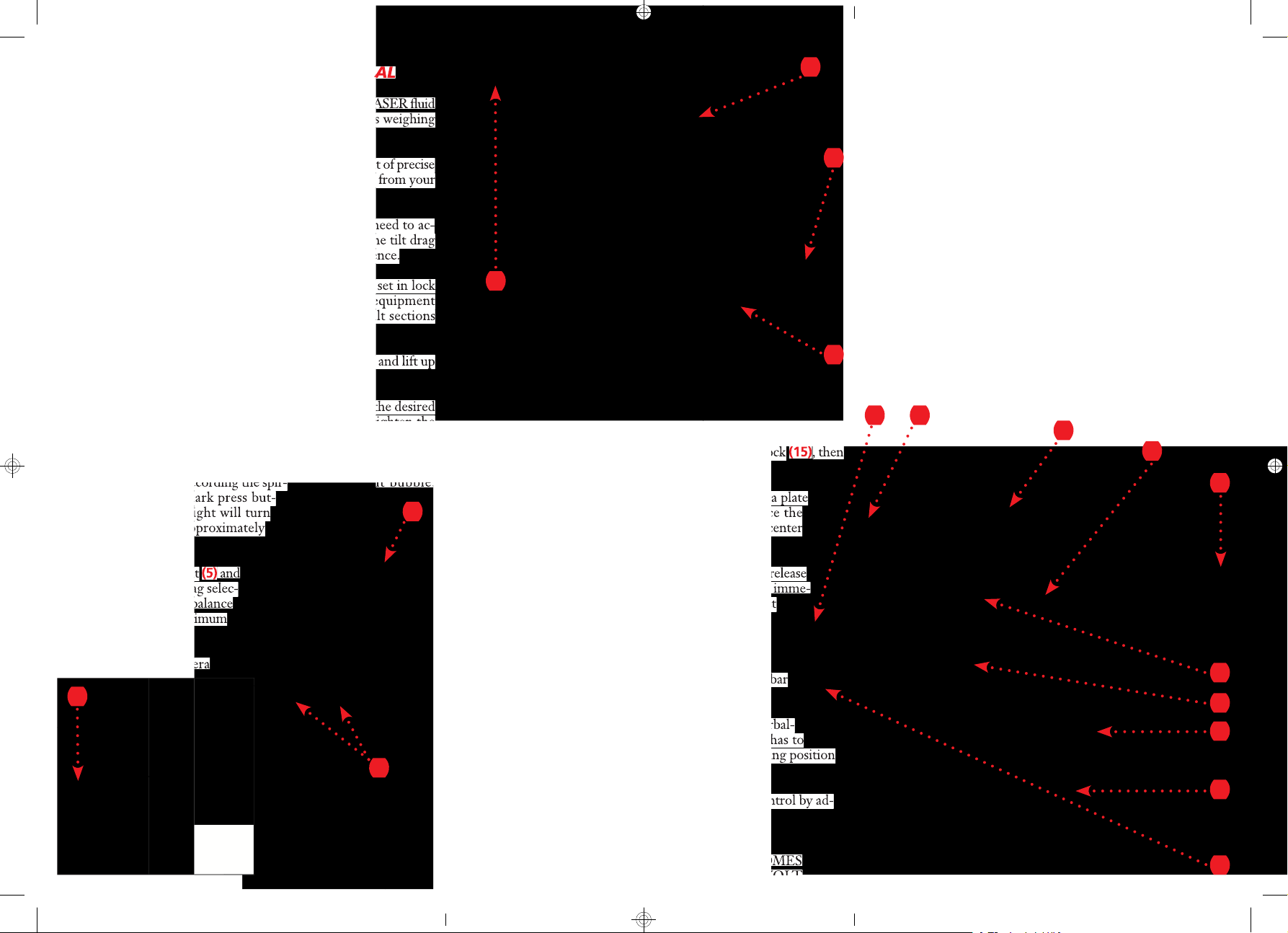
1.0Before opening the tripod, release all three levers (1) and lift up
the system at the desired height.
2.0Lock the three levers (1) and spread the tripod. Set the desired
leg angle by adjusting the extendible spreader and tighten the
knobs (2).
3.0Level the LASER on your tripod by loosening the knob under
the head and level according the spir- it bubble.
If stage or area is dark press but-
ton (4) for light. Light will turn
o
ff by itself after approximately
30 seconds.
4.0Lock both pan and tilt (5) and
(6), turn both tilt drag selec-
tor (7) and counterbalance
k
nob (8) to “1” (minimum
l
evel).
5.0To release the camera
ISTRUZIONI PER L’USO
DELLA TESTATA FLUIDA LASER
Vi ringraziamo per aver scelto una testata a fl uido CARTONI
LASER. La CARTONI LASER è il supporto ideale per i
camcor-
der digitali ENG di peso ta 4 e 12 kg.
Per ottenere il massimo rendimento dal sistema LASER e dei
movimenti panoramici perfetti , Vi invitiamo a seguire queste semplici sequenze ed istruzioni.
1.0Allungare il treppiede fi no all’altezza desiderata e bloccare la
posizione abbassando le leve (1).
2.0Aprire il treppiede e regolare l’angolazione desiderata delle
gambe fi ssando le stecche estensibili della stella tramite i pomelli (2).
3.0Procedere alla “messa in bolla” della testata allentando il po-
mello al di sotto della testata stessa, controllare la corretta
posizione orizzontale e stringere il pomello. In condizione di
plate (10) unlock the lever (11) and push the safety lock (15), then
e
xtract the camera plate (10) sliding it back.
6.0Attach the camera plate to the bottom of the camera plate
and firmly secure it with both screws. Try to place the
camera plate centered on the camera, keeping the center
of gravity position in mind.
7.0Place the camera on top of the LASER head; a quick release
locking system operated by the safety lock (15) will imme-
d
iately secure the camera to the head. Find correct
center of gravity position by sliding the camera plate
(10) front to back until you feel you have achieved
t
he desired balance. Lock in the lever (11).
8.0Hold the camera in horizontal position with the pan bar
(9) and release the tilt brake lever (6).
9.0Set the counterbalance system by turning the counterbal-
ance knob (8) to appropriate tension. The camera has to
s
tay at any tilt angle. Fine tune by adjusting the sliding position
unlocking the lever (11).
1
0
.
Unlock the pan brake lever (5) and set fl uid drag control by ad-
justing selectors (7) and (14).
N
.B. WHEN THE SPIRIT BUBBLE LIGHT BECOMES
UNSTABLE IT IS TIME TO CHANGE THE 9 VOLT
BATTERY (3).
it bubble.
(5)
and
and lift up
(15)
, then
2
1
1
9
10
6
5
6 11
7
14
8
4
15
9
10
3
 Loading...