

Advanced Microscopes
Advanced MicroscopesAdvanced Microscopes
Advanced Microscopes
Model CS series
Model CS seriesModel CS series
Model CS series
Instruction Manual
Instruction ManualInstruction Manual
Instruction Manual
COMPONENTS
COMPONENTSCOMPONENTS
COMPONENTS
Model CST-10
Model CST-10Model CST-10
Model CST-10
11
28
13
12
14
13
1
14
2
15
3
16
17
4
18
5
19
6
20
7
21
8
22
9
23
10
24
25
26
27
-2-
GENERAL GUIDE
GENERAL GUIDEGENERAL GUIDE
GENERAL GUIDE
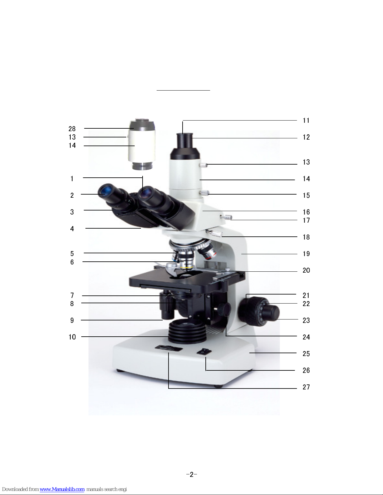
This tube can adopt a normal eyepiece
1.Interpupillary scale
1.Interpupillary scale1.Interpupillary scale
1.Interpupillary scale
for teaching or training purpose.
Interpupillary distance adjustable
from 48mm through 75mm.
13.Locking thumb screw
13.Locking thumb screw 13.Locking thumb screw
13.Locking thumb screw
for Photo tube
for Photo tube for Photo tube
for Photo tube
2.Eyepiece
2.Eyepiece2.Eyepiece
2.Eyepiece
Adjustable parfocal between
WF10x(FN=18) supplied as standard.
the vertical photo tube & the binocular.
WF15x & WF20x are available as option.
15.Locking thumb screw
15.Locking thumb screw 15.Locking thumb screw
15.Locking thumb screw
3.Dioptric adjustment ring
3.Dioptric adjustment ring3.Dioptric adjustment ring
3.Dioptric adjustment ring
for Vertical tube
for Vertical tube for Vertical tube
for Vertical tube
Adjustable a dioptric difference against
Adjustable a view angle of monit
o
r image.
right eye.
Provided on the left eyepiece tube.
16.Trinocular viewing head
16.Trinocular viewing head16.Trinocular viewing head
16.Trinocular viewing head
4.Binocular/Siedentopf type
4.Binocular/Siedentopf type 4.Binocular/Siedentopf type
4.Binocular/Siedentopf type
17.Sliding knob
17.Sliding knob17.Sliding knob
17.Sliding knob
With 30°inclined eyepiece tubes.
When the sliding knob is pulled out,
When adjusting interpupillary distance,
80% of the light comes to the photo tube
please grasp the right & left housings
and 20% to the binoculer tubes.
instead of eyepiece tubes.
18.Locking thumb screw
18.Locking thumb screw 18.Locking thumb screw
18.Locking thumb screw
5.Revolving Nosepiece
5.Revolving Nosepiece5.Revolving Nosepiece
5.Revolving Nosepiece
for Head
for Head for Head
for Head
Inward-facing(reversed) Quadruple
360°rotatable Monocular, Binocular or
Nosepiece on ball bearing mount with
Trinocular head.
click-stop mechanism for smooth and
Please use after tightening.
accurate operaton. Quintuple nosepiece
is also available as option.
19.Arm
19.Arm19.Arm
19.Arm
6.Objectives
6.Objectives6.Objectives
6.Objectives
20.Double layers Mechanical Stage
20.Double layers Mechanical Stage20.Double layers Mechanical Stage
20.Double layers Mechanical Stage
DIN Achromatic Objectives are provided.
141x131mm, travelling through 76x51mm.
Semi-plan & Plan objectives are also
2 slides can be held at a time for
available as option. 40x & 100x objectives
comparison viewing.
are spring-loaded.
21.Tension control ring
21.Tension control ring21.Tension control ring
21.Tension control ring
7.Substage Condenser
7.Substage Condenser7.Substage Condenser
7.Substage Condenser
The focusing movement torque can be
Abbe type NA=1.25 Condenser with iris
adjusted by turning the tension control
diaphragm & swing-out filter holder.
ring using the C-wrench.
Replaceable with Phase Turret
Condenser as option.
22.Coarse & 23.Fine Focusing handle
22.Coarse & 23.Fine Focusing handle22.Coarse & 23.Fine Focusing handle
22.Coarse & 23.Fine Focusing handle
Coaxial focusing adjustment devices.
8.Swing-out Filter holder
8.Swing-out Filter holder8.Swing-out Filter holder
8.Swing-out Filter holder
25mm Coarse focusing range, and
White & Blue filters are provided.
0.002mm fine focusing increments.
9.Mechanical stage control handle
9.Mechanical stage control handle9.Mechanical stage control handle
9.Mechanical stage control handle
24.Focusing handle
24.Focusing handle24.Focusing handle
24.Focusing handle
Coaxial drive handles on left hand.
for Sub stage Condenser assembly
for Sub stage Condenser assembly for Sub stage Condenser assembly
for Sub stage Condenser assembly
Focusable by rack and pinion.
10.Illuminator Condenser
10.Illuminator Condenser10.Illuminator Condenser
10.Illuminator Condenser
6v20w Halogen lamp.
25.Base
25.Base25.Base
25.Base
11.Photo tube cap
11.Photo tube cap11.Photo tube cap
11.Photo tube cap
26.On-Off switch for illuminator
26.On-Off switch for illuminator26.On-Off switch for illuminator
26.On-Off switch for illuminator
This cap should be put onto the photo
"I"=On,"0"=Off.
tube to prevent from dust when not using.
27.Light intensity control
27.Light intensity control27.Light intensity control
27.Light intensity control
12.Photo tube & 14.Vertical tube
12.Photo tube & 14.Vertical tube12.Photo tube & 14.Vertical tube
12.Photo tube & 14.Vertical tube
This tube is used for photomicrograph
28.C-Mount tube & 14.Vertical tube
28.C-Mount tube & 14.Vertical tube28.C-Mount tube & 14.Vertical tube
28.C-Mount tube & 14.Vertical tube
or viewing through a monitor.
replaceable as standard.
-3-
SETTING UP YOUR MICROSCOPE
SETTING UP YOUR MICROSCOPESETTING UP YOUR MICROSCOPE
SETTING UP YOUR MICROSCOPE
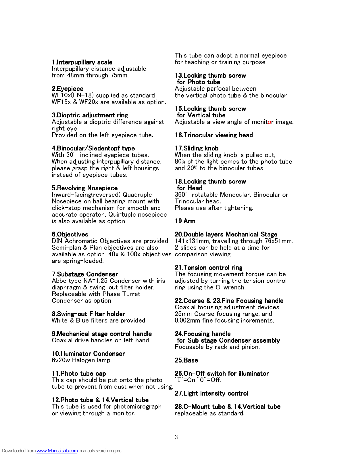
After opening the styroform container, check that you have the following parts
and accessories.
●Microscope stand complete
●Monocular, Binocular or Trinocular Viewing head
●WF10x Eyepiece(s) (pair for Binocular or Trinocular head)
●Objectives in plastic container
●White & Blue filters (1pce.each) and 2pcs. spare Fuses
●Spare 6v20w halogen lamp in carton box
●Electric power supply cord (Inlet type)
●C-Wrench for tension control
●Immersion oil in container
●Dust cover
●Instruction manual
In case of Trinocular viewing head
●Photo tube with straight tube & C-Mount tube with straight tube
1) Place the stand on a level, stable surface.
The stand is easiest to use when the stand is situated with the stage towards you.
2) Loosen the head locking thumb screw provided on the side of the arm, and put
the viewing head onto the receptacle. The head can turn full 360°inside the
receptacle. This permits observation from any direction.
Tighten the thumb screw to fix the head in any position you desire.
3) Put the eyepiece(s) into the eyepiece tube(s), being careful not to touch
the lenses.
4) Take out the objectives from the plastic containers and screw them into the
revolving nosepiece from the lowest magnification to the higher one in clockwise
direction as you face the upside of the microscope.
5)Turn the switch off(O) and connect the electric power supply cord.
Model CST-10
-4-
USING AND ADJUSTING YOUR MICROSCOPE
USING AND ADJUSTING YOUR MICROSCOPEUSING AND ADJUSTING YOUR MICROSCOPE
USING AND ADJUSTING YOUR MICROSCOPE
Viewing Head:
Viewing Head:Viewing Head:
Viewing Head:
The viewing head is inclined 30 degrees to enable comfortable observation and
360 degrees to permit observation from any direction. To rotate it, loosen the
head locking thumb screw and tighten it when the head is located at the position
you desire. Do not use the microscope without tightening the thumb screw,
as the optical alignment is adjusted to be used with the thumb screw tightened.
On the binicular or trinocular head, interpupillary adjustment are required.
To adjust the eyepieces to the interpupillary distance between your eyes,
please grasp the right & left housings instead of eyepiece tubes, and move them
together farther apart or closer in order to match your pupil distance.
Adjustment is proper when the field becomes comfortable and presents a full
single field. Read the interpupillary scale and remember the distance of your pupil
for your future use.
The binocular head mechanism of this model is
Siedentopf
SiedentopfSiedentopf
Siedentopf
type, and
the mechanical tube length is not changed to any position. (MTL.=160mm)
On the left eyepiece tube, the dioptric adjustment ring is provided. When there
is a dioptric difference between your eyes, while looking through the right eyepiece
with your right eye, use the fine focusing handle to get the sharpest image of the
specimen. Then, look through the left eyepiece with your left eye and turn the
dioptric adjustment ring until you get an image in the same sharpness as the right
one. Make the left eye adjustment without moving the focusing handle.
Arm:
Arm:Arm:
Arm:
The arm is fixed securely to the base and supports all the components above
the base. When moving the microscope, please grasp the arm and support the
bottom surface by the other hand. As the other parts are made delicately,
don't hold them for moving or carrying with.
Base:
Base:Base:
Base:
The base supports all of instrument, and all electric parts are contained in it.
Don't open the base without attendance of an engineer.
Illuminator:
Illuminator:Illuminator:
Illuminator:
Illuminator is composed of the 6v20w halogen lamp and the condenser lens.
Turn the switch ON(I) and rotate the light intensity control and set the
brightness properly.
Objectives:
Objectives:Objectives:
Objectives:
Achromatic objectives supplied are corrected from chromatic(colour) aberration.
The 3 or 4 objectives fixed correctly to the revolving nosepiece are parfocal,
so, it should not be necessary to make large adjustments in focus when changing
objectives.
-5-
Objectives 4x and 10x have rather long working distance and focus at some
distance to the specimen slide. The objective 40x and 100x have rather than short
working distance and the focused distance to the specimen is very short.
So thay are provided with spring in the lens mount to protect the specimen slide
from erroneously breakage. Oil immersion objective 100x is made to get the
correct magnification with the intermediate of immersion oil between the
specimen slide and the objective.
Numerical Aperture & Working Distance
Achromatic 4x: NA=0.10, WD=18.3mm
Achromatic 10x: NA=0.25, WD=6.96mm
SP 40x : NA=0.65, WD=
0.35
mm
Achromatic100x: NA=1.25, WD=0.148mm
When using 100x objective, secure the focus by using the lower magnification
objective. Put a drop of the oil on the illuminated area of the specimen and
rotate the nosepiece to bring the 100x objective into the optical path.
Looking through the eyepiece, turn the fine focusing handle to bring the
specimen into focus. When bringing the objective into position, pay attention
not to catch air bubble in the oil as the bubble disturbs observation.
The air bubble can be observed clearly, if you look through from eyepieace tube
removing the eyepiece. When air bubble is in the oil, turn the objective to right
and left slightly still touching the oil on the slide. Then air bubble will disappear.
After using the 100x objective, be sure to wipe off the oil thoroughly from the
objective and the slide using a soft clean cloth or lens tissue moistened with
Xylol.
Also the high power objective requires bright light rays matching the Numerical
Aperture of the objective. The NA of the 100x objective is 1.25 and condenser
should be used with it. Numerical Aperture(NA) refers to resolving power limits,
and is expressed with formula
NA=NxSinU
NA=NxSinUNA=NxSinU
NA=NxSinU
, N is refractive index of medium(air
or oil) between objective and slide, and U is half of the aperture angle.
Larger NA number relates to larger resolving power.
Achromat
ic
20x,60xR and Semi Plan 4x,10x,40xR,100xR and Plan4x,10x,40xR,
100xR are available as option.
Eyepiece:
Eyepiece:Eyepiece:
Eyepiece:
One pair of Wide Field eyepieces W
F
10x are supplied
(monoculer head:1piece)
,
having Field Number of 18
and high
eyepoint of 1
8.5
mm.
They can be installed
with micrometer disc of 19mm dia.
The actual field of view of the magnification is calculated as follows.
Field Number of eyepiece
Field Number of eyepiece Field Number of eyepiece
Field Number of eyepiece
Magnification of objective
Magnification of objective Magnification of objective
Magnification of objective
So, the bigger
F
ield
N
umber of eyepiece makes wider field of view for the objective.
WF15x with retainer for reticle and WF20x without retainer are available as option.
= Field of view (mm)
= Field of view (mm)= Field of view (mm)
= Field of view (mm)
-6-

Mechanical Stage:
Mechanical Stage:Mechanical Stage:
Mechanical Stage:
Coaxial drive control mechanical stage is provided. It runs through 51mm x 7
6
mm
and can cover the full 2"x
3"slide or 2 pieces of 1"x 3"slide together.
The long vertical
coaxial drive control makes the operation much easy.
The mechanical stage has scales for the cross way movements of
X
and
Y directions
.
The minimum reading is 0.1mm by using the vernier and you can
measure the rough
s
ize of the object.
Focusing Device:
Focusing Device:Focusing Device:
Focusing Device:
Coaxial coarse and fine focusing adjustment
handles
are provided.
Turning the coarse focusing
handle
, raise the stage until it is stopped by the up stop.
Then
,
looking through the eyepiece, lower the stage by turning the coarse focusing
handle
until you find the object focused. To get sharper images, use the fine focusing
handle
. All the objectives are made PAR-FOCAL. Once focusing is made with one
objective,
no re-adjustment of focus by the coarse focusing
handle
will be necessary
when changing
to any other objective. To make the image sharpest, it may be
necessary to make a slight adjustment by the fine focusing
handle
.
The fine focusing
handle
is graduated
at both sides
and each division corresponds to
0.002mm
drive and one rotation of the fine focusing
handle
corresponds to 0.
20
mm
drive.
On the right shaft of the coarse focusing
handle
,
the tension control ring is provided.
The tightness of the coarse focusing movement
can be adjusted by turning th
is
ring
using the
C-Wrench. For instance, when you change
the sub stage condenser assembly to the phase
turret condenser, if you feel need to adjust the
tension of the coarse focusing movement,
please use this
device
.
Tension control ring with C-Wrench
Substage Condenser:
Substage Condenser:Substage Condenser:
Substage Condenser:
Abbe type substage condenser
(
N.A.1.25
)
is provided. The functions of the
condenser are to bring the light rays to a focus in the plane of the specimen and
to furnish a suitable cone of light to the objective. The diameter of the cone of
light is control
l
ed also by the
iris diaphragm proving a continuously variable increase
and reduction and should fill the
back lens of the objective to utilize the full
resolving power of the objective.
-7-

Locking thumb screw
for Condenser
Iris lever
Filter holder lever
for swing-out
Focusing Handle
for
Substage Condenser
The numerical aperture 1.25 of the condenser corresponds with the numerical
aperture
of the objective 100x. To induce the full numerical aperture 1.25,
it is designed to be
immersed with oil between the
top lens of
condenser
and the slide, without air spacing correctly.
However, it is often used without oil on the top lens of the condenser, because
microscopic specimens generally are low in contrast and the numerical aperture
of the condenser is reduced to about 70% which makes better contrast.
When the condenser
is used with immersion oil and utilized with the full cone of
light, the adjustment of the
aperture can be made by the iris diaphragm.
Care must be taken to wipe off the oil thoroughly from the condenser lens and
the slide
immediately after each use. When oil immersion objective is used,
the condenser should
be used at the hightest position always.
Iris Diaphragm:
Iris Diaphragm:Iris Diaphragm:
Iris Diaphragm:
The diaphragm is an important factor in obtaining good images.
It is not intended to
control the brightness of the illumination, and diffract light
rays for inducing proper contrast
in the specimen.
Too much light makes the image bad, because it decreases the contrast and
smaller aperture increases contrast in the image. To get the proper aperture,
make the aperture
of the diaphragm largest and reduce until the fine details of
the specimen are imaged
sharply.
Reducing the aperture does increase contrast and depth of focus but also reduce
resolution and introduces diffraction. The aperture must be selected for each
objective:
i.e. the aperture for the 10x objective (N.A.0.25) will not be the same
as for the 40x
(N.A.0.65), since the angle of light required is determined by the
numerical aperture of
the objective. Proper adjustment of the diaphragm aperture
is easily determined
. After one objective into the optical path and focus,
you look through from the eyepiece tube removing the eyepiece, you can observe
the diaphragm through the objective, please move the iris lever and coincide with
the objective aperture.
-8-

Swing-out Filter Holder:
Swing-out Filter Holder:Swing-out Filter Holder:
Swing-out Filter Holder:
A filter holder is provided under the iris diaphragm and white and blue filters are
supplied. Swing out
the filter holder, insert the filter and swing it back to position.
The blue filter absorbs some of the excess red and yellow from the light source
and for stained specimens it renders the stains closer to their appearance in
daylight.
The white filter diffuse and weaken the light.
Other different filters can be adopted for different purposes.(φ32mm)
MAINTENANCE OF MICROSCOPE
MAINTENANCE OF MICROSCOPEMAINTENANCE OF MICROSCOPE
MAINTENANCE OF MICROSCOPE
Model C
S
series microscope is designed such that only a minimum maintenance
work is
necessary. Neverthless proper care will extend the life of the instrument
considerably.
There are five important rules you should observe.
(1) Keep it away from dust. Always cover the microscope with vinyl dust cover,
or put it
back to the styrofoam container, whenever you are not using the
instrument. If dust
gets on the lenses, blow off with rubber syringe or
use camel's hair brush. Optical lenses
are very soft, and can easily get
scratched by dust particles.
(2) Do not touch the lens. Fingerprints are very difficult to remove, that try
not to put
fingerprints on the lenses. However, if you do, use washed out
soft linen moistened
with xylol to remove t
hem
.
(3) Keep it away from moisture even though anti-mould treated optics.
Moisture is the worst enemy to the optical lenses.
Once you get fungus on the
lenses, it cannot be returned to the original condition.
Keep the instrument in a
dry place and store it with desiccant such as Silica-Gel.
(4) Do not drop the microscope. Needless to mention, optical parts are very
delicately
made and may get broken by dropping. Also the mechanical parts
are made with the
highest precision and obviously will be damaged if dropped
on the floor.
(5) Do not dismantle. Fitting of all parts have been done with great care by
skilled experts,
and once you dismantle, the smoothness of mechanical part or
clearness of optics will be
spoiled.
Bring the instrument to the dealer or
to the maker if need for dismantling arises.
-9-

(6) Replacing lamp:
Before attempting replacement,
turn the switch off(O) and take off the both plugs,
and remove the head.
Lay the microscope backward over on the stand arm.
You will find a small clamping knob on the bottom
plate and screw out with a coin or minus screwdriver.
A lamp in the mount will come out.
Hadle a new lamp with the plastic cover to avoid stains of the lamp with some
finger grease, never touch a new lamp with naked fingers. After replacement,
remove the plastic cover, shut the door, and then, screw in the knob firmly.
(7) Replacing
fuse
:
This microscope has 2 fuses (Live & Neutral).
After connecting the electric power cord,
if you could not get the
l
ight when you switch on,
please check those 2 fuses.
Before attempting replacement,
turn the switch off(O) and take off the both plugs,
turn the fuse holder to the arrow direction
with minus screwdriver, and you will be able
to take out a fuse in the holder.
Fuse
Please check the wire in the fuse. If the wire
was cut, it is needed to replace it to new one.
Before replacement, research the defect and release or repair it.
After replacement, turn it to the opposite direction
firmly.
Direct focus to CCD camera
Direct focus to CCD cameraDirect focus to CCD camera
Direct focus to CCD camera
Trinocular model provides the C-Mount tube with
the vertical tube as a standard accessory.
With this accessory, the direct image focused
by the objective can be obtained.
Compared with the secondary image produced by
using TVA-45 camera adapter (see page 12),
the direct image becomes sharper and clearer,
while the field of view becomes narrower.
Pull out the sliding knob (ComponentsNo.17),
and detach the photo tube with the vertical tube
(Compornents No.12&14) from the trinocular
viewing head by loosenig the locking thumb screw
(CompornentsNo.15) beforehand.
Mount a CCD (or CMOS) camera onto the C-mount tube with the vertical tube
(ComponentsNo.28&14), and then, attach the vertical tube onto the viewing
head with the locking screw (ComponentsNo.15). Connect the camera to the
monitor following instructions provided with the camera and monitor.
If the image on the monitor is not parfocal with the image through eyepiece,
-10-

adjust the parfocality by turning the C-mount tube. You can turn the C-mount
tube after loosening the locking thumb screw (ComponentsNo.13).
If necessary, you can change the angle of the image on the monitor by turning
the vertical tube. Make sure to tighten the said locking thumb screws after
each adjustment.
approximate total magnification =MoxMs/Cs
approximate total magnification =MoxMs/Csapproximate total magnification =MoxMs/Cs
approximate total magnification =MoxMs/Cs
Mo
Mo Mo
Mo
:Objective Magnification
Ms
Ms Ms
Ms
:effective Monitor size
Cs
Cs Cs
Cs
:effective CCD size
OPTIONAL ACCESSORIES
OPTIONAL ACCESSORIESOPTIONAL ACCESSORIES
OPTIONAL ACCESSORIES
PHASE CONTRAST SYSTEM
PHASE CONTRAST SYSTEMPHASE CONTRAST SYSTEM
PHASE CONTRAST SYSTEM
Phase contrast is a form of illumination which alters the normal path of light
waves from
an object to a wavelength shifted diffraction pattern thus allowing
visualization of
transparent or low contrast specimens.
This allows living cells and suspensions to be
viewed without the need for
staining procedures.
Phase Set Components
Phase Set ComponentsPhase Set Components
Phase Set Components
1. Phase Turret Condenser, N.A
=
1.25
2. Achromatic Phase Objectives (DM)
10X
NA=
0.25
20X
NA=
0.40
40X
NA=
0.65
100X (oil) NA
=
1.25
3. Centering Telescope
4. Green Filter
5. Installation Key (Screwdriver)
6. Storage Case
INSTALLATION AND ALIGNMENT
INSTALLATION AND ALIGNMENTINSTALLATION AND ALIGNMENT
INSTALLATION AND ALIGNMENT
1. Replace the normal brightfield objectives of the microscope with the phase
objectives
(Dark & Medium type)
supplied in the storage case.
2. Remove the brightfield sub stage condenser by loosening the condenser
locking thumb screw and gently lowering the condenser down and out of
the mounting ring. This thumb screw is located on the
left
side of the
condenser mount as you face the front of the microscope.
3. Install the Phase Turret Condenser by sliding it up into the condenser mount
and
tightening the condenser locking
thumb
screw using the Installation Key
provided. The index
mark
(white dot)
on the turret condenser should be situated
at the front of the microscope.
4. Rotate the turret dial of the condenser to align the zero (0) mark to the index
mark
on the turret housing. This is the setting to use for any brightfield work.
5. Raise the condenser to its maximum height and place a specimen slide on the
stage.
6. Swing the 10X objective into the optical path and focus.
7. Move the slide, using the mechanical stage, to a location with little or nothing
in the
field of view.
-11-

8. Rotate the turret dial of the condenser to align the 10 mark to the index mark
(white dot)
on the turret housing.
9. Replace
either
eyepiece
with the Centering Telescope. Looking through the
telescope,
you should see two rings of light, one at the center of view,
the other slightly off center. (See the left chart)
10. Using the focusing control of the Centering Telescope only, focus the rings
to maximum
clearness.
11. To achieve optimum performance,
the bright ring must be positioned
concentric with the darker ring at
the center of view.
This is done by using the knurled
ring holding the illumination annulus
located underneath the turret housing.
Move the knurled ring until the bright ring
is concentric with the dark ring. (See the right chart)
12. Put the green filter onto the top of the illuminator condenser frame.
13. Replace Centering Telescope with normal eyepiece. You should observe
an excellent
phase contrast view of your specimen.
14. STEP 9-12 should be performed for the other objective lenses.
NOTE : The phase turret dial number must match the magnification power of
each objective.
10=10X, 20
=
20X, 40
=
40X, 100
=
100X
Note)
Note)Note)
Note)
1. Use slides which are free of dust and 1mm thick and cover slips 0.17mm thick.
2. Microscopes with variable intensity illumination are recommended for ease of
viewing.
3. Care should be taken not to disturb the illumination annulus under the turret
of the phase condenser after it has been adjusted (STEP 11), otherwise
misalignment may occur.
Microphotograpy for the digital still camera
Microphotograpy for the digital still cameraMicrophotograpy for the digital still camera
Microphotograpy for the digital still camera
To use your SRL digital still camera,
To use your SRL digital still camera, To use your SRL digital still camera,
To use your SRL digital still camera,
the DG adapter for SRL digital still camera is optionally available.
the DG adapter for SRL digital still camera is optionally available. the DG adapter for SRL digital still camera is optionally available.
the DG adapter for SRL digital still camera is optionally available.
1) Screw the T-Mount Adapter into the DG.
(T-Mount Adapter are optionally avairable according with your camera)
2) Remove the lens mount from your camera.
3) Set the T-Mount adapter with DG
Camera body
to your camera body.
T-Mount Adapter
4) Put the camera body with DG into the
DG
microscope photo tube.
DG locking screw
5) If necessary, adjust the parfocal of
Photo tube
the binocular and camera image using
the screw between the photo tube and
V. tube locking
vertical tube, then tighten the locking
thumb screw
thumb screw for photo tube.
-12-

6) Turn the camera to the position you
desire and tighten the locking screw of the DG.
7) When using this system, put the specimen into the focus beforehand,
although a sharper focusing is required looking the camera finder.
8) DG has its own built-in relay lens (1.755x)
approximate total magnification =Mox
approximate total magnification =Moxapproximate total magnification =Mox
approximate total magnification =Mox
1.8
1.81.8
1.8
Mo:
Mo: Mo:
Mo:
Objective Magnification
To use your compact digital still camera,
To use your compact digital still camera, To use your compact digital still camera,
To use your compact digital still camera,
an adapter for compact digital still camera is optionally available.
an adapter for compact digital still camera is optionally available. an adapter for compact digital still camera is optionally available.
an adapter for compact digital still camera is optionally available.
1) Place the adapter onto the photo tube of the microscope, and put a normal
eyepiece into the photo tube.
2) Mount the compact digital still camera to the mounting screw of the adapter.
Adjust the position of the camera so that the lens of the camera
is placed at the center of the eyepiece in the photo tube.
After the adjustment, tighten each clamp to fix the camera.
3) Switch the camera on, and make sure that you can see the image on the
viewfinder of the camera properly.
If necessary, re-adjust the position of the camera.
4) Focus the image with the focusing handles of the microscope.
Note)
Note) Note)
Note)
The adapter can not necessarily fit to all of compact digital still cameras.
Please contact the dealer of your microscope to make sure of the available models.
approximate total magnification =MoxFc/Fe
approximate total magnification =MoxFc/Feapproximate total magnification =MoxFc/Fe
approximate total magnification =MoxFc/Fe
Mo
Mo Mo
Mo
:Objective Magnification
Fc
Fc Fc
Fc
:Focal length of the digital camera lens
Fe
Fe Fe
Fe
:Focal length of the eyepiece (10x=25mm)
TV MICROSCOPY
TV MICROSCOPY TV MICROSCOPY
TV MICROSCOPY
An optional TVA-45 camera
adapter allows a CCD
CCD camera
camera to be connected
to the photo tube and takes
an image from the objective
to a CCD camera.
TVA-45
TVA-45 has its own built-in
0.56x relay lens and makes
the image smaller,
while it makes the field
of view possible to larger
Photo tube
than the direct
Locking thumb screw
image through the
C-mount tube (see page 9 Direct focus
to CCD camera).
-13-

Model
Model Model
Model
CS
CSCS
CS
series
series series
series
Model No.
CSM-4
CSM-4CSM-4
CSM-4 CSM-10
CSM-10CSM-10
CSM-10
Head Monocular Monocular
DIN Objectives Achromat 4x,10x,40xR Achromat 4x,10x,40xR,100xR Oil
DIN Eyepiece WF10x WF10x
Accessories Dust Cover,Spare Lamp, Dust Cover,Spare Lamp,
Spare Fuse,Blue Filter Spare Fuse,Blue Filter
White Filter,C-Wrench White Filter,C-Wrench
CSM-10
CSM-10CSM-10
CSM-10
Model No.
CSB-4
CSB-4CSB-4
CSB-4 CSB-10
CSB-10CSB-10
CSB-10
Head Binocular Siedentopf Binocular Siedentopf
DIN Objectives Achromat 4x,10x,40xR Achromat 4x,10x,40xR,100xR Oil
DIN Eyepiece WF10x WF10x
Accessories Dust Cover,Spare Lamp, Dust Cover,Spare Lamp,
Spare Fuse,Blue Filter Spare Fuse,Blue Filter
White Filter,C-Wrench White Filter,C-Wrench
CSB-10
CSB-10CSB-10
CSB-10
Model No.
CST-4
CST-4CST-4
CST-4 CST-10
CST-10CST-10
CST-10
Head Trinocular Siedentopf Trinocular Siedentopf
DIN Objectives Achromat 4x,10x,40xR Achromat 4x,10x,40xR,100xR Oil
DIN Eyepiece WF10x WF10x
Accessories Dust Cover,Spare Lamp, Dust Cover,Spare Lamp,
Spare Fuse,Blue Filter Spare Fuse,Blue Filter
White Filter,C-Wrench White Filter,C-Wrench
Photo tube, Photo tube,
CST-10
CST-10CST-10
CST-10
C-Mount tube C-Mount tube
Optional Accessories
Optional AccessoriesOptional Accessories
Optional Accessories
Viewing Head Eyepieces
CS-MH Monocular head without eyepiece M9261-100 Din Wide field 10x,with retainer
CS-BH Binocular head without eyepiece
for reticle
CS-TH Trinocular head with Photo tube M9261-150 Din Wide field 15x,with retainer
& C-Mount tube, without eyepiece
for reticle
Objectives
M9261-200 Din Wide field 20x,without retainer
M9260-4 DIN Achromat 4x
M9260-10 DIN Achromat 10x
Lamp
M9260-20 DIN Achromat 20x CS-L 6v20w halogen lamp
M9260-40 DIN Achromat 40x
M9260-60 DIN Achromat 60x
Miscellaneous
M9260-100 DIN Achromat 100x DG Adapter for SRL digital still camera
M9262-4 DIN Semi-plan 4x M9260-1 Phase Contrast Set
M9262-10 DIN Semi-plan 10x M9261-3 LED Pointer System
M9262-40 DIN Semi-plan 40x
M9262-100 DIN Semi-plan 100x
M9263-4 DIN Plan 4x
M9263-10 DIN Plan 10x
M9263-40 DIN Plan 40x
M9263-100 DIN Plan 100x
CSIM0208
 Loading...