

Cartft picoPSU-150-XT Quick Installation Manual

picoPSU-150-XT
12V, 150Watt, 24pin ATX Power Supply
Quick Installation Guide
Version 1.0a
Introduction
The picoPSU-150-XT is a small yet powerful and fully compliant ATX power
supply designed to power a wide variety of motherboard from a single 12V
regulated power source.
The PICOPSU-150-XT is the only snap power supply solution for general
purpose motherboards. Compatible with an entire range of mini-ITX, UATX or full
size ATX motherboards the picoPSU-150-XT provides cool, silent power for
system. The PICOPSU-150-XT has many advantages over a regular power
supply:
-Smallest 24 pin ATX PSU to date
-100% silent operation
-Low heat dissipation with efficiency over 95%
-Plugs directly into the motherboard’s power connector, no cable mess
-Solid Capacitor design, very long life design.
-12V Aux power connector designed to support processors with TDP of 35 or
65Watts.
nd
-2
HDD power harness connector.
P/N picoPSU-150-XT
CarTFT.com ATX DC-DC Converter Series
Quick installation Instructions
The PICOPSU-150-XT has been specifically designed for the Mini-ITX form
factor, thus eliminating the need for ATX power cables. It is also 1U compliant –
height will not exceed 1U formfactor.
1) After the picoPSU module was ‘snapped in’, hook the hard drive power or
floppy power to your floppy/hard drives. If more hard drives or floppy connectors
are needed, use a HDD/floppy “Y” splitter cable.
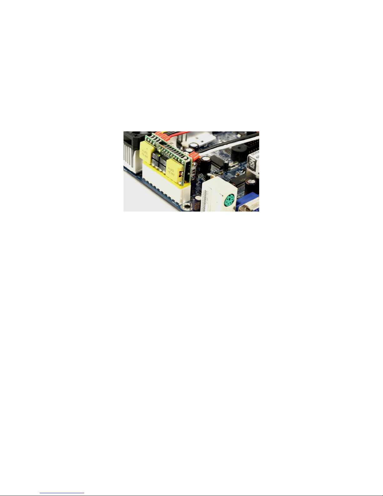
Fig 1.1 picoPSU-150-XT plugged into ATX connector.
2) Connect a 12 VDC power adapter (or any 12V source) to the DC-to-DC
connector, center pin / white wire is positive (+).
3) Turn on the PC using the motherboard ON/OFF switch
Typical configuration
The picoPSU-150-XT has been tested with all mini-ITX board under virtually any
disk/floppy/CDROM/PCI configuration. Additionally, the PICOPSU-150-XT can
power boards that require 4 pin 12V aux power connector to be used with
processors with TDP ranging from 35 to 65watts.
Removing the picoPSU-150-XT
In order to remove the picoPSU you must release the power connector latch and
then remove the unit. Gently lift the picoPSU out from the ATX connector, by
grabbing from the picoPSU PCB, not from components or the wire harness.
picoPSU-150-XT Quick Installation Guide Page 2
 Loading...