

Carter Products DELTA, DEL 14, DEL 14 HEX Series Manual
g u i d e c o n v e r s i o n k i t
D E L T A 1 4 ” B A N D
A Carter Products’ Guide Conversion Kit is one of the most costeffective performance enhancements you can buy for your band
saw. Whether you are using your saw on weekends, or multiple
saws in a manufacturing operation, Carter Guide Kits improve the
overall performance of any band saw. By controlling and guiding
the band saw blade you get greater accuracy, reduced friction, and
increased safety and blade life.
Carter Guides feature:
• Heavy-duty, industrial-grade engineering and construction
• Sealed ball bearing design for greater accuracy and durability
• Exceptionally low friction means cooler running blades and
longer blade life
• No wear on contact surfaces eliminates the need for
constant blade adjustments common with block guides
• Thrust support bearing at the rear of the guide
establishes low-friction contact on all blade surfaces
Guides are a major key to band saw performance.
Blade guides prevent the blade from moving out of
position when cutting. This is particularly critical in
resawing. Inadequate guiding under resaw stress will
result in inconsistent lumber thickness and substandard
parts.
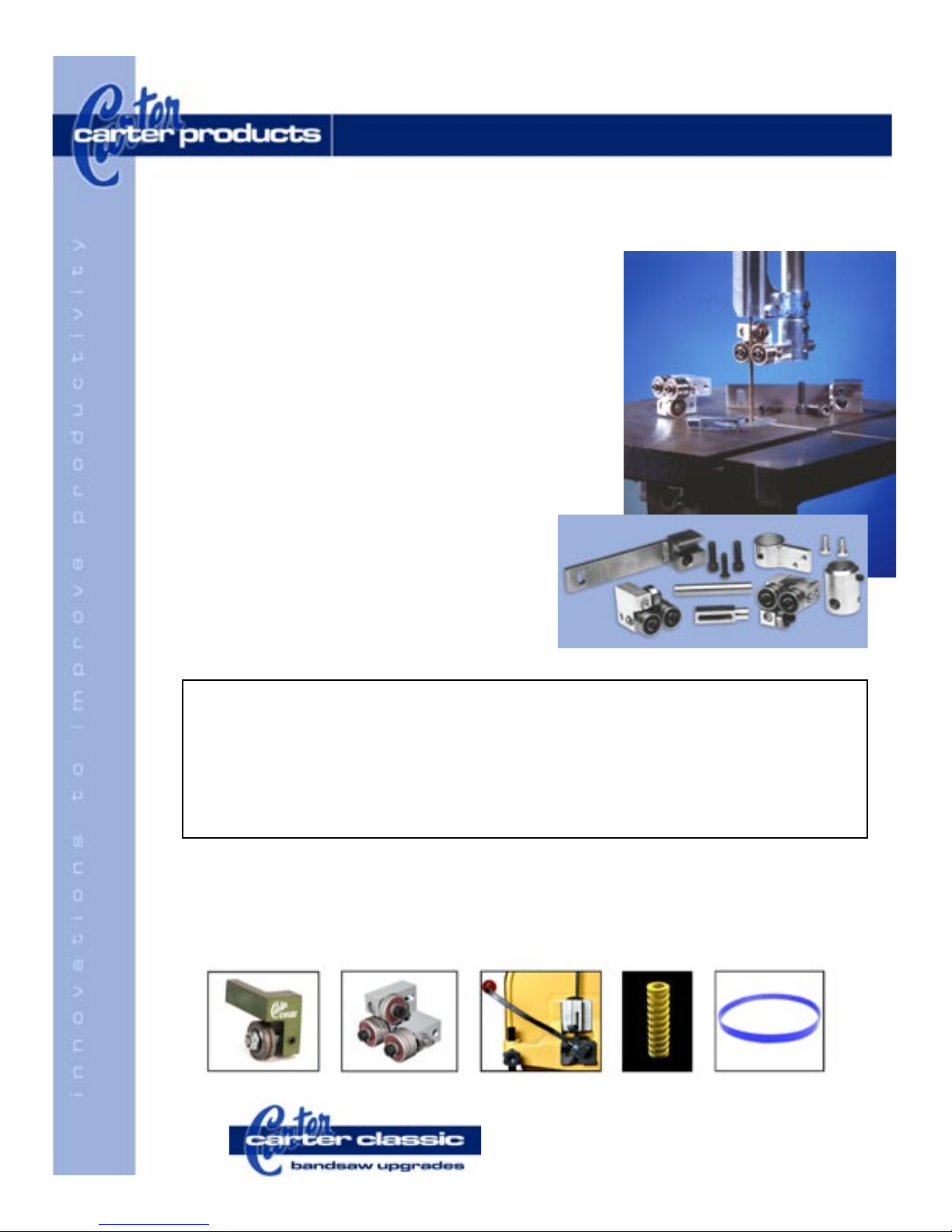
Delta 14” Kit • With round upper guide post • Carter Part #DEL 14
Delta 14” Kit • With hexagonal guide post • Carter Part #DEL 14 HEX
• 1 - Upper guide assembly (#2300)
• 1- Upper guide mounting bracket
• 1 - Upper mounting stud
• 1 - Upper guard and mountint bracket
• 2 - 5/16”-18 lower bracket mounting screws
Installation instructions on reverse
• 1 - Lower guide (#2300RH)
• 1- Lower guide mounting bracket
• 1 - Lower mounting stud
• 2 - 1/4”-20 guard mounting screw
• 1 - 1/4”-28 Lower stud mounting
Carter offers these fine band saw upgrades:
• Carter Sta bili zers
• Carter Band Saw Guide Conversion Kits
• Carter Quick Release Blade Tension Handles
• Cobra Coil Blade Tension Springs
• Carter Rubber and Urethane Bandsaw Tires
®
2871 Northridge Dr. NW • Grand Rapids, MI 49544
Phone: 888.622.7837 • Fax: 616.647.3387
E-mail: sales@carterproducts.com
Order online: www.carterproducts.com
CAUTION: DISCONNECT ALL ELECTRICAL POWER BEFORE BEGINNING INSTALLATION
i n s t a l l a t i o n i n s t r u c t i o n s
D E L T A 1 4 ” B A N D S A W S
Upper Guide Installation • Standard Kit
1) Remove existing upper guide and guard completely
2) Slide the guard bracket up over the vertical guide post and fasten in place
with set screws provided
4) Attach the upper guide bracket and guide as shown
5) Adjust the upper guide as detailed below
6) Attach the included guard to the guard bracket and position the assembly
down near the guide bracket
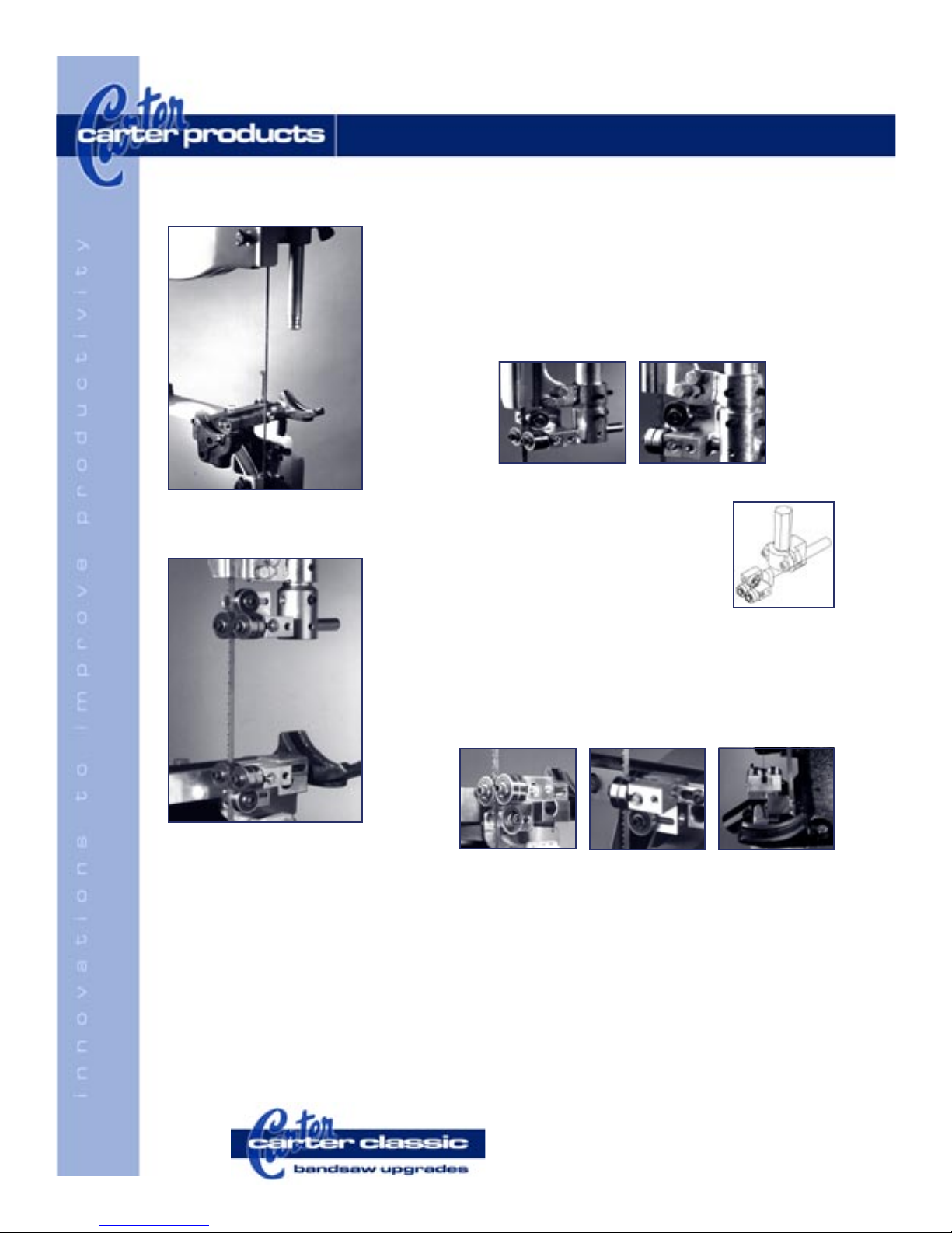
Delta band saw with table and
original guides removed
1) Remove upper guide and attachments
completely
2) Use two-piece cast aluminum clamp to attach
upper guide - as shown at right
3) Adjust upper guide per instructions below
4) Use included guard and guard bracket to
replace existing guard unit.
Lower Guide Installation • Both Kits
Upper Guide Installation • Hex Kit
1) Remove lower guide and attachments completely
2) Attach the lower guide bracket to the screw bosses in the saw frame using
the 5/16” bolts provided
3) Attach the lower guide/mounting stud to the lower bracket using the 1/4”28 screw provided
4) Adjust the lower guide as detailed in the instructions below
Jet band saw with new guides
attached
Guide Adjustment Instructions
1) CAUTION: DISCONNECT ALL ELECTRICAL
POWER BEFORE ADJUSTING BAND SAW
GUIDES
2) Each bearing assembly can be adjusted by
loosening the socket head cap screw through
the center of the bearing. Slide the bearing
assembly sideways so that the bearing is a couple
of thousandths of an inch - about the thickness of a
sheet of paper - away from the blade. Then lock the
bearing assembly in place by retightening the socket
cap screw securely. This should be done for both the
side bearings and the back-up bearing.
3) The lower thrust wheel should be adjusted by
loosening the locking set screw and sliding the shaft
forward or backward until the back of the blade is just
a couple of thousandths of an inch ahead of the top
surface of the thrust wheel. Lock the thrust wheel in
place by retightening the set screw.
4) Both the upper and lower guide assemblies should
be moved forward until the front edge of the side
support bearings lie just behind the gullet of the teeth
of the blade.
2871 Northridge Dr. NW • Grand Rapids, MI 49544
Phone: 888.622.7837 • Fax: 616.647.3387
E-mail: sales@carterproducts.com
Order online: www.carterproducts.com
 Loading...