

Page 1
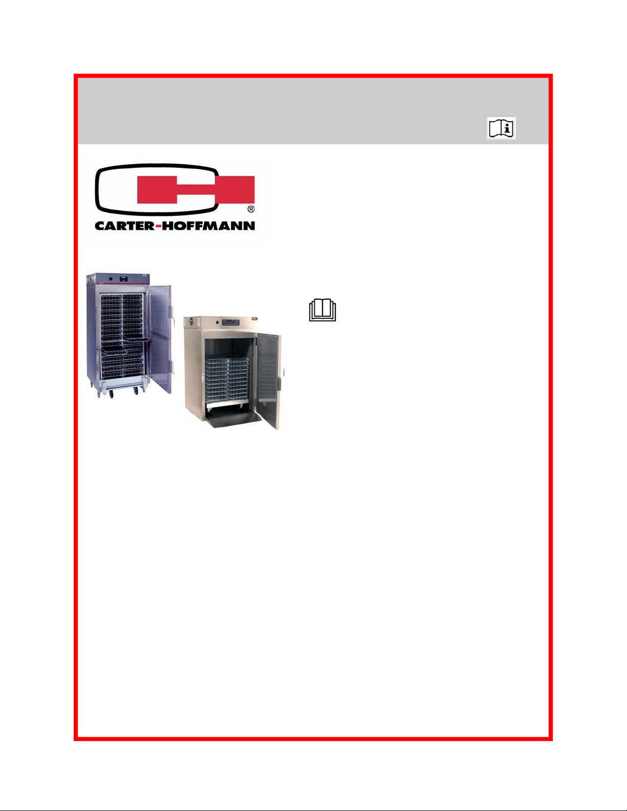
RTB Series RETHERMALIZATION CABINETS
MODELS: RTB10, RTB16, RTB34, RTB341, RTB281
OWNERS / OPERATORS MANUAL
MANUFACTURED BY:
CARTER-HOFFMANN
1551 McCormick Avenue
Mundelein, IL 60060 USA
Phone: 847-362-5500
Toll Free: 800-323-9793
Fax: 847-367-8981
Email: service@carter-hoffmann.com
READ THIS MANUAL COMPLETELY
BEFORE OPERATING THIS APPLIANCE
IMPORTANT: DO NOT DISCARD THIS MANUAL
This manual is considered to be part of the appliance and is to
be given to the OWNER, MANAGER, or to the person responsible for training operators of this appliance.
RTB341
RTB281
THIS MANUAL IS TO BE UNDERSTOOD BY ALL PERSONS
USING OR INSTALLING THIS APPLIANCE.
Contact Carter-Hoffmann if you have questions regarding installation, operation or maintenance of this equipment.
SAFETY INSTRUCTIONS…….………………………….. 2
INTRODUCTION AND SPECIFICATIONS…………...… 3
UNPACKING, INSPECTION & INSTALLATION……..… 4
INSTALLATION & START UP……………………………. 5
CONTROLLER FEATURES……………………………… 6-7
DAILY OPERATION……………………….………………. 8
CONTROLLER PROGRAMMING INFORMATIO N…….. 9-10
END-USER PROGRAMMING PATH 1724……………… 11-13
MANAGER PROGRAMMING PATH 3228..…………….. 14-20
DAILY CLEANING PROCEDURE………………………… 21-22
TROUBLESHOOTING GUIDE……………………………. 23
SERVICE EXPECTATIONS………….………….……...... 24
WARRANTY STATEMENT……………………....……….. 25
Printed in
The United States of America
TABLE OF CONTENTS
All Rights Reserved
Part Number: 18400-3155
Rev: KBA040111
Page 2

SAFETY PRECAUTIONS
WARNING: ELECTRIC SHOCK HAZARD
WARNING
All service requiring access to non-insulated components must be performed by
qualified service personnel. Failure to heed this warning may result in severe
electric shock.
CAUTION: ELECTRIC SHOCK HAZARD
Disconnect this appliance from electrical power before performing any
maintenance or service.
CAUTION: BURN HAZARD
Exposed metal surfaces can be hot to the touch and may cause burns.
IMPORTANT SAFETY INSTRUCTIONS
When using electrical appliances basic safety precautions should be followed, including the following:
1) Be familiar with the appliance use, limitations and associated restrictions. Operating instructions must
be read and understood by all persons using or installing this appliance.
2) This appliance must be grounded. Connect only to properly grounded outlet.
3) Use this appliance only for its intended purpose as described in the manual.
a. This equipment is specifically designed to hold pre-cooked food at temperature.
b.
c. This equipment is not designed for industrial or laboratory use.
4) Cleanliness of this appliance and its accessories is essential to good sanitation.
This equipment is intended for use in commercial establishments only.
5) DO NOT submerge this applia nce in water. This appliance is not jet stream approved. DO NOT direct
water jet or steam jet at this appliance, or at any control panel or wiring. DO NOT splash or pour water
on, in or over any controls, control panel or wiring. DO NOT use corrosive chemicals or vapors in this
appliance.
6) DO NOT store this appliance outdoors. DO NOT use this product near water – for example,
near a kitchen sink, in a wet basement, or near a swimming pool, or similar environment.
7) DO NOT operate this appliance if it has a damaged cord or plug, if it is not working properly, or if it has
been damaged or dropped. Do not immerse cord or plug in water, keep cord away from heated
surfaces, and do not let cord hang over edge of table or counter.
8) DO NOT cover or block any openings on the appliance.
9) Only qualified service personnel should service this appliance.
NOTE: This equipment has been designed and manufactured to meet all applicable health and
safety codes and will give years of dependable service if used properly. All cabinets should be
thoroughly cleaned before using.
NOTE:
illustrations and/or adjustment procedures, is intended for use by qualified technical personnel and is
subject to change without notice.
The technical content of this manual, including any wiring diagrams, schem atics, parts breakdown
2
Page 3
Carter-Hoffmann Series RTB Rethermalization cabinets are designed to uniformly rethermal ize individually pre-packaged menu items or individual meal trays in baskets.
INTRODUCTION
This equipment manual will provide you with basic information to safely install and operate this piece
of equipment. Should you encounter any difficulties, have any questions, or require any assistance,
please contact Carter-Hoffmann’s Technical Service department di rectly, at:
Telephone 800-323-9793 (toll-free) 847-362-5500
Fax 847-367-8981
Email service@carter-hoffmann.com.
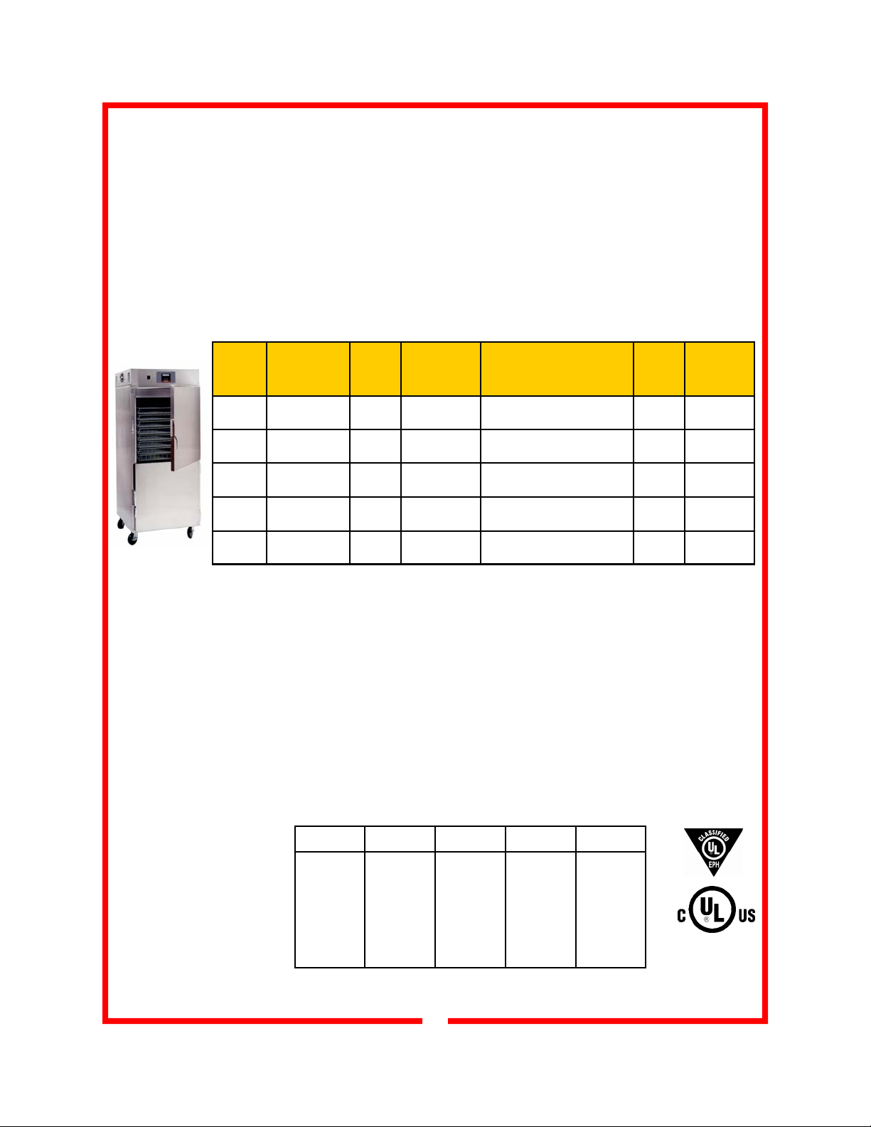
PRODUCT SPECIFICATIONS
RTB34
Model
Number
RTB10
RTB16 16 3
RTB34 34 3
RTB341 32
RTB281 28
Basket
Capacity*
13-3/8” x 25-7/8”
10 3
(on roll-in dolly) 3 (76)
(on roll-in dolly)
Basket
Spacing
Baskets
(76)
(76)
(76)
nest
Inside Working
Height
in (mm)
14-5/8
(371)
23-5/8
(600)
53-3/8
(1356)
58
(1473)
34-7/16
(875(
Overall Dimensions
Height Depth Width
in (mm)
39-1/4 35 33-1/8
(997) (889) (842) 5 (127)
48-1/4 35 33-1/8
(1226) (889) (842) 5 (127)
77-3/4 35 33-1/8
(1975) (889) (842) 5 (127)
78-1/2 35-5/8 35-3/8
(1994) (905) (899)
53-3/16 36-1/4 35-7/16
(1351) (921) (900)
Caster
Diameter
in (mm)
On legs 500
N/A 450
Class 100
Shipping
Weight
lbs (kg)
270
(123)
400
(181)
525
(238)
(227)
(205)
Construction...All Stainless steel double panel insulated cabinet with tamper resistant fasteners, heavy-duty
strap hinges. Heavy-duty edge-mount latch with magnetic catch. High temperature silicone gasket mounted to
cabinet.
Controller...microprocessor-based controller allows the user to program and store up to ten pre-set retherm
menu cycles. Each menu contains four retherm/hold cycles. Each cycle can be easily programmed for a
unique time and temperature to optimize performance of the heatin g system. Once a menu is programmed,
the cycle is stored in the controller’s memory until a change is made.
Heating System...Heavy-duty stainless steel construction. Secured in-place with tamper resistant fasters;
removable with tools. Inconel-sheathed heating elements, dual cooling fans and thermally protected blower
motor with long-life bearings. Precision engineered interior cabinet baffle system.
Performance… Capable of heating from 70°F (21°C) to 200°F (90C) in 5 minutes with a differential of ± 2.5°F.
Recovery from 120°F (49°C) to 200°F (90°C) in one minute (performance based on empty cabinet)
Electrical Specifications*
Model Volts Phase kW Amps
RTB10 208 1 6 28
RTB16 208 1 9 44
RTB34 208 3 18 60
RTB341 208 3 18 60
RTB281 208 3 27 100
* Electrical specifications shown are typical for standard cabinets. Due to the often customized nature of this product line, i. e. cabinets built to consultant’s/
facility specifications, the electrical specifications on your particular cabinet may be different. Consult serial tag on rear of heating unit for electrical info.
3
Page 4
UNPACKING, INSPECTION & INSTALLATION
This appliance
should be
thoroughly
cleaned prior to use.
See the CLEANING
INSTRUCTIONS in
this manual.
NOTE: DO NOT discard
the carton or other packing materials until you
1. Remove the cabinet from shipping carton, ensuring that all packing
materials and protective plastic has been removed from the unit.
2. Inspect all components for completeness and condition.
3. If any freight damage is present, a freight claim must be filed immediately with the shipping company.
4. Freight damage is not covered under warranty.
5. Check to insure all components are included: cabinet, instruction
packet and additional accessories.
6. Read operation instructions completely.
have inspected the appliance for hidden damage
and checked it for proper
7. Appliance should be thoroughly cleaned before use. See CLEANING INSTRUCTIONS in this manual.
operation. Refer to
FREIGHT DAMAGE
CLAIM PROCEDURE
BELOW
FREIGHT DAMAGE PROCEDURE
NOTE: For your protection, please note that equipment in this shipment was carefully ins pected and packaged
by skilled personnel before leaving the factory. Upon acceptance of this shipment, the transportatio n company
assumes full responsibility for its safe delivery.
IF SHIPMENT ARRIVES DAMAGED:
1. VISIBLE LOSS OR DAMAGE: Be certain that any visible loss or damage is noted on the freight bill or
express receipt, and that the note of loss or damage is signed by the delivery person.
2. FILE CLAIM FOR DAMAGE IMMEDIATELY
immediately.
3. CONCEALED DAMAGE: If damage is unnoticed unti l the merchandis e is unpack ed, notif y the transportation company or carrier immediately, and then file a “CONCEALED DAMAGE” claim with them. This
should be done within fifteen (15) days from the date the delivery was made to you. Be sure to retain the
container for inspection.
Carter-Hoffmann cannot assume liability for damage or loss incurred in transit, freight damage is not covered
under warranty. We will, however, at your request, supply you with the necessary docu ments to support your
claim.
: Regardless of the extent of damage. Contact your dealer
INSTALLATION LOCATION
For proper operation and maximum performance, locate the unit in an ambient air temperature of
70ºF (21ºC). For safe operation and maximum performance, locate the unit at least 4” from any wall
or combustible material.
Avoid placement in areas near exhaust fans or where there are active air movements.
Do not locate this unit under an overhead ventilation system or close to other cooking equipment.
Fumes and grease particles can be drawn by the cooling fans into the control comp artment of the
heater which should be avoided in order to assure top performance and longer life.
Unit must be on a solid level surface.
4
Page 5
INSTALLATION AND STARTUP
WARNING:
Risk of personal injury
Installation procedures must be
performed by a qualified technician
with full knowledge of all applicable
electrical codes. Failure could
result in personal injury and property damage.
IMPORTANT: See page 3
for power requirements
If necessary, contact a licensed
electrician to install an appropriate
electrical circuit with correct receptacle. Electrical requirements vary
by model number. Consult serial tag
on rear of heating unit for proper
electrical specifications.
DO NOT use an extension cord.
CAUTION:
Electrical Shock Hazard
T
he ground prong of the power
cord is part of a system designed to
protect you from electric shock in
the event of internal damage.
DO NOT cut off the large round
ground prong or twist a blade to fit
an existing receptacle.
GROUNDING INSTRUCTIONS
This appliance is equipped with a cord having a grounding wire with
a grounding plug which must be plugged into an outlet that is properly installed and grounded. In the event of an electrical short circuit, grounding reduces the risk of electric shock by providing an
escape wire for the electric current.
WARNING—Improper use of the grounding can result in a risk
of electric shock. Consult a qualified electrician or service agent if
the grounding instructions are not completely understood, or if doubt
exists as to whether the appliance is properly grounded.
To prevent an electrical shock hazard between the
appliance and other appliances or metal parts in close
vicinity, an equalization-bonding stud is provided. An
equalization bonding lead must be connected to this
stud and the other appliances/metal parts to provide
sufficient protection against potential difference. The
terminal is marked with the following symbol:
START UP
1. Prior to use, thoroughly clean the interior of the cabinet,
according to the instructions in this manual. Familiarize
yourself with the controls.
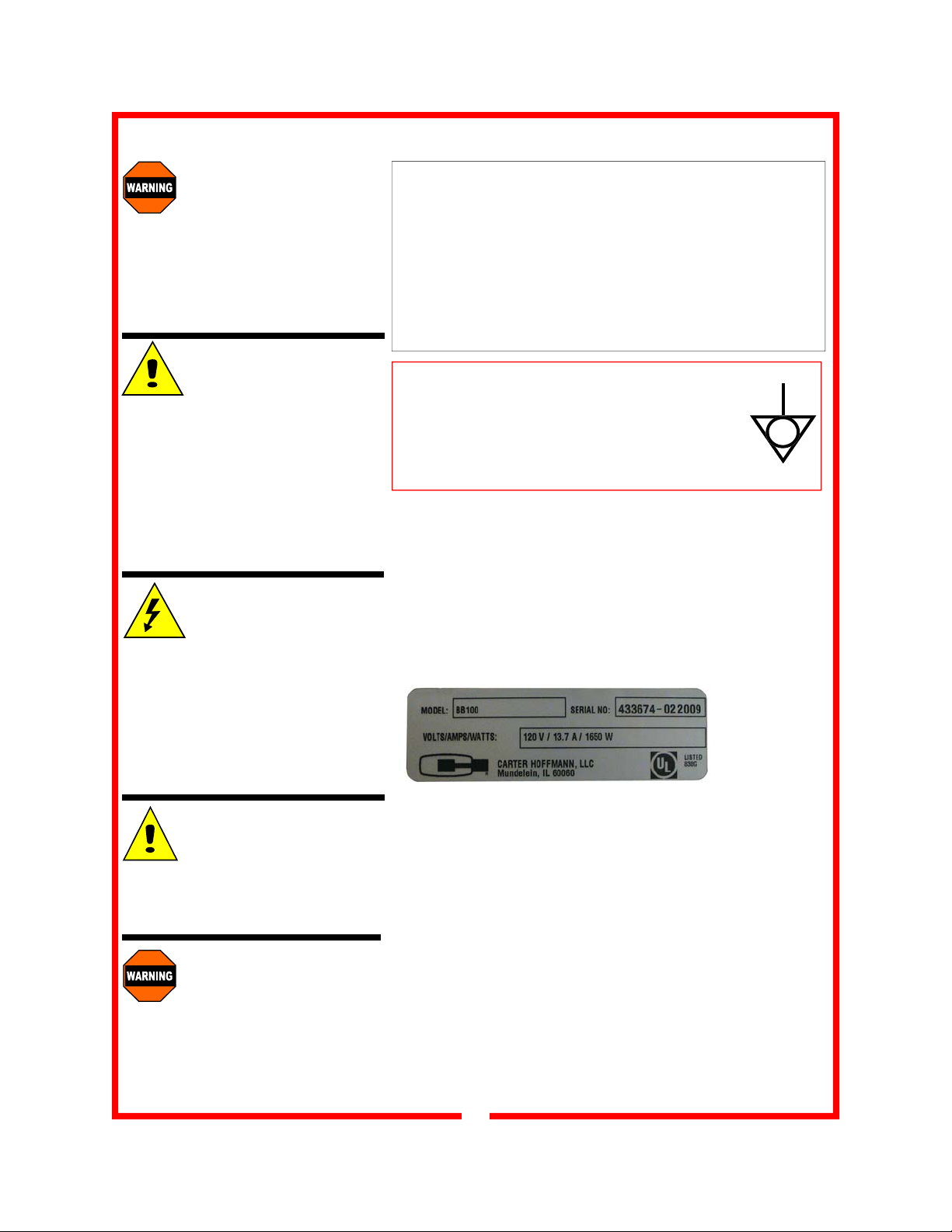
2. Plug the power cord of the cabinet into a grounded outlet
with a electrical service according to the electrical information provided on the serial tag located on the rear of
the cabinet heating unit. DO NOT MODIFY CORD PLUG.
Sample serial
tag
IMPORTANT:
Not under warranty
Damage to unit due to being
connected to the wrong voltage or
phase is NOT covered by warranty.
WARNING:
Risk of personal injury
Unit is not waterproof, to avoid
electrical shock, keep unit from being submerged in water. Do not
operate if unit has been in contact
with water.
3. Set POWER switch to the “ON” position.
4. Do not load product into the cabinet. Allow the heat to
remove any residual oils which may adhere to inside
metal surfaces. A slight emission of smoke is common
during the first few hours of operation.
5. Heat rethermalizer at 315° F for 35 minutes by pressing
Product Key number ten. The heat will remove any residual oils which may adhere to inside metal surfaces. To
cool down unit, press Product Key #10 again to turn off
cycle and open doors for about 15 minutes. A slight
emission of smoke is normal for the first few hours of operation.
6. Rethermalizer is ready for custom programming, if desired. See pages 9-20 for instructions.
5
Page 6
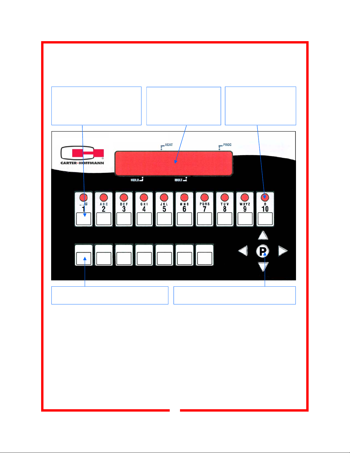
CONTROLLER FEATURES
On/Off rocker switch: located to the left of the control panel (not shown). Switch will illuminate
when cabinet is turned on.
Product Keys: press to start a
cook cycle; also used in program-
ming. Replaceable menu strip to
make menu changes quickly and
easily
8 Character LED Display:
displays programming and
cook cycle information
Indicator Lights: lit when
active cook cycle is in pro-
gramming mode
Feature Keys: used to access programming
functions and controller features
Programming Center: access programming
mode and change cooking parameters
FEATURE DETAILS
Fahrenheit of Celsius Temperature Display: the controller can be configured to display the
temperature in degrees Fahrenheit or Celsius; accessible through the system program mode.
Programmable Hold Times: Product Key hold times can be programmed to track product
quality through a specified holding period. Hold time countdown begins as soon as the cook
cycle is complete. The controller will sound an alarm when the product’s hold time has expired,
alerting the operator to discard the product.
6
Page 7

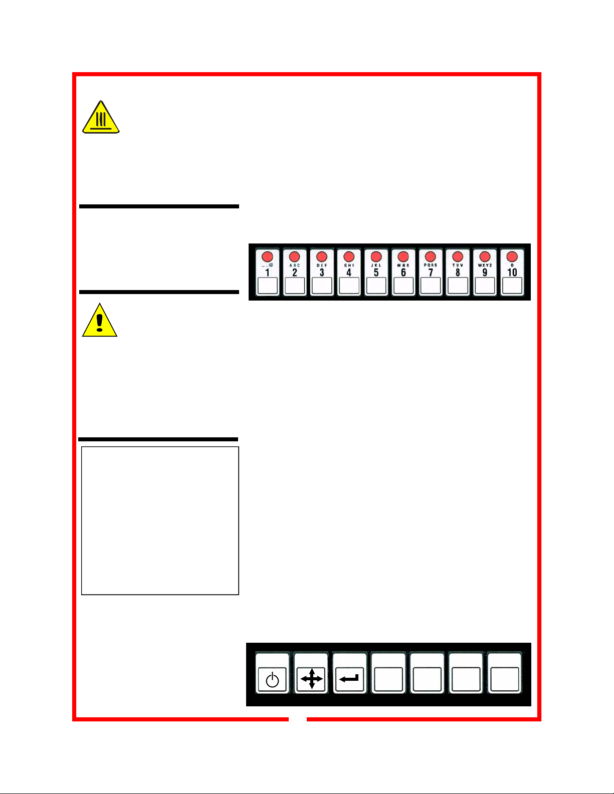
CONTROLLER FEATURE DETAILS
8 Character LED Display Indicator Lights Product Keys
Programming Center Feature Keys
Four-Stage Programming: each Product Key can be programmed to personalize your cook-
ing system with up to four cooking temperatures and up to ten cook times for a single cook cycle. With each Product Key, you can select a menu, start and stop a menu, scroll through programmed data (in Program Mode).
Programmable Stage Temperatures: cook temperatures for each stage on each Product
Key can be programmed. The temperature range is 200°F to 350°F (93.3°C to 172°C)
Programmable Stage Times: cook times for each Product Key can be programmed.
The controller is programmable in minutes (up to 99) and seconds (up to 59) and allows up
to ten stages per Product Key. Note: multiple cook starts are not allowed if a product key
has more than one stage programmed.
Programmable Fast.Flex™ Timing Mode: flex or straight timing can be configured for each
stage on each Product Key. To insure consistent, high-quality food product, flex time will adjust the actual cook time, taking into consideration the temperature variation due to load size,
initial product temperature, product moisture content, and other factors affecting the cook cycle.
If cooking by straight time, the controller will cook only for the specified time without adjusting
for these variances.
7
Page 8
DAILY OPERATION
WARNING:
HOT SURFACE
Inner surfaces of the unit will be
very hot during and after operation.
Avoid touching the cabinet when
loading or removing product.
Operating range:
Temperature: 200ºF-350ºF
(93.3°C to 172°C)
Time: up to 99 minutes, 59
seconds, for each stage on the
Product Key
CONTROLLER
OPERATING
ENVIRONMENT
The solid state components in the
controller are designed to operate
reliably in a temperature range up
to 158°F (70°C). Before installing,
verify that the ambient temperature where this product is located
does not exceed this temperature.
NOTE: To review and/or program
time and temperature settings for
each Product Key, refer to Pro-
gramming Instructions on
pages 10-20.
*NOTE: FAST.FLEX™ Timing
Mode may assist you with variable product features such as
temperature and load; see page
16 for programming instructions.
When cabinet is turned on, controller will default to Product
Key 1, indicated by illuminated indicator light. The display will
read “LOW”.
1) Turn power switch ON.
2) Load Product: For best retherm times, product must be
thawed or slacked prior to loading. Chilled or frozen food will
extend retherm time substantially*. Load baskets of food, beginning at the bottom of the cabinet and working up. If retherming less than a full load, arrange baskets so they are located
on the center shelves; this will ensure best air circulation and
even heating around the food.
3) Start a Cook Cycle: Press desired Product Key (1 through
10 to start a cook cycle. If the key is programmed, the correct
cooking time will be displayed and will immediately start to
count down in minutes and seconds. “DONE” will display
when the cook cycle has ended. Product is ready to be removed, but may stay in the cabinet in Hold Mode until served.
4) Respond to DONE Alarm: DONE alarm will sound at the
end of a completed cycle. Cancel the signal by pressing the
same Product Key used to start the cook cycle.
5) Stop a Cook Cycle: Press and hold an active Product Key
for 3 seconds. Timing will stop.
6) Holding Cycle: If the controller is programmed with holding
times, they will automatically start counting upon expiration of
the cooking cycle. When there are active hold times the HOLD
indicator light will be lit.
To view all active hold times, press and hold the HOLD Key.
Upon expiration, the timer will display “HOLD” and pulse with
an audible tone.
To cancel, press the HOLD Key.
ON/OFF SCAN
8
TEMP
TOGL CLEAR
HOLD
Page 9

CONTROLLER PROGRAMMING INSTRUCTIONS
Operating range:
Temperature: 200ºF-350ºF
(93.3°C to 172°C)
Time: up to 99 minutes, 59
seconds, for each stage on the
Product Key
CONTROLLER
OPERATING
ENVIRONMENT
The solid state components in the
controller are designed to operate
reliably in a temperature range up
to 158°F (70°C). Before installing,
verify that the ambient temperature where this product is located
does not exceed this temperature.
Operation Mode: When the power is turned “ON”, the controller will read LOW and the temperature of the cabinet displayed
in °F or °C. From the operation mode, a menu can be started
by pressing the appropriate Product Key. Note: the fan will be
ON in the operation mode.
NOTE: To view actual cabinet temperature, press the TEMP
TOGL CLEAR button. Press the button again to exit.
Controller Programming: Retherm cabinets may or may not
have been pre-programmed by the factory to end user specifications. If the factory has pre-programmed the controller, it
should be reviewed to ensure proper set-points prior to use.
If the controller has not been pre-programmed by the factory, it
will be programmed to the default menu settings listed on the
chart below.
If programming is needed, follow the Controller Programming
Instructions on pages 10 through 20. Use the programming
worksheet provided below to aid your controller programming.
Pre-Programmed Default Menu Settings
Control
Display
Time 0 Preheat Time 20 25 30 35 20 25 30 35 20 25
Preheat Preheat Set Point 200 210 220 230 240 250 265 285 300 315
Product Key
Description
Product
Key 1
Product
Key 2
Product
Key 3
Product
Key 4
Product
Key 5
Product
Key 6
Product
Key 7
Product
Key 8
Product
Key 9
Product
Key 10
Time 1 Cook 1 Time 20 15 10 5 20 15 10 5 20 15
Temp 1 Cook 1 Set Point 180 185 190 195 200 215 230 250 275 300
Time 2 Cook 2 Time 20 15 10 5 20 15 10 5 20 15
Temp 2 Cook 2 Set Point 190 200 210 220 230 240 250 280 285 305
Time 3 Hold Time 30 30 30 30 30 30 30 30 30 30
Hold Hold Set Point 170 170 170 170 170 170 170 170 170 170
Controller Programming Worksheet
Control
Display
Time 0 Preheat Time
Preheat Preheat Set Point
Time 1 Cook 1 Time
Temp 1 Cook 1 Set Point
Time 2 Cook 2 Time
Temp 2 Cook 2 Set Point
Time 3 Hold Time
Hold Hold Set Point
Product Key
Description
Product 1 Product 2 Product 3 Product 4 Product 5 Product 6 Product 7 Product 8 Product 9 Product
9
10
Page 10

CONTROLLER PROGRAMMING INSTRUCTIONS (Continued)
Operating range:
Temperature: 200ºF-350ºF
(93.3°C to 172°C)
Time: up to 99 minutes, 59
seconds, for each stage on the
Product Key
Product Keys: press to start
a cook cycle; also used in
programming. Replaceable
menu strip to make menu
changes quickly and easily
Programming Levels The controller is equipped with two levels of programming access:
End User Programming Path 1724 allows the end user to
program Menu Settings. Daily users of this cabinet should be
familiar with all aspects of Program Mode 1724. See pages
11-13 for Program Mode 1724 instructions.
Manager Programming Path 3228 allows the user to program parameters such as Machine Type, Duct Temperature,
Fahrenheit/Celcius, Temperature Minimum and Maximum and
Set Point Differential. It is advised that access to Program
Mode 3228 be known only to owners/operators and not daily
users of the product. See pages 14-20 for Program Mode
3228 instructions.
8 Character LED
Display:
displays programming & cook cycle
information
Indicator Lights:
lit when active cook
cycle is in program-
ming mode
Feature Keys: used to access
programming functions and
controller features
10
Programming Center: access
programming mode and change
cooking parameters
Page 11

CONTROLLER PROGRAMMING INSTRUCTIONS (Continued)
Operating range:
Temperature: 200ºF-350ºF
(93.3°C to 172°C)
Time: up to 99 minutes, 59
seconds, for each stage on the
Product Key
Programming Center Keys
LED Display
PROGRAMMING NOTES
Pressing the DOWN ARROW will
scroll through the entire sequence. If you wish to go back to
a particular parameter, press the
UP ARROW until the desired setting is reached.
To EXIT the Programming
Mode, scroll through the pro-
gramming choices until the display reads “SYSTEM”. Press UP
ARROW. The display will read
“EXIT”. Press “P” and you will
return to the Operating Mode.
If you discontinue programming
and leave the controller idle, it will
automatically exit the Programming Mode after two minutes.
END-USER PROGRAMMING PATH 1724
Program Path 1724 allows the end user to program up to ten
Menu Settings, one for each Product Key. Each Product Key
can be programmed for 4 stages in the Cook Cycle. This allows the user to vary the time and temperature in each stage
throughout the cooking cycle to achieve best product quality.
Stage 1: Pre-heat time
Pre-heat setpoint (Temperature setting)
Stage 2: Cook 1 Time
Cook 1 Setpoint (Temperature setting)
Stage 3: Cook 2 Time
Cook 2 Setpoint (Temperature setting)
Stage 4: Hold Time
Hold Setpoint (Temperature setting)
When scrolling through the Program Mode, the sequence of
programming will take you through programming all four program TIMES and then through all four program TEMPERATURES for the Product Key. The programming order scrolls as
such:
TIME 0 (Pre-heat time)
TIME 1 (Cook 1 time)
TIME 2 (Cook 2 time)
TIME 3 (Hold time)
PREHEAT (Pre-heat temperature)
COOK 1 (Cook 1 temperature setpoint)
COOK 2 (Cook 2 temperature setpoint)
HOLD (Hold temperature setpoint)
Pressing the DOWN ARROW will scroll through the entire sequence. If you wish to go back to a particular time or temperature, press the UP ARROW until the desired setting is
reached.
To access Program Mode 1724
press and hold “P”.
The display will read: “COUNTS”
Press the DOWN ARROW
11
Continued on next page
Page 12

CONTROLLER PROGRAMMING INSTRUCTIONS (Continued)
Operating range:
Temperature: 200ºF-350ºF
(93.3°C to 172°C)
Time: up to 99 minutes, 59
seconds, for each stage on the
Product Key
LED Display
The display will read: “PROGRAM”
Enter code “1724” using the Product Keys. As you type in
the numbers, they will appear as asterisks on the display.
Then, press “P”
The display will read: “RECIPE”
Press “P”
The display will read: “PRODUCT”
Select the Product Key (1 through 10) you wish to program
by pressing the product key.
TIME
PROGRAMMING
INSTRUCTIONS
Press “P”
The display will read: “ALL”
Press the DOWN ARROW button
The display will read: “TIME 0” (this is the PreHeat Time
setting) and then it will display the current time that has been
programmed.
Press the “TEMP TOGL CLEAR” key to clear the display; it
will revert to “:00”
TEMP
ON/OFF SCAN
TOGL CLEAR
HOLD
Continued on next page
12
Page 13

CONTROLLER PROGRAMMING INSTRUCTIONS (Continued)
Operating range:
Temperature: 200ºF-350ºF
(93.3°C to 172°C)
Time: up to 99 minutes, 59
seconds, for each stage on the
Product Key
LED Display
TEMPERATURE
PROGRAMMING
INSTRUCTIONS
Using the Product Keys, type in the time desired for the PREHEAT time in minutes and seconds, for example 25:30 is 25
minutes and 30 seconds. Use the #10 product key for the
number 0.
Press the DOWN ARROW button to scroll
through and repeat the above procedure for
TIME 1, TIME 2 and TIME 3
After scrolling through the TIME settings
and programming in your desired times,
continue to scroll by pressing DOWN AR-
ROW to enter programming for each of the
four TEMPERATURE settings
The display will read “TEMP”
Press “P”
The display will read “PREHEAT” and then the currently programmed temperature for the preheat cycle (for example 250°
F). Type in the desired temperature for the preheat cycle. Use
the #10 product key for the number 0.
Press the arrow DOWN ARROW button to
scroll through and repeat the procedure to
program temperatures for TEMP 1, TEMP 2
and HOLD cycles.
Display will read “TEMP 1”, “TEMP 2”, and “HOLD” followed
by the currently programmed temperature for each cycle.
Type in the desired temperature for each cycle as you scroll
through them.
After programming the “HOLD” temperature,
press the arrow down button twice (scrolling
past the “ALRMTIME” to get to the EXIT
display).
When the display reads “EXIT”, press “P” to
exit the Programming Mode.
13
Page 14

CONTROLLER PROGRAMMING INSTRUCTIONS (Continued)
Operating range:
Temperature: 200ºF-350ºF
(93.3°C to 172°C)
Time: up to 99 minutes, 59
seconds, for each stage on the
Product Key
Programming Center Keys
LED Display
PROGRAMMING NOTES
Once in Programming Path 3228,
pressing “DOWN ARROW” or
“P” will scroll through the entire
sequence of parameters. If you
wish to go back to a particular
parameter, press the UP AR-
ROW until the desired setting is
reached.
To EXIT the Programming
Mode, scroll through the pro-
gramming choices until the display reads “SYSTEM”. Press UP
ARROW. The display will read
“EXIT”. Press “P” and you will
return to the Operating Mode.
If you discontinue programming
and leave the controller idle, it will
automatically exit the Programming Mode after two minutes.
MANAGER PROGRAMMING PATH 3228
Program Path 3288 is a deeper level programming mode that
should be used by the manager only. In most cases, this
mode would be used infrequently, if at all. The sequence of
parameters that may be programmed in Program Path 3228
is:
MACHINE (you will not ever need to change this parameter)
APPLIANC (you will not ever need to change this parameter)
GD BAND Allows changes to the heating duct temperature;
maximum temperature is 400°F
TIMING Allows you program standard or FAST.FLEX™ timing
mode
COOKUNIT Allows you to change the timing to hours and min-
utes, or minutes and seconds
TONE VOL Allows you to change the volume of the controller
alarm
TEMP UNIT Allows you to change the temperature scale to
Fahrenheit or Celsius
RANGE L 1 Allows you to change the lower programmable
menu temperature; minimum 32°F
RANGE L 2 Allows you to change the upper programmable
menu temperature; maximum 350°F
HYS 1 Allows you to set the lower temperature differential; this
tells the machine when the temperature drops a certain number of degrees below the temperature setpoint to turn the
heating element on. Preprogrammed differential is 5°; In most
cases this is sufficient for effective machine performance
HYS 2 Allows you to set the upper temperature differential;
this tells the machine when the temperature goes above the
set point temperature to turn the heating element off. Preprogrammed differential is 5°; In most cases this is sufficient for
effective machine performance
RANGEL 2 (you will not ever need to change this parameter)
RANGEH 2 (you will not ever need to change this parameter)
HYSL 2 (you will not ever need to change this parameter)
HYSH 2 (you will not ever need to change this parameter)
14
Continued on next page
Page 15

CONTROLLER PROGRAMMING INSTRUCTIONS (Continued)
Operating range:
Temperature: 200ºF-350ºF
(93.3°C to 172°C)
Time: up to 99 minutes, 59
seconds, for each stage on the
Product Key
Programming Center Keys
LED Display
*PROGRAMMING NOTE
You may also enter Programming Mode 1724 by scrolling to
“RECIPE” from the “SYSTEM”
screen using the DOWN ARROW
button. You may then program
the menu settings for Product
Keys 1 through 10, according to
the instructions on pages 12-13.
Scrolling past “RECIPE” at this
level will take you to
“DIAGNOST”, “OFFSET”, SCK
ADDR” and “EXIT” in that order.
“DIAGNOST” “OFFSET” and
“SCK ADDR” are to be used by
service technicians only. Do not
change any of the settings in
these parameters.
To exit, scroll until the screen
reads “EXIT” by using the UP or
DOWN ARROW buttons, and
then press “P”.
To access Program Mode 3228
press and hold “P”.
The display will read: “COUNTS”
Press the DOWN ARROW
The display will read: “PROGRAM”
Enter code “3228” using the Product Keys. As you type in
the numbers, they will appear as asterisks on the display.
*The display will read: “SYSTEM”
Press “P”
The display will read “MACHINE”
Skip this program by pressing the DOWN ARROW button
Press the DOWN ARROW button
The display will read “APPLIANC”
Skip this program by pressing the DOWN ARROW button
Press the DOWN ARROW button
15
Continued on next page
Page 16

CONTROLLER PROGRAMMING INSTRUCTIONS (Continued)
Operating range:
Temperature: 200ºF-350ºF
(93.3°C to 172°C)
Time: up to 99 minutes, 59
seconds, for each stage on the
Product Key
Programming Center Keys
LED Display
TO CHANGE THE HEATER DUCT TEMPERATURE, scroll
using the DOWN ARROW until the display reads “GD BAND”
If you wish to change the heating duct temperature
press “P”.
and the display will read the current duct temperature.
To change the temperature, press the TEMP TOGL
CLEAR button. The display will read 0°F.
TEMP
ON/OFF SCAN
TOGL CLEAR
HOLD
Type in a the desired duct temperature using the Product Keys (use 10 for the number 0). The maximum num-
ber that may be entered is 400°F.
ABOUT FAST.FLEX™ OR
STRAIGHT TIMING MODE
Flex or straight timing can be configured for each stage on each
Product Key. The advantage of the
FAST.FLEX mode is to insure consistent, high-quality food product.
FAST.FLEX will adjust the actual
cook time, taking into consideration the temperature variation due
to load size, initial product temperature, product moisture content, and other factors affecting the
cook cycle. However, using
FAST.FLEX mode may alter the
time expected to finish the cooking
cycle. If cooking by straight time,
the controller will cook only for the
specified time without adjusting for
these variances.
After typing in your desired temperature, press “P” to return
to the main 3228 Program Sequence. The display will read
“TIMING”.
TO CHANGE THE TIMING MODE, scroll by pressing DOWN
ARROW until the display reads “TIMING”
If you wish to change the timing from standard cooking
mode to FAST.FLEX™ mode or vice versa
press RIGHT ARROW or LEFT ARROW
to alternate between ‘FLEX” and
“STRAIGHT”
When your desired timing appears on the display, press
“P” to select and save your choice.
The display will read “COOKUNIT”
Continued on next page
16
Page 17

CONTROLLER PROGRAMMING INSTRUCTIONS (Continued)
Operating range:
Temperature: 200ºF-350ºF
(93.3°C to 172°C)
Time: up to 99 minutes, 59
seconds, for each stage on the
Product Key
Programming Center Keys
LED Display
PROGRAMMING NOTES
Once in Programming Path 3228,
pressing “DOWN ARROW” or
“P” will scroll through the entire
sequence of parameters. If you
wish to go back to a particular
parameter, press the UP AR-
ROW until the desired setting is
reached.
To EXIT the Programming
Mode, scroll through the pro-
gramming choices until the display reads “SYSTEM”. Press UP
ARROW. The display will read
“EXIT”. Press “P” and you will
return to the Operating Mode.
If you discontinue programming
and leave the controller idle, it will
automatically exit the Programming Mode after two minutes.
TO CHANGE THE TIMER COUNTDOWN from minutes and
seconds to hours and minutes or vice versa, scroll using the
DOWN ARROW until the display reads “COOKUNIT”
Press LEFT ARROW or RIGHT ARROW
to select “HH:MM” (hours and minutes) or
“MM:SS” (minutes and seconds) for the
timer countdown
press “P”.
The display will read “TONE VOL”
TO CHANGE THE TONE VOLUME of the controller, scroll
using the DOWN ARROW until the display reads “TONE
VOL”
Press LEFT ARROW or RIGHT ARROW
to select your desired volume; tone
ranges from 1 (softest) to 4 (loudest).
When you reach the desired volume
press “P”.
The display will read “TEMP UNIT”
TO CHANGE THE TEMPERATURE SCALE of the controller
from Fahrenheit to Celsius or vice versa, scroll using the
DOWN ARROW until the display reads “TEMP UNIT”
Press LEFT ARROW or RIGHT ARROW
to select your desired scale (controller will
read “F” or “C”). When you reach the
desired scale
press “P”.
The display will read “RANGE L 1”
17
Continued on next page
Page 18

CONTROLLER PROGRAMMING INSTRUCTIONS (Continued)
Operating range:
Temperature: 200ºF-350ºF
(93.3°C to 172°C)
Time: up to 99 minutes, 59
seconds, for each stage on the
Product Key
Programming Center Keys
LED Display
PROGRAMMING NOTES
Once in Programming Path 3228,
pressing “DOWN ARROW” or
“P” will scroll through the entire
sequence of parameters. If you
wish to go back to a particular
parameter, press the UP AR-
ROW until the desired setting is
reached.
To EXIT the Programming
Mode, scroll through the pro-
gramming choices until the display reads “SYSTEM”. Press UP
ARROW. The display will read
“EXIT”. Press “P” and you will
return to the Operating Mode.
If you discontinue programming
and leave the controller idle, it will
automatically exit the Programming Mode after two minutes.
TO CHANGE THE LOW TEMPERATURE RANGE of the controller, scroll using the DOWN ARROW until the display reads
“RANGEL 1” and then the currently stored LOW temperature
setting (i.e. 32°F). Press “TEMP TOGL CLEAR” button to
clear the temperature setting. The display will read “0°F”
ON/OFF SCAN
TOGL CLEAR
HOLD
TEMP
Using the Product Keys, type in the new desired LOW temperature setting (Use the number 10 for 0). NOTE: 32°F is the
lowest possible setting that can be used.
press “P”.
The display will read “RANGEH 1”
TO CHANGE THE HIGH TEMPERATURE RANGE of the
controller, scroll using the DOWN ARROW until the display
reads “RANGEH 1” and then the currently stored HIGH temperature setting (i.e. 350°F). Press “TEMP TOGL CLEAR”
button to clear the temperature setting. The display will read
“0°F”
TEMP
ON/OFF SCAN
TOGL CLEAR
HOLD
Using the Product Keys, type in the new desired HIGH temperature setting (Use the number 10 for 0). NOTE: 350°F is
the highest possible setting that can be used.
press “P”.
The display will read “HYS L 1”
18
Continued on next page
Page 19

CONTROLLER PROGRAMMING INSTRUCTIONS (Continued)
Operating range:
Temperature: 200ºF-350ºF
(93.3°C to 172°C)
Time: up to 99 minutes, 59
seconds, for each stage on the
Product Key
Programming Center Keys
LED Display
PROGRAMMING NOTES
Once in Programming Path 3228,
pressing “DOWN ARROW” or
“P” will scroll through the entire
sequence of parameters. If you
wish to go back to a particular
parameter, press the UP AR-
ROW until the desired setting is
reached.
To EXIT the Programming
Mode, scroll through the pro-
gramming choices by pressing
“P” until the display reads
“SYSTEM”. Press UP ARROW.
The display will read “EXIT”.
Press “P” and you will return to
the Operating Mode.
If you discontinue programming
and leave the controller idle, it will
automatically exit the Programming Mode after two minutes.
TO CHANGE THE LOWER TEMPERATURE DIFFERENTIAL
of the controller, scroll using the DOWN ARROW until the display reads “HYSL 1” and then the currently stored lower differential temperature setting (i.e. 5°F). Press “TEMP TOGL
CLEAR” button to clear the temperature setting. The display
will read “0°F”
ON/OFF SCAN
TOGL CLEAR
HOLD
TEMP
Using the Product Keys, type in the new desired low temperature setting (Use the number 10 for 0).
press “P”.
The display will read “HYSH 1”
TO CHANGE THE UPPER TEMPERATURE DIFFERENTIAL
of the controller, scroll using the DOWN ARROW until the display reads “HYSH 1” and then the currently stored upper differential temperature setting (i.e. 5°F). Press “TEMP TOGL
CLEAR” button to clear the temperature setting. The display
will read “0°F”
ON/OFF SCAN
TOGL CLEAR
HOLD
TEMP
Using the Product Keys, type in the new desired upper temperature setting (Use the number 10 for 0).
19
press “P”.
Continued on next page
Page 20

CONTROLLER PROGRAMMING INSTRUCTIONS (Continued)
Operating range:
Temperature: 200ºF-350ºF
(93.3°C to 172°C)
Time: up to 99 minutes, 59
seconds, for each stage on the
Product Key
Programming Center Keys
LED Display
PROGRAMMING NOTES
Once in Programming Path 3228,
pressing “DOWN ARROW” or
“P” will scroll through the entire
sequence of parameters. If you
wish to go back to a particular
parameter, press the UP AR-
ROW until the desired setting is
reached.
To EXIT the Programming
Mode, scroll through the pro-
gramming choices until the display reads “SYSTEM”. Press UP
ARROW. The display will read
“EXIT”. Press “P” and you will
return to the Operating Mode.
If you discontinue programming
and leave the controller idle, it will
automatically exit the Programming Mode after two minutes.
It is not necessary to program the rest of the parameters in
the sequence. They are:
The display will read “RANGEL 2”
Skip this parameter by pressing “P”
The display will read “RANGEH 2”
Skip this parameter by pressing “P”
The display will read “HYSL 2”
Skip this parameter by pressing “P”
The display will read “HYSH 2”
Skip this parameter by pressing “P”
The controller will return to the beginning of the sequence
and the display will read “MACHINE”
To EXIT PROGRAMMING MODE 3228
Scroll through the programming sequence using the DOWN
ARROW or UP ARROW until the display reads “MACHINE”
Press UP ARROW
The display will read “SYSTEM”
Press UP ARROW
The display will read “EXIT”
press “P”.
The controller is now out of Program Mode and in Operating
Mode.
The controller will also exit Programming Mode if left idle for
more than two minutes.
20
Page 21

DAILY CLEANING PROCEDURES
CAUTION:
ELECTRIC SHOCK
HAZARD
Disconnect appliance from
electric power before cleaning.
NOTE: When the power is
turned off, the cooling fans will
continue to operate until the
heater compartment cools
down. DO NOT unplug the
cabinet until the cooling fans
turn off.
CAUTION:
HOT SURFACE
Exposed surfaces can
be hot to the touch and may
cause burns. Allow appliance
to cool before cleaning.
IMPORTANT:
DO NOT spill or pour
water into controls,
control panel or wiring. Water
damage is not covered by warranty.
CAUTION
Beware of sharp
edges with sheet
metal during cleaning process.
:
1. After all food products have been removed from the cabinet,
turn the power switch to “OFF” and allow the cabinet to cool.
2. Unplug the unit prior to any cleaning.
3. Remove the side heat duct and rack assemblies. Simply lift
up and pull out. They may be hand washed or run through an
automatic washer. Clean the inside of the unit as well as the
removed parts. Reinstall when all parts are dry and clean.
4. To clean stainless steel surfaces, use only cleansers, detergents, degreasers or sanitizers that are certified to be
“chloride-free” and “phosphate-free.” Use these products only
in recommended concentrations. DO NOT exceed recommended concentrations or mixing ratios. After cleaning and
sanitizing, rinse all exposed surfaces thoroughly with large
amounts of clean, clear water. Wipe off any standing liquid or
residue from all surfaces, corners and near edges.
5. Inspect and clean the areas where there are vents or filters,
making sure no water gets into the internal controls or electrical areas of the cabinet. CAUTION: When using solvents, it is
essential that proper precautionary measure be observed.
Refer to solvent manufacturer’s instructions. Use of direct
steam/hot water at temperatures above 190°F may result in
bubbling or loosening of the control panel.
6. Plastic control panel should be washed with a clean damp
cloth and chlorine-free detergent. Rinse thoroughly with clean
damp cloth and allow to dry. Do not use abrasive cleaners,
waxes, car polish, or substances containing strong aromatic
solvents or alcohol.
CAUTION: Cleansers, detergents, degreasers, sanitizers, or bleaching agents that contain chlorides or phosphates will cause permanent damage to stainless steel products. The damage appears
as pits, eruptions, voids, small holes, severe discoloration or dulling of the metal finish.
Water with high chloride content can also damage stainless steel. If unsure of your water quality, we recommend you have it tested. THIS DAMAGE IS PERMANENT, COSTLY TO REPAIR, AND IS NOT COVERED
BY THE WARRANTY.
SEE NEXT PAGE FOR RECOMMENDED TIPS FOR CLEANING STAINLESS STEEL
21
Page 22

CABINET MAINTENANCE
CAUTION:
Never move cart
unless all doors are
securely closed. Serious
damage to hinges and doors
may result if bumped into tables, walls, or other equipment when doors are open.
CASTERS
Your cabinet may be equipped with casters or legs. If your cabinet
has casters they may be easily lubricated with a grease gun. Lubricate bearings at least once every six months. Lubrication will be
required every one to two weeks if carts are cleaned with hot water
or steam cleaning system. NOTE: Casters with special DelrinTM
bearings are recommended for frequent cart wash with steam
cleaning systems or high pressure hose.
LATCHES
Check frequently to insure that all door latches are secure.
Latches may become “sticky” due to residue buildup from daily use
and cleaning procedures. Lubricate latches once every six months
or when needed with WD40, silicone spray, graphite or other commercial lubricant for stainless steel products. Do not use oil.
HINGES
Your cart doors and hinges have been factory aligned to assure
positive latching and smooth action. If doors are removed for
cleaning, we recommend that they be put back on the same cart to
assure the best
possible alignment and operation.
DOORS
Never tip carts forward on open doors to drain water during or after
washing. This can cause serious damage to hinges, doors and
latches.
RECOMMENDED TIPS FOR CLEANING STAINLESS STEEL
Purpose Frequency Cleaning Agent Method of Application
Routine Daily Soap, ammonia Sponge with cloth, rinse with clear water
detergent and water and wipe dry.
Smears/ As Stainless steel cleaner Rub with soft cloth as directed on package.
Fingerprints needed or similar products Rub in direction of grain of stainless steel.
Do not use on vinyl trim.
Stubborn Daily Any chloride-free Apply with damp sponge or cloth. Rub in
spots and as or direction of grain of stainless steel. Rinse
stains needed phosphate-free thoroughly, especially if cleaner contains
cleaner chlorine bleach, do not use on vinyl trim.
Hard water Daily Vinegar Swab with cloth.
spots as needed Rinse with water and wipe dry.
22
Page 23

TROUBLESHOOTING GUIDE
PROBLEM PROBABLE CAUSE CORRECTIVE ACTION
NO POWER Power cord not plugged in Plug in power cord to proper re-
ceptacle
ON/OFF Switch OFF Turn ON/OFF Switch ON
Main circuit breaker tripped Check and reset breaker
Line fuse blown Correct cause of fuse failure and
replace fuses
Defective 24VAC transformer Replace transformer. Replace
controller
CABINET FAILS TO HEAT
(Start/Stop button pressed. Oven
will not heat. Blower fan runs)
CABINET FAILS TO HEAT
(Heat indicator comes on. All
other displays normal)
CABINET FAILS TO HEAT
(Temperature lamp comes on.
All other displays normal)
OVEN NOT HEATING
NORMALLY
CONTROLLER
INOPERATIVE
OR ERRATIC
AIR TEMP PROBE FAILURE
(Air probe malfunctions)
Door not fully closed Close door again. Retry cooking
cycle.
Incorrect cooking cycle Retry cooking cycle
Inoperable component Identify & replace failed part (s)
RF Interference Verify RF leakage within limits
Faulty controller Replace controller
Hi-limit tripped Reset hi-limit
Faulty heater relay Replace relay
Faulty heat elements Replace elements
Incorrect heating procedure Check time setting
Wattage output too low Check element
Defective capacitor Check & replace if necessary
RF Interference Verify RF leakage within limits
Faulty controller Replace controller
Faulty controller transformer Replace transformer
Loose probe connection Repair connections
Faulty air thermocouple Replace air probe
NO SOUND Inoperable speaker Replace controller
BUTTON PROBLEM Frozen key Unplug controller. Hold down the
TEMP TOGGLE/CLEAR key as
you plug the controller back in
Inoperable key Replace controller
READING WRONG
TEMPERATURE
Display reads “PROBE”
Defective temperature probe Replace temperature probe
Defective temperature probe Replace probe
Probe not plugged in Plug in probe
23
Page 24

SERVICE EXPECTATIONS
For over fifty years, Carter-Hoffmann has enjoyed a reputation for manufacturing rugged, dependable foodservice
equipment that permits foodservice professionals serve more food products to more people, and thus, to grow their
business.
Our goal is not only to provide the best food service equipment for the price, but also to back it up with after-sale service that is
responsive fast, efficient and professional. To ensure a clear understanding of our goals, expectations, and responsibilities,
we have prepared this brief document
Carter-Hoffmann products are innovative and efficient. They are easy to use, easy to clean and easy to maintain. Although
the products are quite reliable, when necessary they are also easy to repair.
We believe that a malfunction to a Carter-Hoffmann product should cause as little inconvenience to the customer as possible.
Our aim is to provide “same day”/first time fix” repair service on all of our products, whether in warranty or not.
We are dedicated to making every aspect of our customer service the standard by which others are judged.
While we all strive to serve our mutual customers as well as possible that does not mean that the end-user (including
his employees) does not share some responsibilities.
1. All shipping damage must be noted on the freight bill when the shipment is received. Any freight damages must be collected from the Freight Company, NOT Carter-Hoffmann.
2. The end-user should be advised beforehand to carefully unpack and inspect all products when they are received BEFORE
SIGNING THE SHIPPER'S RECEIPT OF DELIVERY.
3. The end-user must provide a safe, dry, level surface for the equipment to be placed upon.
4. The end-user must provide the proper electrical supply. All in-wall electrical modifications are to be completed by a licensed electrician. All building modifications are the responsibility of the end-user.
5. The end-user must operate, clean and maintain the equipment in accordance with the procedures described in the Equipment Manual.
6. Carter-Hoffmann is NOT responsible for any loss of the customer’s income, loss of food product, extra labor charges, or
any other incidental or consequential costs as a result of the malfunction of our product.
7. The end-user shall contact our authorized service provider only whenever service or repair to a Carter-Hoffmann product
under warranty is required.
8. The end-user shall allow for on-premises repair of the equipment to be completed at a mutually convenient place and time.
1. Warranty service is to be initiated by authorized Carter-Hoffmann personnel only.
2. The service provider is NOT authorized to change or extend any of the terms or conditions of our warranty.
3. Initial freight damage is NOT covered by the product warranty.
1. The end user and all his employees and sub-agents shall protect and keep confidential Carter-Hoffmann’s proprietary designs, information, and knowledge.
2. All materials provided by Carter-Hoffmann is to be considered confidential; it remains Carter-Hoffmann’s property; and is
not to be reproduced without our prior approval
Service Philosophy
End-User Responsibilities
Warranty Service
Confidentially
24
Page 25

Carter-Hoffmann Warranty:
Carter-Hoffmann (“CARTER-HOFFMANN”) warrants to the initial purchaser of its stan dard Carter Line
Products that CARTER-HOFFMANN will, at its option, repair or replace, during the warranty period set
forth below, any part of such products made necessary due to a defect in material or workmanship which
is present when the product leaves its factory and which manifests itself during the warra nty period under
normal use and service.
This warranty applies only to original equipment owned and possessed by the initial pu rchaser and the
warranty period begins on the date of original shipment from the CARTER-HOFFMANN factory and extends as follows: to component parts and labor for 12 months.
Repair or replacements under this warranty will be performed, unless othe rwise authorized in writing by
CARTER-HOFFMANN, at its factory. All parts or components to be repaired or replaced under this warranty are to be shipped prepaid to CARTER-HOFFMANN, with reimbursement credit for such part or
component to be given if found by CARTER-HOFFMANN to be defective.
CARTER-HOFFMANN neither makes nor assumes and does not authorize any other person to make or
assume any obligation or liability in connection with its products other tha n that covered in this warranty.
This warranty applies only within the continental United States and Canada. In Alaska and Hawaii, th is
warranty applies only to and is limited to the supply of replacement parts.
Warranty Exclusions and Limitations:
Any implied warranty of merchantability or fitness for a particular purpos e is hereby specifically dis-
claimed by CARTER-HOFFMANN. There are no warranties, expressed or implied, which extend beyond
the description on the face hereof. This warranty does not cover and CARTER-HOFFMANN shall not under any circumstances be liable for any incidental, consequential or other damages (such as injury to per-
sons or property, loss of time, inconvenience, loss of business or profits, or other matters not specifically
covered) arising in connection with the use of, inability to use, or failure of these products.
Specifications are subject to change through product improvement and innovation.
Carter-Hoffmann
1551 McCormick Ave.
Mundelein, Illinois, 60060 USA
Phone: 847-362-5500 Toll free: 800-323-9793 Fax: 847-367-8981
Sales and Marketing E-mail: sales@carter-hoffmann.com
Service E-mail: service@carter-hoffmann.com
Company Website: www.carter-hoffmann.com
25
 Loading...