

Page 1
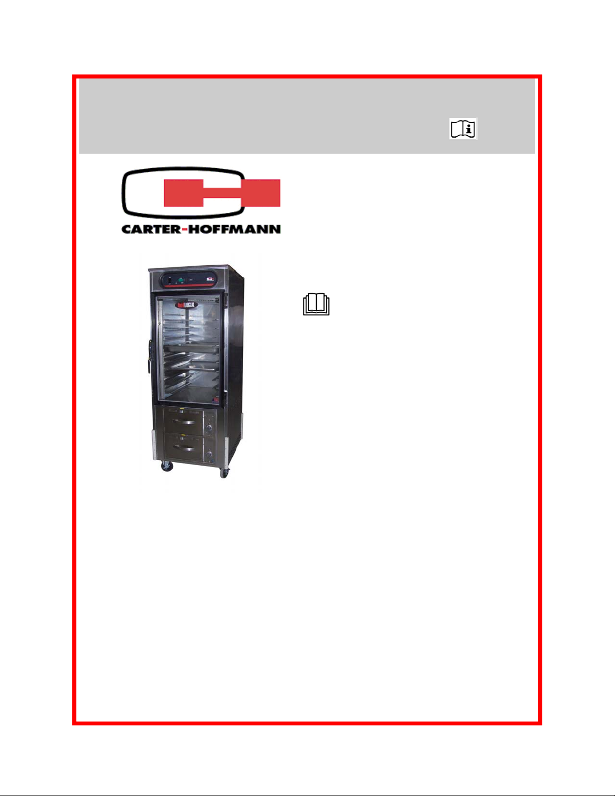
HL8 Series DUAL HOLDING CABINET
with PAN SLIDES & TWO-DRAWER WARMER
MODEL: HL8-10-RW (Formerly HBU10S1XE-RW & HBC20S1XE-RW)
OWNERS / OPERATORS MANUAL
MANUFACTURED BY:
CARTER-HOFFMANN
1551 McCormick Avenue
Mundelein, IL 60060 U.S.A.
Phone: 847-362-5500
Fax: 847-367-8981
Toll Free: 800-323-9793
Email: technicalservice@carter-hoffmann.com
READ THIS MANUAL COMPLETELY
BEFORE OPERATING THIS APPLIANCE
IMPORTANT: DO NOT DISCARD THIS MANUAL
This manual is considered to be part of the appliance and is to
be given to the OWNER of MANAGER, or to the person responsible for training operators of this appliance.
THIS MANUAL IS TO BE UNDERSTOOD BY ALL PERSONS
Contact Carter-Hoffmann if you have questions regarding installation, operation or maintenance of this equipment.
USING OR INSTALLING THIS APPLIANCE.
HL8-10-RW
with optional glass door
TABLE OF CONTENTS
SAFETY PRECAUTIONS 2
FEATURES & SPECIFICATIONS 3
UNPACKING, INSPECTION & FREIGHT DAMAGE 4
INSTALLATION & STARTUP 5
CONTROL PANEL LAYOUT 6
NORMAL OPERATION-HOLDING CABINET 7-8
NORMAL OPERATION-DRAWER WARMER 9-11
FOOD HOLDING GUIDE 12
REGULAR CLEANING PROCEDURES 13-14
MAINTENANCE 15-16
WIRING DIAGRAMS 17
PARTS LIST 18
TROUBLESHOOTING GUIDE 19
WARRANTY STATEMENT 20
Part Number: 18400-3153b Printed in The United States of America Rev: KBA120512
Page 2
SAFETY PRECAUTIONS
WARNING: ELECTRIC SHOCK HAZARD
WARNING
All service requiring access to non-insulated components must be performed by
qualified service personnel. Failure to heed this warning may result in severe
electric shock.
CAUTION: ELECTRIC SHOCK HAZARD
Disconnect this appliance from electrical power before performing any
maintenance or service.
CAUTION: BURN HAZARD
Exposed metal surfaces can be hot to the touch and may cause burns.
IMPORTANT SAFETY INSTRUCTIONS
When using electrical appliances basic safety precautions should be adhered to, including the following:
1) Be familiar with the appliance use, limitations and associated restrictions. Operating instructions must
be read and understood by all persons using or installing this appliance.
2) This appliance must be grounded. Connect only to properly grounded outlet.
3) Use this appliance only for its intended purpose as described in the manual.
a. This equipmen t is specifically designed to hold pre-cooked food at temperature.
b.
c. This equipment is not designed for industrial or laboratory use.
4) Cleanliness of this appliance and its accessories is essential to good sanitation.
This equipment is intended for use in commercial establishments only.
5) DO NOT submerge this appliance in water. This appliance is not jet stream approved. DO NOT direct
water jet or steam jet at this appliance, or at any control panel or wiring. DO NOT splash or pour water
on, in or over any controls, control panel or wiring. DO NOT use corrosive chemicals or vapors in this
appliance.
6) DO NOT store this appliance outdoors. DO NOT use this product near water – for example,
near a kitchen sink, in a wet basement, or near a swimming pool, and the like.
7) DO NOT operate this appliance if it has a damaged cord or plug, if it is not working properly, or if it has
been damaged or dropped. Do not immerse cord or plug in water, keep cord away from heated
surfaces, and do not let cord hang over edge of table or counter.
8) DO NOT cover or block any openings on the appliance.
9) Only qualified service personnel should service this appliance.
NOTE: The technical content of this manual, including any wiring diagrams, schematics, parts br eakdown
illustrations and/or adjustment procedures, is intended for use by qualified technical personnel and is
subject to change without notice.
2
Page 3
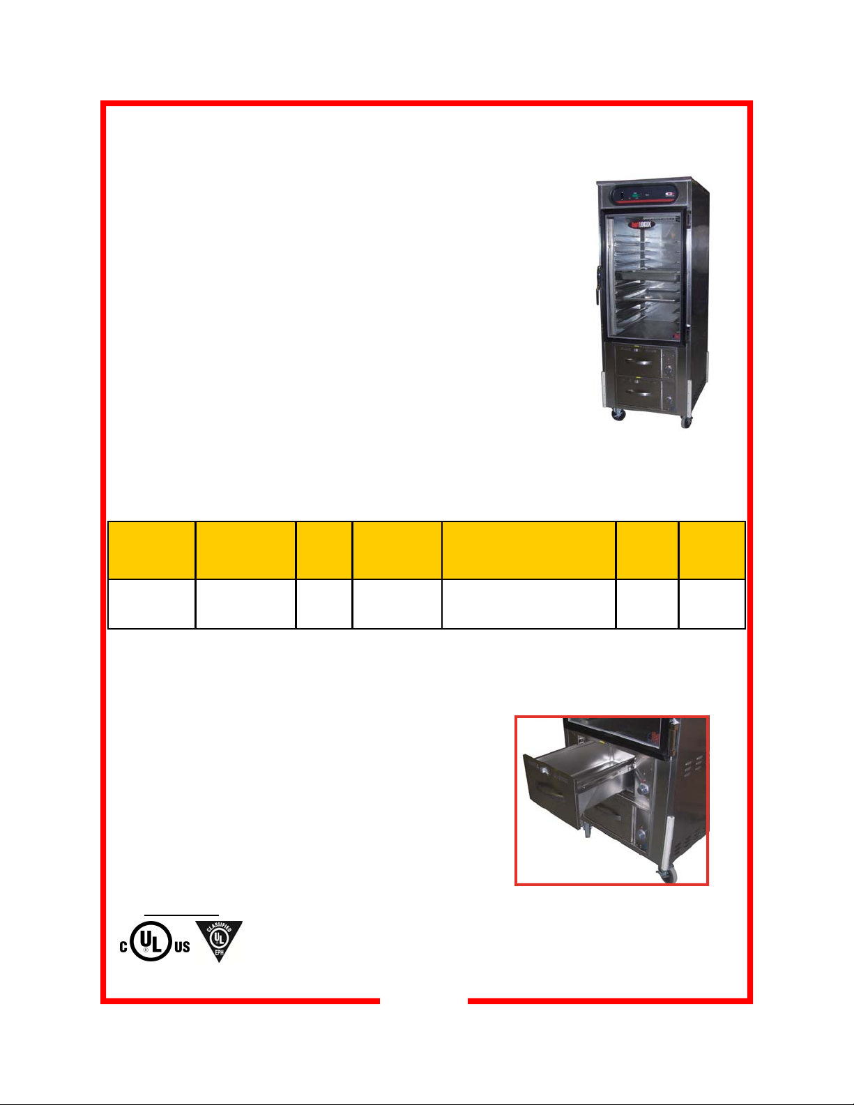
FEATURES & SPECIFICATIONS
hotLOGIX™
Features & Benefits
Get a holding cabinet and a two-drawer warmer - all in one cabinet and
save space!
All stainless steel construction with double pane glass door
Top holding cabinet has precision-engineered top mount heating system
with digital controls and temperature read-out; blower heat for active, even,
fast heat-up and recovery
Adjustable universal pan slides for 18”x26” and 12”x20” pans; optional
fixed angle slides for 18”x26” pans
Two drawer warmer built into bottom of unit; accommodates 12”x20” steam
table pans up to 6” deep, end-loaded (Wells Mfg Model # RWN-26)
Individual thermostatic temperature control for each drawer with adjustable
front vents to allow humidity control
Self-latching, one-touch drawer closure
Heavy-duty casters, two swivel, two swivel with brake
Dual Warming Cabinet with Pan Slides and Two-Drawer Warmer
Model
Number
HBU10S1XE-RW
* Standard spacing at 3”, adjustable on 1-1/2” centers.
Cabinet Pan/Tray
Capacity*
12”x20” 18”x26”
20 10 10 2
Slide
Pairs
Provided
Drawer Warmer
Pan Capacity
12”x 20”
(up to 6” deep)
(one per draw-
er)
Overall Dimensions
Height Depth Width
in (mm)
76-3/8 32-5/8 28-1/4
(1940) (829) (718)
HL8-10-RW
shown with optional double-pane
tempered glass door
Caster
Diameter
in (mm)
5
(127)
Class 100
Shipping
Weight
lbs (kgs)
458
(208)
Electrical Information:
120 volt, 1900 watts, 16A, 1PH, 60Hz, NEMA 5-20P
plug. Ten foot rubber cord with 3 prong grounding plug.
APPROVALS :
NSF/ANSI 4
3
Page 4
UNPACKING AND INSPECTION
This appliance
should be
thoroughly
cleaned prior to use.
See the CLEANING
INSTRUCTIONS in
this manual.
NOTE: DO NOT discard
the carton or other
packing materials until
you have inspected the
appliance for hidden
damage and checked it
for proper operation.
Refer to FREIGHT
DAMAGE CLAIM
PROCEDURE on
bottom of this page.
UNPACKING AND INSPECTION
1. Remove the cabinet from shipping carton, ensuring that all packing materials and protective plastic has been removed from the
unit.
2. Inspect all components for completeness and condition.
3. If any freight damage is present, a freight claim must be filed immediately with the shipping company.
4. Freight damage is not covered under warranty.
5. Check to insure all components are included: cabinet, instruction
packet and additional accessories.
6. Read operation instructions completely.
7. Appliance should be thoroughly cleaned before use. See
CLEANING INSTRUCTIONS (pages 13-14) in this manual.
8. Carefully account for all components and accessories before discarding packing materials. Store all accessories in a convenient
place for later use.
COMPONENTS
Cabinet
10 pair universal pan slides in box (HBU only); HBC pan slides
are welded to the pan racks on each interior side wall
2 Drawer insert pans (drawer warmers)
Humitrol racks (if ordered with unit)
FREIGHT DAMAGE CLAIM PROCEDURE
NOTE: For your protection, please note that equipment in this shipment was carefully inspected
and packaged by skilled personnel before leaving the factory. Upon acceptance of this shipment,
the transportation company assumes full responsibility for its safe delivery.
IF SHIPMENT ARRIVES DAMAGED:
1. VISIBLE LOSS OR DAMAGE: Be certain that any visible loss or damage is noted on the freight
bill or express receipt, and that the note of loss or damage is signed by the delivery person.
2. FILE CLAIM FOR DAMAGE IMMEDIATELY: Regardless of the extent of damage. Contact
your dealer immediately.
3. CONCEALED DAMAGE: If damage is unnoticed until the merchandise is unpacked, notify the
transportation company or carrier immediately, and then file a “CONCEALED DAMAGE” claim
with them. This should be done within fifteen (15) days from the date the delivery was made to
you. Be sure to retain the container for inspection.
Carter-Hoffmann cannot assume liability for damage or loss incurred in transit, freight damage is
not covered under warranty. We will, however, at your request, supply you with the necessary
documents to support your claim.
4
Page 5
INSTALLATION and START-UP
WARNING:
Risk of personal injury
Installation procedures must be
performed by a qualified technician
with full knowledge of all applicable
electrical codes. Failure could
result in personal injury and property damage.
IMPORTANT:
Power cord is 10' long
If necessary, contact a licensed
electrician to install an appropriate
20 amp electrical circuit with correct
NEMA receptacle.
DO NOT use an extension cord.
CAUTION:
Electrical Shock Hazard
LOCATION
For proper operation and maximum performance, locate the
unit in an ambient air temperature of 70ºF (21ºC).
Avoid placement in areas near exhaust fans or where there
are active air movements.
For safe operation and maximum performance, locate the
unit at least 2” from any wall or combustible material. Avoid
storing flammable or combustible materials in, on or near the
appliance.
Unit must be on a solid level surface.
GROUNDING INSTRUCTIONS
This appliance is equipped with a cord having a grounding
wire with a grounding plug which must be plugged into an
outlet that is properly installed and grounded. In the event of
an electrical short circuit, grounding reduces the risk of electric shock by providing an escape wire for the electric current.
WARNING—Improper use of the grounding can result in
a risk of electric shock. Consult a qualified electrician or
service agent if the grounding instructions are not completely
understood, or if doubt exists as to whether the appliance is
properly grounded.
The ground prong of the power
cord is part of a system designed to
protect you from electric shock in
the event of internal damage.
DO NOT cut off the large round
ground prong or twist a blade to fit
an existing receptacle.
IMPORTANT:
Not under warranty
Damage to unit due to being
connected to the wrong voltage or
phase is NOT covered by warranty.
WARNING:
Risk of personal injury
Unit is not waterproof, to avoid
electrical shock, keep unit and
counter from being submerged in
water. Do not operate if unit has
been in contact with water.
To prevent an electrical shock hazard between the
appliance and other appliances or metal parts in close
vicinity, an equalization-bonding stud is provided. An
equalization bonding lead must be connected to this
stud and the other appliances/metal parts to provide
sufficient protection against potential difference. The
terminal is marked with the following symbol:
START-UP
1. Prior to use, thoroughly clean the interior of the unit,
per the instructions in this manual.
2. Plug the power cord of the cabinet into a grounded outlet with a electrical service according to the electrical
information provided at right.
3. Set POWER switch to the “ON” position.
4. Do not load product into the cabinet. Allow the heat to
remove any residual oils which may adhere to inside
metal surfaces. A slight emission of smoke is common
during the first few hours of operation.
Electrical Information: operates on 120 volts, 60 cycle,
2000 watts, 16.7 amps. NEMA 5-20P plug. Ten foot rubber
cord with 3-prong grounding plug
5
Page 6
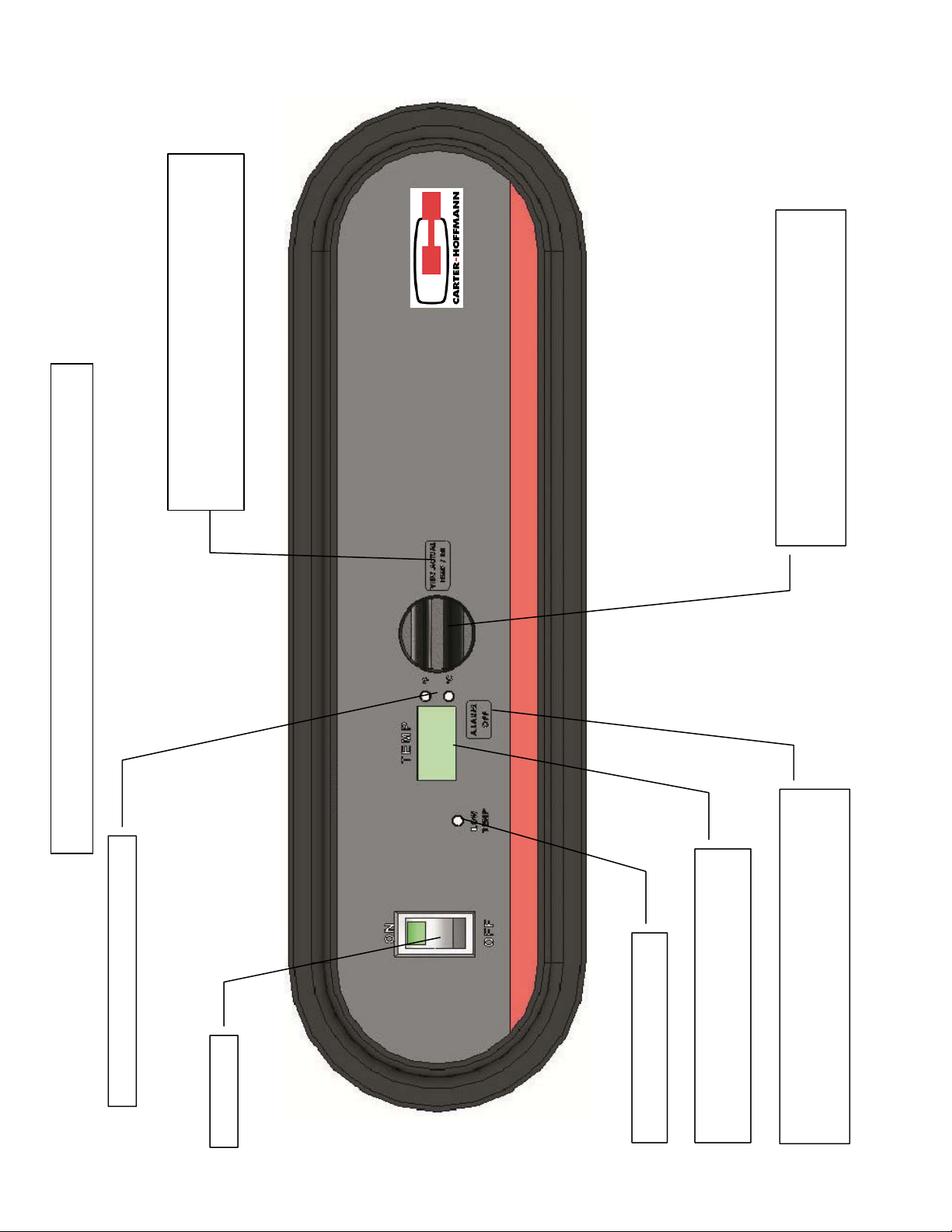
Press to show actual Temperature inside cabinet.
Press and hold for 10 seconds to toggle the tempera-
Holding Cabinet Control panel layout
ture scale between Fahrenheit to Celsius
Turn knob clockwise to increase temperature set-
point; turn counterclockwise to reduce tempera-
ture setpoint
6
hotLOGIX
Temperature scale indicator (°F or °C)
Power Switch
Low Temperature indicator
Displays set-point and actual cabinet tem-
perature values
Press to silence low temperature alarm. Press and
hold for 10 seconds to enter Alarm Toggle menu
Page 7

HOLDING CABINET—NORMAL OPERATION
CAUTION:
HOT SURFACE
Inner surfaces of the unit
will be very hot during and
after operation.
Avoid touching the cabinet
when loading or removing
product.
Factory default setpoints:
- temperature: 160ºF
- low temp alarm: 140ºF
Operating ranges:
- temp alarm: 80ºF-180ºF
- air temp: 90ºF-200ºF
The factory default for the
temperature display is in ºF.
To change the display to
read in ºC, push in and hold
the view actual button for 10
seconds. The display will
now read in ºC.
To change the display temp
back to ºF, repeat the same
procedure above.
FIRST USE
Turn the cabinet on using the power switch located on the far left
side of the control panel. Once the switch is turned on, the control
display will illuminate.
When the cabinet is first turned on, the temperature display will show
the current hardware / software revision, for example: “r26”. Then
display will then alternately flash “PrE” and the set point values.
To adjust the temperature setting, rotate the TEMP dial to the desired set point and stop. After 3 seconds, if setting is adjusted, the
newly adjusted value will be stored in the controller’s memory. If the
cabinet power is interrupted, the last value set will be the new value
restored upon power being restored.
It will take approximately 30 minutes for the cabinet to warm up to a
factory default setting of 160º F. Once the set point is reached, a
short alarm burst will be heard to indicate that the cabinet has
reached the set point.
NOTE: The holding cabinet section of this appliance
and drawer warmers can be operated independently of
one another. See pages 9-11 for operation instructions
for the drawer warmers.
hotLOGIX
7
Page 8

HOLDING CABINET—NORMAL OPERATION (CONT)
CAUTION:
HOT SURFACE
Inner surfaces of the unit
will be very hot during and
after operation.
Avoid touching the cabinet
when loading or removing
product.
Factory default setpoints:
- temperature: 160ºF
- low temp alarm: 140ºF
Operating ranges:
- temp alarm: 80ºF-180ºF
- air temp: 90ºF-200ºF
LOW TEMPERATURE ALARM
The cabinet is equipped with a low temperature alarm feature. When
the alarm is active, the temperature display will indicate “LO” and then
“TEMP” and the audible alarm will sound. To silence the alarm,
press the “alarm off” button. If the actual temperature is still below the
low temperature alarm set point after 5 minutes, the alarm will sound
again.
This alarm can be triggered by the door being left open, loading of
product that is much colder than the temperature set point in the cabinet or due to a malfunction of the heating system.
To change the low temperature alarm set point, press and hold the
“alarm off” button while adjusting the temperature set point knob to
the new desired value. Due to food safety concerns, the low tem-
perature alarm should not be set below 140 degrees F. After 3
seconds, the controller will accept the new set point. The new value
will be stored in the controller memory until the next time the value is
changed.
The audible alarm for low cabinet temperature can be turned off.
The factory default is ON. To enter into the adjustment mode, push
in and hold the “alarm off” button until the alarm sounds. The display
will read either (ON or OFF). To change the status, push the temperature knob, which will function as a toggle switch to select between
ON or OFF. After 10 seconds, the controller will accept the desired
audible alarm function (either ON or OFF). If OFF is selected, the
temperature display will still indicate “LO” and “TEMP” if the low temp
alarm is tripped.
8
Page 9

OPTIONAL
DRAWER WARMER—FEATURES & CONTROLS
9
Page 10

DRAWER WARMER—NORMAL OPERATION
CAUTION:
HOT SURFACE
Exposed surfaces can be
hot to the touch and may
cause burns
Avoid touching the cabinet
when loading or removing
product.
HEATING OPTIONS
MOIST HEAT: Moist operation prevents food from drying out as
heat is applied to the warming chamber.
DRY HEAT: For some applications, you may want to store previ-
ously prepared foods in a dry-heat environment.
1. MOIST HEAT WITH PANS
A. The drawer warmers are designed to accommodate any
combination of standard-size, steam table pans.
B. Place a small amount of water in the drawer pan. Place
the steam table pans in the drawer pan.
C. Check the water level periodically, and add water when
necessary
D. Set the front air vent between fully clos ed and half open.
Actual setting will depend on the type and amount of product
stored in the drawer, the temperature setting, and the
frequency in which the drawer is opened.
2. DRY HEAT
A. To warm with dry heat, place the food directly into the empty
(i.e. no water) drawer pan.
3. MOIST HEAT WITH OPTIONAL HUMITROL RACK
A. To set for MOIST OPERATION, remove the Humitrol Rack
from the bottom of the drawer insert pan and carefully pour
approximately 2 quarts of water (1/2” depth) into the pan.
Reinstall rack.
B. When the drawer is closed, the Humitrol Rack allows water
vapor to rise through the stored product in the drawer. The
Humitrol Rack also decreases the sloshing effect of the water
in the pan when the drawer is opened.
C. Place the food directly on the rack. The rack is designed to
support the food off of the steam vents, where condensation
may form.
D. Check the water level in the pan periodically and add water
when necessary.
E. Set the front air vent between fully closed and half open.
Actual setting will depend on the type and amount of product
stored in the drawer, the temperature setting, and the
frequency in which the drawer is opened.
10
Page 11

DRAWER WARMER—NORMAL OPERATION
CAUTION:
HOT SURFACE
Exposed surfaces can be
hot to the touch and may
cause burns
Avoid touching the cabinet
when loading or removing
product.
CAUTION:
ELECTRICAL
SHOCK HAZARD
DO NOT splash or pour
water onto control panel or
wiring.
OPERATION
1. Determine the type of food to be warmed.
2. Refer to the chart below to determine the type of heat required.
3. Set the air vent control for the type of heat, and rotate the thermostat knob to the desired temperature setting.
4. Allow warmer to pre-heat for approximately 30 minutes before
use.
DO’s and DON’TS
DO Always use a drawer pan
DO NOT Place food directly into the warmer cavity
DO Check water level frequently in moist-operation
warmer use
DO Use a Humitrol Rack or insets to hold food for moist
operation
DO Use warm water when adding water to the pan
during moist operation
DO NOT Put ice into a warmer pan. Ice in the pan will cause
condensation on the inside of the warmer cavity
NOTE: The chart below is intended as a guide only. Your own experience with this appliance, type
of foods and method of operation will enable you to determine the temperature controls and air vent
settings best suited to your operation.
OPERATING CHART FOR DRAWER WARMERS
PRODUCT
TYPE
Hard Rolls 160° - 185°F Dry 7-8 Full Open
Soft Rolls 150° - 175°F Moist 6-7 Open - 1/2
Vegetables 175° - 185°F Moist 7-8 Open - 1/2
Meats 165° - 185°F Dry 6-8 Full Open
Fish 165° - 185°F Moist 6-8 Closed
Casseroles 150° - 175°F Dry 6-8 Full Open
Pies, Desserts 160° - 185°F Dry 6-7 Full Open
Taco Shells 150° - 170°F Dry (do not put water in pan) 4-6 Full Open
Corn Chips 150° - 170°F Dry (do not put water in pan) 4-6 Full Open
RECOMMENDED
STORAGE TEMP.
TYPE OF HEAT CONTROL
SETTING
11
AIR VENT
SETTING
Page 12

FOOD HOLDING GUIDE
CAUTION: SAFE
FOOD HOLDING
PRACTICES
RECOMMENDED
Cooking food to a safe temperature, holding at a temperature of at least 140°F
(60°C) is critical in the prevention of foodborne illness.
Hold only cooked, hot food
at 140°F or higher. This
cabinet is not intended to
cook or reheat food. Food
must be at appropriate temperature before being
placed into cabinet.
COOK TO AT LEAST
165°F Destruction of
165°F
140°F
41°F
NOTE: Times and temperatures
observed in a test kitchen environment. Times and temperatures
may vary, depending on initial food
quality, initial cooked temperature
and user expectations of acceptable food quality.
most bacteria
HOLD at 140°F or higher
DANGER ZONE: 41°F
to 140°F Bacteria
grow rapidly
PRODUCT
(Covered Food, except where noted)
Bacon, Canadian 180°F / 82°C 30
Bacon, Crisp (uncovered) 180°F / 82°C 30
Baked Potato 180°F / 82°C 60
Biscuits 170°F / 77°C 60
Casseroles 175°F / 79°C 90
Chops, Sliced Meats 160°F / 71°C 60
Chicken, Fried (uncovered) 170°F / 77°C 30
Chicken, Boneless Breasts 175°F / 79°C 60
Chicken Nuggets, Deep Fried (uncovered) 190°F / 88°C 25
Chicken, Pre-Cooked Grilled Boneless Patties 175°F / 79°C 90
Coffee Cakes (uncovered) 170°F / 77°C 60
Cookies (uncovered) 175°F / 79°C 90
Crab Legs 160°F / 71°C 45
Croissants 170°F / 77°C 45
Eggs 160°F / 71°C 45
Fish, Deep-Fried (uncovered) 170°F / 77°C 30
Fish, Baked 155°F / 68°C 45
Fish, Broiled 155°F / 68°C 45
French Toast 165°F / 74°C 60
Gravies / Sauces 170°F / 77°C 45
Hamburgers / Ground Meat Patties 180°F / 82°C 45
Hot Dogs 180°F / 82°C 90
Muffins 170°F / 77°C 60
Omelets 160°F / 71°C 30
Pancakes 180°F / 82°C 30
Pasta 175°F / 79°C 60
Pastries 165°F / 74°C 30
Pizza (uncovered) 180°F / 82°C 15
Pizza (boxed) 180°F / 82°C 60
Poppers, Deep Fried (uncovered) 190°F / 88°C 25
Poultry, Whole, bone-in 175°F / 79°C 60
Poultry, Cut-up, bone-in 175°F / 79°C 60
Ribs 175°F / 79°C 90
Rice 175°F / 79°C 30
Roasts / Bone-in Meats 165°F / 74°C 90
Sausage 180°F / 82°C 90
Shrimp / Shellfish 150°F / 66°C 60
Soups (broth) 185°F / 85°C 90
Tortillas (soft) 180°F / 82°C 60
Vegetables 175°F / 79°C 45
SET TEMPERATURE
(°F /°C)
MAXIMUM
TIME
(MINUTES)
12
Page 13

DAILY CLEANING PROCEDURES-HOLDING CABINET
CAUTION:
ELECTRIC SHOCK
HAZARD
Disconnect appliance from
electric power before cleaning.
CAUTION:
HOT SURFACE
Exposed surfaces can
be hot to the touch
and may cause burns. Allow
appliance to cool before cleaning.
IMPORTANT:
DO NOT spill or pour
water into controls,
control panel or wiring.
CAUTION:
Beware of sharp edges with sheet metal
during cleaning process.
1. After all food products have been removed from the cabinet,
turn the power switch to “OFF” and allow the cabinet to cool.
2. Unplug the unit prior to any cleaning.
3. Remove the side heat duct and rack assemblies. Clean the
inside of the unit as well as the removed parts. Reinstall when
all parts are dry and clean.
4. Inspect and clean the areas where there are vents or filters,
making sure no water gets into the internal controls or
electrical areas of the cabinet.
5. Plastic control panel should be washed with a clean damp
cloth and chlorine-free detergent. Rinse thoroughly with clean
damp cloth and allow to dry. Do not use abrasive cleaners,
waxes, car polish, or substances containing strong aromatic
solvents or alcohol.
CAUTION:
Cleansers, detergents, degreasers, sanitizers, or bleaching
agents that contain chlorides or phosphates will cause permanent damage to stainless steel products. The damage appears as
pits, eruptions, voids, small holes, severe discoloration or dulling of
the metal finish.
Water with high chloride content can also damage stainless steel.
If unsure of your water quality, we recommend you have it tested.
THIS DAMAGE IS PERMANENT, COSTLY TO REPAIR, AND IS
NOT COVERED BY THE WARRANTY.
RECOMMENDED TIPS FOR CLEANING STAINLESS STEEL
Purpose Frequency Cleaning Agent Method of Application
Routine Daily Soap, ammonia Sponge with cloth, rinse with clear water cleaning
detergent and water and wipe dry.
Smears/ As Stainless steel cleaner Rub with soft cloth as directed on package.
Fingerprints needed or similar products Rub in direction of grain of stainless steel.
Do not use on vinyl trim.
Stubborn Daily Any chloride-free Apply with damp sponge or cloth. Rub in
spots and as or direction of grain of stainless steel. Rinse
stains needed phosphate-free thoroughly, especially if cleaner contains
cleaner chlorine bleach, do not use on vinyl trim.
Hard water Daily Vinegar Swab with cloth.
spots as needed Rinse with water and wipe dry.
13
Page 14

DAILY CLEANING PROCEDURES—DRAWER WARMER
CAUTION:
ELECTRIC SHOCK
HAZARD
Disconnect appliance from
electric power before cleaning.
CAUTION:
HOT SURFACE
Exposed surfaces can
be hot to the touch and may
cause burns. Allow appliance
to cool before cleaning.
IMPORTANT:
DO NOT spill or pour
water into controls,
control panel or wiring.
Water damage is not covered
by warranty.
CAUTION:
Beware of sharp edges with sheet metal
during cleaning process.
PRECAUTIONS: Turn control knob to OFF.
Allow drawers to cool before proceeding.
Remove drawer pans.
FREQUENCY: Minimum—Daily
TOOLS: Warm water and mild detergent
Clean cloth or sponge
1. Remove drawers from warmer:
A. Pull warmer drawer out until fully extended
B. Slide finger along left and right slide rail until you reach the
latches (located at the front end of the cabinet-mounted
rails). Press down on both left and right latch.
C. Pull drawer away from warmer.
2. Clean drawers, drawer pans, Humitrol racks and/or insets with
warm water and mild detergent.
Rinse all components thoroughly with clear water.
Dry all components prior to reinstalling them in warmer.
3. Sweep crumbs and other debris from warmer cavity.
4. Clean the outside of the unit by wiping with a clean cloth or
sponge, warm water and mild detergent. Dry with a clean
cloth, then wipe with a polish formulated for stainless steel.
5. It is important to keep the slide rails clear and free of debris.
Periodic cleaning of the slide rails and other adjoining parts is
necessary to assure smooth drawer operation.
6. Check drawer rollers. Be sure they roll freely and that the slide
rails are free from debris.
7. Be sure cabinet-mounted drawer catch roller is “up”, then
reinstall drawers.
14
Page 15

CABINET MAINTENANCE
WARNING:
DO NOT perform
these procedures
while the cabinet is turned on
or heated. Turn off the power
and wait for the cabinet to cool
to room temperature.
CAUTION:
Do not move cabinet
unless door is securely closed. Serious damage to
hinges and door may result if
bumped into tables, walls, or
other equipment when the
doors are open.
CASTERS
Caster bearings may be equipped with Zerk grease fittings so that
they may be easily lubricated with a grease gun. Lubricate bearings at least once every six months.
REPLACING THE DOOR GASKET
1. Remove the screws located under the gasket on the cabinet.
2. Remove the gasket and discard.
3. Install the new gasket and replace the screws.
REVERSING THE DOOR
Reversing the door takes about 30 minutes & requires two people.
1. Using a small screwdriver, pry off the hinge covers and set
aside. Removing the covers will allow access to the inside
hinge screws. Remove the three screws that hold each hinge
to the cabinet. DO NOT REMOVE THE SCREWS THAT
HOLD THE HINGES TO THE DOOR. Remove the door, taking care not to let it fall.
2. Remove the door strike plate and screws adjacent to the door
opening on the cabinet. Reinstall door strike plate and screws
on opposite side of the cabinet.
3. Screw hinges onto opposite side of the door.
4. With the help of another person, hold door up to the cabinet
and attach with the screws removed in step one. Before tightening the screws, be sure the door is flush, level and square.
Replace the hinge covers.
15
Page 16

DRAWER WARMER MAINTENANCE
WARNING:
DO NOT perform
these procedures
while the cabinet is turned on
or heated. Turn off the power
and wait for the cabinet to cool
to room temperature.
ELECTRIC SHOCK HAZARD
Disconnect appliance from
electric power before cleaning.
CAUTION:
HOT SURFACE
Exposed surfaces can be hot
to the touch and may cause
burns. Allow appliance to cool
before cleaning.
ADJUSTMENTS AND LUBRICATION
PRECAUTIONS: Turn control knob to OFF.
Allow drawers to cool before proceeding.
Remove drawer pans.
FREQUENCY: Minimum—monthly.
Every 2 weeks recommended
TOOLS: Screwdrivers, Phillips (+) and flat blade (-)
Nut drivers, 3/8” and 7/16”
Food-grade lubricant
1. Check slides on cabinet and drawers for cleanliness.
2. Check all rollers on cabinet and drawers for cleanliness and
tightness. Lubricate.
3. Check cabinet drawer stops for operation. Non-spring stops
must rotate freely. Spring-type stops must snap down postitively. Clean and adjust as required.
4. Check cabinet heating element fasteners for tightness.
5. Check all cabinet drawer catches for tightness and operation.
Lubricate. Be certain roller is “out” before attempting to install
drawer.
6. Check cabinet thermobulbs for condition. Thermobulbs must be
securely mounted in the appropriate holder. Arrange repairs for
damaged thermobulbs.
7. Check drawer faceplate and handle fasteners for tightness.
8. Check drawer catch clip for tightness.
9. For drawers equipped with gaskets, examine condition of gasket. Arrange repairs for torn or damaged gaskets.
10. Reinstall drawers and check for proper operation.
16
Page 17

Cabinet
WIRING DIAGRAM
HL8 SERIES WITH DIGITAL CONTROL & DRAWER WARMER
120 VOLT, 1900 WATT, 16 AMP, 1 PH
Note: Drawer warmer and cabinet joined
in box and wired to main power of the
cabinet, creating independent circuit/
power supply.
120v, 1000w
18612-0315
Drawer Warmer
17
Page 18

PARTS LIST—DRAWER WARMER
Part Number Description Part Number Description
18612-0146 120v/450w Drawer Warmer Element 18601-1151 Pilot Light—Drawer Warmer
18600-0024 Thermostat—Drawer Warmer 18608-0032 Knob-Drawer Warmer
PARTS LIST—HOLDING CABINET
Part Number Description Part Number Description
17040-2214 Door gasket 18612-0315 120v, 1000w element (air)
18614-0291 Motor 18602-0160 Rocker switch
18616-0023 Controller 18603-5018 Motor fan blade
18616-0224 24v output transformer 16006-0534 Glass door assembly
29038-4128 Glass door only 18302-0050 Door latch
18304-0030 Door hinges 18614-0314 Cooling Fan
18600-0046 High Limit 18608-0028 Controller Knob
18312-0352 Face Overlay 29037-9042 Black bezel housing
18605-5020 12/3 SO power cord 18606-0221 NEMA 5-20P angled plug
This list is not a complete list of spare parts. Contact Carter-Hoffmann technical service at
800-323-9793 if you do not see the part number you are looking for.
NOTE:
The technical content of this manual, includ-
ing any wiring diagrams, schematics, parts
breakdown illustrations and / or adjustment
procedures, is intended for use ONLY by
qualified technical personnel.
NOTE:
For warranty service, call Carter-Hoffmann direct at 800-323-9793 for authorization, we will
dispatch the nearest authorized service agency.
18
Page 19

TROUBLESHOOTING GUIDE
SYMPTOM POSSIBLE CAUSE SUGGESTED REMEDY
No power on display Not plugged in or ci rcuit breaker
tripped
Power cord damaged Check - replace if required
Power switch damaged or defective Check - replace if required
Food dries out too
quickly in cabinet
Unit is on, cabinet
motors are running
but no heat
Cabinet takes too
long to get to temperature
Cabinet is hot
but low or no airflow
Operation where product temp is too
high or food should be covered
Control incorrectly set or defective Check proper operation or calibration
Internal wiring error
Element hi-limit trip / defective Call service technician
Improper voltage Call service technician to verify
Internal wiring error Call service technician
Circulation motor has quit Call service technician
Improper voltage Call service technician to verify
Check or reset circuit breaker
Connect to proper receptacle
Check product temps going into
holding cabinet; cover food pans
of control
Call service technician
incoming voltage matches cabinet
specifications.
incoming voltage matches cabinet
specifications.
No lights or heat on
drawers
No heat (one drawer)
Food dries out in
drawer warmer
Food gets soggy in
drawer warmer
Drawer falls open Catch roller not extended before clos-
Drawer falls out
when opened
Internal damage Call service technician
Temperature control not set Set for desired temperature
Internal damage Call service technician
Humidity control (air vent) not set OPEN air vent for dry operation.
Water in pan evaporated or low Add water to pan
Food contacting water Use a Humitrol rack
Water level too high Water should be no more than 1/2”
Humidity control (air vent) not set OPEN air vent for dry operation.
ing drawer
Drawer catch damaged Call service technician
Drawer stop dirty Clean and lubricate drawer stop
Drawer stop damaged Call service technician
CLOSE air vent for moist operation.
deep
CLOSE air vent for moist operation.
Be sure catch roller is extended be-
fore installing drawer
19
Page 20

3-YEAR WARRANTY on HOTLOGIX HOLDING CABINETS
Carter-Hoffmann Warranty:
Carter-Hoffmann (“CARTER-HOFFMANN”) warrants to the initial purchaser of its standard Carter
Line Products that CARTER-HOFFMANN will, at its option, repair or replace, during the warranty
period set forth below, any part of such products made necessary due to a defect in material or workmanship which is present when the product leaves its factory and which manifests itself d ur ing th e warranty period under normal use and service.
This warranty applies only to original equipment owned and possessed by the initial purchaser and the
warranty period begins on the date of original shipment from the CARTER-HOFFMANN factory and
extends as follows: to component parts and labor for 12 months (36 months on hotLOGIX, LOGIX3
through LOGIX10 holding cabinets and cook & hold cabinets); to refrigeration compressor unit for
one year (limited to replacement only - not to include labor for removal, repair or replacement).
Repair or replacements under this warranty will be performed, unless otherwise authorized in writing
by CARTER-HOFFMANN, at its factory. All parts or components to be repaired or replaced under this
warranty are to be shipped prepaid to CARTER-HOFFMANN, with reimbursement credit for such part
or component to be given if found by CARTER-HOFFMANN to be defective.
CARTER-HOFFMANN neither makes nor assumes and does not authorize any other person to make or
assume any obligation or liability in connection with its pro ducts other than that covered in this warranty. This warranty applies only within the continental United States and Canada. In Alaska and Hawaii, this warranty applies only to and is limited to the supply of replacement parts.
Warranty Exclusions and Limitations:
Any implied warranty of merchantability or fitness for a particular purpose is hereby specifically dis-
claimed by CARTER-HOFFMANN. There are no warranties, expressed or implied, which extend be-
yond the description on the face hereof. This warranty does not cover and CARTER-HOFFMANN shall
not under any circumstances be liable for any incidental, consequential or other damages (such as in-
jury to persons or property, loss of time, inconvenience, loss of business or profits, or other matters not
specifically covered) arising in connection with the use of, inability to use, or failure of these products.
Specifications subject to change through product improvement and innovation.
Carter-Hoffmann
1551 McCormick Ave.
Mundelein, Illinois, 60060 USA
Phone: 847-362-5500 Toll free: 800-323-9793 Fax: 847-367-8981
Sales and Marketing E-mail: sales@carter-hoffmann.com
Service E-mail: technicalservice@carter-hoffmann.com
Company Website: www.carter-hoffmann.com
20
 Loading...