

Page 1
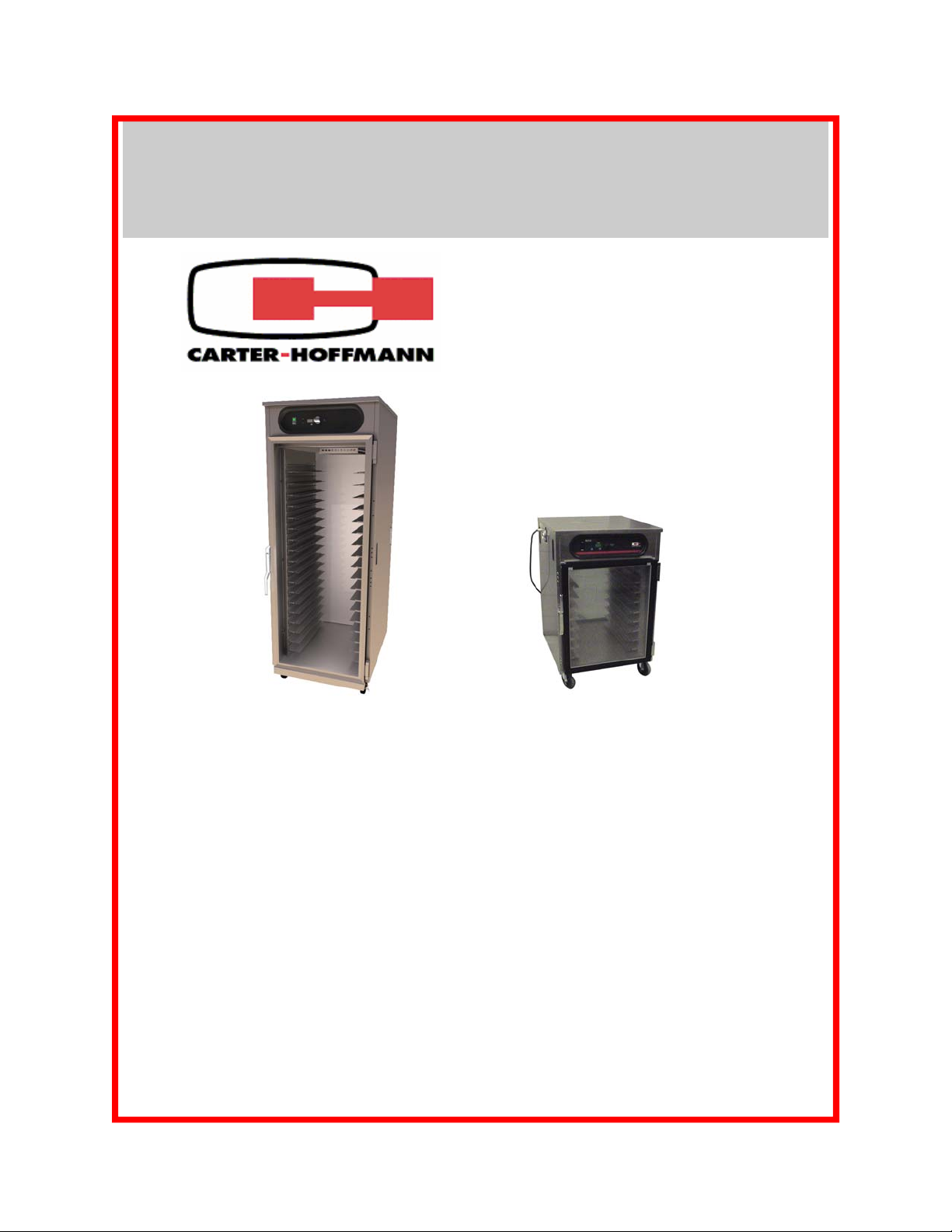
LOGIX
8 Series
HOLDING CABINETS
MODELS: HBU18S1XE, HBU14S1XE, HBU8S1XE & HBU5S1XE
HBC36S1XE, HBC28S1XE, HBC16S1XE & HBC10S1XE
OWNERS / OPERATORS MANUAL
MANUFACTURED BY:
CARTER-HOFFMANN
1551 McCormick Avenue
Mundelein, IL 60060 U.S.A.
Phone: 847-362-5500
Fax: 847-367-8981
Toll Free: 800-323-9793
Email: Service@Carter-Hoffmann.com
HBU18S1GE
with optional glass door
TABLE OF CONTENTS
HBU8S1GE-P
with optional pass-
through glass doors
SAFETY PRECAUTIONS 2
FEATURES & SPECIFICATIONS 3
UNPACKING, INSPECTION & FREIGHT DAMAGE 4
INSTALLATION & STARTUP 5
CONTROL PANEL LAYOUT 6
NORMAL OPERATION 7-8
FOOD HOLDING GUIDE 9
REGULAR CLEANING PROCEDURES 10
CABINET MAINTENANCE 11
WIRING DIAGRAM 12
TROUBLESHOOTING GUIDE 13
WARRANTY STATEMENT 14
Part Number: 18400-3119c Printed in The United States of America Rev: KBA100710
Page 2
SAFETY PRECAUTIONS
WARNING: ELECTRIC SHOCK HAZARD
WARNING
All service requiring access to non-insulated components must be performed by
qualified service personnel. Failure to heed this warning may result in severe
electric shock.
CAUTION: ELECTRIC SHOCK HAZARD
Disconnect this appliance from electrical power before performing any
maintenance or service.
CAUTION: BURN HAZARD
Exposed metal surfaces can be hot to the touch and may cause burns.
IMPORTANT SAFETY INSTRUCTIONS
When using electrical appliances basic safety precautions should be adhered to, incl uding the following:
1) Be familiar with the appliance use, limitations and associated restrictions. Operating instructions must
be read and understood by all persons using or installing this appliance.
2) This appliance must be grounded. Connect only to properly grounded outle t.
3) Use this appliance only for its intended purpose as described in the manual.
a. This equipment is specifically designed to hold pre-cooked food at temperature.
b.
c. This equipment is not designed for industrial or laboratory use.
4) Cleanliness of this appliance and its accessories is essential to good sanitation.
This equipment is intended for use in commercial establishments only.
5) DO NOT submerge this appliance in water. This appliance is not jet stream approved. DO NOT direct
water jet or steam jet at this appliance, or at any control panel or wiring. DO NOT splash or pour
water on, in or over any controls, control panel or wiring. DO NOT use corrosive chemicals or vapors
in this appliance.
6) DO NOT store this appliance outdoors. DO NOT use this product near water – for example,
near a kitchen sink, in a wet basement, or near a swimming pool, and the like.
7) DO NOT operate this appliance if it has a damaged cord or plug, if it is not working properly, or if it has
been damaged or dropped. Do not immerse cord or plug in water, keep cord away from heated
surfaces, and do not let cord hang over edge of table or counter.
8) DO NOT cover or block any openings on the appliance.
9) Only qualified service personnel should service this appliance.
NOTE:
The technical content of this manual, including any wiring diagrams, schem atics, parts breakdown
illustrations and/or adjustment procedures, is intended for use by qualified technical personnel and is
subject to change without notice.
2
Page 3
FEATURES & SPECIFICATIONS
Features & Benefits
• Precision-engineered heat ducts with blower for even heat throughout cabinet.
• Digitally controlled and monitored temperature, with digital temperature read-out
& low temperature safety alarm
• Under-counter, 1/2-size, 3/4 size and full size
• Heavy-duty casters, two swivel with brake, two rigid
• Field reversible stainless steel doors are standard. Clear glass doors are optional.
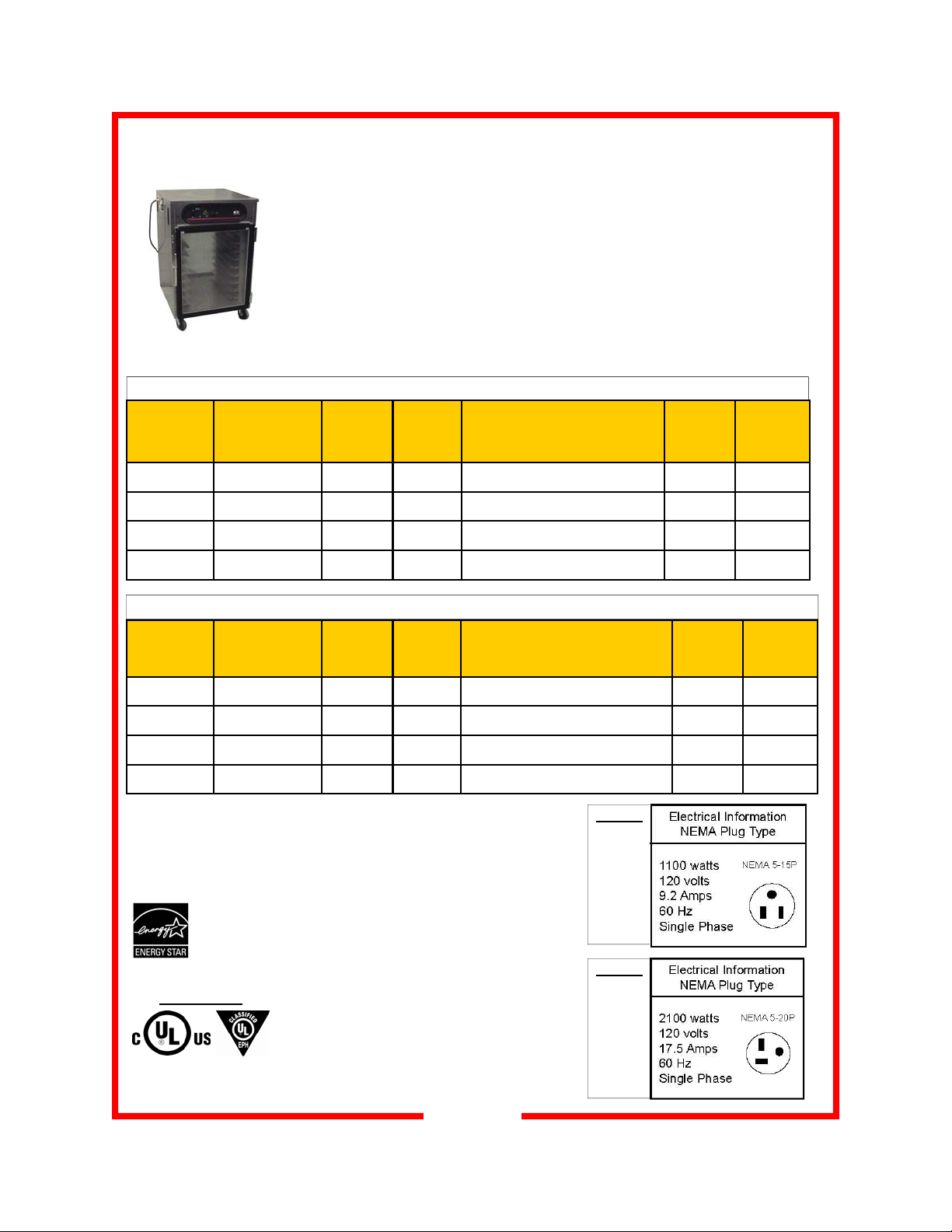
Cabinets with Adjustable Universal Slides for 12”x20” Pans, 18” x 26” Trays and Gastronorm Pans
Model
Number
HBU5S1XE
(under-counter)
HBU8S1XE
(
1/2 size)
HBU14S1XE
(3/4 size)
HBU18S1XE
(full size)
Pan/Tray
Capacity
Adjustable spacing from
1.5” to 3” centers
12”x20” 18”x26”
10 5 5 15-5/16
16 8 8 24-15/16
28 14 14 42-1/2
36 18 18 54-1/2
Slide Pairs
Provided
Inside
Working
Height
in (mm)
(389)
(633)
(1080)
(1384)
Overall Dimensions
Height Depth Width
in (mm)
33-1/2 33-1/16 28 3/16
(851) (840) (716)
45-1/2 33-1/16 28 3/16
(1156) (840) (716)
64-3/8 33-1/16 28 3/16
(1635) (840) (716)
76-3/8 33-1/16 28 3/16
(1940) (840) (716)
Caster
Diameter
in (mm)
3
(76)
5
(127)
5
(127)
5
(127)
Class 100
Shipping
Weight
lbs (kg)
261
(118)
312
(141)
413
(189)
485
(220)
Model
Number
HBC10S1XE
(under-counter)
HBC16S1XE
(1/2 size)
HBC28S1XE
(3/4 size)
HBC36S1XE
(
full size)
APPROVALS :
Pan/Tray
Capacity
18”x26”
Fixed spacing @
1.5” centers
10 10 15-5/16
16 16 24-15/16
28 28 42-1/2
36 36 54-1/2
All models except
HBU5S1XE and
HBC10S1XE
Cabinets with Fixed Channel Slides for 18” x 26” Trays
Slide Pairs
Provided
Inside
Working
Height
in (mm)
(389)
(633)
(1080)
(1384)
Overall Dimensions
Height Depth Width
33-1/2 33-1/16 28 3/16
(851) (840) (716)
45-1/2 33-1/16 28 3/16
(1156) (840) (716)
64-3/8 33-1/16 28 3/16
(1635) (840) (716)
76-3/8 33-1/16 28 3/16
(1940) (840) (716)
in (mm)
MODELS
HBU5
HBU8
HBC10
HBC16
MODELS
HBU14
HBU18
HBC28
HBC36
Caster
Diameter
in (mm)
3
(76)
5
(127)
5
(127)
5
(127)
Class 100
Shipping
Weight
lbs (kg)
251
(114)
302
(137)
403
(188)
475
(215)
NSF/ANSI 4
3
Page 4
UNPACKING AND INSPECTION
This appliance
should be
thoroughly
cleaned prior to use.
See the CLEANING
INSTRUCTIONS in
this manual.
NOTE: DO NOT discard
the carton or other
packing materials until
you have inspected the
appliance for hidden
damage and checked it
for proper operation.
Refer to FREIGHT
DAMAGE CLAIM
PROCEDURE on
bottom of this page.
1. Remove the cabinet from shipping carton, ensuring that all pack-
2. Inspect all components for completeness and condition.
3. If any freight damage is present, a freight claim must be filed im-
4. Freight damage is not covered under warranty.
5. Check to insure all components are included: cabinet, instruction
6. Read operation instructions completely.
7. Appliance should be thoroughly cleaned before use. See
ing materials and protective plastic has been removed from the
unit.
mediately with the shipping company.
packet and additional accessories.
CLEANING INSTRUCTIONS in this manual.
UNPACKING AND INSPECTION
FREIGHT DAMAGE CLAIM PROCEDURE
NOTE: For your protection, please note that equipment in this shipment was carefully inspected
and packaged by skilled personnel before leaving the factory. Upon acceptance of this shipment,
the transportation company assumes full responsibility for its safe delivery.
IF SHIPMENT ARRIVES DAMAGED:
1. VISIBLE LOSS OR DAMAGE: Be certain that any visible loss or damage is noted on the freight
bill or express receipt, and that the note of loss or damage is signed by the delivery person.
2. FILE CLAIM FOR DAMAGE IMMEDIATELY
your dealer immediately.
3. CONCEALED DAMAGE: If damage is unnoticed until the merchandise is unpacked, notify the
transportation company or carrier immediately, and then file a “CONCEALED DAMAGE” claim
with them. This should be done within fifteen (15) days from the date the delivery was made to
you. Be sure to retain the container for inspection.
Carter-Hoffmann cannot assume liability for damage or loss incurred in transit, freight damage is
not covered under warranty. We will, however, at your request, supply you with the necessary
documents to support your claim.
: Regardless of the extent of damage. Contact
4
Page 5
INSTALLATION and START-UP
WARNING:
Risk of personal injury
Installation procedures must be
performed by a qualified technician
with full knowledge of all applicable
electrical codes. Failure could
result in personal injury and property damage.
IMPORTANT:
Power cord is 10' long
If necessary, contact a licensed
electrician to install an appropriate
20 amp electrical circuit with correct
NEMA receptacle.
DO NOT use an extension cord.
CAUTION:
Electrical Shock Hazard
T
he ground prong of the power
cord is part of a system designed to
protect you from electric shock in
the event of internal damage.
DO NOT cut off the large round
ground prong or twist a blade to fit
an existing receptacle.
IMPORTANT:
Not under warranty
Damage to unit due to being
connected to the wrong voltage or
phase is NOT covered by warranty.
WARNING:
Risk of personal injury
Unit is not waterproof, to avoid
electrical shock, keep unit and
counter from being submerged in
water. Do not operate if unit has
been in contact with water.
LOCATION
For proper operation and maximum performance, locate the
unit in an ambient air temperature of 70ºF (21ºC).
Avoid placement in areas near exhaust fans or where there
are active air movements.
For safe operation and maximum performance, locate the
unit at least 2” from any wall or combustible material.
Unit must be on a solid level surface.
GROUNDING INSTRUCTIONS
This appliance is equipped with a cord having a grounding
wire with a grounding plug which must be plugged into an
outlet that is properly installed and grounded. In the event of
an electrical short circuit, grounding reduces the risk of electric shock by providing an escape wire for the electric current.
WARNING—Improper use of the grounding can result in
a risk of electric shock. Consult a qualified electrician or
service agent if the grounding instructions are not completely
understood, or if doubt exists as to whether the appliance is
properly grounded.
START-UP
1. Prior to use, thoroughly clean
the interior of the unit, per the
instructions in this manual.
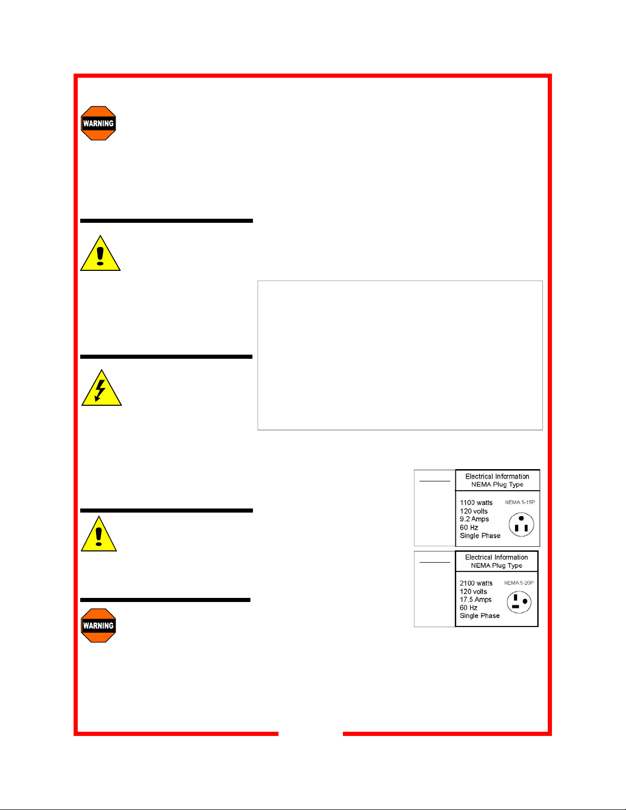
2. Plug the power cord of the
cabinet into a grounded outlet
with a electrical service according to the electrical information provided at right.
3. Set POWER switch to the
“ON” position.
4. Do not load product into the
cabinet. Allow the heat to
remove any residual oils
which may adhere to inside metal surfaces. A slight
emission of smoke is common during the first few hours
of operation.
MODELS
HBU5
HBU8
HBC10
HBC16
MODELS
HBU14
HBU18
HBC28
HBC36
5
Page 6

Press to show actual Temperature inside cabinet.
Control panel layout
Press for 10 seconds to toggle the temperature scale
between Fahrenheit to Celsius
Turn knob clockwise to increase temperature set-
point; turn counterclockwise to reduce tempera-
ture setpoint
6
hotLOGIX
Temperature scale indicator (°F or °C)
Power Switch
Low Temperature indicator
Displays set-point and actual cabinet tem-
perature values
Press to silence low temperature alarm. Press for 10
seconds to enter Alarm Toggle menu
Page 7

NORMAL OPERATION
CAUTION:
HOT SURFACE
Inner surfaces of the unit
will be very hot during and
after operation.
Avoid touching the cabinet
when loading or removing
product.
Factory default setpoints:
- temperature: 160ºF
- low temp alarm: 140ºF
Operating ranges:
- temp alarm: 80ºF-180ºF
- air temp: 90ºF-200ºF
The factory default for the
temperature display is in ºF.
To change the display to
read in ºC, push in and hold
the view actual button for 10
seconds. The display will
now read in ºC.
To change the display temp
back to ºF, repeat the same
procedure above.
FIRST USE
Turn the cabinet on using the power switch located on the far left
side of the control panel. Once the switch is turned on, the control
display will illuminate.
When the cabinet is first turned on, the temperature display will show
the current hardware / software revision, for example: “r26”. Then
display will then alternately flash “PrE” and the set point values.
To adjust the temperature setting, rotate the TEMP dial to the desired set point and stop. After 3 seconds, if setting is adjusted, the
newly adjusted value will be stored in the controller’s memory. If the
cabinet power is interrupted, the last value set will be the new value
restored upon power being restored.
It will take approximately
factory default setting of 160º F. Once the set point is reached, a
short alarm burst will be heard to indicate that the cabinet has
reached the set point.
30 minutes for the cabinet to warm up to a
hotLOGIX
7
Page 8

NORMAL OPERATION (CONT)
CAUTION:
HOT SURFACE
Inner surfaces of the unit
will be very hot during and
after operation.
Avoid touching the cabinet
when loading or removing
product.
Factory default setpoints:
- temperature: 160ºF
- low temp alarm: 140ºF
Operating ranges:
- temp alarm: 80ºF-180ºF
- air temp: 90ºF-200ºF
LOW TEMPERATURE ALARM
The cabinet is equipped with a low temperature alarm feature. When
the alarm is active, the temperature display will indicate “LO” and then
“TEMP” and the audible alarm will sound. To silence the alarm,
press the “alarm off” button. If the actual temperature is still below the
low temperature alarm set point after 5 minutes, the alarm will sound
again.
This alarm can be triggered by the door being left open, loading of
product that is much colder than the temperature set point in the cabinet or due to a malfunction of the heating system.
To change the low temperature alarm set point, press and hold the
“alarm off” button while adjusting the temperature set point knob to
the new desired value. Due to food safety concerns, the low tem-
perature alarm should never be set below 140 degrees F. After 3
seconds, the controller will accept the new set point. The new value
will be stored in the controller memory until the next time the value is
changed.
The audible alarm for low cabinet temperature can be turned off.
The factory default is ON. To enter into the adjustment mode, push
in and hold the “alarm off” button until the alarm sounds. The display
will read either (ON or OFF). To change the status, push the temperature knob, which will function as a toggle switch to select between ON or OFF. After 10 seconds, the controller will accept the
desired audible alarm function (either ON or OFF). If OFF is selected, the temperature display will still indicate “LO” and “TEMP” if
the low temp alarm is tripped.
8
Page 9

FOOD HOLDING GUIDE
CAUTION: SAFE
FOOD HOLDING
PRACTICES
RECOMMENDED
Cooking food to a safe temperature, holding at a temperature of at least 140°F is
critical in the prevention of
foodborne illness. Hold only
cooked, hot food at 140°F
or higher. This cabinet is
not intended to cook or reheat food. Food must be at
appropriate temperature
before being placed into
cabinet.
COOK TO AT LEAST
165°F Destruction of
165°F
140°F
41°F
NOTE: Times and temperatures
observed in a test kitchen environment. Times and temperatures
may vary, depending on initial food
quality, initial cooked temperature
and user expectations of acceptable food quality.
most bacteria
HOLD at 140°F or higher
DANGER ZONE: 41°F
to 140°F Bacteria
grow rapidly
PRODUCT
(Covered Food, except where noted)
Bacon, Canadian 180°F / 82°C 30
Bacon, Crisp (uncovered) 180°F / 82°C 30
Baked Potato 180°F / 82°C 60
Biscuits 170°F / 77°C 60
Casseroles 175°F / 79°C 90
Chops, Sliced Meats 160°F / 71°C 60
Chicken, Fried (uncovered) 170°F / 77°C 30
Chicken, Boneless Breasts 175°F / 79°C 60
Chicken Nuggets, Deep Fried (uncovered) 190°F / 88°C 25
Chicken, Pre-Cooked Grilled Boneless Patties 150°F / 66°C 90
Coffee Cakes (uncovered) 170°F / 77°C 60
Cookies (uncovered) 175°F / 79°C 90
Crab Legs 160°F / 71°C 45
Croissants 170°F / 77°C 45
Eggs 160°F / 71°C 45
Fish, Deep-Fried (uncovered) 170°F / 77°C 30
Fish, Baked 155°F / 68°C 45
Fish, Broiled 155°F / 68°C 45
French Toast 165°F / 74°C 60
Gravies / Sauces 170°F / 77°C 45
Hamburgers / Ground Meat Patties 180°F / 82°C 45
Hot Dogs 180°F / 82°C 90
Muffins 170°F / 77°C 60
Omelets 160°F / 71°C 30
Pancakes 180°F / 82°C 30
Pasta 175°F / 79°C 60
Pastries 165°F / 74°C 30
Pizza (uncovered) 180°F / 82°C 15
Pizza (boxed) 180°F / 82°C 60
Poppers, Deep Fried (uncovered) 190°F / 88°C 25
Poultry, Whole, bone-in 175°F / 79°C 60
Poultry, Cut-up, bone-in 175°F / 79°C 60
Ribs 175°F / 79°C 90
Rice 175°F / 79°C 30
Roasts / Bone-in Meats 165°F / 74°C 90
Sausage 180°F / 82°C 90
Shrimp / Shellfish 150°F / 66°C 60
Soups (broth) 185°F / 85°C 90
Tortillas (soft) 180°F / 82°C 60
Vegetables 175°F / 79°C 45
SET TEMPERATURE
(°F /°C)
MAXIMUM
TIME
(MINUTES)
9
Page 10

DAILY CLEANING PROCEDURES
CAUTION:
ELECTRIC SHOCK
HAZARD
Disconnect appliance from
electric power before cleaning.
CAUTION:
HOT SURFACE
Exposed surfaces can
be hot to the touch and may
cause burns. Allow appliance
to cool before cleaning.
IMPORTANT:
DO NOT spill or pour
water into controls,
control panel or wiring.
Water damage is not covered
by warranty.
CAUTION
Beware of sharp
edges with sheet
metal during cleaning process.
:
1. After all food products have been removed from the cabinet,
turn the power switch to “OFF” and allow the cabinet to cool.
2. Unplug the unit prior to any cleaning.
3. Remove the side heat duct and rack assemblies. Clean the
inside of the unit as well as the removed parts. Reinstall when
all parts are dry and clean.
4. Inspect and clean the areas where there are vents or filters,
making sure no water gets into the internal controls or
electrical areas of the cabinet.
5. Plastic control panel should be washed with a clean damp
cloth and chlorine-free detergent. Rinse thoroughly with clean
damp cloth and allow to dry. Do not use abrasive cleaners,
waxes, car polish, or substances containing strong aromatic
solvents or alcohol.
CAUTION:
Cleansers, detergents, degreasers, sanitizers, or bleaching
agents that contain chlorides or phosphates will cause permanent damage to stainless steel products. The damage appears as
pits, eruptions, voids, small holes, severe discoloration or dulling of
the metal finish.
Water with high chloride content can also damage stainless steel.
If unsure of your water quality, we recommend you have it tested.
THIS DAMAGE IS PERMANENT, COSTLY TO REPAIR, AND IS
NOT COVERED BY THE WARRANTY.
RECOMMENDED TIPS FOR CLEANING STAINLESS STEEL
Purpose Frequency Cleaning Agent Method of Application
Routine Daily Soap, ammonia Sponge with cloth, rinse with clear water
cleaning detergent and water and wipe dry.
Smears/ As Stainless steel cleaner Rub with soft cloth as directed on package.
Fingerprints needed or similar products Rub in direction of grain of stainless steel.
Do not use on vinyl trim.
Stubborn Daily Any chloride-free Apply with damp sponge or cloth. Rub in
spots and as or direction of grain of stainless steel. Rinse
stains needed phosphate-free thoroughly, especially if cleaner contains
cleaner chlorine bleach, do not use on vinyl trim.
Hard water Daily Vinegar Swab with cloth.
spots as needed Rinse with water and wipe dry.
10
Page 11

CABINET MAINTENANCE
WARNING:
DO NOT perform
these procedures
while the cabinet is turned on
or heated. Turn off the power
and wait for the cabinet to cool
to room temperature.
CAUTION:
Do not move cabinet
unless door is securely closed. Serious damage to hinges and door may
result if bumped into tables,
walls, or other equipment when
the doors are open.
CASTERS
Caster bearings may be equipped with Zerk grease fittings so that
they may be easily lubricated with a grease gun. Lubricate bearings at least once every six months.
REPLACING THE DOOR GASKET
1. Remove the screws located under the gasket on the cabinet.
2. Remove the gasket and discard.
3. Install the new gasket and replace the screws.
REVERSING THE DOOR
Reversing the door takes about 30 minutes & requires two people.
1. Using a small screwdriver, pry off the hinge covers and set
aside. Removing the covers will allow access to the inside
hinge screws. Remove the three screws that hold each hinge
to the cabinet. DO NOT REMOVE THE SCREWS THAT
HOLD THE HINGES TO THE DOOR. Remove the door, taking care not to let it fall.
2. Remove the door strike plate and screws adjacent to the door
opening on the cabinet. Reinstall door strike plate and screws
on opposite side of the cabinet.
3. Screw hinges onto opposite side of the door.
4. With the help of another person, hold door up to the cabinet
and attach with the screws removed in step one. Before tightening the screws, be sure the door is flush, level and square.
Replace the hinge covers.
11
Page 12

WIRING DIAGRAM
AIR HEAT
HB CONTROLLER
18616-0023
K4
BLOWER
K4
24VAC
J3
CAP OFF
20 AMP FUSE MAX—OPTIONAL FOR
UNITS WITH 30 AMP PLUG OR
GREATER (EX. CANADA)
J4
TEMP SENSOR
TEMP PROBE
RED
YELLOW & RED
YEL
F1
WHT
MTR 1
BLK
BLK
WHT
ORANGE
A B
BLK
HTR1 AIR
BLK
WHT
Logix8 SERIES WITH DIGITAL CONTROL
TFMR1
120 VOLT, 2100 WATT, 17.5 AMP, 1 PH, 60 HZ or 120 VOLT, 1100 WATT, 9.2 AMP, 1 PH, 60HZ
YELLOW
24VAC
120VAC
COM
BLK
TB1
WHT BLUE
BLK
BLK WHT
20 AMP FUSE MAX—OPTIONAL FOR
UNITS WITH 30 AMP PLUG OR
GREATER (EX.—CANADA)
WHT
COOLING FAN
BLK
F1
12
B
HL1
SW1
A
WHT
FRONT
1
2
3
4
5
6
REAR
WHT
BLK
GRN
BLK
BLK
Page 13

TROUBLESHOOTING GUIDE
SYMPTOM POSSIBLE CAUSE SUGGESTED REMEDY
No power on display Not plugged in or circuit breaker
tripped
Power cord damaged Check - replace if required
Power switch damaged or defective Check - replace if required
Food dries out too
quickly
Unit is on, motors
are running but no
heat
Takes too long to
get to temperature
Unit is hot
but low or no airflow
Operation where product temp is too
high or food should be covered
Control incorrectly set or defective Check proper operation or calibration
Internal wiring error
Element hi-limit trip / defective Call service technician
Improper voltage Call service technician to verify
Internal wiring error Call service technician
Circulation motor has quit Call service technician
Improper voltage Call service technician to verify
Check or reset circuit breaker
Connect to proper receptacle
Check product temps going into
holding cabinet; cover food pans
of control
Call service technician
incoming voltage matches cabinet
specifications.
incoming voltage matches cabinet
specifications.
NOTE:
The technical content of this manual,
including any wiring diagrams, schematics, parts breakdown illustrations and /
or adjustment procedures, is intended
NOTE:
For warranty service, call Carter-Hoffmann
direct at 800-323-9793 for authorization,
we will dispatch the nearest authorized
service agency.
for use ONLY by qualified technical
personnel
.
13
Page 14

3-YEAR WARRANTY on HOTLOGIX HOLDING CABINETS
Carter-Hoffmann Warranty:
Carter-Hoffmann (“CARTER-HOFFMANN”) warrants to the initial purchaser of its standard Carter
Line Products that CARTER-HOFFMANN will, at its option, repair or replace, during the warran ty
period set forth below, any part of such products made necessary due to a defect in material or workmanship which is present when the product leaves its factory and which man ifests itself du ring th e warranty period under normal use and service.
This warranty applies only to original equipment owned and possessed by the initial purchaser and the
warranty period begins on the date of original shipment from the CARTER-HOFFMANN factory and
extends as follows: to component parts and labor for 12 months (36 months on hotLO GIX holding
cabinets and cook & hold cabinets); to refrigeration compressor unit for one year (limited to replacement only - not to include labor for removal, repair or replacement).
Repair or replacements under this warranty will be performed, unless otherwise authorized in writing
by CARTER-HOFFMANN, at its factory. All parts or components to be repaired or replaced under this
warranty are to be shipped prepaid to CARTER-HOFFMANN, with reimbursement credit for such part
or component to be given if found by CARTER-HOFFMANN to be defective.
CARTER-HOFFMANN neither makes nor assumes and does not authorize any other person to make or
assume any obligation or liability in connection with its products other than that covered in this wa rranty. This warranty applies only within the continental United States and Canada. In Alaska and Hawaii, this warranty applies only to and is limited to the supply of replacement parts.
Warranty Exclusions and Limitations:
Any implied warranty of merchantability or fitness for a particular purpos e is hereby specifically dis-
claimed by CARTER-HOFFMANN. There are no warranties, expressed or implied, which extend be-
yond the description on the face hereof. This warranty does not cover and CARTER-HOFFMANN shall
not under any circumstances be liable for any incidental, consequential or other damages (such as in-
jury to persons or property, loss of time, inconvenience, loss of business or profits, or other matters not
specifically covered) arising in connection with the use of, inability to use, or failure of these products.
Specifications subject to change through product improvement and innovation.
Carter-Hoffmann
1551 McCormick Ave.
Mundelein, Illinois, 60060 USA
Phone: 847-362-5500 Toll free: 800-323-9793 Fax: 847-367-8981
Sales and Marketing E-mail: sales@carter-hoffmann.com
Service E-mail: service@carter-hoffmann.com
Company Website: www.carter-hoffmann.com
14
 Loading...