

CARTER-HOFFMANN EVOR208, EVOL208, EVOL240, EVOR240, EVOLTSM208 Owner's And Operator's Manual
...Page 1
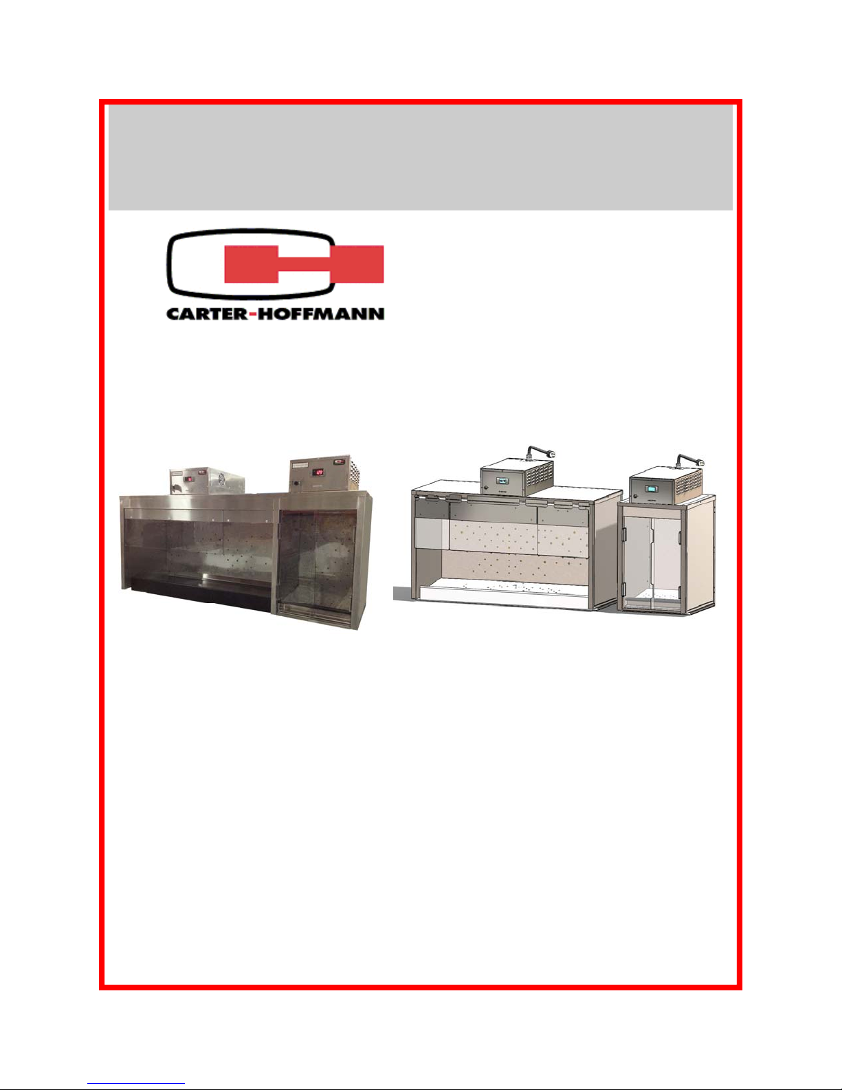
FOOD HOLDING STATIONS
MODELS: EVOL208, EVOR208, EVOL240, EVOR240
EVOLTSM208, EVOLTLG208, EVOLTSM240, EVOLTLG240
OWNERS / OPERATORS MANUAL
EVOR208
MANUFACTURED BY:
CARTER-HOFFMANN
1551 McCormick Avenue
Mundelein, IL 60060 U.S.A.
Phone: 847-362-5500
Fax: 847-367-8981
Toll Free: 800-421-3744
Email: TechnicalService@Carter-Hoffmann.com
EVOLTLG208
EVOLTSM208
PAGE
SAFETY PRECAUTIONS 2
FEATURES & SPECIFICATIONS 3
UNPACKING, INSPECTION & FREIGHT DAMAGE 4
INSTALLATION & STARTUP 5
CONTROL PANEL LAYOUT 6
OPERATION 6
CONTROLLER PROGRAMMING INSTRUCTIONS 7
DAILY CLEANING PROCEDURES 8
TIPS FOR CLEANING STAINLESS STEEL 9
WIRING DIAGRAM & REPLACEMENT PARTS LIST 10
TROUBLESHOOTING GUIDE 11-12
WARRANTY STATEMENT 13
Part Number: 18400-3178 Printed in The United States of America Rev4: KBA092413
TABLE OF CONTENTS
Page 2
SAFETY PRECAUTIONS
WARNING: ELECTRIC SHOCK HAZARD
WARNING
All service requiring access to non-insulated components must be performed by
qualified service personnel. Failure to heed this warning may result in severe
electric shock.
CAUTION: ELECTRIC SHOCK HAZARD
Disconnect this appliance from electrical power before performing any
maintenance or service.
CAUTION: BURN HAZARD
Exposed metal surfaces can be hot to the touch and may cause burns.
IMPORTANT SAFETY INSTRUCTIONS
When using electrical appliances basic safety precautions should be adhered to, including the following:
1) Be familiar with the appliance use, limitations and associated restrictions. Operating instructions must
be read and understood by all persons using or installing this appliance.
2) This appliance must be grounded. Connect only to properly grounded outle t.
3) Use this appliance only for its intended purpose as described in the manual.
a. This equipment is specifically designed to hold pre-cooked food at temperature.
b.
c. This equipment is not designed for industrial or laboratory use.
4) Cleanliness of this appliance and its accessories is essential to good sanitation.
This equipment is intended for use in commercial establishments only.
5) DO NOT submerge this appliance in water. This appliance is not jet stream approved. DO NOT direct
water jet or steam jet at this appliance, or at any control panel or wiring. DO NOT splash or pour
water on, in or over any controls, control panel or wiring. DO NOT use corrosive chemicals or vapors
in this appliance.
6) DO NOT store this appliance outdoors. DO NOT use this product near water – for example,
near a kitchen sink, in a wet basement, or near a swimming pool, and the like.
7) DO NOT operate this appliance if it has a damaged cord or plug, if it is not working properly, or if it has
been damaged or dropped. Do not immerse cord or plug in water, keep cord away from heated
surfaces, and do not let cord hang over edge of table or counter.
8) DO NOT cover or block any openings on the appl iance.
9) Only qualified service personnel should service this appliance.
NOTE: The technical content of this manual, including any wiring diagrams, schematics, parts br eakdown
illustrations and/or adjustment procedures, is intended for use by qualified technical personnel and is
subject to change without notice.
2
Page 3
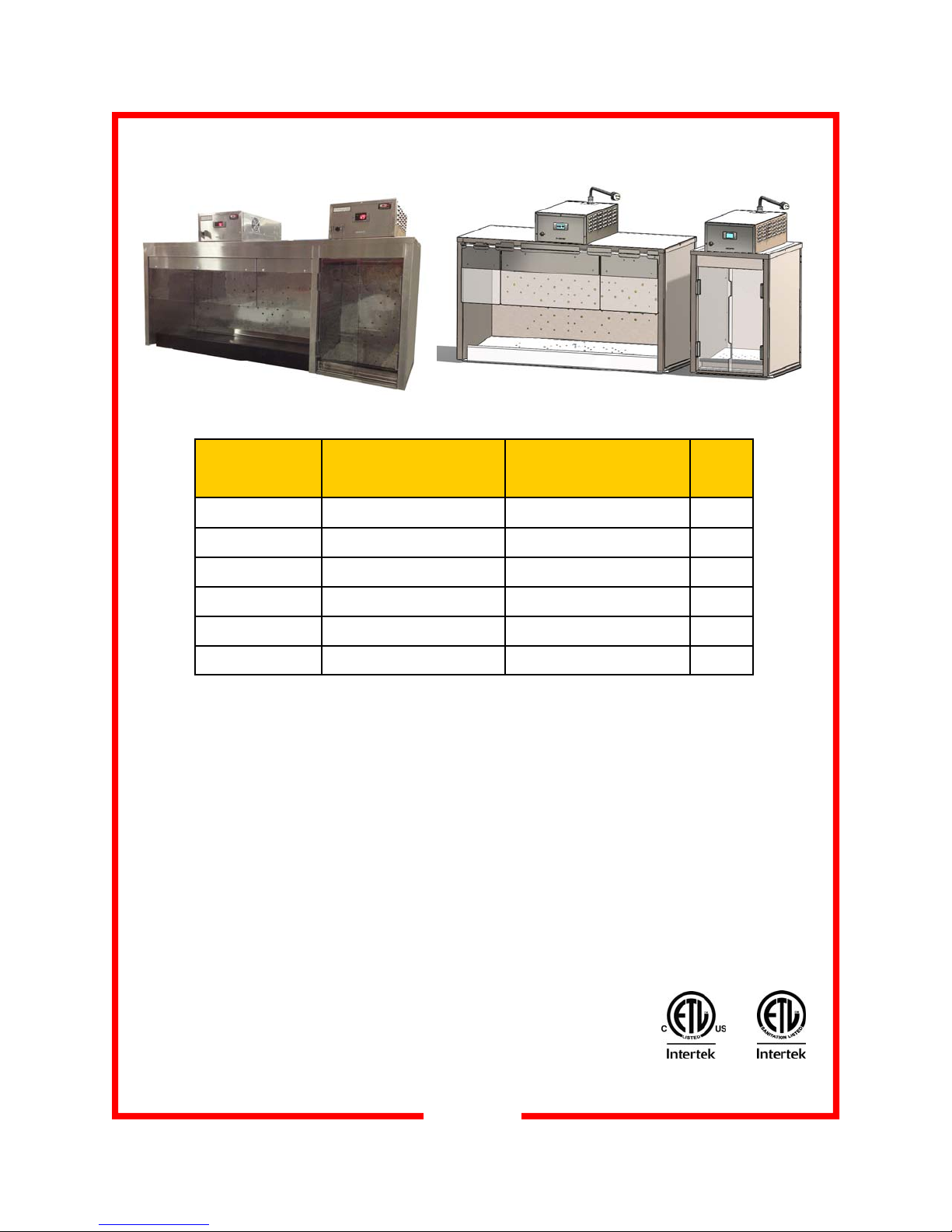
FEATURES & SPECIFICATIONS
EVOR208
Model Overall
Dimensions
EVOLTLG208
Electrical
Information
EVOLTSM208
Shipping
Weight
(each heater)
EVOL240 & EVOR240 32.38”H x 19.83”D x 62.25W 240V, 2400W, 10.5A, 50/60Hz, 1Ph 250 lbs
EVOL208 & EVOR208 32.38”H x 19.83”D x 62.25W 208V, 2400W, 12A, 50/60Hz, 1Ph 250 lbs
EVOLTSM208 32.38 x 19.83 x 17.5 208v, 2400W, 12A, 50/60Hz, 1 Ph 85
EVOLTLG208 32.38 x 19.83 x 46 208v, 2400W, 12A, 50/60Hz, 1 Ph 168
EVOLTSM240 32.38 x 19.83 x 17.5 240V, 2400W, 10.5A, 50/60Hz, 1Ph 85
EVOLTLG240 32.38 x 19.83 x 46 240V, 2400W, 10.5A, 50/60Hz, 1Ph 168
Features & Benefits
EVOL208, EVOR208, EVOL240, EVOR240. EVOR models have the small heating cabinet on the right side.
EVOL models have the small heating cabinet on the left side.
EVOLT models have separate small and large side cabinets.
Precision-engineered heat ducts with blower fan for even heat distribution throughout cabinet.
Each side individually heated with separate, removable heating units. Digitally controlled and monitored tem-
perature, with digital temperature read-out; pre-set factory temperatures of 208°F for small warming box and
158°F for large warming box. On/Off toggle switch on each heater.
Designed for over-counter use with angled interior floor.
Rod-type wire rack holders (NOT INCLUDED) are removable for cleaning.
Rear and bottom duct assemblies are removable for cleaning.
Polycarbonate shields over top of opening with flip up feature on large warming box and sliding doors on
small warming box enhance heating operation.
Supplied with 14/3 HSJO power cord and NEMA L6-15 plug.
3
3194974
Conforms with
UL STD 197
3194974
Conforms with
NSF/ANSI
STD 4
Page 4
UNPACKING AND INSPECTION
This appliance
should be
thoroughly
cleaned prior to use.
See the CLEANING
INSTRUCTIONS in
this manual.
NOTE: DO NOT discard
the carton or other
packing materials until
you have inspected the
appliance for hidden
damage and checked it
for proper operation.
Refer to FREIGHT
DAMAGE CLAIM
PROCEDURE on
bottom of this page.
1. Remove the cabinet from shipping carton, ensuring that all packing
materials and protective plastic has been removed from the unit.
2. Inspect all components for completeness and condition.
3. If any freight damage is present, a freight claim must be filed immediately with the shipping company.
4. Freight damage is not covered under warranty.
5. Check to insure all components are included: cabinet, instruction
packet, mounting brackets and additional accessories, where applicable.
6. Read operation instructions completely.
7. Appliance should be thoroughly cleaned before use. See CLEANING INSTRUCTIONS in this manual (page 8).
FREIGHT DAMAGE CLAIM PROCEDURE
NOTE: For your protection, please note that equipment in this shipment was carefully inspected
and packaged by skilled personnel before leaving the factory. Upon acceptance of this shipment,
the transportation company assumes full responsibility for its safe delivery.
IF SHIPMENT ARRIVES DAMAGED:
1. VISIBLE LOSS OR DAMAGE: Be certain that any visible loss or damage is noted on the freight
bill or express receipt, and that the note of loss or damage is signed by the delivery person.
2. FILE CLAIM FOR DAMAGE IMMEDIATELY: Regardless of the extent of damage. Contact
your dealer immediately.
3. CONCEALED DAMAGE: If damage is unnoticed until the merchandise is unpacked, notify the
transportation company or carrier immediately, and then file a “CONCEALED DAMAGE” claim
with them. This should be done within fifteen (15) days from the date the delivery was made to
you. Be sure to retain the container for inspection.
Carter-Hoffmann cannot assume liability for damage or loss incurred in transit, freight damage is
not covered under warranty. We will, however, at your request, supply you with the necessary
documents to support your claim.
4
Page 5

INSTALLATION and START-UP
WARNING:
Risk of personal injury
Installation procedures must be
performed by a qualified technician
with full knowledge of all applicable
electrical codes and with proper
load-bearing hardware. Failure
could result in personal injury and
property damage.
IMPORTANT:
Each power cord is 6' long
If necessary, contact a licensed
electrician to install an appropriate
15 amp electrical circuit with correct
NEMA receptacle for each heater.
DO NOT use an extension cord.
CAUTION:
Electrical Shock Hazard
The ground prong of the power
cord is part of a system designed to
protect you from electric shock in
the event of internal damage.
DO NOT cut off the large round
ground prong or twist a blade to fit
an existing receptacle.
IMPORTANT:
Not under warranty
Damage to unit due to being
connected to the wrong voltage or
phase is NOT covered by warranty.
WARNING:
Risk of personal injury
Unit is not waterproof, to avoid
electrical shock, keep unit and
counter from being submerged in
water. Do not operate if unit has
been in contact with water.
LOCATION
Read equipment manual completely before installing and operating the cabinet.
Unit must be installed by qualified service personnel only. Unit must be installed in such a fashion to bear the weight
of the cabinet when fully loaded; minimum 350 pounds.
The power connection for each heater is a grounded plug.
Electrical information for each heater is provided on the heat-
er serial tag on the front of each heater. Verify that the proper
electrical service required for this cabinet is available prior to
installation. Plug the power cords into grounded outlets with a
electrical service according to the electrical information provided on page 3.
Heater serial tag locations
Cabinet serial tag (Note
serial number if calling
for service)
GROUNDING INSTRUCTIONS
This appliance is equipped with cords having a grounding wire with
a grounding plug which must be plugged into an outlet that is
properly installed and grounded. In the event of an electrical short
circuit, grounding reduces the risk of electric shock by providing an
escape wire for the electric current.
WARNING—Improper use of the grounding can result in a risk
of electric shock. Consult a qualified electrician or service agent if
the grounding instructions are not completely understood, or if doubt
exists as to whether the appliance is properly grounded.
START-UP
1. Prior to use, thoroughly clean the interior of the unit, per
the instructions in this manual (page 8).
2. Plug the power cord of the cabinet into grounded outlets
with a electrical service according to the electrical information provided on page 3. Set POWER switches to the
“ON” position.
3. Do not load product into the cabinet. Allow the heat to
remove any residual oils which may adhere to inside metal surfaces. A slight emission of smoke is common during the first few hours of operation.
5
Page 6

EVOR208
CONTROL PANEL LAYOUT
Controllers
On/Off Toggle
Switches
OPERATION
AUX Key
(inoperable)
aux
Set Key
Press and release
to display temperature set point
CAUTION:
HOT SURFACE
Inner surfaces of the unit
will be very hot during and
after operation. Avoid
touching the cabinet when
loading or removing
product.
Up Arrow Key
Press to increase temperature set point
Digital Display
(1° increments)
Readout
Down Arrow Key
Press to decrease temperature set point
(1° increments)
1. Turn the power switches ON and let cabinet preheat for 30
minutes. When the cabinet is turned on, the air heater will operate until the cabinet reaches the air temperature setpoint. Each
display will read the actual temperature.
The temp icon will be illuminated when the cabinet temperature
is below the air temperature setpoint.
2. To view the temperature setpoint, press and release the SET
key.
3. After preheat, load cabinet with food product. Food is held in
various pan sizes as indicated by the spacing of the wire racks
inside the cabinet.
4. When cabinet is not in use, turn power off.
5. Cabinet must be cleaned daily. See cleaning instructions on
page 8.
6
Page 7

CONTROLLER PROGRAMMING INSTRUCTIONS
AUX Key
(inoperable)
aux
Up Arrow Key
Press to increase temperature set point
(1° increments)
Set Key
Press and release
to display temperature set point
Down Arrow Key
Press to decrease temperature set point
(1° increments)
Each controller has been factory pre-set for an air temperature set point and a low temperature alarm set point.
In most cases, these set points will not need to be changed. However, if changes are necessary, the controller is
programmable.
Factory Preset Set Points Large Side Heater Small Side Heater
Air Temperature
Low Temperature Alarm*
Air Temperature Operating Range
*Note: If Air Temperature is programmed to another setting, the Low Temperature Alarm Setting will automatically be reset 25 degrees below the Air Temperature setting.
To Lock or Unlock the Controller: Press and hold both Arrow Keys at the same time for at least three seconds. “oF” will display when the controller is locked; “oN” will display when the controller is unlocked.
To View the Temperature Set Point: Press and release the SET button
To Change the Temperature Set Point: Turn power ON. Press and hold the SET button for 3 seconds. The
current set point will display and “°F” will flash. Push the up or down arrow buttons to raise or lower the temperature set point in 1° increments. Push SET to store the new setting; the new temperate setting will flash 3 times
and then the display will revert back to the actual temperature. (If set button is not pushed within 13 seconds, the
new setting will be automatically set and the display will revert back to the actual temperatur e).
To Change from °F to °C, contact factory.
158°F 208°F
25°F below set point 25°F below set point
145° to 185°F 165° to 220°F
7
Page 8

DAILY CLEANING PROCEDURES
CAUTION:
ELECTRIC SHOCK
HAZARD
Disconnect appliance from
electric power before cleaning.
CAUTION:
HOT SURFACE
Exposed surfaces can
be hot to the touch
and may cause burns. Allow
appliance to cool before cleaning.
IMPORTANT:
DO NOT spill or pour
water into controls,
control panel or wiring. Water
damage is not covered by the
warranty.
CAUTION:
Beware of sharp edges with sheet metal
during cleaning process.
CAUTION:
Do not use steel wool
pads to clean cabinet.
Ferrous deposits will cause
rusting; roughness of the pad
will scratch the black powder
coating on the front door frame.
1. After all food products have been removed from the cabinet,
turn the power switches to “OFF” and allow the cabinet to
cool. If cabinet is supplied with a plug, disconnect from power prior to cleaning.
2. Remove the pan rack assemblies and clean according to
manufacturer’s directions.
3. Remove the doors from the large cabinet by flipping up and
lifting off. To remove the doors from the smaller cabinet, first
remove the front door by lifting the door up and out of the
track. Then remove metal track divider that is located between the doors. Lastly, lift the rear door up and out of the
track. Doors should be washed with a clean damp cloth and
chlorine-free detergent. Rinse thoroughly with clean damp
cloth and allow to dry. Do not use abrasive cleaners, waxes,
car polish, or substances containing strong aromatic solvents or alcohol. Do not use scratch pads or steel wool on
the plastic doors. Do not use stainless steel cleaner.
4. Remove bottom heat duct and then remove the rear heat
duct in each cabinet. Using a clean damp cloth with appropriate cleaner (see page 9), clean the inside of the unit and
the removed parts. Wipe any residue with clean damp cloth.
Reinstall all parts when they are dry and clean.
5. Inspect and clean the areas where there are vents or filters,
making sure no water gets into the internal controls or electrical areas of the cabinet.
6. Plastic control panel should be washed with a clean damp
cloth and chlorine-free detergent. Rinse thoroughly with
clean damp cloth and allow to dry. Do not use abrasive
cleaners, waxes, car polish, or substances containing strong
aromatic solvents or alcohol. Do not use stainless steel
cleaner.
8
Page 9

TIPS FOR CLEANING STAINLESS STEEL
RECOMMENDED TIPS FOR CLEANING STAINLESS STEEL
Purpose Frequency Cleaning Agent Method of Application
Routine Daily Soap, ammonia Sponge with cloth, rinse with clear water
cleaning detergent and water and wipe dry.
Smears/ As Stainless steel cleaner Rub with soft cloth as directed on package.
Fingerprints needed or similar products Rub in direction of grain of stainless steel.
Do not use on vinyl trim.
Stubborn Daily Any chloride-free Apply with damp sponge or cloth. Rub in
spots and as or direction of grain of stainless steel. Rinse
stains needed phosphate-free thoroughly, especially if cleaner contains
cleaner chlorine bleach, do not use on vinyl trim.
Hard water Daily Vinegar Swab with cloth.
spots as needed Rinse with water and wipe dry.
CAUTION:
Cleansers, detergents, degreasers, sanitizers, or bleaching agents that contain chlorides or phosphates will
cause permanent damage to stainless steel products. The damage appears as pits, eruptions, voids, small
holes, severe discoloration or dulling of the metal finish.
Water with high chloride content can also damage stainless steel. If unsure of your water quality, we recommend you have it tested. THIS DAMAGE IS PERMANENT, COSTLY TO REPAIR, AND IS NOT COVERED BY THE WARRANTY.
9
Page 10

WIRING DIAGRAM
REPLACEMENT PARTS LIST
PART NUMBER DESCRIPTION
18600-0042 Hi Limit 120°F Snap Disc
18600-0046 Hi Limit 350°F Auto
18602-0031 Switch Boot
18602-0083 DPDT Toggle Switch
18612-0135 Heat Element 240V/2400W
18612-0149 Heat Element 208V/2400W
18614-0275 Fan Grill
18614-0323 Muffin Fan, 230V
18614-0360 Motor, 115/230V
18616-9996 Cord Grip
18614-0321 Blower Wheel
18616-0035
PART NUMBER DESCRIPTION
18600-0117 Fan Safety Hi Limit 160°F w/Reset Snap Disc
18616-0366 Dixell 208V/16A 208°F Set-point Controller
18616-0367 Dixell 208V/16A 158°F Set-point Controller
16090-3594 HSJO 14/3 Cord with L6-16P Plug
18616-0035 20” Probe for EVO Heater
16095-3480 Sliding doors for small warming cavity (one
front and one back door)
16095-3532 Three-door flip up assembly (left)
16095-3531 Three-door flip up assembly (right)
10
Page 11

TROUBLESHOOTING GUIDE
EVO Heater: 208VAC and 240VAC. Reference connections on wiring diagram (previous page)
WARNING: All operations must be performed to requirements of NFPA-70E (Standard for
Electrical Safety in the Workplace) by a qualified electrician. CALL FOR SERVICE.
Symptom Possible Cause Remedy
No power; Dixell temperature controller display is
Switch is not in ON position
Turn the switch ON
not lit
Unit is not plugged in Plug in the power cord
Circuit breaker tripped Reset the circuit breaker. If it trips again, disconnect the EVO heater
and reset once more. When it trips, call an electrician to replace the
breaker or replace the feeder.
Otherwise, investigate for a short in the heater. Test:
1. Heating element
A. 208V - 18 Ω
B. 240V - 24Ω
Replace if the difference is significant.
2. Bower motor—replace if necessary.
Advice: When testing the motor, please pay attention to: body temperature (may be very hot!), rotor side wobbling, jammed rotor, partial or
complete winding shortage.
Power cord or plug is de-
Replace or repair
fective
Main switch is defective Replace it
Dixell temperature controller display is not lit,
but cooling fan is running
Defective thermostat Dixell Check wires for crimping or looseness—correct if necessary
Check wire connection on thermostat terminals #5 and #6—correct
connection or replace the thermostat
Dixell temperature con-
Cooling fan is not running 1. Check the fan’s cable connection-correct if necessary
troller display is not lit
Dixell Temperature con-
Heating element is cold 1. Check wires for crimping or loose connection—correct if necestroller display is lit, but
the food chamber is not
heated
Heating element is hot.
CAUTION: Heating ele-
ment may reach tempera-
ture as hot as 650°F.
2. Cooling fan is defective—replace if necessary
sary
2. Check wire connections on Dixell temperature controller terminals
#8 and #9—correct loose connection
3. Check Dixell temperature controller—replace if necessary
4. Check Hi Limit 350°F—correct connection or replace Hi Limit if
necessary
5. Check heating element (see above) - replace the element if defective
6. Check Hi Limit 160°F. If the Hi Limit reset button has popped up,
figure out reason, repair and reset.
1. Blower fan is loose—tighten set screw or replace
2. Check blower motor:
A. Motor is very hot: overheat protection activated; figure out why
motor has overheated, correct it, cool down motor. Replace if the
motor is faulty.
B. Motor is cold: correct connections or replace motor or
capacitor if necessary.
11
Page 12

TROUBLESHOOTING GUIDE - Continued
Symptom Possible Cause Remedy
Dixell temperature controller display is lit up
and food chamber is
overheated
Cooling fan does not
operate
No heat Heater blower not running,
Heating element is hot.
CAUTION: Heating element may reach temperature as hot as 650°F
Cooling fan does not operate
heating element not ener-
gized. WARNING: heater
blower may have failed
1. Hi limit 350°F is always closed: measure temperature on it surface; replace Hi Limit if it is hotter than 325°F. NOTE: When the
cover is open, the wire compartment, including the Hi Limit 350°F
is naturally cooled.
2. Dixell temperature controller is defective; replace controller
1. Check Hi Limit 120°F—replace if necessary
2. Check cooling fan—replace if necessary. NOTE: The fan is con-
trolled by Hi Limit of 120°F and starts when the temperature in
the wire box is higher than 120°F. This can take up to 6 minutes.
Also, the fan might run after turning the switch OFF, until the tem-
perature falls under 120°F.
1. Remove cover, press Hi Limit reset button on “FAN SAFETY” limit
(Part Number: 18600-0117)
2. Check operation of heater blower; replace if necessary. NOTE:
this Hi Limit prevents an “over temp” situation INSIDE the control
unit. Ensures proper air flow throughout heater and cooling fan
operation.
Temperature Controller Alarms—CONTACT SERVICE IF YOU SEE ANY OF
THESE ALARM CODES ON THE DISPLAY
Display Reads Indicates
P1 Air probe failure
HA Maximum temperature alarm
LA Low temperature alarm
EA External alarm
For technical assistance with troubleshooting, call
Carter-Hoffmann at (800)421-3744 or (847)362-5500.
NOTE: Prior to calling for service locate the serial tag on the cabinet. You will need the serial
number of the cabinet for proper identification.
Cabinet serial tag
12
Page 13

WARRANTY
Carter-Hoffmann Warranty:
Carter-Hoffmann (“CARTER-HOFFMANN”) warrants to the initial purchaser of its standard Carter
Line Products that CARTER-HOFFMANN will, at its option, repair or replace, during the warranty
period set forth below, any part of such products made necessary due to a defect in material or workmanship which is present when the product leaves its factory and which manifests itself d ur ing th e warranty period under normal use and service.
This warranty applies only to original equipment owned and possessed by the initial purchaser and the
warranty period begins on the date of installation for three years on parts an d l ab or.
Repair or replacements under this warranty will be performed, unless otherwise authorized in writing
by CARTER-HOFFMANN, at its factory. All parts or components to be repaired or replaced under this
warranty are to be shipped prepaid to CARTER-HOFFMANN, with reimbursement credit for such part
or component to be given if found by CARTER-HOFFMANN to be defective.
CARTER-HOFFMANN neither makes nor assumes and does not authorize any other person to make or
assume any obligation or liability in connection with its pro ducts other than that covered in this warranty. This warranty applies only within the continental United States and Canada. In Alaska and Hawaii, this warranty applies only to and is limited to the supply of replacement parts.
Warranty Exclusions and Limitations:
Any implied warranty of merchantability or fitness for a particular purpose is hereby specifically dis-
claimed by CARTER-HOFFMANN. There are no warranties, expressed or implied, which extend be-
yond the description on the face hereof. This warranty does not cover and CARTER-HOFFMANN shall
not under any circumstances be liable for any incidental, consequential or other damages (such as in-
jury to persons or property, loss of time, inconvenience, loss of business or profits, or other matters not
specifically covered) arising in connection with the use of, inability to use, or failure of these products.
Specifications subject to change through product improvement and innovation.
Phone: 847-362-5500 Toll free: 800-421-3744 Fax: 847-367-8981
Sales and Marketing E-mail: sales@carter-hoffmann.com
Service E-mail: technicalservice@carter-hoffmann.com
Company Website: www.carter-hoffmann.com
Carter-Hoffmann
1551 McCormick Ave.
Mundelein, Illinois, 60060 USA
13
 Loading...