

Page 1
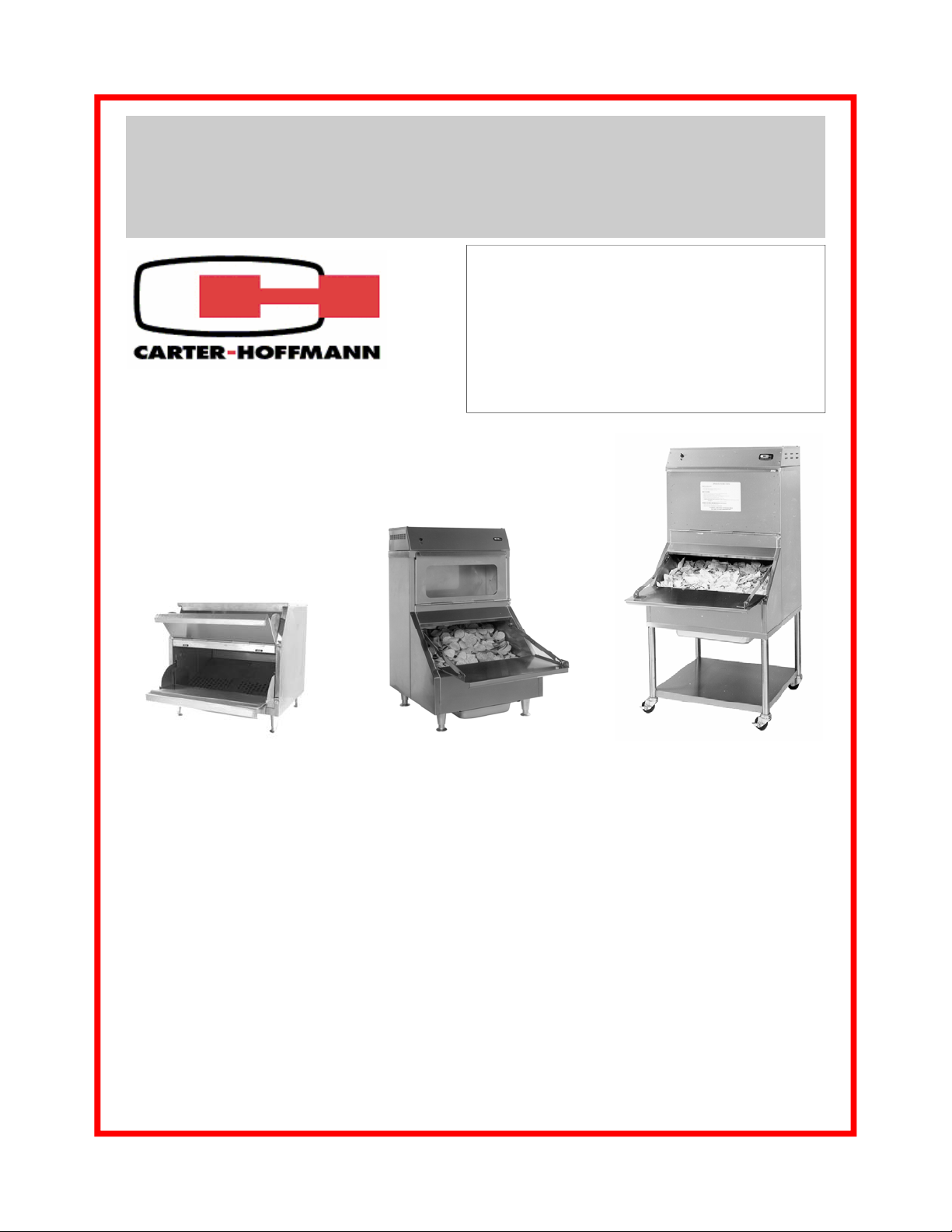
OWNERS / OPERATORS MANUAL
for
Nacho Chipwarmers
Models: CW -1, CW-2 and CW-4
Since 1947, Equipment That Delivers!
MANUFACTURED BY:
CARTER-HOFFMANN
1551 McCormick Avenue
Mundelein, IL 60060 U.S.A.
Phone: 847-362-5500
Fax: 847-367-8981
Toll Free: 800-323-9793
Email: Service@Carter-Hoffmann.com
CW-1
TABLE OF CONTENTS
CW-2
CW-4
SAFETY PRECAUTIONS……………………………..……….. 2
FEATURES & SPECIFICATIONS………..……………..……. 3
UNPACKING AND INSPECTION…………………………….. 4
INSTALLATION …………………….………………………….. 5
STARTUP……………………………………………………….. 6
NORMAL OPERATION……………………...…………………. 6
THERMOSTAT AND THERMOMETER CALIBRATION……. 7
DIGITAL CONTROL PROGRAMMING………………………. 8-9
REGULAR CLEANING PROCEDURES………………..……. 10
MONTHLY CLEANING PROCEDURES……………………… 11
WIRING DIAGRAMS…………………………………………… 12-13
TROUBLESHOOTING GUIDE ……………………………….. 14
WARRANTY STATEMENT……….……………….………….. 15
Part Number: 18400-3051b Printed in The United States of America Rev: 071708JJO
Page 2
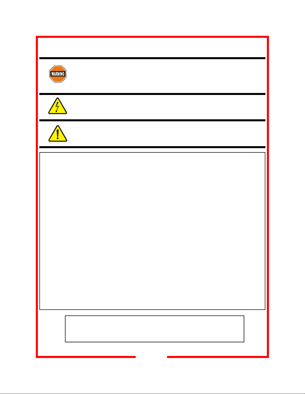
SAFETY PRECAUTIONS
WARNING: ELECTRIC SHOCK HAZARD
All service requiring access to non-insulated components must be performed by
qualified service personnel. Failure to heed this warning may result in severe
electric shock.
CAUTION: ELECTRIC SHOCK HAZARD
Disconnect this appliance from electrical power before performing any
maintenance or service.
CAUTION: BURN HAZARD
Exposed metal surfaces can be hot to the touch and may cause burns.
IMPORTANT SAFETY INSTRUCTIONS
When using electrical appliances basic safety precautions should be adhered to, including the following:
1) Be familiar with the appliance use, limitations and associated restrictions. Operating instructions must
be read and understood by all persons using or installing this appliance.
2) This appliance must be grounded. Connect only to properly grounded outle t.
3) Use this appliance only for its intended use as described in the manual.
a. This equipment is specifically designed to hold pre-cooked food at temperature.
b.
c. This equipment is not designed for industrial or laboratory use.
4) Cleanliness of this appliance and its accessories are essential to good sanitation.
This equipment is intended for use in commercial establishments only.
5) DO NOT submerge this appliance in water. This appliance is not jet stream approved. DO NOT direct
water jet or steam jet at this appliance, or at any control panel or wiring. DO NOT splash or pour
water on, in or over any controls, control panel or wiring. DO NOT use corrosive chemicals or vapors
in this appliance.
6) DO NOT store this appliance outdoors. DO NOT use this product near water – for example,
near a kitchen sink, in a wet basement, or near a swimming pool, and the like.
7) DO NOT operate this appliance if it has a damaged cord or plug, if it is not working properly, or if it has
been damaged or dropped. Do not immerse cord or plug in water, keep cord away from heated
surfaces, and do not let cord hang over edge of table or counter.
8) DO NOT cover or block any openings on the appliance.
9) Only qualified service personnel should service this appliance.
NOTE:
The technical content of this manual, including any wiring diagrams, schematics, parts
breakdown illustrations and/or adjustment procedures, is intended for use by qualified
technical personnel and is subject to change without notice.
2
Page 3
FEATURES & SPECIFICATIONS
Features & Benefits
• Gentle, even heating—our exclusive heat duct and baffle system forces air down rear wall duct and up
through the chips. No hot or cold spots - and no burned chips!
• Top-mounted heating system — all components easily accessible for service and located away from chip
dust, crumbs and oils.
• Serving door flips down for a handy shelf to set baskets while serving.
• Factory pre-set temperature of 180°F (79°C). Adjustable thermostat.
• Pull-out crumb pan for easy cleaning.
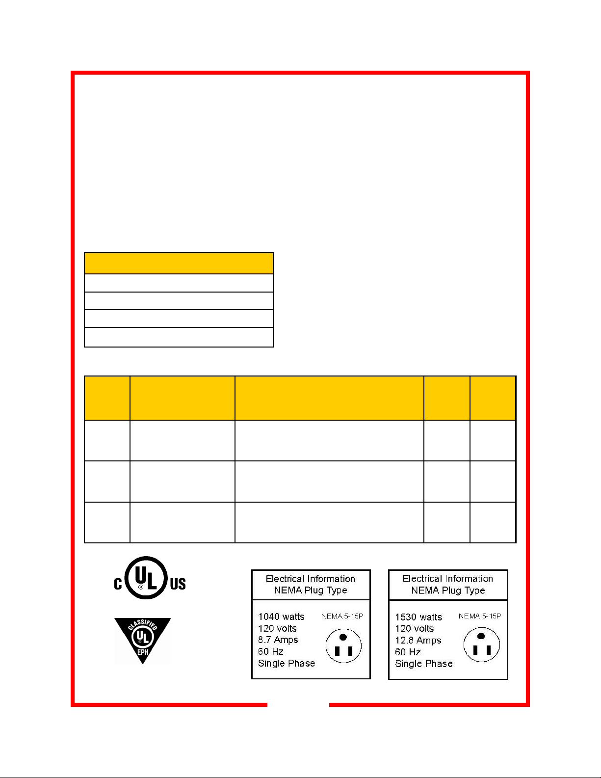
OPTIONS AND ACCESSORIES
220 or 240 volt operation
2” casters (CW1 only)
Rolling stand
Clear polycarbonate doors
*Height includes 4” for legs. Ordering optional casters (CW1), or rolling stands (CW2, CW4) will alter height.
Model
Number
CW1 2.75 20 27-1/4 25-1/2 28-3/8
CW2 3.00 22 38-3/4 23 22-3/4
CW4 5.75 44 45-1/2 28 29-5/8
Chip Capacity
Cubic feet Gallons
(692) (648) (721)
(984) (584) (578)
(1156) (711) (752)
Overall Dimensions
Height * Depth Width
in (mm)
Legs
in (mm)
4
(102)
4
(102)
4
(102)
Class 100
Shipping
Weight
lbs (kg)
135
(61)
154
(69)
245
(111)
CW1 CW2 & CW4
3
Page 4
UNPACKING AND INSPECTION
This appliance
should be
thoroughly
cleaned prior to use.
See the CLEANING
INSTRUCTIONS in
this manual.
NOTE: DO NOT discard
the carton or other
packing materials until
you have inspected the
appliance for hidden
damage and checked it
for proper operation.
Refer to SHIPPING
DAMAGE CLAIM
PROCEDURE on
bottom of this page.
UNPACKING AND INSPECTION
1. Remove the cabinet from shipping carton, ensuring that all packing materials and protective plastic has been removed from the
unit. Inspect all components for completeness and condition.
2. If any freight damage is present, a freight claim must be filed immediately with the shipping company.
3. Freight damage is not covered under warranty.
4. Check to insure all components are included: cabinet, instruction
packet and additional accessories.
5. Read operation instructions completely.
6. Appliance should be thoroughly cleaned before use. See
CLEANING INSTRUCTIONS in this manual.
FREIGHT DAMAGE PROCEDURE
NOTE: For your protection, please note that equipment in this shipment was carefully inspected
and packaged by skilled personnel before leaving the factory. Upon acceptance of this shipment,
the transportation company assumes full responsibility for its safe delivery.
IF SHIPMENT ARRIVES DAMAGED:
1. VISIBLE LOSS OR DAMAGE: Be certain that any visible loss or damage is noted on the
freight bill or express receipt, and the note of loss or damage is signed by the delivery person.
2. FILE CLAIM FOR DAMAGE IMMEDIATELY
your dealer immediately.
3. CONCEALED DAMAGE: If damage is unnoticed until the merchandise is unpacked, notify the
transportation company or carrier immediately, and then file a “CONCEALED DAMAGE” claim
with them. This should be done within fifteen (15) days from the date the delivery was made to
you. Be sure to retain the container for inspection.
Carter-Hoffmann cannot assume liability for damage or loss incurred in transit, freight damage is
not covered under warranty. We will, however, at your request, supply you with the necessary
documents to support your claim.
: Regardless of the extent of damage. Contact
4
Page 5
INSTALLATION
WARNING:
Risk of personal injury
Installation procedures must be
performed by a qualified technician
with full knowledge of all applicable
electrical codes.
Failure can result in personal injury
and property damage.
IMPORTANT:
If necessary, contact a licensed
electrician to install an appropriate
15 amp electrical circuit with correct
NEMA receptacle.
DO NOT use an extension cord.
CAUTION:
Electrical Shock Hazard
The ground prong of the power cord
is part of a system designed to protect you from electric shock in the
event of internal damage.
DO NOT cut off the large round
ground prong or twist a blade to fit
an existing receptacle.
Location
For proper operation and maximum performance, locate the
unit in an ambient air temperature of 70F (21C).
Avoid placement in areas near exhaust fans where there are
active air movements.
For safe operation, locate the unit at least 2” from combustible walls and materials, on a solid level surface.
GROUNDING INSTRUCTIONS
This appliance is equipped with a cord having a grounding
wire with a grounding plug which must be plugged into an
outlet that is properly installed and grounded. In the event of
an electrical short circuit, grounding reduces the risk of electric shock by providing an escape wire for the electric current.
WARNING—Improper use of the grounding can result in
a risk of electric shock. Consult a qualified electrician or
serviceman if the grounding instructions are not completely
understood, or if doubt exists as to whether the appliance is
properly grounded.
IMPORTANT:
Not under warranty:
Damage to unit due to being
connected to the wrong voltage or
phase is NOT covered by warranty.
5
Page 6

STARTUP
CAUTION:
Risk of personal injury
Unit is not waterproof, to
avoid electrical shock
keep unit and counter
from being submerged in
water.
Do not operate if unit has
been submerged in water.
NOTE:
The cabinet temperature
is preset at the factory for
180 degrees F.
CAUTION:
HOT SURFACE
Inner surfaces of the unit
will be very hot during
and after operation.
Avoid touching the cabinet when loading or removing product.
1. Ensure all protective plastic and packaging materials have been
removed.
2. Plug the power cord of the cabinet into a grounded outlet with a
minimum 15 amp 120VAC, 60HZ, single phase electrical service.
3. Set POWER switch to “ON” position.
4. Do not load product into the cabinet. Allow the heat to remove any
residual oils which may adhere to inside metal surfaces. A slight
emission of smoke is common during the first few hours of operation.
5. Thoroughly clean the interior of the unit, per the instructions in this
manual.
NORMAL OPERATION
1. Install 12” by 20” pan under the cabinet. Cabinet performance will
be severely affected if the 12” by 20”.
2. Before using, familiarize yourself with the cabinet controls.
3. Turn the cabinet on.
4. For best results and more uniform heating, preheat the cabinet prior
to loading.
5. Wait 30 minutes for the cabinet to preheat.
IMPORTANT:
Unit must be properly
installed and cleaned
prior to use.
Please read the content
of this manual to understand the proper operation and maintenance of
this product.
6. Load the cabinet with chips.
7. Allow at least 30 minutes for the chip temperature to stabilize.
8. Serve the chips by unloading from the bottom door.
9. Use the top door to reload chips into the cabinet to ensure chips are
always hot and available.
10. At the close of the business day, perform the daily cleaning procedures.
6
Page 7

FOR UNITS WITH THERMOSTATIC CONTROLS
to increase turn set screw counter clockwise
to decrease turn set screw clockwise
NOTE:
Heating system should cycle at least
two times after the last adjustment to
achieve accurate calibration.
Set
screw
NORMAL OPERATION
THERMOSTAT CALIBRATION
If additional heat range is required in the cabinet, unplug
the heating unit, remove the thermostat knob, insert a small
straight blade screwdriver into opening in center and turn
limit control set screw counter-clockwise one full turn. See
diagram on left.
Replace thermostat knob and turn clockwise to reach new
maximum temperature. Repeat this until desired temperature is reached. Each 1/4 turn of the calibration set screw
will raise the element heating capacity by approximately 2535ºF.
If a reduction of heat is desired, turn limit screw clockwise
one full turn. Hold the door open allowing unit to cool until
inside temperature is below the desired temperature.
Close the door and allow unit to rise to a new maximum
temperature. Repeat this until desired temperature is
reached.
THERMOMETER CALIBRATION
Place an oven thermometer or accurate temperature meter
in the geometric center of the cabinet. Power heating system up and turn thermostat clockwise, to maximum setting
and wait approximately 45 minutes.
Open the door and check inside thermometer temperature.
In recalibration is required, pry the plastic cover off the dial
body and with a small flat blade screwdriver, insert into the
pointer as shown.
Carefully turn the pointer with your finger to match the stabilized internal temperature. Be careful not to bend the
pointer, as it is very fragile.
7
Page 8

Default values
-temp set point =180F
-operating range=140-200F
-low temp alarm = 140F
--temp scale = F
NORMAL OPERATION
FOR UNITS WITH DIGITAL CONTROLS
Heat on
indicator light
Alarm reset
Temperature
set button
NOTE : controllers
without the decal so button positions need to be noted for programming.
To View or Change the Temperature set point:
Turn the power on. To view the temperature set point, press and
hold the temperature set button. To change the temperature set
point, press and hold the temperature set button, press the up or
down arrow button until the desired air temperature is displayed.
The display will advance in 1° increments. Turn off the power to the
cabinet to save the changes in the controller memory.
To View or Change Alarm set point:
Turn the power on. To view the alarm set point, press and hold the
alarm-reset button. To change the alarm set point, press and hold
the alarm-reset button, press the up or down arrow button until the
desired alarm temperature is displayed. The display will advance
in 1° increments. Turn off the power to the cabinet to save the changes
in the controller memory.
To View or Change Temperature Scale:
The cabinet is programmable for a temperature scale in degrees
Fahrenheit and Centigrade (Celsius). With the cabinet power off,
press and hold the UP and DOWN arrow buttons. Turn power
back on while holding both arrows. Display will show current scale
(C or F). If desired, push the up or down arrow to change the
scale. Turn off the power to the cabinet to save the changes in the con-
troller memory.
Digital display
readout
Up & down
adjustment
arrows
may be are used
8
Page 9

Default values
-temp setpoint =180F
-operating range=140-200F
-low temp alarm = 140F
--temp scale = F
DIGITAL CONTROL
Alarm
set
165
Temp
set
Up
arrow
Down
arrow
NORMAL OPERATION
PROGRAMMING INSTRUCTIONS:
FOR UNITS WITH DIGITAL CONTROLS
Changing the Temperature Range:
The temperature range is the range that the cabinet is designed to operate within. With the cabinet power off, press and hold the UP and
DOWN arrow buttons. While still holding in the arrow buttons, turn
back on the power to the cabinet. The display will read: Ser F and
then F (if temperature scale is set to F) will display.
To change the range, press and release the TEMP SET button. The
display will read: rLo and then the current low temperature range set
point. To change the temperature, press the UP or DOWN arrows
until the desired temperature is displayed. The low setting should be
set to 140°F.
Press the TEMP SET button again. The display will read Rhi. and
then the current high temperature range set point. To change the temperature, press the UP or DOWN arrows button until the desired temperature is displayed. The high setting should be set to 200°F. Turn
off the power to the cabinet to save the changes in the controller memory.
Changing the Alarm Range:
The alarm range is the range that the low temperature alarm is designed to operated under. The alarm range should be programmed
for 140°F Maximum and 65°F Minimum. The cabinet low temperature alarm can be programmed to operate within these two set points.
With the cabinet power off, press and hold the UP and DOWN arrow
buttons. While still holding in the arrow buttons, turn back on the
power to the cabinet. The display will read: Ser F and then F will display. (if temperature scale is set to F) To change the range, press and
release the ALARM RESET button. The display will read ALo and
then the current low alarm temperature set point. To change the low
alarm temperature, press the UP or DOWN arrows until the desired
temperature is displayed. The low setting should be set to 65°F.
Press the ALARM RESET button again. The display will read AHi and
then the current high alarm temperature set point. To change the high
alarm temperature, press the UP or DOWN arrows until the desired
temperature is displayed. The high setting should be set to 140°F.
Turn off the power to the cabinet to save the changes in the controller memory.
9
Page 10

DAILY CLEANING PROCEDURES
CAUTION:
ELECTRIC SHOCK
Disconnect appliance from
electric power before cleaning.
HAZARD
CAUTION:
HOT SURFACE
Exposed surfaces can be hot
to the touch and may cause
burns. Allow appliance to cool
before cleaning.
IMPORTANT:
DO NOT spill or pour
water into controls,
control panel or wiring. Water
damage is not covered by warranty.
CAUTION:
Beware of sharp edges on
sheet metal during cleaning.
1. Turn the power switch to “OFF” and allow the cabinet to cool.
2. Unplug the unit prior to any cleaning.
3. Remove all leftover chips from the cabinet, and store for future
use.
4. Remove the two bottom chip covers. (see figure 1.)
5. Brush any crumbs down into the bottom 12” x 20” clean out
pan.
6. Remove and clean the chip crumb pan from the bottom of the
unit by sliding it out towards the operators side of the unit.
Clean the pan, dry thoroughly and replace, see figure 2
7. After cleaning and sanitizing, rinse all exposed surfaces with
clean water, ensuring no water reaches any electrical areas.
8. Replace the bottom chip covers.
9. The unit is now ready to be used for the next business day.
NOTE: This equipment has been
designed and manufactured to
meet all applicable health and
safety codes and will give years of
dependable service if used properly.
All cabinets should be thoroughly
cleaned before using.
10
Page 11

MONTHLY CLEANING PROCEDURES
CAUTION:
ELECTRIC SHOCK
HAZARD
Disconnect appliance from
electric power before cleaning.
IMPORTANT:
DO NOT spill or pour
water into controls,
control panel or wiring. Water damage is not cov-
ered by warranty.
CAUTION:
Beware of sharp
edges on sheet
metal during cleaning, especially during removal the
grease filters
Cleansers, detergents, degreasers, sanitizers, or bleaching agents that contain chlorides or
phosphates will cause permanent damage to stainless steel products. The damage appears
as pits, eruptions, voids, small holes, severe discoloration or dulling of the metal finish.
Water with high chloride content can also damage stainless steel.
CAUTION: If unsure of your water quality, we recommend you have it tested.
THIS DAMAGE IS PERMANENT, COSTLY TO REPAIR, AND IS NOT COVERED
BY THE WARRANTY.
1. Follow steps 1 through 5 from the daily cleaning instructions
(previous page).
2. Remove heat duct from inside back of cabinet by lifting upwards and towards front of cabinet.
3. Clean cabinet interior with soap and water. Use a bristle
brush to clean around the (4) bolts located on the back wall.
4. Replace the heat duct, locating the (4) holes in the heat duct
over the (4) bolts on the inside back of the cabinet and slide
the duct down to secure it in place.
5. Replace the clean slanted bottom pieces inside the cabinet,
and the clean 12” x 20” pan at the bottom of the cabinet.
RECOMMENDED TIPS FOR CLEANING STAINLESS STEEL
Purpose Frequency Cleaning Agent Method of Application
Routine Daily Soap, ammonia Sponge with cloth, rinse with clear water
cleaning detergent and water and wipe dry.
Smears/ As Stainless steel cleaner Rub with soft cloth as directed on package.
Fingerprints needed or similar products Rub in direction of grain of stainless steel.
Do not use on vinyl trim.
Stubborn Daily Any chloride-free Apply with damp sponge or cloth. Rub in
spots and as or direction of grain of stainless steel. Rinse
stains needed phosphate-free thoroughly, especially if cleaner contains
cleaner chlorine bleach, do not use on vinyl trim.
Hard water Daily Vinegar Swab with cloth.
spots as needed Rinse with water and wipe dry.
11
Page 12

12
Page 13

13
Page 14

TROUBLESHOOTING GUIDE
SYMPTOM POSSIBLE CAUSE SUGGESTED REMEDY
No power to unit Not plugged in or circuit breaker tripped Check or reset circuit breaker
Connect to proper receptacle
Power cord damaged Check - replace if required
Power switch damaged or defective Check - replace if required
Product dries out too
quickly
Unit is on, motors are
running but no heat
Takes too long to get
to temperature
Unit is hot
but low or no airflow
NOTE:
The technical content of this manual,
including any wiring diagrams, schematics, parts breakdown illustrations and /
or adjustment procedures, is intended
Operation where product temp is too high Check product temps going into holding
Thermostat incorrectly set or defective Check proper operation or calibration of
Internal wiring error
Element hi-limit trip / defective Call service technician
Improper voltage Call service technician to verify in-
Internal wiring error Call service technician
Circulation motor has quit Call service technician
Improper voltage Call service technician to verify in-
NOTE:
For warranty service, call Carter-Hoffmann
direct at 800-323-9793 for authorization,
we will dispatch the nearest authorized
service agency.
for use ONLY by qualified technical
personnel
.
cabinet
thermostat
Call service technician
coming voltage matches cabinet specifications.
coming voltage matches cabinet specifications.
14
Page 15

WARRANTY
Carter-Hoffmann Warranty:
Carter-Hoffmann (“CARTER-HOFFMANN”) warrants to the initial purchaser of its standard Carter
Line Products that CARTER-HOFFMANN will, at its option, repair or replace, during the warranty
period set forth below, any part of such products made necessary due to a defect in material or workmanship which is present when the product leaves its factory and which manifests itself d ur ing th e warranty period under normal use and service.
This warranty applies only to original equipment owned and possessed by the initial purchaser and the
warranty period begins on the date of original shipment from the CARTER-HOFFMANN factory and
extends as follows: to component parts and labor for 12 months; to refrigeration compressor unit for
one year (limited to replacement only - not to include labor for removal, repair or replacement).
Repair or replacements under this warranty will be performed, unless otherwise authorized in writing
by CARTER-HOFFMANN, at its factory. All parts or components to be repaired or replaced under this
warranty are to be shipped prepaid to CARTER-HOFFMANN, with reimbursement credit for such part
or component to be given if found by CARTER-HOFFMANN to be defective.
CARTER-HOFFMANN neither makes nor assumes and does not authorize any other person to make or
assume any obligation or liability in connection with its pro ducts other than that covered in this warranty. This warranty applies only within the continental United States and Canada. In Alaska and Hawaii, this warranty applies only to and is limited to the supply of replacement parts.
Warranty Exclusions and Limitations:
Any implied warranty of merchantability or fitness for a particular purpose is hereby specifically dis-
claimed by CARTER-HOFFMANN. There are no warranties, expressed or implied, which extend be-
yond the description on the face hereof. This warranty does not cover and CARTER-HOFFMANN shall
not under any circumstances be liable for any incidental, consequential or other damages (such as in-
jury to persons or property, loss of time, inconvenience, loss of business or profits, or other matters not
specifically covered) arising in connection with the use of, inability to use, or failure of these products.
Specifications subject to change through product improvement and innovation.
Carter-Hoffmann
1551 McCormick Ave.
Mundelein, Illinois, 60060 USA
Phone: 847-362-5500 Toll free: 800-323-9793 Fax: 847-367-8981
Sales and Marketing E-mail: sales@carter-hoffmann.com
Service E-mail: service@carter-hoffmann.com
Company Website: www.carter-hoffmann.com
15
 Loading...