

Page 1
HEAT RETENTION BANQUET CART
MODELS: BR96, BR120, BR150 and BR1000
OWNER / OPERATOR’S MANUAL
PATENTED HEAT RETENTION TECHNOLOGY
US Patent Numbers
7,102,103B2 & 7,394,042
BR120
TABLE OF CONTENTS
Introduction……………………………………………....…. 2
Warranty, Warranty Exclusions and Limitations…..…..... 3
Shipping Damage and Claim Procedure………..……..... 3
Precautions and General Information …………..…....… 4
Specifications …………………………………….….….... 5
Operating Features and Controls ……………….….…... 5
Installation ………………………………………….….….. 6
Agency Listing Information ………………………..…..… 6
Cleaning …………………………………………….…….. 7
Normal Operation …………………………………..….… 8
Wiring Diagram ……………………………………..……. 9
Replacement Parts List………………………………..…. 10
Troubleshooting Suggestions ………………………...... 11
Service Expectations……………………………………… 12
Contact Information and Notes………………………..… 13
Owner Information…………………………………….….. 14
Carter-Hoffmann
1551 McCormick Ave.
Mundelein, Illinois, 60060 USA
Phone: 847-362-5500 Toll free: 800-323-9793 Fax: 847-367-8981
Sales and Marketing E-mail: sales@carter-hoffmann.com
Service E-mail: service@carter-hoffmann.com
Company Website: www.carter-hoffmann.com
Part Number: 18400-3100B Printed in the United States of America 090910KBA
Page 2
INTRODUCTION
Y
Thank you for purchasing this Carter-Hoffmann appliance. Proper installation, professional operation
and consistent maintenance of this appliance will ensure that it gives you the very best performance
together with a reliable, long lasting and economical life. This manual contains information needed
to properly install, operate and maintain this appliance
This product is the result of extensive research and field testing. The materials used were selected
to provide optimum performance, maximum durability and an attractive appearance. At CarterHoffmann, every single unit is thoroughly
inspected and functionally tested prior to
shipment.
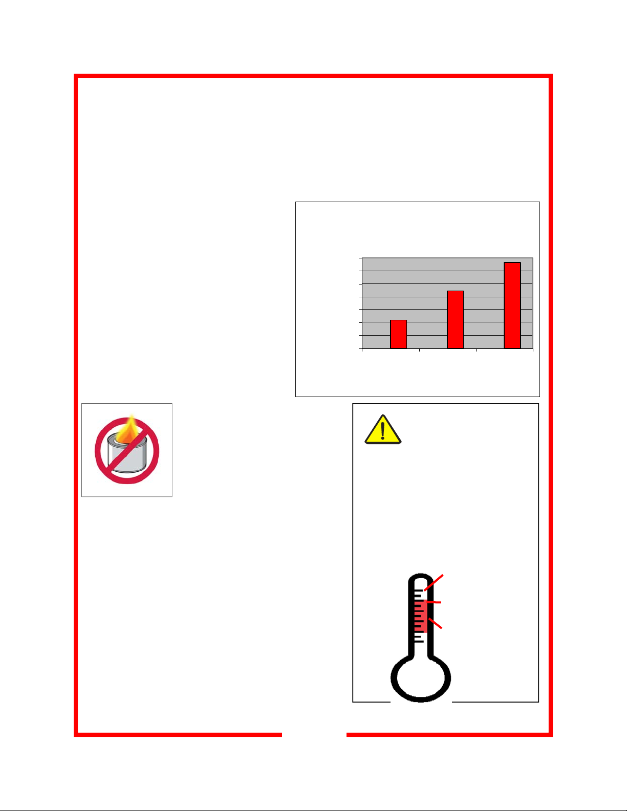
early Cost of Canned Heat Per
(4 cans per cart, per meal)
Cart
This Carter-Hoffmann cabinet provides the
Cost of Canned Heat
3500
3000
2500
2000
1500
1000
(1 can=$0.76)
500
0
123
# Meals S erved P er Day
best environment for pre-plated food products by regulating consistent the air temperature. This model uses hot circulated air (no
moisture) and heat retention technology.
Due to the retention capabilities of the heating module, this unit eliminates the need for
any type of canned fuel (i.e. “Sterno®” type
heat). This is the major benefit of this unit,
which will undoubtedly pay for itself over a
short period of time.
The major benefits of
EnduraHeat® technology are:
Safety: elimination of potential fire
hazards from fuel use reduces
the likelihood of employee burns
Cost: eliminate expense of
canned fuel; no more scorched carpeting or other
decor
Productivity: eliminate the extra labor involved to
put cans into carts as well as monitor canned heat
use
Sanitation: no open flames to scorch pans, burn
food or scorch the cabinet interior; eliminate messy
residue from canned fuel
Food Quality: no transfer of fuel fumes to ruin the
flavor of food; food is maintained serving temperature
Extended Unplugged Hold Time: Cabinet temperature remains above 140°F for 2 hours, unplugged
.
2
CAUTION: SAFE FOOD
HOLDING PRACTICES
RECOMMENDED
Cooking food to a safe temperature,
holding at a temperature of at least
140°F is critical in the prevention of
foodborne illness. Hold only cooked,
hot food at 140°F or higher. This
cabinet is not intended to cook or
reheat food. Food must be at appropriate temperature before being
placed into cabinet.
COOK TO AT LEAST
165°F Destruction of
165°F
140°F
41°F
most bacteria
HOLD at 140°F or higher
DANGER ZONE: 41°F
to 140°F Bacteria
grow rapidly
Page 3

CARTER-HOFFMANN WARRANTY
Carter-Hoffmann warrants to the initial purchaser
of its standard Carter Line Products that CarterHoffmann will, at its option, repair or replace, during the warranty period set forth below, any part of
such products made necessary due to a
product leaves its factory and which
manifests itself during the warranty period under
defect in material or workmanship which is present
normal use and
when the
service.
This warranty applies only to original equipment owned and possessed by the initial purchaser and
the warranty period begins on the date of original shipment from the Carter-Hoffmann factory and
extends as follows: to component parts and labor for one year; to refrigeration compressor unit for
one year (limited to replacement of the unit only-not to include the labor for removal, repair or replacement)
. Repair or replacement under this warranty will be performed, unless otherwise authorized in writing by Carter-Hoffmann, at its factory. All parts or components to be repaired or replaced under this warranty
are to be shipped prepaid to Carter-Hoffmann, with reimbursement credit for such part or component to be
given if found by Carter-Hoffmann to be defective.
Carter-Hoffmann neither makes nor assumes and does not authorize any other person to make or
assume any obligation or liability in connection with its products other than that covered in this warranty. This warranty applies only within the continental United States and Canada. In Alaska and Hawaii, this warranty applies only to and is limited to the supply of replacement parts.
WARRANTY EXCLUSIONS AND LIMITATIONS
ANY IMPLIED WARRANTY OF MERCHANTABILITY OR FITNESS FOR A PARTICULAR PURPOSE IS HEREBY SPECIFICALLY DISCLAIMED BY CARTER-HOFFMANN. There are no warranties, express or implied, which extend beyond the description on the face thereof.
This warranty does not cover and Carter-Hoffmann shall not under any circumstances be liable for
any incidental, consequential or other damages (such as injury to persons or property, loss of time,
inconvenience, loss of use, loss of business or profits, or other matters not specifically covered) arising in connection with the use of, inability to use, or failure of these products.
Note: Due to our continuous process of product improvement and innovation, all listed specifications
subject to change.
SHIPPING DAMAGE CLAIM PROCEDURE
NOTE: For your protection, please note that equipment in this shipment was carefully inspected and
packaged by skilled personnel before leaving the factory. Upon acceptance of this shipment, the
transportation company assumes full responsibility for its safe delivery.
IF SHIPMENT ARRIVES DAMAGED:
1. VISIBLE LOSS OR DAMAGE: Be certain that any visible loss or damage is noted on the freight
bill or express receipt, and that the note of loss or damage is signed by the delivery person.
2. FILE CLAIM FOR DAMAGE IMMEDIATELY: Regardless of the extent of the damage.
3. CONCEALED LOSS OR DAMAGE: if damage is unnoticed until the merchandise is unpacked,
notify the transportation company or carrier immediately, and file “CONCEALED DAMAGE” claim
with them. This should be done within ten (10) days from the date the delivery was made to
you. Be sure to retain the container for inspection.
4. Carter-Hoffmann cannot assume liability for damage or loss incurred in transit. We will, however,
at your request, supply you with the necessary documents to support your claim.
3
Page 4
PRECAUTIONS and GENERAL INFORMATION
CAUTION: Electric Shock Hazard
All servicing requiring access to non-insulated components must be performed by qualified service
personnel. Do not open any access panels which require the use of tools. Failure to heed this warning can result in electrical shock. Disconnect this appliance from electrical power before performing
any maintenance or servicing.
WARNING: Injury Hazard
All installation procedures must be performed by qualified personnel with full knowledge of all applicable electrical codes. Failure could result in property damage and personal injur y.
WARNING Electric Shock Hazard
Appliance must be plugged into a properly grounded receptacle to prevent possible shock hazard.
Electrical shock will cause death or serious Injury.
CAUTION: Burn Hazard
Interior surfaces of the appliance may be HOT to the touch, and can cause serious burns.
GENERAL INFORMATION
•
This appliance is intended for use in commercial establishments,
where all operators are familiar with the appliance use, limitations
and associated hazards.
•
Operating instructions and warnings must be read and understood
by all operators and users.
•
This appliance is intended for use to holding pre-plated, covered,
pre-cooked foods for human consumption. No other use is recommended or authorized by the manufacturer or its agents.
•
Cleanliness of this appliance is essential to good sanitation. Read
and follow all included cleaning instructions and schedules to ensure the safety of the food product.
•
All included trouble shooting guides, component views and parts
lists are included for general reference, and are intended for use
by qualified service personnel.
•
Knowledge of proper installation, operation and maintenance procedures is essential to ensure the safe operation of this oven.
•
Always have dry hands prior to using the piece of equipment.
•
Turn OFF the unit (not all units have power switches) anytime the cabinet is not in use.
•
If an electrical shock is felt when touching the cabinet, disconnect the power immediately and call CarterHoffmann Technical Service for assistance or service.
•
If the power cord is frayed or the plug damaged, DO NOT plug into the electrical power receptacle. If it is
already plugged in, turn off the main circuit breaker, usually located in the building’s breaker box, then disconnect the plug.
•
Disconnect the power cord before attempting any repairs to the cabinet or heating unit.
•
Repairs to this unit must be by qualified personnel.
•
DO NOT SPRAY WITH WATER OR CLEANING SOLUTIONS, or submerge the heating unit. Components
and wiring present a high shock hazard when wet.
•
Disconnect heating unit when cleaning cabinet or heating unit.
•
Both the interior and exterior surfaces of this appliance can be hot to the touch and may cause burns.
SERVICE / SAFETY
CAUTION: Equipment
Electrical Damage
DO NOT plug in or use this appliance
until all Installation Instructions are
read and followed. Damage to the
appliance may occur if these instructions are not followed.
This manual is considered to be a
permanent part of this appliance.
This manual must remain with the
appliance if it is sold or moved to
another location
.
4
Page 5
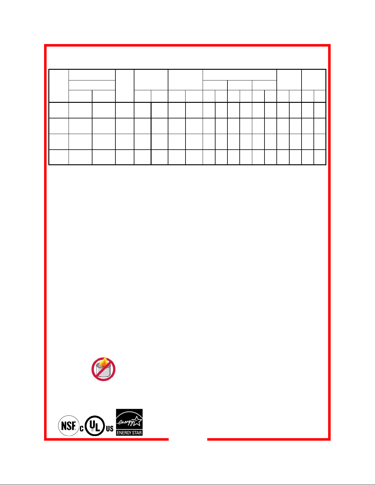
PRODUCT SPECIFICATIONS AND OPERATING FEATURES
PLATE CAPACITY
(covered only)
MODEL
NUMBER
BR96 96 N/A 3 13 1/4 337
BR120 120 N/A 3 16 1/2 419
BR150 150 N/A 3 16 1/2 419
BR1000 120 96 3 14 5/16 364 27 5/8
PLATE COVER
DIAMETER
8.75" x
11.00"
11.125" x
NUMBER
SHELVES
12.75"
CONSTRUCTION...Completely welded
double wall cabinet construction with
outer cabinet formed and welded to
base. All seams turned in to eliminate
raw edges.
CABINET MATERIAL...All stainless
steel construction with polished exterior.
BASE FRAME...12 gauge stainless
steel full depth caster bolsters with 16
gauge stainless steel square tubing
welded to bolsters.
CASTERS...6” diameter, industrial
grade casters. Sealed roller axle bearing and double ball bearing swivel.
Zerk grease fittings. Plate mounted and
bolted to base in offset “wheel ahead”
pattern. Two casters fitted with brakes.
BUMPER...Non-marking gray vinyl
bumper set in heavy-duty 3/16” thick
extruded aluminum frame with reinforced corner cutouts. Reinforced with
12 gauge angle bracket welded to cart
and bolted through bumper.
INSULATION...2” thick, high density
continuous wrap-around type fiberglass
insulation.
OF
CLEARANCE
BETWEEN
SHELVES
in mm in mm in mm in mm in mm in mm lbs kgs
22 1/8 x
47
22 1/8 x
47
22 1/8 x
58 1/2
GASKET...High temperature silicone
gasket mounted to cabinet.
DOORS...Welded double panel pocket
style stainless steel door. 20 gauge
polished exterior and 20 gauge interior.
Filled with 1 1/2” thick high-density
fiberglass insulation. “No canned fuel”
decal.
HINGES...18 gauge stainless steel full
length 1” tubular hinge, mounted with 12
gauge stainless steel brackets and 16
gauge backup plates, each with three
5/16-18 bolts and brass bushings.
PUSH HANDLES... Two 1” 18 gauge
diameter stainless steel tubular handles
bolted to cabinet with 12 gauge backup
plates.
DOOR HANDLES &
ROLLER LATCHES...Two 1” diameter
stainless steel door handles mounted
with backup plates. Roller latches with
stainless steel strike plates.
TRANSPORT LATCH... Stainless steel
top mounted transport latch with padlock provision; flips down to secure both
doors.
SHELVES...Welded, duplex nickelplated removable wire shelves. Wires
run from front to back for easier plate
loading.
SHELF
SIZE
546 x
1194
546 x
1194
546 x
1486
702 x
1499
HEIGHT DEPTH WIDTH
60 1524
69
1772
3/4
69
1772
3/4
63
1607
1/4
OVERALL DIMENSIONS
34
3/4
34
3/4
31
3/4
37
7/8
806
806
806
962
57
5/8
57
5/8
69
3/8
69
3/8
CASTER
DIAMETER
1464 6 152 504 229
1464 6 152 557 253
1762 6 152 582 264
1762 6 152 608 276
THERMOMETER...Dial type with remote sensing bulb and sensing bulb
protector, mounted to center mullion.
HEATING SYSTEM...Bottom mounted
heater. Stainless steel construction with
black anodized exterior. Removable
without tools. 1900 watt inconel
sheathed heating element. High impedance protected, internally cooled
fan motor. Patented solid to solid phase
change heat retention material. Full
range thermostat, toggle switch and
power indicating lights for convection
heat mode and EnduraHeat mode.
EnduraHeat charge ready light.
ELECTRICAL CHARACTERISTICS...
Operates on 120 volts, 60 cycle, single
phase, 1900 watts, 20 amps. Ten foot
power cord with 3 prong grounding plug.
NEMA 5-20P.
PERFORMANCE...Capable of heating
to 200 degrees
F (94 C). Convection
preheat to 160 degrees
approximately 30 minutes. EnduraHeat
mode charge time and preheat in
approximately one hour.
ACCESSORIES/OPTIONS...
-Lift-up pull handle
-Alternate caster sizes & types
-Alternate electrical configurations
-Off position on heater toggle switch
-Menu card holder (5”x7” or 8.5”x11”)
-Donut style door bumpers
-Swivel-lock casters
SHIPPING
WEIGHT
F (71O C) in
NOTE: Specifications subject to change through product improvement & innovation.
US Patent Nos. 7,102,103 B2 & 7,394,042 B2
5
Page 6

INSTALLATION
NOTE: DO NOT discard the car-
ton or other packing materials until
you have inspected the appliance
for hidden damage and tested it
for proper operation.
Refer to SHIPPING DAMAGE
CLAIM PROCEDURE on PAGE 3
of this manual.
WARNING:
Risk of personal injury
Installation procedures must be
performed by a qualified technician with full knowledge of all applicable electrical codes. Failure
can result in personal injury and
property damage.
CAUTION:
Electrical Shock Hazard
The ground prong of the power
cord is part of a system designed
to protect you from electric shock
in the event of internal damage.
DO NOT cut off the large round
ground prong or twist a blade to fit
an existing receptacle.
IMPORTANT:
Power cord is 10' long.
If necessary, contact a
licensed electrician to install an
appropriate 20 amp electrical circuit with NEMA 5-20R receptacle.
DO NOT use an extension cord.
IMPORTANT:
Damage to unit due to
being connected to the
wrong voltage or phase is NOT
covered by warranty.
Unpack the holding and heating units. Ensure that all packing
materials and protective plastic has been removed from the
unit. Inspect all components for completeness and condition.
Appliance should be thoroughly cleaned before use. See
CLEANING INSTRUCTIONS, page 7.
Installation of the HR90 EnduraHeat System:
EnduraHeat and Convection heat combined in a single heating unit. This unit is heavy and requires 2 people to install or
remove it from the cabinet.
To install, grasp handles on unit and angle it so it slides
through one of the door openings. Fish power cord through
front opening at base of doors. Place heater so that the bottom portion of the convection heater fits into the hole in the
floor of the cabinet and the control panel fits through the front
opening. The base of convection heating unit will hang
through the hole and will be
outside the cabinet, allowing
for air circulation to cool the
fan motor.
Center section:
convection heating
Left & right sections:
EnduraHeat
Control panel
Plug the heating unit into a properly grounded NEMA 5-20R
electrical receptacle. DO NOT MODIFY CORD PLUG.
Power Usage:
EnduraHeat Convection
Mode Mode
Volts : 120 120
Watts: 1900 1650
Amps: 16.7 13.8
For first time operation of the cabinet, do not load product into
the cabinet. Allow the heat to remove any residual oils which
may adhere to inside metal surfaces. A slight emission of
smoke is common during the first few hours of operation.
GROUNDING INSTRUCTIONS
This appliance is equipped with a cord having a grounding wire with a grounding plug which must be plugged
into an outlet that is properly installed and grounded. In the event of an electrical short circuit, grounding reduces the risk of electric shock by providing an escape wire for the electrical current.
WARNING-Improper use of the grounding can result in a risk of electric shock. Consult a qualified electrician or service agent if the grounding instructions are not completely understood, or if dou bt exists as to whether
the appliance is properly grounded.
6
Page 7

CLEANING
WARNING: ELECTRIC
SHOCK HAZARD
Unplug the unit from
electric power before
performing cleaning or maintenance.
WARNING:
BURN HAZARD
Allow the unit to cool
before performing any
cleaning or maintenance procedures.
WARNING: ELECTRIC
SHOCK HAZARD
DO NOT spray or splash
water on the heater, con-
trol panel, timer or wiring.
Two people are required to remove
the heater assembly from the cabinet.
CAUTION:
Heating unit weighs
approximately 60 lbs.
Turn the main power switch OFF, unplug and allow the unit to
cool before cleaning. DO NOT spray or splash water on the
heater, control panel, timer or wiring.
1. Racks or shelves are easily removed without tools for
cleaning, Simply lift up and pull out. The tray racks may be
hand washed or run through an automatic washer.
2. Before cleaning, unplug the heating assembly. Remove the
heater by grasping handles at rear of the heater. Pull up and
to the back to avoid damage to heater controls. Angle heater
so it fits through one of the door openings.
3. To clean stainless steel surfaces use only cleansers,
detergents, degreasers, or sanitizers that are certified to be
"chloride-free" and "phosphate-free," and cleansers,
degreasers, or sanitizers only in the recommended
concentrations. DO NOT exceed recommended
concentrations or mixing ratios. After cleaning and sanitizing,
rinse all exposed surfaces thoroughly with large amounts of
clean, clear water. Wipe off any standing liquid or residue
from all surfaces, corners and rear edges.
4. Vinyl trim should be washed with a chlorine-free detergent
and water. Rinse thoroughly with clear water and allow to
dry. Never use abrasive cleaners, waxes, car polish, or
substances containing strong aromatic solvents or alcohol.
Use of direct steam / hot water cleaning at temperatures
above 190 F may result in “bubbling” or loosening of vinyl
adhesive.
IMPORTANT:
Cleansers, detergents, degreasers, sanitizers or bleaching agents that contain
chlorides or phosphates will cause permanent damage to stainless steel products. This damage
appears as pits, eruptions, voids, small holes, cracks, severe discolorations or dulling of the metal
finish. Water with a high chlorine content can also damage stainless steel. If unsure of your water
quality, we recommend you have it tested. THIS DAMAGE IS PERMANENT, COSTLY TO
REPAIR, AND IS NOT COVERED BY WARRANTY.
RECOMMENDED "TIPS" FOR CLEANING STAINLESS STEEL
PURPOSE FREQUENCY CLEANING AGENT METHOD OF APPLICATION
Routine
cleaning
Smears
and
fingerprints
Stubborn spots
and
stains
Hard
water spots
Daily Soap, ammonia,
detergent and water
As needed Stainless steel cleaner,
similar products
Daily or as needed Any chloride-free or
phosphate-free
cleanser
Daily or as needed Vinegar Swab with cloth.
Swab with cloth.
Rinse with clear water, wipe dry.
Rub with cloth as directed on package.
Rub in direction of grain of stainless steel.
Do not use on vinyl trim or control panel.
Apply with damp sponge or cloth.
Rub in direction of grain. Rinse thoroughly.
Do not use on vinyl trim or control panel.
Rinse with clear water, wipe dry.
7
Page 8

DAILY OPERATION
Before using,
familiarize yourself
with the heater
controls. Read
entire manual before
using unit.
DO NOT
USE ANY
CANNED
FUEL
This cabinet is
designed to eliminate
the need for canned
fuel.
USE OF CANNED
FUEL IN
ENDURAHEAT
CABINETS WILL
VOID THE
WARRANTY!
CAUTION:
SAFE FOOD
HOLDING
PRACTICES
RECOM-
MENDED
Cooking food to a safe
temperature, holding at
a temperature of at
least 140°F is critical in
the prevention of foodborne illness. Hold only
cooked, hot food at
140°F or higher. This
cabinet is not intended
to cook or reheat food.
Food must be at appropriate temperature before being placed into
EnduraHeat® Mode:
1. One hour before loading meals, turn the temperature dial to 200º F. Flip the
toggle switch on heating unit down to “EnduraHeat”. The white indicator lam p
will illuminate.
2. Allow one hour for EnduraHe at charging and cabinet pre-heat to approxi mately
180F. Do not open cabinet doors during preheat phase. The green “Ready”
light will illuminate when system is fully charged.
3. Load meals as quickly as possible and close doors. The cabinet tempera ture
will drop. Keep heating unit plugged in during loading to keep meals warm.
4. Once meals are loaded, unplug heating unit, wrap cord around cord wrap
bracket on left side of cabinet.
5. Transport meals to serving area. Do not open cabinet doors until ready to
serve. Meals will remain at serving temperatures for approximately two hours.
6. If holding time is extended beyond two hours and cabinet temperature drops
below 145º F, move cart to location where electricity is available and plug in
heater. Flip toggle switch to “Convection” mode and operat e heater until meals
are served.
7. When removing items, start at the bottom of the cabinet and work to the top
shelf position. This keeps food warmer and reduces spillage onto items on
lower shelves.
Convection Heat Mode:
1. At least 30 minutes before loading meals, turn the temperature dial to 200º F.
Flip toggle switch on heating unit up to “Convection” mode. White indicator
lamp will illuminate.
2. Allow at least 30 minutes for cabinet to preheat to approximately 180º F.
3. Load meals and close doors. During loading, the cabinet temperature will
drop. Keep unit plugged in to electrical source to keep meals warm. Try not
to move the cart right away; wait 10-15 minutes until the cabinet recovers air
temperature.
4. To transport to serving location, unplug heater, wrap cord around cord wrap
bracket on left side of cabinet and transport meals to serving area.
5. Upon reaching the serving area, unwind the power cord and reconnect the
heater as quickly as possible
6. When removing items, start at the bottom of the cabinet and work to the top
shelf position. This keeps food warmer and reduces spillage onto items on
lower shelves.
ATTENTION:
Whenever possible, heating unit should remain running to
ensure maximum product temperatures, especially after
finishing the food loading stage.
8
Page 9

WIRING DIAGRAM—120 volt models
9
Page 10

REPLACEMENT PARTS
Parts must be ordered through authorized agency.
Check with factory to verify part number before placing any orders.
16001-4037 SHELF ASSEMBLY BR96
16502-9717 CARD HOLDER 8.5" * 11" SS
29037-9012 CARD HOLDER CLEAR LEXAN 8.5" * 11"
16090-2422 TRANSPORT LATCH ASSEMBLY
16090-2433 TRANSPORT LATCH ASSEMBLY
16500-8266 CORD WRAP BRACKET
18309-0105 CORNER GASKET INSERT
29034-0270 SILICONE BULB GASKET , PER FT
18301-6433 6" GREY RIGID CASTER
18301-6435 6" GREY SWIVEL WITH BRAKE CASTER
16503-1667 BOTTOM RIGHT HINGE
16503-1668 BOTTOM LEFT HINGE
16090-2373 TOP LEFT HINGE
16090-2374 TOP RIGHT HINGE
18312-0277 CONTROL PANEL OVERLAY
18600-0016 THERMOSTAT 255 DEG 25AMP
18600-0013 THERMOSTAT KNOB
18600-0053 T-STAT SNAP DISC 400D
18600-0061 THERMAL-DISC AUTO RESET, CL300, OPEN 350 TO 3RD LEG
18601-1172 INDICATOR LAMP, WHITE, ENDURAHEAT LIGHT
18601-1173 INDICATOR LAMP, GREEN, CONVECTION LIGHT
18601-1174 INDICATOR LAMP, AMBER
18601-1175 INDICATOR LAMP, GREEN
18602-0031 SWITCH BOOT
18602-0133 TOGGLE SWITCH, HR90 HTR 20AMP, 277VAC
18602-0238 TIME RELAY-RECYCLER
18602-0239 TIME RELAY-DELAY ON MAKE
18602-0240 RELAY
18602-0241 RELAY, 30AMP PANEL MOUNT
18605-0017 14/3 HSJO SERVICE CORD W/ PLUG, 20 AMP 11 FT
18605-0176 INSUL SLEEVING FIBERGLASS
18607-0224 SILICONE SLEEVING 200C , 600V
18612-0116 ELEMENT, TUBULAR 120V/ 237.5 W
18612-0292 ELEMENT 120V 2000W FH90
18612-0344 ELEMENT 120V 1900W FH90
18612-0347 HEAT RETENTION MODULE
18614-0360 CONVECTION MOTOR-120/208/220/230/240
18614-0321 BLOWER WHEEL
HR90-0000D HEATER ASSEMBLY
I1000-1728 HR90 WIRING DIAGRAM
I1000-1729 WIRE CUT LIST
18400-3100B OWNERS OPERATORS MANUAL
18302-0087 ROLLER LATCH
18302-0088 DOOR STRIKE
18616-0099 THERMOMETER
18617-0031 DOOR HINGE BUSHING, BRASS
10
Page 11

TROUBLESHOOTING SUGGESTIONS
PROBLEM PROBABLE CAUSE POSSIBLE REMEDY
No power to unit,
No light on display
Motor not running
Unit does not hold temperature Damaged door gasket Replace gasket
Unit does not heat Cabinet temp above setpoint
Not plugged in or circuit breaker
off or tripped
Main switch damaged Check main power switch,
Damaged power cord Replace cord
Hi-limit safety tripped Allow unit to cool, hi-limit will
Damaged door latch Replace defective latch
Temp probe damaged Replace probe
Door gap, out of alignment Adjust door hinging and strike
(setpoint too low)
Damaged wiring Repair wiring
Damaged relay Replace relay
Damaged controller Replace controller
Plug into receptacle.
Reset circuit breaker,
check facility circuit breaker
replace if damaged
reset automatically, or replace
Turn thermostat setpoint up
Check thermometer calibration
Damaged heating element Perform ohm reading,
Replace element
Unit overheats Setpoint too high Change setpoint
Thermostat damaged Replace thermostat
Defective hi-limit control Replace hi-limit
Blower fan jammed Find source of fan binding
Blower motor not running
Relay is “chattering”
Damaged fan motor Replace motor
Blower fan jammed Find source of fan binding
Check proper wiring to switch Repair wiring or replace switch
11
Page 12

SERVICE EXPECTATIONS
Service Philosophy
For almost sixty years, Carter-Hoffmann has enjoyed a reputation for manufacturing rugged,
dependable foodservice equipment that permits foodservice professionals serve more food
products to more people, and thus, to grow their business.
Our goal is not only to provide the best food service equipment for the price, but also to back it up
with after-sale service that is responsive fast, efficient and professional. To ensure a clear understanding of our goals, expectations, and responsibilities, we have prepared this brief document.
Carter-Hoffmann products are innovative and efficient. They are easy to use, easy to clean and easy
to maintain. Although the products are quite reliable they are also designed for easy repair. We
believe that a malfunction to a Carter-Hoffmann product should cause as little inconvenience to
the customer as possible. Our aim is to provide “same day”/first time fix” repair service on all of our
products. We are dedicated to making every aspect of our customer service the stand ard by which
others are judged.
End-User Responsibilities
While we all strive to serve our mutual customers as well as possible that does not mean that
the end-user (including his employees) does not share some responsibilities.
1. All shipping damage must be noted on the freight bill when the shipment is received. Any freight
damages must be collected from the Freight Company, NOT Carter-Hoffmann.
2. The end-user should be advised beforehand to carefully unpack and inspect all products when
they are received BEFORE SIGNING THE SHIPPER'S RECEIPT OF DELIVERY.
3. The end-user must provide a safe, dry, level surface for the equipment to be placed upon.
4. The end-user must provide the proper electrical supply. All in-wall electrical modifications are to
be completed by a licensed electrician. All building modifications are the responsibility of the
end-user.
5. The end-user must operate, clean and maintain the equipment in accordance with the
procedures described in the Operation Manual.
6. Carter-Hoffmann is NOT responsible for any loss of the customer’s income, loss of food product,
extra labor charges, or any other incidental or consequential costs as a result of the malfunction
of our product.
7. The end-user shall allow for on-premises repair of the equipm ent to be completed at a mutually
convenient place and time.
Warranty Service
1. Warranty service is to be initiated by authorized Carter-Hoffmann personnel only.
2. The service provider is NOT authorized to change or extend any of the terms or conditions of our
warranty.
3. Initial freight damage is NOT covered by the product warranty.
Confidentiality
1. The end user and all his employees and sub-agents shall protec t and keep confidential Carter Hoffmann’s proprietary designs, information, and knowledge.
2. All literature and informational materials provided by Carter-Hoffmann are to be considered
confidential; they remain Carter-Hoffmann’s property; and are not to be reproduced without our
prior written consent.
12
Page 13

YOUR LOCAL CONTACTS
SERVICE & PARTS DISTRIBUTOR
NAME:
CONTACT:
ADDRESS:
TEL:
FAX:
TOLL FREE:
EMAIL:
WEBSITE:
NOTES
FACTORY SALES REPRESENTATIVE
SERVICE LOG
DATE SERVICE AGENT NATURE OF PROBLEM / ACTION TAKEN
13
Page 14

IMPORTANT OWNER INFORMATION
Please take the time to record the
model number and serial number,
the identification decal is normally
located on the right hand side of the
unit. Also be sure to record your
voltage and purchase date of your
piece of Carter-Hoffmann equipment
in the spaces below.
It is extremely helpful to have this
information available when calling
Carter-Hoffmann for service or
assistance.
To obtain Warranty Service,
call Carter-Hoffmann direct
Cabinet Model #:_____________________________
Cabinet Serial #:_______________________________
Heater Head Model #:___________________________
Heater Head Serial #:______________________ ____
Voltage: ____________________
Wattage: ___________________________
Phase: ____________
Date
of Installation: _______/___________/_____________
Carter-Hoffmann Invoice / Sales Order #:_______________
Purchase Order #: _________________________
Carter-Hoffmann
1551 McCormick Ave.
Mundelein, Illinois, 60060 USA
Phone: 847-362-5500 Toll free: 800-323-9793 Fax: 847-367-8981
Sales and Marketing E-mail: sales@carter-hoffmann.com
Service E-mail: service@carter-hoffmann.com
Company Website: www.carter-hoffmann.com
14
 Loading...