

Page 1
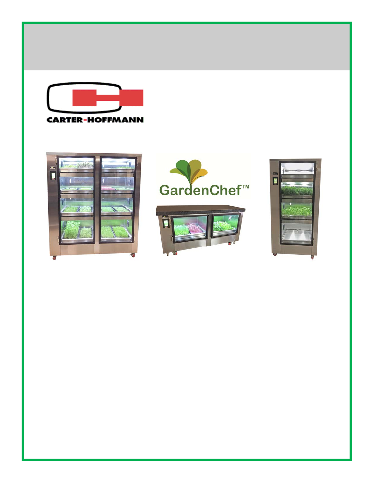
GARDENCHEF
HERB AND MICROGREEN GROWING CABINET
Models GC42, GC41, GC12, GC11
GC42
MANUFACTURED BY:
CARTER-HOFFMANN
1551 McCormick Avenue
Mundelein, IL 60060 U.S.A.
Phone: 847-362-5500
Fax: 847-367-8981
Email: TechnicalService@Carter-Hoffmann.com
GC12
Shown with custom
stone counter-top
Toll Free: 800-323-9793
GC41
PATENT PENDING
FEATURES AND SPECIFICATIONS 2
UNPACKING AND INSPECTION 3
SAFETY PRECAUTIONS 3-4
INSTALLATION & STARTUP 5-10
SETTING UP YOUR GROWING CYCLES 11
PROGRAMMING CYCLES 12
LET’S GROW 13
FUNCTIONS OF THE ZONE SCREEN 13
FUNCTIONS OF THE MAIN RESERVOIR SCREEN 13
PLANTING & GROWING 14
GROWING GUIDE 15
GROWING DO’S AND DON’TS 16
CLEANING AND MAINTENANCE 17-18
PERIODIC MAINTENANCE 19
REPLACING THE LIGHTS 20
SANITATION AND FOOD SAFETY 21
FREQUENTLY ASKED QUESTIONS 22
MICROGREEN PROBLEMS 23
RESOURCES 24-25
REPLACEMENT PARTS, WIRING & PLUMBING DIAGRAMS 26-27
WARRANTY STATEMENT 28
Part Number: 18400-3244 Printed in The United States of America Rev: KBA092117
TABLE OF CONTENTS
Page 2
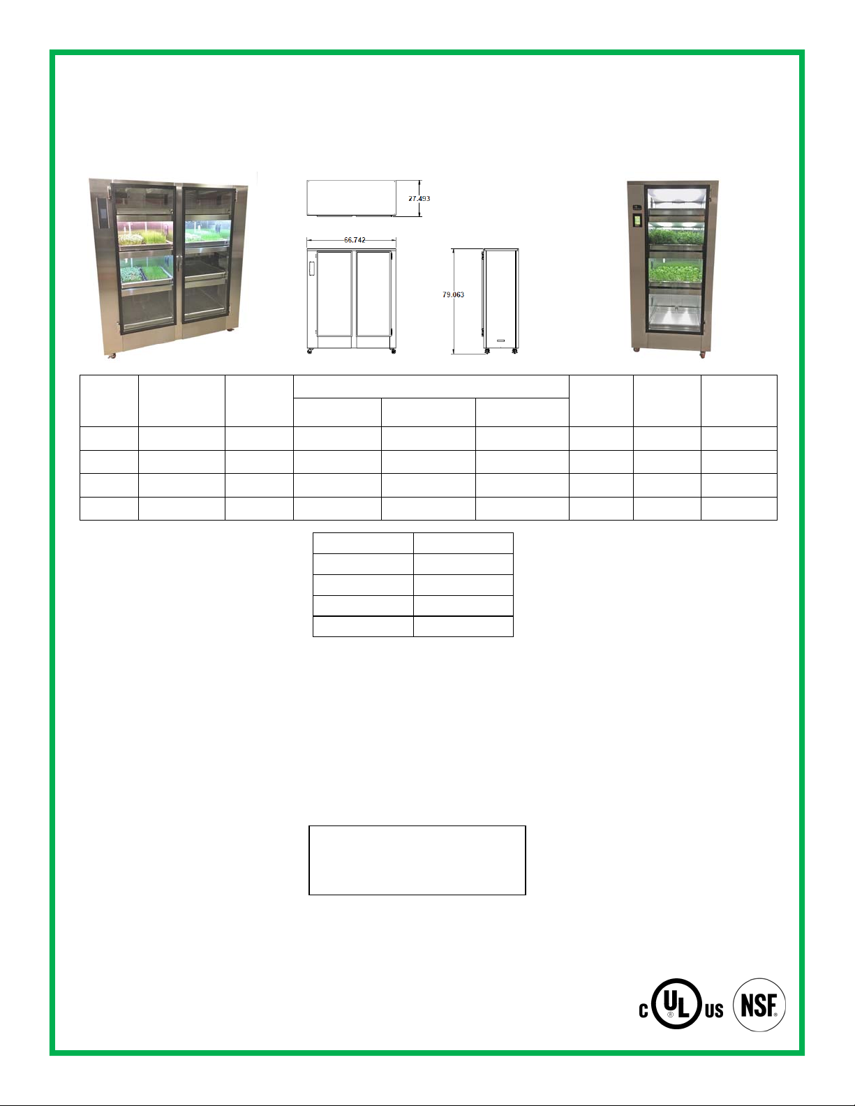
FEATURES AND SPECIFICATIONS
The GardenChef provides a self-contained environment that is ideal for growing herbs and micro greens. The lights produce the proper spectrum and an irrigation system delivers water and nutrients to the plants. The automated system provides everything the plants need to grow year round and right in the kitchen. It is preprogrammed for the growing needs
for common herbs and microgreens. You can customize the growing conditions for other plants as needed.
GC42
Model
Number
Number of
Growing
Zones
Capacity
10”x20”
Trays
Overall Dimensions Caster
Height Depth Width
GC42 8 16 79” (2007 mm) 28-1/4” (718 mm) 66-3/4 (1695 mm) 3” (76 mm) 525 (238 kg)
GC41 4 8 79” (2007 mm) 28-1/4” (718 mm) 37-1/2 (953 mm) 3” (76 mm) 275 (125 kg)
GC12 2 4 33-1/2 (851 mm) 28-1/4” (718 mm) 66-3/4 (1695 mm) 3” (76 mm) 200 (91 kg)
GC11 1 2 33-1/2 (851 mm) 28-1/4” (718 mm) 37-1/2 (953 mm) 3” (76 mm) 160 (73kg)
CONSTRUCTION...Welded & riveted
double wall, non-insulated cabinet construction.
CABINET MATERIAL... 430 series
stainless steel exterior; 301 series interior with reflective finish
BASE FRAME... 12 gauge stainless
steel full depth bolsters.
CASTERS... 3” diameter polyurethane
casters. All swivel; front casters fitted
with brakes.
LEGS…4” Adjustable legs for leveling
DOORS...Single panel tempered glass
doors set in extruded aluminum frame.
Magnetic gasket. Full length integrated
door handles.
HINGES… Adjustable edge mount hinges with chrome plate finish.
GROWING DRAWERS... Removable
growing drawers. Stainless steel construction with drainage holes in rear for
ebb and flow irrigation. Each drawer will
accommodate two standard 10” x 20”
flats with 5” or 7” greenhouse domes for
sprouting. Includes one set of growing
trays and 5” domes.
Level Growing Space
1 (top shelf) 9.875”
2 11.5”
3 13”
4 (bottom shelf) 16.75”
CONTROLS...Touchscreen digital controls. Automated system provides correct
measures of water, nutrients, relative
humidity, lighting on optimum cycle for
plant growth and nutrient data. Preprogrammed default settings for most growing needs; programmable for other growing situations. Lock-out access code.
ENVIRONMENT... Digital controls for
automatic light, watering schedule and
Default Programs:
Watering Cycle: Once every 4 days
Watering Time: 5 Minutes
Daylength: 18 Hours (lights on each day)
humidity levels for growing. Temperature
based on ambient room temperature.
WATERING SYSTEM... Automatic filtered pump/aerator irrigation system
delivers water and nutrients from the
reservoir to the plants. Programmable
watering cycle. Auto-fill reservoir. 3/8”
NPT fill connection: 3/8” NPT drain connection. pH and TDS (total dissolved
solids) sensors.
GROWING LIGHTS... Equipped with 18”
T5 high output fluorescent light fixtures.
Each fixture includes an integrated electronic ballast, 6400°K lamp with a nanotech reflector for maximum reflection.
Lights imitate the suns’ rays for optimum
growing. Removable opaque polycarbonate shields. Fully programmable light
cycles.
ELECTRICAL CHARACTERISTICS...
GC42: operates on 120 volts, 4.4 amps.
GC41: operates on 120 volts, 2.5 amps.
GC12 operates on 120 volts. 1.4 amps.
GC11 operates on 120 volts, 1.0 amps.
All are 60 cycle, single phase. Six foot
rubber cord with 3 prong grounding plug.
NEMA 5-15P.
ACCESSORIES/OPTIONS...
Starter kit: includes growing trays,
GC41
Shipping
Weight
Size
Leg
Height
4” (102 mm)
4” (102 mm)
4” (102 mm)
4” (102 mm)
mats, domes, sifter, pH & TDS calibration solutions, hydrogen peroxide, 20 gallon plastic tub, measuring
syringe
Standard 169 UL 1951
2
Page 3
UNPACKING AND INSPECTION
This appliance
should be
thoroughly
cleaned prior to use.
See the CLEANING
INSTRUCTIONS in
this manual.
NOTE: DO NOT discard
the carton or other
packing materials until
you have inspected the
appliance for hidden
damage and checked it
1. Remove the cabinet from shipping carton, ensuring that all packing materials
and protective plastic has been removed from the unit.
2. Inspect all components for completeness and condition.
3. If any freight damage is present, a freight claim must be filed immediately with
the shipping company.
4. Freight damage is not covered under warranty.
5. Check to insure all components are included: cabinet, anchoring straps, instruction packet and additional accessories.
6. Read operation instructions completely.
7. Appliance should be thoroughly cleaned before use. See CLEANING INSTRUCTIONS in this manual.
for proper operation.
Refer to SHIPPING
DAMAGE CLAIM
PROCEDURE on
bottom of this page.
WARNING: Tipping hazard
Anchor straps must be used to secure unit to a wall. Unit must be
anchored, using straps along with the anchor points located in the
upper corners of the back of the unit to structural supports in the
wall behind the unit.
CAUTION: Health and safety regulations vary by jurisdiction. Prior to installation, operator must be aware and must adhere
to all local and state codes, including proper installation, plumbing and electrical h ook up, as well as any health certificates
that may be required when growing food in your establishment. Carter-Hoffmann assumes no resp onsibility for improper
installation or use of this product or failure to adhere to local regulations.
NOTE: This unit is to be installed with adequate backflow protection to comply with all applicabl e federal, state and local
codes.
FREIGHT DAMAGE PROCEDURE
NOTE: For your protection, please note that equipment in this shipment was carefully inspected and p ackage d b y skilled per-
sonnel before leaving the factory. Upon acceptance of this shipment, the transportation company assumes full responsibility
for its safe delivery.
IF SHIPMENT ARRIVES DAMAGED:
1. VISIBLE LOSS OR DAMAGE: Be certain that any visible loss or damage is noted on the freight bill or express receipt,
and that the note of loss or damage is signed by the delivery person.
2. FILE CLAIM FOR DAMAGE IMMEDIATELY: Regardless of the extent of damage. Contact your dealer immediately.
3. CONCEALED DAMAGE: If damage is unnoticed until the merchandis e is unpacked, notify the transportation company
or carrier immediately, and then file a “CONCEALED DAMAGE” claim with them. This should be done within fifteen (15)
days from the date the delivery was made to you. Be sure to retain the container for inspection.
Carter-Hoffmann cannot assume liability for damage or loss incurred in transit, freight damage is not covered under war-
ranty. We will, however, at your request, supply you with the necessary documents to support your claim.
SAFETY PRECAUTIONS
WARNING: ELECTRIC SHOCK HAZARD
WARN ING
All service requiring access to non-insulated components must be performed by qualified service
personnel. Failure to heed this warning may result in severe electric shock.
CAUTION: ELECTRIC SHOCK HAZARD
Disconnect this appliance from electrical power before performing an y maintenance or service.
3
Page 4
IMPORTANT SAFETY INSTRUCTIONS
For your safety and the proper operation of this appliance, please follow these safety guidelines. This manual should remain
with the GardenChef so that new owners and users learn about the product and relevant safety precautions. Carefully read
through this manual before installing and using the GardenChef.
This appliance is designed to be operated by adults.
The water from your GardenChef is not for drinking.
Keep your seeds, nutrients and growing mediums in a safe, dry storage area.
When using electrical appliances basic safety precautions should be followed, including the following:
1. Be familiar with the appliance use, limitations and associated restrictions. Operating instructions must be read and und erstood by all persons using or installing this appliance.
2. This appliance must be grounded. Connect only to properly grounded outlet.
3. Use this appliance only for its intended purpose as described in the manual.
mercial establishments only.
4. Cleanliness of this appliance and its accessories is essential to good sanitation.
5. DO NOT submerge this appliance in water. This appliance is not jet stream approved. DO NOT direct water jet or steam jet
at this appliance, or at any control panel or wiring. DO NOT splash or pour water on, in or over any controls, control panel
or wiring. DO NOT use corrosive chemicals or vapors in this appliance.
6. DO NOT store this appliance outdoors. DO NOT use this product near water – for example, near a kitchen sink, in a wet
basement, or near a swimming pool, and similar areas.
7. DO NOT operate this appliance if it has a damaged cord or plug, if it is not working properly, or if it has been damaged or
dropped. Do not immerse cord or plug in water, keep cord away from heated surfaces, and do not let cord hang over edge
of table or counter.
8. DO NOT cover or block any openings on the appliance.
9. Only qualified service personnel should service this appliance.
Safety Precautions During Operation
1. Contaminated items and/or garbage must not be present in the appliance.
2. Keep the door closed when not working with the GardenChef.
3. Do not remove the growing drawers when the appliance is watering. Refer to instructions for controlling the watering and
lighting schedules.
4. Do not sit or stand on the open door or growing drawers. Doing so will ruin the drawers and slides and is a tipping hazar d.
5. Unplug the power cord from the outlet and disconnect the water supply when the appliance is not in us e. The pH sensor
must be placed back into its case with storage solution when not in use.
6. Use genuine OEM parts when servicing and repairing the appliance. Any attempts to repair the GardenChef without an authorized professional can be dangerous and void your warranty.
7. Do not place anything on top of the GardenChef.
8. Take care when removing the grow drawers as they may weigh as much as 50 pounds when full y loaded with plants, soil
and water.
9. When moving your GardenChef, ensure there is no water in the reservoir. Water may cause level issues if left in the unit
while it is being moved, and slosh out of the reservoir creating a slip hazard.
This equipment is intended for use in com-
CAUTION: Purchase supplies and seeds from reputable suppliers and follo w instructions for prop er safet y and gro wing. Carter-
Hoffmann assumes no liability for conditions resulting from improper growing, maintenance and safety. Follow all safe food handling practices when growing and harvesting.
GROUNDING INSTRUCTIONS
This appliance is equipped with a cord having a grounding wire with a grounding plug which must be plugged into an outlet that is
properly installed and grounded. In the event of an electrical short circuit, grounding reduces the risk of electric shock by providing an escape wire for the electric current.
WARNING—Improper use of the grounding can result in a risk of electric shock. Consult a qualified electrician or service
agent if the grounding instructions are not completely understood, or if doubt exists as to whether the appliance is properly
grounded.
4
Page 5
INSTALLATION AND STARTUP
WARNING:
Risk of personal injury
Installation procedures must be
performed by a qualified technician with
full knowledge of all applicable electrical
and plumbing codes. Failure could
result in personal injury and property
damage.
WARNING:
Tipping hazard
Anchor straps must be used
to secure unit to a wall. Unit
must be anchored, using straps along
with the anchor points located in the
upper corners of the back of the unit to
structural supports in the wall behind the
unit.
IMPORTANT:
Power cord is 10' long
If necessary, contact a licensed electrician to install an appropriate 15 amp
electrical circuit with correct NEMA receptacle. Ensure that the plug is accessible after installation.
DO NOT use an extension cord.
CAUTION:
Electrical Shock Hazard
LOCATION
Place the cabinet on level ground so that the inside water flows evenly. Lock the
front wheel caster brakes. Adjust the leveling legs so that they are on the floor. If
your floor is not level, adjust the legs so that the unit is level. NOTE: Unit must
be level in order to function properly.
Leave at least 36 inches (914 mm) at the front of the cabinet, so there is ample
space for opening the doors and pulling the drawers out.
Allow at least a two to six inch ventilation gap between the top of the unit and the
ceiling. Allow at least 2” of space for ventilation at the rear of the cabinet.
Install the anti-tip straps, included with the cabinet. IMPORTANT: THIS PROCE-
DURE MUST BE DONE BEFORE GOING ANY FURTHER WITH INSTALLATION OR OPERATION OF THE CABINET.
INSTALLATION OF THE ANTI-TIP STRAPS
Before you operate the cabinet it must be installed, using anchors and straps, to
prevent tipping.
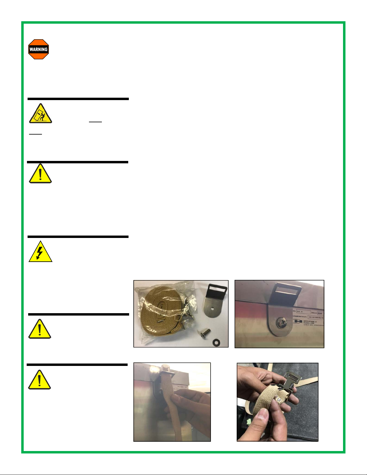
1) Verify that you have these 4 items included with your Garden Chef: (2) ¼-20 X
¾” long screw, (2) washers, (2) 8’ long straps, (4) mounting brackets. (Fig. 1)
2) Using screws, washers, and the mounting plate, mount the bracket to the back
of the cabinet as show in Figure 2
3) On the wall adjacent to the back of the cabinet, install wall anchors (acquired
by other supplier) at equal height for the type of wall being used (i.e. wood,
drywall, cement block, poured cement)
4) Install the mounting plate on the wall anchors with a screw and washer
(acquired by other supplier) matching the wall anchor.
5) Thread the loo s e end of the strap as shown in Figure 3 and then through your
wall mounted anchor
6) As shown in Figure 4, thread the loose e nd of the strap through the buckle
The ground prong of the power cord is
part of a system designed to protect you
from electric shock in the event of internal damage.
DO NOT cut off the large round ground
prong or twist a blade to fit an existing
receptacle.
IMPORTANT:
Not under warranty
Damage to unit due to being connected
to the wrong voltage or phase is NOT
covered by warranty.
IMPORTANT:
FILTERED WATER
REQUIRED
Due to varying water quality in different
municipalities, make sure that your facility water is filtered of sediment and
chemicals before hooking up the fill
lines. Sediment from hard and soft water may eventually clog up the pumps
and filters.
Figure 1
Figure 3
Figure 2
Figure 4
Continued on next page
5
Page 6
INSTALLATION AND STARTUP
WARNING:
Risk of personal injury
Installation procedures must be
performed by a qualified technician with
full knowledge of all applicable electrical
and plumbing codes. Failure could
result in personal injury and property
damage.
WARNING:
Tipping hazard
Anchor straps must be used
to secure unit to a wall. Unit
must be anchored, using straps along
with the anchor points located in the
upper corners of the back of the unit to
structural supports in the wall behind the
unit.
IMPORTANT:
Power cord is 10' long
If necessary, contact a licensed electrician to install an appropriate 15 amp
electrical circuit with correct NEMA receptacle. Ensure that the plug is accessible after installation.
DO NOT use an extension cord.
CAUTION:
Electrical Shock Hazard
The ground prong of the power cord is
part of a system designed to protect you
from electric shock in the event of internal damage.
DO NOT cut off the large round ground
prong or twist a blade to fit an existing
receptacle.
IMPORTANT:
Not under warranty
Damage to unit due to being connected
to the wrong voltage or phase is NOT
covered by warranty.
IMPORTANT:
FILTERED WATER
REQUIRED
Due to varying water quality in different
municipalities, make sure that your facility water is filtered of sediment and
chemicals before hooking up the fill
lines. Sediment from hard and soft water may eventually clog up the pumps
and filters.
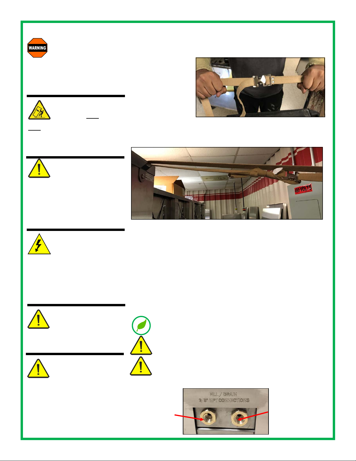
**IT IS VERY IMPORTANT THAT THIS NEXT STEP IS
COMPLETED CORRECTLY**
7. Pull both ends of the
strap as show in Figure
5, make sure that the
strap does not slide
through easily
Figure 5
8. Pull the strap tight and tie up the rest of the strap neatly as shown in Figure 6
Figure 6
Connect city water supply and city drain to the 3/8” NPT female fittings at the
back of the unit (Fig. 7). Access to the connections will be at the back of the cabinet. NOTE: This unit is to be installed with adequate backflow protection to
comply with all applicable federal, state and local codes.
City water connection must not be further than 10 feet from the cabinet and
no higher than 6 feet from the connections. A minimum of 35 PSI is required
to feed the cabinet.
Install the lights and diffuser panels (instructions on page 20)
The 120V electrical outlet sho uld b e within 6 feet of the cabinet. Do not use an
extension cord. Connect to a properly grounded outlet according the electrical
specifications for the cabinet. See page 2 for specifications.
Pipes that have not been in regular use should be cleaned an flushed with
running water prior to connecting to cabinet
Make sure the water inlet hose and drain hose are not twisted, crushed,
entangled or leaking. Do not use connection hoses that have been used
previously for other appliances.
If the unit is built in to a wall or structure, make sure that it can be easily
moved for access to the back and side panels for service and maintenance.
Fig. 7
City fill connection:
3/8” NPT female
City drain connection:
3/8” NPT female fitting
fitting
6
Page 7
START-UP
Note: the cabinet must be plugged in and plumbed by a professional technician to all applicable local and state
codes. When you plug the unit in, it will turn on and you will see the startup screen (A). The unit runs diagnostics
and start-up functions while this screen is visible. You do not need to do anything while the startup screen is showing. The unit will automatically go to th e HOME screen fol low ing the start up scree n. To unlo ck the scre en, p ress an y
button and a number pad will appear. Enter “155 1” then ““. Note: when the cabinet sits for long periods of time or
it is turned off and then on again, it will automatically revert to locked mod e. You will have to use the unlock code
any time this happens. Follow these steps to set up your GardenChef for the first time:
A
FILL THE WATER RESERVOIR USING CITY WATER
Ensure water lines are hooked up first (see page 6). Ensure the reservoir
is free of dirt and foreign objects before filling.
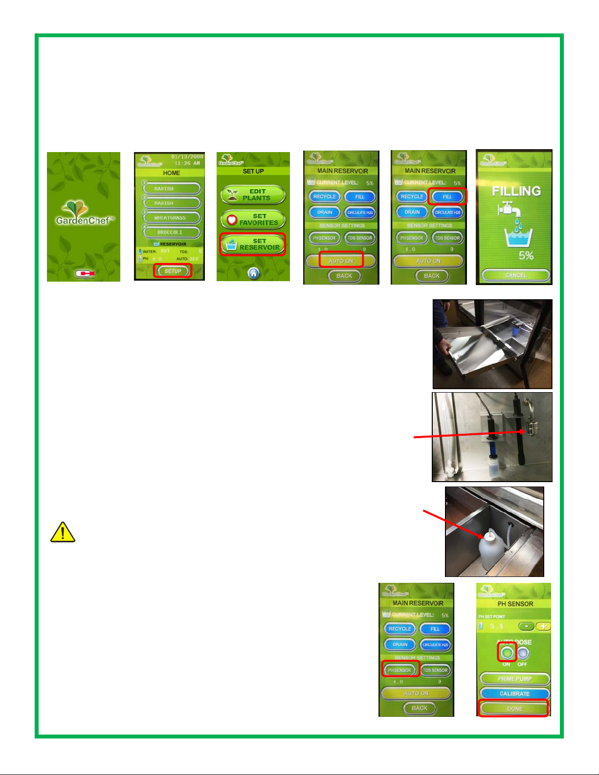
1 Remove the lower grow drawer(s) to access the water reservoir
2 From the home screen (B), press SET UP, SET RESERVOIR ( C), AUTO
ON (D) to switch to city water mode*
3 Press FILL (E) and check to make sure t he water is fillin g into the reser -
voir. The screen will display FILLING (F).
4 Once full, the GardenChef’s onboard computer will maintain a constant
water level
*For manual filling, make sure to press AUTO OFF, then fill manually to
the top of the float sensor (about 5.5” deep). Water level must be monitored and replenished if it gets low.
B
GC11: 1 zone
GC12: 2 zones
GC41: 4 zones (shown)
GC42: 8 zones
C
D
E
Fig. 1
Access the water
reservoir
Fig. 2 Float
switch/sensor; left
side of reservoir;
shuts off water
once filled to
proper level
F
SET UP THE pH DOSER (pH down solution required)
Note: Auto dosing requires that the irrigation pump be primed first.
See page 9 for instructions.
1 Remove the lower grow drawer(s) to access the dry box (Fig. 3)
2 Place a pH dosing bottle in the dry box. Any clean bottle will do as long
as it is not taller than the dry box. Drill a hole into the cap to insert the dosing line. If the cap is the same size as your pH down solution bottle, place
the cap from the dosing bottle onto the pH down bottle. If they are not the
same size, fill the pH dosing bottle with pH down solution. Place the bottle
into the dry box.
3 From the home screen (B), press SETUP, SET RESERVOIR (C), then
Press PH SENSOR (F), then
Set AUTO DOSE to ON (G) and then
Press DONE (G)
The onboard computer will check every hour and will run the dosing pump
as needed to maintain the PH level. Default PH is 5.5, but can be changed
on the SET RESERVOIR screen. Most plants need a pH level of 5 to 7.
See FAQ’s on page 16 regarding low pH.
Note: Calibration does not need to be done on initial set-up.
7
Fig. 3 Dry box
with pH dosing
bottle
F
G
Continued on next page
Page 8
CALIBRATE THE pH SENSOR
START UP(continued)
A
B
C
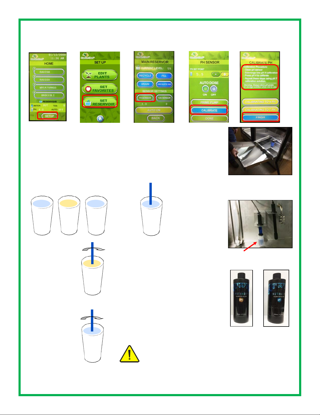
1 Remove the lower grow drawer(s) to access the reservoir (Fig.1)
2 Locate the pH sensor probe on the left side of the reservoir (Fig.2)
3 Fill one cup of water, one cup of
pH buffer #4 (Fig. 3) and one cup
of pH buffer #7 (Fig. 4)
4 Remove cap from the sen-
sor and gently wash the pH
probe in the water and dry on
a clean cloth.
D
E
Fig. 1 Access the water reservoir; the sensor will be on
the left side
water
#4
5 Gently swish
the probe in the
pH buffer #4.
Continue to swish
the probe and
follow instructions
in step 6.
7 Wash the pH
sensor in the cup
of water and dry
on a clean cloth.
Repeat steps 5
and 6 for pH buffer #7 solution
#4
#7
#7
water
6 Enter the pH calibration
screen press SETUP (A),
SET RESERVOIR (B), PH
SENSOR(C), then CALIBRATE (D) and follow the
instructions on the screen.
Calibration will take about
three minutes to complete.
8 Press DONE when calibra-
tion is complete
IMPORTANT: Safely store the pH sensor cap and use it to
stop the sensor from drying out when the water reservoir is
empty. Do not let the pH sensor dry out. Fill cap with pH #4
calibration solution before placing it on probe to store the sensor. Failure to follow this procedure will ruin the sensor and
void the warranty.
Fig. 2 Blue PH sensor
(shown with cap on)
Fig. 3
PH buffer #4
Fig. 4
PH buffer #7
Continued on next page
8
Page 9
START-UP (continued)
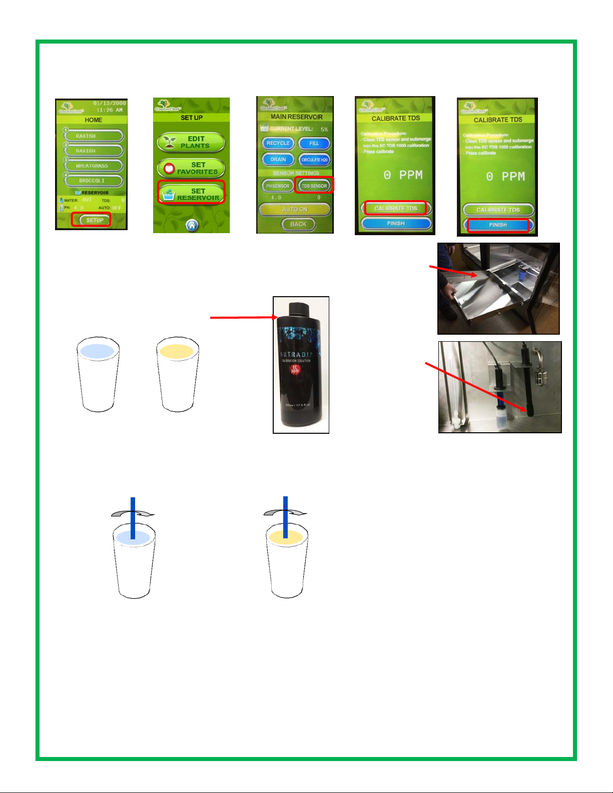
CALIBRATE THE TDS (TOTAL DISSOLVED SOLIDS) SENSOR (EC 1000 PPM solution required)
A
B
C
1 Remove the lower grow drawer(s) to access the reservoir (Fig.1)
2 Locate the TDS sensor probe on the left side of the reservoir
(Fig.2)
3 Fill one cup of water, and one
EC 1000 PPM solution
water
EC
PPM
D
Fig. 1
Access the
water reservoir
E
Fig. 2
TDS sensor
(black)
4 Gently wash the TDS probe
in the water and dry on a cloth
5 Gently swish the probe in EC
PPM solution and, while swishing
the probe, enter the calibration
screen.
water
EC
PPM
6 To enter the TDS calibration screen press SETUP (A), SET RESERVOIR
(B), TDS SENSOR(C), then CALIBRATE (D) and follow the instructions on
the screen. Continue to swish the probe in the solution for three minutes.
Calibration will take about three minutes to complete.
Press FINISH (E) when complete.
9
Page 10

PRIMING THE IRRIGATION PUMP
START-UP (continued)
Access reservoir (Fig. 1)
1 If present, remove the bottom grow trays
2 Slide out drawers to access the reservoir
Fill reservoir
1 Make sure that the unit has been connected to the water and
power according to local codes
2 From the HOME screen, press SET UP, SET RESERVOIR,
AUTO ON, FILL
3 Wait until the reservoir is full with water. Monitor the filling of
the reservoir to assure proper fill.
Fig. 3
Priming valve
in OPEN
position
Priming
1 Access the priming valve near the circulation pump. It should
be in the OPEN position and water should be flowing downwards
into the reservoir
2 From the HOME screen, select ZONE 8 if you have a GC42,
ZONE 4 if you have a GC41, ZONE 2 if you have a GC12 or
ZONE 1 if you have a GC11 (A). In each case this will be the
growing zone that is directly above the pumps. Press WATER
NOW (B).
3 Open (1/4 clockwise turn) and wait for steady stream of water
to come out of the priming valve (Fig 3); once you have a steady
stream of water, close the valve (Fig 4).
4 Water should now be flowing steadily from the irrigation nozzle
in the zone selected in step 2 (Fig. 5). Press WATER NOW (B) `
to turn off the watering cycle for that zone. Leave the priming
valve in the CLOSED position.
Your pump is now primed.
Fig. 4
Priming valve
in CLOSED
position
Fig. 1
Fig. 2
Irrigation
pump
Circulation
pump
Fig. 5 Zone irrigation
nozzle
10
Page 11

SETTING UP YOUR GROWING CYCLES
Note: the cabinet must be plugged in and plumbed by a professional technician. Follow these steps to set
up your GardenChef for the first time. Your GardenChef may have 8, 4, 2 or 1 growing zones and the
home screen will show the appropriate number of zones for the model that you have.
GC42
8 zones
SET UP THE DATE AND TIME
GC41
4 zones
GC12
2 zones
On the home screen, press the date/time in the upper right hand corner. This will take you to
the TIME AND DATE SCREEN.
Using the UP and DOWN arrows, set the date and time.
Press DONE when you are finished.
The date and time are now set so you can accurately program and monitor the growing cy cles.
SET UP YOUR SEED MENU
The cabinet comes with pre-set cycles for growing a variety of plants. It can also be programmed to set up the zones for special seeds or changing the lighting and watering cycles for
each plant. On the HOME screen, select the zone for the seed you would like to program:
GC42 (8 zones), GC41 (4 zones), GC12 (2 zones) and GC11 (1 zone). On the zone screen,
press CHANGE SEED and you will be taken to the FAVORITES screen.
An alphabetical list of preprogrammed seeds will appear. Scroll through the list to find the seed
you want, using the NEXT button to get to each screen (there are 5 screens, with a few spaces
left empty at the end for custom programming of new items). NONE is the first item and can
be used for designating shelves that might not be needed during a particular growing cycle. A
list of the preprogrammed seeds appears on page 14. Press SELECT to choose your seed.
Repeat for each of the zones you wish to use.
GC11
1 zone
11
Page 12

PROGRAMMING CYCLES
You can change the lighting and watering cycles for specific seeds, or new seeds that are not in the default programming cycles.
EDIT CYCLES
From the HOME screen, press SET UP. On the SET UP SCREEN, press EDIT PLANTS.
Select a plant and then the cycle will appear for that zone. You will see buttons for temperature, water and lights.
To change the temperature for when the fans turn on, press to increase or
decrease the temperature. You may also set the RH using the + and - buttons next to the
RH symbol. Fans will come on if the temperature and/or the RH rises above your settings.
To change the lighting cycle, press CHANGE to scroll through the lighting options. They
are OFF, 12/DAY, 16/DAY, 18/DAY, 20/DAY (12, 16, 18 & 20 are the hours the lights will
be on each day; default is 18 hours per day)
To change the watering cycle, press and use the arrows to select a watering cycle.
The choices for watering cycle are:
OFF: (no watering cycle)
1X DAY: (once each day)
2X DAY: (twice each day)
1-2 DAY: (once every other day)
1-3 DAY: (once every 3 days)
1-4 DAY: once every 4 days (default for most cycles; soil germination)
1-5 DAY: once every 5 days
Note: once or twice a day watering cycles are normally used for growing hydroponically, depending on your hydroponic growing media,
i.e. perlite, mats, etc.)
You may also change the duration of the watering cycle anywhere between 1 and 10 minutes. Press the +
and - buttons to increase or decrease the minutes. The default is 5 minutes.
Press BACK when you are finished. You can select another plant to change or press to return to the
HOME screen.
SET YOUR FAVORITE PLANTS
You can reduce the size of your plant selection list from the home screen
to just your favorites so you don’t have to scroll through the entire list of
saved plants to find your favorites and at the same time keep the programming for all of your plants, when you need them.
From the HOME screen, press SETUP, then from the SETUP screen, select SET FAVORITES. You will see the entire list of plants you have stored
in the controller. To set your favorites, press the screen to the right of the
plant names you would like to make your favorites. A little heart will appear, indicating that the plant is now a favorite. To de-select plants from
the list, press the heart button until it disappears. You can scroll through
the entire list using the NEXT button. To save your favorites, press the
HOME button
12
Page 13

LETS GROW!
TO START A GROWING CYCLE
On the HOME screen, select a seed for the zone you have just planted (Fig. 1), and you will enter the screen with
the settings for that zone (Fig. 2).
Press the START CYCLE button and a cycle will begin. Then press the HOME button
Repeat for each zone that you have planted. Different zones can be started on different days, so not all have to
be active at the same time and you can stagger growing cycles.
The circulation pump will operate at the top of every hour to circulate the water and mix nutrients. In the GC42
and GC12, it will run for 2 minutes. In the GC41 and GC11 it will run for one minute.
Fig. 1
Fig. 2
OTHER FUNCTIONS IN THE ZONE SCREEN
If you plant something different or move trays from one zone to another, you can change to the cycle for a different seed by pressing
CHANGE SEED. This will take you to your FAVORITES menu and
you can select from your favorites.
If you would like to do an unscheduled watering, you can press the
WATER NOW button and start a watering cycle. Monitor the watering cycle and press the WATER NOW button again when you
would like the watering cycle to stop.
To cancel a growing cycle, go to the ZONE screen for the particular
cycle you want the cancel. Press START CYCLE. This will cancel
the existing cycle and automatically start a new cycle. You will see
the day counter on the top right of the screen revert to DAY 00.
OTHER FUNCTIONS IN THE MAIN RESERVOIR SCREEN
From this screen, you can automatically drain and fill your cabinet using the DRAIN and FILL buttons. In addition
to the regular DRAIN and FILL functions, there is also a RECYCLE function. This function can be used when all
you want to do is exchange old water for new water in the cabinet.
CAUTION:
The cabinet MUST be hooked up to city water connection AND drain for doing any of these functions. It
is equipped with a last chance option to not do an automatic drain. This is built in to make sure you are
hooked up to municipal water and drain before you perform any a drain or recycle. The screen will ask
if you are sure before beginning the draining process. A draining screen will appear for you to monitor the progress on the draining cycle.
The cabinet will automatically circulate the water in the reservoir every hour. However, the CIRCULATE H2O
button can be used when adding nutrients. It will activate the circulation pump to stir and distribute the water in
the reservoir after adding nutrients. It will run for two minutes in the GC42 and GC12 and one minute in the
GC41 and CG11.
13
Page 14

LETS GROW!
PLANTING & GROWING
Planting and growing is easy in the GardenChef. Follow these simple instructions. See the growing guide for
specific plants on the next page.
Please refer to the Growing Guide and Growing Tips for successful growing and harvesting of specific plants.
See Sanitation and Safety Guidelines on the following pages 20-21 for safe growing and harvesting.
Materials Needed (planting using soil)*:
Potting Soil (sterile) Screen/Mat 1—20 gal plastic tub (unsifted soil); smaller tub (sifted soil)
Seeds Shaker Humidity domes
10” x 20” planting trays** Sifter Measuring cups & spoons
Misting bottle
*If you are planting hydroponically, you will need a soil-free medium such as perlite or soil free mat instead of soil
**You may also use 10” x 10” planting trays; 2 will fit in the same space as a 10” x 20”
1 PLACE SOIL INTO ONE OF THE TUBS
2 USING SIFTER, SIFT SOIL INTO THE SECOND TUB; YOU WILL NEED ABOUT ONE TO 1.5 CUPS OF
SIFTED SOIL PER TRAY TO BE PLANTED
3 ADD MORE SOIL TO THE FIRST TUB, ENOUGH TO FILL PLANTING TRAYS 1/2 TO 3/4 FULL AND
MOISTEN SOIL ENOUGH TO MAKE IT DAMP AND CRUMBLY—NOT WET AND MUDDY; STIR WHEN
ADDING WATER; DO NOT ADD WATER TO THE TUB OF SIFTED SOIL
(for measuring seed quantities)
4 INSERT MATS INTO
PLANTING TRAY(S)
7 SECURE HUMIDITY DOME.
MAKE SURE DOME VENTS
ARE CLOSED
5 PUT UNSIFTED SOIL IN
TRAY(S), FILL TO 1/2 TO 3/4
FULL, AND SMOOTH
8 PLACE TRAY(S) ON
SHELF IN GardenChef
6 MEASURE OUT
SEED QUANTITY AND
SEED EVENLY WITH
SHAKER (
Growing Guide, p. 15
see amounts in
).
SPRINKLE JUST
ENOUGH SIFTED
SOIL OVER SEEDS
TO COVER THEM.
IF THE TOP LAYER
OF SIFTED SOIL IS
DRY, MIST LIGHTLY TO MOISTEN
not soak the top layer).
(do
9 SET PROGRAM FOR
LIGHT AND WATERING
SCHEDULE ACCORDING TO THE GROWING
GUIDE
10 LEAVE DOME(S) ON
FOR AT LEAST 48 HOURS
(until seeds sprout)
11 REMOVE THE HUMIDITY
DOME(S) FOR THE REMAINDER
OF THE GROWING CYCLE
12 HARVEST!
Harvest all greens
Or thin out greens and use as they grow
14
Page 15

GROWING GUIDE
Seed Sowing Amount
seeds per
10”x20” tray
Amaranth 2 tsp 2-3 days 2 weeks 1 every 4 days 3 oz (95g)
Arugula 1 tsp 2-3 days 3 weeks 1 every 4 days 4.7 oz (145g)
Basil 1 tsp 2-3 days 4-5 weeks 1 every 5 days 7.5 oz (235g)
Beet Tops 1/2 cup 2-3 days 2 weeks 1 every 4 days 4.3 oz (135g)
Broccoli 1 tbsp. 2-3 days 1 week 1 every 4 days 8.4 oz (260g)
Buckwheat 1/2 cup 2-3 days 1 week 1 every 3 days 13.3 oz (415g)
Cabbage 1 tbsp 2-3 days 2 weeks 1 every 4 days 5.2 oz (160g)
Chervil 2 tbsp. 8-10 days 3 weeks 1 every 4 days 4.5 oz (140g)
Chives 2 tbsp. 4-7 days 2 weeks 1 every 4 days 2.6 oz (80g)
Cilantro 1/4 cup 8-10 days 3 weeks 1 every 4 days 4.3 oz (135g)
Dill 1 tbsp. 4-7 days 3 weeks 1 every 4 days 3.5 oz (110g)
Fenugreek 1/4 cup 2-3 days 2 weeks 1 every 4 days 6.4 oz (200g)
Flax 1 tbsp 2-3 days 2 weeks 1 every 4 days 2.7 oz (85g)
Kale 1 tbsp 2-3 days 2 weeks 1 every 4 days 6.4 oz (200g)
Komatsuna 2 tsp 2-3 days 2 weeks 1 every 4 days 6.4 oz (200g)
Lemon Balm 2 tsp 8-10 days 4 weeks 1 every 4 days 3 oz (95g)
Lentils 1/2 cup 2-3 days 1 week 1 every 4 days 5.7 oz (180g)
Lettuce 1 tbsp 4-7 days 3 weeks 1 every 4 days 2.1 oz (65g)
Marjoram 1 tsp 4-7 days 4 weeks 1 every 4 days 1.3 oz (40g)
Mizuna 1 tbsp 2-3 days 2 weeks 1 every 4 days 4 oz (124g)
Mustard 1 tbsp 2-3 days 2 weeks 1 every 4 days 6.4 oz (200g)
Nasturtium 1/2 cup 4-7 days 1-2 weeks 1 every 4 days 9.3 oz (290g)
Oregano 1 tsp 4-7 days 4 weeks 1 every 5 days 1 oz (32g)
Parsley 1 tbsp 4-7 days 3 weeks 1 every 4 days 5.4 oz ( 168g)
Pea, Sugar 1 cup 2-3 days 2 weeks 1 every 4 days 9.6 oz (300g)
Pea 1 cup 2-3 days 2 weeks 1 every 4 days 9.6 oz (300g)
Peppercress 1 tbsp 2 days 2 weeks 1 every 4 days 4.5 oz (140g)
Radish 2-3 tbsp. 2-3 days 1 week 1 every 4 days 10.3 oz (320g)
Sage 2 tbsp 2-3 days 2 weeks 1 every 4 days 2.7 oz (85g)
Savory 1 tbsp 2-3 days 2 weeks 1 every 5 days 1.1 oz (35g)
Shiso 2 tsp 2-3 days 2-3 weeks 1 every 4 days 4.1 oz (128g)
Sorrell 2 tsp 2-3 days 2 weeks 1 every 4 days 3 oz (92g)
Sorrell, Ruby Veined 1 tsp 4-7 days 2-3 weeks 1 every 4 days 5.3 oz (165g)
Sunflower 1 cup 2-3 days 1 week 1 every 4 days 12.2 oz (380g)
Swiss Chard 1/2 cup 4-7 days 3 weeks 1 every 4 days 4.3 oz (134g)
Thyme 2 tsp 4-7 days 4 weeks 1 every 5 days 1.6 oz (50g)
Wheatgrass 1 cup 2-3 days 1 week 1 every 4 days 8.3 oz (258g)
Dome On Time
(germination)
Grow Time
(harvest)
Watering
Schedule¹
(soil)
Harvest Yield
per Tray*
NOTE: If sowing
multiple varieties of
seeds in the same
growing zone, set
watering to once per
4 days
*Yields may vary depending on seed variety, quality and growing conditions
¹For soil-free (hydroponic) growing, change watering cycle to once or twice per day; frequency is dependent on t ype of media that is used
15
Page 16

GROWING DO’S AND DON’TS
DO MAINTAIN TEMPERATURE AND HUMIDITY
Keep the room temperature between 55°F and 90°F (13°C and 32°C), and the humidity level in the cabinet
between 30 and 60%.
DO KEEP IT CLEAN
Keep your growing environment clean. Clean the reservoir, reservoir filter and growing shelves every month
according to the cleaning instructions on pages 16-17.
DON’T OVERWATER
Overwatering, especially at the beginning of the growing cycle can bring on mold and mildew. Most watering
cycles have been pre-set for every 4 days and are usually sufficient for most plants, depending on the ambient
temperature and humidity.
DO USE HUMIDITY DOMES DURING GERMINATION
The humidity domes increase the temperature and humidity to enhance germination. Keep them on the trays
for the first 2-3 days, with the vents closed. Remove them when the seeds start to sprout.
DO USE PROPER SOIL OR MEDIA
Purchase clean potting soil, from a reputable supplier. Make sure there is a filter pad in the bottom of the tray
to keep dirt from running into the water reservoir. We have had good results with Happy Frog brand potting
soil, but there are many choices on the market. Don’t use garden soil as it can get compacted and interfere
with proper watering. If growing hydroponically, purchase mats or other hydroponic media such as perlite.
Note: depending on the media, growing results may be different than soil. You may have to experiment with
hydroponic media to determine which type works best for growing different plants. There are many resources
online describing the use, pros and cons of the different types of media that are available. For discussion on
hydroponic growing media, consult www.epicgardening.com
DON’T OVERFEED
Overfeeding can cause damage to plants. For best results follow the instructions on your nutrient bottle. Most
quick growing micro greens (one to two weeks) do not require any nutrients. Greens with a longer growing
cycle (herbs, arugula, etc) or greens that are used for multiple harvests require nutrients, and should only be
added after week one or two at the earliest.
DO KEEP pH LEVELS BETWEEN 5 AND 7
Balance your pH level at 5 in the beginning of the growing cycle for best results, as the pH is likely to increase
as the cycle goes on. The cabinet is equipped with an automatic dosing system to keep pH levels from going
too high. Be sure to check your dosing bottle regularly to make sure it doesn’t run out. Low pH is rare, but if it
occurs citric acid (organic) or potassium hydrochloride can be used to raise the level. Make sure they are
mixed according to manufacturer’s direction and used sparingly. Th ese and other hydroponic supplies can be
purchased at a local hydroponic growing store or on the internet.
DO SOW SEEDS A LITTLE ON THE HEAVY SIDE
Thin out young plants and allow others to grow and fill out.
DO USE HYDROGEN PEROXIDE
If you accidentally keep your humidity domes on too long or overwater your seeds, they may develop powdery
mildew. You can spray them with a mixture of hydrogen peroxide and water. Mix 1 tbsp. of hydrogen peroxide (17-35% food grade) in 1 quart of water. Spray only the soil, as the solution can cause plants to rot in on
themselves.
DO LOVE YOUR PLANTS!
Take time and care with your plants. Check them frequently for mold or other kinds of stress. You can see
great growth, even in one day!
16
Page 17

CLEANING AND MAINTENANCE
CLEANING THE RESERVOIR & IRRIGATION SYSTEM
1. Make sure cabinet is connected to city drain and water. If you are not hooked up to a drain and city water
you will need to manually drain and fill the cabinet; if this is the case, connect the drain fitting to a hose that
runs to a drain or sink. Do not activate the DRAIN function until you have a place to drain the water with a
hose to a sink or drain, observing all municipal codes. Used water from the GardenChef is not potable.
2. Remove the bottom drawer(s)
3. From the HOME screen, press SETUP
4. In the SETUP screen, press SET RESERVOIR
5. Press DRAIN. The next screen that appears will ask if you are sure. Double check that the cabinet is hooked
up to a drain. Otherwise it will drain onto your floor! If you are not sure, press no and double check. If you
are sure, press YES.
6. The cabinet will start to drain the reservoir. This may take up to 30 minutes. Once the reservoir has been
drained, wipe off any dirt with a clean rag.
7. Add your preferred cleaning solution (i.e. hydrogen peroxide mixture) into the reservoir. Follow the guidelines
on the label of the agent. The capacity of each model is: GC42 & GC12: 22 gallons; GC41: 11 gallons.
H
concentration should be 5 tsp per one gallon of water.
2O2
8. From the HOME screen, press SET RESERVOIR, then FILL. Filling should take approximately 30 minutes.
9. When the reservoir has refilled, from the HOME screen press, ZONE 1 and then WATER NOW so that the
cleaning solution flows through the GardenChef’s piping system to ZONE 1
10. Repeat step 10 for each zone
11. Once the zones and reservoir are cleaned, from the HOME screen, press SETUP, SET RESERVOIR, then
RECYCLE. This will drain the reservoir of the cleaning solution and then refill it with fresh water for your next
growing cycle.
3
10
4
10
5
12
6
12
7
12
9
12
17
Page 18

CLEANING AND MAINTENANCE (continued)
CLEANING THE GROWING DRAWERS Clean your grow drawers between each harvest. However,
keep a close eye on the environment and immediately clean any mold or organic matter.
reservoir and water lines (5 teaspoons per gallon of water). Read all warning labels on the hydrogen peroxide
or other cleaning products.
Do not use any chemically damaging or toxic cleaning products such as bleach. Do not use stainless
steel cleaner on the interior of the cabinet. Using chemical cleanin g products can be toxic and also
damage the stainless steel drawers and cabinet. You can use 30% hydrogen peroxide to clean the
Keep your growing environment clean.
Clean the reservoir, reservoir filter and grow drawers every month.
GENERAL STAINLESS STEEL
CLEANING
Clean the exterior of your cabinet when fingerprints and large amounts of dust appear
on the outer surfaces. Using Stainless Steel
cleaner from your local hardware store,
spray on and wipe down with a cloth going
with the grain (As seen in the pictures). DO
NOT USE STAINLESS STEEL CLEANER
IN THE RESERVOIR OR IN THE DRAWERS THEMSELVES. Stainless steel cleaner
is to only be used on the outer surfaces of
your cabinet!
CLEANING CAUTIONS
When you wipe down the reservoir, do not knock the pumps, misalign the pipes or the sensors.
Draining the reservoir sends water down and out from the drain hose. Water fro m the GardenChef is not for
drinking as biological residues may still be present and could be harmful.
Do not use steel wool pads to clean the reservoir as they will damage the steel and its rust-resistant finish.
Do not use detergents or solutions that contain chlorides, ammonias, alkalis or abrasive cleaners. Use only en-
vironmentally safe, non-toxic solutions in the manufacturers’ recommended concentration. Non-chlorine ble ach
from an environmentally-friendly company may be used in accordance with the guidelines on the packaging.
DAMAGE TO STAINESS STEEL IS PERMANENT, COSTLY TO REPAIR, AND IS NOT COVERED BY THE
WARRANTY
18
Page 19
PERIODIC MAINTENANCE PROCEDURE AND TIPS
INSIDE THE RESERVOIR
A. DRAIN, CLEAN AND FLUSH RESERVOIR
(Monthly)
SEE INSTRUCTIONS ON PAGE 18
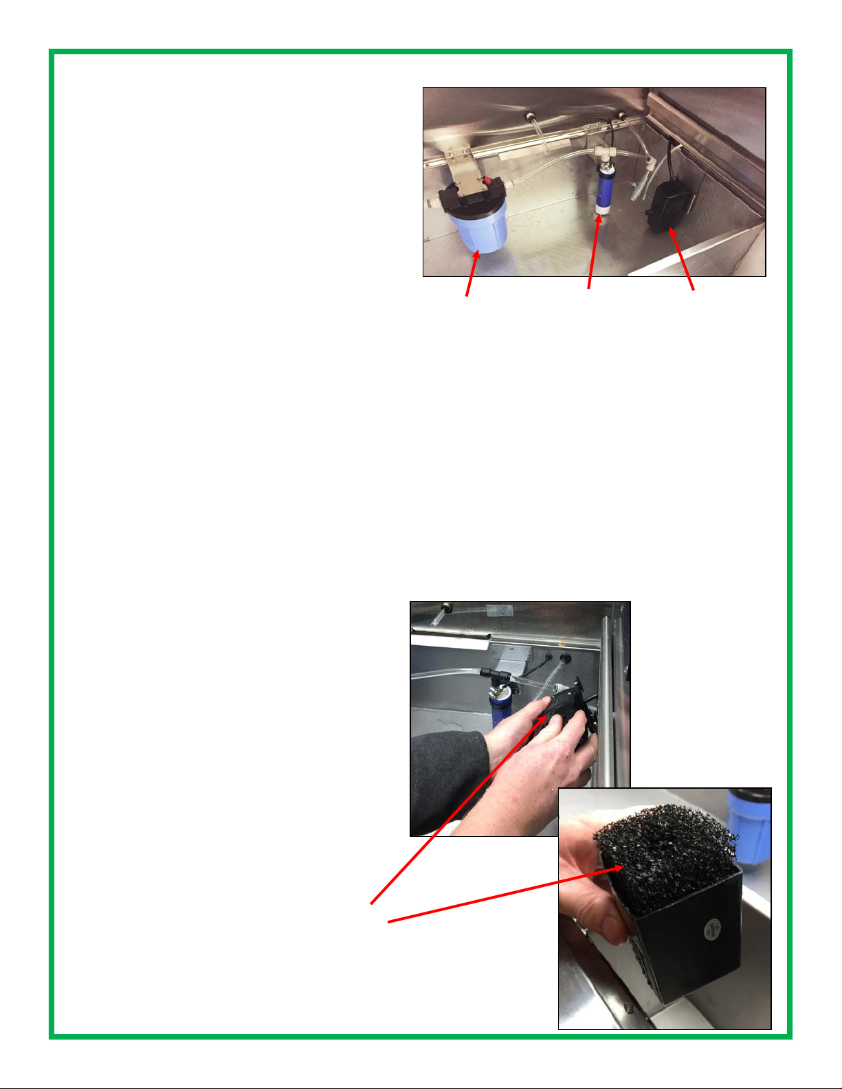
B. CHANGE FILTER (30-45 days*—more often in
areas with hard water; filter is washable for extended
use)
1. Locate the filter (large blue or white canister in
2.
3.
You may need to re-prime the pump after this process. See instructions on how to prime the pump on
page 8.
* How often you change your filter is dependent on
whether you are growing in soil or hydroponic media.
Once you get through a few growing cycles, you will
be able to determine how often it should be changed.
One indicator the filter needs to be changed is inadequate water flow to the trays during a watering cycle.
the reservoir) and unscrew the canister clockwise. A wrench for the canister was included with
your cabinet.
Remove and discard excess water.
Clean or change the filter and screw the canister
back into place.
Filter
housing
Water circulation pump;
white filter cap at bottom
INSIDE THE GROWING ZONES
A. CLEAN DRAWERS (Monthly)
1. Remove a drawer from the GardenChef
2.
Use a clean cloth with hot soapy water or hydrogen
peroxide solution to wipe down the grow drawer;
make sure the drain holes are cleared of any debris.
3.
Rinse off the drawer with clean water
4.
Dry with clean cloth
5.
Replace in cabinet
6.
Repeat steps for all drawers
Aerator/water mover
C. CHECK AND CLEAN FILTER CAP (Monthly)
1. Remove the small white cap at the bottom of the
blue pump (the pump is the smaller blue cylinder
attached to the larger filter canister).
2. Rinse the cap.
Place the cap back onto the pump
3.
* If the water flow to your growing drawers is inadequate during a watering cycle, check the filter cap to
see if it needs to be cleaned.
D. CHECK WATER MOVER /AERATOR (Monthly)
1. Locate the aerator (black pump attached with
suction cups to the right side wall of the reservoir)
2.
Check the outtake nozzle to ensure it is clear of
debris.
3.
Check the water intake tube black filter at the
end to ensure it is clear of debris. To do this,
take the cap off the bottom on the pump, check
the filter and wash out any debris that may have
accumulated. Place back in the cap and put the
cap pack onto the pump.
19
Page 20

REPLACING THE LIGHTS
Occasionally you may need to replace a light bulb.
It is a simple process, similar to changing the bulb
on a fish tank hood. For part number, see the list
on page 26.
Remove the diffuser shield by pushing it up with
both hands, then pushing it back far enough for
the front to drop down, and then pull out
Grab each end of the bulb (metal ends of tube),
rotate clockwise until you can pull the bulb out.
Insert the ends of the new bulb into the black
ends of the ballast, then turn counter-clockwise
until the bulb snaps into place.
Replace the shield by lifting it up and back over
the notch in the back of the cabinet, push up the
front until it clears the front of the diffuser frame,
pull forward and drop into place.
Push up and back
over notch in back of
cabinet, then let front
drop down
NOTE: T5 growing lights running at the
default time of 18 hours per day is consid-
ered high use and the efficiency of the
bulbs will reduce approximately 10% after 20,000
hours. Bulbs should be replaced every 18-24
months to ensure best performance.
20
Page 21

SANITATION AND FOOD SAFETY RECOMMENDATIONS
For your health and safety, please read the information below regarding sanitation, safe growing
and food safety.
Micro greens and herbs are not sprouts, but rather,
baby plants with intense flavor and nutrients. There are
differences in growing and harvesting micro greens
that make them much safer than sprouts.
Starting with Seeds
Make sure that all seeds you buy have been handled
as a food crop, not a farm crop. Seeds that have been
in contact with animals or animal waste could be contaminated with salmonella or E.coli O157 H7 and could
lead to food poisoning. Reputable seed suppliers test
all lots of seed for contamination.
Make sure that each container of seed is labeled with
the name of the seed producer or distributor, the lot
number and the country of origin.
Keep records to ensure trace-back and recall procedures.
Sanitation
Always use clean seed, as stated above, and soil, tested for E. coli and salmonella.
Sanitize equipment; regularly clean an sanitize all
growing drawers, cabinet and reservoir with hydrogen
peroxide rate recommended below. We recommend a
thorough cleaning/disinfecting weekly, or when new
trays are planted.
Don’t let greens or seeds come into contact with manure or other contaminated organic material.
Hands and equipment must be kept clean at all times
for handling micro greens. We recommend food handling gloves during planting and harvesting.
Water in the reservoir should be clean, potable water,
tested for bacterial contamination.
It is recommended that 2% chlorine from calcium hypochlorite be used as a seed sanitation method if your
intention is sprouting. This is not necessary for micro
greens, but can be done as an extra precaution.
Using Calcium Hypochlorite
Rate: 3 ounces calcium hypochlorite in 1 gallon of
warm water. Mix thoroughly and soak seed for 20
minutes. Rinse seed thoroughly in clean water, then
finish soaking time, if required, in clean water. Avoid
breathing the fumes of chlorine. Masks should be worn
to filter the fumes is you choose this method.
Using Hydrogen Peroxide:
Soak seeds in hydrogen peroxide. Add 5 ounces of 5%
hydrogen peroxide and one ounce distilled vinegar to
one quart of room temperature water. Pour the solution over the seed and let stand for 5 minutes, making
sure that all of the seed is in contact with the solution.
Drain and rinse the seeds in clean water several times
to make ensure the solution has been removed. Plant
seed as usual. This again is recommended for sprouting, but not necessary for growing micro greens and
herbs.
Growing Conditions
The environment in which E. coli and salmonella thrive
is warm and moist. Most commercial sprouts are
grown in large tanks of water, which tumble the seeds
much like a washing machine tumbles clothes. In
these conditions, if one seed is contaminated, it will be
spread to all of the sprouts in the water bath.
Micro greens are not grown in water. We recommend
growing them in sterile soil or other sterile media.
While a sprout bath spreads pathogens from one
sprout to another, soil acts like a filter, actually removing the source of contamination.
Harvesting
While a sprout is consumed whole, including the
leaves, roots and seed husk, micro greens are newly
germinated, small plants like you’d find in any garden.
All micro greens should be harvested with clean hands,
or using food handling gloves, clipped at least 2” away
from the root system and soil, using clean disinfected
scissors. Ensure all debris is removed from micro
greens and cleaned thoroughly before consumption.
Refrigerate cut micro greens. Treat them and any
foods containing them as you would any nutritious
food.
If you love sprouts, consider growing micro greens.
Their bright and intense flavor will be even more enjoyable now that you have confidence that they are also
safe to enjoy.
21
Page 22

FREQUENTLY ASKED QUESTIONS & TROUBLESHOOTING
How much soil should I put in my trays?
You should fill each tray 1/2 to 3/4 full with sterile potting soil. Make sure the soil is well moistened, but not
overly muddy or soupy. See Resources page 24 for some brands we have found to be high quality soils. For
seeds with a shorter life cycle like pea shoots, radishes, wheatgrass (1-2 weeks), 1/2 full is adequate. For
seeds with longer life cycles such as basil, oregano, arugula, etc., go with 3/4 full.
Can I mix in my seeds or cover with dirt?
For the best results for germination, sprinkle them with a fine layer of sifted soil, just enough to cover the seeds.
Usually 1 to 1-1/2 cups of sifted soil works. The finer soil spreads easily and provides a nice blanket over the
seeds for germination so that more seeds sprout and at the same rate.
When should I use plant nutrients?
The cabinet will display total dissolved solids (TDS) of the water in the reservoir. Note what the TDS is when
you first fill the reservoir and try to maintain a TDS of 100-250 above that number. Add 2.75 oz. (80ml) of nutrients at a time, wait 15 minutes to adjust the TDS.
Is the GardenChef pre-programmed?
Yes, the GardenChef is pre-programmed for the seeds listed on page 14 for soil growing. There are a few e mpty positions open in the menu for adding more seeds and you can erase and replace items in the seed menu.
You can also designate your favorite seeds for frequently used cycles. All of the seed programs are adjustable
for light and watering schedules.
How often should I perform maintenance on my GardenChef?
The cabinet requires frequent monitoring and care. It should be inspected thoroughly and cleaned at least once
a month. This may vary with your usage, depending on the number and types of plants, nutrients and TDS build
-up and growing medium (soil vs. hydroponic). Please refer to maintenance and cleaning procedures in this
manual.
Does the water reservoir keep itself filled?
Yes. If your GardenChef has been plumbed and hooked up to municipal water supply, then it is preprogrammed exchange the water in the reservoir once a week and top off as needed.
What do I do if the reservoir won’t recycle?
Check to ensure that the connection on your city drain is open and free of blockage. If the GardenChef is new,
it may not be primed. See instructions in this manual for priming the pump.
What do I do if there is a zone that won’t water?
Make sure not more than two zones are being watered at a time. Only two zones can be watered at one time,
so watering schedules for each zone will be staggered an hour apart, if they are programmed to water at the
same time. Check the programmed schedule to ensure it is not programmed to be OFF. If still no watering,
access the reservoir and insure that the pump is on and primed.
What if I see a weak/no water supply to the drawers during a watering cycle?
It’s likely that the screen over the filter is clogged with debris and needs to be cleaned or the filter needs to be
replaced. See maintenance and cleaning instructions on page 18.
What if the drawers don’t appear to be draining properly?
Check the drain holes at the back of the drawers and clear them if they are blocked. A pipe cleaner is ideal for
this maintenance.
22
Page 23

MICROGREEN PROBLEMS
WHITE MOLD
SLOW GERMINATION
CLUMPY MICROGREENS
Identification Remedy
White mold looks like a spider web crawling
across the surface of the growing media. It
starts out in one area in a small, wispy ball
and then expands quickly over the growing
media.
Make sure your trays are CLEAN be-
fore you plant
Decrease the humidity by increasing
air circulation
Decrease the seed density of your
future plantings, especially for mucilaginous seeds
Try using some grapefruit seed extract
mixed with water as an organic solution
Identification Remedy
Most micro green seeds germinate in 2-4
days, but some may take a bit longer. If
you’re seeing germination times that are longer than what is outlined in the table on page
14, something is wrong.
Increase moisture in the tray by mist-
ing or running an unscheduled watering cycle
Do a germination test on a paper towel
to see if the seed is bad. Place a
paper towel in a growing tray, moisten
it by misting with a mister and sprinkle
the seeds on top. Cover with a propagation dome and see if they sprout.
Identification Remedy
When you’re spreading your seed out in trays,
it can be difficult to get an even spread. If you
plant too densely, they will clump together,
especially if their mucilaginous. When they
sprout, a few of the seedlings will push the
rest of them up into the air, suspending the
roots and possibly bringing dirt along with
them. It makes harvesting difficult.
Decrease total seed volume planted in
each tray
Spread seeds more evenly throughout
the tray
FAILURE TO THRIVE
Identification Remedy
The greens look weak and pale. This is an all
encompassing condition that could result from
a number of factors. It is difficult to troubleshoot this condition if all of the other conditions above have been addressed.
The weakness could be due to a lack of moisture control—either too dry or too wet. In
some cases the seed is not properly planted,
or the humidity dome is removed at the wrong
time.
Make sure to read the seed growing
instructions on the packets of seeds
Stick to a normal watering schedule
Make sure you leave the humidity
domes on for an adequate amount of
time
If growing hydroponically, check your
nutrient concentration; make sure
nutrients are mixed according to the
manufacturers directions
23
Page 24

RESOURCES
The GardenChef comes with a starter set of domes and trays. An optional starter kit is available and includes growing trays, domes, mats, sifter, TDS calibration solution, PH kit, hydrogen peroxide, 20 gallon
plastic tub (for mixing/sifting soil) and measuring syringe (for adding nutrients)
Many supplies, including seeds and growing media, can be found at local greenhouses and urban garden supply sellers. The internet is a great resource for finding everything you need for your GardenChef. A list of some resources is on the next page.
Growing trays
(with drain holes)
and vented
domes
Sterile soil or
hydroponic
growing media
Seeds: purchase
from reputable
supplier
TDS reader: for
measuring the initial
TDS of your water
supply
Plastic tubs for mixing
and sifting soil
Growing mats/filters to
keep soil from running
out of the trays into
the water. Thicker
mats can be used for
hydroponic growing
Sifter to sift dry soil
to cover seeds for
germination
Plant food: for hydroponic growing or
seeds with longer
growing cycles.
Seeds with shorter
growing cycles get
enough nutrients
from the soil
Rockwool or stonewool
starter cubes/trays for hydroponic growing. Perlite
may also be used. For discussion on hydroponic
growing media, consult
www.epicgardening.com
Measuring syringe
to add nutrients
PH kit: PH#4 and PH#7
bottles to calibrate the pH
probe.
TDS 1000 EC ppm solution: To calibrate total dissolved solids probe
24
Page 25

List of brands for supplies*
RESOURCES
Growing trays
(with drain
holes) and vented domes:
Mondi™
Super Sprouter™
Sun Systems™
Sterile soil:
Fox Farms Happy Frog™
Miracle Gro™
Hydroponic growing media
(perlite, rockwool):
Handy Pantry™
Miracle Gro™
Therm-O-Rock™
Viagrow™
Plant It™
Grodan™
Growing mats/filters:
Handy Pantry™
For discussion on hydroponic
growing media, consult
www.epicgardening.com
TDS reader:
Milwaukee™
Plastic tub for mixing and sifting soil:
Rubbermaid™
pH and TDS Calibration Solutions:
Nutradip™
General Hydroponics™
Seeds:
Johnny’s Selected Seeds™
Burpee™
Cahaba Clubs Herbal Outpost™
Eden Brothers™
Plant food:
Miracle Gro™
Jungle Juice™
General Hydroponics Flora Series™
Fox Farm Gringo Rasta,™ Bush
Doctor™ and Hydroponic Trio™
* This is not a compete list or an endorsement of these products. Brands are trademarked and not affiliated with Carter-Hoffmann
25
pH down and pH up solutions:
Nutradip™
General Hydroponics™
Botanicare™
Page 26

REPLACEMENT PARTS & WIRING DIAGRAM
GARDENCHEF COMPONENTS 120V, 4.4 A
Part Number Description
18301-2649 3” swivel poly caster with brake
18309-0048 4” adjustable S.S. leveling leg
18310-0209 22” drawer slide
29038-5152 tempered glass door (GC41 & GC42)
29038-5153 tempered glass door (GC11 & GC12)
29038-3259 polymatte light diffuser panel
18616-0415 T5 growing light fixture and bulb
18614-0314 muffin fan 115V
18614-0272 fan cover
18616-0224 transformer 120/208/240, 24V40VA
18615-0172 3/8” female NPT tube fitting
18607-0017 terminal board CH03265
18602-0002 water level float switch
18605-0010 16/3 HSJO Cord w/ 5-15 plug
18614-0399 Pressure regulator
18615-0176 Straight 1/2” NPT to 3/8” tube fitting
18615-0179 Straight 1/4” NPT to 3/8” tube fitting
18615--0222 90 degree elbow 1/4” NPT to 3/8” tubing
18616-0419 TDS sensor
18616-0420 pH sensor
18616-0423 temperature/RH sensor w/housing
18614-0115 water pump 12VDC
18614-0396 recirculation pump 120VAC
18614-0397 peristaltic pump 12VDC
18614-0118 water filter housing
18614-0121 water filter cartridge 4-7/8”, 5 micons
18615-0174 replacement seal 4-3/8, 4-5/8, 5-3/8
18614-0033 solenoid valve 3/8” tube 5/16” ORF
18615-0166 3/8” bulkhead tube fitting
Part Number Description
18616-0424 power supply, 12 VDC, 120 VAC
18616-0438 Isolation board
18603-9125 remote control harness 8 pin USB
18616-0425 cable, HUBA press transmitter
18616-0418 press transmitter type 400
18615-0168 ball valve 3/8” tube
18615-0161 tee 3/8” tube
18617-0049 rubber plug grommet 9600K44
18614-0035 Solenoid valve HD 120
18614-0316 muffin fan cord, 40” #4C552
18614-0164 straight fitting 3/8” tube x 3/8” NPT
18616-0416 I/O board
18616-0417 touch screen 4.3
18615-0169 rubber hose 1/4 ID x 3/8 OD
18615-0162 90 FTG 3/8” tube
18616-0422 CAT cable
18615-0167 3/8” polyurethane tubing
18304-0033 chrome door hinge
18616-0434 EVA tubing, .188 ID x .312 OD
18616-0435 .312 OD tension spring clamp
18616-0436 nylon loop clamp 1-1/2” ID
18616-0430 propagation tray with drain holes, 10” x 20”
18616-0429 propagation 4” dome 10”x 20” w/ vents
18603-0011 pressure sensor cable
18602-0009 EMI filter
16090-4100 Starter kit for GC11
16090-4099 Starter kit for GC12
16090-4081 Starter kit for GC41
16090-4088 Starter kit for GC42
26
Page 27

PLUMBING DIAGRAM
CAUTION: Use only (OEM) original equipment manufacturer
replacement parts. Using unauthorized parts may cause
serious injury or damage to the cabinet. Replacement parts
Contact Carter-Hoffmann with your model and serial number for
replacement parts.
Call: 800-323-9793
or email:
technicalservice@carter-hoffmann.com
should be installed by a qualified service technician.
27
Page 28

WARRANTY
Carter-Hoffmann Warranty:
Carter-Hoffmann (“CARTER-HOFFMANN”) warrants to the initial purchaser of its standard Carter Line
Products that CARTER-HOFFMANN will, at its option, repair or replace, during th e warranty period set forth
below, any part of such products made necessary due to a defect in material or workmanship which is present
when the product leaves its factory and which manifests itself during the warranty period under normal use and
service.
This warranty applies only to original equipment owned and possessed by the initial purchaser and the warranty period begins on the date of original shipment from the CARTER-HOFFMANN factory and extends as follows: to component parts and labor for 12 months; to refrigeration compressor unit for one year (limited to
replacement only - not to include labor for removal, repair or replacement).
Repair or replacements under this warranty will be performed, unless otherwise authorized in writing by
CARTER-HOFFMANN, at its factory. All parts or components to be repaired or replaced under this warranty
are to be shipped prepaid to CARTER-HOFFMANN, with reimbursement credit for such part or component to
be given if found by CARTER-HOFFMANN to be defective.
CARTER-HOFFMANN neither makes nor assumes and does not authorize any other person to make or assume
any obligation or liability in connection with its products othe r than that covered in th is warranty. This warran ty applies only within the continental United States and Canada. In Alaska and Hawaii, this warra nty applies
only to and is limited to the supply of replacement parts.
Warranty Exclusions and Limitations:
Any implied warranty of merchantability or fitness for a particular purpose is hereby specifically disclaimed by
CARTER-HOFFMANN. There are no warranties, expressed or implied, which extend beyond the description on
the face hereof. This warranty does not cover and CARTER-HOFFMANN shall not under any circumstances be
liable for any incidental, consequential or other damages (such as injury to persons or property, loss of time,
inconvenience, loss of business or profits, or other matters not specifically covered) arising in connection with
the use of, inability to use, or failure of these products.
Specifications subject to change through product improvement and innovation.
Carter-Hoffmann
1551 McCormick Ave.
Mundelein, Illinois, 60060 USA
Phone: 847-362-5500 Toll free: 800-323-9793 Fax: 847-367-8981
Sales and Marketing E-mail: sales@carter-hoffmann.com
Service E-mail: technicalservice@carter-hoffmann.com
Company Website: www.carter-hoffmann.com
28
 Loading...