

Page 1
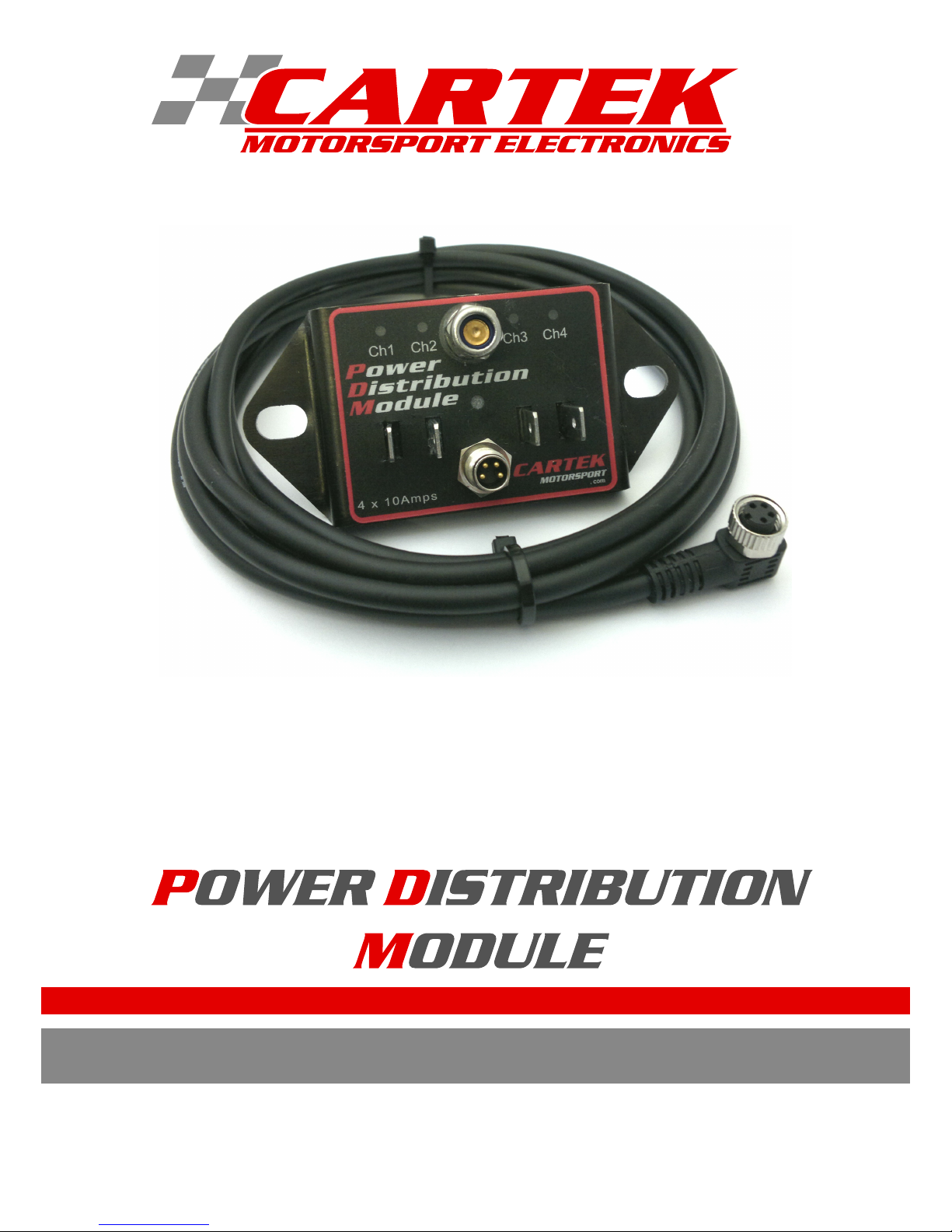
USER GUIDE AND INSTRUCTIONS JULY 2016
Page 2

CONTENTS
INTRODUCTION PAGE 1
SPECIFICATION PAGE 2
INSTALLATION PAGE 3
Unit 25, Mitchell Point
Ensign Way, Hamble
Southampton
SO31 4RF
UNITED KINGDOM
CONTACT INFORMATION
+44(0)2380 457747
www.CARTEKMOTORSPORT.com
Page 3

INTRODUCTION
INTRODUCTION
This 4 channel Power Distribution Module (PDM) from is fully electronic and designed to replace
4 relays + 4 fuses in one, small, lightweight unit. Each channel can output 10 Amps and are fully protected
against short-circuit and over current.
1
Page 4

Ch1 Ch2 Ch3 Ch4
.com
4 x 10Amps
90.0 mm
42.0 mm
10.5 mm
SPECIFICATION
2
Size: L = 90mm, W = 42mm.
Weight: 80g.
Positive Power terminal: M6 stud.
Channel Output connections 6.3mm Male Spade Terminals
Electrical Connector: Binder
Flying Lead: Binder 79 3384 42 04 (2 meter long)
Operational Voltage: 7v - 18v
Outputs:
10A - 12A (continuous), 18A (10 seconds)
each channel. Maximum total 50A.
Current consumption: 0.02A (No Load)
Operating temperature: -10°C - +85°C.
Storage temperature: -40°C - +125°C
Page 5

WARNING
3
● Please read through the Instructions thoroughly before installing on to your race car.
● The Power Distribution Module must be removed if any electric welding is being carried out on the car.
MOTORSPORT IS DANGEROUS.
THIS PRODUCT IS DESIGNED FOR MOTORSPORT USE ONLY AND SHOULD NOT
BE USED ON ROAD/STREET VEHICLES OR ON PUBLIC HIGHWAYS.
NO WARRANTY IS MADE OR IMPLIED REGARDING ANY CARTEK PRODUCTS TO
PROTECT USERS FROM INJURY OR DEATH.
USER ASSUMES ALL RISKS.
Page 6

INSTALLATION
When mounting the PDM, electrical contact must be made between the vehicle's chassis/earth and the metal
case of the PDM at its mounting points.
12v Power Input is supplied to the PDM via the M6 electrical stud. (Do not over tighten.)
Power Output connections are made using 6.3mm spade terminals.
Each channel is turned ON by connecting the corresponding channel signal wire to chassis/earth. Connection
can be made using dashboard switches, oil pressure switches, thermo-switches, etc. When a Cartek
pushbutton switch, with integrated LED, is used then the LED will display the channel status:
No LED = Channel OFF
LED on = Channel ON
Flashing = ERROR
When short-circuit or over current is detected, the PDM will shut down that channel and the corresponding
LED will begin to flash. To reset the error, switch the channel OFF then ON again.
4
Ch1 Ch2 Ch3 Ch4
.com
4 x 1 0Am ps
+12v Power Input
+
+
Channel status LEDs
No LED = OFF
Yellow = ON
Flashing Red = ERROR
Ch1 - Black wire
Ch2 - Brown wire
Ch3 - Blue wire
Ch4 - White wire
+
+
+
+
Add surge protection diode when controlling
starter solenoids.
Connect close to solenoid.
 Loading...