

Page 1
CartaSense Ltd.
Manual for the
Installation, Operation & Maintenance
Of the
Wireless Sensing Product Family
Version; 1.3 Nov. 2013
Page 2

Page 3

i
The material in this document is the proprietary of
CartaSense Ltd.
Any unauthorized reproduction, use or disclosure of this
material, or any part thereof, is strictly prohibited.
This material is meant solely for the use of CartaSense Ltd.
employees and authorized CartaSense Ltd. customers
Legal Notice
Disclaimer and Limitation of Liability
CartaSense Ltd. and its affiliates, officers, directors, employees and agents
provide the information contained in this Manual on an “as-is” basis and do
not make any express or implied warranties or representations with respect
to such information including, without limitation, warranties as to non-
infringement, reliability, fitness for a particular purpose or application,
usefulness, completeness or accuracy.
CartaSense Ltd. shall not in any circumstances be liable to any person for any
special, incidental, direct, indirect or consequential damages, including
without limitation, damages resulting from use of or reliance on information
presented herein, or loss of profits or revenues or costs of replacement
goods, even if informed in advance of the possibility of such damages.
Page 4

ii
Style Conventions
Convention
Used for
Verdana
Regular text
Arial Italics
Special terms
Monospace
Text entered by the user
Action
Notes, to draw attention and provide solutions
to specific issues.
Comments & Suggestions
Customer suggestions are important to us and enable us to
improve our documentation, making it more useful to you.
Please e-mail any comments about this guide or any other of
CartaSense documentation to:
Please include the following information with your comments:
Document title:
Page number:
Your name and organization (optional)
The following Table lists conventions that are used throughout this guide.
Contact Information
Address any technical questions or problems to CartaSense Ltd.
Address: 6 Ravnitzki St., Petach Tikva 49277, ISRAEL
Tel: +972-3-943-1543
Fax: +972-3-930-0877
Email: [email protected]
Website: www.cartasense.com
Page 5

Installation, Operation & Maintenance of the Wireless Sensing Family
iii
Term
Definition
AAA
Triple A – Battery standard size
Abbr.
Abbreviated term
AC
Alternate Current (Abbr.)
APN
Access Point Name
CS
Communication Server
DC
Direct Current
FAKRA
UHF RF Antenna connector of the USG
GPRS
General Packet Radio Service is a packet oriented mobile data service
available to all users of the 2.5G cellular communication GSM systems
GSM
Global System for Mobile communications (Cellular Standard)
LAN
Local Area Network
LED
Light Emitting Diode (Indicators of the USG and the AC adapter)
M
Million (1,000,000)
MCC
Mobile Country Code
MHz
Mega-Hertz – 1M Hertz (Hertz - radio frequency unit)
mm
Millimeters (1/1000 m)
MNC
Mobile Network Code
PASSWORD
APN's password
RF
Radio Frequency
RH
Relative humidity
RS
Resident Sensor, CartaSense resident wireless sensor
UHF
Ultra High Frequency
US
U-Sensor, CartaSense disposable wireless sensor
USERNAME
APN's username
USG
U-Sensor Gateway, CartaSense Wireless Sensor Gateway
V
Voltage
Wi-Fi
A Wireless LAN (Abbr. for Wireless Fidelity)
Terms and Definition
Captions, abbreviations and definitions used throughout this document are
presented herein.
Page 6

iv
Table of Content
Legal Notice .............................................................................................................. i
Terms and Definition .................................................................................................. iii
1 System Description ...............................................................................................1
1.1 Introduction ............................................................................................................ 1
1.2 System Overview .................................................................................................... 1
1.3 Web application ...................................................................................................... 2
2 Product description ...............................................................................................4
2.1 U-Sensors (US) ........................................................................................................ 4
2.1.1 Operating the U-Sensor ............................................................................................................. 4
2.1.1.1 Activation of the US .......................................................................................................... 5
2.1.2 U-Sensor LED Indications ........................................................................................................... 5
2.2 M-Sensor (Air) ......................................................................................................... 5
2.2.1 Deployment of the M-Sensor (Air) ............................................................................................ 6
2.2.1.1 Assembly of the M-Sensor (Air) ........................................................................................ 6
2.2.1.2 Activation of the M-Sensor (Air) ....................................................................................... 6
2.2.1.3 Operation of the M-Sensor (Air) ....................................................................................... 6
2.3 M-Sensor Soil .......................................................................................................... 7
2.3.1 Deployment of the Soil Sensor .................................................................................................. 7
2.3.1.1 Assembly of the Soil-Sensor .............................................................................................. 7
2.3.1.2 Activation of the Soil -Sensor ............................................................................................ 7
2.3.1.3 Operation of the Soil Sensor ............................................................................................. 7
2.4 M-Sensor Sun .......................................................................................................... 7
2.4.1 Deployment of the M-Sensor Sun (A-Sensor Sun) ..................................................................... 8
2.4.1.1 Assembly of the Sun-Sensor.............................................................................................. 8
2.4.1.2 Activation of the Sun -Sensor ............................................................................................ 8
2.4.1.3 Operation of the Sun Sensor ............................................................................................. 8
2.5 Resident Sensor (RS) ............................................................................................... 8
2.5.1 Deployment of the Resident Sensor .......................................................................................... 9
2.5.1.1 R-Sensor Assembly ............................................................................................................ 9
2.5.1.2 RS activation and visual indications ................................................................................ 10
2.6 U-Sensor Gateway ................................................................................................. 10
2.6.1 Deployment of the USG ........................................................................................................... 11
2.6.1.1 Assembly of the USG ....................................................................................................... 12
2.6.1.2 Activating the USG .......................................................................................................... 12
2.6.2 U-Sensor Gateway Backup power ........................................................................................... 13
2.6.3 SIM Card Requirements ........................................................................................................... 14
2.6.3.1 SIM card APN .................................................................................................................. 14
3 Installation and operation .................................................................................. 15
3.1 Pre-installation Preparations ................................................................................. 15
Page 7

Installation, Operation & Maintenance of the Wireless Sensing Family
v
3.1.1 Tools ........................................................................................................................................ 15
3.2 Site Survey ............................................................................................................ 16
3.2.1 Warehouse .............................................................................................................................. 16
3.2.2 Truck and trailer....................................................................................................................... 16
3.3 Mounting, installing and interconnecting ............................................................... 16
3.3.1 Pre-Installation Check List........................................................................................................ 16
3.3.2 Rules of “thumb” for locating wireless equipment ................................................................. 17
3.3.3 Equipment placement ............................................................................................................. 17
3.3.3.1 General Considerations for USG location ....................................................................... 17
3.3.3.2 Recommended Workmanship and Tips for Fixed USG Installation ................................ 18
3.3.3.3 Installation of Ethernet USG ........................................................................................... 18
3.3.4 U-Sensor Gateway setup ......................................................................................................... 19
3.3.5 U-Sensor Gateway activation .................................................................................................. 20
3.3.6 Resident Sensor activation ...................................................................................................... 21
3.3.7 Placement of wireless U-sensors ............................................................................................. 21
3.4 Mounting the wireless equipment ......................................................................... 22
3.4.1 U-Sensor Gateway wall Mount ................................................................................................ 22
3.4.2 Truck installation ..................................................................................................................... 24
3.4.3 R-sensor installation ................................................................................................................ 25
3.4.4 Mounting the M-Sensor: ......................................................................................................... 25
4 Web Application test utility ................................................................................ 26
5 Troubleshooting ................................................................................................. 27
5.1 Introduction .......................................................................................................... 27
5.2 Problems .............................................................................................................. 27
6 Appendices ........................................................................................................ 29
Appendix-A: Product Specifications ........................................................................... 29
A.1: U-Sensor Gateway Specifications ............................................................................... 29
A.2: Resident Sensor Specifications ................................................................................... 31
A.3: Disposable U-Sensor Specifications ............................................................................ 32
A.4: M-Sensor Specifications ............................................................................................. 34
A.5: M-Sensor Soil specification ........................................................................................ 36
A.6: M-Sensor (A-Sensor Sun) specification ....................................................................... 37
Appendix-B: Ethernet USG installation and setup process .......................................... 38
B.1: Installation assumptions ............................................................................................ 38
B.2: Tools ......................................................................................................................... 38
B.3: Starting the installation.............................................................................................. 38
B.4: Trouble shooting........................................................................................................ 39
B.4.1: Check connectivity with the USG ................................................................................................ 39
B.4.2: Network connectivity ................................................................................................................. 40
B.4.3: DHCP ........................................................................................................................................... 40
Page 8

vi
B.4.4: Static configuration ..................................................................................................................... 42
B.4.5: Check connectivity with lancusrouter ........................................................................................ 43
Appendix-C: Creating Log Files ................................................................................... 44
Appendix-D: FAQ ....................................................................................................... 50
Appendix-E: Regulatory notices ................................................................................. 53
Table of Figures
Figure 1: Typical system architecture ...................................................... 2
Figure 2: U sensor ................................................................................ 4
Figure 3: M-Sensor, Air – front & rear view .............................................. 6
Figure 5: A-sensor soil ........................................................................... 7
Figure 6: M-Sensor Sun ......................................................................... 8
Figure 7: Resident Sensor top & side view ................................................ 9
Figure 8: Resident Sensor - bottom view ................................................. 9
Figure 9: Ethernet U-Sensor Gateway .....................................................11
Figure 10: GPS- GPRS U-Sensor Gateway ...............................................11
Figure 11: Typical equipment allocation in a warehouse ............................19
Figure 12: USG mount drill scheme ........................................................22
Figure 13: Vertical USG installation ........................................................23
Figure 14: Horizontal USG installation ....................................................23
Figure 15: Resident sensor mounting .....................................................24
Figure 16: RS with USG and UHF Antenna using single mounting ..............24
Figure 17: Dashboard USG unit .............................................................25
Figure 17: M-sensor holder ...................................................................25
Figure 18: Device search status .............................................................39
Figure 19: lancusrouter configuration .....................................................40
Figure 20: Device Status .......................................................................41
Figure 21: Windows IP configuration ......................................................42
Figure 22: Terminal connection test with lancusrouter ..............................43
Figure 23: Device manager screen .........................................................45
Figure 24: USB connection ....................................................................45
Figure 25: Putty software screen ............................................................46
Figure 26: Putty software Session screen ................................................47
Figure 27: Putty software Logging screen ................................................48
Figure 28: Insert log file location ...........................................................48
Figure 29: Opening log data ..................................................................49
Figure 30: Opening log file ....................................................................49
Page 9

Installation, Operation & Maintenance of the Wireless Sensing Family
vii
List of Tables
Table 1: U-Sensor elements .................................................................... 4
Table 2: U-Sensor indicator states, after pressing the pushbutton ............... 5
Table 3: M-sensor elements .................................................................... 6
Table 4: Resident sensor elements .......................................................... 9
Table 5: RS LED indications .................................................................. 10
Table 6: USG indicators & controls ......................................................... 12
Table 7: U-Sensor Gateway LED Indications ............................................ 13
Table 8: SIM requirements for cellular USG ............................................ 14
Table 9: Pre-Installation Check List ........................................................ 16
Page 10

Page 11

System Description
Installation, Operation & Maintenance of the Wireless Sensing Family
1
1 System Description
1.1 Introduction
This manual describes the main features of the CartaSense Wireless
Sensing Product Family and defines procedures for the installation,
operation and servicing of the system products throughout sites and
locations that require environmental monitoring and control.
The CartaSense Wireless Sensing Product family consists of the following:
Single use shipment monitoring:
o U-Sensor (US)
Environmental monitoring:
o R-Sensor (RS)- Resident Sensor
o M- Sensors (MS).
U-Sensor-Gateways (USG).
Web application software management package.
The manual describes the system products and provides guidelines for a
successful system installation.
1.2 System Overview
The CartaSense Wireless Sensing Product Family includes all the elements
needed to collect measurements from sensors, transfer them to a central
server and visualize them, in a way that provides added value business
information. This business information may be used to take ad-hoc
decisions or provide the basis for business strategy, thus bringing in
significant savings.
CartaSense develops and manufactures various types of battery operated
sensors and gateways. The gateways collect measurements from all the
sensors and transfer them to a server and a web application to visualize
the measurements and generate alerts.
U-sensor (US) is a one-time-use sensor that accompanies controlled
temperature shipments.
R-sensor (RS) is a fixed installation sensor, used in warehouses.
M-sensor (MS) is a rugged sensor for outdoor use (E.g. agricultural
applications)
U-sensor Gateway (USG) wirelessly collects the measurements from
the sensors and sends it to a server.
Fixed USG – is a gateway used in warehouses or trucks, with a GPS
option.
Dashboard USG – is a mobile gateway unit, powered from the truck
cigarette lighter plug, where fixed installation in the truck is not
possible or not economical.
LAN USG – is a gateway that uses existing LAN infrastructure to
connect to the server
Page 12
Web application
2
Version; 1.3
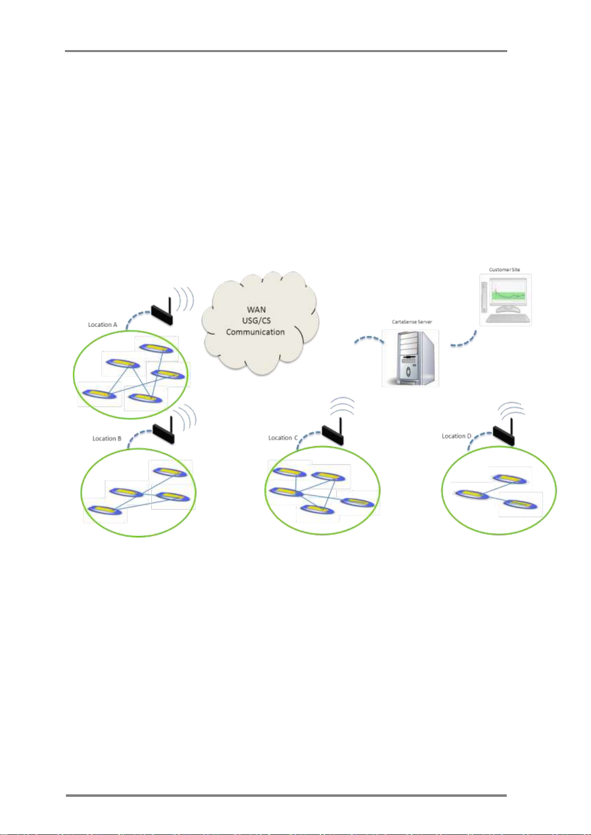
Once a USG is identified to be in communication range, data is transmitted
from the sensor to the gateway. Each USG is connected to the
Communication Server (CS) either through LAN (Ethernet gateway) or
cellular communication (GPRS Gateway), routing the received data from
all sensors..
Each one of CartaSense wireless sensors has the capability to operate as a
repeater to other Wireless sensors that are not in communication range
with the Gateway. All the sensors automatically form a dynamic, selfhealing, mesh network which is very resilient even when operating in
harsh electromagnetic environments.
1.3 Web application
A Web application provides online access to the data collected from all
around the monitored sites and faciltates real time monitoring and
observation of temperature and relative humidity conditions down to the
single package or pallet.
The application may be accessed from anywhere and enables the operator
to perform the following functions:
Figure 1: Typical system architecture
o View measurements from individual sensors or clusters of sensors.
o View status of sensors and/or USGs.
o Monitor Sensors network structure and performance.
Page 13

System Description
Installation, Operation & Maintenance of the Wireless Sensing Family
3
o Provide reports at various levels of system operation.
o Generate alarms when preset threshold conditions are exceeded.
A Web Application manual that provides a detailed description of the
application and all its features is available under separate cover.
Page 14
U-Sensors (US)
4
Version; 1.3
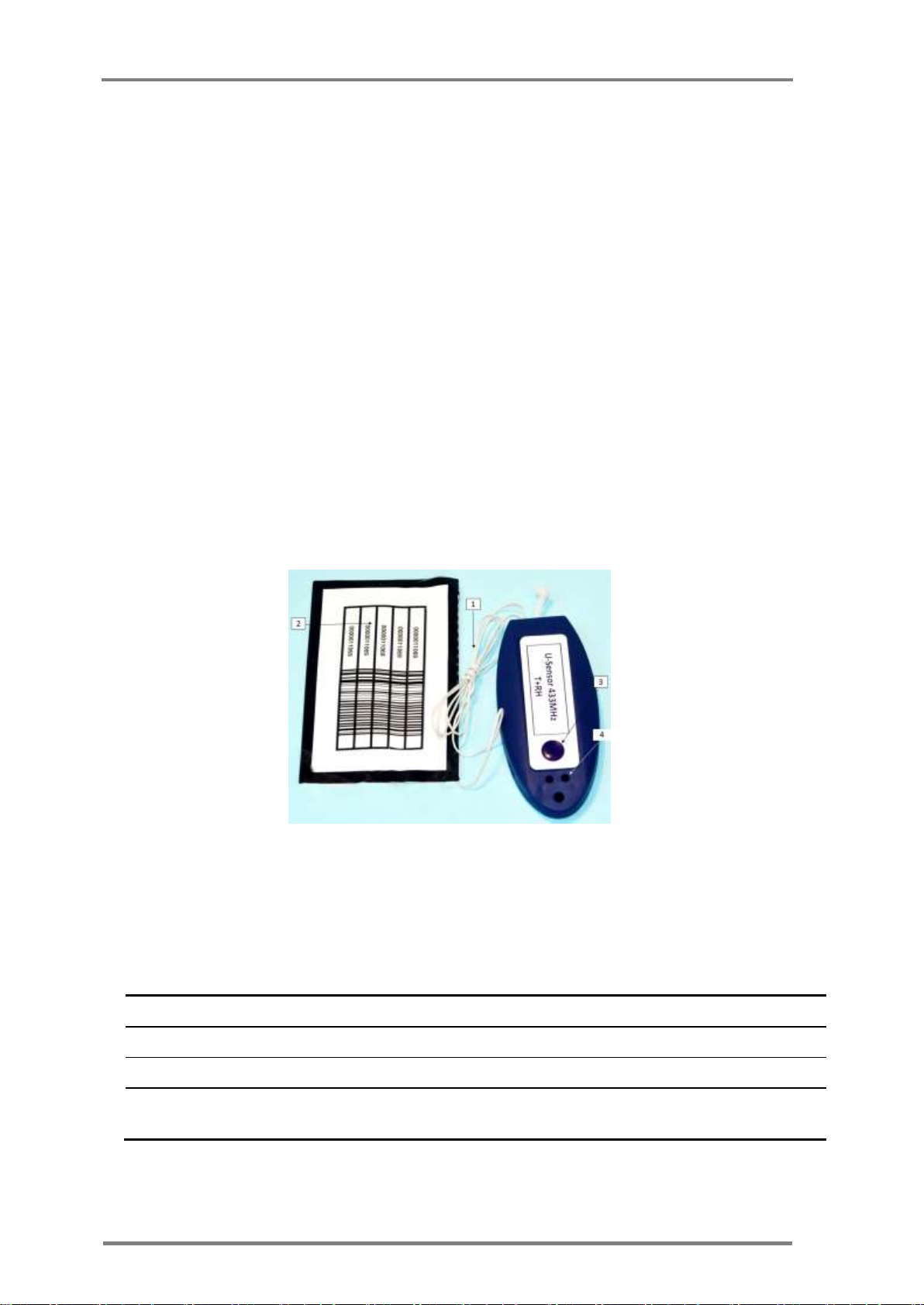
Item
Description
1
Antenna
For wireless communication
2
Barcode Sticker
U-Sensor unique identification
3
Power button
U-sensor activation and visual indication enable
4
Red LED
Active/not active, connected/not connected visual
indicator
2 Product description
2.1 U-Sensors (US)
The U-sensor (US) is a portable and disposable temperature and relative
humidity (RH) sensor.
The US is designed to be placed inside or near the monitored goods and
transmits measurements of the temperature and humidity at that location.
See Figure 2 for US unit, for detailed specification see Appendix A.3: below
The US sensor should be placed in each pallet to monitor product through the
overall supply chain.
The US periodically measures temperature and relative humidity. When
connection is available to a U-Sensor Gateway, either directly or indirectly
through another sensor, the measurements are uploaded to the
communication server. When such connection is not available, measurements
are stored in a non volatile memory and will be uploaded once wireless
connection is re-established. See 3.3.7 for setup and installation.
2.1.1 Operating the U-Sensor
Table 1: U-Sensor elements
Figure 2: U sensor
Page 15

Product description
Installation, Operation & Maintenance of the Wireless Sensing Family
5
LED Indicator
Description
1 sec single blink
Activation visual feedback. Pressing the pushbutton for three
seconds, while the US is not active, will cause the U-sensor to
go active and to make a single blink of one second
Flashing red
Network connectivity indication. Pressing the pushbutton for at
least one second, will cause the LED indicator to show the
connectivity sate of the US. A one second repetitive blink
means the US is not part of a sensor network and
measurements are logged in the sensor's memory
Constant red
Network connectivity indication. Pressing the pushbutton for at
least one second, will cause the LED indicator to show the
connectivity sate of the US. A constant on LED light means the
US is part of a sensor network and measurements are delivered
to the U-sensor gateway
Pressing the pushbutton of an active U-sensor, the red light indicator should
light up in 1 sec (either continuously or blinking). If it does not light up, the
U-sensor has not been activated
2.1.1.1 Activation of the US
The US unit is powered up by pressing the power button for 3
seconds.
2.1.2 U-Sensor LED Indications
The US contains one red LED indicator. The LED indicator is normally off in
regular operation. To make it active, and see the US state, the pushbutton
has to be pressed. There are two distinct patterns to indicate the status of
the US, as listed in Table 2.
Table 2: U-Sensor indicator states, after pressing the pushbutton
2.2 M-Sensor (Air)
M-Sensors are targeted for outdoor applications such as metering, agriculture
and for integration with external sensors. The basic unit includes internal
temperature and RH sensors and has an option for an additional module with
extended RH capabilities. See Appendix A.4: for detailed specification.
Page 16
M-Sensor (Air)
6
Version; 1.3
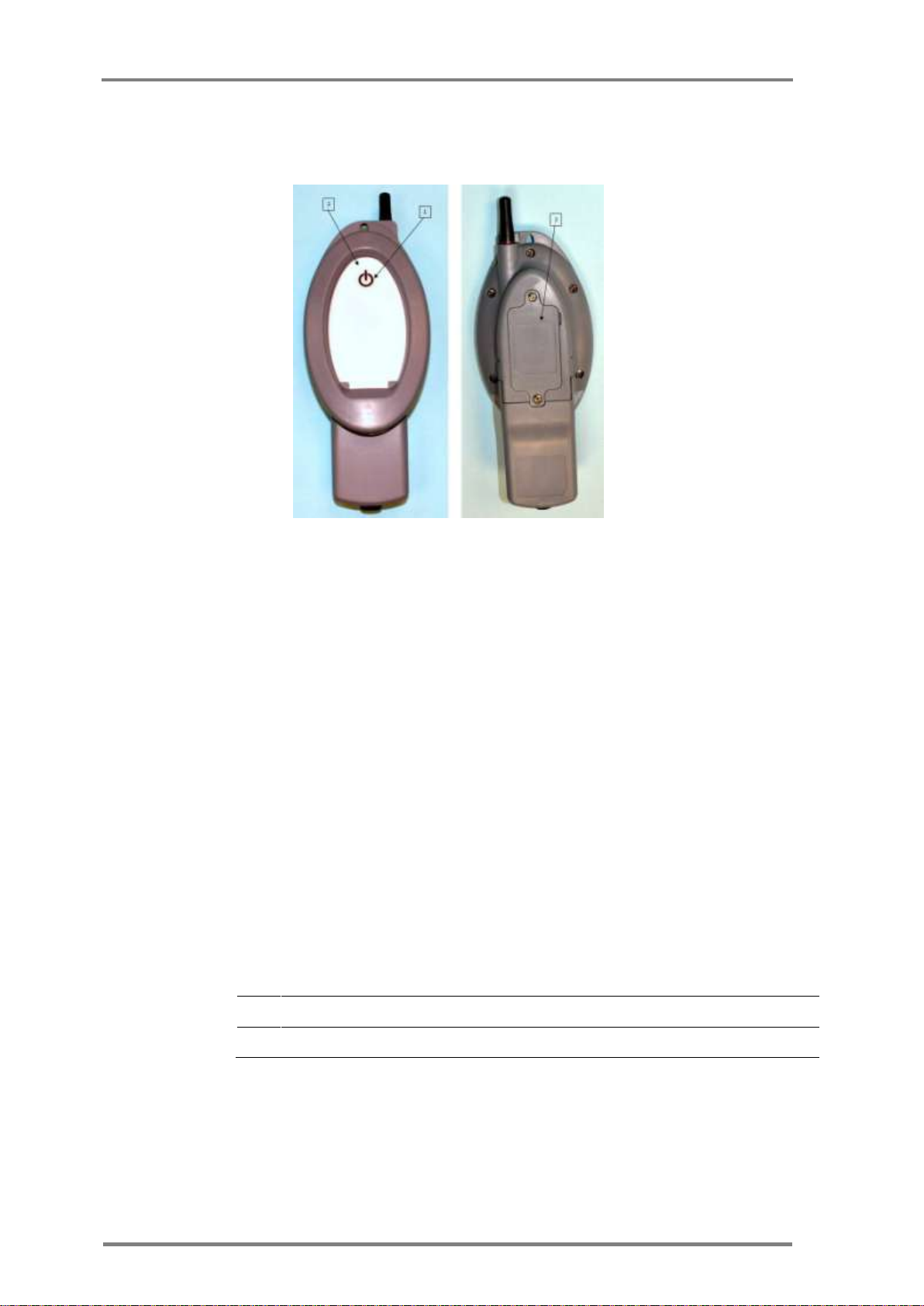
Item
Description
1
Power button
M-sensor activation and visual indication enable
2
LED indicator
Active/not active, connected/not connected visual indicator
2.2.1 Deployment of the M-Sensor (Air)
Figure 3: M-Sensor, Air – front & rear view
2.2.1.1 Assembly of the M-Sensor (Air)
Installing batteries: Unscrew the rear cover of the batteries
compartment (3) and install 2 AAA batteries. Make sure to keep
polarity of battery as indicated in the compartment.
2.2.1.2 Activation of the M-Sensor (Air)
M-Sensor is activated by a pressing the push button for 3 seconds
The M-sensor gives a positive visual indication of the success of the
activation process.
Table 3: M-sensor elements
2.2.1.3 Operation of the M-Sensor (Air)
The M-sensor, once active, connects to an available CartaSense sensors
network.
Page 17
Product description
Installation, Operation & Maintenance of the Wireless Sensing Family
7
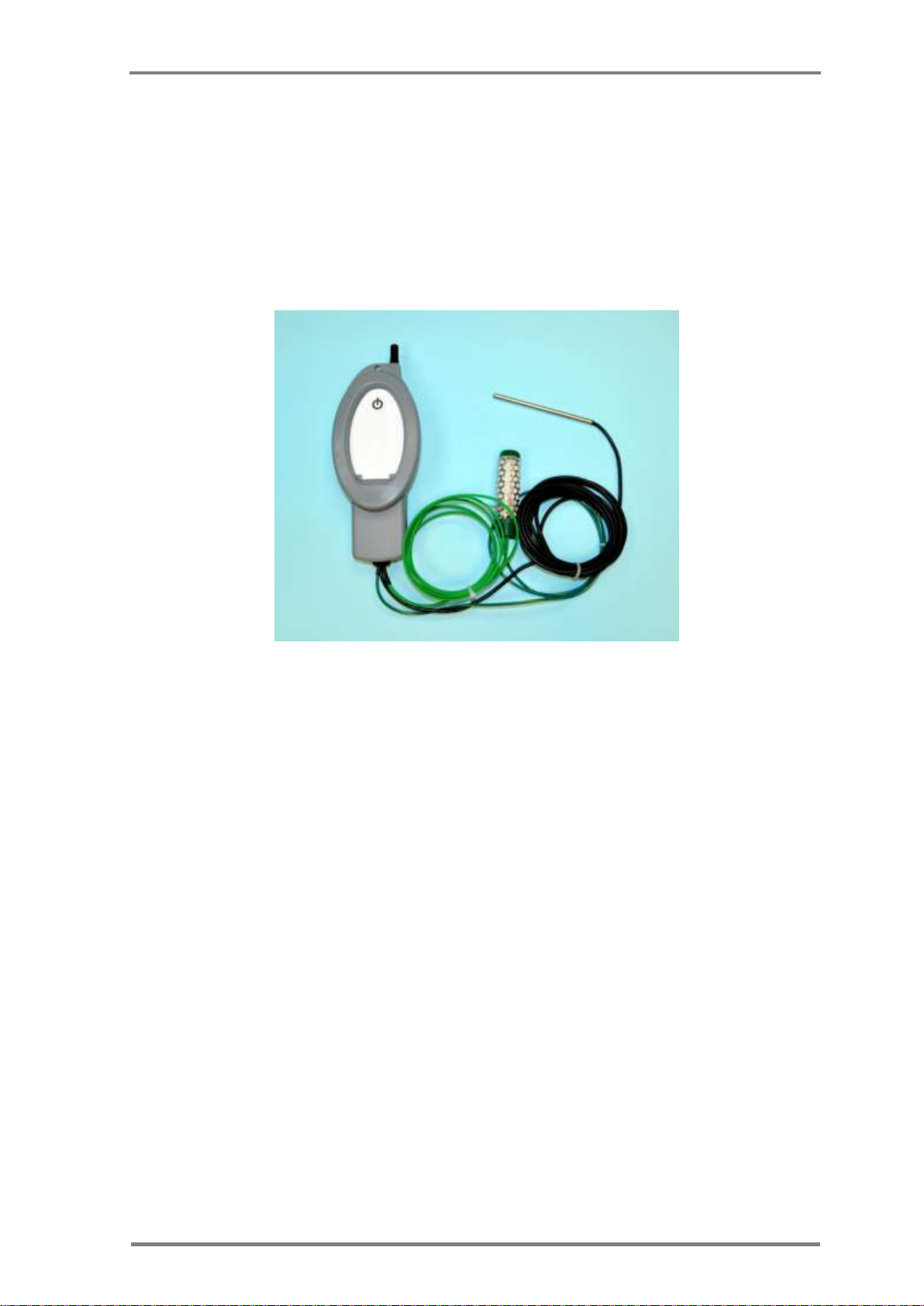
2.3 M-Sensor Soil
The soil sensor has external soil moisture sensor probe and soil temperature
probe, enabling precise monitoring of soil water content and temperature.
The M-Sensor soil is used for tracking soil moisture and temperature trends
in crops, vineyards, or other areas where moisture level is a concern.
See Appendix A.5: for detailed specification.
2.3.1 Deployment of the Soil Sensor
Figure 4: A-sensor soil
2.3.1.1 Assembly of the Soil-Sensor
Assembly of the M-Sensor soil is similar to the assembly of the M-sensor Air.
Refer to paragraph 2.2.1.1.
2.3.1.2 Activation of the Soil -Sensor
M-Sensor is activated by pressing the push button for 3 seconds
The M-sensor gives a positive visual indication of the success of the
activation process as described in Table 3
2.3.1.3 Operation of the Soil Sensor
The M-sensor, once active, connects to an available CartaSense sensors
network.
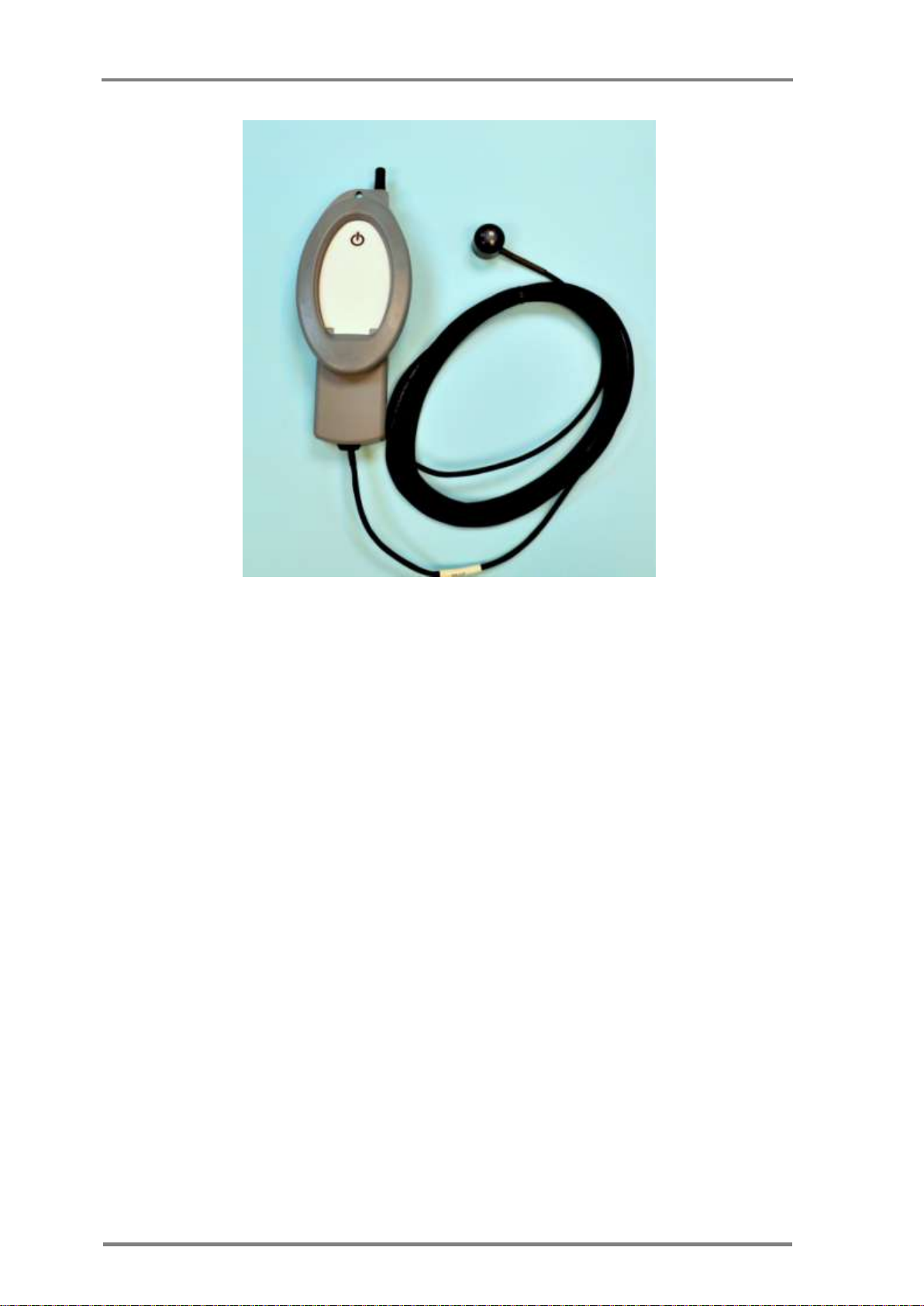
2.4 M-Sensor Sun
The Sun sensor is based on the M-Sensor and has external sun radiation PPF
sensor. The unit contains internal temperature sensors and optionally RH
sensors - see Appendix A.6: for detailed specification.
Page 18
Resident Sensor (RS)
8
Version; 1.3
Figure 5: M-Sensor Sun
2.4.1 Deployment of the M-Sensor Sun (A-Sensor Sun)
2.4.1.1 Assembly of the Sun-Sensor
Assembly is same as defined in 2.2.1.1
2.4.1.2 Activation of the Sun -Sensor
Activation is same as defined in 2.2.1.2
2.4.1.3 Operation of the Sun Sensor
The M-sensor, once active, connects to an available CartaSense sensors
network.
2.5 Resident Sensor (RS)
The RS is a stationary wireless sensor that monitors temperature and RH
environmental conditions and also serves as a range extender / repeater for
other sensors in its vicinity. See Appendix A.2: for detailed specification.
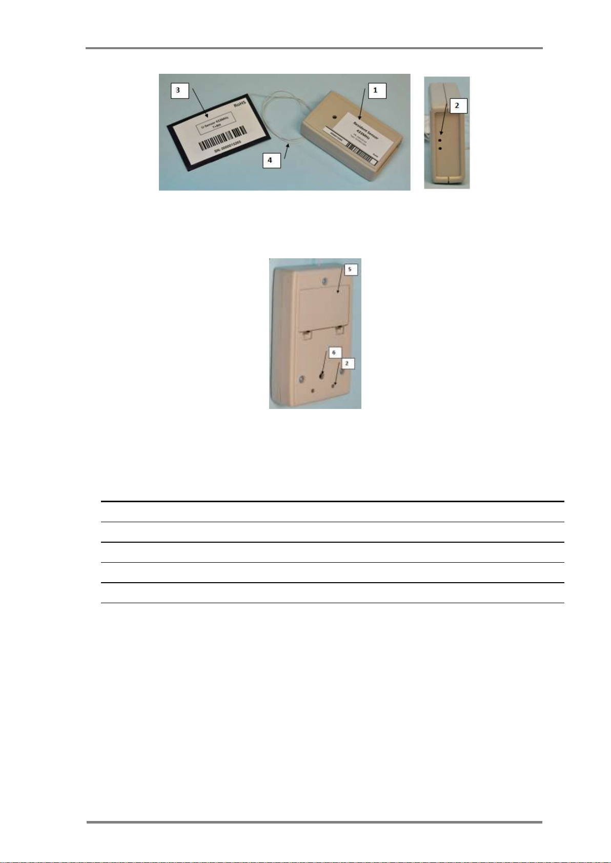
Figure 6 & Figure 7 depict the RS from top, side and bottom views and
Table 4 defined RS controls & indicators.
1
Page 19
Product description
Installation, Operation & Maintenance of the Wireless Sensing Family
9
Label
Name
Description
1
Resident Sensor ID
Unique ID of the Resident Sensor
2
Red LED Indicator
Indication for resident Sensor status
3
Sticker
Resident Sensor removable sticker
4
Antenna
Resident Sensor antenna
5
Batteries compartment
Holds 2 AAA batteries
6
Push Button
A countersunk operation button which is operated with a pin
Figure 6: Resident Sensor top & side view
Figure 7: Resident Sensor - bottom view
Table 4: Resident sensor elements
2.5.1 Deployment of the Resident Sensor
2.5.1.1 R-Sensor Assembly
Unpack the RS unit.
Open up the Batteries compartment cover (5)
Insert two AAA batteries.
Make sure to keep batteries polarity as displayed in the
compartment.
Make sure that there is good contact of both battery poles
Replace the Batteries compartment cover.
Page 20

U-Sensor Gateway
10
Version; 1.3
LED Indicator
Description
1 sec single blink
Activation visual feedback. Pressing the internal pushbutton for three
seconds (use a pin), while the R-Sensor is not active, will cause the Rsensor to go active and to display a single blink of one second
Flashing red
Network connectivity indication: Pressing the pushbutton for at least
one second, will cause the LED indicator to show the connectivity sate
of the R-Sensor. A one second repetitive blink means the R-Sensor is
NOT part of a sensor network and measurements are logged in the
sensor's memory
Constant red
Network connectivity indication: Pressing the pushbutton, for at least
one second, will cause the LED indicator to show the connectivity sate
of the R-Sensor. A constant on LED light means the R-sensor is part of
a sensor network and measurements are delivered to the U-sensor
gateway
2.5.1.2 RS activation and visual indications
Turn on the RS unit by pressing the on/off pushbutton (6) using a pin
(paper clip or similar).
The RS has one red LED indicator that can be seen from the two viewing
/ vent holes on the side and back panel (marked as element #2). This
indicator blinks as defined in Table 5:
Table 5: RS LED indications
2.6 U-Sensor Gateway
The U-Sensor Gateway is designed to transmit all the data collected by
CartaSense sensors throughout the monitored site to the communication
server and through it – to the Web application.
The USG acts as an access point for U-sensors, R-Sensors, M-sensors and
other CartaSense wireless sensors. The USG is the "root node" of the sensors
network, where all measurements are uploaded to. The USG also connects to
the communication server, further uploading measurements from the sensors
through an internet connection, whether cellular or LAN based.
Several versions of USGs are available. – The USGs differ in their system
interface and include the following:
Cellular GPRS interface.
GPRS cellular with GPS location module.
Dashboard mounted GPS/GPRS unit
Ethernet 10/100 MB interface
For detailed USG specifications – see Appendix A.1:
Page 21
Product description
Installation, Operation & Maintenance of the Wireless Sensing Family
11
2.6.1 Deployment of the USG
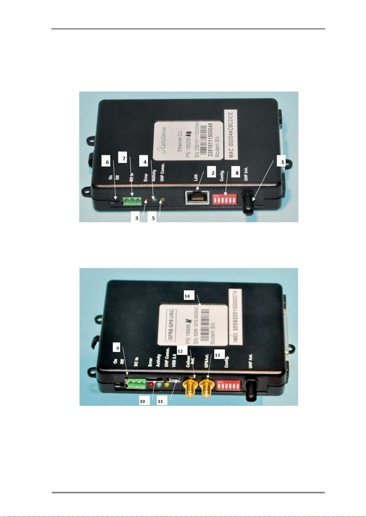
Figure 8 and Figure 9 present the Ethernet and the GPRS-GPS USG units’ and
Table 6 defines all indicators, interface connectors and controls.
Figure 8: Ethernet U-Sensor Gateway
Figure 9: GPS- GPRS U-Sensor Gateway
Page 22

U-Sensor Gateway
12
Version; 1.3
Label
Name
Description
1
UHF Antenna Connector
used for communication with CartaSense Sensors. exists in all
USG types
2
LAN Connector
Connection to LAN network
3
Red LED
Status indicator
4
Green LED
Status indicator
5
Yellow LED
Status indicator
6
On/off switch
Turn on/off the U-Sensor Gateway
7
External DC supply
Connection to 9-24V DC source
8
Configuration Switches
For proper operation – all switches should be in the OFF state
(down position- for qualified technician use)
9
SIM Card Compartment
To hold the SIM card
10
SIM Card Push Button
Pushing this button pulls out the SIM card drawer to handle the
card
11
Maintenance connector
For authorized and qualified service technicians only.
12
Cellular Antenna connector
To connect the cellular antenna for connection with the
communication server
13
GPS Antenna Connector
To connect the GPS antenna
14
U-Sensor Gateway Serial
number
Serial number of the U-Sensor Gateway
Table 6: USG indicators & controls
2.6.1.1 Assembly of the USG
Unpack the USG unit, the attached A/C adaptor
1
, and the
attached UHF and cellular antennas2.
Connect the UHF and cellular antennas.
Connect the power adaptor (7).
2.6.1.2 Activating the USG
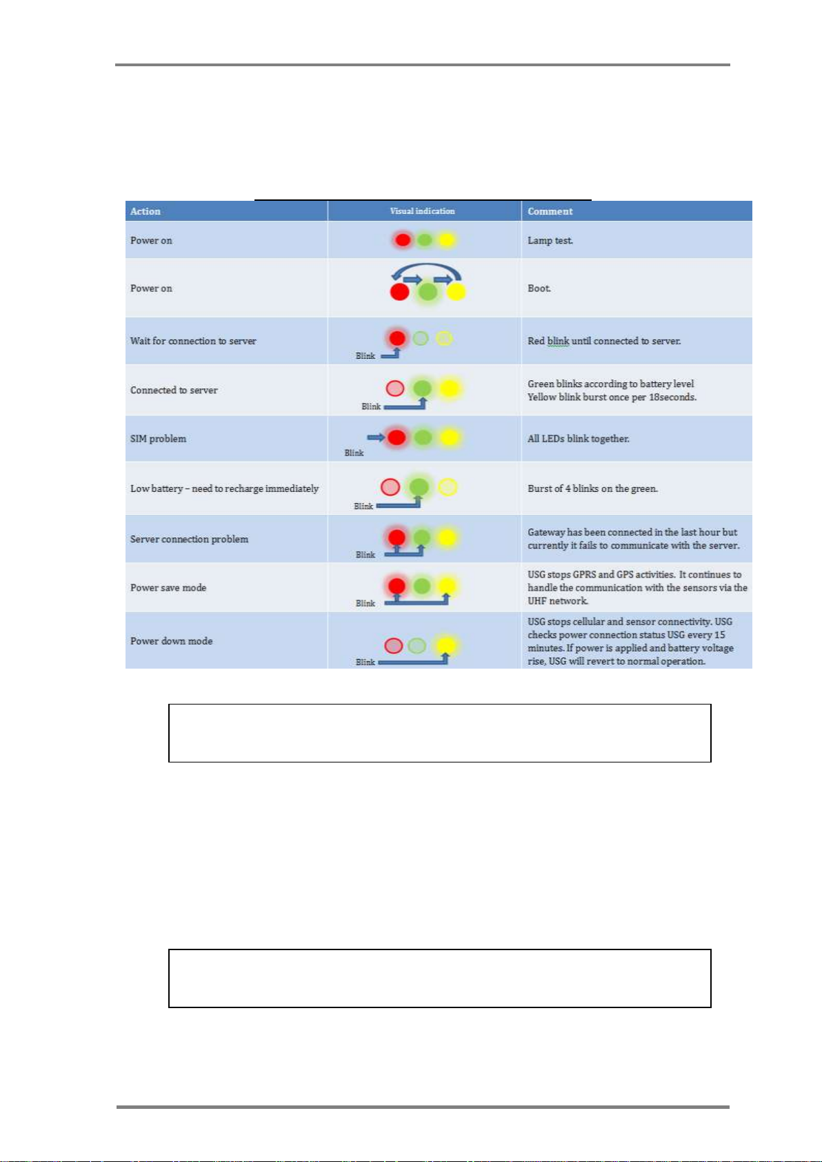
Turn on the USG, via the power switch (6). After a short "lamp test" where all
lights are on together, the LEDs will blink in a circular manner ( red green
yellow and back to red) for a period of around 30seconds.
The normal operation is that the red LED will blink until the USG connects to
the server. After connection to the server, the green LED will light, with blink
burst of the yellow LED, once per 18 seconds.
1
Power adaptor varies between stationary and truck mobile installations.
2
Type of antennas depends on USG interface, namely; Ethernet or cellular
connections.
Page 23
Product description
Installation, Operation & Maintenance of the Wireless Sensing Family
13
If SIM status is changed while the Gateway is under operation, indication will
be observed only after the gateway is restarted.
It is required to recharge the USG batteries when the YELLOW LED (5) blinks
once per second.
Observe that the Red, Green and yellow LEDs will light and blink at certain
patters – as a function of USG status. Table 7 defines the meaning of the
various LED patterns.
Table 7: U-Sensor Gateway LED Indications
2.6.2 U-Sensor Gateway Backup power
The USG includes an internal rechargeable battery.
The internal battery is used as backup power in case of short power outages.
The USG unit can operate for up to 9 hours without external power.
A built-in power save mechanism enables the USG to operate between 20-60
hours in a power saving mode, by delaying communication to the server until
the batteries have been recharged to an appropriate level.
Page 24

U-Sensor Gateway
14
Version; 1.3
#
Required SIM feature
1
GPRS support
2
Full APN (not just WAP)
3
Standard generic APN
4
SMS support
5
No voice support
6
Cancel voice mail
7
Cancel any other services
8
Send CLI (CLI revealed)
9
Open to abroad use if using a mobile gateway(Roaming)
10
NO PIN – the SIM must not be locked by PIN!
11
Provide APN username and password of the network if required
12
Mobile network Code
13
Mobile country Code
14
APN
15
USERNAME
16
PASSWORD
2.6.3 SIM Card Requirements
For a GPRS Gateway, a SIM card is required. The cellular operator that
supplies the SIM must be supported by CartaSense. Thus, first of all, one
must verify that the operator is supported by CartaSense. Verification can be
done by surfing CartaSense Demo Application, or by calling CartaSense for
verification.
In order to have an optimal cellular connection, SIM card characteristics per
Table 8 are required:
Table 8: SIM requirements for cellular USG
A SIM card should have a contract for at least 32M Byte per month depending
on implementation.
2.6.3.1 SIM card APN
SIM card APN configuration should be checked prior to the installation via the
apns.xlsx file.3 This file contains configuration of all cellular service providers
supported by the gateway. If the configuration does not match, the device
should be updated before the installation.
3
Please contact CartaSense to obtain the latest supported operators list.
Page 25

Installation and operation
Installation, Operation & Maintenance of the Wireless Sensing Family
15
3 Installation and operation
Installation of a system site consists of the following stages;
Planning – pre-installation.
Assembling and mounting of the components..
Acceptance testing of overall system.
3.1 Pre-installation Preparations
Pre-installation preparations are crucial for a successful installation of the
CartaSense system and must be performed precisely and thoroughly.
The purpose of the pre-installation preparation is:
• Identify the best location for the system components in order to
optimize the performance of the system.
• When using GPRS USG verify availability of good cellular
communication in the area of installation.
• Verify high enough locations for mounting USG units to prevent
them from being damaged by forklifts and loads.
• Locate AC outlets - Verify power outlet availability near the USG’s
planned location
• Check for the best location to place a Resident Sensor, if any. This
depends on:
- Size of area to be covered.
- Specific needs (special cooling rooms, far dockings…)
• Estimate number of RS needed.
• Check coverage
• Add RS in places with low coverage
3.1.1 Tools
The installation team should to be equipped with the following tools:
Cellular phone SIM free with WEB surfing capabilities - a cellular
phone that works with any SIM card and is capable of surfing the
internet.
Laptop with cellular internet communication.
Safe SIM – A SIM card with all the characteristics, as described in
paragraph 2.6.3 should be verified ahead of time that it is suited for
operation with the CartaSense system.
Power cord extender.
Thin screw driver – to pull the SIM card compartment out.
Mini USB connector – for debug purposes.
Page 26

Site Survey
16
Version; 1.3
Operation
All kit items are available
There is a good cellular reception on site
SIM card operates well and able to communicate
You have a site plan and you know where you want to place the equipment
You know how many Resident Sensors you have in order to boost the
Gateway
You know how many resident sensors you NEED
There is a secured location for the Gateway
There is a power outlet next to the Gateway
3.2 Site Survey
3.2.1 Warehouse
For a warehouse installation, make a floor plan of the site that includes the
following information:
Location of storage racks
walls – position and material
AC outlets
Cooling room locations
Doors, docking bays
For a GPRS USG, mark cellular reception levels
outlet (make sure the cellular phone is connected to the same operator
that supplies the SIM card to the USG).
For Ethernet USG, check for the location of RJ-45 outlets, where the
USG can be placed, make sure that the outlets are active and that there is
an adjacent AC outlet.
Take pictures of the area near each electricity outlet
Take pictures of the cooling rooms
4
in the vicinity of an AC
3.2.2 Truck and trailer.
A dashboard USG model, specifically suited for non-fixed installation in trucks
is available.
A simple experiment can verify the communication between the USG in
driver’s cabin to the sensors in the trailer.
For fixed installations in trucks and trailers, please contact CartaSense.
3.3 Mounting, installing and interconnecting
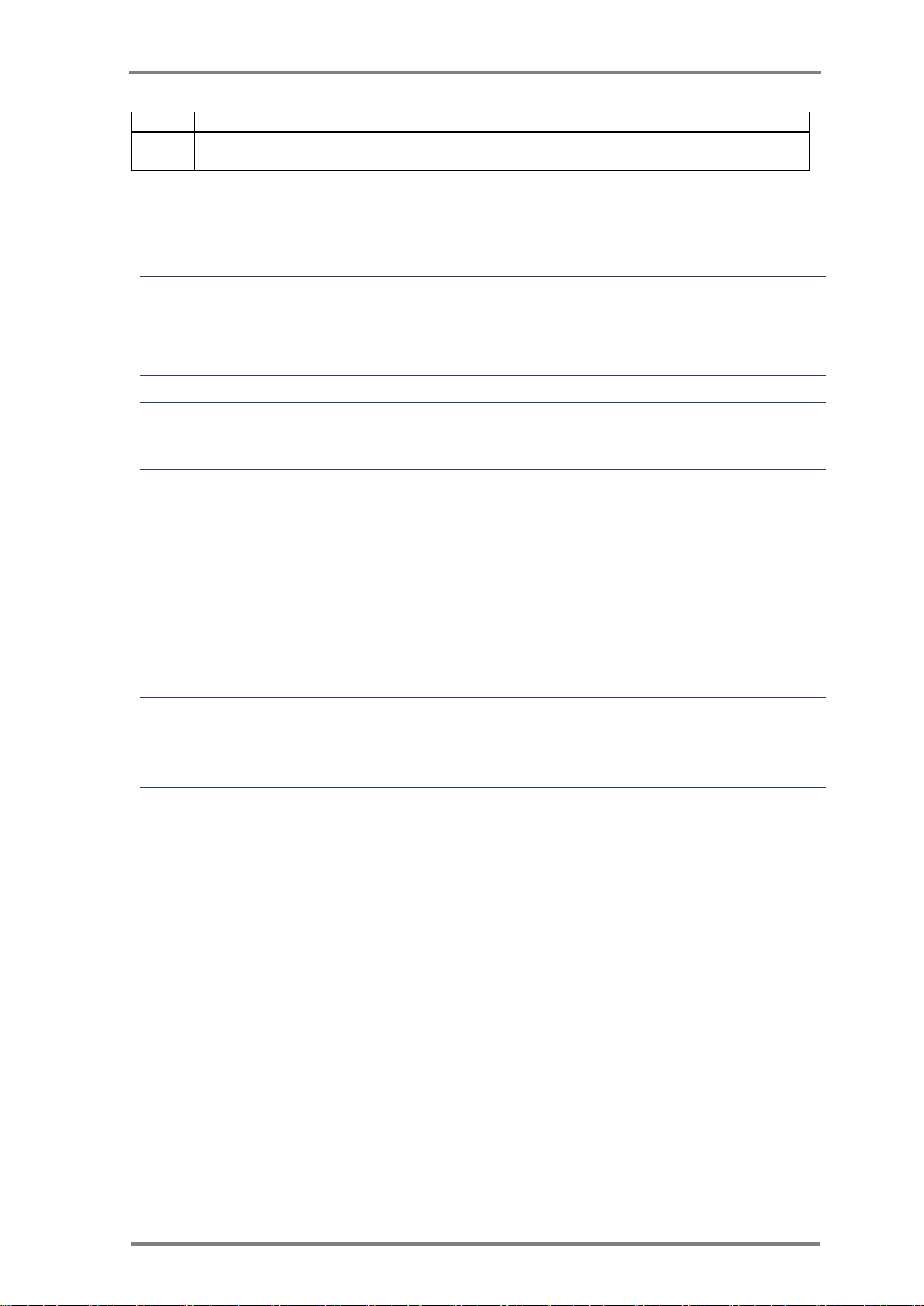
3.3.1 Pre-Installation Check List
Make sure that all steps in Error! Reference source not found. below are
erified before you proceed to the next step:
Table 9: Pre-Installation Check List
4
Levels of cellular reception may be estimated by means of the cell-phone.
Page 27
Installation and operation
Installation, Operation & Maintenance of the Wireless Sensing Family
17
Operation
If you are using an Ethernet Gateway, make sure that LAN connection is
available.
It is recommended to place the equipment in its potential location and
test it prior to mounting the units. After verification, make the necessary
location adjustments, if needed, and then mount the equipment to its
permanent place.
A Cellular antenna should be located at least 2m away from a UHF
antenna.
General
The following impair cellular reception (considered as transmission
blockers and should be avoided-if possible):
Walls: Concrete walls, Reinforced Concrete, Metal walls.
Doors: Metal doors.
Liquids: Liquid containers and boxes.
Metallic objects: Metal racks, loaded forklifts
U-Sensor Gateway: USG Must be installed in an area with the best
cellular reception (GPRS USG)
3.3.2 Rules of “thumb” for locating wireless equipment
The following issues should be considered in deciding the location of USG
units
3.3.3 Equipment placement
3.3.3.1 General Considerations for USG location
USG works as a wireless router supporting two types of wireless networks;
each one of the networks has different installation requirements:
a. Cellular communication (GPRS USG)
It is recommended to place the USG where a cellular (GSM) phone
has good reception.
The cellular antenna can be extended to a maximum of 3m from
the gateway (the maximum cable length), and should be located as
high as possible for better reception and for protection from passing
forklifts. Checking cellular reception with doors shut and open is a
good indication to the doors blocking level
b. LAN communication (Ethernet USG)
Verify that an RJ45 Ethernet outlet is available in the vicinity of the
USG.
Page 28
Mounting, installing and interconnecting
18
Version; 1.3
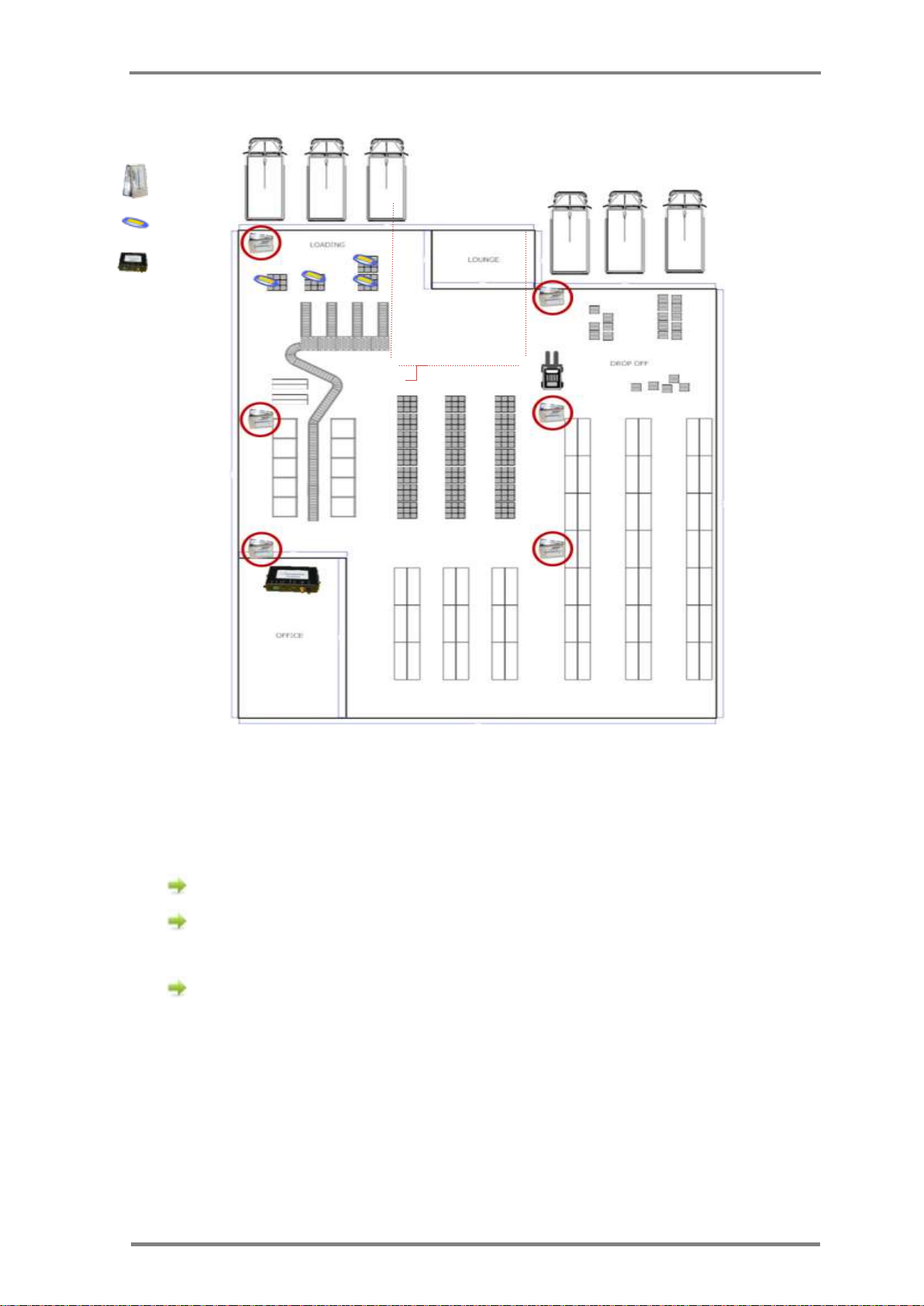
The resident sensors in this example are used to monitor the environment as well as
repeaters.
Pay attention to the clear path the resident sensors are located avoiding interference.
Lan cable length should not exceed 90 meters
5
.
3.3.3.2 Recommended Workmanship and Tips for Fixed USG Installation
IMPORTANT: the USG is NOT an outdoor unit.
USG must be kept in temperature between -20 and +60 degrees
DO NOT EXPOSE THE USG TO DIRECT SUNLIGHT.
Make sure the USG is protected from water and water spray
In case such environment cannot be met, an additional protecting case
should be employed.
CartaSense Fixed USG is usually installed in cold storage warehouses or
other facilities.
Make sure there is an electrical outlet within reach for powering the
USG.
Consider that the standard USG power cable length is 1.5m
Use an AC power extension if necessary. Properly install and fasten
the power extender. Install a dedicated power outlet if extending is
not allowed or not possible
The USG may be placed on a shelf, on a desk or mounted on the
wall.
The USG should be placed in a secure location however with an
easy access. If it is positioned in high locations, the LED indicators
should be visible.
Position properly the UHF antenna, as high as possible and as
remote as possible from a cellular antenna
The UHF antenna should preferably be located within a clear line of sight
between it and the Resident Sensors.
3.3.3.3 Installation of Ethernet USG
Appendix-B: defines procedures and solutions for the installation of the
Ethernet USG under various LAN circumstances (corporate LAN, firewalls
etc.)
Figure 10 displays typical warehouse architecture and equipment location.
5
LAN cables should be CAT5 type cables suited for telecom applications
Page 29
Installation and operation
Installation, Operation & Maintenance of the Wireless Sensing Family
19
Resident
Sensor
U- Sensor
USG
Figure 10: Typical equipment allocation in a warehouse
3.3.4 U-Sensor Gateway setup
For setup of the USG, follow the steps below (see Figure 8 and Figure 9):
All dip-switches (8) should be in “off” position (all in down position)
Connect UHF Antenna to UHF Antenna connector (1) on the front
panel
In case of a GPRS USG (either with GPS or without);
Open the SIM card compartment (9) by pushing the button
(10) using a thin screwdriver
Insert the SIM card into the compartment. The dedicated
Location fits the SIM card shape.
Push back the SIM card compartment. Make sure it is well
inserted.
Page 30
Mounting, installing and interconnecting
20
Version; 1.3
Make sure that the SIM card you are using fulfills the SIM Card Requirements.
Make sure that the SIM card you are using is supported by CartaSense
In some cases a dual antenna that supports both GPS and Cellular antenna can be used.
A Green LED on the Power Adapter indicates that it provides power feed to the USG.
Connect Magnetic cellular antenna to connector (12) on the
front panel
For GPS USGs, connect the Magnetic GPS antenna to connector (13)
on the front panel
For Ethernet USG
Connect LAN cable (RJ45) to LAN connector (2) on the front
panel
Connect the other end of the LAN cable to an available LAN.
Make sure that this LAN connection has direct access to the
internet and it is not firewalled.
For thorough technical information, refer to Appendix-B:
Plug adapter AC or DC Power Supply to PWR connector on USG front
Panel(7)
AC power supply - Plug the AC Power Supply to the electrical
outlet
DC power supply - Plug the DC Power Supply to the Cigarette
lighter outlet (for any mobile gateway such as Dashboard
Gateway).
3.3.5 U-Sensor Gateway activation
After the U-Sensor Gateway setup is completed, do the following (refer to
Figure 9 and Table 7 for USG controls):
Turn on the U-Sensor Gateway via the on/off switch (6). At first it
will undergo a sequence of LED tests and eventually will turn Red.
Page 31
Installation and operation
Installation, Operation & Maintenance of the Wireless Sensing Family
21
Assembly and operation stages are successful when power is on and a green led on the
USG starts to blink within 5 minutes from power up.
To check whether the resident Sensor is connected to a U-Sensor Gateway, push the
operation button. The red LED will blink consecutively if the sensor is connected
The U-sensor antenna should be stretched and if possible the antenna wire should
extend outside the package.
With a GPRS unit, the test sequence is prolonged–until the GPRS
modem connects.
Once the USG connects to the communication server, the Green LED
lights solid. If it blinks-it indicates that the USG battery is not fully
charged – per Table 7.
If other LED indicators are showing, refer to chapter 5 for troubleshooting
procedures.
3.3.6 Resident Sensor activation
Resident Sensors are usually deployed when:
• Stationary environmental monitoring is required.
• If the area cannot be covered with a single Gateway, then Resident
Sensors can be used as battery operated repeaters / range extenders.
To operate (turn on) the Resident Sensor See 2.5.1 and Table 5.
remove the batteries compartment cover (5)
Insert two AAA batteries.
Activate the RS by pushing the “activation PB” (6)
3.3.7 Placement of wireless U-sensors
Locating the wireless sensors in the following places will reduce the system
performance (decrease transmission range).
o Near a PC.
o Near electric motors (like industrial fans, elevators, etc.)
o Industrial frequency controllers.
o Placing the antenna directly on a metal surface.
The CartaSense Wireless Solution is optimized by placing one sensor per each
monitored pallet.
Placing the wireless sensor in the pallet is straight forward and easy:
o Power on and put the wireless sensor anywhere in or on the
pallet.
Page 32
Mounting the wireless equipment
22
Version; 1.3
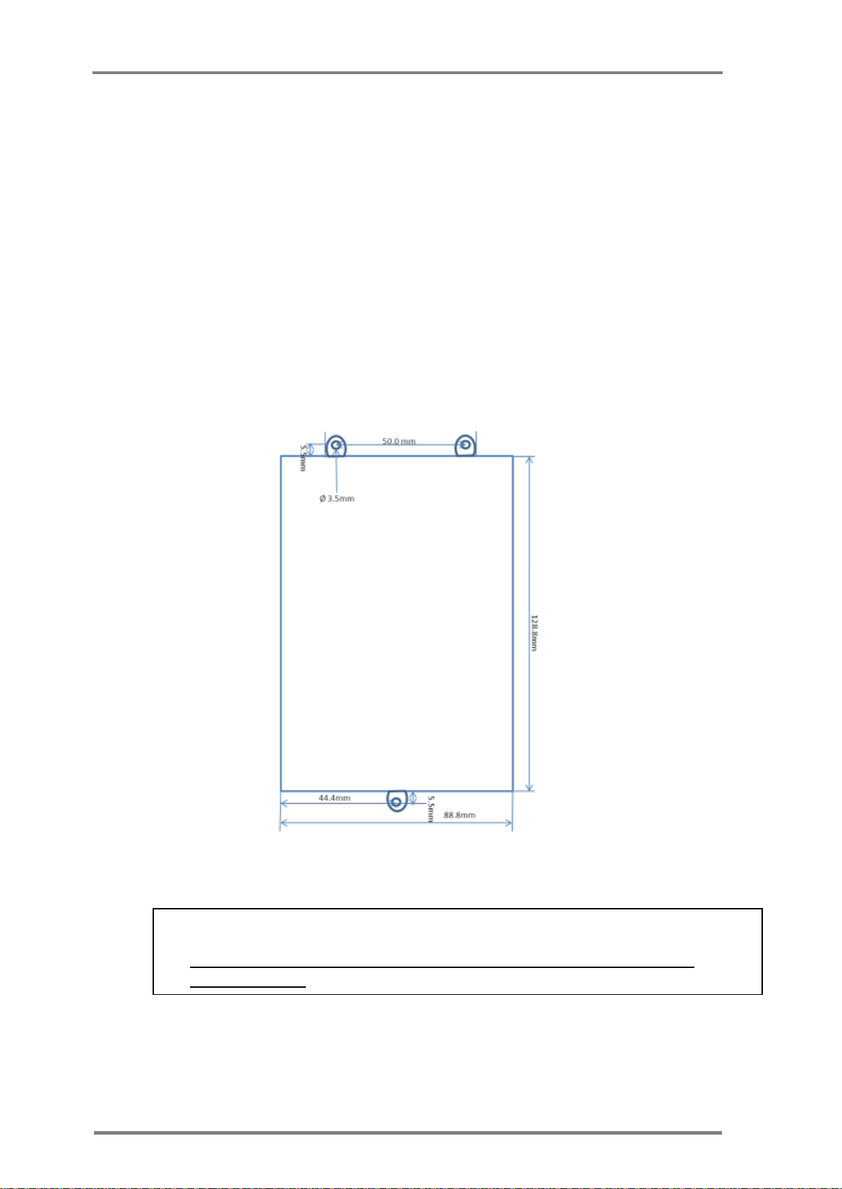
Use only flat head screws with a washer to mount the USG.
NEVER USE CONE HEAD SCREWES, AS IT WILL CAUSE DAMAGE TO THE
MOUNTNG EARS
3.4 Mounting the wireless equipment
Available option to mount the U-Sensor Gateway:
• U-Sensor Gateway wall Mount
• Truck installation
3.4.1 U-Sensor Gateway wall Mount
The U-Sensor Gateway should be affixed to its dedicated location.
Figure 11 presents the drilling layout for mounting of the USG.
Figure 11: USG mount drill scheme
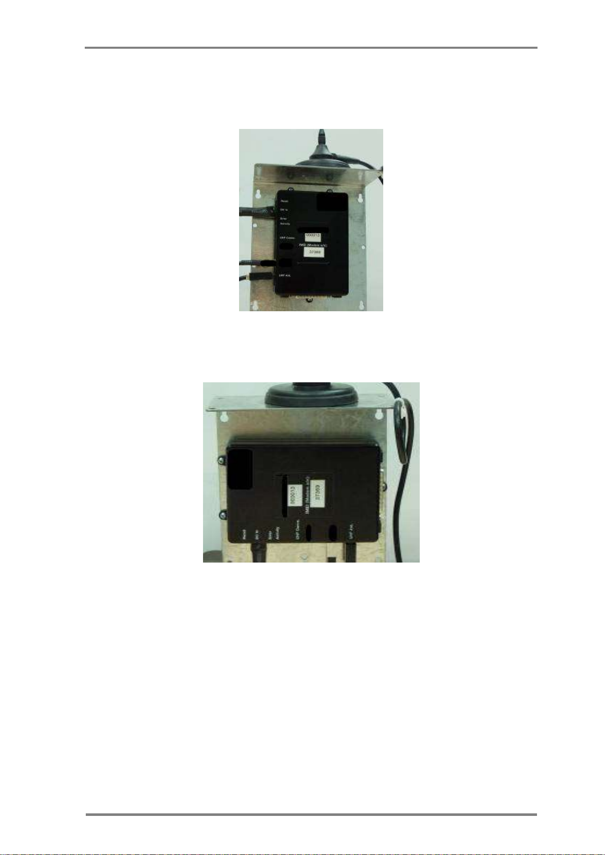
Figure 12 and Figure 13 present examples of a wall mount bracket
which can be used for:
Page 33
Installation and operation
Installation, Operation & Maintenance of the Wireless Sensing Family
23
Vertical and horizontal installation of the USG
Installation of cables
Installation of antennas
Figure 12: Vertical USG installation
Figure 13: Horizontal USG installation
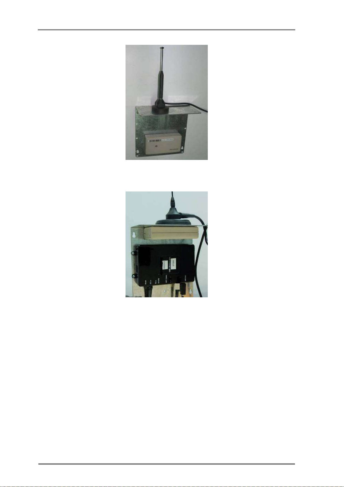
Figure 14 and Figure 15 show the USG and the RS using one mounting
bracket and also the installation of the RS separated from the USG.
Page 34
Mounting the wireless equipment
24
Version; 1.3
Figure 14: Resident sensor mounting
Figure 15: RS with USG and UHF Antenna using single mounting
3.4.2 Truck installation
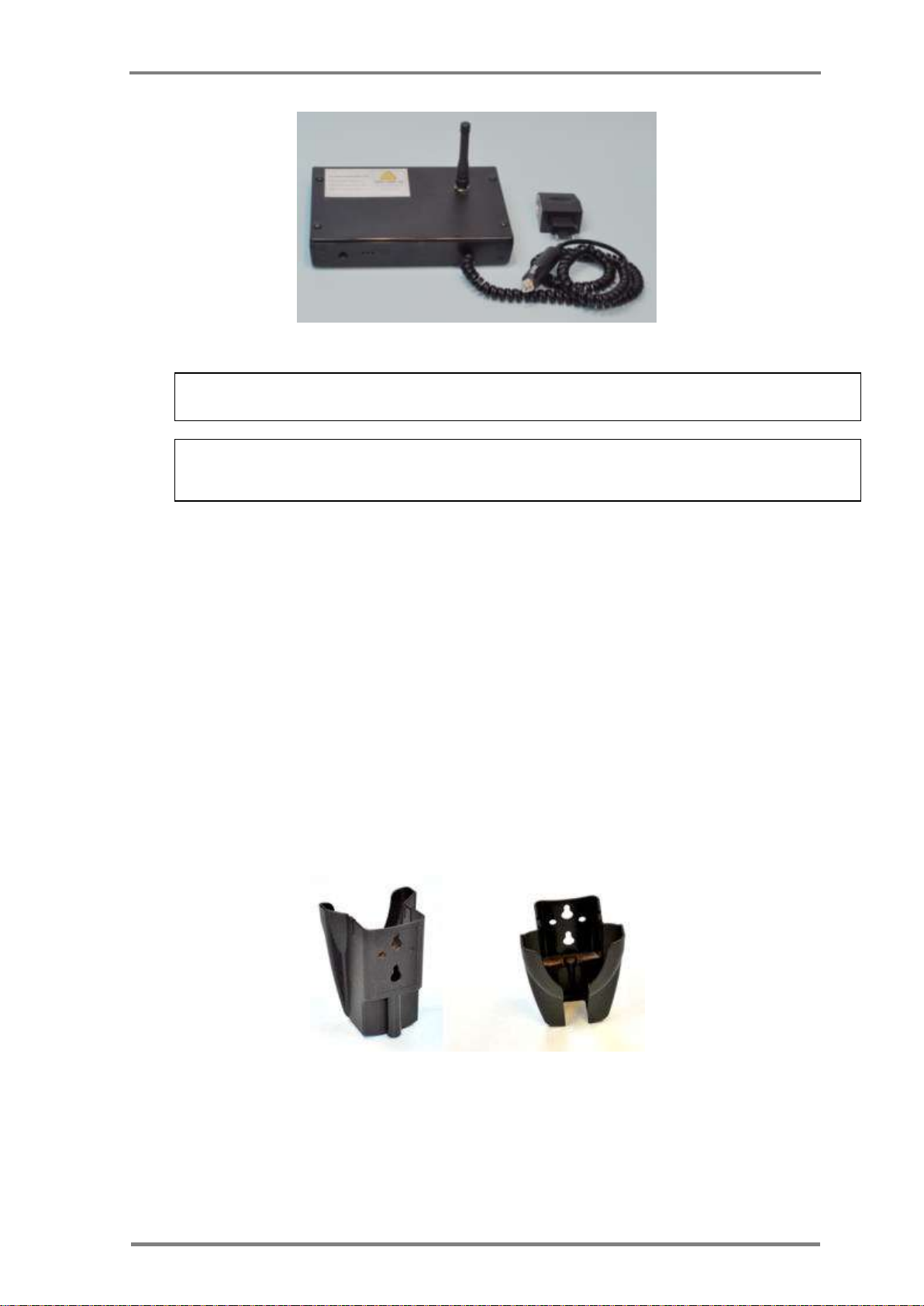
For a truck installation, there is a dashboard gateway version as depicted in
Figure 16. The Dashboard USG is deployed as Portable USG, to provide realtime measurements from sensors in the truck cargo. The unit powered of the
truck cigarette lighter.
The Dashboard USG may be placed on the dashboard in the cabin. If feasible
- the installation should be firm enough so that the USG will not be moved
accidentally.
Page 35
Installation and operation
Installation, Operation & Maintenance of the Wireless Sensing Family
25
The USG can operate for about 9 hours with an internal battery.
If the YELLOW LED (5) blinks at the rate of one second, connect the USG to Power
source (AC/DC adapter or DC source).
Figure 16: Dashboard USG unit
3.4.3 R-sensor installation
The R-sensor is easily installed using a dual sided adhesive.
CartaSense recommends to use 3M VHB (4957F).
For disassembly option, use of 3M Dual Lock re-closable fasteners tape is
recommended
3.4.4 Mounting the M-Sensor:
The M-sensor has several mounting options
Holder:
o Wall mount holder – as shown in Figure 17
o Pole mount holder.
Adhesive – use 3M Dual Lock
TM
reclosable fastener
Figure 17: M-sensor holder
Page 36

Mounting the wireless equipment
26
Version; 1.3
4 Web Application test utility
After completion of site installation, site acceptance tests should be carried
out to verify compliance of installation with site design and with customer
requirements.
The CartaSense Web Application, available on the communication server,
should be deployed to perform the acceptance tests.
The Web Application enables to verify completeness of the installation and
provide detailed logging of the sensors’ network topology installed, sensors’
readings and hard copies of reports – for submission to customer.
Page 37

Troubleshooting
Installation, Operation & Maintenance of the Wireless Sensing Family
27
Problem
Potential Cause
Suggested Action
U-Sensor Gateway does
not operate
The USG is not connected to the
power source for more than 9 hours
and batteries were depleted.
Charge batteries until green LED is
on
Gateway fails to connect
for 15 minutes
Power off the gateway wait a minute
and power it on
Gateway fails to connect
(after resetting the
gateway)
SIM card is not properly configured
Check the internet connection of the
SIM by means of a cellular phone
using the same GPRS parameters.
Check Gateway connectivity with the
safe SIM.
Gateway fails to connect
(SIM is ok )
Network connectivity problems
Call CartaSense administrator to
check if the network is operational.
Gateway fails to connect
(Network ok)
Gateway is not configured properly
to work with that SIM.
Provide log file of the connection that
starts since power on and lasts 5
minutes.
For creating the log file - refer
to 1.1.1.1.1Appendix-C:
Tree view shows sensors
that are no longer
connected
USG lost cellular communication,
therefore it shows the last image
Tree view doesn’t show
up.
Status is not updated yet. The tree
structure is updated every 30
minutes.
Wait at least 45 minutes between
the end of installation and the tree
view.
R-Sensor doesn't work
(no blinking light)
Batteries are not install properly
Re-Install batteries.
Resident Sensor or U-
Sensor doesn’t appear to
be connected to the
network.
Not in range of the USG.
Verify that sensor led blinks twice
(not connected). Make sure that
antenna is open to its full length.
Bring it close to the GW to verify that
it is working. Add additional RSensor to cover the specific area.
5 Troubleshooting
5.1 Introduction
The following practical troubleshooting section is provided as a training resource
for individuals learning how to install and use the Wireless Sensing Family
products, and as a reference tool for those already familiar with its use and
operation. It should be noted that this outline is not all inclusive, and is intended
only as a guide.
5.2 Problems
Page 38

Problems
28
Version; 1.3
Problem
Potential Cause
Suggested Action
RS or US sensors (with
indicators showing that
they are connected to the
GW), but measurements
are not shown in the
database
USG lost connection to the
Communication server.
Restart USG. Verify cellular
communication.
Page 39
Appendices
Installation, Operation & Maintenance of the Wireless Sensing Family
29
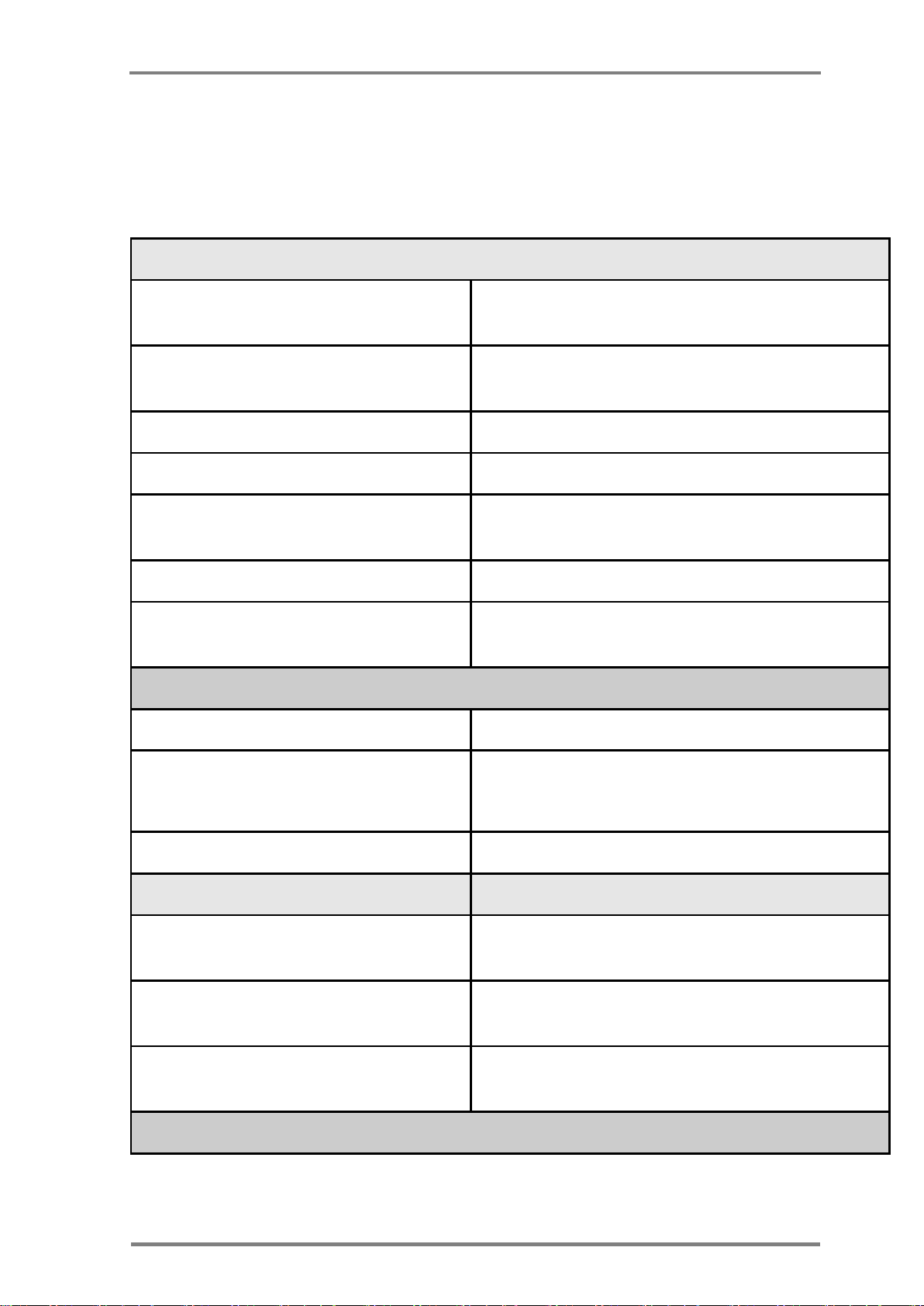
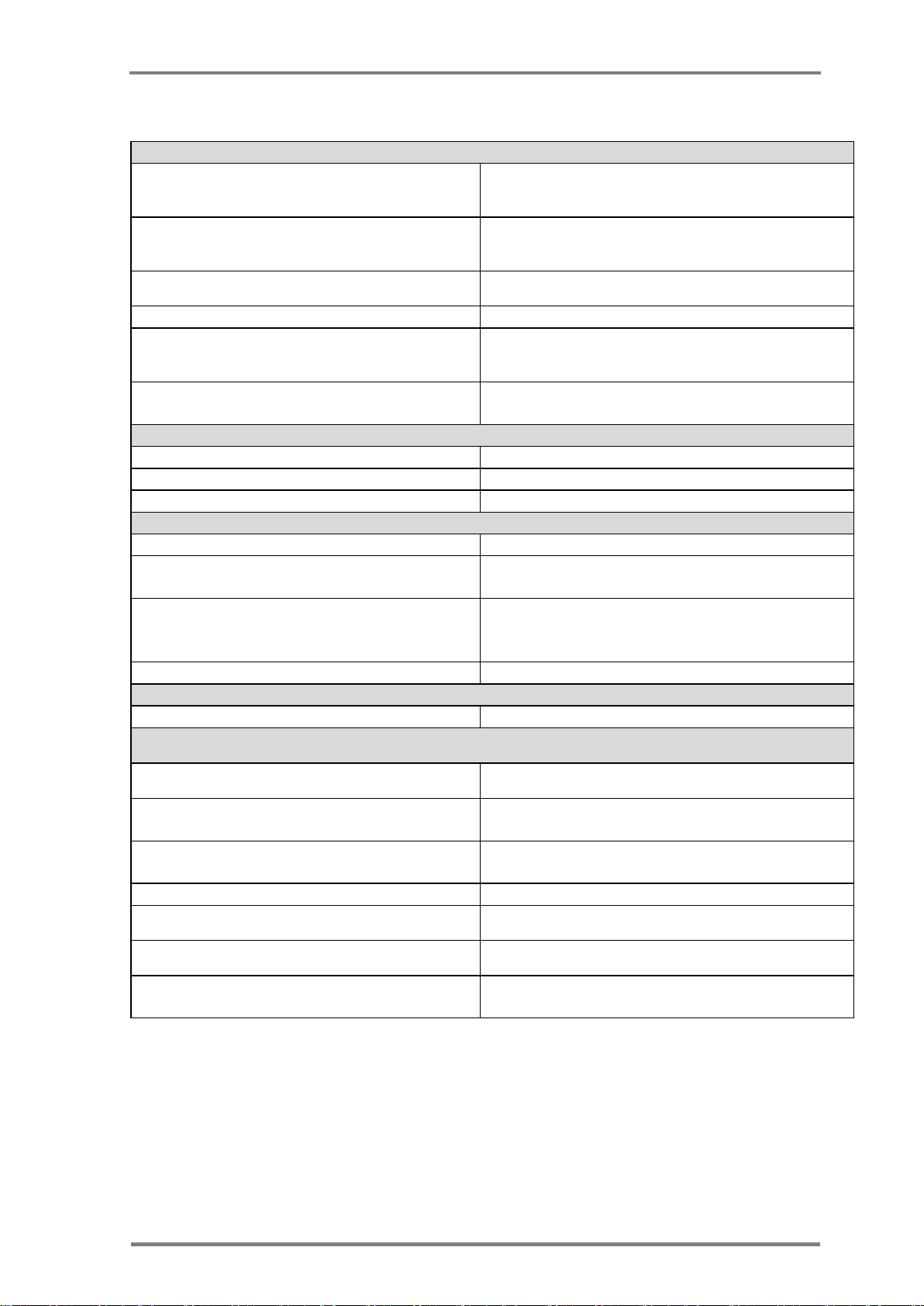
Networking and system Configuration
Communications
Multi-hop, cluster tree wireless sensor
network
Number of Communications
Channels:
Up to four
Multi-hops (Store and Forward)
Up to 15 hops
Network Robustness
Self-healing, adaptive
Temperature Update Rate per WL
sensor
Programmable from 2 min up to 255 min
Max US/RS per USG
1000
Multiple USG (reader) operation
Up to four USG (readers) can coexist in the
same area (i.e. Warehouse)
UHF Network
Operating Frequency
433 MHz ISM band
Maximum rated output power
Less than 0dBm; Matching into 50 Ω
Impedance.
Effective radiated power
Less than 0 dBm
Cellular Network
GPRS Modem
Based on Tellit worldwide certified G24
module.
Frequency bands
Supports Quad band: 850/900/1800/1900
MHz
SIM Card
Integrated SIM card reader for 1.8V or 3.3V,
with an external insert slot.
Ethernet Version
6 Appendices
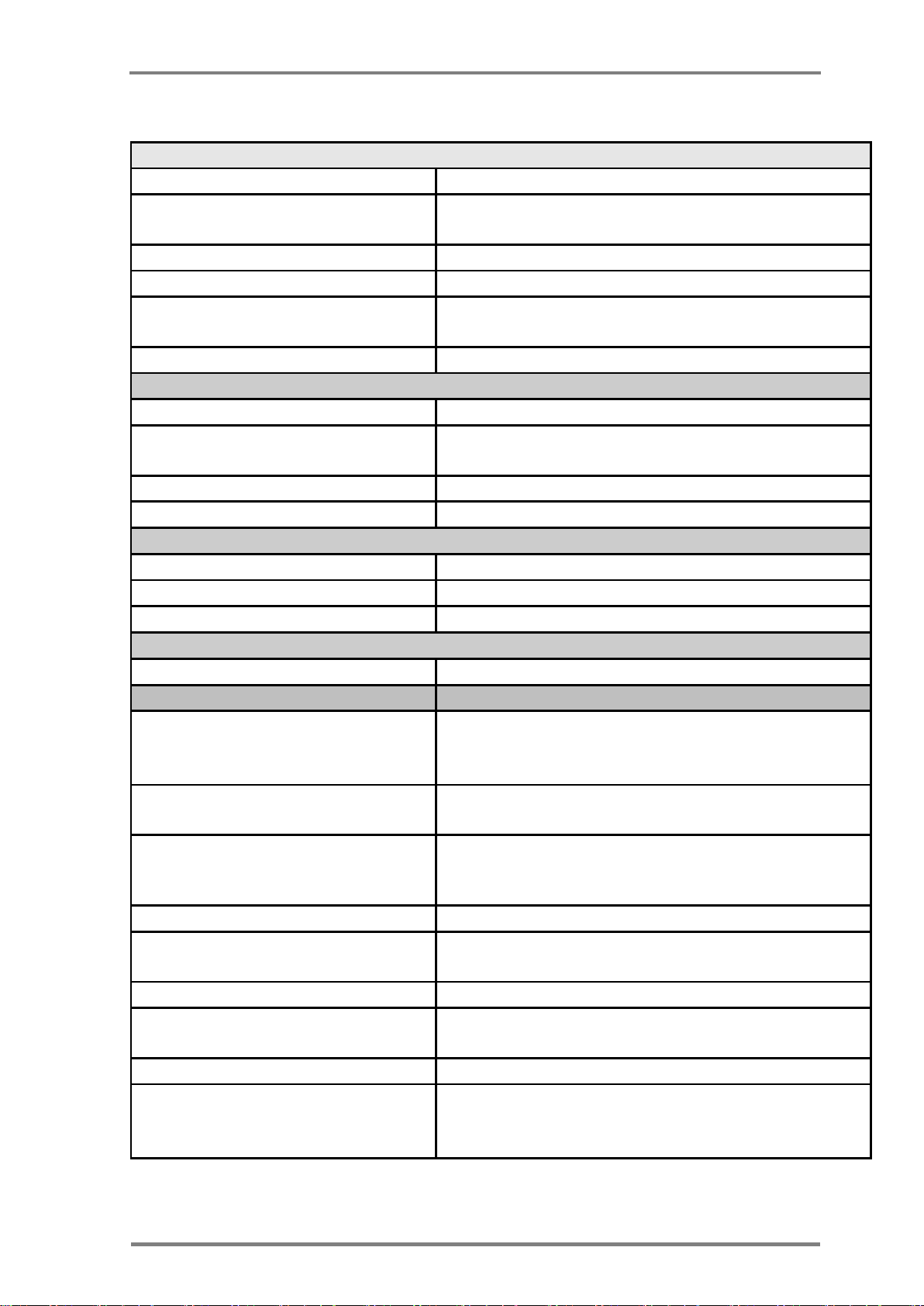
Appendix-A: Product Specifications
A.1: U-Sensor Gateway Specifications
Page 40
U-Sensor Gateway Specifications
30
Version; 1.3
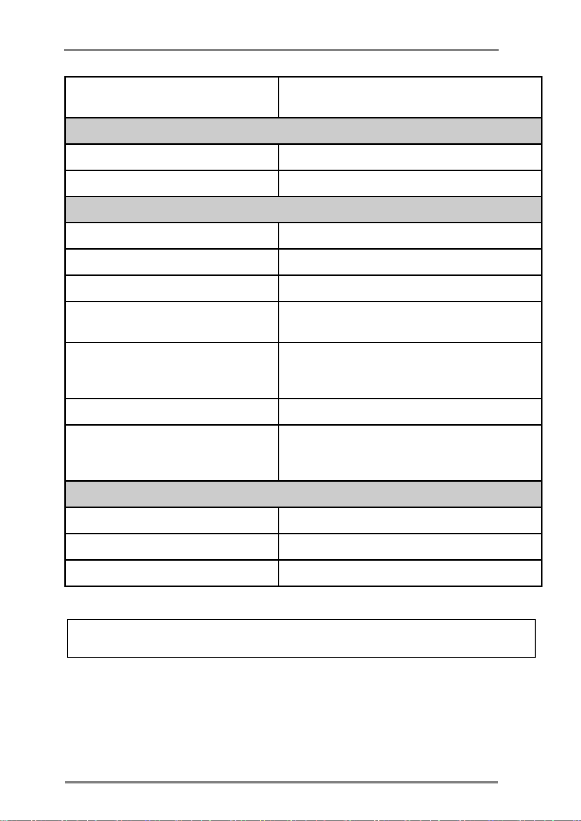
10/100 Mbps (configurable for DHCP and fixed
IP)
GPS
GPS module
Option available on cellular USG only
Antenna
Support for internal / external antenna
PHYSICAL AND ENVIRONMENTAL
Dimensions:
LxWxD – 125 mm x 86 mm x 28 mm
Weight:
233 gram (including battery)
Color:
Black
Operating Temperatures:
-20°C to +06°C battery charge time will
increase in low temperature
Internal Battery power:
LiOn battery pack – 3.7V, 0.8Ah. Support for
up to 9 hours of operation when not
connected to external power if fully charged.
Mobile (Truck) Power:
9-24V operation using lighter power adaptor.
Mains AC External Power:
Using an external 12V DC input from
110/230VA, 50/60 Hz adaptors (supplied with
the USG).
Power
DC power input
9-24 DC
Power Consumption
less than 100 mA at 12V DC input
Indicators
3 LEDS: Red, Green & Yellow
Rechargeable battery life is up to three years. After three years, the gateway should be refreshed
/replaced.
Page 41
Appendices
Installation, Operation & Maintenance of the Wireless Sensing Family
31
Networking and system Configuration
Communications Network
Multi-hop, cluster tree wireless sensor network
Number of Communications
Channels:
Up to four
Multi-hops (Store and Forward)
Up to 15 hops
Network Robustness
Self-healing, adaptive
Temperature measurement Rate
per RS
Remotely programmable from 2 min up to 255
min (default 10 min)
Certifications & Compliances
FCC,CE, WHO, RoHS, EN 12830, EN/UL 60950
UHF Network
Operating Frequency
433 MHz ISM band.
Maximum rated output power
Less than 0 dBm; Matching into 50 Ω
Impedance.
Effective radiated power
Less than 0 dBm
RF Read Range
Up to 500 m per hop in free space
PHYSICAL AND ENVIRONMENTAL
Dimensions:
100 mm x 63 mm x 22 mm
Weight:
70 g
Color:
Grey
Power
DC power input
2 AAA batteries (not included)
Measurement specifications
Maximum measurement Range
Temperature: -35ºC to +65ºC
Relative Humidity: 35% to 100%
(from 0ºC to +60ºC)
Accumulated Operation Time
Over 400 days if connected to the WL network
at 0ºC
Temperature Measurement
Accuracy
±0.5ºC (in the range of -10ºC to +50 ºC)
±0.8ºC (in the range of -35ºC to -10ºC & 50ºC
to +60ºC)
Temperature Resolution
0.1 ºC
Relative Humidity measurement
accuracy
±5%
Relative Humidity Resolution
1%
Memory Capacity
2700 measurement points of each temperature
and relative humidity
Storage Conditions
-20 ºC to +65ºC
Maximum continues temperature
operation range
-20ºC to +60ºC
Special AAA batteries are required for below -20
Celsius operation
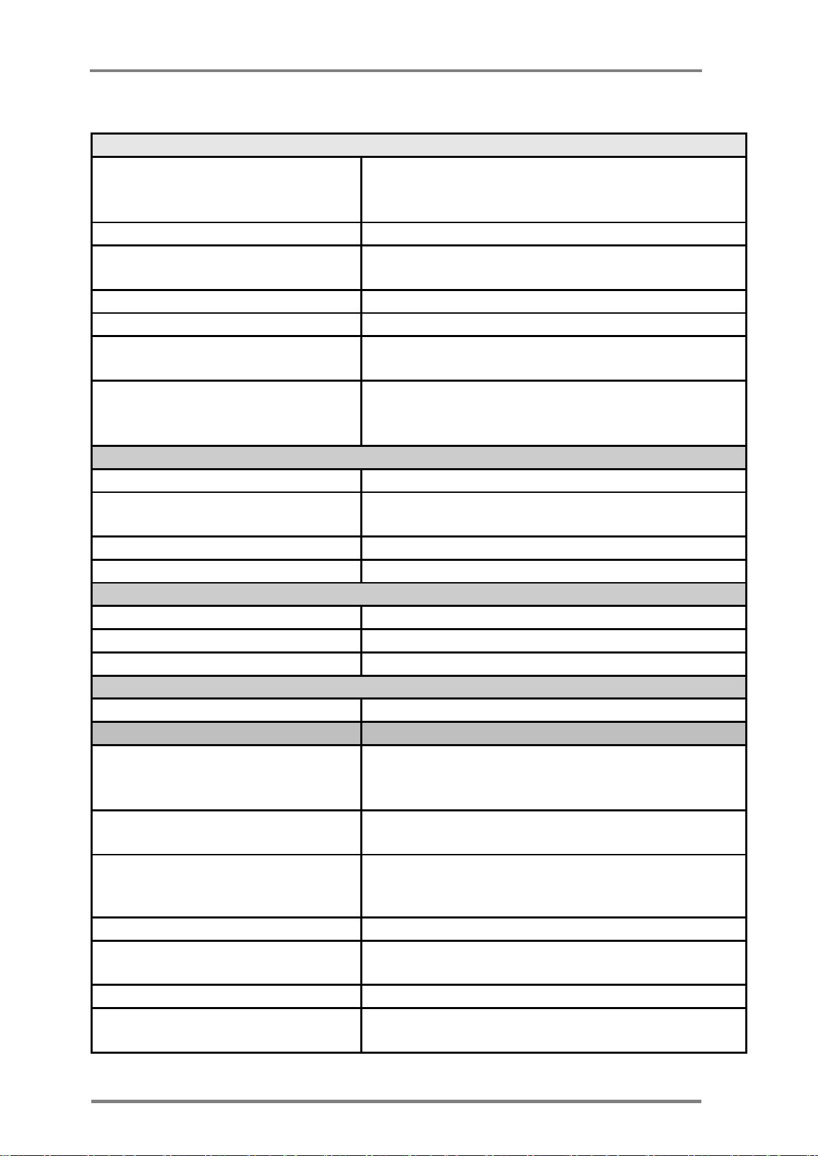
A.2: Resident Sensor Specifications
Page 42
Disposable U-Sensor Specifications
32
Version; 1.3
Networking and system Configuration
Communications Network
(between USG and any Wireless
sensor):
Multi-hop, cluster tree wireless sensor network
Network Topology:
Cluster, mesh-tree
Number of Communications
Channels:
Up to four
Multi-hops (Store and Forward)
Up to 15 hops
Network Robustness
Self-healing, adaptive
Temperature Update Rate per US
Remotely Programmable from 2 min up to 255
min (default 10 min)
Certifications & Compliances
FCC,CE, FDA approved materials for food
contact , ROHS and WEEE compatible materials,
WHO, EN 12830, EN/UL 60950
UHF Network
Operating Frequency
433 MHz ISM band
Maximum rated output power
Less than 0 dBm; Matching into 50 Ω RF
Impedance.
Effective radiated power
Less than 0 dBm
RF Read Range
Up to 500 m per hop in free space
PHYSICAL AND ENVIRONMENTAL
Dimensions:
88 mm x 38 mm x 13 mm
Weight:
26 g
Color:
Blue
Power
Internal batteries
CR2450
Measurement specifications
Maximum measurement Range
Temperature: -35ºC to +65ºC
Relative Humidity: 35% to 100%
(from 0ºC to +60ºC)
Accumulated operation time
Over 160 days if connected to the WL sensor
network at 0ºC, regular battery.
Temperature Measurement
Accuracy
±0.5ºC (in the range of -10ºC to +50 ºC)
±0.8ºC (in the range of-35ºC to -10ºC & 50ºC
to +60ºC)
Temperature Resolution
0.1 ºC
Relative Humidity measurement
accuracy
±5%
Relative Humidity Resolution
1%
Memory Capacity
2700 measurement points of each temperature
and relative humidity
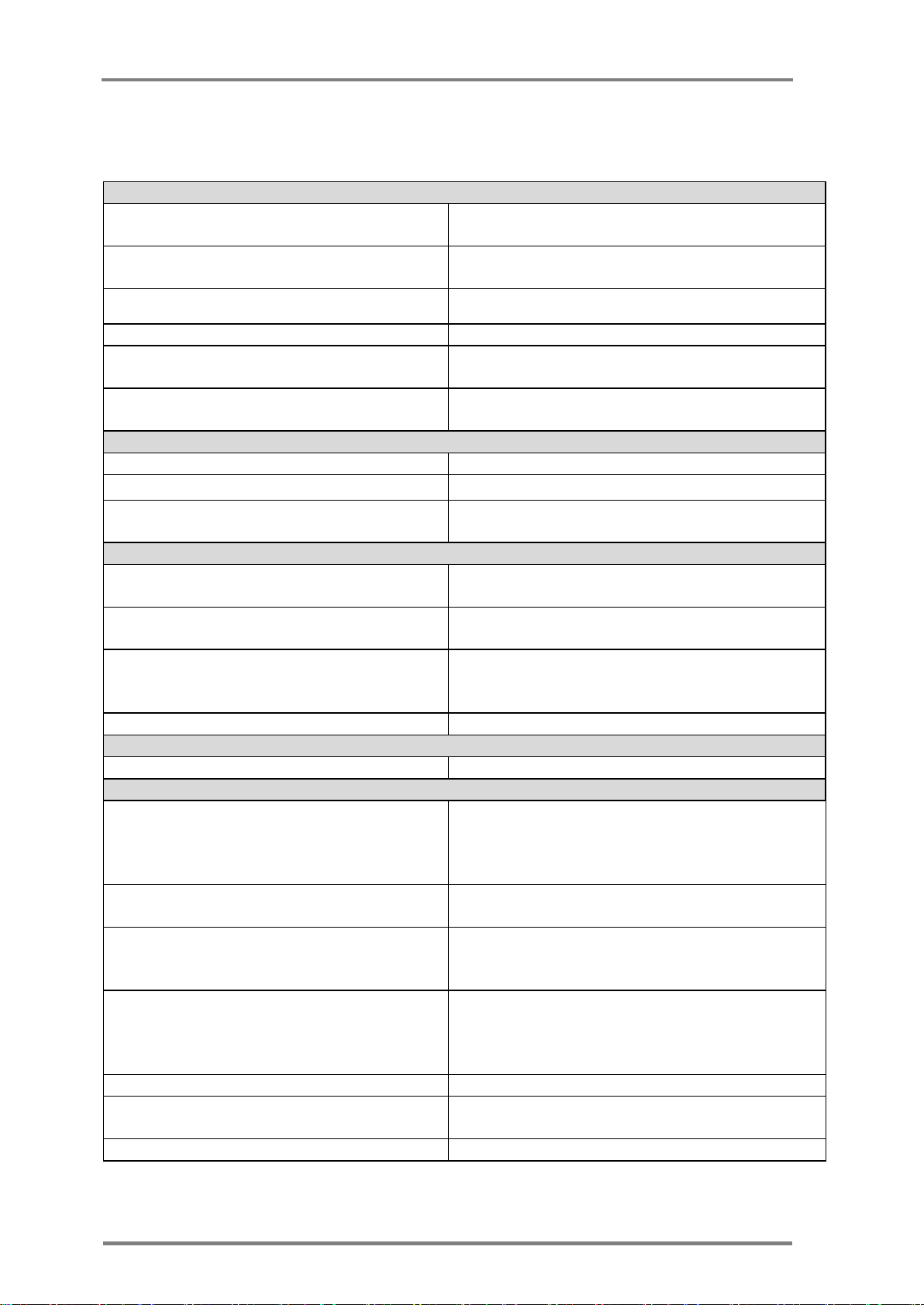
A.3: Disposable U-Sensor Specifications
Page 43

Appendices
Installation, Operation & Maintenance of the Wireless Sensing Family
33
Storage Conditions
0 ºC to +65ºC
Maximum continues Operation
temperature range
-30ºC to +60ºC
(under -20°C the battery life will be reduced)
Page 44
M-Sensor Specifications
34
Version; 1.3
Networking and system Configuration
Communications Network
Multi-hop, cluster tree wireless sensor
network
Number of Communications
Channels:
Up to four
Multi-hops (Store and Forward)
Up to 15 hops
Network Robustness
Self-healing, adaptive
Temperature measurement Rate per
RS
Remotely programmable from 2 min up
to 255 min (default 10 min)
Certifications & Compliances
FCC,CE, WHO, RoHS, EN 12830, EN/UL
60950
UHF Network
Operating Frequency
433 MHz ISM band.
Maximum rated output power
less than 0dBm
RF Read Range
Up to 500 m per hop in free space at -4
dBm
PHYSICAL AND ENVIRONMENTAL
Water-proof
IP67 for temperature only
IP 65 if RH is required
Dimensions:
8.5 x 5 x h21 cm (Without the mount)
9 x 7 x h21.5 cm (Including mount)
Weight:
250gr. (Without the mount, including
batteries)
300gr. (Including mount)
Color:
Grey
Power
DC power input
2 replaceable AA batteries (not included)
Measurement specifications
Maximum measurement Range
(from 0ºC to +60ºC)
Temperature: -35ºC to +65ºC Relative
Humidity: 35% to 100%
Option for 0% to 100% is available with
add-on module
Accumulated Operation Time
Up to 3 years if connected without
battery replacement
Temperature measurement accuracy
±0.5ºC (in range -10ºC to +50 ºC)
±0.8ºC (in range -35ºC to -10ºC & 50ºC
to +60ºC)
Relative Humidity measurement
accuracy
Measurement range: 35% to 100%
accuracy: ±5%
Measurement range with add-on module
: 0% to 100% accuracy: ±3%
Relative Humidity Resolution
1%
Memory Capacity
2500 measurement points of each
temperature and relative humidity
Remote configuration
Product can be configured / programmed
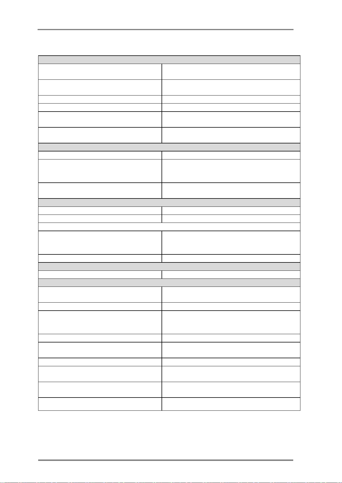
A.4: M-Sensor Specifications
Page 45

Appendices
Installation, Operation & Maintenance of the Wireless Sensing Family
35
Outdoor package
should withstand direct sunlight and
condensation cycles
Storage conditions (without batteries)
-40ºC to +70 ºC
Operating Range (Lithium batteries)
-35ºC to +65 ºC
operation range (Alkaline batteries)
-20ºC to +50ºC
M-Sensor Soil specification
Page 46
36
Version; 1.3
Networking and system Configuration
Communications Network (between
USG and RS & US):
Multi-hop, cluster tree wireless sensor
network
Number of Communications
Channels:
Up to four
Multi-hops (Store and Forward)
Up to 15 hops
Network Robustness
Self-healing, adaptive
Temperature measurement Rate per
RS
Remotely programmable from 2 min up
to 255 min (default 10 min)
Certifications & Compliances
FCC,CE, WHO, RoHS, EN 12830, EN/UL
60950
UHF Network
Operating Frequency
433 MHz ISM band.
Maximum rated output power
Default is less than -4 dBm; Matching
into 50 Ω Impedance. Maximum power
can be configured to 11 dbm
RF Read Range
Up to 500 m per hop in free space at -4
dBm
PHYSICAL AND ENVIRONMENTAL
Water-proof
IP67
Dimensions:
8.5 x 5 x h21 cm (Without the mount)
9 x 7 x h21.5 cm (Including mount)
Weight:
250gr. (Without the mount, including
batteries)
300gr. (Including mount)
Color:
Grey
Power
DC power input
2 replaceable AA batteries (not included)
Measurement specifications
Maximum measurement Range
Soil temperature: -35ºC to +65ºC Soil
moisture: 0 to 239 KPsc
Accumulated Operation Time
Up to 3 years if connected
Temperature measurement accuracy
±0.5ºC (in range -10ºC to +50 ºC)
±0.8ºC (in range -35ºC to -10ºC & 50ºC
to +60ºC)
Temperature Resolution
0.1 ºC
Memory Capacity
2500 measurement points of each
temperature and relative humidity
Remote configuration
Product can be configured / programmed
Storage conditions (without
batteries)
-20ºC to +70 ºC
Operating Range (Lithium batteries)
Soil temperature: -30ºC to +60ºC
Soil Moisture: 10-200 kPa
operation range (Alkaline batteries)
-20ºC to +50ºC
A.5: M-Sensor Soil specification
Page 47
Appendices
Installation, Operation & Maintenance of the Wireless Sensing Family
37
Networking and system Configuration
Communications Network (between
USG and RS & US):
Multi-hop, cluster tree wireless sensor
network
Number of Communications Channels:
Up to four
Multi-hops (Store and Forward)
Up to 15 hops
Network Robustness
Self-healing, adaptive
Temperature measurement Rate per
RS
Remotely programmable from 2 min up
to 255 min (default 10 min)
Certifications & Compliances
FCC,CE, WHO, RoHS, EN 12830, EN/UL
60950
UHF Network
Operating Frequency
433 MHz ISM band.
Maximum rated output power
Less than 0 dBm
RF Read Range
Up to 500 m per hop in free space
PHYSICAL AND ENVIRONMENTAL
Water-proof
IP67
Dimensions:
8.5 x 5 x h21 cm (Without the mount)
9 x 7 x h21.5 cm (Including mount)
Weight:
250gr. (Without the mount, including
batteries)
300gr. (Including mount)
Color:
Grey
Power
DC power input
2 replaceable AA batteries (not included)
Measurement specifications
Accumulated Operation Time
Up to 3 years if connected
Photosynthetic Photon Flux (PPF)
Range
–0 - 2000 μmol m-2 s-1
Memory Capacity
2500 measurement points of each
temperature and relative humidity
Remote configuration
Product can be configured / programmed
Storage conditions (without batteries)
-20ºC to +70 ºC
Operating Range (Lithium batteries)
Temperature: -30ºC to +60ºC
operation range (Alkaline batteries)
-20ºC to +50ºC (higher temperature
available from several battery vendors)
A.6: M-Sensor (A-Sensor Sun) specification
Page 48

Installation assumptions
38
Version; 1.3
Appendix-B: Ethernet USG installation and setup process
The installation process installs XPORT USG at customer premises.
B.1: Installation assumptions
The installation process is based on the assumptions that:
USG is defined in the Amplia server.
Lancusrouter is running at known IP port.
Communication server is running.
There is a network with DHCP server in the site.
B.2: Tools
The installation process and the trouble shooting require the following tools:
Laptop
Ethernet cable to connect the USG to Laptop directly.
Lantronix DeviceInstaller software installed.
ZOC terminal software
6
.
B.3: Starting the installation
Connect the USG to the network via the Ethernet cable and power it on. The
expected sequence as reflected by the LEDs is: all LEDs are on - means that
the USG is has connected to the server and after that the green LED blinks. If
this is the case, the installation ends here and the activity of the USG can be
monitored by the browser thru the web interface
6
See - http://www.emtec.com/zoc/.
Page 49

Appendices
Installation, Operation & Maintenance of the Wireless Sensing Family
39
B.4: Trouble shooting
B.4.1: Check connectivity with the USG
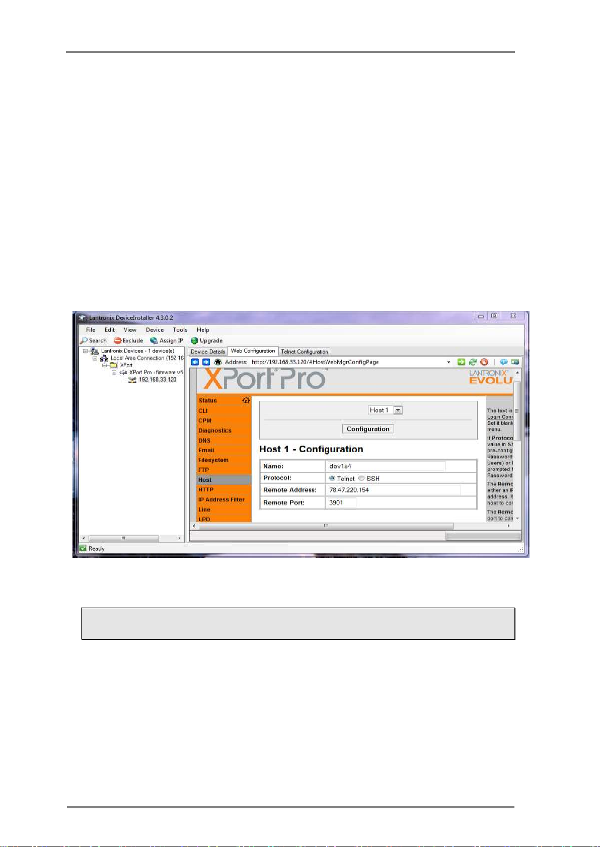
Open Device Installer and search for the USG. If the USG is found the result
looks like the following:
Figure 18: Device search status
o If the device is not found, connect the device by the Ethernet
cable directly to the laptop and search the USG again.
If connected, then check the network, probably the laptop
and the USG are not on the same network.
o If not connected, check Ethernet cable and laptop network
settings.
Page 50
Trouble shooting
40
Version; 1.3
o Reset XPORT to defaults
o Turn off the USG
o Put all the DIP switch in the "on" position
o Turn on the USG.
o Wait one minute.
o Turn off the USG
o Turn the DIP switches off again,
o power the USG on
o Try to connect to DeviceInstaller again. If this time the connection
is established, use the Web Configuration (select the web
configuration tab in the device installer application) to configure
lancusrouter’s host and continue from start.
If still the USG does not connect the installation with this
device failed. Contact CartaSense for further support
Assuming the USG is connected to the DeviceInstaller the following should be
validated.
Figure 19: lancusrouter configuration
B.4.2: Network connectivity
B.4.3: DHCP
Page 51
Appendices
Installation, Operation & Maintenance of the Wireless Sensing Family
41
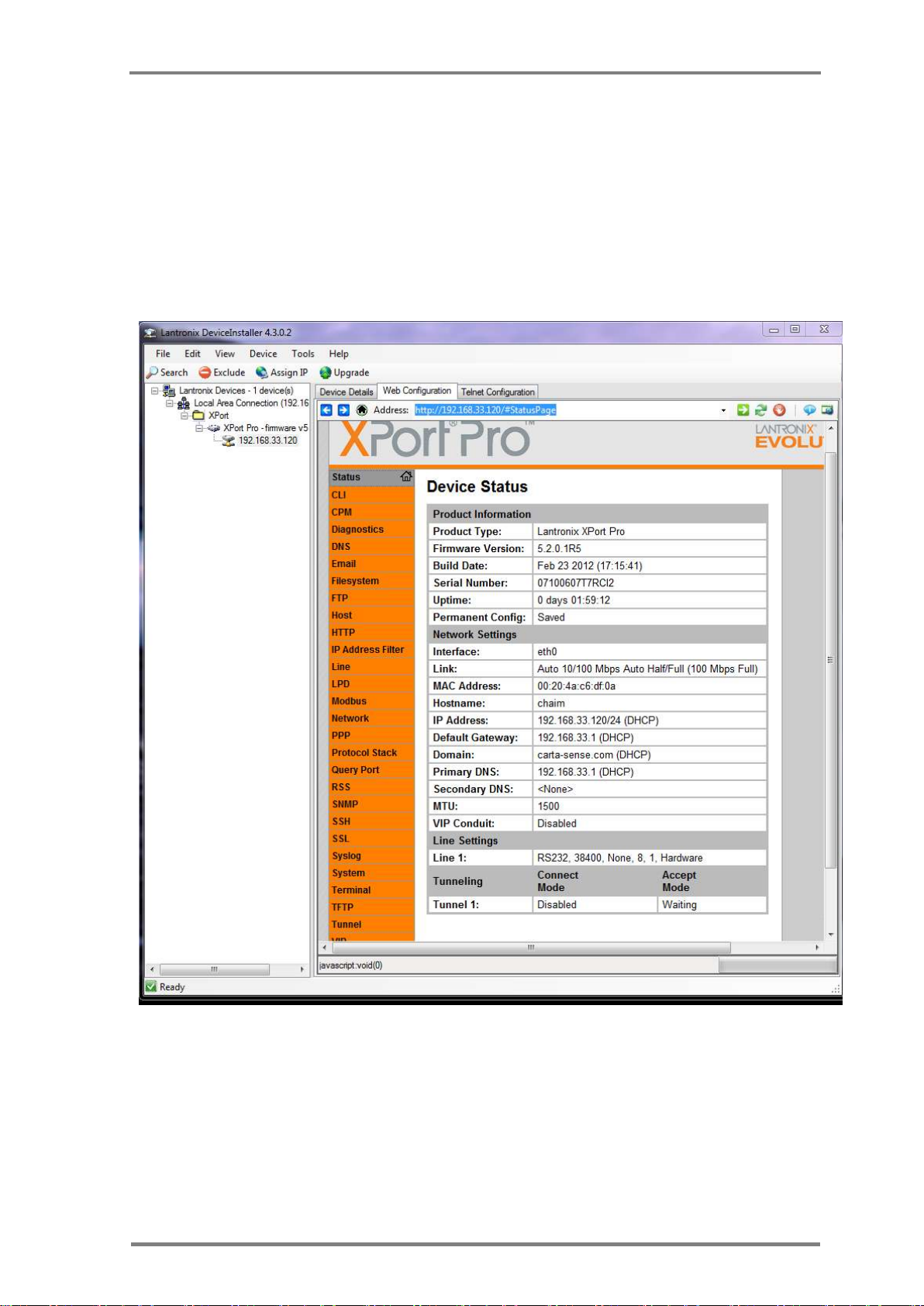
The USG is configured to obtain its IP address gateway and DNS server from
the DHCP server, By comparing network status provided by the
DeviceInstaller and laptop configuration by using the command “ipconfig /all”
we have all the information we need to do this test.
The IP of the USG and the IP of the laptop should belong to the same
subnet.
The USG and the laptop should have the same Gateway and DNS
server.
Figure 20: Device Status
Page 52

Trouble shooting
42
Version; 1.3
Windows IP Configuration
Host Name . . . . . . . . . . . . : hbelfer-dell
Primary Dns Suffix . . . . . . . :
Node Type . . . . . . . . . . . . : Hybrid
IP Routing Enabled. . . . . . . . : No
WINS Proxy Enabled. . . . . . . . : No
DNS Suffix Search List. . . . . . : carta-sense.com
Ethernet adapter Local Area Connection:
Connection-specific DNS Suffix . : carta-sense.com
Description . . . . . . . . . . . : Realtek PCIe FE Family Controller
Physical Address. . . . . . . . . : 24-B6-FD-1F-0A-E8
DHCP Enabled. . . . . . . . . . . : Yes
Autoconfiguration Enabled . . . . : Yes
Link-local IPv6 Address . . . . . :
fe80::4c55:30fa:f4d1:d53f%13(Preferred)
IPv4 Address. . . . . . . . . . . : 192.168.33.129(Preferred)
Subnet Mask . . . . . . . . . . . : 255.255.255.0
Lease Obtained. . . . . . . . . . : Tuesday, May 22, 2012 8:21:59 AM
Lease Expires . . . . . . . . . . : Wednesday, May 23, 2012 8:21:59 AM
Default Gateway . . . . . . . . . : 192.168.33.1
DHCP Server . . . . . . . . . . . : 192.168.33.1
DHCPv6 IAID . . . . . . . . . . . : 287618813
DHCPv6 Client DUID. . . . . . . . : 00-01-00-01-16-D0-EB-20-24-B6-FD-1F-
0A-E8
DNS Servers . . . . . . . . . . . : 192.168.33.1
Primary WINS Server . . . . . . . : 192.168.33.1
NetBIOS over Tcpip. . . . . . . . : Enabled
Figure 21: Windows IP configuration
In case the DHCP failed to allocate network parameters correctly, static
configuration is required.
B.4.4: Static configuration
To configure static IP do the following steps:
o Select manually IP address which is not owned by any host.
o Select gateway DNS server and subnet mask similar to “ipconfig
/all”
o Select Assign IP by the DeviceInstaller.
o Select “Assign a specific IP address”
o Select Next and fill IP address,Subnet mask and Default gateway.
o Select Next and Assign .
Now reboot the USG and see if it connects.
Page 53
Appendices
Installation, Operation & Maintenance of the Wireless Sensing Family
43
B.4.5: Check connectivity with lancusrouter
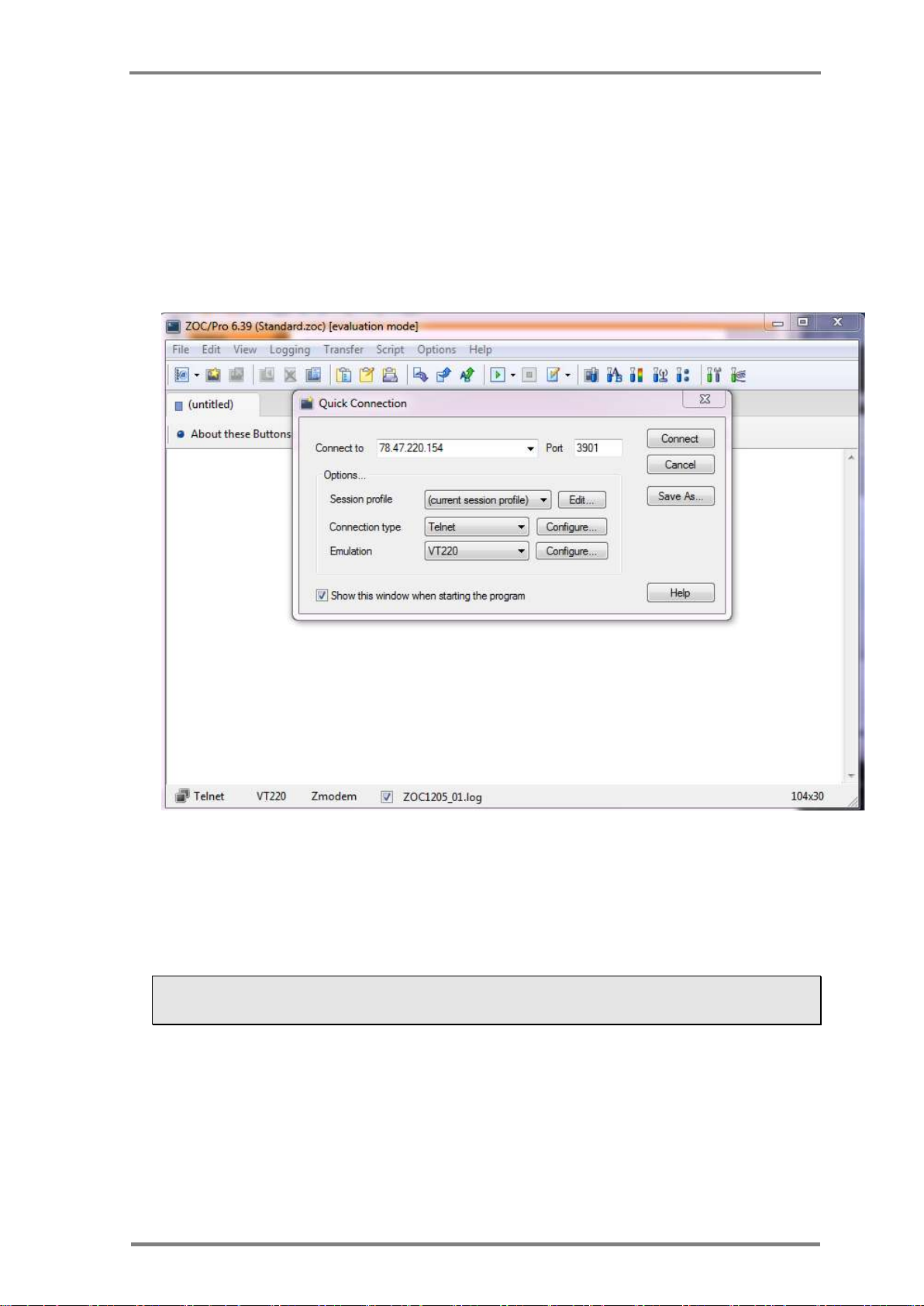
In case the USG is configured properly and still fails to connect the
lancusrouter, use laptop’ terminal to connect . Most terminal software will
do the job . The ZOC terminal will be used to demonstrate connectivity
test. The screenshot below presents testing to the lancusrouter of the
development server. IP 78.47.220.154 port 3901 .
Figure 22: Terminal connection test with lancusrouter
Press connect and when the status bar indicates connection, press Z
character. This indicates the lancusrouter to enter echo mode in which it
returns any received character.
If this process fails the problem relates to firewall policy
which should be handled by the hosting company’s IT.
When this problem is resolved, the connectivity problem will be also be
resolved.
Page 54
Creating Log Files
44
Version; 1.3
Appendix-C: Creating Log Files
To create the log file it is required to have any software which monitors
ports like Putty or RealTerm7.
Before you begin, turn off the USG by activating the On/Off button
Follow the steps below to create the required log file:
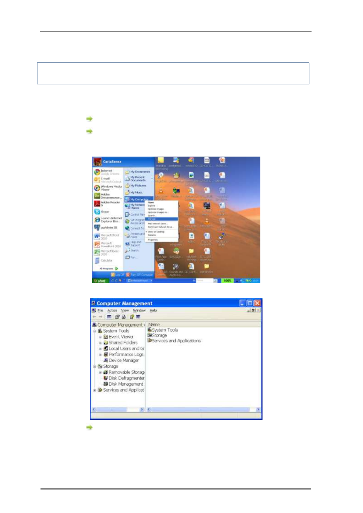
Right click on My Computer. Go to Manage.
On Windows 7 /8; press the window key, type "computer"
and then press enter. Once the computer window is up, click
on "computer" and then click on "manage
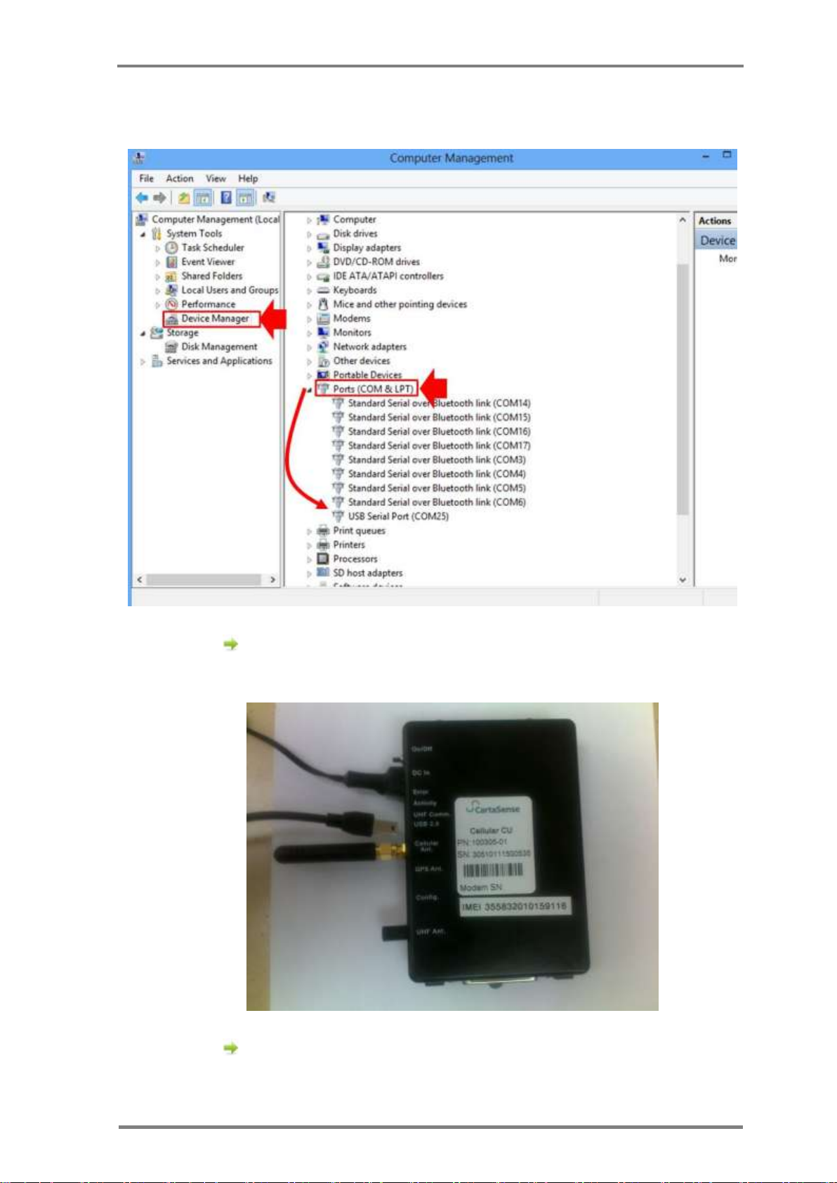
Click on Device Manager. On the right hand side of the
screen look for Ports and expand it. If you don't see it, just
7
May be downloaded from http://realterm.sourceforge.net/
Page 55
Appendices
Installation, Operation & Maintenance of the Wireless Sensing Family
45
leave the screen visible at the place of the word port in
alphabetical order.
Figure 23: Device manager screen
To be able to see the port number of the Gateway, connect a
USB cable between front panel of the gateway (11) and
computer. (see Figure 24).
Figure 24: USB connection
Turn on the Gateway by activating the on/off switch (6).
Take a look at the port manager on your desktop. You will
Page 56
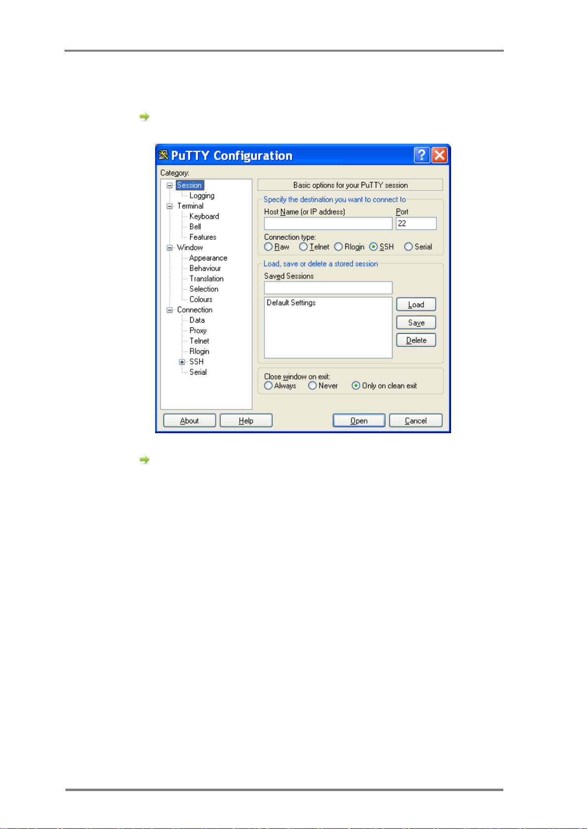
Creating Log Files
46
Version; 1.3
notice that the port number is added. This is the Gateway
port number.
The log file creation is demonstrated using the Putty
software. Open Putty software.
Figure 25: Putty software screen
Click session from the list on the left side of the screen.
Page 57
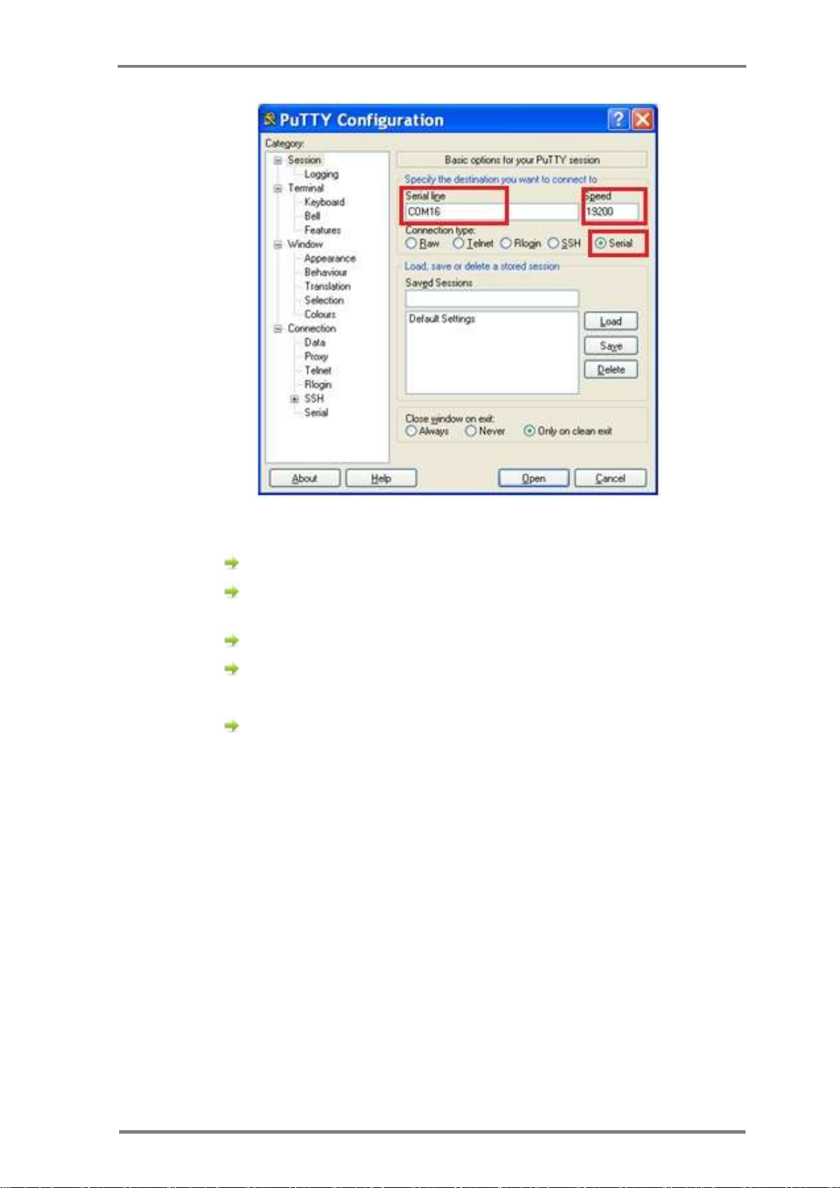
Appendices
Installation, Operation & Maintenance of the Wireless Sensing Family
47
Figure 26: Putty software Session screen
Click Serial radio button on the right.
Type the COM port number in Serial Line Field. In this
example the COM port number is 16.
In the Speed field type 19200
Click Logging from the list on the left (see Figure 27).
Choose All session output radio button from the list on the
right
Page 58
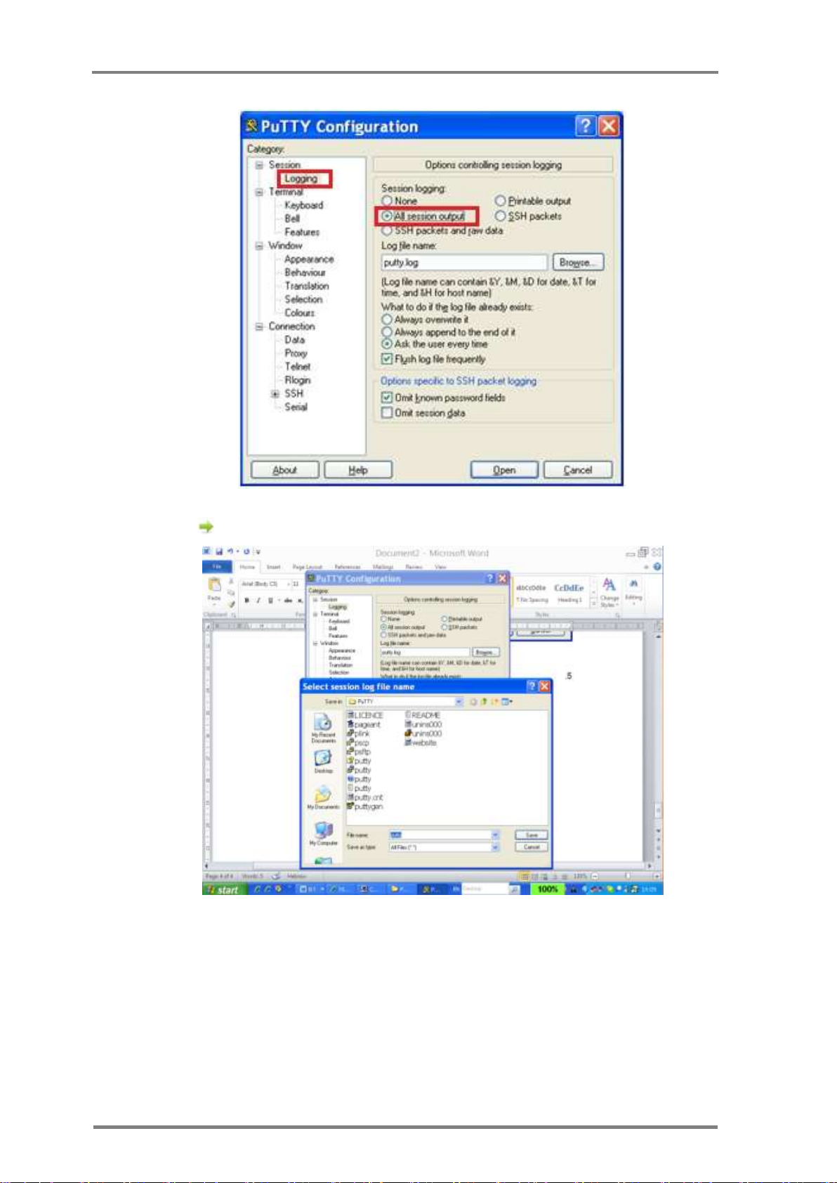
Creating Log Files
48
Version; 1.3
Figure 27: Putty software Logging screen
Browse to choose the log file location.
Figure 28: Insert log file location
Page 59
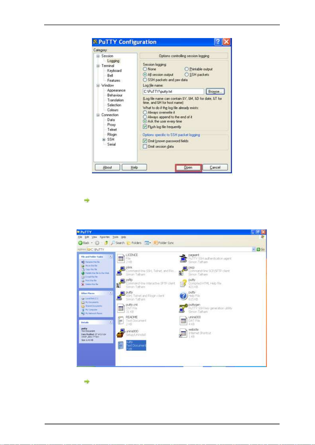
Appendices
Installation, Operation & Maintenance of the Wireless Sensing Family
49
Figure 29: Opening log data
Click Open button from the bottom of the screen. A black
window opens. The log data appear on the screen, but also
saved to a file. Search for the file name you created in the
place you chose to store it.
This log file should be sent to CartaSense support team
Figure 30: Opening log file
Page 60

FAQ
50
Version; 1.3
Appendix-D: FAQ
Q: What are the differences between U-Sensor and R-Sensor?
A: U-Sensors
U-Sensors are used on each pallet to monitor the product itself. U-Sensors
are disposable. The life time of a U-sensor is up to 160 days (at 0ºC).
Resident Sensors
Resident Sensors are used for environmental monitoring and as repeaters
to boost UGS reception.
Resident Sensors are multiuse. Each resident Sensor holds two AAA
batteries which can be replaced. The life time of a Resident Sensor is up
to one year.
Q: When should I use R-Sensor?
A: Resident Sensors are used when:
An environmental monitoring is required.
The area that needs to be covered has blockers. In this case
Resident Sensors can be used as repeaters to boost UGS reception.
Q: What happens to the measurements when a USG is not
available and sensors are active?
A: As long as there is no connection with a gateway, all data measured by
the Wireless Sensors is stored in each sensor's memory. Once the sensors
identify a gateway to connect to, all data is transmitted to the gateway.
Q: Can I get an Ethernet USG with GPS option?
A: The GPS option is available only for cellular USG units.
Q: How do I decide if to use Ethernet USG or Cellular USG in my
application?
A: Ethernet USG is used when there is a stationary installation and the
USG is not mobile (like in a warehouse) and a LAN connection is available
in the monitored site.
Page 61

Appendices
Installation, Operation & Maintenance of the Wireless Sensing Family
51
A cellular USG is used for mobile applications, like trucks and trailers,
where LAN or Ethernet connectivity is rarely available.
In some cases, networking setup (like firewall), can cause delay in
deployment. In that case, cellular units provide the easiest way to get a
system up and running independent of the local IT configuration.
Q: When should I use the Cellular USG in stationary application?
A: A cellular USG can be used in a stationary installation when a LAN
connection is not available.
Q: How do I know how many R-Sensor to use in a stationary
application?
A: Number of Resident Sensors varies between sites. It depends on
communication blockers such as Metal doors, concrete walls, racks,
architecture, level of fluids in the products. The toughest the blockers the
more Resident Sensors you need in order to bypass the blockers.
Q: How do I know the battery level & status of the R-Sensor ?, USensor
A: CartaSense system provides statuses of the various system
components. One of them is the battery status. Status data is stored in
the database. When integrating CartaSense system, the application
developer can use the data for any manipulation required such as battery
status display, setting thresholds, alarms, etc.
Q: Can the interval between measurements be changed?
A: yes. The measurements time interval can be changed either remotely
or during manufacturing procedure.
Q: In a cellular USG, what will be the data traffic?
A: A single sensor generates around 120KB per month. In truck
installations with 30 U-Sensors, the average traffic is 3.5 MB per month.
Traffic values may vary depending on number of sensors, measurements
time interval, etc.
Page 62

FAQ
52
Version; 1.3
Q: Does CartaSense offer its own SIM for the cellular USG?
A: Yes. CartaSense offers a SIM card (optional). The user will be charged
on a monthly basis.
Q: How do I decide what SIM company to choose?
A: The cellular data market is highly developed and there are offerings
from operators and specialized MVNOs and dealers. Specifically, based on
the application (static / roaming) the best deal should be sought.
It is recommended to purchase a bulk of data and that will be divided
among the SIM cards upon use.
Q: Looks like GPS information is not accurate, what can be the
cause?
A: It might be a problem with the antenna reception. It is required to
make sure that the antenna is located in a place which has an outside
connection. Sometimes the antenna might be located in a place with no
reception, such as a tunnel or underground parking. There are areas
where GPS satellites are not availability.
Q: Can I program the mode of connecting the cellular USG to the
network? (Default is always on)
A: Yes. Cellular connection might be either always on (this is the default)
or open each time the system transmits data and then close the
connection.
Page 63

Appendices
Installation, Operation & Maintenance of the Wireless Sensing Family
53
Appendix-E: Regulatory notices
FCC / Industry Canada
This device complies with FCC Rules Part 15 and with Industry Canada
license-exempt RSS standard(s). Operation is subject to two conditions: (1)
This device may not cause harmful interference, and (2) this device must
accept any interference that may be received or that may cause undesired
operation.
Industry Canada
Le présent appareil est conforme aux CNR d'Industrie Canada applicables aux
appareils radio exempts de licence. L'exploitation est autorisée aux deux
conditions suivantes : (1) l'appareil ne doit pas produire de brouillage, et (2)
l'utilisateur de l'appareil doit accepter tout brouillage radioélectrique subi,
même si le brouillage est susceptible d'en compromettre le fonctionnement.
Class B digital device
NOTE: This equipment has been tested and found to comply with the limits
for a Class B digital device, pursuant to part 15 of the FCC Rules. These limits
are designed to provide reasonable protection against harmful interference in
a residential installation. This equipment generates uses and can radiate
radio frequency energy and, if not installed and used in accordance with the
instructions, may cause harmful interference to radio communications.
However, there is no guarantee that interference will not occur in a particular
installation. If this equipment does cause harmful interference to radio or
television reception, which can be determined by turning the equipment off
and on, the user is encouraged to try to correct the interference by one or
more of the following measures:
-Reorient or relocate the receiving antenna.
-Increase the separation between the equipment and receiver.
-Connect the equipment into an outlet on a circuit different from that to
which the receiver is connected.
-Consult the dealer or an experienced radio/TV technician for help.
Page 64

Regulatory notices
54
Version; 1.3
Changes or modifications to this equipment not expressly approved
by the party responsible for compliance (CartaSense Ltd.) could void
the user’s authority to operate the equipment.
 Loading...