

CartaSense LANUSG01 User Manual
CartaSense Ltd.
Manual for the
Installation, Operation & Maintenance
Of the
Wireless Sensing Product Family
Version; 1.3 Nov. 2013


i
The material in this document is the proprietary of
CartaSense Ltd.
Any unauthorized reproduction, use or disclosure of this
material, or any part thereof, is strictly prohibited.
This material is meant solely for the use of CartaSense Ltd.
employees and authorized CartaSense Ltd. customers
Legal Notice
Disclaimer and Limitation of Liability
CartaSense Ltd. and its affiliates, officers, directors, employees and agents
provide the information contained in this Manual on an “as-is” basis and do
not make any express or implied warranties or representations with respect
to such information including, without limitation, warranties as to non-
infringement, reliability, fitness for a particular purpose or application,
usefulness, completeness or accuracy.
CartaSense Ltd. shall not in any circumstances be liable to any person for any
special, incidental, direct, indirect or consequential damages, including
without limitation, damages resulting from use of or reliance on information
presented herein, or loss of profits or revenues or costs of replacement
goods, even if informed in advance of the possibility of such damages.
ii
Style Conventions
Convention
Used for
Verdana
Regular text
Arial Italics
Special terms
Monospace
Text entered by the user
Action
Notes, to draw attention and provide solutions
to specific issues.
Comments & Suggestions
Customer suggestions are important to us and enable us to
improve our documentation, making it more useful to you.
Please e-mail any comments about this guide or any other of
CartaSense documentation to:
info@cartasense.com
Please include the following information with your comments:
Document title:
Page number:
Your name and organization (optional)
The following Table lists conventions that are used throughout this guide.
Contact Information
Address any technical questions or problems to CartaSense Ltd.
Address: 6 Ravnitzki St., Petach Tikva 49277, ISRAEL
Tel: +972-3-943-1543
Fax: +972-3-930-0877
Email: info@cartasense.com
Website: www.cartasense.com

Installation, Operation & Maintenance of the Wireless Sensing Family
iii
Term
Definition
AAA
Triple A – Battery standard size
Abbr.
Abbreviated term
AC
Alternate Current (Abbr.)
APN
Access Point Name
CS
Communication Server
DC
Direct Current
FAKRA
UHF RF Antenna connector of the USG
GPRS
General Packet Radio Service is a packet oriented mobile data service
available to all users of the 2.5G cellular communication GSM systems
GSM
Global System for Mobile communications (Cellular Standard)
LAN
Local Area Network
LED
Light Emitting Diode (Indicators of the USG and the AC adapter)
M
Million (1,000,000)
MCC
Mobile Country Code
MHz
Mega-Hertz – 1M Hertz (Hertz - radio frequency unit)
mm
Millimeters (1/1000 m)
MNC
Mobile Network Code
PASSWORD
APN's password
RF
Radio Frequency
RH
Relative humidity
RS
Resident Sensor, CartaSense resident wireless sensor
UHF
Ultra High Frequency
US
U-Sensor, CartaSense disposable wireless sensor
USERNAME
APN's username
USG
U-Sensor Gateway, CartaSense Wireless Sensor Gateway
V
Voltage
Wi-Fi
A Wireless LAN (Abbr. for Wireless Fidelity)
Terms and Definition
Captions, abbreviations and definitions used throughout this document are
presented herein.

iv
Table of Content
Legal Notice .............................................................................................................. i
Terms and Definition .................................................................................................. iii
1 System Description ...............................................................................................1
1.1 Introduction ............................................................................................................ 1
1.2 System Overview .................................................................................................... 1
1.3 Web application ...................................................................................................... 2
2 Product description ...............................................................................................4
2.1 U-Sensors (US) ........................................................................................................ 4
2.1.1 Operating the U-Sensor ............................................................................................................. 4
2.1.1.1 Activation of the US .......................................................................................................... 5
2.1.2 U-Sensor LED Indications ........................................................................................................... 5
2.2 M-Sensor (Air) ......................................................................................................... 5
2.2.1 Deployment of the M-Sensor (Air) ............................................................................................ 6
2.2.1.1 Assembly of the M-Sensor (Air) ........................................................................................ 6
2.2.1.2 Activation of the M-Sensor (Air) ....................................................................................... 6
2.2.1.3 Operation of the M-Sensor (Air) ....................................................................................... 6
2.3 M-Sensor Soil .......................................................................................................... 7
2.3.1 Deployment of the Soil Sensor .................................................................................................. 7
2.3.1.1 Assembly of the Soil-Sensor .............................................................................................. 7
2.3.1.2 Activation of the Soil -Sensor ............................................................................................ 7
2.3.1.3 Operation of the Soil Sensor ............................................................................................. 7
2.4 M-Sensor Sun .......................................................................................................... 7
2.4.1 Deployment of the M-Sensor Sun (A-Sensor Sun) ..................................................................... 8
2.4.1.1 Assembly of the Sun-Sensor.............................................................................................. 8
2.4.1.2 Activation of the Sun -Sensor ............................................................................................ 8
2.4.1.3 Operation of the Sun Sensor ............................................................................................. 8
2.5 Resident Sensor (RS) ............................................................................................... 8
2.5.1 Deployment of the Resident Sensor .......................................................................................... 9
2.5.1.1 R-Sensor Assembly ............................................................................................................ 9
2.5.1.2 RS activation and visual indications ................................................................................ 10
2.6 U-Sensor Gateway ................................................................................................. 10
2.6.1 Deployment of the USG ........................................................................................................... 11
2.6.1.1 Assembly of the USG ....................................................................................................... 12
2.6.1.2 Activating the USG .......................................................................................................... 12
2.6.2 U-Sensor Gateway Backup power ........................................................................................... 13
2.6.3 SIM Card Requirements ........................................................................................................... 14
2.6.3.1 SIM card APN .................................................................................................................. 14
3 Installation and operation .................................................................................. 15
3.1 Pre-installation Preparations ................................................................................. 15

Installation, Operation & Maintenance of the Wireless Sensing Family
v
3.1.1 Tools ........................................................................................................................................ 15
3.2 Site Survey ............................................................................................................ 16
3.2.1 Warehouse .............................................................................................................................. 16
3.2.2 Truck and trailer....................................................................................................................... 16
3.3 Mounting, installing and interconnecting ............................................................... 16
3.3.1 Pre-Installation Check List........................................................................................................ 16
3.3.2 Rules of “thumb” for locating wireless equipment ................................................................. 17
3.3.3 Equipment placement ............................................................................................................. 17
3.3.3.1 General Considerations for USG location ....................................................................... 17
3.3.3.2 Recommended Workmanship and Tips for Fixed USG Installation ................................ 18
3.3.3.3 Installation of Ethernet USG ........................................................................................... 18
3.3.4 U-Sensor Gateway setup ......................................................................................................... 19
3.3.5 U-Sensor Gateway activation .................................................................................................. 20
3.3.6 Resident Sensor activation ...................................................................................................... 21
3.3.7 Placement of wireless U-sensors ............................................................................................. 21
3.4 Mounting the wireless equipment ......................................................................... 22
3.4.1 U-Sensor Gateway wall Mount ................................................................................................ 22
3.4.2 Truck installation ..................................................................................................................... 24
3.4.3 R-sensor installation ................................................................................................................ 25
3.4.4 Mounting the M-Sensor: ......................................................................................................... 25
4 Web Application test utility ................................................................................ 26
5 Troubleshooting ................................................................................................. 27
5.1 Introduction .......................................................................................................... 27
5.2 Problems .............................................................................................................. 27
6 Appendices ........................................................................................................ 29
Appendix-A: Product Specifications ........................................................................... 29
A.1: U-Sensor Gateway Specifications ............................................................................... 29
A.2: Resident Sensor Specifications ................................................................................... 31
A.3: Disposable U-Sensor Specifications ............................................................................ 32
A.4: M-Sensor Specifications ............................................................................................. 34
A.5: M-Sensor Soil specification ........................................................................................ 36
A.6: M-Sensor (A-Sensor Sun) specification ....................................................................... 37
Appendix-B: Ethernet USG installation and setup process .......................................... 38
B.1: Installation assumptions ............................................................................................ 38
B.2: Tools ......................................................................................................................... 38
B.3: Starting the installation.............................................................................................. 38
B.4: Trouble shooting........................................................................................................ 39
B.4.1: Check connectivity with the USG ................................................................................................ 39
B.4.2: Network connectivity ................................................................................................................. 40
B.4.3: DHCP ........................................................................................................................................... 40

vi
B.4.4: Static configuration ..................................................................................................................... 42
B.4.5: Check connectivity with lancusrouter ........................................................................................ 43
Appendix-C: Creating Log Files ................................................................................... 44
Appendix-D: FAQ ....................................................................................................... 50
Appendix-E: Regulatory notices ................................................................................. 53
Table of Figures
Figure 1: Typical system architecture ...................................................... 2
Figure 2: U sensor ................................................................................ 4
Figure 3: M-Sensor, Air – front & rear view .............................................. 6
Figure 5: A-sensor soil ........................................................................... 7
Figure 6: M-Sensor Sun ......................................................................... 8
Figure 7: Resident Sensor top & side view ................................................ 9
Figure 8: Resident Sensor - bottom view ................................................. 9
Figure 9: Ethernet U-Sensor Gateway .....................................................11
Figure 10: GPS- GPRS U-Sensor Gateway ...............................................11
Figure 11: Typical equipment allocation in a warehouse ............................19
Figure 12: USG mount drill scheme ........................................................22
Figure 13: Vertical USG installation ........................................................23
Figure 14: Horizontal USG installation ....................................................23
Figure 15: Resident sensor mounting .....................................................24
Figure 16: RS with USG and UHF Antenna using single mounting ..............24
Figure 17: Dashboard USG unit .............................................................25
Figure 17: M-sensor holder ...................................................................25
Figure 18: Device search status .............................................................39
Figure 19: lancusrouter configuration .....................................................40
Figure 20: Device Status .......................................................................41
Figure 21: Windows IP configuration ......................................................42
Figure 22: Terminal connection test with lancusrouter ..............................43
Figure 23: Device manager screen .........................................................45
Figure 24: USB connection ....................................................................45
Figure 25: Putty software screen ............................................................46
Figure 26: Putty software Session screen ................................................47
Figure 27: Putty software Logging screen ................................................48
Figure 28: Insert log file location ...........................................................48
Figure 29: Opening log data ..................................................................49
Figure 30: Opening log file ....................................................................49

Installation, Operation & Maintenance of the Wireless Sensing Family
vii
List of Tables
Table 1: U-Sensor elements .................................................................... 4
Table 2: U-Sensor indicator states, after pressing the pushbutton ............... 5
Table 3: M-sensor elements .................................................................... 6
Table 4: Resident sensor elements .......................................................... 9
Table 5: RS LED indications .................................................................. 10
Table 6: USG indicators & controls ......................................................... 12
Table 7: U-Sensor Gateway LED Indications ............................................ 13
Table 8: SIM requirements for cellular USG ............................................ 14
Table 9: Pre-Installation Check List ........................................................ 16


System Description
Installation, Operation & Maintenance of the Wireless Sensing Family
1
1 System Description
1.1 Introduction
This manual describes the main features of the CartaSense Wireless
Sensing Product Family and defines procedures for the installation,
operation and servicing of the system products throughout sites and
locations that require environmental monitoring and control.
The CartaSense Wireless Sensing Product family consists of the following:
Single use shipment monitoring:
o U-Sensor (US)
Environmental monitoring:
o R-Sensor (RS)- Resident Sensor
o M- Sensors (MS).
U-Sensor-Gateways (USG).
Web application software management package.
The manual describes the system products and provides guidelines for a
successful system installation.
1.2 System Overview
The CartaSense Wireless Sensing Product Family includes all the elements
needed to collect measurements from sensors, transfer them to a central
server and visualize them, in a way that provides added value business
information. This business information may be used to take ad-hoc
decisions or provide the basis for business strategy, thus bringing in
significant savings.
CartaSense develops and manufactures various types of battery operated
sensors and gateways. The gateways collect measurements from all the
sensors and transfer them to a server and a web application to visualize
the measurements and generate alerts.
U-sensor (US) is a one-time-use sensor that accompanies controlled
temperature shipments.
R-sensor (RS) is a fixed installation sensor, used in warehouses.
M-sensor (MS) is a rugged sensor for outdoor use (E.g. agricultural
applications)
U-sensor Gateway (USG) wirelessly collects the measurements from
the sensors and sends it to a server.
Fixed USG – is a gateway used in warehouses or trucks, with a GPS
option.
Dashboard USG – is a mobile gateway unit, powered from the truck
cigarette lighter plug, where fixed installation in the truck is not
possible or not economical.
LAN USG – is a gateway that uses existing LAN infrastructure to
connect to the server
Web application
2
Version; 1.3
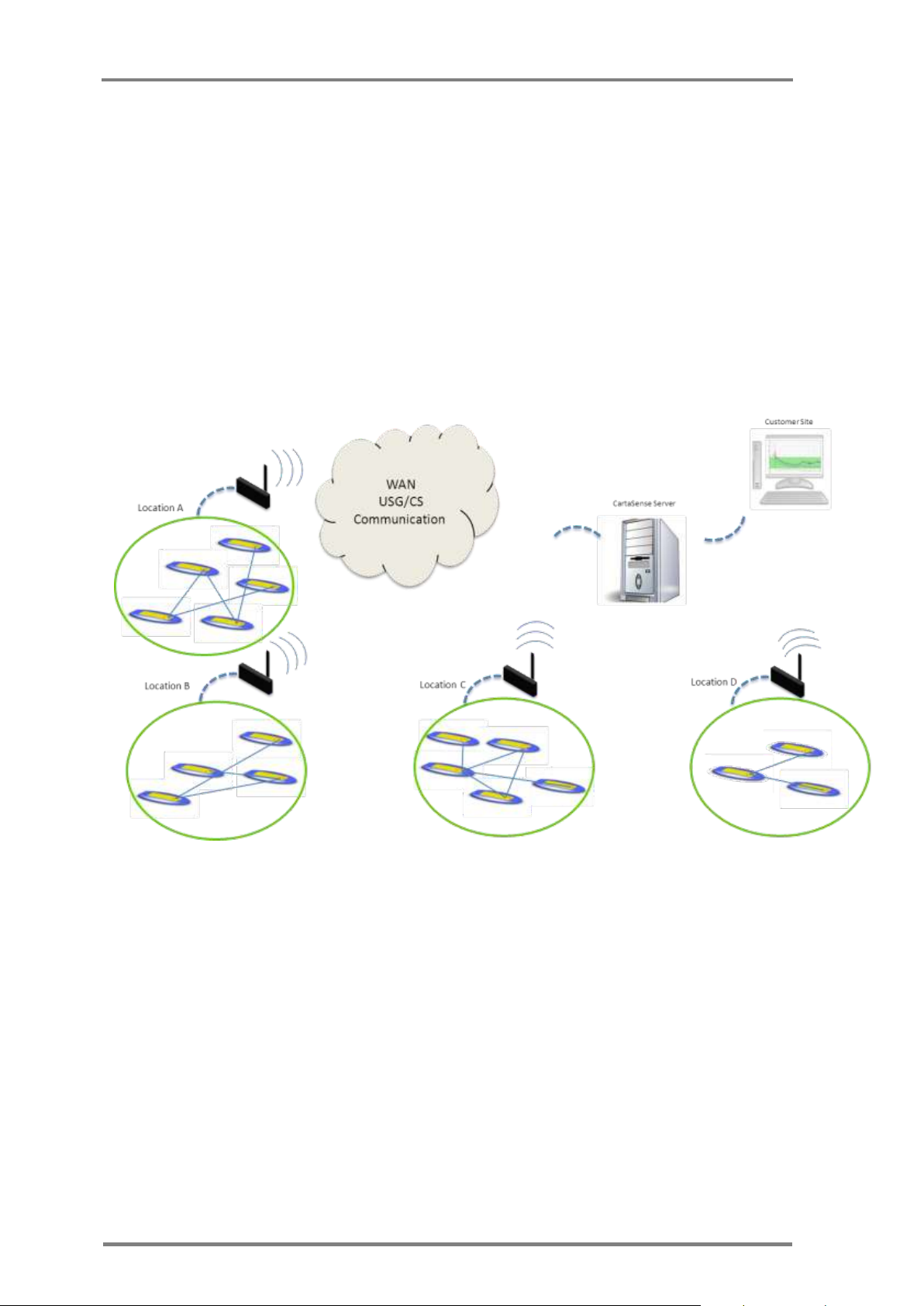
Once a USG is identified to be in communication range, data is transmitted
from the sensor to the gateway. Each USG is connected to the
Communication Server (CS) either through LAN (Ethernet gateway) or
cellular communication (GPRS Gateway), routing the received data from
all sensors..
Each one of CartaSense wireless sensors has the capability to operate as a
repeater to other Wireless sensors that are not in communication range
with the Gateway. All the sensors automatically form a dynamic, selfhealing, mesh network which is very resilient even when operating in
harsh electromagnetic environments.
1.3 Web application
A Web application provides online access to the data collected from all
around the monitored sites and faciltates real time monitoring and
observation of temperature and relative humidity conditions down to the
single package or pallet.
The application may be accessed from anywhere and enables the operator
to perform the following functions:
Figure 1: Typical system architecture
o View measurements from individual sensors or clusters of sensors.
o View status of sensors and/or USGs.
o Monitor Sensors network structure and performance.

System Description
Installation, Operation & Maintenance of the Wireless Sensing Family
3
o Provide reports at various levels of system operation.
o Generate alarms when preset threshold conditions are exceeded.
A Web Application manual that provides a detailed description of the
application and all its features is available under separate cover.
U-Sensors (US)
4
Version; 1.3
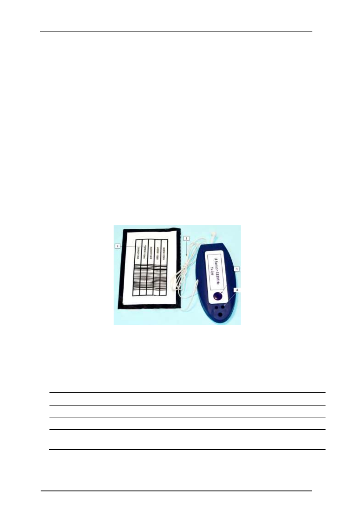
Item
Description
1
Antenna
For wireless communication
2
Barcode Sticker
U-Sensor unique identification
3
Power button
U-sensor activation and visual indication enable
4
Red LED
Active/not active, connected/not connected visual
indicator
2 Product description
2.1 U-Sensors (US)
The U-sensor (US) is a portable and disposable temperature and relative
humidity (RH) sensor.
The US is designed to be placed inside or near the monitored goods and
transmits measurements of the temperature and humidity at that location.
See Figure 2 for US unit, for detailed specification see Appendix A.3: below
The US sensor should be placed in each pallet to monitor product through the
overall supply chain.
The US periodically measures temperature and relative humidity. When
connection is available to a U-Sensor Gateway, either directly or indirectly
through another sensor, the measurements are uploaded to the
communication server. When such connection is not available, measurements
are stored in a non volatile memory and will be uploaded once wireless
connection is re-established. See 3.3.7 for setup and installation.
2.1.1 Operating the U-Sensor
Table 1: U-Sensor elements
Figure 2: U sensor

Product description
Installation, Operation & Maintenance of the Wireless Sensing Family
5
LED Indicator
Description
1 sec single blink
Activation visual feedback. Pressing the pushbutton for three
seconds, while the US is not active, will cause the U-sensor to
go active and to make a single blink of one second
Flashing red
Network connectivity indication. Pressing the pushbutton for at
least one second, will cause the LED indicator to show the
connectivity sate of the US. A one second repetitive blink
means the US is not part of a sensor network and
measurements are logged in the sensor's memory
Constant red
Network connectivity indication. Pressing the pushbutton for at
least one second, will cause the LED indicator to show the
connectivity sate of the US. A constant on LED light means the
US is part of a sensor network and measurements are delivered
to the U-sensor gateway
Pressing the pushbutton of an active U-sensor, the red light indicator should
light up in 1 sec (either continuously or blinking). If it does not light up, the
U-sensor has not been activated
2.1.1.1 Activation of the US
The US unit is powered up by pressing the power button for 3
seconds.
2.1.2 U-Sensor LED Indications
The US contains one red LED indicator. The LED indicator is normally off in
regular operation. To make it active, and see the US state, the pushbutton
has to be pressed. There are two distinct patterns to indicate the status of
the US, as listed in Table 2.
Table 2: U-Sensor indicator states, after pressing the pushbutton
2.2 M-Sensor (Air)
M-Sensors are targeted for outdoor applications such as metering, agriculture
and for integration with external sensors. The basic unit includes internal
temperature and RH sensors and has an option for an additional module with
extended RH capabilities. See Appendix A.4: for detailed specification.

M-Sensor (Air)
6
Version; 1.3
Item
Description
1
Power button
M-sensor activation and visual indication enable
2
LED indicator
Active/not active, connected/not connected visual indicator
2.2.1 Deployment of the M-Sensor (Air)
Figure 3: M-Sensor, Air – front & rear view
2.2.1.1 Assembly of the M-Sensor (Air)
Installing batteries: Unscrew the rear cover of the batteries
compartment (3) and install 2 AAA batteries. Make sure to keep
polarity of battery as indicated in the compartment.
2.2.1.2 Activation of the M-Sensor (Air)
M-Sensor is activated by a pressing the push button for 3 seconds
The M-sensor gives a positive visual indication of the success of the
activation process.
Table 3: M-sensor elements
2.2.1.3 Operation of the M-Sensor (Air)
The M-sensor, once active, connects to an available CartaSense sensors
network.

Product description
Installation, Operation & Maintenance of the Wireless Sensing Family
7
2.3 M-Sensor Soil
The soil sensor has external soil moisture sensor probe and soil temperature
probe, enabling precise monitoring of soil water content and temperature.
The M-Sensor soil is used for tracking soil moisture and temperature trends
in crops, vineyards, or other areas where moisture level is a concern.
See Appendix A.5: for detailed specification.
2.3.1 Deployment of the Soil Sensor
Figure 4: A-sensor soil
2.3.1.1 Assembly of the Soil-Sensor
Assembly of the M-Sensor soil is similar to the assembly of the M-sensor Air.
Refer to paragraph 2.2.1.1.
2.3.1.2 Activation of the Soil -Sensor
M-Sensor is activated by pressing the push button for 3 seconds
The M-sensor gives a positive visual indication of the success of the
activation process as described in Table 3
2.3.1.3 Operation of the Soil Sensor
The M-sensor, once active, connects to an available CartaSense sensors
network.
2.4 M-Sensor Sun
The Sun sensor is based on the M-Sensor and has external sun radiation PPF
sensor. The unit contains internal temperature sensors and optionally RH
sensors - see Appendix A.6: for detailed specification.

Resident Sensor (RS)
8
Version; 1.3
Figure 5: M-Sensor Sun
2.4.1 Deployment of the M-Sensor Sun (A-Sensor Sun)
2.4.1.1 Assembly of the Sun-Sensor
Assembly is same as defined in 2.2.1.1
2.4.1.2 Activation of the Sun -Sensor
Activation is same as defined in 2.2.1.2
2.4.1.3 Operation of the Sun Sensor
The M-sensor, once active, connects to an available CartaSense sensors
network.
2.5 Resident Sensor (RS)
The RS is a stationary wireless sensor that monitors temperature and RH
environmental conditions and also serves as a range extender / repeater for
other sensors in its vicinity. See Appendix A.2: for detailed specification.
Figure 6 & Figure 7 depict the RS from top, side and bottom views and
Table 4 defined RS controls & indicators.
1

Product description
Installation, Operation & Maintenance of the Wireless Sensing Family
9
Label
Name
Description
1
Resident Sensor ID
Unique ID of the Resident Sensor
2
Red LED Indicator
Indication for resident Sensor status
3
Sticker
Resident Sensor removable sticker
4
Antenna
Resident Sensor antenna
5
Batteries compartment
Holds 2 AAA batteries
6
Push Button
A countersunk operation button which is operated with a pin
Figure 6: Resident Sensor top & side view
Figure 7: Resident Sensor - bottom view
Table 4: Resident sensor elements
2.5.1 Deployment of the Resident Sensor
2.5.1.1 R-Sensor Assembly
Unpack the RS unit.
Open up the Batteries compartment cover (5)
Insert two AAA batteries.
Make sure to keep batteries polarity as displayed in the
compartment.
Make sure that there is good contact of both battery poles
Replace the Batteries compartment cover.

U-Sensor Gateway
10
Version; 1.3
LED Indicator
Description
1 sec single blink
Activation visual feedback. Pressing the internal pushbutton for three
seconds (use a pin), while the R-Sensor is not active, will cause the Rsensor to go active and to display a single blink of one second
Flashing red
Network connectivity indication: Pressing the pushbutton for at least
one second, will cause the LED indicator to show the connectivity sate
of the R-Sensor. A one second repetitive blink means the R-Sensor is
NOT part of a sensor network and measurements are logged in the
sensor's memory
Constant red
Network connectivity indication: Pressing the pushbutton, for at least
one second, will cause the LED indicator to show the connectivity sate
of the R-Sensor. A constant on LED light means the R-sensor is part of
a sensor network and measurements are delivered to the U-sensor
gateway
2.5.1.2 RS activation and visual indications
Turn on the RS unit by pressing the on/off pushbutton (6) using a pin
(paper clip or similar).
The RS has one red LED indicator that can be seen from the two viewing
/ vent holes on the side and back panel (marked as element #2). This
indicator blinks as defined in Table 5:
Table 5: RS LED indications
2.6 U-Sensor Gateway
The U-Sensor Gateway is designed to transmit all the data collected by
CartaSense sensors throughout the monitored site to the communication
server and through it – to the Web application.
The USG acts as an access point for U-sensors, R-Sensors, M-sensors and
other CartaSense wireless sensors. The USG is the "root node" of the sensors
network, where all measurements are uploaded to. The USG also connects to
the communication server, further uploading measurements from the sensors
through an internet connection, whether cellular or LAN based.
Several versions of USGs are available. – The USGs differ in their system
interface and include the following:
Cellular GPRS interface.
GPRS cellular with GPS location module.
Dashboard mounted GPS/GPRS unit
Ethernet 10/100 MB interface
For detailed USG specifications – see Appendix A.1:
 Loading...