

Page 1
AG501: Unboxing & setup
Page 1 of 8
AG501
System shipped lying
Revision: 1
Approved
on: February 19th, 2015
on:
by: Ulrich Szagun
by:
I. Quickstart Guide
The AG501 can be set up and running within minutes. Just follow these steps to get going.
A description with all steps covered in detail can be found following this chapter.
Remove the cardboard packaging and padding material (Chapter II).
Attach the wheels of the AG501 (Chapter III-A).
Remove the AG501 from the palett (III-B).
Arrest the arm of the AG501 (Chapter III-C).
Connect the cables of the AG501 (Chapter IV).
Start the Control Server and log in as user csop (see Chapter V-A for password).
Open the AG501 user guide to learn about calibration and measuring (Chapter V-B).
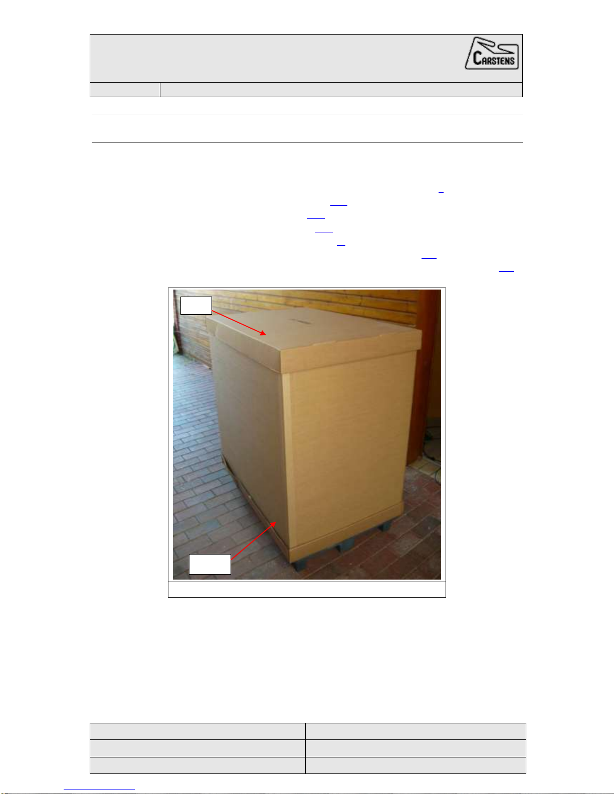
Figure 1: The cardboard packaging of the AG501
Lid
Ring
Page 2

AG501: Unboxing & setup (system shipped lying)
Page 2 of 8
Revision 1
February 19th, 2015
II. Unboxing of the AG501
The AG501 is shipped in a cardboard packaging strapped to a pallet.
Remove the straps and protective foil carefully from the cardboard packaging.
Subsequently the lid and ring of the cardboard (Figure 1) can be removed easily by
pulling them upward.
After taking off the upper part of the packaging you will find the AG501 fixed to the pallet
together with its accessories in a cardboard box (Figure 2). The exposed parts are
additionally protected by padding material.
Carefully remove the padding material from the system.
Please note, that the screws and sockets for fixing the arm (Figure 12) of the AG501 are
taped to the the arm underneath the padding material. Please do not accidentally dispose
them together with the padding material.
Open the package containing the system equipment and empty it completely.
The package is fixed to the palett, so it has to be emptied in place. However, it is
important to remove all parts from the package before continuing.
Attach the wheels to the AG501 (Chapter III-A).
Figure 2: The AG501 strapped to the transport palett
Package with equipment
Page 3
AG501: Unboxing & setup (system shipped lying)
Page 3 of 8
Revision 1
February 19th, 2015
III. Setting up the AG501
A. Attaching the wheels
To attach the wheels the AG501 should remain mounted to the palett.
The wheels (Figure 3) with the required screws are in the cardboard box of accessories, where
you can also find the Allen wrench to tighten the wheels (Figure 4).
Attach front wheels and back wheels as described in III-A-1 and III-A-2.
Arrest the back wheels and carefully bring the AG501 to the upright position.
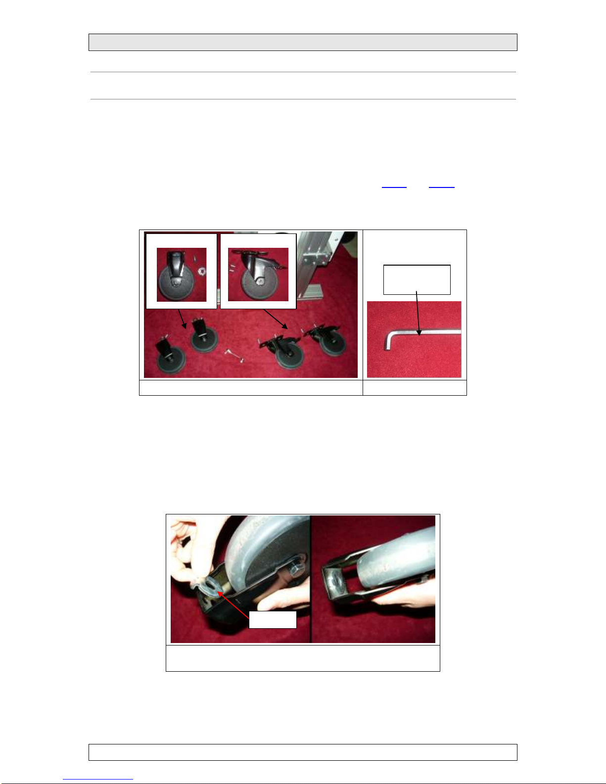
Figure 3: The wheels of the AG501
Figure 4: Allen wrench
1. Front wheels
Place the washer inside the mounting of the front wheels (Figure 5).
Insert the washer pins in the outer holes.
Screw on the front wheel to the T-slot nut with the Allen wrench (Figure 6).
Align the mounting of the wheel with the front of the frame by moving the T-slot nut
correspondingly before finally tightening the screw.
Figure 5: Place the washer in the outer holes leaving the central
hole open for the screw
Washer
Front wheels
Back wheels
5mm Allen
wrench
Page 4

AG501: Unboxing & setup (system shipped lying)
Page 4 of 8
Revision 1
February 19th, 2015
Figure 6: The mounting of the wheels should be aligned with the front of the frame
2. Back wheels
Move the T-slot nuts to the back of the frame and adjust the distance between them
so that they match the holes of the back wheel mounting (Figure 7).
Screw on the back wheel to the T-slot nuts with the Allen wrench (Figure 7).
Align the mounting of the wheel with the back of the frame by moving the T-slot nuts
correspondingly before finally tightening the screw.
Figure 7: Fix the back wheel to the T-slot nuts
Wheel mounting
Frame
T-slot nut for the front wheel
T-slot nuts for back wheel
Page 5

AG501: Unboxing & setup (system shipped lying)
Page 5 of 8
Revision 1
February 19th, 2015
B. Removing the AG501 from the palett
Before continuing make sure you removed all loose parts from the palett and that the package
with the system equipment is empty.
Lock the back wheels of the system.
Bring the AG501 to an upright position by tipping over the palett carefully, so that
the AG501 stands on its wheels (Figure 8).
Remove the flat-head screws that attach the system to the palett with the Allen
wrench (Figure 8) and take off the palett.
Loosen the screws of the transport sections and remove the T-slot nuts (Figure 9).
Put the filling material in the profile of the removed T-slot nuts (Figure 10).
Figure 8: Bring the AG 501 to an upright position and loosen the flat-head screws
to remove the palett from the system.
Figure 9: Loosen the screws of the transport sections and remove the T-slot nuts
Figure 10: Put the filling material in the profile of the removed T-slot nuts
Flat-head screws
T-slot nut
Transport section
T-slot nut
Page 6

AG501: Unboxing & setup (system shipped lying)
Page 6 of 8
Revision 1
February 19th, 2015
C. Arresting the arm
Move up the housing of the AG501, so the arm can swing freely (Figure 11).
Bring the arm to the horizontal position and apply the inserts to the inner and outer
holes (Figure 13). The screws and inserts for arresting the arm are taped to the outside
of the arm (Figure 12).
Secure the inserts with the screws (Figure 13).
Figure 11: To adjust the height of the AG501 loosen the lever
and move the housing up or down.
Figure 12: The screws for arresting the arm are taped to the arm
Figure 13: Bring the arm to the horizontal position and apply
one insert to the inner hole and one to the outer hole.
Screws and inserts
Lever for height adjustment
Page 7

AG501: Unboxing & setup (system shipped lying)
Page 7 of 8
Revision 1
February 19th, 2015
IV. Connecting the AG501
A. E-Box and Control Server
Connect the yellow LAN cable between E-Box and Controls Server (Figure 14).
Connect the power connector and the grounding cable as seen in Figure 14.
If you need access to your local network, you can insert the provided LAN express card into the
Control Server (Figure 14) and connect it via LAN-connector.
For Control Server configuration please see Adding the control server to a local network in the
AG501 User Guide (501-user-guide.pdf).
Figure 14: E-Box and Control Server cable connections
B. Sybox
Drag the Sybox cable out of the housing‘s bottom opening (one end is permanently
affixed within the housing) and connect it to the Sybox (Figure 15).
Set up the components for sound recording according to the manual (AG501_sound.pdf).
Figure 15: The Sybox connection cable is located inside the
housing of the AG501
Yellow LAN cable
Grounding cable
Power connector
LAN Express card
Sybox connection cable
Page 8

AG501: Unboxing & setup (system shipped lying)
Page 8 of 8
Revision 1
February 19th, 2015
V. Starting the Control Server
A. Logging in
When starting the Control Server a login-screen welcomes you (Figure 16-1).
Choose csop as user by clicking on the name (Figure 16-1).
Type in the password for the csop-user (Figure 16-2).
The password for csop is always the name of the Control Server (Figure 16). So if the
name of your Control Server is cs61 then the password for csop is cs61.
Figure 16: Logging into the Control Server. The password for csop is the
name of the Control Server.
B. Opening the User Guide
To open the AG501 user guide click on Applications in the upper left corner of the
screen (Figure 17-1), choose AG501 and click on AG501 user guide in the sub-
menu (Figure 17-2).
The AG501 User Guide is a collection of pdf-documents, where you can find all the
necessary information for operating and maintaining the AG501 system with its
peripherals. Depending on your previous knowledge the main manual is a good starting
point, from where to explore the possibilities of the AG501.
Figure 17: Opening the AG501 user guide
VI. Revision history - AG501: Unboxing & setup
Date
Revision
Annotation
February 19th, 2015
1
Ulrich Szagun
Click here
1
2
Type password
Control Server name
Click here
1 2 User guide
 Loading...