

Page 1

INSTALLATION INSTRUCTIONS
50-0212x-002 SERIES 1181281
50-0212x-014 SERIES 1181280
OVERHEAD CONSOLE for use with FLIPDOWN VIDEO SYSTEM
These instructions are intended for use only by experienced professionals in the automotive
customizing business. Special tools and equipment, as well as specialized handling and care of
product during installation, may be required. Before beginning this installation, carefully read
through the following instructions. Use extreme care when cutting headliner material.
Check for wiring or other componentry above headliner material. Cut only where indicated.
Materials / Tools required for this installation:
1. Phillips screwdriver 2. Powered screwdriver or drill with adapter
3. Awl or scribe point tool or similar 4. Razor knife or similar tool
5. T-10TORX bit driver 6. 1/8" Drill Bit
7. Audiovox Series 640/650 Video Module
FOR USE IN VEHICLES WITH FACTORY INSTALLED
OVERHEAD CONSOLE ONLY.
Materials provided for this installation:
FOR
FORD EXPEDITION
INSTALLATION INSTRUCTION # 44-0018D
Apr. 14, 1999
Page 2

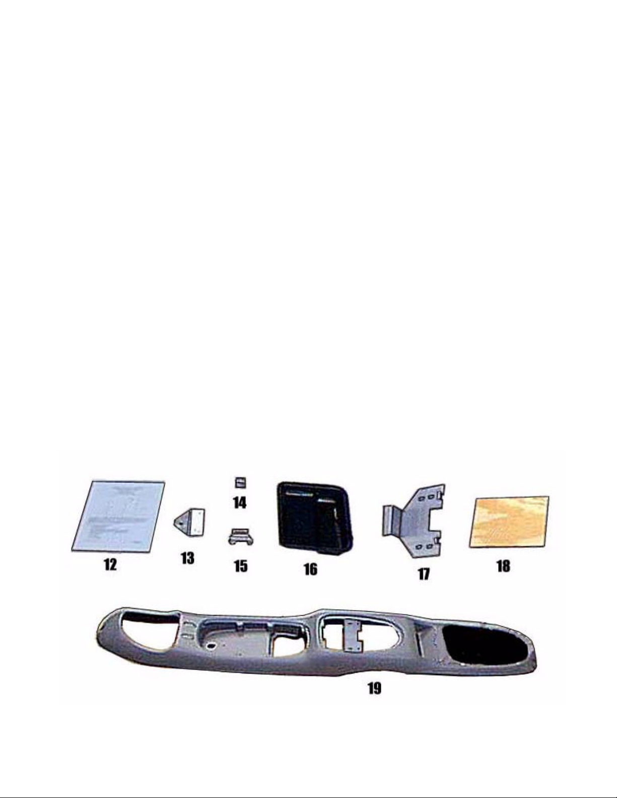
ITEM DESCRIPTION QTY
1 Nut, 6-32 HH KEPS 8
2 Screw, # 6 x 3/8 PPH TAB 13
3 Screw, # 8 x 9/16 PWH TAB 2
4 Screw, 6-32 x 1/2 PPH 4
5 Screw, 6-32 x 3/4 PPH 10
6 Screw, # 8 x 1 1/4 PWH TAB 2
7 Screw, # 8 x 1 1/2 PWH TAB 1
8 Screw, # 8 x 1 3/4 POH TAB Z1 2
9 Washer, 3.5 mm 4
10 Finish Washer, # 8 2
11 Convoluted Tube, 1/2" ID X 3" 1
12 Template (last page of
1
instructions)
13 Front Mounting Bracket 1
14 Pod Mounting Bracket 4
15 Switch Mounting Bracket 2
16 Rear Air Duct Blockoff Plate 1
17 Rear Mounting Bracket 1
18 Plywood , 3/8" x 7" x 8 1/2" 1
19 Overhead Console 1
INSTALLATION INSTRUCTION # 44-0018D Apr. 14, 1999
Printed in the U.S.A.
2
Page 3
3
Page 4
I. REMOVAL OF O.E.M. EQUIPMENT.
1. Remove and retain OEM overhead console assembly by removing one (1) OEM screw in front pocket. Pull
console down and disconnect wiring. Set aside in a safe place for later re-installation.
2. Remove and retain rear A/C control assembly. Assembly housing is secured with two (2) spring loaded
fasteners on front of housing. Pull down to disengage, then slide forward to clear bracket. Disconnect
wiring. Set assembly aside in a safe place for re-use later.
3. Remove center A/C vent in headliner using two scribe points in indicator holes on vent and twist.
II. PREPARATION OF VEHICLE.
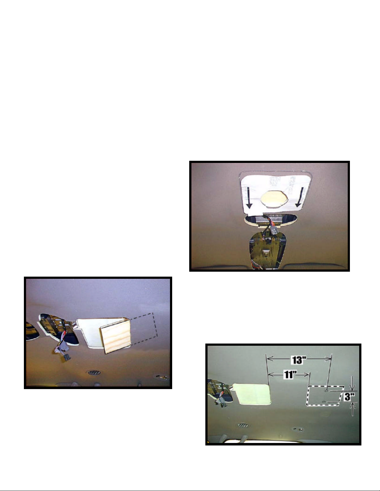
1. Place template provided (item 12 pg 2) over center
A/C vent hole with arrow pointing forward. Cut
and remove indicated headliner. See Figure 1.
Figure 1
2. Install plywood block (item 18 pg 2) provided in kit
through modified louver opening and secure in place
using two (2) # 8 x 9/16" PWH screws (item 3 pg2).
See Figure 2 and 3.
Figure 2
Figure 3
4
Page 5

Figure 4
4. Detach wire harness from brace where A/C assembly
was removed. Remove and retain two (2) OEM
screws. Trim headliner to clear front flange of rear
mounting bracket (item 17 pg 2) Insert rear mounting
bracket tabs in existing slots on rear of OEM brace.
Align holes of bracket with OEM bracket. Secure
with OEM screws. See Figure 5. Route wiring
toward driver’s side of bracket. Install convoluted
tube (item 11 pg 2) around wire harness to prevent
chaffing against bracket.
3. Install block-off cover (item 16 pg 2) using one (1)
# 8 x 1 1/4" PWH screw (item 6 pg 2). See Fig. 4.
(Use caution to assure screw does not penetrate
vehicle roof ).
Figure 5
5. Remove and retain two (2) OEM screws located
at front of OEM bracket near windshield. Mount
front bracket (item 13 pg 2) using OEM holes and
OEM screws. See Figure 6.
Figure 6
5
Page 6

6. Install video system wiring into vehicle. Route video
system cables from installed position in center of roof to
“B”-pillar. Down “B”-pillar to floor. Route power and
ground leads forward to fuse box area. Connect power wire
to a fused accessory controlled power source per
instructions provided in video system. Ground negative lead
to chassis. Route remaining wiring (RCA plugs, Remote
sensor extension, etc.) to VCP location. Connect per
instructions provided with video system. If video system is
to be used as a television, install an appropriate antenna per
instructions included with antenna. See Figure 7.
III. PREPARATION OF OVERHEAD CONSOLE.
1. Remove and retain OEM front control head bezel
assembly by removing four ( 4 ) screws. See Fig. 8.
Figure 8
2. Remove and retain secondary light and pod assembly by
removing eight ( 8 ) OEM screws. See Figure 9.
Figure 7
Figure 9
6
Page 7

Figure 11
3. Attach four (4 ) pod mounting brackets (item 14 pg
2) to front and rear of bezel with four (4 ) 6-32 X
1/2" screws (item 4 pg 2) and four (4) 8-32 KEPS
nuts (item 1 pg 2). See Figure 10.
Figure 10
4. Install and secure O.E. bezel in overhead
console (item 19 pg 2) with eight ( 8 ) # 6
X 3/8" PPH screws (item 2 pg 2) As
shown. See Figure 11.
7
Page 8

Figure 12
6. Install and secure secondary light pod assembly in
overhead console with six ( 6 ) OEM screws. See
Figure13. Note: Be sure light wiring is
accessible.
5. Remove two (2) plastic tabs on secondary
light and pod assembly, replace two ( 2 )
OEM screws in front assembly as shown.
See Figure 12.
Figure 13
8
Page 9

7. Remove A/C control from rear bezel assembly. Modify A/C control by drilling three (3) 1/8" dia. holes
in front mounting tabs. Position rear A/C control head in center of overhead opening. Secure with five
(5) # 6 X 3/8" PPH screws (item 2 pg 2). See Figure 14.
Figure 14
8. If vehicle is equipped with OEM vent switches,
remove and discard blank plug in new overhead console.
Retain four (4) screws. Remove and discard four ( 4 )
Figure 16
screws from OEM console. Remove and modify switch
assembly by trimming four ( 4 ) tabs flush with edge.
Install two ( 2 ) mounting brackets (item 15 pg 2 ) using
four ( 4 ) 6-32 X 3/4" screws (item 5 pg 2 ) and four (4)
keps nuts (item 1 pg 2). Install and secure OEM vent
switch assembly using four ( 4 ) screws previously
removed. See Figure 15.
Important: Be sure vent switch assembly is centered in
console openings. Manually push switch buttons to
check for proper clearance and function.
Figure 15
IV. INSTALLATION OF OVERHEAD CONSOLE.
Caution: Do not overtighten screws. Use extra support for the console until secured to the vehicle.
Failure to do so may cause damage to console or installed components.
9
Page 10

3. Secure front of console using one ( 1 ) # 8 X 1 1/2"
PWH screw (item 7) in front pocket of OEM
secondary pod and light assembly. See Figure 17.
4. Install one ( 1 ) # 6 x 1 1/4" PWH screw (item 6
pg 2) in dimple area at front of console through
front mounting bracket. See Fig. 17.
5. Tighten 6-32 X 3/4" screws previously installed
in step 2.
1. Raise overhead console into
approximate position and connect
wiring to components.
2. Loosely fit console against headliner.
Check that console is centered in
vehicle and matches all contours of
headliner. While supporting console
in mounting position, loosely install
using two (2) 6-32 X 3/4" screws
(item 5 pg 2) through the smaller
holes in bracket on console into
threaded clips on mounting bracket.
Inspect wiring to make sure no
chaffing has occurred near the rear
bracket (Item 3).
Figure 17
Figure 19
10
Page 11

6. Release video screen from locked position. Lower video screen to viewing position for access to mounting
locations in top of video system housing.
7. Raise video system into approximate position and connect all wiring to components. Route video cable
through hole in mounting bracket. Connect wiring and cabling to video system per instructions included
with video system.
8. Check function of all components and lights. See operating instructions for video system operations check.
For further assistance, refer to the video system manual for the technical support phone number listed for
your area.
9. Insert video system into opening in console. Note: Make sure that wires do not get pinched
between bosses on video system and console. Align holes in housing with threaded clips in mounting
bracket. Loosely install four (4) 6-32 X 3/4" screws (item 5 pg 2) and four (4) 3.5 mm washers (item 9
pg 2). Caution: Do not overtighten screws. See Figure 18.
10. Raise video screen into locked position.
Figure 18
11. Install two (2 ) # 8 x 1 3/4" POH screws (item 8 pg 2) and two (2) # 8 finish washers (item 10 pg 2) in
dimples at rear of overhead console to secure rear of console to plywood support installed above
headliner. See Figure 19. Do not overtighten screws.
11
Page 12

CUT ON DOTTED LINES
12
 Loading...