

Page 1

Betriebsanleitung Seite 2 - 15
쮕
Instruction Manual Page 16 - 29
CARSON FY8 Brushless 50 040 9091
Page 2
Sehr geehrter Kunde
D
Wir beglückwünschen Sie zum Kauf Ihres CARSON RC-Modell autos,
das nach dem heutigen Stand der Technik gefertigt wurde.
Da wir stets um Weiterentwicklung und Verbesserung unserer
Produkte bemüht sind, behalten wir uns eine Änderung in technischer
Hinsicht und in Bezug auf Ausstattung, Materialien und Design jederzeit und ohne Ankündigung vor.
Aus geringfügigen Abweichungen des Ihnen vorliegenden Produktes
gegenüber Daten und Abbildungen dieser Anleitung können daher
keinerlei Ansprüche abgeleitet werden.
Diese Bedienungs- und Montageanleitung ist Bestandteil des
Produkts. Bei Nichtbeachtung der Bedienungsanleitung und der
enthaltenen Sicherheitsanweisungen erlischt der Garantieanspruch.
Bewahren Sie diese Anleitung zum Nachlesen und für die even tuelle
Weitergabe des Modells an Dritte auf.
Garantiebedingungen
Für dieses Produkt leistet CARSON eine Garantie von 24 Monaten
betreffend Fehler bei der Herstellung in Bezug auf Material und
Fertigung bei normalem Gebrauch ab dem Kauf beim autorisierten
Fachhändler. Im Falle eines Defekts während der Garantiezeit bringen
Sie das Modell zusammen mit dem Kaufbeleg zu Ihrem Fachhändler.
CARSON wird nach eigener Entscheidung, falls nicht anders im Gesetz
vorgesehen:
(a) Den Defekt durch Reparatur kostenlos in Bezug auf Material und
Arbeit beheben;
(b) Das Produkt durch ein gleichartiges oder im Aufbau ähnliches
ersetzen; oder
(c) Den Kaufpreis erstatten.
Alle ersetzten Teile und Produkte, für die Ersatz geleistet wird, werden
zum Eigentum von CARSON. Im Rahmen der Garantie leistungen
dürfen neue oder wiederaufbereitete Teile verwendet werden.
Auf reparierte oder ersetzte Teile gilt eine Garantie für die Restlaufzeit
der ursprünglichen Garantiefrist. Nach Ablauf der Garantiefrist vorgenommene Reparaturen oder gelieferte Ersatzteile werden in Rechnung
gestellt.
Von der Garantie ausgeschlossen sind:
• Beschädigung oder Ausfall durch Nichtbeachten der Sicherheitsanweisungen oder der Bedienungsanleitung, höhere Gewalt, Unfall,
fehlerhafte oder außergewöhnliche Beanspruchung, fehlerhafte
Handhabung, eigenmächtige Veränderungen, Blitzschlag oder
anderer Einfluss von Hochspannung oder Strom.
• Schäden, die durch den Verlust der Kontrolle über Ihr Fahrzeug
entstehen
• Reparaturen, die nicht durch einen autorisierten CARSON Service
durchgeführt wurden
• Verschleißteile wie etwa Sicherungen und Batterien
• Rein optische Beeinträchtigungen
• Transport-, Versand- oder Versicherungskosten
• Kosten für die Entsorgung des Produkts sowie Einrichten und vom
Service vorgenommene Einstell- und Wiedereinrichtungsarbeiten.
Durch diese Garantie erhalten Sie spezielle Rechte, darüber hinaus ist
auch eine von Land zu Land verschiedene Geltendmachung anderer
Ansprüche denkbar.
Konformitätserklärung
Hiermit erklärt Dickie-Tamiya GmbH & Co. KG, dass sich dieses Modell
einschließlich Fernsteueranlage in Übereinstimmung mit den grundlegenden Anforderungen folgender EG-Richtlinien: 98/37EG für
Maschinen und 89/336/EWG über die elektro magnetische Verträglichkeit und den anderen relevanten Vorschriften der Richtlinie 1999/5/EG
(R&TTE) befindet.
Die Original-Konformitätserklärung kann angefordert werden:
Dickie-Tamiya GmbH & Co. KG • Werkstraße 1 • D-90765 Fürth •
Germany
Bedeutung des Symbols auf dem Produkt, der
Verpackung oder Gebrauchsanleitung: Elektrogeräte sind
Wertstoffe und gehören am Ende der Laufzeit nicht in den
Hausmüll! Helfen Sie uns bei Umweltschutz und Recourcenschonung und geben Sie dieses Gerät bei den entsprechenden Rücknahmestellen ab. Fragen dazu beanwortet
Ihnen die für Abfallbeseitigung zuständige Organisation
oder Ihr Fachhändler.
Wir wünschen Ihnen viel Spaß mit Ihrem
CARSON Modellauto und jederzeit gute
Fahrt!
Vor dem Gebrauch Ihres neuen Modells lesen Sie bitte dieses Handbuch sorgfältig durch!
2
CARSON FY8 Brushless 50 040 9091
Page 3
Inhalt
g
D
Vorwort .........................................................................................................................2
Lieferumfang ...............................................................................................................3
Sicherheitsanweisungen ........................................................................................4
Optionales Zubehör .................................................................................................5
Für den Zusammenbau erforderliches Werkzeug .........................................6
a. Chassis .....................................................................................................................6
b. Abnehmen der Karosserie ...............................................................................7
c. Einbau der Antenne ...........................................................................................7
d. Laden des Fahrakkus ..........................................................................................8
e. Einbau des Fahrakkus ........................................................................................8
Lieferumfang
fan
f. Einschalten der RC-Anlage...............................................................................9
g. Technische Daten Motor und Regler......................................................... 10
h. Anschluss / Verkabelung ............................................................................... 10
i. Grundeinstellungen ........................................................................................ 11
j. Erklärung des Gashebelbereichs ................................................................13
k. Steuerung des Models.................................................................................... 14
l. Fehlersuchtabelle ............................................................................................15
Explosionszeichnung ............................................................................................ 30
Ersatzteile .................................................................................................................. 34
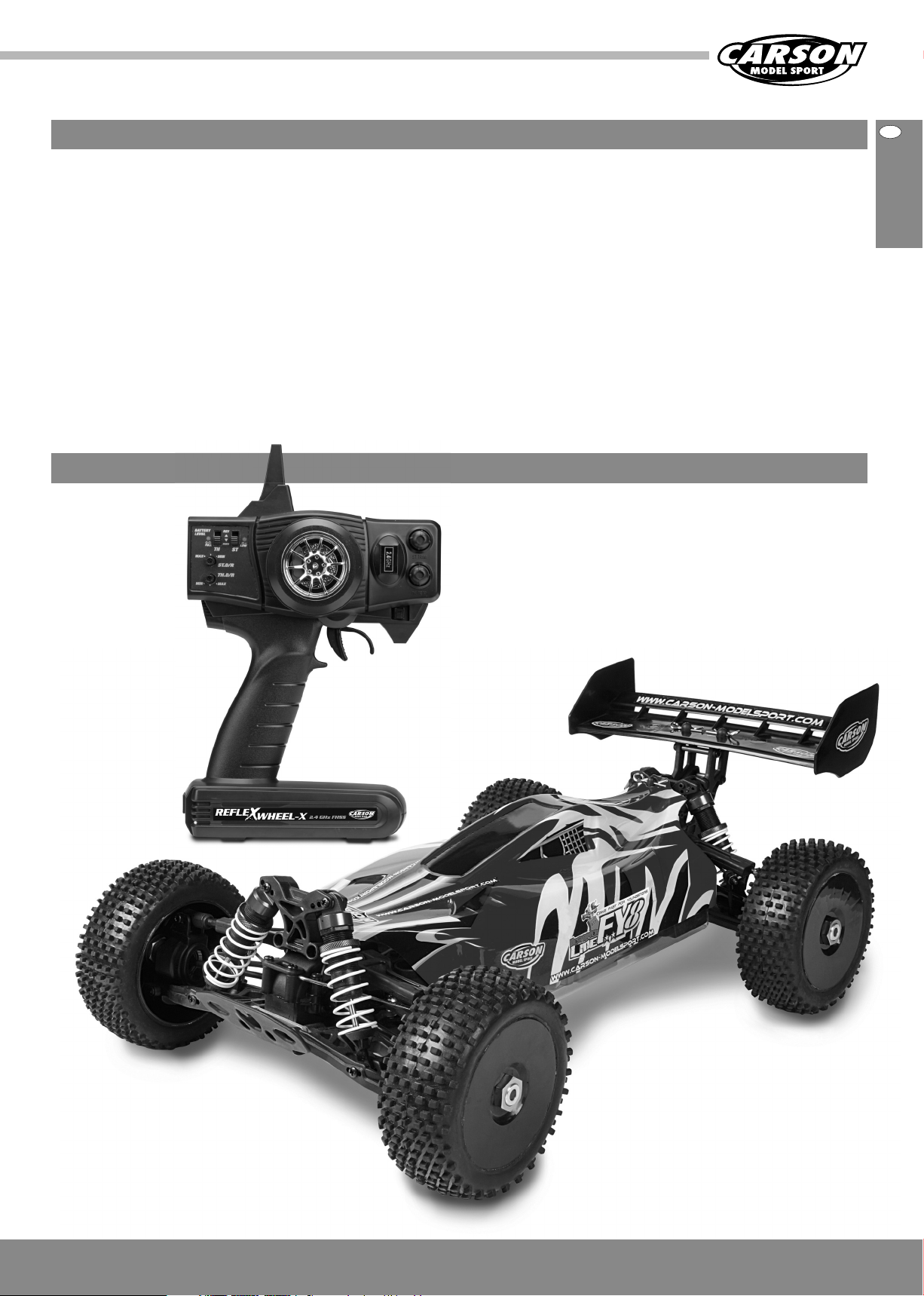
Sender
(nur bei RTR-Version)
Chassis mit Karosserie
3CARSON FY8 Brushless 50 040 9091
Page 4

D
Sicherheitsanweisungen
Funkferngesteuerte Modelle sind kein Spielzeug, ihre Bedienung muss schrittweise erlernt
werden.
• Kinder unter 14 Jahren sollten das Modell nur unter Aufsicht von
Erwachsenen in Betrieb nehmen.
Das Fahren von ferngesteuerten Modellautos ist ein faszinierendes
Hobby, das jedoch mit der nötigen Vorsicht und Rücksichtnahme
betrieben werden muss. Ein ferngesteuertes Modellauto kann in
einem unkontrollierten Fahrzustand erhebliche Beschädigungen und
Verletzungen verursachen, für die Sie als Betreiber haftbar sind.
Vergewissern Sie sich bei Ihrer Versicherung, ob Sie beim Ausüben
Ihres Hobbys versichert sind.
Nur ein einwandfrei zusammengebautes Modell
wird erwartungsgemäß funktionieren und
reagieren.
Fahren Sie niemals, ohne sich von den
folgenden Punkten überzeugt zu haben:
• Fahrakku und Senderakku müssen vollständig geladen sein.
• Überprüfen Sie vor dem Start die Funkreichweite.
• Überprüfen Sie das ordnungsgemäße Ansprechen der Servos auf
die Steuersignale.
• Alle Funktionsteile des Fahrzeugs sind in einwandfreiem Zustand
und überprüft.
Schalten Sie immer zuerst den Sender ein, um zu
vermeiden, dass der Empfänger unkontrolliert
auf ein fremdes Funksignal reagiert.
Bei gleichzeitigem Betrieb mehrerer Fahrzeuge darf das Modell nur auf
einer freien Frequenz betrieben werden.
Improvisieren Sie niemals mit untauglichen Hilfsmitteln, sondern
verwenden Sie im Bedarfsfall nur Originalersatzteile.
Auch bei einem vormontierten Modell sollten Sie alle Verbindungen
auf exakten und festen Sitz kontrollieren.
• Sämtliche Schrauben sind auf festen Sitz überprüft.
• Es ist kein RC- oder anderer Sender in der Nähe in Betrieb, der Funkstörungen verursachen könnte.
Störsignale auf gleicher Frequenz können bewirken, dass Sie die
Kontrolle über Ihr Modell verlieren.
Schalten Sie nach Beendigung des Fahrbetriebes zuerst den Empfänger, dann den Sender
aus.
• Fahren Sie auch nicht unter Hochspannungsleitungen oder Funkmasten oder bei Gewitter!
• Atmosphärische Störungen können die Signale Ihres Fernsteuersenders beeinflussen.
• Die Elektrik des Modells ist nicht wasserdicht. Fahren Sie deshalb
nicht bei Regen, Schnee,durch Pfützen oder nasses Gras.
• Das ferngesteuerte Modell darf nur auf geeignetem Gelände und
nicht auf öffentlichen Vekehrsflächen betrieben werden.
• Nicht in der Nähe von Personen und Tieren fahren!
• Fahren Sie nicht, wenn sie übermüdet oder anderweitig in Ihrer
Reaktionsfähigkeit beeinträchtigt sind.
• Halten Sie immer direkten Sichtkontakt zum Modell.
• Fahren sie das Modell nur mit ordnungsgemäß angebrachter
Karosserie.
4
CARSON FY8 Brushless 50 040 9091
• Das Modell hat Teile, die sich im Betrieb erhitzen, z. B. der Motor.
Die Berührung dieser Teile während des Betriebs kann zu
Verletzungen führen.
• Achten Sie auf Ladezustandsanzeige Ihres Senders.
• Mit halbleeren Akkus können sie die Kontrolle über das Modell
verlieren.
• Mischen Sie im Sender niemals volle Akkus / Batterien mit halbleeren oder Akkus unterschiedlicher Kapazität.
• Versuchen Sie nie, Trockenbatterien zu laden.
Bei längerem Nichtgebrauch ist der Fahrakku
unbedingt zu entfernen.
Page 5
Zum Schluss
pg
un
ktio
n
50 060 810
u
h
Bitte lesen Sie diese Betriebsanleitung sorgfältig durch, bevor Sie
irgendwelche Arbeiten beginnen.
Nach jeder Fahrt sollten Sie die wichtigsten Bauteile und Verbindungen überprüfen. Eine einzige gelockerte Schraube kann ausreichen, um Ihr Modell in eine gefährliche Situation geraten zu lassen!
Warten Sie Ihr Modell regelmäßig und wechseln Sie defekte oder
abgenutzte Bauteile gegen Original-Ersatzteile aus.
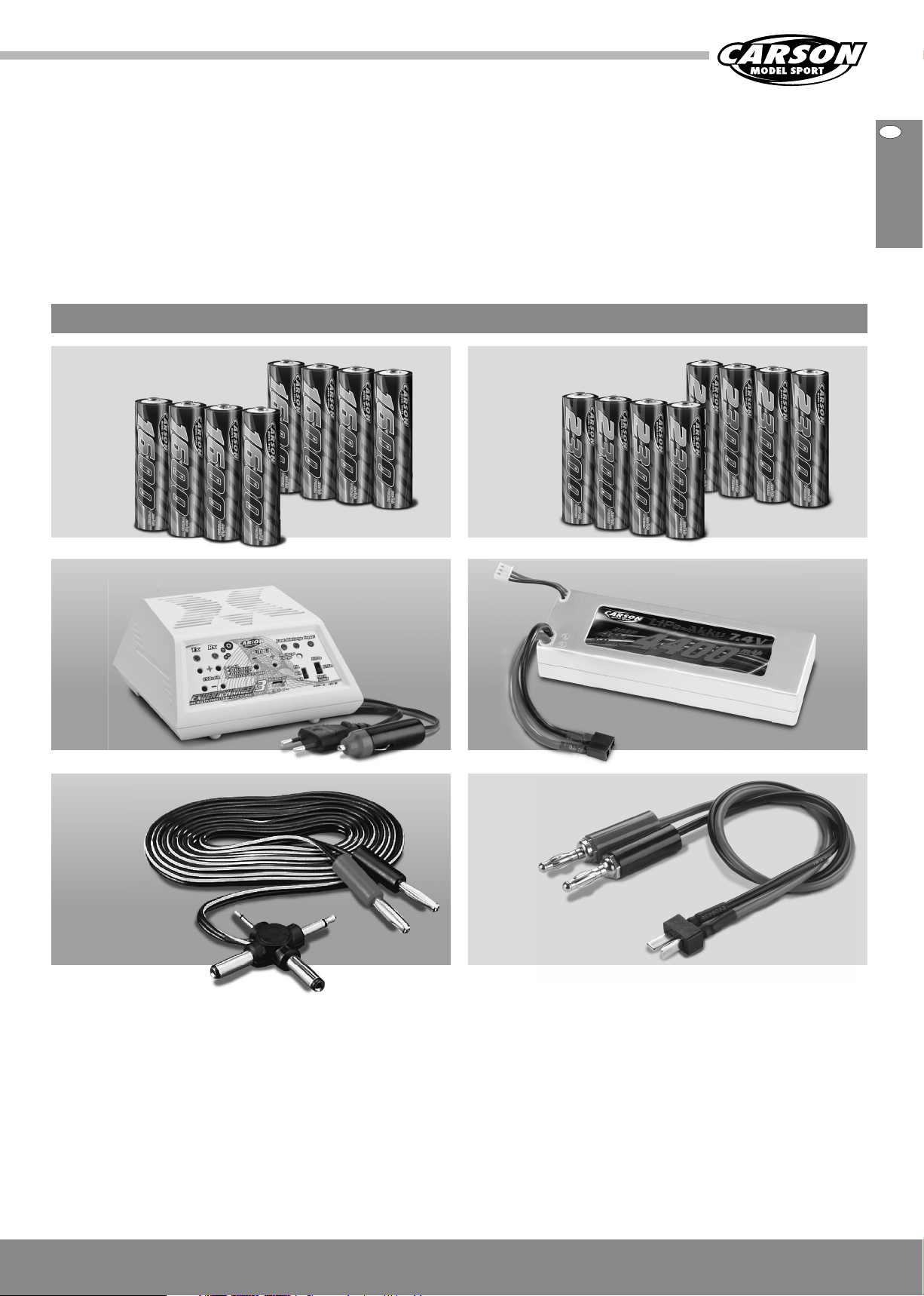
Optionales Zubehör
Wir wünschen Ihnen viel Spaß mit Ihrem
CARSON-Modellauto und jederzeit gute Fahrt!
D
Für den Sender: 50 060 9002 x2
8 Stück Mignonakkus 1600 mAh
50 060 6045 Expert Charger 3
mit LiPo-Funktion
50 001 3629 Ladekabel
für Sender
F
Für den Sender: 50 060 9000 x2
8 Stück Mignonakkus 2300 mAh
oder
50 090 6081 Ladekabel T-Plug
50 060 8101 LiPo Akku
7,4 V/ 4400 mAh
7,4 V/ 4400 mA
1 LiPo Akk
5CARSON FY8 Brushless 50 040 9091
Page 6
D
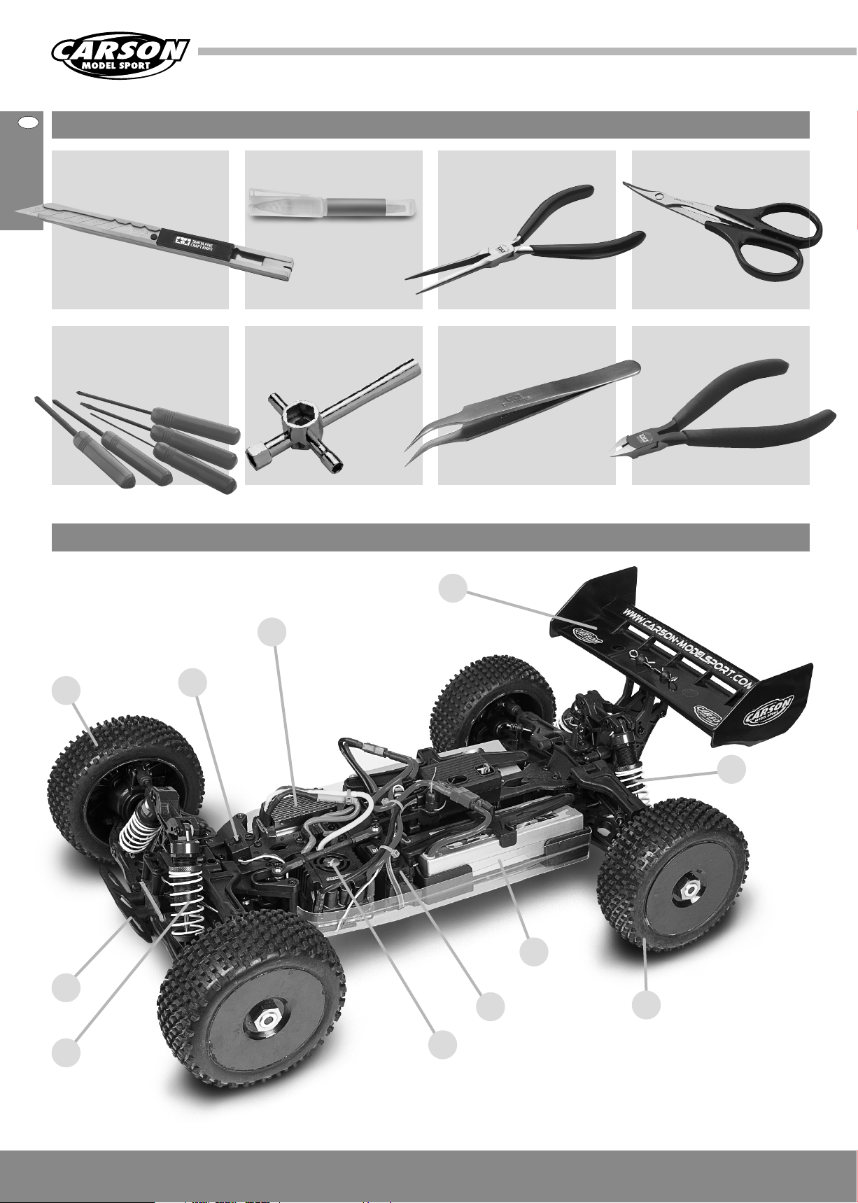
Für den Zusammenbau erforderliches Werkzeug
Modellbaumesser 30 007 4053
(klein und groß) und
Inbusschlüssel
1,5 / 2 / 2,5 mm 30 007 4023
a. Chassis
Sekundenkleber 30 005 3339
Kreuzschlüssel 50 090 5065Kreuzschlitz-Schraubendreher
Pinzette 30 007 4003
Schere 30 001 3305Spitzzange 30 007 4034
Seitenschneider 30 007 4035
Vorderreifen
Chassis
Ein-/Aus-Schalter
Motor
Spoiler
Lenkservo
Hinterer
Stoßdämpfer
Fahrakku
Hinterreifen
Vorderer Stoßdämpfer
6
CARSON FY8 Brushless 50 040 9091
Fahrregler mit Lüfter
Page 7
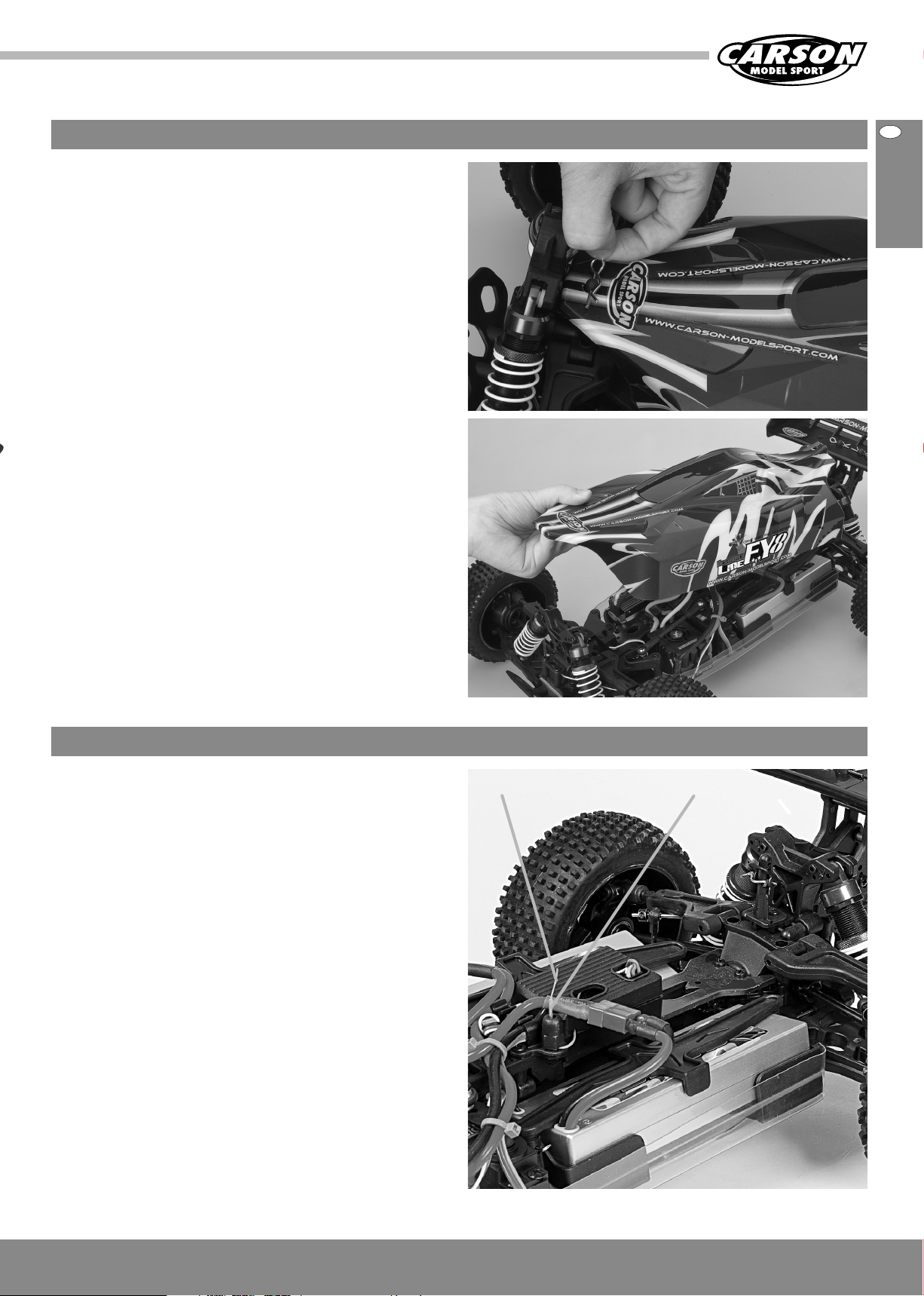
b. Abnehmen der Karosserie
• Ziehen Sie die Karosseriesplinte heraus und
• Nehmen Sie die Karosserie ab.
D
c. Einbau der Antenne
• Fädeln Sie den Antennendraht durch das Antennenrohr.
Antennendraht Antennenrohr
7CARSON FY8 Brushless 50 040 9091
Page 8
D
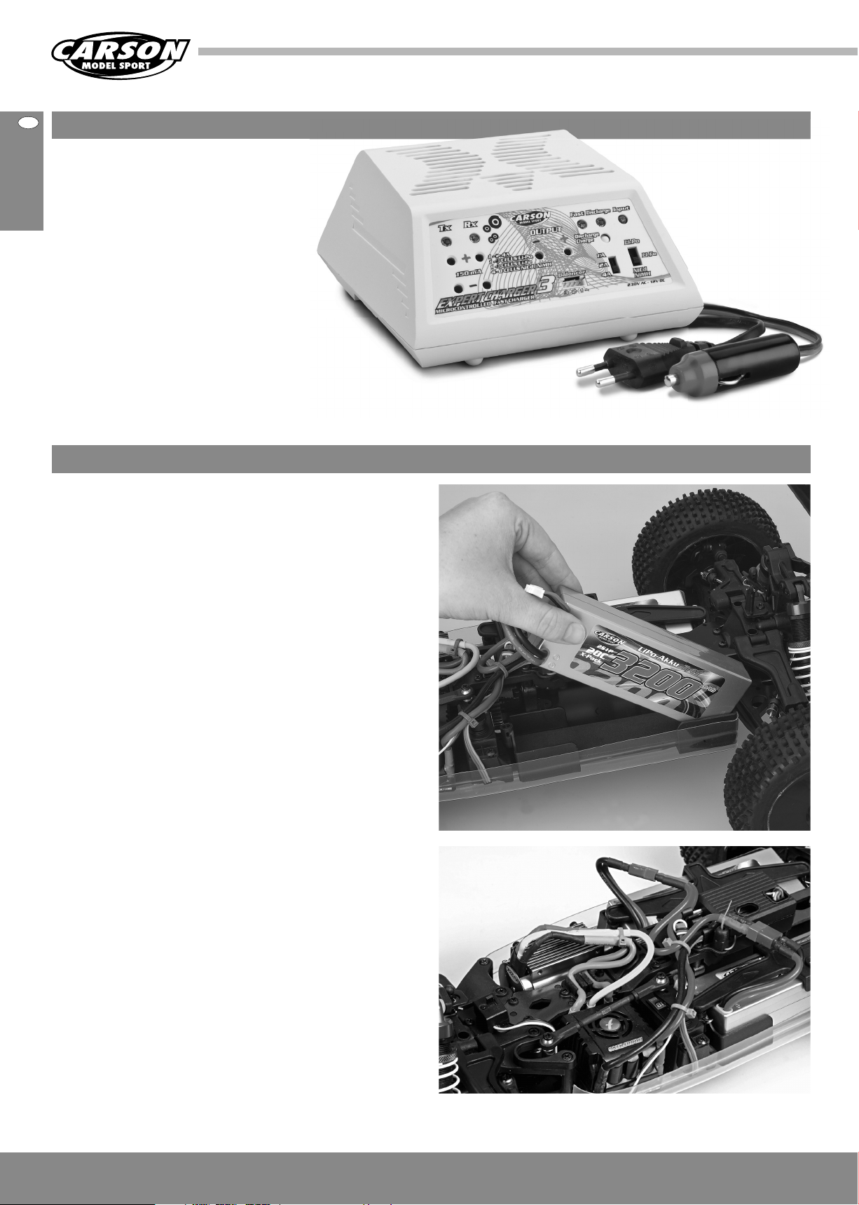
d. Laden des Fahrakkus
Achtung:
Verwenden Sie zum Laden der Fahr-Akkus nur
das empfohlene Ladegerät. Beachten Sie bitte die
Hinweise der Beiliegenden Anleitung.
e. Einbau des Fahrakkus
1 Legen Sie den Akku ein.
2 Setzen Sie die Abdeckung auf und
3 Fixieren Sie mit den Splinten.
Hinweis
• Wiederaufladbare Akkus müssen vor dem Aufladen aus dem Modell
genommen werden.
• Laden nur unter Aufsicht eines Erwachsenen.
• Beim einlegen der Akkus/Batterien auf die richtige Polarität achten.
• Leere Batterien/Akkus immer nach Gebrauch aus dem Modell entfernen.
• Die Anschlusskabel dürfen nicht kurzgeschlossen werden.
• Bitte überprüfen Sie regelmäßig die Elektronik oder Akkus, Ladegerät, Anschlussstecker, Kabel, Gehäuse und andere Teile auf Schäden.
8
CARSON FY8 Brushless 50 040 9091
Page 9
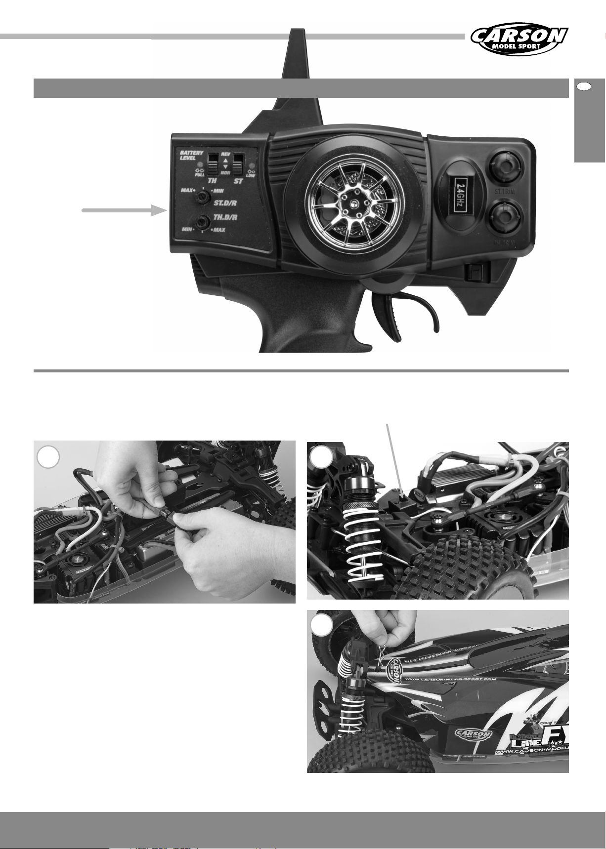
f. Einschalten der RC-Anlage
ACHTUNG!
Immer zuerst den
Sender einschalten!
ON
D
1 Schließen Sie den Fahrakku an.
2 Schalten Sie den Empfänger ein.
3 Setzen Sie die Karosserie auf und sichern Sie mit den Karosserie-
splinten.
1
on
2
3
9CARSON FY8 Brushless 50 040 9091
Page 10
g. Technische Daten Motor und Regler
Technische Daten Motor: Brushless
Motor Sensorlos
U/min 2230 UpV
U/min @ 14,8 V 33 000
Kurzzeitig 72 A
Abmessungen (A- Ø x L) 35,8 x 65 mm
Technische Daten Regler: Brushless
Vorwärts ja
Rückwärts ja
Eingangsspannung 2 - 4 LiPo Zellen/6 - 12 NimH Zellen
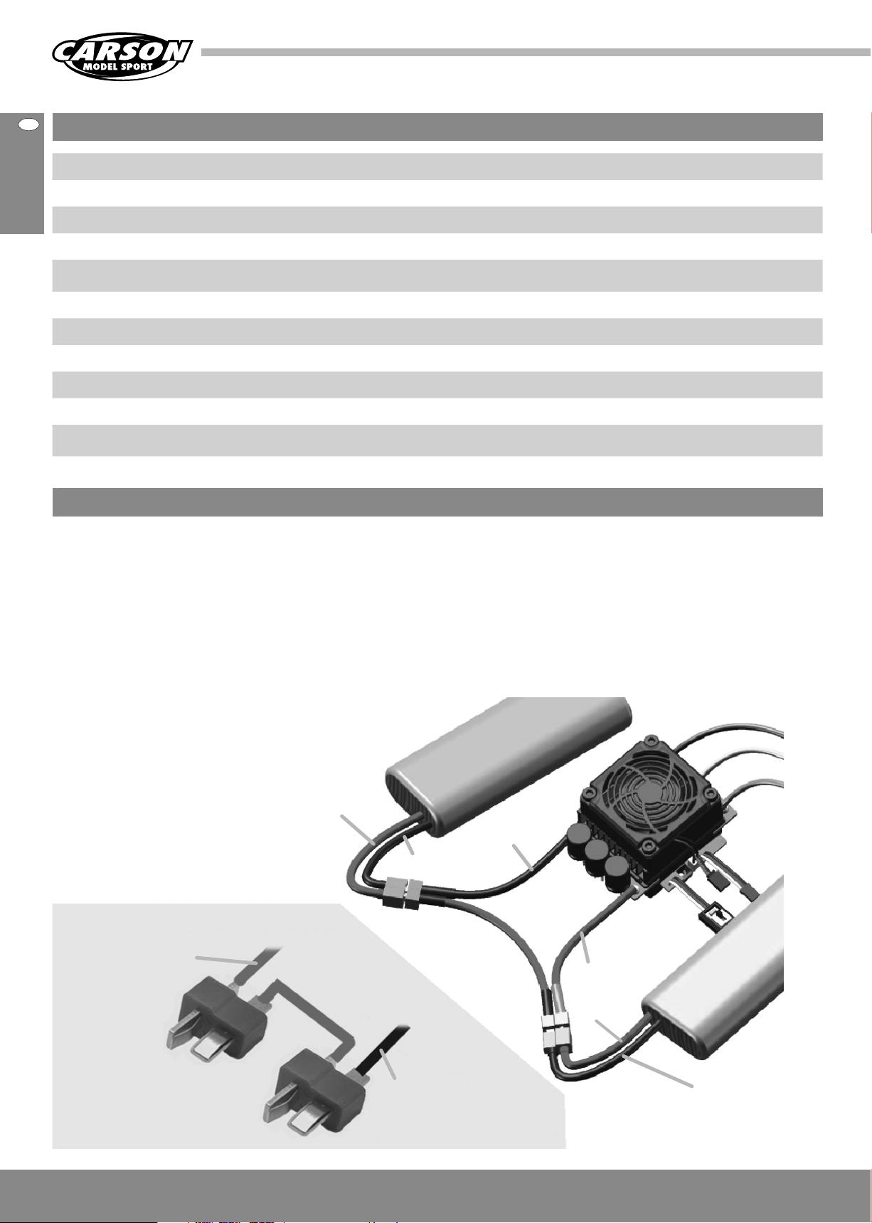
h. Anschluss/Verkabelung
Schließen Sie Fahrregler, Motor, Empfänger,
Akku und Servo gemäß der nachfolgenden
Skizze an.
Positive (+) und negative (-) Anschlüsse des Fahrreglers werden mit
dem Fahrakku verbunden.
A, B und C werden mit den Motorkabeln verbunden. Das Empfängerkabel des Fahrreglers (Kabel in schwarz, rot und weiß) wird mit dem
Gaskanal des Empfängers verbunden (normalerweise CH2).
Die A, B und C-Kabel des Fahrreglers können frei mit den Kabeln des
Motors verbunden werden (ohne bestimmte Reihenfolge). Läuft der
Motor in umgekehrter Richtung, tauschen Sie bitte zwei Kabelverbindungen untereinander aus.
Werden 2 Akkupacks in Serie angeschlossen,
müssen diese wie in der Skizze dargestellt
angeschlossen werden.
Rotes Kabel +
Rotes Stromkabel zum
Pluspol des Reglers
Schwarzes Stromkabel zum
Minuspol des Reglers
Schwarzes Kabel –
Schwarzes Kabel –
Rotes
+
Stromkabel
(Akku
Pluspol)
Schwarzes
-
Stromkabel
(Akku Minuspol)
10DCARSON FY8 Brushless 50 040 9091
Page 11
i. Grundeinstellungen
Einstellen des Gashebelbereichs (Kalibrierung)
Damit der Steuerbereich Ihres Fahrreglers dem Ihres Senders
entspricht, müssen Sie ihn für die folgenden Fälle kalibrieren,
da der Fahrregler anderenfalls nicht richtig funktionieren kann.
Es müssen 3 Punkte eingestellt werden. Dies sind der Endpunkt von
„Vorwärts“, der Endpunkt von „Rückwärts“ und der Neutralpunkt.
In den folgenden Abbildungen wird dargestellt, wie Sie den
Hebelbereich auf Ihren Sender einstellen.
D
1) Verwenden Sie einen neuen Fahrregler
2) Verwenden Sie einen neuen Sender
3) Ändern Sie die Einstellungen der Neutralposition
des Hebels, die ATV- oder EPA-Parameter usw.
A) Schalten Sie den Regler aus und den Sender ein.
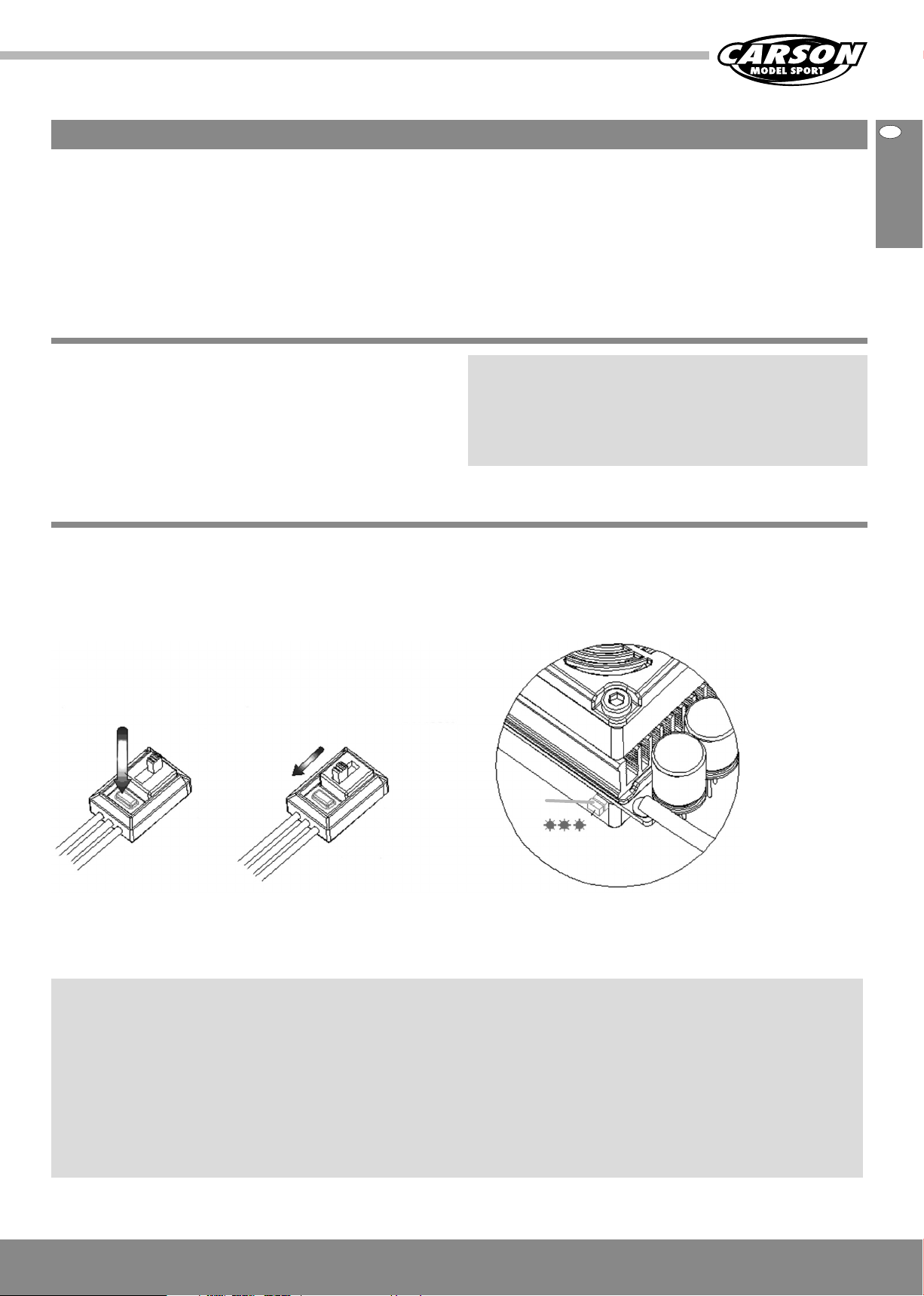
B) Halten Sie die „SETUP“-Taste des Reglers gedrückt und
schalten Sie dann den Regler ein. Lassen Sie die „SETUP“ Taste los, sobald die rote LED zu blinken beginnt.
Hinweis 1
Die „SET“-Taste des Reglers befindet sich am Ein-/Ausschalter
(siehe Bild).
Die „Set“-Taste drücken und anschalten.
OFF
ON
ON
Den Knopf loslassen sobald die LED blinkt.
OFF
Hinweis 2
Wenn Sie die „SET“-Taste nicht sofort loslassen, sobald die LED zu
blinken beginnt, wechselt der Regler in den Programmiermodus. In
diesem Fall schalten Sie den Regler bitte aus und kalibrieren erneut
den Gashebelbereich gemäß der Beschreibung.
LED
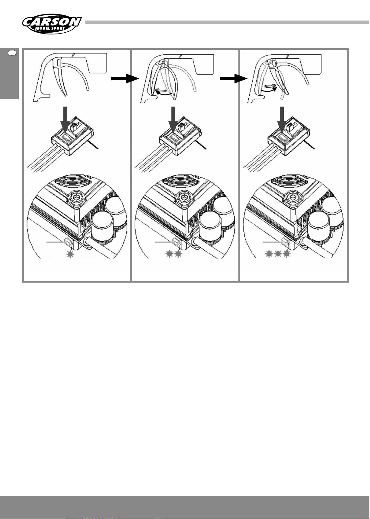
C) Stellen Sie die 3 Punkte gemäß den Schritten ein.
1. Neutralpunkt
Lassen Sie den Gashebel im Neutralpunkt und klicken Sie
anschließend auf die SET-Taste. Die grüne LED blinkt einmal auf.
2. Endpunkt Vorwärts
Ziehen Sie den Gashebel ganz nach hinten und klicken Sie
anschließend auf die SET-Taste. Die grüne LED blinkt zweimal auf.
3. Endpunkt Rückwärts
Drücken Sie den Gashebel ganz nach vorne und klicken Sie
anschließend auf die SET-Taste. Die grüne LED blinkt dreimal auf.
Der Gashebelbereich ist kalibriert und der Motor kann nach
3 Sekunden bewegt werden.
11CARSON FY8 Brushless 50 040 9091
Page 12
123
Neutralstellung
Drücke die „Set“-Taste
Drücke die „Set“-Taste
OFF
ON
LED LED LED
Endpunkt
Vorwärts
OFF
ON
Endpunkt
Rückwärts
Drücke die „Set“-Taste
OFF
ON
Grüne LED blinkt 1 Mal Grüne LED blinkt 2 Mal Grüne LED blinkt 3 Mal
12DCARSON FY8 Brushless 50 040 9091
Page 13

j. Erklärung des Gashebelbereichs
LED-Anzeige im normalen Betrieb
• Im normalem Betrieb leuchtet weder die rote noch die grüne LEDAnzeige, wenn sich der Gashebel im neutralen Bereich befindet.
• Die rote LED leuchtet, wenn das Auto vorwärts oder rückwärts fährt
und sie blinkt schnell, wenn das Auto bremst.
• Die grüne LED leuchtet, wenn der Gashebel zum höchsten Punkt
(Endpunkt) des Vorwärts-Bereichs oder des Rückwärts-Bereichs
Endpunkt/
Vollbremsung
Bremse und
Rückwärtsbereich
bewegt wird.
D
Vorwärts-
Bereich
Endpunkt/
Vollgas
Neutralpunkt
Warntöne
• Signalton für unnormale Eingangsspannung:
Der Regler überprüft beim Einschalten die Eingangsspannung.
Ist diese außerhalb des normalen Bereichs, wird ein Warn-Ton
ausgegeben:
„Piep-piep-, piep-piep-, piep-piep-“ (zwischen jedem „piep-piep-“
ist eine Pause von ca. 1 Sekunde).
• Signalton für unnormales Gassignal:
Kann der Fahrregler das normale Steuersignal nicht erkennen, wird
ein solcher Ton aus gegeben: „Piep-, piep-, piep-“ (zwischen den
einzelnen „Piep-“ -Tönen ist eine Pause von
ca. 2 Sekunden).
Schutzfunktion
1. Schutz gegen Unterspannungsausfall: Ist die Spannung eines
Lithium-Akkus für 2 Sekunden geringer als der Schwellenwert,
schaltet der Regler die Ausgangsleistung ab. Bitte beachten Sie,
dass der Regler nicht neu gestartet werden kann, wenn die
Spannung einer Lithium-Zelle unter 3,5 V liegt.
2. Schutz gegen Überhitzung: Liegt die Temperatur des Reglers länger
als 5 Sekunden über einem werkseitig voreingestellten Schwellenwert, schaltet der Regler die Ausgangsleistung ab. Setzt der
Überhitzungsschutz ein, blinkt die grüne LED wie folgt: „✼, ✼, ✼“
(Einzelblinken).
3. Schutz vor Verlust des Steuersignals: Der Regler schaltet die Ausgangsleistung ab, wenn das Signal für 0,2 Sekunden verloren geht.
Alle Einstellungen auf Standardeinstellung
zurücksetzen
Immer, wenn sich der Gashebel im neutralen Bereich befindet (außer
während der Kalibrierung oder im Programmiermodus), können Sie
die Taste „SET“ länger als 3 Sekunden gedrückt halten. Die rote und die
grüne LED blinken dann gleichzeitig. Dies bedeutet, dass alle
programmierbaren Einstellungen wieder auf die Standardwerte
zurückgesetzt wurden.
13CARSON FY8 Brushless 50 040 9091
Page 14

k. Steuern des Modells
• Stellen Sie das Modell so ab, dass die Räder frei in der Luft hängen.
• Drehen Sie das Steuerrad bis zum Anschlag nach rechts und links.
Die Räder sollen dem Lenkausschlag folgen.
• Schlagen die Räder entgegengesetzt ein, betätigen sie den
Servo-Reverse Schalter (ST in Position REV).
Neutral
Links
• Zum Regeln der Fahrgeschwindigkeit
betätigen Sie den Gas/Bremshebel
- Nach hinten
(Vorwärtsfahrt, Gas geben) bzw.
- Nach vorne (Bremsen, Rückwärtsfahrt).
it
rt).
Links
Rechts
Rechts
14DCARSON FY8 Brushless 50 040 9091
Bremsen/
Rückwärtsfahrt
Vorwärtsfahrt/
Gas geben
Page 15

l. Fehlersuchtabelle
Fehler Ursache Behebung
Das Modell fährt nicht Sender oder Empfänger sind nicht eingeschaltet Schalten sie den Sender oder Empfänger ein
Polarität der Akkus oder Akkutyp sind falsch Prüfen Sie die Polarität und den Akkutyp
Batterien/Akkus sind schwach oder ganz entleert Tauschen Sie die Batterien aus bzw. tauschen Sie
die Akkus oder laden sie die Akkus neu
Kontrollverlust Batterien/Akkus sind schwach oder ganz entleert Tauschen Sie die Batterien aus bzw. tauschen Sie
die Akkus oder laden sie die Akkus neu
Antenne fehlt oder ist nicht richtig befestigt Befestigen sie die Empfängerantenne und/oder
schrauben Sie die Senderantenne fest
In der Nähe wird ein anderes Modell auf der gleichen
Frequenz betrieben.
Modell fährt nicht
geradeaus
Modell bleibt nicht stehen Trimmung für den Gas/Bremshebel ist nicht korrekt
Modell fährt nicht rückwärts Trimmung für den Gas/Bremshebel ist nicht korrekt
Modell fährt zu langsam Batterien/Akkus sind schwach Tauschen Sie die Batterien aus bzw. tauschen Sie
Lenkungstrim ist nicht korrekt eingestellt Justieren Sie die Trimmung am Drehknopf
Radmuttern sind lose Ziehen Sie die Radmuttern fest an
eingestellt
eingestellt
Falsche Bedienung Steuern sie richtig
Motor hat an Leistung verloren Tauschen Sie den Motor aus
Die hinteren Radmuttern sind lose Ziehen Sie die Radmuttern fest an
Staub/Fremdkörper ist in das Getriebe gelangt Schalten Sie das Modell aus und reinigen Sie das
Fahren Sie woanders oder wechseln Sie die
Frequenz
Justieren Sie die Trimmung
Justieren Sie die Trimmung
die Akkus oder laden sie die Akkus neu
Getriebe
D
15CARSON FY8 Brushless 50 040 9091
Page 16

Dear Customer
We congratulate you for buying this CARSON RC model car, which is
designed using state of the art technology.
According to our policy of steady development and product
improvement we reserve the right to make changes in specifications
concerning equipment, material and design at any time without
notice.
Specifications or designs of the actual product may vary from those
shown in this manual or on the box.
Limited warranty
This product is warranted by CARSON against manufacturing defects
in materials and workmanship under normal use for 24 months from
the date of purchase from authorised franchisees and dealers. In
the event of a product defect during the warranty period, return the
product along with your receipt as proof of purchase to any CARSON
store.
CARSON will, at its option, unless otherwise provided by law:
(a) Correct the defect by repairing the product without charging for
parts and labour
(b) Replace the product with one of the same or similar design; or
(c) Refund the purchase price.
All replacement parts and products, and products on which a refund
is made, become the property of CARSON. New or reconditioned parts
and products may be used in the performance of warranty services.
Repaired or replaced parts and products are warranted for the
remainder of the original warranty period. You will be charged for
repair or replacement of the product made after the expiration of the
warranty period.
The manual forms part of this product. Should you ignore the
operating and safety instructions, the warranty will be void.
Keep this guide for future reference.
The Warranty does not cover:
• Damage or failure caused by or attributable to acts of God, abuse,
accident, misuse, improper or abnormal usage, failure to follow
instructions, improper installation or maintenance, alteration, lightning or other incidence of excess voltage or current;
• Damage caused by losing control of your car;
• Any repairs other than those provided by a CARSON Authorised
Service Facility;
• Consumables such as fuses or batteries;
• Cosmetic damage;
• Transportation, shipping or insurance costs; or
• Costs of product removal, installation, set-up service adjustment or
reinstallation
This warranty gives you specific legal rights, and you may also have
other rights which may vary according to the country of purchase.
Declaration of conformity
Dickie-Tamiya GmbH & Co. KG hereby declares that this model kit
with radio, motor, battery and charger is in accordance with the basic
requirements of the following European directives: 98/37 EG and
89/336/EWG and other relevant regulations of guideline 1999/5/EG
(R&TTE).
The original declaration of conformity can be obtained from the
following address:
Dickie-Tamiya GmbH & Co. KG • Werkstraße 1 • D-90765 Fürth •
Germany
The explanation of the symbol on the product,
packaging or instructions: Electronic devices are valuable products and should not be disposed of with the
household waste when they reach the end of their running time! Help us to protect the
environment and respect our resources by handing this
appliance over at the relevant recycling points.
We wish you good luck and a lot of fun driving
with your CARSON model car.
Before driving your new model carefully read these instructions!
16GBCARSON FY8 Brushless 50 040 9091
16
Page 17

Contents
s
Perface ........................................................................................................................16
Included Items ......................................................................................................... 17
Safety Precautions .................................................................................................. 18
Additional Items .....................................................................................................19
Tools Needed for the Assembly......................................................................... 20
a. Chassis .................................................................................................................. 20
b. Removing Body ................................................................................................. 21
c. Installation of Antenna ................................................................................... 21
d. Loading Battery.................................................................................................22
e. Insert Battery ..................................................................................................... 22
Included Items
Item
f. Turn on the RC System ................................................................................... 23
g. Technical Data Motor and ESC ....................................................................24
h. Connection/Cabeling .....................................................................................24
i. Basic Settings .....................................................................................................25
j. Throttle Range Explanation .......................................................................... 27
k. How to Control Your Model .......................................................................... 28
l. Troubleshooting ...............................................................................................29
Exploded View ......................................................................................................... 30
Spare Parts ................................................................................................................ 34
Transmitter
(only for RTR version)
GB
Chassis with body
17CARSON FY8 Brushless 50 040 9091
Page 18

Safety Precautions
Radio controlled models are not toys, operating
them has to be learned step by step.
• Children less than 14 years of age should drive the model only
together with a supervising adult.
Driving a radio controlled car is a fascinating hobby which has to be
practised with the necessary caution and respect.
A radio controlled model car can cause damage and injuries in case of
uncontrolled driving conditions and the user is liable for this.
Make sure that you have sufficient insurance coverage in practising
your hobby.
Only a well maintained model will
function in a correct manner.
Never start driving before you have made sure
the following points:
• Batteries for transmitter and receiver are well charged and of the
correct voltage.
• Always check the radio operation before starting the car.
• Make sure that all Servos respond correctly to the signals of the
transmitter.
• All operable parts are in good condition and you have tested their
operation.
Always switch on the transmitter first to avoid
any uncontrolled reaction of the receiver to a
foreign radio impulse.
Make sure that nobody in your environment controls a model with the
same frequency (number on the crystal).
Only use approved spare parts and never fit any unsuitable items.
It is the user’s responsibility to ensure that the model is functioning
correctly and that all nuts, bolts and screws are properly tightened.
• You have made sure that all screws are tightened.
• There is no other RC or similar transmitter nearby which could
cause interference.
Any further radio signal on the same frequency can cause the loss
of control for your model.
To end the operation switch off the receiver first,
then the transmitter.
• Keep your car away from high voltage cables or radio masts. Never
use the model when lightning is present!
• Atmospheric disturbances can affect the signals of your remote
controlling transmitter.
• The electrical connection of the model is not waterproof. Do not
use the model in wet areas. Therefore do not drive while raining,
snowing, in puddles or wet grass.
• Always avoid running radio control models in restricted, confined or
populated areas. Choose a sufficiently open & large area; it should
be free of obstacles.
• Keep away from roads, highways, people and animals!
• Do not drive, if you are overtired or your reactivity is impaired in
another way.
• Watch your model constantly and do not become distracted.
• The body shell should be correctly attached to the vehicle before
driving.
18GBCARSON FY8 Brushless 50 040 9091
• Allow cooling time for the engine components before removing
the body shell. These parts become extremely hot during operation
and could cause serious injury.
• Pay attention to charge announcement of your transmitter.
• Ensure that the batteries for the radio and receiver are fully charged
and of the correct voltage. When the batteries are running low you
might loose control of your model.
• Never use fully loaded batteries and batteries which have already
run low, or batteries of a different capacity at the same time.
• Never load batteries which are not rechargeable.
If not using the model for a longer time, the
rechargeable battery for driving has to be
removed absolutely.
Page 19

Finally
pg
fu
nction
y
h
Please read the instructions before operating your model.
Each time you have finished driving the model, always check the
correct operation of the components. A single loose screw can result in
a dangerous situation for your model. Maintain your model regularly
and replace damaged or worn out parts by genuine spare parts.
Additional Items
We wish you great fun with your CARSON model
car!
GB
For the transmitter: 50 060 9002 x2
8 pcs AA battery 1600 mAh
50 060 6045 Expert Charger 3
with LiPo function
50 001 3629 Charging cable
for transmitter
or
For the transmitter: 50 060 9000 x2
8 pcs AA battery 2300 mAh
50 090 6081 Charging cable
T-Plug
50 060 8101 LiPo battery
50 060 8101 LiPo batter
7,4 V/ 4400 mAh
7,4 V/ 4400 mA
19CARSON FY8 Brushless 50 040 9091
Page 20

Tools Needed for the Assembly
Modelling knife 30 007 4053
(small and big)
1,5 / 2 / 2,5 mm 30 007 4023
a. Chassis
Instant adhesive 30 005 3339
Hexagonal wrench 50 090 5065Philips screwdriver
Tweezers 30 007 4003
Scissors 30 001 3305Needle nose pliers 30 007 4034
Side cutter 30 007 4035
Front tyre
Chassis
On-/off switch
Motor
Spoiler
Driving battery
Steering servo
Rear shock
unit
Rear tyre
Front shock unit
20GBCARSON FY8 Brushless 50 040 9091
Speed contoller with ventilator
Page 21

b. Removing the Body
• Remove hook pin and
• Take body off.
GB
c. Installation of Antenna
• Thread the antenna cord through the antenna pipe.
Antenna cord Antenna pipe
21CARSON FY8 Brushless 50 040 9091
Page 22

d. Loading Battery
Beware:
For charging the battery, only use the recommended charger. Please consider the advice of the
enclosed instructions.
e. Insert Battery
1 Insert the battery.
2 Put the battery plate on it and
3 Fix it with the hook pins.
Advice
• Non-rechargeable batteries are not to be recharged.
• Rechargeable batteries are only to be charged under adult
supervision.
• Batteries are to be inserted with the correct polarity.
• Exhausted batteries are to be removed from the model.
• The supply terminals are not to be short-circuited.
• Regular examination of transformer or battery charger for any
damage to their cord, plug, enclosure and other parts.
22GBCARSON FY8 Brushless 50 040 9091
Page 23

f. Turn on the RC System
CAUTION!
Always turn the
transmitter´s
power switch ON first!
ON
GB
1 Connect the rechargeable battery for the driving.
2 Switch on the receiver.
3 Put the body on and fix it with the body split pins.
1
on
2
3
23CARSON FY8 Brushless 50 040 9091
Page 24

g. Technical Data Motor and ESC
Technical data motor: Brushless
Motor Sensorless
U/min 2230 UpV
U/min @ 14.8 V 33 000
Short term 72 A
Dimensions (A- Ø x L) 35.8 x 65 mm
Technical data ESC: Brushless
Forward yes
Reverse yes
Input voltage 2 - 4 LiPo-cells/6 - 12 NimH cells
h. Connection/Cabling
Connect the ESC, motor, receiver,
battery and servo according to the following
diagram.
Positive (+) and negative (-) wires of the ESC are connected with the
battery pack.
A, B and C are connected with the motor wires. The control cable of
the ESC (wires in black, red and white colour) is connected with the
throttle channel of the receiver (usually CH2).
The A, B, C wires of the ESC can be connected with the motor wires
freely (without any order).
If the motor runs in the opposite direction, please swap any two wire
connections.
If there are 2 battery packs, which need to be
connected in series, please refer to the
following picture.
Red wire +
Red wire to the positive
of the ESC
Black wire to the negative
of the ESC
Black wire –
Black wire –
Red power wire
+
(battery
positive)
Black power
-
wire (battery
negative)
24GBCARSON FY8 Brushless 50 040 9091
Page 25

i. Basic Settings
Throttle range setting (throttle range calibration)
In order to make the ESC fit the throttle range of your transmitter, you
must calibrate it for the following cases; otherwise the ESC cannot work
properly.
There need to be set 3 points. They are the end point of “forward”, the
end point of ”backward” and the neutral point.
The following pictures show how to set the throttle range with your
transmitter.
1) Begin to use a new ESC
2) Begin to use a new transmitter
3) Change the settings of neutral position of the throttle lever, the ATV
or EPA parameters, etc.
A) Switch off the ESC and turn on the transmitter.
B) Hold the “SETUP”-key of the ESC and then switch on the ESC.
Release the “SETUP” key as soon as the red LED begins to
flash.
GB
Note 1
The “SET” key of ESC is at the power switch (see picture).
Hold the SET key and then turn on the switch.
OFF
ON
OFF
ON
Release the SET key as soon as the red LED flashes.
Note 2
If you don’t release the “SET” key as soon as the red LED begins to flash,
the ESC will enter the program mode. In such case, please switch off
the ESC and re-calibrate the throttle range again as described.
LED
C) Set the 3 points according to the steps.
1. The neutral point
Move the throttle lever at the neutral point, and then click the SET
key. The green LED flashes 1 time.
2. The end point of forward direction
Move the throttle lever at the end point of forward direction, and
then click the SET key, the green LED flashes 2 times.
3. The end point of backward direction
Move the throttle lever at the end point of backward direction, and
then click the SET key, the green LED flashes 3 times.
The throttle range is calibrated; the motor can be started after
3 seconds.
25CARSON FY8 Brushless 50 040 9091
Page 26

123
At the neutral
point
Click SET key
Click SET key
OFF
ON
LED LED LED
At the
toppoint
(Forward)
OFF
ON
At the
top point
(Backward)
Click SET key
OFF
ON
Green LED flashes
for 1 time
Green LED flashes
for 2 times
Green LED flashes
for 3 times
26GBCARSON FY8 Brushless 50 040 9091
Page 27

j. Throttle Range Explanation
Top point/
maximum brake
Brake and
backward zone
LED status of normal running
• In normal use, if the throttle stick is in the neutral range, neither the
red LED nor the green LED lights.
• The red LED lights when the car is running forward or backward and
it will flash quickly when the car is braking.
• The green LED lights when the throttle stick is moved to the top
point (end point) of the forward zone or backward zone.
GB
Forward
zone
Top point/
maximal throttle
Neutral point
Alert tones
• Alert tone input voltage abnormal:
The ESC begins to check the input voltage when power on. If it is
out of the normal range, such an alert tone will be emitted:
“beep-beep-, beep-beep-, beep-beep-” (There is 1 second time
interval between every “beep-beep-” tones).
• Alert tone throttle signal abnormal:
When the ESC can’t detect the normal throttle signal, such an alert
tone will be emitted:
“beep-, beep-, beep-” (There is 2 seconds time interval between
every “beep-” tones).
Protection function
1. Low voltage cut-off protection: If the voltage of a lithium battery
pack is lower than the threshold for 2 seconds, the ESC will cut of
the output power. Please note, that the ESC cannot be restarted if
the voltage of one lithium cell is lower than 3.5 V.
2. Over-heat protection: When the temperature of the ESC is over a
factory preset threshold for 5 seconds, the ESC will cut off the
output power. When the over-heat protection happens, the green
LED will flash in such a style: “✼, ✼, ✼” (single flash).
3. Signal loss protection: The ESC will cut off the output power if the
throttle signal is lost for 0.2 second.
Reset all items to default values
At any time when the throttle is located in neutral zone (except in the
throttle calibration process or ESC program mode), you can hold the
“SET” key for over 3 seconds. The red LED and green LED will flash at
the same time, which means each programmable item has be reset to
its default value.
27CARSON FY8 Brushless 50 040 9091
Page 28

k. How to Control Your Model
)
• Raise the tyres off the ground.
• Turn the steering wheel to the right and left as far as it will go.
The wheels are to follow the steering direction.
• If the wheels operate in the opposite direction, operate the servo
Reverse switch (ST in position REV).
Neutral
Left
• For regulating the driving speed
operate the gas/brake lever
- Lever to the rear
(driving forward, to give speed)
- Fforward (braking, reverse movement)
nt
Left
Right
Right
28GBCARSON FY8 Brushless 50 040 9091
braking,
reverse
movement
driving forward,
to give speed
Page 29

l. Troubleshooting
Problem Cause Correction
Model doesn´t move Transmitter or chassis power switch is not ”ON“ Switch power on receiver or transmitter
Polarity or battery type is wrong Check polarity and type of battery
Batteries have run down Change batteries or charge them
Loss of control Batteries have run down Change batteries or charge them
Antenna is missing or not attached properly Attach receiver antenna and/or transmitter antenna
screw tight
R/C model using same band (frequency) is nearby Run model in different area or change crystal
Doesn´t run straight Steering trim is not adjusted correctly Make adjustment
Front and rear wheel nuts are too lose Tighten wheel nuts
Doesn´t stop Throttle trim is not adjusted correctly Make adjustment
Doesn´t reverse Throttle trim is not adjusted correctly Make adjustment
Wrong action Control properly
Running too slowly Batteries have run down Change batteries or charge them
Motor has lost power Change to spare motor
Rear wheel nuts are too loose Tighten wheel nuts
Dust or foreign objects are inside gears Turn the power switch ”OFF“ and clean out gears
GB
29CARSON FY8 Brushless 50 040 9091
Page 30

0
5
2
2
0
Explosionszeichnung • Exploded View
50 040 5337
50 040 5312
50 040 5227
50 040 5288
50 040 5312
50 040 5337
50 040 5288
50 040 5276
50 040 5337
50 040 5337
50 040 5329
50 040 5256
50 040 5323
50 040 5340
50 040 5260
50 040 5262
50 040 5280
50 040 5337
50 040 5327
50 040 5318
50 040 5313
50 040 5340
50 040 5317
50 040 5267
50 040 5332
50 040 5289
50 040 5258
50 040 5257
50 040 5268
50 040 5315
50 040 5267
50 040 5336
50 040 5262
50 040 5337
50 040 5337
50 040 5337
50 040 5318
50 040 5313
50 040 5269
50 040 5267
50 040 5337
50 040 5324
50 040 526
50 040 5340
50 040 5260
50 040 5340
50 040 53
50 040 531
5
Montage
50 080 1013
50 080 1013
50 040 5340
50 040 5336
50 040 5340
50 040 5336
50 040 5336
50 040 5336
50 040 5340
50 040 5336
50 040 5336
50 040 5311
50 090 6127
50 040 5336
50 040 5340
50 040 5336
50 040 5336
50 040 5336
50 040 5336
50 040 5314
50 040 5340
50 040 5336
50 040 5338
50 040 53
50 040 5340
50 040 5260
50 040 5329
50 040 5334
50 04
50 040 5276
30 CARSON FY8 Brushless 50 040 9091
Page 31

2
50 040 5339
50 040 5326
50 040 5329
0
50 040 5280
50 040 5340
50 040 5317
50 040 5267
50 040 5338
5324
5319
50 040 5288
50 040 5337
50 040 5324
50 040 5276
50 040 5328
50 040 5321
50 040 5258
50 040 5328
50 040 5333
50 040 5337
50 040 5289
50 040 35
50 040 35
50 040 5327
50 040 5280
50 040 5331
50 040 5318
50 040 5337
50 040 5337
50 040 5340
50 040 5273
50 040 5329
50 040 5260
50 040 5339
50 040 5288
50 040 5319
50 090 6126
50 040 5322
50 040 5276
50 040 5312
50 040 5337
0 5327
50 040 5273
340
60
50 040 5337
0 040 5288
50 040 5331
50 040 4280
50 040 5340
50 040 5317
50 040 5337
50 040 5257
50 040 5326
50 040 5318
50 040 5275
50 040 5312
50 040 5336
50 040 5267
50 040 5337
50 040 5334
50 040 5269
50 040 5275
50 040 5310
50 040 5275
50 040 5312
Montage
50 080 1013
31CARSON FY8 Brushless 50 040 9091
Page 32

N° Bezeichnung Description
50 040 5256 Frontrammer Frontbumper
50 040 5257 Querlenkerhalter 2 Stück Suspension arm mount 2 pcs
50 040 5258 Querlenkerhalter oben vorne/hinten Upper suspension arm mount fr/rear
50 040 5259 Felgenmitnehmer mit Pin 4 Stück Rim hub w/pin 4 pcs
50 040 5260 Radachse mit Pin 2 Stück Axle w/pin 2 pcs
50 040 5261 Lenkhebel L/R Front/rear steering arm
50 040 5262 Radträger vorne L/R Fr/Rr C-hub carrier
50 040 5263 Querlenker vorne/unten L/R Front Lower suspension arm L/R
50 040 5264 Mittelantriebswelle 2 Stück Driver shaft set 2 pcs
50 040 5265 Seitenschutzplatten Side guard plate L/R
50 040 5266 Karosseriehalter vorne Body post front
50 040 5267 Querlenkerstifte vorne kurz 4 Stück/ 4 Stück lang Front suspension arm pin short 4 pcs
suspension arm pin long 4 pcs
50 040 5268 Chassis-Front Front chassis
50 040 5269 Unterer Querlenkerhalterblock V/H Lower suspension mount block fr/rr
50 040 5270 Lenkgestängeset 2 Stück Steering linkage set 2 set
50 040 5271 Servosavereinheit Servo saver unit
50 040 5272 Lenkservogestänge Steering servo horn and linkage
50 040 5273 Radträger hinten L/R Hub rear carrier
50 040 5274 Querlenker hinten/unten L/R Rear lower suspension arm l/r
50 040 5275 Querlenkerstifte hinten kurz 4 Stück Rear suspension arm pin short 4 pcs
50 040 5276 Schrauben, Muttern, Beilagscheiben Screws, nuts, washers
50 040 5277 Senkschrauben 48 Stück Flat cross screw 48 pcs
50 040 5278 Linsenkopfschrauben 84 Stück B-head cross screw 84 pcs
50 040 5279 Diffmitnehmer Diff. outdrive
50 040 5280 Kugellagerset 8 Stück Ball bearing 8 pcs
50 040 5281 Pins 12 Stück/Clipse 24 Stück Pin 12pcs + clips 24 pcs
50 040 5283 Differenzial komplett Differential unit
50 040 5284 Diffgehäuse Diff gearbox upper/lower
50 040 5285 Pin-Schrauben 12 Stück Screw pin 12 pcs
50 040 5286 Hauptrahmen-Stifte Main frame shaft
50 040 5287 Chassisplatte Chassis
Montage
50 040 5288 Reifenset 2 Stück Tire unit 2 pcs
50 040 5289 Dämpferbrücke Shocktower
32 CARSON FY8 Brushless 50 040 9091
Page 33

N° Bezeichnung Description
50 040 5310 Spoilerhalterungs-Set FY8 Wing mount
50 040 5311 Chassisplatte Chassis plate
50 040 5312 Stoßdämpferset 2 Stück Shock absorber 2 pcs
50 040 5313 Querlenkerset vorne unten Li/Re Suspension arm mount 2 pcs
50 040 5314 Servosaver-Gestänge Servosaver link
50 040 5315 Abdeckung vorne Upper deck front
50 040 5316 Seitenschutz L/R Side guards l/r
50 040 5317 O-Scheiben 8 Stück O-washer 8 pcs
50 040 5318 Antriebswellen v/h 2 Stück Drive shafts f/r
50 040 5319 Mitteldifferenzial komplett Center diff unit complete
50 040 5320 Mittelantriebswelle vorne Center drive shaft front
50 040 5321 Mittelantriebswelle hinten Center drive shaft rear
50 040 5322 Motorritzel 15 Z Motor gear 15 t
50 040 5323 Lenkhebel L/R Knuckle arms l/r
50 040 5324 Lenkgestänge-Set 2 Stück Steering linkage set
50 040 5325 Differenzial Zahnrad-Set Driven gear bevel set
50 040 5326 Differenzial v/h komplett Diff gearbox unit f/r complete
50 040 5327 Querlenker oben v/h 2 Stück Upper suspension arms 2 pcs
50 040 5328 Empfänger-Box Receiver-case
50 040 5329 Radmitnehmer 17 mm Rim hub with pin
50 040 5330 Hauptzahnrad 46 Z Spur gear 46 t
50 040 5331 Querlenkerset hinten unten L/R Rear suspension arms l/r
50 040 5332 Servosaver komplett Servosaver unit
50 040 5333 Oberdeckhalterung v/h Front rear upper deck mount
50 040 5334 Servohalter/Chassisabschluss-Set Rear chassis/steering servo mount
50 040 5335 Oberdeck/Kabelführungs-Set Upper deck wire mount
50 040 5336 Senkschraubenset FY8 Flat cross screw set
50 040 5337 Linsenkopfschraubenset FY8 B-head cross screw set
50 040 5338 Akkuhalterungs-Set Battery base/cover
50 040 5339 Differenzial Mitnehmer/Karosseriehalter FY8 Diff outdrive pin/body post
50 040 5340 Muttern/Beilagscheiben-Set FY8 Washer, pins, ball end set
50 080 1013 Karosserie FY8 + Spoiler Body FY8 + spoiler
50 090 6126 Brushless motor FY8 Brushless motor FY8
50 090 6127 Brushless Regler FY8 Brushless esc FY8
Montage
33CARSON FY8 Brushless 50 040 9091
Page 34

Ersatzteile
Spare Parts
50 040 5267 Querlenker Pin 4x lang, 4x kurz
Front susp. arm pin 4x l., 4x short
50 040 5280 8x Kugellager
8x Ball bearings
50 040 5256 Rammer vorne
Front bumper
50 040 5257 2x Querlenkerhalterung
2x Suspension arm mount
50 040 5258 Querlenkerhalterung oben v + h
Upper suspension mount f + r
50 040 5268 Stoßfänger vorne
Front damper
50 040 5269 Unterer Querlenker v + h
Lower susp. mount block f + r
50 40 5273 Nabenhalterung hinten
Hub rear carrier
50 040 5286 Hauptwelle
Main frame shaft
50 040 5288 2x Reifenset
2x Tyre unit
50 040 5289 Dämpferbrücke
Shocktower
50 040 5260 2x Achse
2x Axle
50 040 5262 C-Halterung vorne + hinten
Ersatzteile
C-carrier front + rear
50 040 5275 4x Querlenker Pin hinten
4x Reat suspension arm pin
3 x 34.5 mm
50 040 5276 M12 Nuss
Nut M12
50 040 5279 Differenzialzapfen Set
Diff. outdrive set, M4 x 4 mm
34 CARSON FY8 Brushless 50 040 9091
50 040 5310 Spoilerhalter-Set
Wing mount set
Page 35

Ersatzteile • Spare Parts
50 040 5311 Chassisplatt
Chassis plate
50 040 5317 8x O-Ringe
8x O-washer
50 040 5324 2x Lenkgestänge
2x Steering linkage
50 040 5312 2x Stoßdämpfer (Kunststoff )
2x Shock absorber unit (plastic)
50 040 5313 2x Querlenker vorne l + r
2x Front suspension arms l + r
50 040 5318 2x Antriebswelle l + r
2x Transverse drive shaft l + r
50 040 5319 Zentraldifferenzial komplett
Centre differential unit complete
50 040 5320 Antriebswelle vorne
Centre drive shaft front
50 040 5325 Antriebs- + Diff-Zahnräder
Driving + diff gear set
50 040 5326 Differenzial v/h komplett
Diff gear box unit f/r complete
50 040 5314 Servo Saver Gestänge
Servo saver link
50 040 5315 Abdeckung vorne
Upper deck front
50 040 5316 Seitenschutz links/rechts
Side guard plate left/right
50 040 5321 Antriebswelle hinten
Centre drive shaft rear
50 040 5322 Motorritzel mit Madenschraube
Motor gear with grub screw
15 T
M3
50 040 5323 Metall Achsschenkel links/rechts
Metal knuckle arm left/right
50 040 5327 2x Querlenker oben
2x Upper suspension arm
Ersatzteile
35CARSON FY8 Brushless 50 040 9091
Page 36

Ersatzteile • Spare Parts
50 040 5328 Empfängerbox
Receiver case
50 040 5333 Oberdeckhalterung v + h
Upper deck mount front + rear
50 040 5338 Akkubox und Abdeckung
Battery base and cover
50 040 5329 Radmitnehmer mit Pin
Rim hub with pin
50 040 5330 Zahnrad 46 Z
Spur gear 46 T
50 040 5331 2x Querlenker hinten l + r
2x Rear suspension arm l + r
50 040 5334 Chassishalterung hinten
Rear chassis/steer./servo mount
50 040 5335 Halterung oben
Upper deck/wire mount
50 040 5336 60x Flachkopf-, 12x Schrauben
60x Flat cross screw, 12x scr. pin
50 040 5339 Diff-Mitnehmer + Karosseriepin
Diff outdrive pin + body post
50 040 5340 24x Unterlegscheiben, 12x Pin,
6x Kugelkopf-, 18x Schrauben,
5x Klemmmutter
24x Washer, 12x pin, 6x d. way
ball end, 18x screw, 5x locknut
50 040 5332 Servosaver Set
Ersatzteile
Servo saver unit
50 040 5337 104x Schrauben
104x B-head cross screw
36 CARSON FY8 Brushless 50 040 9091
Page 37

Ersatzteile • Spare Parts
50 080 1013 Karosserie + Spoiler
Body + tail wing
50 090 6126 Brushless Motor
Brushless motor
50 090 6127 Brushless Regler
Brushless ESC
Ersatzteile
37CARSON FY8 Brushless 50 040 9091
Page 38

Notizen
38 CARSON FY8 Brushless 50 040 9091
Page 39

Notizen
39CARSON FY8 Brushless 50 040 9091
Page 40

For Germany:
Service-Hotline:
Mo - Do 8.00 – 17.00 Uhr
Fr 8.00 – 14.30 Uhr
0180 5–73 33 00
14 ct/min
CARSON-MODEL SPORT
Abt. Service
Mittlere Motsch 9
96515 Sonneberg
CARSON-MODEL SPORT
Werkstraße 1 • D-90765 Fürth • Germany
www.carson-modelsport.com
 Loading...