

Page 1

Reex 6/14Ch
Switch 2/4
DE // Betriebsanleitung
GB // Instruction Manual
FR // Avertissement de sécurité
+49 3675 7333 343
Service-Hotline for Germany: Mo - Do 8.00 - 16.00 Uhr // Fr 8.00 - 13.00 Uhr
CARSON-Model Sport // Abt. Service // Mittlere Motsch 9 // D-96515 Sonneberg
TAMIYA-CARSON Modellbau GmbH & Co. KG // Werkstraße 1 // D-90765 Fürth
www.carson-modelsport.de
500503060 / 500503061 // Stand: Januar 2019
IT // Avvertenze di sicurezza
ES // Indicaciones de seguridad
NL // Veiligheidsinstructies
Page 2
DE // Betriebsanleitung
Bedeutung des Symbols auf dem Produkt, der Verpackung oder Gebrauchsanleitung: Elektrogeräte sind Wertstoffe und gehören am Ende der
Laufzeit nicht in den Hausmüll! Helfen Sie uns bei Umweltschutz und Recourcenschonung und geben Sie dieses Gerät bei den entsprechenden
Rücknahmestellen ab. Fragen dazu beanwortet Ihnen die für Abfallbeseitigung zuständige Organisation oder Ihr Fachhändler.
SCHALTMODULE
Die Schaltmodule werden direkt an einem RC- Empfänger angeschlossen und können über einen Taster, Schalter oder Knüppel gesteuert werden. Dabei
wird die Pos ition des Schalte rs (oben und unten) und die Dau er (kurz und lang) aus gewertet. Bei d em 2-fach Modul wird l ediglich die Posit ion ausgewerte t.
Bei Tastern und Schaltern ist darauf zu achten, dass diese eine Mittelstellung besitzen. Jeder Schaltausgang verfügt über eine Memoryfunk tion, dass heißt
ein Schaltausgang bleibt so lange aktiviert bis der Schalter wieder in Neutralstellung gebracht wurde und erneut in die gleiche Position gebracht wird. Auf
den Schaltmodulen stehen 4 bzw. 2 getrennte und minusschaltende Ausgänge zur Verfügung. Die Ausgänge verfügen über jeweils ein 20 cm langes blaues
Kabel. Die ses Kabel ist mit d em Minuspol des Verb rauchers zu verbi nden. Jeder Schal tausgang kann ein en Strom von max. 2,5 A sch alten. Die maximal
zulässige Versorgungsspannung beträgt 16 V. Das Schaltmodul versorgt sich selbst über die Spannung des Servokabels. Das schwarze Minuskabel kann
direkt am Akku oder an der Verteilerklemme angeschlossen werden. Bei hohen Lasten ist unbedingt das schwarze Kabel anzuschließen um Schäden am
Empfänger zu vermeiden.
TECHNISCHE DATEN
Eingangsspannung:
Eingangsstrom: ca. 18 mA bei 5 V
Ausgänge: 2 oder 4 Stück
Schaltspannung: Maximal 16 V
Schaltstrom: Maximal 2, 5 A pro Ausgang
Anschlusskabel: Ausgänge: 2 /4 blaue Siliko nkabel mit je 200 mm
Abmessung: 16 x 14 x 4 mm
Gewicht: 10 g
4 - 8 V vom Empfä nger
Länge und 0, 25 mm²
Servo anschluss: 300 mm Se rvokabel mit
UNI-Stecker
Minuskab el: Silikonkabel mit 2 00 mm Länge
und 0,5 mm²
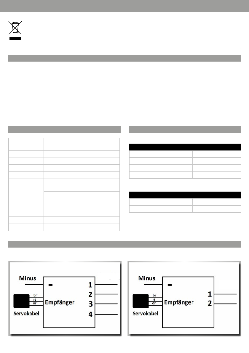
ANSCHLUSSBELEGUNG
4-fach M odul:
Ausgänge 1 bis 4
SCHALTVERHALTEN
4-fach M odul:
Schalterstellung Ausgänge
Lang in Position "oben" Ausgang 1
Kurz in Position "oben" Ausgang 2
Kurz in Pos ition "unten" Ausgang 3
Lang in Position "unten" Ausgang 4
2-fac h Modu l:
Schalterstellung Ausgänge
Kurz in Position "oben" Ausgang 1
Kurz in Pos ition "unten" Ausgang 2
2-fac h Modu l:
Ausgänge 1 bis 2
Page 3
GB // Instruction Manual
Meaning of the symbol on the product, packaging or instructions for use: Elec trical appliances contain valuable recyclable materials and
should not b e discarded in the d omestic waste a t the end of their ser vice life! Help us pr otect the enviro nment and conser ve resources by
taking th is appliance to the app ropriate local r ecycling centr e. Your local w aste management or ganisation or spe cialist dealer wil l be able to
answer any qu eries you may have.
SWITCH MODULES
The switc h modules are conne cted direc tly to a RC receiver and c an be controlled via a p ush-button, s witch or joystic k. The position of t he switch (up and
down) and the du ration (short and l ong) are evaluated her e. In the case of the 2-way mo dule, only the posit ion is evaluated. It sh ould be noted that the
push-bu ttons and switc hes have a middle posi tion. Every swi tching output has a me mory funct ion, i.e. it remains ac tivated until the s witch has been
return ed to the neutral po sition and then bro ught into the same po sition again. The num ber of separate ne gative switching o utputs availabl e on the switch
modules i s 4 and 2 respectiv ely. Each of the outpu ts has a blue lead 20cm i n length. This lead mu st be connecte d to the consumer’s negat ive terminal. Each
switchi ng output can swi tch a maximum cur rent of up to 2.5A. The max imum permissibl e supply voltage is 16 V. The swi tching module draw s its supply
from the vo ltage on the ser vo cable. The black ne gative lead can be con nected direc tly to the batte ry or to the distr ibution terminal . With high loads it is
imperat ive to connect the b lack lead to avoid damage t o the receiver.
TECHNICAL DATA
Input voltage: 4 - 8V from the r eceiver
Input current: Approx. 18mA a t 5V
Outputs: 2 or 4 off
Switching voltage: Maximum 16V
Switching current: Ma ximum 2.5A per output
Connecting leads: Output s: 2/4 blue silicone lead s each 200mm in
length an d 0.25 mm²
Servo co nnection: 300 mm s ervo lead with UNI
connector
Negative l ead: Silicone lead 200 mm i n length
and 0.5 mm²
Dimensions: 16 x 14 x 4 mm
Weigh t: 10 g
4-way module:
2-way module:
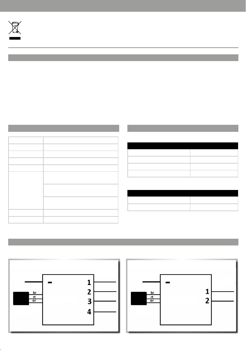
PIN ASSIGNMENT
4-way module:
Outputs 1 to 4
2-way module:
Minus Minus
SWITCHING ACTION
Switch position Outputs
Long in "top” position Output 1
Short in "top” position Output 2
Short in "bottom” position Output 3
Long in "bottom” position Output 4
Switch position Outputs
Short in "top” position Output 1
Short in "bottom” position Output 2
Outputs 1 to 2
Receiver Receiver
Servo cable Servo cable
Page 4

FR // Avertissement de sécurité
Signif ication du symb ole sur le produit, l ’emballage o u le mode d’emploi: Les appa reils électri ques sont des biens p otentiellement r ecyclables
qui ne doivent pas être jetés aux ordures ménagères une fois usés. Aidez-nous à protéger notre environnement et à économiser nos
ressour ces et remettez c et appareil à un lieu de c ollecte appro prié. Si vous avez des que stions sur l’éliminat ion des déchet s, adressez-vous au x
organisations compétentes ou à votre revendeur.
MODULES DE COMMUTATION
Les module s de commutation s ont directeme nt raccordés à un réce pteurRC et peuvent êt re commandés via un e touche, un commutat eur ou une manette.
La posit ion du commutateur (en hau t et en bas) et la durée (br ève et longue) sont alor s évaluées. Pour le mo dule double, seule la p osition est éval uée. En
ce qui concer ne les touches et le s commutateurs, t enir compte du fait qu ’ils ont une positio n intermédiaire. C haque sortie de c ommutation disp ose d’une
fonct ion mémoire. Cela sign ifie qu’une sor tie de commutatio n reste activé e jusqu’à ce que le commu tateur soit mis en p osition neutre pu is de nouveau
dans la même p osition. Les modul es de commutation p résentent 4 ou 2 sor ties séparée s et à commutation n égative. Chacune de s sorties disp ose d’un câble
bleu de 20cm de l ong. Ce câble doit êt re raccordé au pôle n égatif du consomma teur. Chaque sortie d e commutation peu t commuter un couran t de 2,5A
maximum . La tension d'alimenta tion maximale adm issible est de 16V. Le module de co mmutation s’aliment e lui-même par le biai s de la tension du câble
de servo commande. Le câble p ôle négatif noir pe ut être raccordé di rectement sur l ’accu ou sur la b orne du répart iteur. En cas de charge él evée, le câble noir
doit impérativement être raccordé afin d’éviter tout endommagement du récepteur.
CARACTÉRISTIQUES TECHNIQUES
Tension d’entrée: 4 - 8V du récepteu r
Courant d 'entrée: env. 18 mA pour 5V
Sorti es: 2ou 4éléments
Tension de commutation:
Courant d e commutati on:
Câble de raccordement:
Dimensions: 16 x 14 x 4mm
Poids: 10 g
maximum 16V
maximum 2, 5A par sortie
Sorti es: 2/4 câble en silicone b leu de 200mm de
long et 0,25 m m² chacun
Raccorde ment servocomm ande: câble de ser vocommande d e 300mm avec connect eurUNI
Câble pôl e négatif: câble en si licone de 200mm
de long et 0,5 mm ²
COMPORTEMENT DE COMMUTATION
Module quadruple:
Position du commutateur Sorties
Long en po sition «en haut» Sorti e 1
Court e n position «en hau t» Sorti e 2
Court e n position «en bas» Sortie 3
Long en po sition «en bas» Sortie 4
Module d ouble:
Position du commutateur Sorties
Court e n position «en hau t» Sorti e 1
Court e n position «en bas» Sortie 2
AFFECTATION DES RACCORDEMENTS
Module quadruple:
Sorties 1à 4
Module d ouble:
Négatif Négatif
Sorties 1à 2
Câble de servocommande
Récepteur Récepteur
Câble de ser
vocommande
-
Page 5

IT // Avvertenze di sicurezza
Signif icato del simbolo s ul prodotto, sulla co nfezione o nelle is truzioni per l’us o: gli apparecchi ele ttrici sono p rodotti ricic labili e quindi,
al termine d el loro ciclo di vit a, non devono essere g ettati tra i ri fiuti domes tici. Aiutateci a t utelare l’ambiente e a pr eservare le ris orse,
consegn ando questo appar ecchio presso i re lativi centri di ra ccolta. Per domande i n proposito rivol gersi all’ente respon sabile dello
smaltime nto dei rifiuti o a l proprio rivendi tore specializ zato.
MODULI DI COMMUTAZIONE
I moduli di co mmutazione veng ono collegati dire ttamente a un rice vitore RC e possono e ssere gestit i attraverso un t asto, un interrut tore o una cloche. C iò
consente d i valutare la posizi one dell'interru ttore (in alto e in bas so) e la durata (breve e lung a). Del modulo d oppio viene analiz zata solo la posi zione. Tenere
conto del f atto che i tasti e gl i interruttor i dispongono di una p osizione central e. Ogni uscita di com mutazione pres enta una funzion e Memory, ossia rima ne
attiva f ino a quando l'inter ruttore non r itorna nella stes sa posizione dop o essere stato ri portato in posi zione di folle. Sui mod uli di commutazio ne sono
disponib ili 4 o 2 uscite separ ate a commutazione n egativa. Le uscit e dispongono risp ettivamente di u n cavo blu lungo 20 cm. Tale cavo d eve essere collega to
al polo neg ativo dell'utenza. O gni uscita di commu tazione è in grado d i commutare una cor rente di max. 2,5 A. L a tensione di aliment azione massima
consenti ta è pari a 16 V. Il modulo di commut azione si aliment a tramite la tensione d el cavo del servo comando. Il cavo negat ivo nero può essere c ollegato
direttamente all'accumulatore o al morsetto del distributore. Con carichi elevati, è indispensabile collegare il cavo nero per evitare danni al ricevitore.
DATI TECNICI
Tensione di ingresso: 4 - 8 V dal ricevitor e
Corrente di entrata: ca. 18 mA a 5 V
Uscite: 2 o 4 pezzi
Tensione di commutazione:
Corrente di commutazione:
Cavo di collegamento: Uscite: 2/4 cav i in silicone blu da 200 mm d i
Dimensione: 16 x 14 x 4 mm
Peso: 10 g
max. 16 V
max. 2,5 A per u scita
lunghez za e 0,25 mm²
Collegame nto del servocom ando: cavo del
servo comando da 300 mm con spi na UNI
Cavo negat ivo: cavo in silicone da 20 0 mm
di lunghez za e 0,5 mm²
REAZIONE
Modulo quadruplo:
Posizione dell'interruttore Uscite
Lungo in posizione "in alto" Uscita 1
Corto in posizione "in alto" Uscita 2
Corto in posizione "in basso" Uscita 3
Lungo in posizione "in basso" Uscita 4
Modulo doppio:
Posizione dell'interruttore Uscite
Corto in posizione "in alto" Uscita 1
Corto in posizione "in basso" Uscita 2
OCCUPAZIONE DEI COLLEGAMENTI
Modulo quadruplo:
Uscite 1-4
Modulo doppio:
Negativo Negativo
Usc ite 1-2
Cavo del servocomando
Ricevitore Ricevitore
Cavo del ser
vocomando
-
Page 6

ES // Indicaciones de seguridad
Signif icado de los símbo los sobre el produ cto, el embalaje o el man ual de instruccio nes: Los disposit ivos eléctric os son desechos r eciclables y
no deben ti rarse en la basura d oméstica al f inal de su vida útil. Ayúd enos a proteger el me dio ambiente y a pres ervar los recu rsos entregand o
este disp ositivo en los corr espondientes pu ntos de recogida. Pu ede dirigir sus pre guntas al respe cto al organismo re sponsable de la re cogida
de residuo s o su comercio espe cializado.
MÓDULOS DE CONMUTACIÓN
Los módulo s de conmutación s e conectan dire ctamente a un rec eptor RC y pueden mane jarse mediante te clas, interrupto res o palancas. Par a ello se
analizan l a posición del inter ruptor (arriba y aba jo) y la duración (corta y la rga). En el módulo doble se an aliza únicamente l a posición. En el cas o de las
teclas y los i nterruptores ha y que observar qu e poseen una posici ón intermedia. Ca da salida de conmut ación dispone de una f unción de memori a, esto
signif ica que una salida de c onmutación per manece activa ha sta que el interr uptor se haya coloc ado de nuevo en posició n neutra y se devuel va a la misma
posició n. En los módulos de con mutación se encu entran disponibl es 4 o, dado el caso, 2 salid as separadas de conm utación negati va. Las salidas dis ponen de
un cable az ul de 20 cm de longitud , respectiva mente. Este cable d ebe conectar se con el polo negati vo del consumidor. Cada s alida de conmutac ión puede
conmutar u na corriente máx . de 2,5 A. La tensión de ali mentación máxi ma admisible es de 16 V. El módulo de c onmutación se au toalimenta media nte la
tensión de l servocable. El c able negativo neg ro se puede conec tar directa mente a la batería o al suj etacables de dis tribución. En el c aso de cargas elev adas es
impresc indible conec tar el cable negr o para prevenir que el r eceptor sufra da ños.
DATOS TÉCNICOS
Tensión de entrada: 4 - 8 V del r eceptor
Tensión de entrada: apr ox. 18 mA con 5 V
Salidas: 2 o 4 uni dades
Tensión de conmutación: Máxim a 16 V
Corriente de conmutación: Máx ima 2,5 A por salida
Cable de conexión: Salidas: 2/4 cables de s ilicona azules
de 200 mm de lon gitud y 0,25 mm²,
respectivamente
Servo conexión: Servo cable de 300 mm
con conector UNI
Cable neg ativo: Cable de silico na azul
de 200 mm de lon gitud y 0,5 mm²
Dimensiones: 16 x 14 x 4 mm
Peso: 10 g
COMPORTAMIENTO DE CONMUTACIÓN
Módulo cuádruple:
Ajuste de conmutación Salidas
De forma p rolongada en l a posición
«arriba»
Brevemente en la posición «arriba» Salida 2
Brevemente en la posición «abajo» Salida 3
De forma p rolongada en l a posición
«abajo»
Módulo doble:
Ajuste de conmutación Salidas
Brevemente en la posición «arriba» Salida 1
Brevemente en la posición «abajo» Salida 2
ASIGNACIÓN DE CONEXIONES
Módulo cuádruple:
Salidas de 1 a 4
Módulo doble:
Negativo Negativo
Salida 1
Salida 4
Salidas de 1 a 2
Receptor Receptor
Servocable Servocable
Page 7

NL // Veiligheidsinstructies
Betekening van het symbool op het product, van de verpakking of de gebruiksaanwijzing: Elektrische apparaten bevatten herbruikbare
materiale n en mogen na einde van de g ebruiksduur n iet met het huisv uil worden meegeg even! Help ons het mili eu te beschermen en
gronds toffen te bespa ren en lever dit appar aat in bij het juiste in zamelingspunt . Uw gemeente of vakh andelaar kan u meer in formatie geven
over afvalverwijdering.
SCHAKELMODULES
De schakelmodules worden rechtstreeks op een radiografische ontvanger aangesloten en kunnen worden bediend via een knop, schakelaar of stick.
Daarbij wor den de positie van de s chakelaar (boven en on der) en de duur (kort en la ng) geëvalueerd. B ij de tweevoudige m odule wordt alleen d e positie
geëvalue erd. Bij drukkno ppen en schakelaar s moet ervoor wo rden gezorgd dat ze in h et midden staan. El ke schakeluitgang he eft een geheug enfunctie,
d.w.z. een scha keluitgang blijf t net zolang geact iveerd totdat de sc hakelaar in de neutra le stand is gezet en ve rvolgens opnie uw in dezelfde posi tie
terugge zet. Op de schakelmo dules zijn 4 of 2 afzo nderlijke en negati ef schakelende ui tgangen beschik baar. De uitgangen bes chikken allemaal ove r een 20
cm lange bla uwe kabel. Deze kabe l moet worden aange sloten op de negatie ve pool van de verbru iker. Elke schakeluitgan g kan een stroom van m ax. 2,5 A
schakelen . De maximaal toeg estane voeding sspanning bedra agt 16 V. De schakelm odule voedt zich v ia de spanning van de se rvokabel. De z warte minkabel
kan recht streeks op d e accu of op de verdeler klem worden aanges loten. Bij zware be lastingen moet d e zwarte kabel a ltijd worden aange sloten om schade
aan de ontvanger te voorkomen.
TECHNISCHE GEGEVENS
Ingangsspanning: 4 - 8 V van de o ntvanger
Ingangsstroom: Ca. 18 mA bij 5 V
Uitgangen: 2 of 4 stuk s
Schakelspanning: Maximaal 16 V
Schakelstroom: M aximaal 2,5 A per uitga ng
Aansluitkabel: Uitgangen: 2 /4 blauwe sili conenkabels met e lk
200 mm leng te en 0,25 mm² doorsn ede
Servo -aansluiting: 300 m m servokabel me t
UNI-stekker
Minkabel: siliconenkabel met 200 mm lengte en
0,5 mm² door snede
Afmetingen: 16 x 14 x 4 mm
Gewicht: 10 g
AANSLUITINGSBEZETTING
Viervoudige module:
Uitgangen 1 tot 4
Min Min
SCHAKELGEDRAG
Viervoudige module:
Schakelaarpositie Uitgangen
Lang in positie "boven" Uitgang 1
Kort in po sitie "boven" Uitgang 2
Kort in po sitie "benede n" Uitgang 3
Lang in positie "beneden" Uitgang 4
Tweevoudige module:
Schakelaarpositie Uitgangen
Kort in po sitie "boven" Uitgang 1
Kort in po sitie "benede n" Uitgang 2
Tweevoudige module:
uitgangen 1 tot 2
Ontvanger Ontvanger
Servokabel Servokabel
Page 8

Garantie / Guarantee / Garantie / Garanzia / Garantía / Garantie
DE: Diese s Produkt i st kein Spiel zeug! Ihre Bedienung muss schrittweise erlernt werden. Ki nder unter 14 Jah ren sollten d as Modell nu r unter Aufs icht von
Erwachsenen in Betrieb nehmen. Für dieses Pro dukt leiste t CARSON ein e Garantie von 24 Mo naten betref fend Fehle r bei der Hers tellung in Bez ug auf Material u nd Fertigu ng
bei norm alem Gebrauc h ab dem Kauf beim a utorisier ten Fachhändle r. Im Falle eines Def ekts währe nd der Garanti ezeit bringe n Sie das Produk t zusammen m it dem Kaufb eleg
zu Ihrem Fachhändler. Auf reparierte oder ersetzte Teile gilt eine Garantie für die Restlaufzeit der ursprünglichen Garantiefrist. Nach Ablauf der Garantiefrist vorgenommene
Reparaturen oder gelieferte Ersatzteile werden in Rechnung gestellt. Von der Garantie ausgeschlossen sind: Beschädigung oder Ausfall durch Nichtbeachten der
Sicherheitsanweisungen oder der Bedienungsanleitung, höhere Gewalt, Unfall, fehlerhafte oder außergewöhnliche Beanspruchung, fehlerhafte Handhabung, eigenmächtige
Veränderungen, Blitzschlag oder anderer Einfluss von Hochspannung oder Strom. Reparaturen, die nicht durch einen autorisierten CARSON Service durchgeführt wurden.
Verschleißteile wie etwa Sicherungen und Batterien. Rein optische Beeinträchtigungen. Transport-, Versand- oder Versicherungskosten. Kosten für die Entsorgung des Produkts
sowie Einrichten und vom Service vorgenommene Einstell- und Wiedereinrichtungsarbeiten. Jegliche Veränderungen an Steckern und Kabeln, öffnen des Gehäuses und
Beschädigung der Aufkleber.
GB: This pr oduct is no t a toy. Its control m ust be learne d step by step. • Children under 14 years of age should operate the model only under adult supervision.
CARSO N gives a 24 month war ranty for th is product f or product ion faults w ith regard to ma terials and man ufactur ing under norm al usage cond itions as of the d ate of purchas e
from th e authorise d specialist d ealer. In the event o f a defect du ring the warr anty perio d, please take th e product to yo ur speciali st dealer toge ther with pro of of purchas e. A
warran ty for the rem aining term of t he original wa rranty shal l apply to repai red or replace d parts. Rep airs that are m ade and/or repla cement part s that are supp lied after t he
expir y of the warra nty period sh all be billed fo r. The warranty does not include the following: Damage or failur e caused by fai lure to follow th e safety in structio ns or the
operating instructions, Acts of God, accidents, non-permissible or exceptional loading, erroneous handling, unauthorised modifications, lightning strikes or other effects caused
by high vol tage or curre nt. Repairs t hat are not car ried out by an aut horised CA RSON serv ice Wearing par ts such as fus es and batte ries Cosmet ic damage Transpo rt, deliver y or
insuran ce costs Cos t of disposal of t he product , setting up a nd any adjustm ent and resto ration work c arried out by S ervice. Any mo dificat ions to connec tors and cab les, opening
of the cas ing and damage to t he stickers
FR: Ce produ it n’est pas un jo uet! Son utilisation doit être apprise progressivement. Les enfants d e moins de 14ans ne pe uvent utili ser le modèl e réduit que s ous
la surveillance d’adultes. Pour ce produit , CARSON pro pose une garan tie de 24mois sur les d éfauts de f abricatio n concernant le m atériel et pro duction en c as d’utilisa tion
normal e dès l’achat chez u n distribu teur spécial isé agréé. En ca s de défaut dur ant la période d e validité de la ga rantie, veuil lez rappor ter le produit a vec le justif icatif d’ach at
à votre dis tributeur s pécialisé. L es pièces rép arées ou remp lacées bénéf icient d’une g arantie pou r le temps rest ant de la périod e de garantie in itiale. Une foi s la durée de la
garantie expirée, les réparations effectuées ou les pièces de rechange livrées sont facturées. Sont excl us de la garan tie: Les dommag es ou pannes due s au non-resp ect des
consignes de sécurité ou du mode d’emploi, en cas de force majeure, d’accident, de sollicitation inappropriée ou anormale, d’utilisation erronée, de modifications non autorisées,
de coup de f oudre ou d’une au tre action li ée à une haute ten sion ou au coura nt. Les répara tions qui n’ont pas é té effec tuées par un Se rvice CAR SON agréé. Les p ièces d’usure
telles qu e les fusible s et les piles. L es dégâts pur ement optiqu es. Les coûts d e transpor t, d’expéditi on ou d’assuran ce. Les coûts re latifs à l’élimi nation du prod uit ainsi que la
configuration et les travaux de réglage et de reconfiguration effectués par le Service. Toute modification au niveau des connecteurs et des câbles, en cas d’ouverture du boîtier et
d’endommagement des autocollants.
IT: Questo pr odotto no n è un giocatt olo! L’apprendimen to della corre tta modalit à di utilizz o è graduale. I bam bini di età i nferiore a i 14 anni possono u sare il
modello solo se sorvegliati da adulti. Per il pres ente prodot to, CARSON fo rnisce una gar anzia di 24 mesi, a par tire dalla da ta d’acquisto p resso un rive nditore spec ializzato
autori zzato, contr o difetti di f abbricaz ione relativ i ai materiali e al la lavorazion e, purché sia st ato usato corr ettament e. In caso di dif etti durant e il periodo di g aranzia, por tare
il prodo tto al propr io rivendito re specializ zato insiem e allo scontri no d’acquisto. L a garanzia per l e parti rip arate o sosti tuite è pari all a durata resid ua del period o di garanzia
origin ario. Decors o tale perio do di garanzia, i c osti relati vi alle ripara zioni e ai rica mbi forniti ve ngono addeb itati. La gar anzia non co pre: danni o guas ti dovuti alla m ancata
osservanza delle norme di sicurezza o delle istruzioni per l’uso, cause di forza maggiore, incidenti, sollecitazioni scorrette o inopportune, uso improprio, modifiche apportate
autonomamente, folgorazioni o altri effetti dell’alta tensione o della corrente elettrica; riparazioni non eseguite da un centro di assistenza CARSON autorizzato; parti soggette a
usura come, ad esempio, fusibili e batterie; danni puramente visivi; spese di trasporto, spedizione e assicurazione; spese di smaltimento e di installazione del prodotto, nonché
gli interventi di regolazione e reinstallazione eseguiti dal centro di assistenza. Eventuali modifiche a spine e cavi comportano l‘apertura dell‘alloggiamento e il danneggiamento
degli adesivi.
ES: ¡Este p roducto n o es un juguete ! Su manejo debe ser aprendido paulatinamente. Los niños menores de 14 años solo deberían poner en marcha el modelo bajo
la supervisión de personas adultas. Para este pro ducto, CARS ON ofrece una g arantía de 24 mese s para los fall os derivado s de la producci ón en relación c on el material y
la fabri cación en cas o de uso normal a p artir de la fe cha de compra e n un comercio au torizado. En e l caso de que se pr oduzca un def ecto duran te el periodo d e garantía, llev e
el produ cto junto con e l justific ante de compr a a su comercio. Par a las piezas re paradas o cam biadas se ofr ece garantía p ara el tiempo re stante de la gar antía origi nal. Las
reparaciones realizadas o las piezas de recambio entregadas una vez finalizado el periodo de garantía serán facturadas. Están exclu idos de la gara ntía: Daños o ave rías
derivados de la falta de observancia de las indicaciones de seguridad o el manual de instrucciones, fuerza mayor, accidente, uso erróneo o fuera de lo corriente, manejo erróneo,
modificaciones por cuenta propia, rayo o cualquier otro efecto derivado de alta tensión o corriente. Reparaciones realizadas por un servicio no autorizado por CARSON. Piezas de
desgas te como p. ej., fus ibles y baterí as. Deterio ros merament e ópticos. Cos tes de transpo rte, envío o se guro. Costes p ara la eliminac ión del produ cto así como la in stalación y l os
trabaj os de reinsta lación y ajust e realizados p or el servic io. Cualquier c ambio realiz ado a enchufe s y cables, ape rtura de la ca rcasa y daños d e los adhesivo s.
NL: Dit product is geen speelgoed! Hun bedi ening moet st ap voor stap wo rden aangele erd. Kinderen jonger dan 14 jaar mogen het model alleen onder toezicht van
volwassenen gebruiken. CARSON verl eent een garan tie van 24 maanden o p dit produc t in geval van fab ricagefo uten in het mater iaal en vakman schap bij nor maal gebruik
vanaf het m oment van aanko op bij de erkend e vakhandela ar. Als er tijdens de g arantieper iode een defe ct optree dt, brengt u he t product s amen met het aan koopbewijs n aar
uw vakhandelaar. Op gerepareerde of vervangen onderdelen geldt een garantietermijn gelijk aan de resterende tijd van de oorspronkelijke garantietermijn. Na afloop van
de garantietermijn uitgevoerde reparaties of geleverde reserveonderdelen worden in rekening gebracht. Uitgesloten van de garantie zijn: Beschadiging of uitval door
niet-naleving van de veiligheidsinstructies of de bedieningshandleiding, overmacht, ongeval, foutief of uitzonderlijk gebruik, foutieve hantering, eigenhandige modificaties,
blikseminslag of andere invloed van hoogspanning of stroom. Reparaties die niet door een erkende CARSON Service werden uitgevoerd. Slijtonderdelen zoals zekeringen
en batt erijen. Uits luitend opti sche schade. Tran sport-, verze nd- en verzeke ringskoste n. Kosten voor de a fvoer van he t product, m aar ook voor het v oorbereid en en door de
servicedienst uitgevoerde instel- en assemblagewerkzaamheden. Veranderingen aan stekkers en kabels, het openen van de behuizing en beschadiging van de stickers.
 Loading...