

Page 1

KW9007W-S/M (2) WEATHER STATION (WWVB VERSION RC-NONE)
USER MANUAL
1. Features
1.1 Weather Forecast - Sunny, Slightly Cloudy, Cloudy, Rainy and Snow animation
1.2 Time - 12/24 hour user selectable
- Dual Daily Alarm function
- Daily Sunrise/Sunset, Moonrise/Moonset time for 3 countries
- Moon Phase display
- Perpetual Calendar Up to Year 2099
- Day of week in 8 languages user selectable
1.3 Barometric Pressure - Current and past 12hr Absolute and Relative Barometric
Pressure reading
- Barometric Pressure bar chart
- Measures mb/hPa, inHg &mmHg user selectable
1.3 Humidity - Measurable range: 20 ~ 99%
- Max/Min Memory
1.4 Temperature - Indoor measurable range: 0 ~ 50°C [+32 ~ +122°F]
- Measures °C / °F user selectable
- Outdoor measurable range: -20 ~ 50°C [-4 ~ +122°F]
- Max/Min Memory [indoor & outdoor]
1.5 Wireless Outdoor Sensor - Low-battery indicator for Outdoor Thermo Sensor
- Wall Mount or Table Stand
- One Wireless Thermo Sensor Included
- 433MHz RF transmitting frequency
- 30 meter [98 feet] transmission range in an open area
1
Page 2
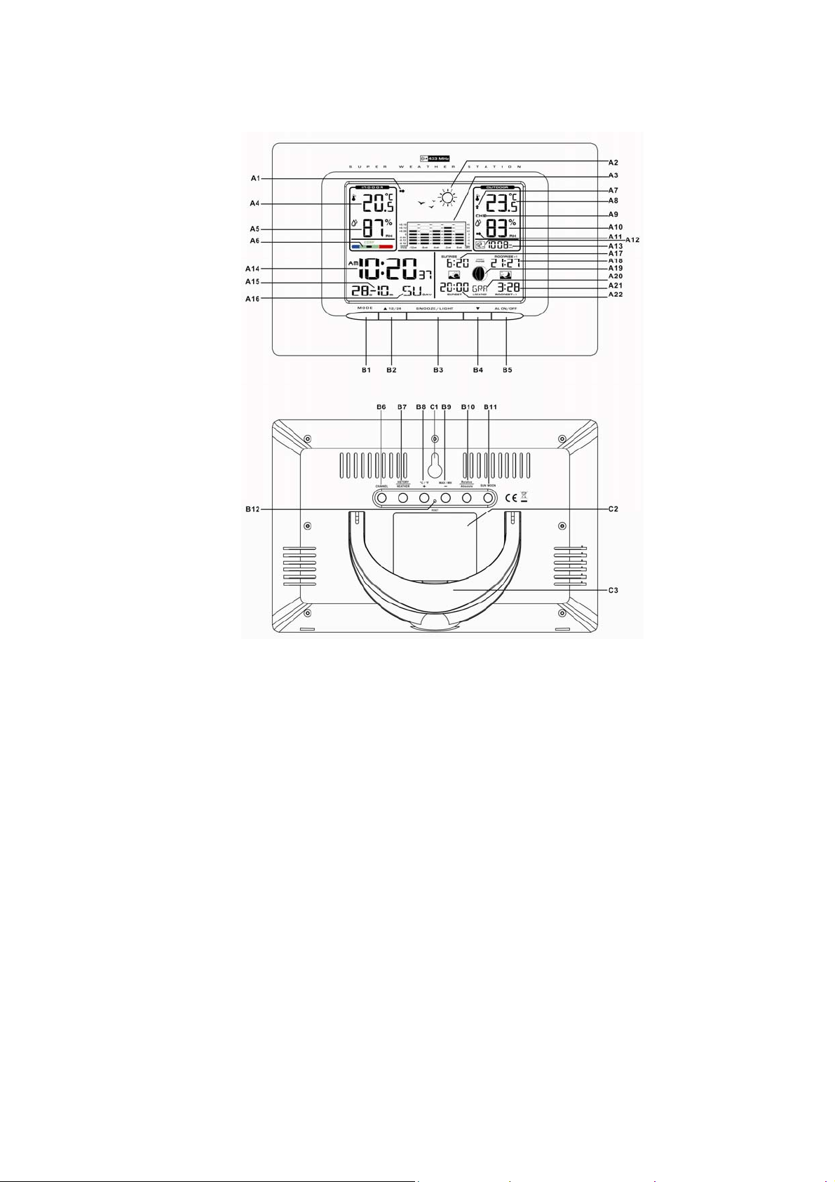
2. Main Unit Appearance
2.1 Part A- LCD
A1: Air Pressure Trend
A2: Weather Forecast
A3: Barometric Pressure Bar Graph
A4: Indoor Temperature
A5: Indoor Humidity
A6: Comfort Indicator Bar
A7: Outdoor Temperature Trend
A8: Outdoor Temperature
A9: Selected Channel
A10: Outdoor Humidity
A11: Outdoor Humidity Trend
A12: Barometric pressure of previous hour
A13: Absolute/Relative Barometric Pressure
Reading
A14: Time
A15: Date
A16: Day Of Week
A17: Sunrise Time
A18: Moonrise Time
A19: Moon phase
A20: Location
A21: Moonset Time
A22: Sunset Time
2.2 Part B- Buttons
B1: “MODE“ button
B2: “▲/ (12/24)” button
B3: “SNOOZE/LIGHT” button
B4: “▼” button
B5: “AL ON/OFF” button
B6: “CHANNEL” button
B7: “HISTORY/WEATHER” button
B8: “+/C/F” button
B9: “-/MAX/MIN” button
B10: “RELATIVE/ABSOLUT” button
B11: “SUN/MOON” button
B12: “RESET” button
2
Page 3
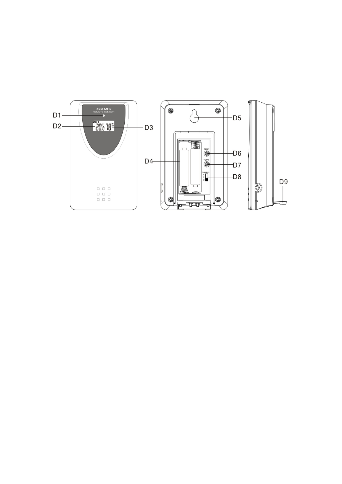
2.3 Part C- Structure
C1: Wall Mount Hole C2: Battery Cover
C3: Stand
3. Outdoor Thermo Sensor
D1: Transmission Indication LED
D2: Outdoor Temperature
display
D3: Outdoor Humidity display
D4: Battery Compartment
D5: Wall Mount Hole
D6: “RESET” button
D7: “C/F” button
D8: Channel Select Switch
D9: Stand
4. Getting Started:
4.1 Main Unit:
z Open main unit battery compartment cover [C2]
z Insert 3 x AA batteries observing polarity [ “+” and “ –“ marks]
z Replace main unit battery compartment cover [C2]
z Use a pin to press the RESET [B12] button on the rear of the main unit,
the main unit is now ready for use
4.2 Outdoor Thermo Sensor
z Batteries compartment (D4) of thermo sensor is locating behind the
back cover, unscrews the batteries cover to open.
z Insert 2 x AAA batteries observing polarity [ “+” and “–“ marks]
3
Page 4
5. Installation
5.1 Main Unit
The main unit can be placed onto any flat surface (C3), or wall
mounted by the hanging hole (C1) at the back of the unit.
5.2 Outdoor Thermo sensor
The remote sensor should be securely mounted onto a horizontal
surface.
Note: Transmissions between receiver and transmitter can reach up to
30m in open area. Open Area: there are no interfering obstacles
such as buildings, trees, vehicles, high voltage lines, etc.
6. Weather Forecast Function
6.1 Operation
z After Batteries inserted, or holding “WEATHER” button (B7) for 3
seconds, weather icon flash (A2) on the LCD. Enter the current
weather by pressing “-” (B9) or “+ “(B8) button. Press “WEATHER” (B7)
button to confirm the setting. The weather forecast may not be
accurate if the current weather entered is not correct.
z The current weather status should be entered again if the altitude of
the Main Unit is changed. (Barometric pressure is lower at higher
altitude location. Therefore, alti tude change will affect the weather
forecast). The weather station will start the first forecast at 6 hours
later after the current weather status is entered.
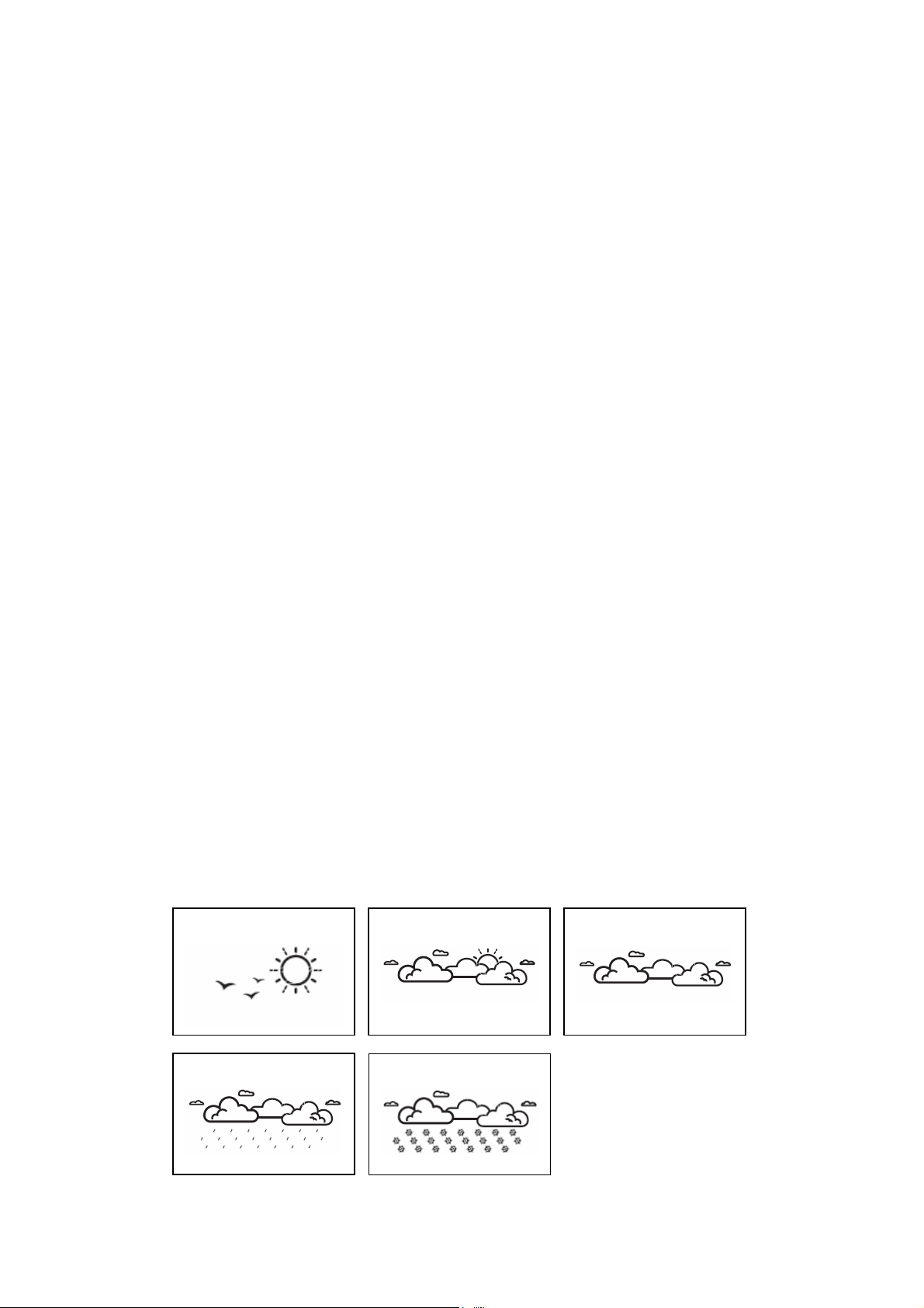
6.2 Weather Conditions
There are totally 5 different weather status animations in the weather
forecast.
Sunny
Rain
Slightly Cloudy
Freezing or Snow
Cloudy
4
Page 5
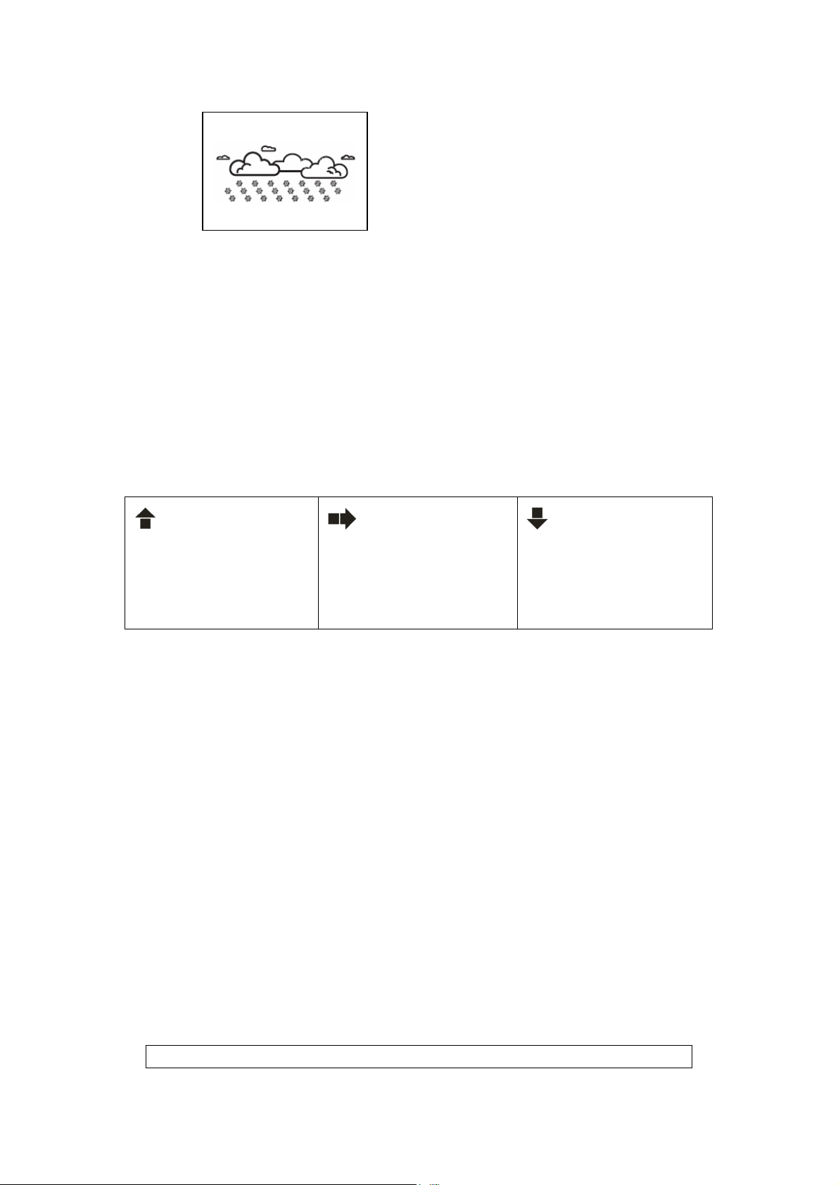
Note:
z “ “ is shown if the weather forecast is Rainy and
z Frost Alert: “ ” is shown if the outdoor temperature (any channel) is
z If there is any inconsistency of weather forecast between Local Weather
Freezing or Snow
outdoor
temperature (any channel) under
°
between -2
Station and this unit, the Local Weather Station's forecast should prevail.
The manufacture will not hold responsible for any trouble that may come
up due to wrong forecasting from this unit.
C ~ +3 °C
0°C.
7. Barometric Pressure Reading
7.1 Barometric Trend Pointer (A1)
The trend pointer displayed on the LCD (A1) indicates the trend of
the Barometric pressure.
Indicating the
barometric pressure
trend is rising
Indicating the
barometric pressure
trend is steady
Indicating the
barometric pressure
trend is falling
7.2 Absolute / Relative Air Pressure
z Press the “Absolute / Relative” button [B10] to toggle between
Absolute or Relative pressure display.
“ABS” is shown for Absolute Pressure; “REL” is shown for Relative
pressure
z Absolute pressure is the actual pressure measured by the Main Unit
z When viewing Relative pressure, hold “Absolute/Relative” button
[B10] for 3 seconds, press “-” (B9) or “+ “(B8) button to adjust, press
“Absolute / Relative” button [B10] to confirm.
Note: Check your local weather station for Sea Level pressure
information
7.3 Past Hour Air Pressure (History) Reading
z Press “HISTORY” button [B7] to view the past 12 hour’s Barometric
Pressure history. The hour is indicated on LCD [A12]
Press “HISTORY” button
5
Page 6
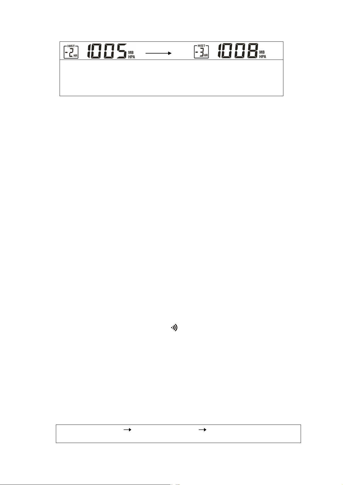
0 HR = Current Barometric Pressure Reading
-1HR = Barometric Pressure Reading in 1 hour ago
-2HR = Barometric Pressure Reading in 2 hour
ago ……..etc
z Hold “+” button [B8] for 3 seconds to select the unit for barometric
pressure meter in hPa, inHg or mmHG.
7.4 Barometric Pressure Bar Graph
The Barometric Pressure Reading at 0hr, –2hr,-4hr,-8hr,-12hr is recorded
and shown on Barometric Pressure Bar Graph [A3]. The Graph is
displayed in both hPa and inHg
8. Thermometer
8.1 RF Transmission Procedure:
z The main unit automatically starts receiving transmission from
outdoor thermo sensor for outdoor temperature after weather
condition setting.
z The thermo sensor unit will automatically transmit temperature to the
main unit after batteries inserted. For having more than one external
transmitter (Maximum3), select the Channel, CH1, CH2 or CH3 to
ensure each sensor is transmitting difference channel before
inserting batteries. The channel select switch (D8) is at the back of
the thermo sensor.
z If main unit failed to receive transmission from outdoor thermo
sensor in first 3 minutes after the batteries inserted (“- - . –”display on
the LCD), hold “Channel” button (B6) for 3 seconds to receive
transmission manually. RF icon “ ” flashes on the LCD
Note: “WEATHER/HISTROY” (B7), “+/C/F” (B8), “-/MAX/MIN“(B9),
“ABSOLUTE/RELATIVE” (B10) buttons will not function while scanning for
thermo sensor’s signal unless they are well received or stopped
manually.
8.2 Temperature & Humidity
(1) Outdoor Temperature--- Channel Selection
z Press “CHANNEL” button (B6) to view the 3 Channels’ temperature &
humidity. The sequence is shown as follow:
PRESS “CHANNEL” button PRESS “CHANNEL” button PRESS “CHANNEL”
button
6
Page 7
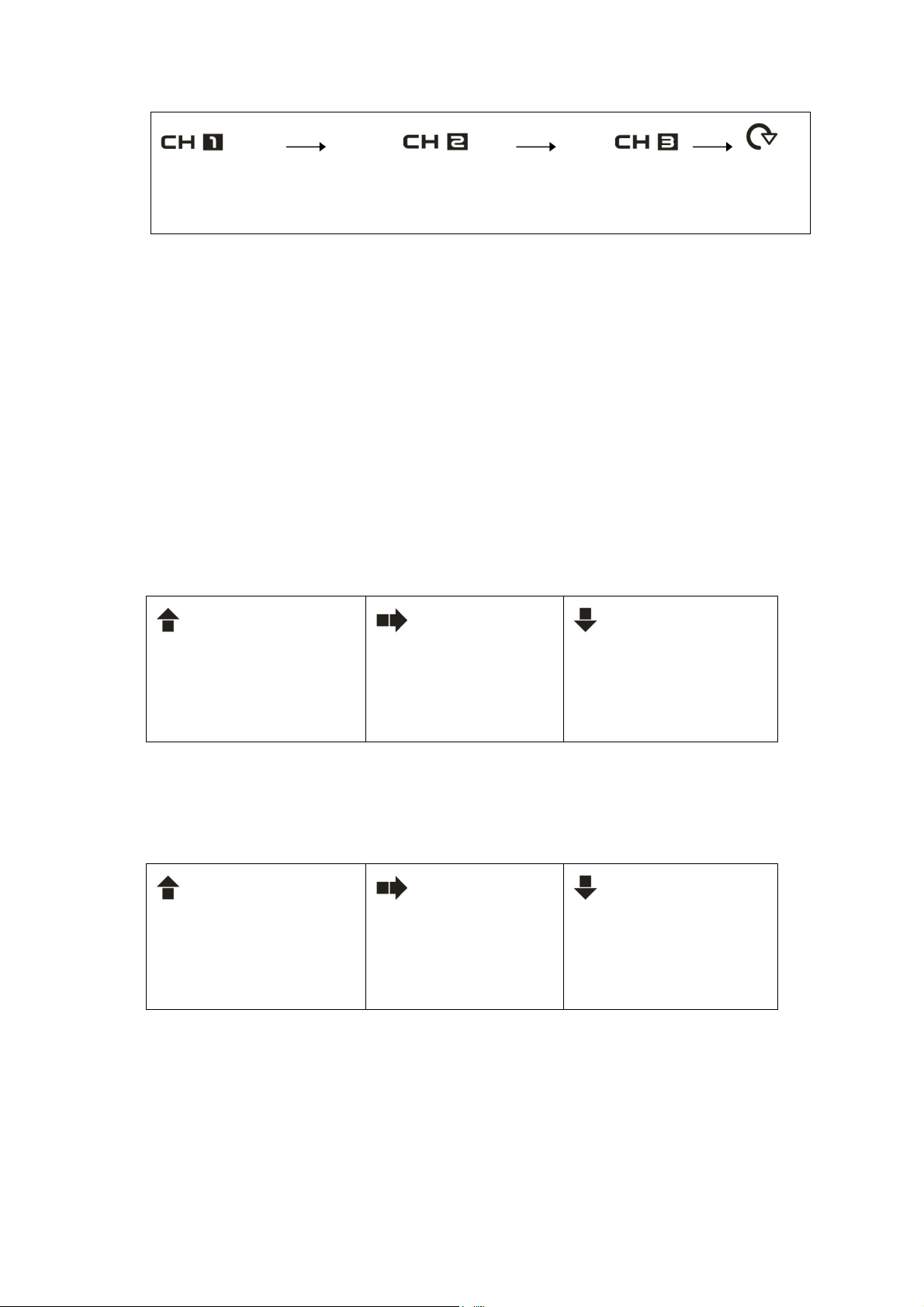
z When viewing the record on CHANNEL 1 or 2, or 3, hold “CHANNEL”
Display the three
channels
alternatively
button (B6) for 3 seconds to cancel the record on this channel
manually, and receive the transmission automatically again.
(2) Maximum / Minimum Temperature and Humidity
z Press “MAX/MIN” button (B9) to show the maximum recorded Indoor
/Outdoor Temperature and Humidity. “MAX” is shown on the LCD
z Press “MAX/MIN” button (B9) again to show the minimum recorded
Indoor/Outdoor Temperature and Humidity. “MIN” is shown on the
LCD.
(3) Outdoor Temperature Trend
z The trend pointer (A7) displayed on the LCD indicates the trend of
the outdoor temperature.
Indicating the outdoor
temp. is rising
Indicating the
outdoor temp. is
steady
Indicating the
outdoor temp. is
falling
(4) Outdoor Humidity Trend
z The trend pointer (A11) displayed on the LCD indicates the trend of
the outdoor humidity.
Indicating the outdoor
humidity is rising
Indicating the
outdoor humidity is
steady
Indicating the
outdoor humidity
down
(5) Celsius / Fahrenheit
z Press “°C /°F” button (B8) to select Indoor/Outdoor Temperature in
Celsius mode or Fahrenheit mode.
z If the temperature is out of the measurable range, LL.L (beyond the
minimum temperature) or HH.H (beyond the maximum temperature)
7
Page 8

will be shown on the LCD.
(6) Comfort Indicator Bar (A6) for the display of
pleasant/unpleasant climate, when the black dot in green zone means
pleasant climate.
9. Time and Alarm Setting
9.1 Manual Time Setting:
z Hold “MODE” button (B1) for 3 seconds to enter Clock/Calendar
setting mode.
z Press “▲” (B2) or “▼” (B4) button to adjust the setting and press
“MODE” button (B1) to confirm each setting.
(By keeping the “▲ ” (B2) or “▼ ” (B4) button pressed, could
accelerate the process and reach the desired value more quickly)
z The setting sequence is shown as follow: Hour, Minutes, Second, Year,
Month, Day, Country, City.
Note:
(1) Second adjusted to zero only.
(2) The Time Setting Mode will automatically exit in 15 seconds without
any adjustment.
(3) To turn DST (Daylight Savings Time) on or off, press and hold the “▲/
(12/24)" (B2) button. When “DST” is displayed above the minute
digits Daylight Savings Time is turned on. The sunrise/sunset times will
adjust accordingly.
9.2 12/24 Hour Display mode:
Press “12/24” button (B2) to select 12 or 24 hours mode.
9.3 Dual Daily Alarm Function:
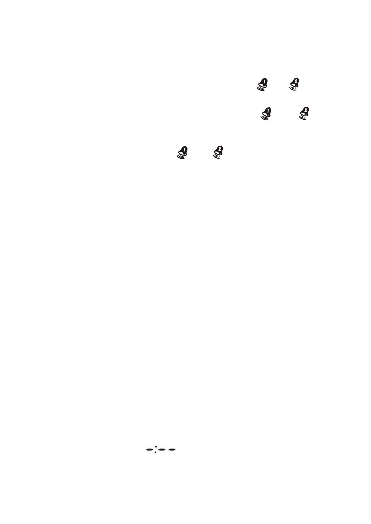
z Press “ MODE” button (B1) to select to view:
Time Alarm Time1 (Alarm Icon“ “flash on the LCD) Alarm
Time2 (Alarm Icon “
“flash on the LCD) Year
z When viewing Alarm Time 1 or Alarm Time 2, hold “MODE” button
(B1) for 3 seconds to enter that Alarm Time setting. Press “▲” (B2) or
8
Page 9
“▼” (B4) button to adjust the alarm time, press “MODE” button (B1)
to confirm the setting.
z When viewing Alarm Time 1 or Alarm Time 2, press “AL ON/OFF” (B5)
button to activate the alarm function. Alarm icon “ ” or “ ”will
be shown on the LCD. Press “AL ON/OFF” (B5) button again to
deactivate the alarm function, the alarm icon “ ” or “ ”
disappear from the display.
z When Alarming, press “SNOOZE / LIGHT” button (B3) to activate the
snooze alarm, alarm icon (“ ” or “ ”) flashes on LCD. The
alarm will snooze for 5 minutes, then it alarms again. This snooze
function can be enabled for maximum 7 times.
z Press any of “MODE” (B1) “▲/12/24” (B2), “▼” (B4), “AL ON/OFF” (B5),
OR “SUN/MOON” (B11) button to stop the snooze alarm. Otherwise,
the alarm signal sounds for about 2 minutes, then stops
automatically.
10. Sunrise/Sunset, Moonrise/Moonset Time Display Function
z After setting the Calendar, Local Country and home city in the Time
Setting Mode, the main unit calculates the Sunrise/Sunset
&Moonrise/Moonset. The Sunrise/Sunset & Moonrise/Moonset time
digits blink during the calculation.
z Press the “SUN/MOON” button (B11) to the display the total Sun
Hours of the select day.
z Hold the “SUN/MOON” button (B11) for 3 seconds to enter Sunrise/
Sunset, Moonrise/Moonset Time search mode, location digits (A20)
blink.
z Enter the “Country”, “City”, “Year”, “Month” and “Day” which you
would like to check. Press the “▲” [B2] or “▼“[B4] button to adjust
and press the “SUN/MOON” button (B11) to confirm setting.
z The Sunrise / Sunset, Moonrise/Moonset time digits blink during the
calculation. After calculation, Sunrise/Sunset and
Moonset/Moonrise time is shown.
z If moonrise or moonset occurs at next day, then “MOONRISE +1” or
“MOONSET +1” will be disp layed. If there is no moonrise or moonset
occur on someday, “
“ will be displayed on the LCD
Note: The Sunrise/Sunset and Moonrise/ Moonset time display is just
for reference only. For exact Sunrise/Sunset and Moonrise/Moonset
9
Page 10
time, please refer to your Local Weather Station
11. Moon Phase Display
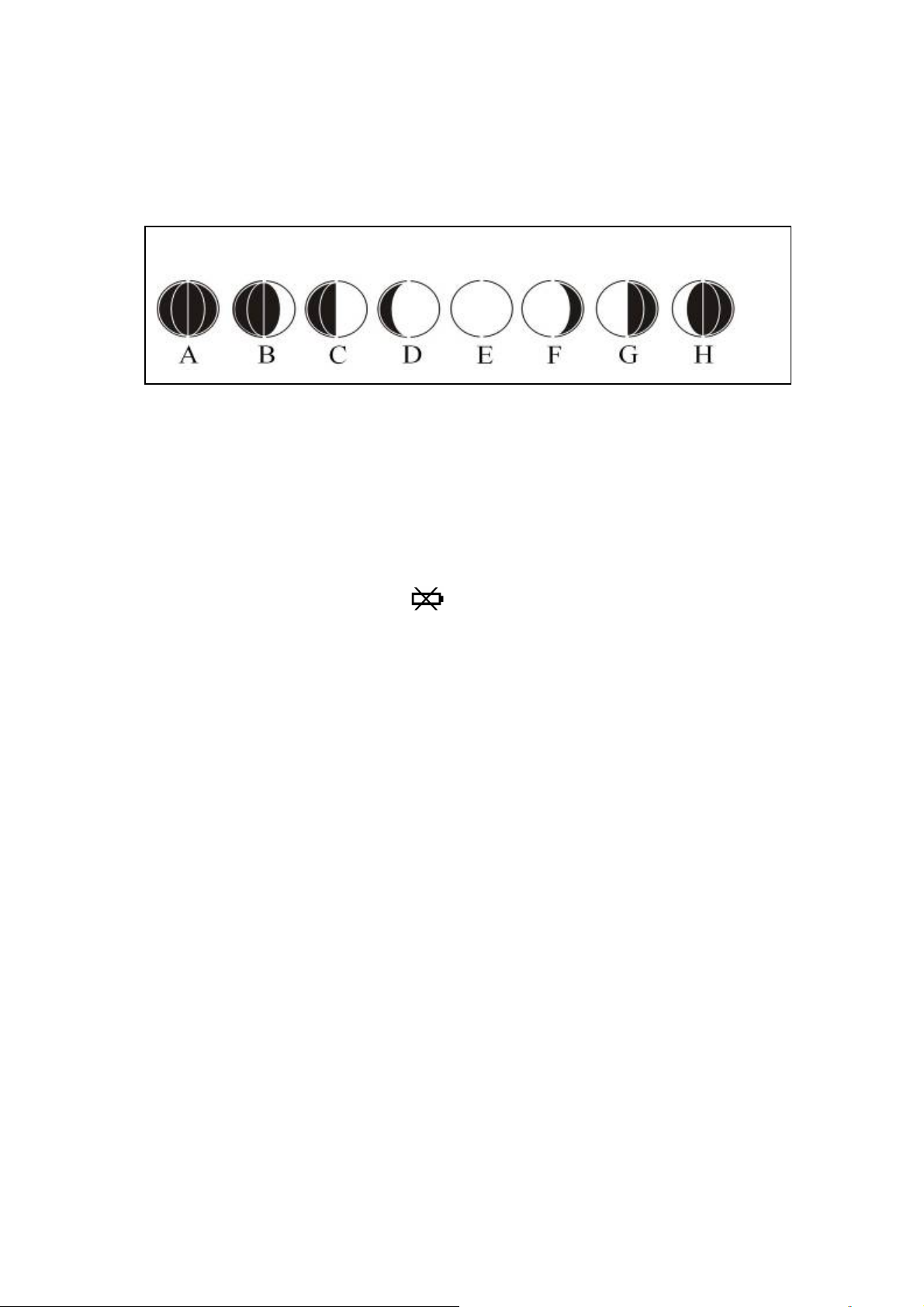
The Moon Phase (A19) of each day is shown on the LCD.
A: New Moon B: Waxing Crescent
C: First Quarter
D: Waxing Gibbous E: Full Moon F: Waning
Gibbous
G: Last Quarter H: Waning Crescent
12. Low battery indication:
The low battery icon “ ”will appear at particular channel
indicating that thermo sensor unit of the channel is in low battery
status. The batteries should be replaced.
13. Backlight
Press “SNOOZE/LIGHT” button (B3), back light states for 3 seconds.
14. Precautions
z Use a pin to press the reset button (B12) if the Unit does not work properly.
z Avoid placing the clock near interference sources/metal frames such as
computer or TV sets.
z The clock loses its time information when the battery is removed.
z Do not expose it to direct sunlight, heavy heat, cold, high humidity or wet
areas
z The outdoor sensor must not be set up and installed under water. Set it up in
away direct sunlight and Rain
z Never clean the device using abrasive or corrosive materials or products.
Abrasive cleaning agents may scratch plastic parts and corrode electronic
10
Page 11
circuits
z If there is any inconsistency of weather forecast between Local Weather
Station and this unit, the Local Weather Station's forecast should prevail. The
manufacturer will not take responsible for incorrect forecasting from this unit
15. Specifications
Indoor Data:
Temperature range: 0 to 50°C [+32 to +122°F]
Temperature Units
Humidity Range:
°C or °F [switchable]
20% to 99%
Air Pressure Range: 850 – 1050 hPa
Air Pressure Units
Weather Forecast:
mb/hPa, inHg & mmHG [switchable]
5 icons [sunny, slightly cloudy,
cloudy, rainy & snow]
Outdoor Data:
Transmission distance:
(open area)
30m @ 433MHz
Temperature range: -20°C to 50°C [-4 to +122°F]
Mount: wall / table
Main Unit Dimensions:
Thermo Sensor
W230 x h150 x d30 mm
w62 x h101 x d24 mm
Battery Requirements:
Base Station [indoor]: 3 x AA batteries
Sensors [outdoor]: 2 x AAA batteries
Countries and Cities: there are 3 countries can be chosen from the Time Setting
Mode. They are listed in the following table.
USA USA Iowa IA Mississippi MS
Alaska AK Waterloo ALO Greenwood GWO
Juneau JNU Des Moines DSM Huntsville HUV
Alabama AL Davenport DVN Jackson JAN
Birmingham BHM Sioux City SUX Tupelo TUP
Gadsden GAD Idaho ID Montana MT
Montgomery MGM Boise BOI Billings BIL
Mobile MOB Gibbonsville GIB Ft. Peck FTP
11
Page 12
Arkansas AR Pocatello PIH Great Falls GFT
Fort Smith FSM Sandpoint SZT Helena HLN
Little Rock LIT Illinois IL Sidney SDY
Texarkana TXK Champaign CMI Whitefish WTF
Arizona AZ Chicago ORD North Carolina NC
Flagstaff FLG Springfield SPI Asheville AVL
Phoenix PHX Indiana IN Charlotte CLT
Tucson TUS Evansville EVV Fayetteville FAY
Yuma YUM Terre Haute HUF Wilmington ILM
California CA Indianapolis IND Winston-Salem INT
Bakersfield BFL South Bend SBN Williamston MCZ
Blythe BLH Kansas KS Raleigh RDU
Eureka EKA Dodge City DDC North Dakota ND
Fresno FAT Wichita K32 Bismarck BIS
Fort Bragg FTB Kansas City KCK Bowbells BWB
Los Angeles LAX Wakeeney OH1 Fargo FAR
Redding ROD Topeka TOP Grand Forks GFK
Sacramento SAC Kentucky KY Nebraska NE
San Diego SAN Frankfort FFT Grand Island GRI
San Bernardino SBD Lexington LEX Lincoin LNK
San Francisco SFO Louisville LOU Omaha OMA
Colorado CO Louisiana LA Sidney SNY
Denver DEN Baton Rouge BTR Valentine VTN
Durango DRO Lake Charles CWF New Hampshire NH
Fort Collins FNL Natchitoches IER Concord CON
Grand Junction GJT New Orleans NEW New Jersey NJ
Burlington ITR Shreveport SHV Newark EWR
Pueblo PUB Massachusetts MA Trenton TTN
Connecticut CT Boston BOS New Mexico NM
Hartford HFD Maryland MD Albuquerque ABQ
District of Columbia DC Baltimore BWI Magdalene MAG
Washington DCA Maine ME Roswell ROW
Delaware DE Augusta AUG Raton RTN
Dover 0N5 Bangor BGR Santa Fe SAF
Florida FLG Caribou CAR Nevada NV
Key West EYW Portland PWM Austin AIN
Jacksonville JAX Michigan MIA Carson City CXP
Miami MIA Kalamazoo AZO Ely ELY
Orlando ORL Detroit DET Las Vegas LAS
Pensacola PNS Flint FNT Wells LWL
12
Page 13
Tallahassee TLH Lansing LAN Reno RNO
Tampa TPA Rogers City PZQ New York NY
Georgia GA Marquette SAW Albany ALB
Albany ABY Traverse City TVC Buffalo BUF
Augusta AGS Minnesota MN New York City JFK
Atlanta ATL Albert Lea AEL Lake Placid LKP
Columbus CSG Bemidji BJI Syracuse SYR
Macon MAC Duluth DLH Ohio OH
Savanna SAV Grand Protage GPO Cleveland CLE
Hawaii HI International Falls INL Columbus CMH
Honolulu HNL St. Paul STP Cincinnati ISZ
Hilo ITO Missouri MO Toledo TOL
Kahului OGC Jefferson City JEF Youngstown YNG
Waimea WAI Kansas City MKC Oklahoma OK
Memphis MPH Boise City 17K
Poplar Bluff POF Lawton LAW
Springfield SGF Oklahoma City
St. Louis STL Tulsa TUL
OKC
Oregon OR Utah UT West Virginia WV
Burns BNO Saline SAL Charleston CRW
Eugene EUG St. George SGU Wheeling HLG
Medford MFR Salt Lake City SLC Wyoming WY
Portland PDX Thompson TSN Buffalo BYG
Salem SLE Virginia VA Casper CPR
Pennsylvania PA Vienna DON Cheyenne CYS
Harrisburg CXY Lynchburg LYH Little America LAA
Philadelphia PHL Norfolk ORF West Yellowstone WYE
13
Page 14
Pittsburgh PIT Richmond RIC Canada CAN
Scranton SCR Roanoke ROA Calgary CAL
Puerto Rico PR Vermont VT Charlotte Town CHT
San Juan SJU Burlington BTV Edmonton EDM
Rhode Island RI Montpelier MPR Fredericton FRE
Providence PVD Washington WA Halifax HAL
South Carolina SCR Aberdeen ABE Montreal MON
Charleston CHS Walla Walla ALW Ottawa OTT
Columbia CUB Kettle Falls KTF Quebec QUE
Greenville GMU Mount Vernon MVN Regina REG
South Dakota SD Olympia OLM Sudbury SUD
Sioux Falls FSD Seattle SEA Thunder Bay THU
Pierre PIR Spokane SFF Toronto TOR
Rapid City RAP Tonasket TON Vancouver VAN
Tennessee TN Yakima YKM Winnipeg WIN
Nashville BNA Wisconsin WI Mexico MEX
Chattanooga CHA Wausau AUW Chihuahua CHH
Knoxville DKX Green Bay GRB Durango DUR
Memphis MFR La Crosse LSE Guadalupe GUA
Texas TX Madison MSN Hermosillo HER
Abilene ABI Milwaukee MWC Mexico City MEC
Amarillo AMA Spooner SSQ
Austin AUS
Brownsville BRO
Dallas/Ft. Worth DFW
El Paso ELP
Houston HOU
Laredo LRD
Odessa ODO
San Antonio SAT
14
Page 15

FCC STATEMENT
1. This device complies with Part 15 of the FCC Rules. Operati on is su bject to the
following two conditions:
(1) This device may not cause harmful interference.
(2) This device must accept any interference received, including interference that
may cause undesired operation.
2. Changes or modifications not expressly approved by the party responsible for
compliance could void the user's authority to operate the equipment.
NOTE: This equipment has been tested and found to comply w i th the limits for a
Class B digital device, pursuant to Part 15 of the FCC Rules. These limits are
designed to provide reasonable protection against harmful interferen ce in a
residential installation.
This equipment generates uses and can radiate radio frequency energy and, if
not installed and used in accordance with the instructions, may cause harmful
interference to radio communications. However, there is no guarantee that
interference will not occur in a particular installation. If this equipment does cause
harmful interference to radio or television reception, which can be determined by
turning the equipment off and on, the user is encouraged to t ry to correct the
interference by one or more of the following measures:
Reorient or relocate the receiving antenna.
Increase the separation between the equipment and receiver.
Connect the equipment into an outlet on a circuit different from that to which
the receiver is connected.
Consult the dealer or an experienced radio/TV technician for help.
15
 Loading...