

Page 1
WEATHERMASTER
48P2,P3,P4,P5030-100
Single Package Gas Heating and Electric Cooling Units
with Direct Spark Ignition and COMFORTLINK™ Controls
Installation Instructions
®
CONTENTS
Page
GENERAL . . . . . . . . . . . . . . . . . . . . . . . . . . . . . . . . . . . . . . . . 1
SAFETY CONSIDERATIONS . . . . . . . . . . . . . . . . . . . . .1,2
INSTALLATION . . . . . . . . . . . . . . . . . . . . . . . . . . . . . . . . 2-68
Step 1 — Jobsite Survey . . . . . . . . . . . . . . . . . . . . . . . . . 2
Step 2 — Place Unit . . . . . . . . . . . . . . . . . . . . . . . . . . . . . . 2
Step 3 — Roof Mount Unit. . . . . . . . . . . . . . . . . . . . . . . . 2
Step 4 — Slab Mount Unit . . . . . . . . . . . . . . . . . . . . . . . . 2
Step 5 — Install Curb Gasketing. . . . . . . . . . . . . . . . . . 2
Step 6 — Install Field-Fabricated Ductwork . . . . . . 2
Step 7 — Rig Unit . . . . . . . . . . . . . . . . . . . . . . . . . . . . . . . . 2
Step 8 — Connect Condensate Drain. . . . . . . . . . . . 16
Step 9 — Install Outdoor Hoods (Units without
Optional High-Capacity Power Exhaust). . . . . . 32
• UNIT SIZES 030-050
• UNIT SIZES 055-100
Step 10 — Install Economizer Hoods (Units with
Optional High-Capacity Power Exhaust). . . . . . 33
• INSTALL SMALL HOODS
• INSTALL LARGE HOODS
Step 11 — Route Field Wiring . . . . . . . . . . . . . . . . . . . 35
• UNIT SIZES 030-060
• UNIT SIZES 070-100
Step 12 — Make Field Electrical Connections . . . 35
•POWER WIRING
Step 13 — Connect Air Pressure Tubing . . . . . . . . 58
• VARIABLE FRQUENCY DRIVE
• MODULATING POWER EXHAUST
• RETURN FAN POWER EXHAUST
Step 14 — Remove Supply-Fan Shipping
Brackets . . . . . . . . . . . . . . . . . . . . . . . . . . . . . . . . . . . . . 60
Step 15 — Remove Optional Return-Fan
Shipping Brackets . . . . . . . . . . . . . . . . . . . . . . . . . . . 60
Step 16 — Connect Gas Piping. . . . . . . . . . . . . . . . . . 61
Step 17 — Configure Optional Staged Gas
Control. . . . . . . . . . . . . . . . . . . . . . . . . . . . . . . . . . . . . . . 61
Step 18 — Install Flue/Inlet Hoods and Baffles . . 62
Step 19 — Install Supply-Air Thermistors
(Staged and Modulating Gas Units Only) . . . . . 62
Step 20 — Install Optional Motormaster
Control. . . . . . . . . . . . . . . . . . . . . . . . . . . . . . . . . . . . . . . 66
Step 21 — Install Unit Accessories. . . . . . . . . . . . . . 68
CONTROLS INSTALLATION . . . . . . . . . . . . . . . . . . 68-76
Constant Volume Units. . . . . . . . . . . . . . . . . . . . . . . . . . 68
• CONTROL WIRING
Variable Air Volume (VAV) Units . . . . . . . . . . . . . . . . . 68
Optional and Accessory Control Wiring . . . . . . . . . 68
Carrier Comfort Network
Optional UPC Open Installation . . . . . . . . . . . . . . . . . 74
Smoke Control Modes. . . . . . . . . . . . . . . . . . . . . . . . . . . 74
®
(CCN) Interface. . . . . . . 73
®
V
GENERAL
This installation instruction contains basic unit installation
information, including installation of thermostats and remote
temperature sensors.
For additional information and service instructions, refer to
the Controls and Troubleshooting literature.
A factory-installed optional integral economizer and high-
capacity power exhaust is available on size 075-100 units.
A factory-installed optional return fan is available on size
075-100 units.
The staged gas control (SGC) option adds the capability to
control the rooftop unit’s gas heating system to a specified
supply-air temperature set point for purposes of tempering a
cool mixed-air condition.
SAFETY CONSIDERATIONS
Installation and servicing of air-conditioning equipment can
be hazardous due to system pressure and electrical components. Only trained and qualified service personnel should
install, repair, or service air-conditioning equipment.
Untrained personnel can perform basic maintenance functions of cleaning coils and filters and replacing filters. All
other operations should be performed by trained service personnel. When working on air-conditioning equipment, observe
precautions in the literature, tags and labels attached to the unit,
and other safety precautions that may apply.
Follow all safety codes, including ANSI (American National Standards Institute) Z223.1. Wear safety glasses and work
gloves. Use quenching cloth for unbrazing operations. Have
fire extinguisher available for all brazing operations.
WARNING
Before performing service or maintenance operations on
unit, turn off main power switch to unit. Electrical shock
could cause personal injury.
FOR YOUR SAFETY
WHAT TO DO IF YOU SMELL GAS
Do not try to light any appliance. Do not touch any electrical switch; do not use any phone in your building. Immediately call your gas supplier from a neighbor’s phone.
Follow the gas supplier’s instructions. If you cannot reach
your gas supplier, call the fire department.
FOR YOUR SAFETY
Do not store or use gasoline or other flammable vapors and
liquids in the vicinity of this or any other appliance.
WARNING
Improper installation, adjustment, alteration, service, or
maintenance can cause injury or property damage. Refer to
this manual. For assistance or additional information, consult a qualified installer, service agency, or the gas supplier.
Manufacturer reserves the right to discontinue, or change at any time, specifications or designs without notice and without incurring obligations.
Catalog No. 04-53480079-01 Printed in U.S.A. Form 48P-4SI Pg 1 11-10 Replaces: 48P-3SI
Page 2
CAUTION
Disconnect gas piping from units when leak testing at pressures greater than 0.5 psig. Pressures greater than 0.5 psig
will cause gas valve damage resulting in a hazardous
condition. If gas valve is subjected to pressure greater than
0.5 psig, it must be replaced. When pressure testing fieldsupplied gas piping at pressures of 0.5 psig or less, the unit
connected to such piping must be isolated by manually
closing the gas valve.
INSTALLATION
Step 1 — Perform Jobsite Survey —
the following checks before installation.
1. Consult local building codes and the NEC (National
Electrical Code) (ANSI/NFPA [American National Standards Institute/National Fire Protection Association] 70)
for special installation requirements.
2. Determine unit location (from project plans) or select unit
location.
3. Check for possible overhead obstructions which may interfere with unit lifting or rigging.
Complete
CAUTION
Do not lift unit with forklift truck. Move unit with overhead rigging only.
Step 2 — Place Unit — Inspect unit for transportation
damage. File claim with transportation agency.
Provide clearance around and above unit for airflow, safety,
and service access. Do not restrict top (area above condenser
fans) in any way. Allow at least 6 ft on all sides for rated performance, code compliance, and service. On units equipped with
power exhaust option, high velocity air is exhausted out the
hood. Unit should be positioned with at least 10 ft clearance between the exhaust hood and any obstruction.
Check unit dimensional drawings for unit arrangement and
minimum performance and service clearances.
Do not install unit in an indoor location. Do not locate air inlets near exhaust vents or other sources of contaminated air.
Although unit is weatherproof, guard against water from
higher level runoff and overhangs.
Level by using unit frame as a reference. Physical data is
shown in Tables 1A-9.
Step 3 — Roof Mount Unit — Check building codes
for weight distribution requirements. Unit weight is shown in
Tables 1A-1C and 5. Unit may be mounted on class A, B, or C
roofing material.
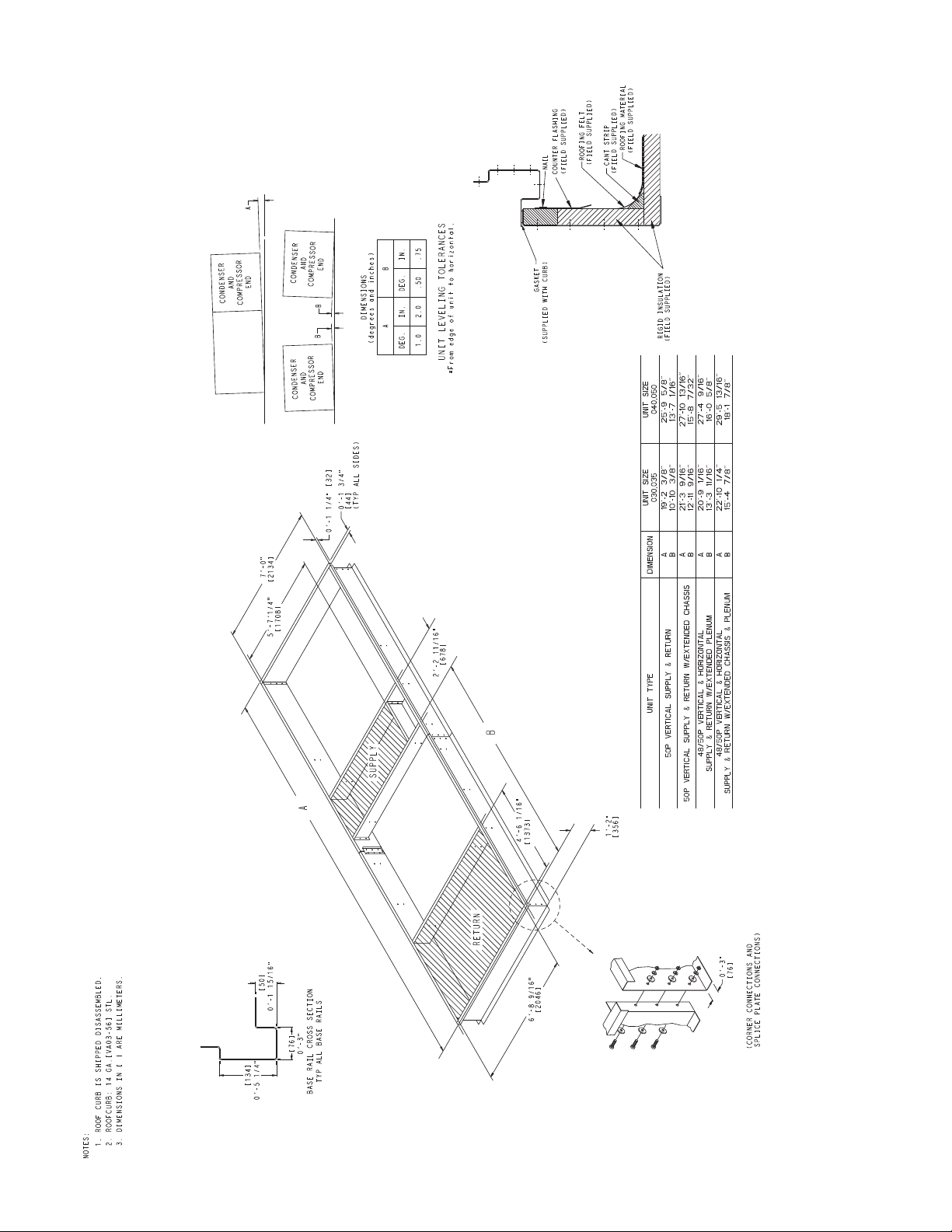
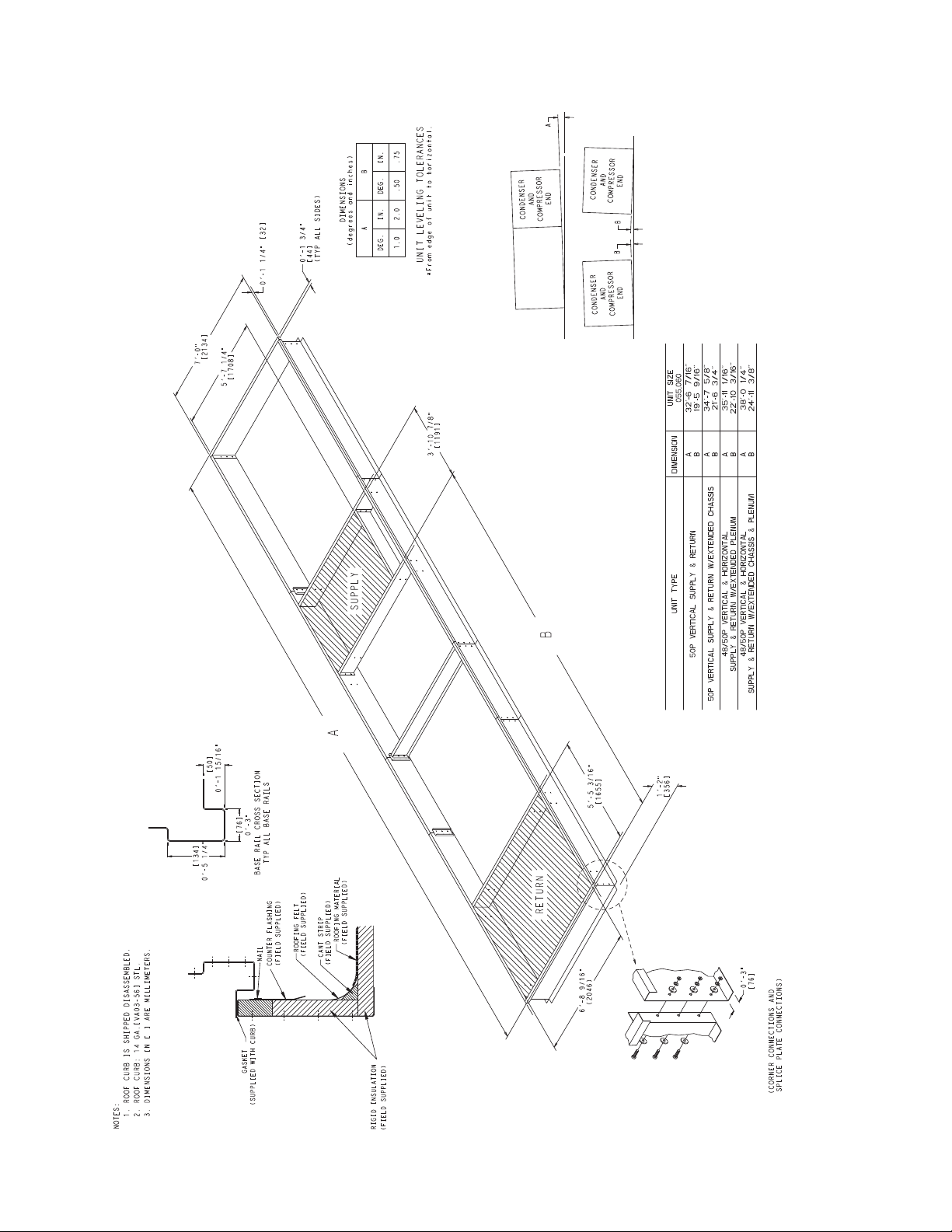
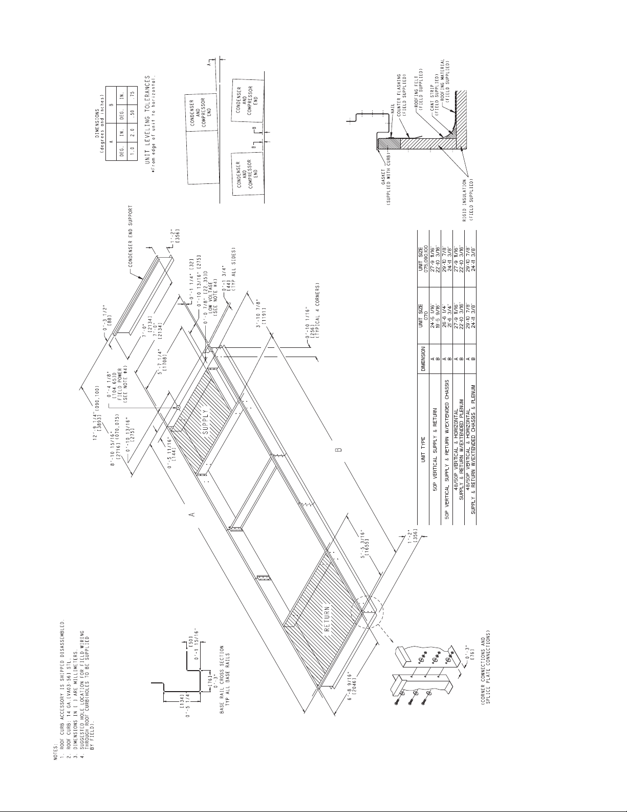
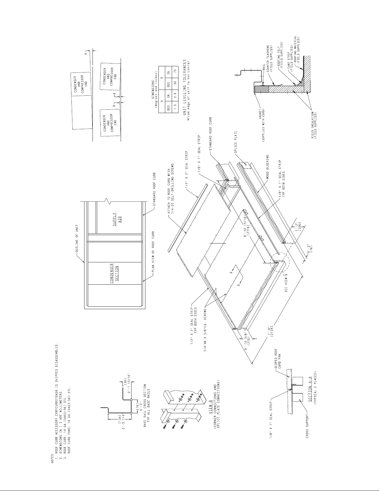
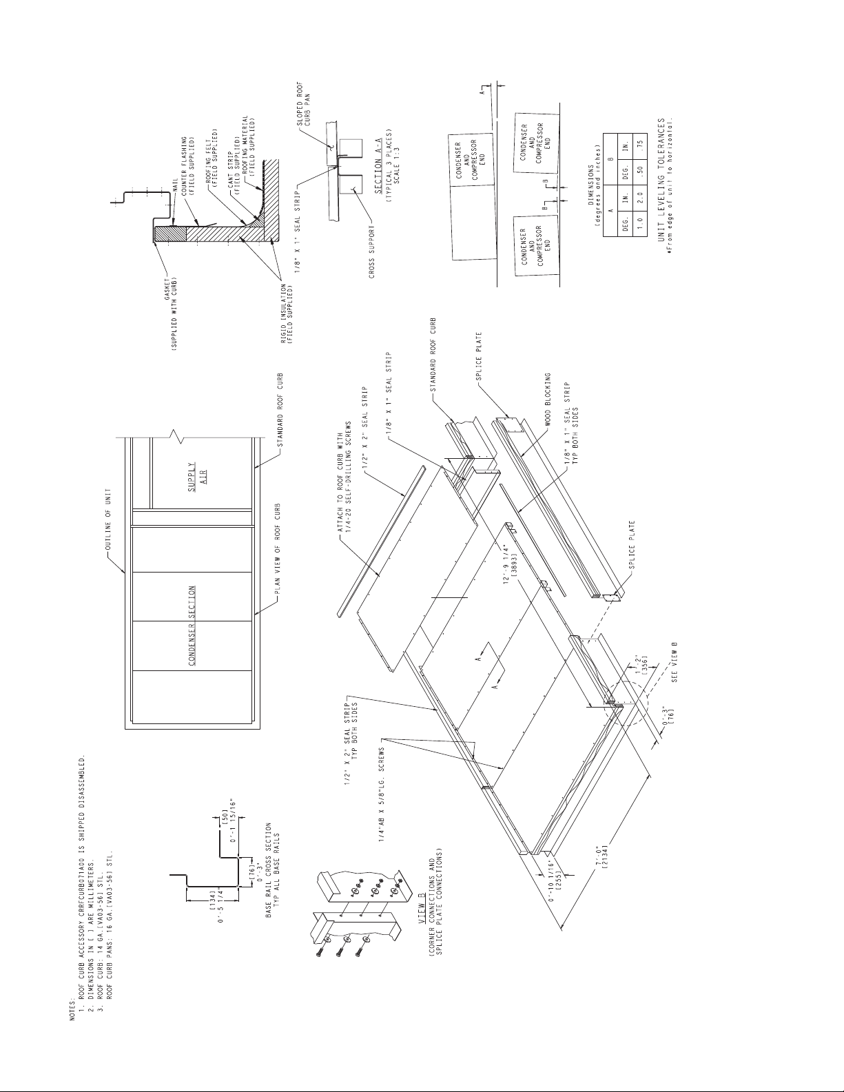
ROOF CURB — Assemble and install roof curb as described
in instructions shipped with the accessory. Accessory roof curb
and information required to field fabricate a roof curb is shown
in Fig. 1-5. Install insulation, cant strips, roofing and counter
flashing as required. For unit condensate drain to function
properly, curb must be level or within tolerances shown in
Fig. 1-5.
STEEL BEAMS — If roof curb is not used, support unit with
steel beams along its entire length and then support steel as required. As a minimum, unit must be supported across its width
at each lifting lug location.
Step 4 — Slab Mount Unit — Provide a level con-
crete slab that extends beyond unit cabinet at least 6 inches.
Make a slab 8 in. thick with 4 in. above grade. Use gravel
apron in front of condenser coil air inlet to prevent grass and
foliage from obstructing airflow. Ensure that slab is of
sufficient height to allow for condensate trap of 4 in. on sizes
030-070 or 7 in. on sizes 075-100.
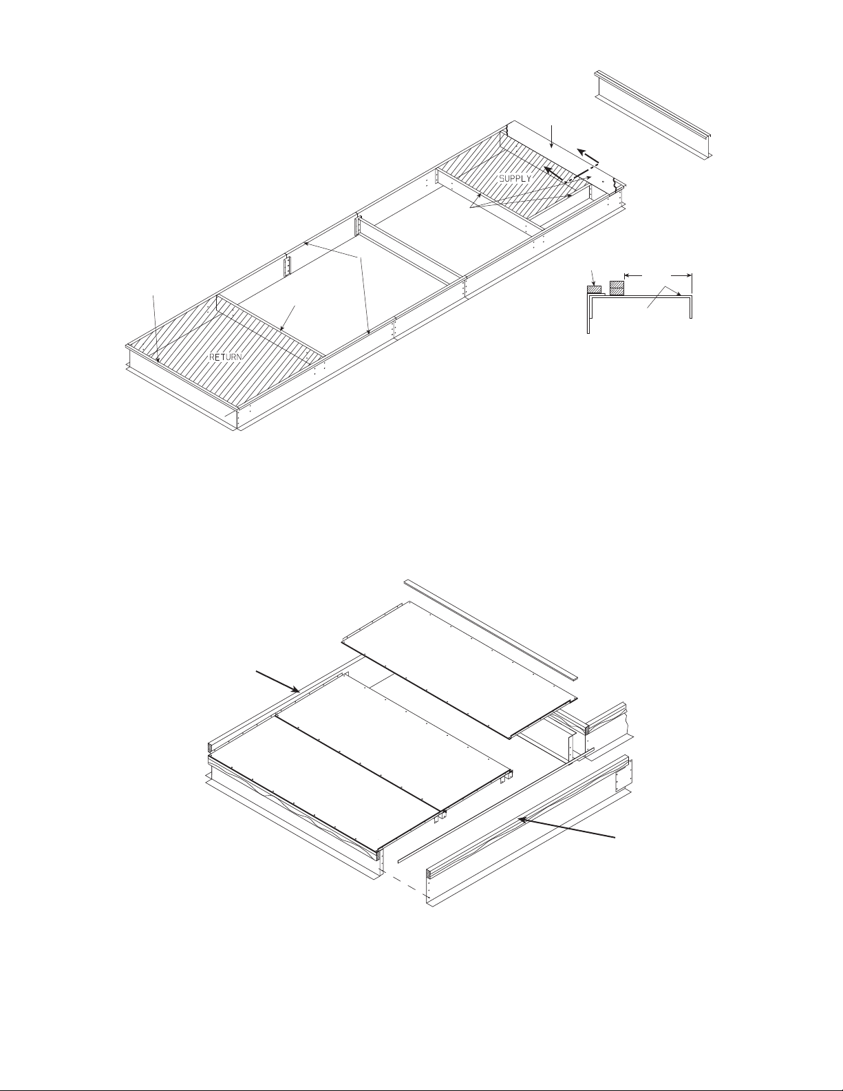
Step 5 — Install Curb Gasketing
SIZE 030-060 UNITS — After ductwork has been connected
to the roof curb, attach adhesive-backed gasketing on all end
rails, cross rails, and duct rails. Be sure all joints and corners of
gasket are square and flush to prevent possible water leaks.
Follow all applicable building codes.
SIZE 070-100 UNITS — After ductwork has been connected
to the roof curb, apply gasket material (
wide neoprene) where indicated.
Single-Thickness Gasketing (See Fig. 6-8 for Item Numbers) — Apply gasketing in the following places:
1. Along both side rails (1) — 2 places, full length
2. Along return air end rail (2) — 1 place
3. Around return air internal duct flange (3) — 1 or 2 places
4. Around supply air internal duct flanges (4) — 3 places
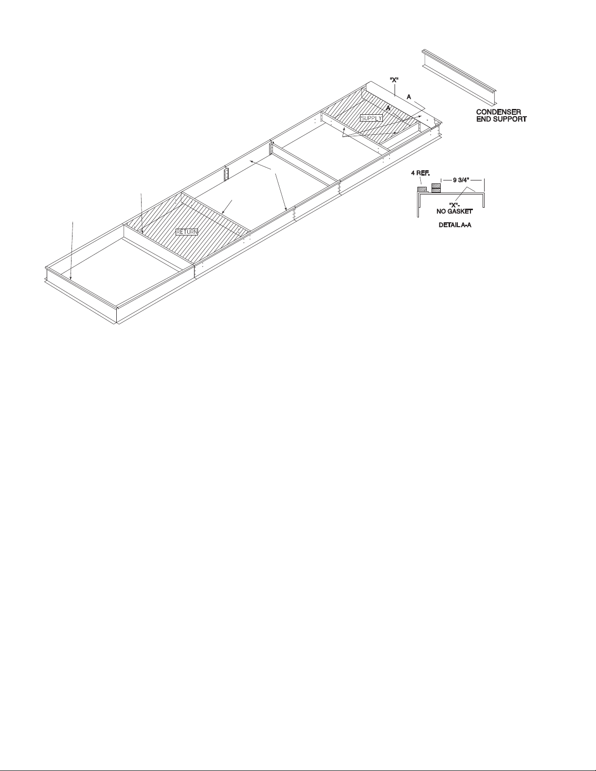
Double-Thickness Gasketing (See Fig. 6 and 8 and Detail
A-A) — Locate a line 93/4-in. from the supply air end of the
accessory curb. Apply a double-thickness of gasket material
along line per detail A-A.
NOTE: Do not apply gasket material along the outside edge of
the curb (area “X”). This pan area of the curb extends out
beneath the end of the unit’s air handler section; applying gasket here develops a potential water trap area on top of the curb.
Condenser Section Roof Curb (See Fig. 7)
thickness gasket along both side rails (5).
1
/2-in. thick x 11/2-in.
— Apply single-
Step 6 — Install Field-Fabricated Ductwork
WARNING
For vertical supply and return units, tools or parts could
drop into ductwork and cause an injury. Install a 90-degree
elbow in the supply and return ductwork between the unit
and the conditioned space. If a 90-degree elbow cannot be
installed, then a grille of sufficient strength and density
should be installed to prevent objects from falling into the
conditioned space. Failure to follow these instructions
could result in personal injury or property damage due to
falling objects.
The 48P2,P3 units are designed for vertical supply/return
only. Field-fabricated ductwork must be attached to the roof
curb, or to the support steel, prior to the final rigging and installation of the unit. Supply and return duct dimensions are shown
in Fig. 1-3.
To attach ductwork to roof curb, insert duct approximately 10
to 11 in. up into roof curb. Connect ductwork to 14-gage roof
curb material with sheet metal screws driven from inside the duct.
Secure all ducts to the building structure, using flexible duct
connectors between roof curbs and ducts as required. Ducts
passing through an unconditioned space must be insulated and
covered with a vapor barrier. Outlet grilles must not lie directly
below unit discharge.
Design supply duct strong enough to handle expected static
pressures.
Step 7 — Rig Unit — Do not drop unit; keep upright.
Use spreader bars over unit to prevent sling or cable damage.
Sheets of plywood placed along the condenser coils will provide additional protection. All lifting lugs MUST be used when
lifting unit. Level by using unit frame as a reference. See Fig. 9
and 10 for information. Unit and accessory weights are shown
in Tables 1A-1C and 5. Weight distribution and center of gravity can be found in Fig. 11.
2
Page 3
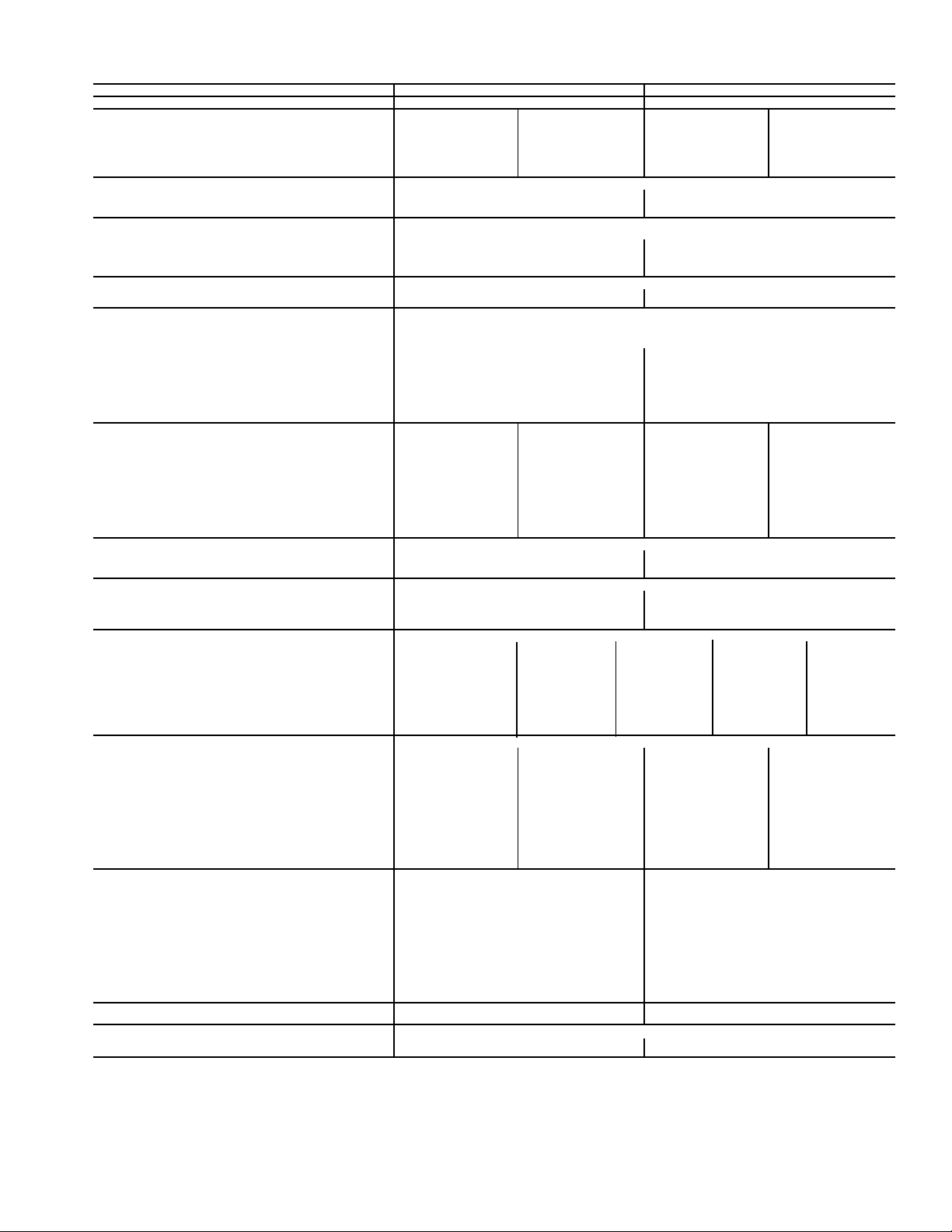
Table 1A — Physical Data 48P2,P3,P4,P5030-050
BASE UNIT 48P2,P3,P4,P5030 48P2,P3,P4,P5035
NOMINAL CAPACITY (tons) 30 35
OPERATING WEIGHT (lb) Standard Chassis Extended Chassis Standard Chassis Extended Chassis
Base Unit
Low Heat 5310 5810 5410 5910
High Heat 5440 5940 5540 6040
With Economizer
Low Heat 5610 6110 5710 6210
High Heat 5740 6240 5840 6340
COMPRESSORS Scroll
Quantity...Type 1...ZP154/1...ZP154 1...ZP182/1...ZP182
Oil Charge (oz) per Compressor 110 110
Number of Refrigerant Circuits 22
REFRIGERANT R-410A
Operating Charge (lb), Ckt 1/Ckt 2
Standard Evaporator Coil 15.4/14.8 18.4/17.6
Standard Evaporator with Humidi-MiZer® 15.4/24.9 18.4/27.7
Alternate High-Capacity Evaporator Coil 18.4/17.7 N/A
Alternate High-Capacity Evaporator with Humidi-MiZer 18.4/27.8 N/A
CONDENSER COILS Aluminum Novation® Heat Exchanger with Microchannel Coils
Quantity 11
Total Face Area (sq ft) 33.3 33.3
EVAPORATOR COILS
Quantity 1
Total Face Area (sq ft) 32.1
Refrigerant Feed Device...No. per Circuit TXV...1
Standard Evaporator Coils
Rows...Fins/in. 3...15.0 4...15.0
Fin Type Double Wavy Double Wavy
Tube Type Cross Hatched Cross Hatched
Alternate, High-Capacity Evaporator Coils
Rows...Fins/in. 4...15.0 N/A
Fin Type Double Wavy N/A
Tube Type Cross Hatched N/A
HEATING SECTION Low Heat High Heat Low Heat High Heat
Number of Heat Exchangers 714714
Input (MBtuh) 325 650 325 650
Output (MBtuh) (Vertical/Horizontal) 263/260 527/520 263/260 527/520
Temperature Rise Range (F) 10-40 25-55 10-40 25-55
Efficiency (%) (Vertical/Horizontal) 81/80 81/80 81/80 81/80
Burner Orifice Diameter
Quantity (in. ...drill no.) 7 (.1285...30) 14 (.1285...30) 7 (.1258...30) 14 (.1258...30)
Manifold Pressure (in. wg) 3.5 3.5 3.5 3.5
Line Pressure (in. wg) (min...max) 5.0...13.0 5.0...13.0 5.0...13.0 5.0...13.0
Firing Stages 2222
Number of Gas Valves 1212
CONDENSER FANS Propeller Type
Quantity...Diameter (in.) 2...30 2...30
Nominal Cfm 18,000 19,500
Motor Hp...Rpm 1.0...1140 1.0...1140
SUPPLY FAN Centrifugal 25 x 25 in.
Nominal Cfm
Maximum Allowable Cfm 15,000 15,000
Maximum Allowable Rpm 900 900
Shaft Diameter at Pulley (in.) 111/
SUPPLY-FAN MOTOR AND DRIVE (Any motor available on any unit)
Motor Hp 7.510152025
Motor Frame Size 213T 215T 254T 256T 284T
Efficiency at Full Load (%)
High Efficiency 88.5 89.5 91.0 91.0 91.7
Premium Efficiency 91.7 91.7 93.0 93.6 93.6
Fan Pulley Pitch Diameter (in.) 13.7 13.7 13.7 13.7 13.7
Motor Pulley Pitch Diameter (in.) 3.4 4.3 4.9 5.5 6.5
Resulting Fan Speed (rpm) 438 549 626 703 830
Belts Quantity...Type 2...BX60 2...5VX630 2...5VX630 2...5VX630 2...5VX650
Center Distance Range (in.) 17.74-14.30 17.74-14.30 17.63...14.01 17.63...14.01 16.63...12.87
OPTIONAL POWER EXHAUST† Centrifugal, 18 x 15 in. (Any motor available on any unit)
Quantity...Motor Hp 2...3.0 2...5.0 2...7.5 2...10
Motor Frame Size High Eff 56HZ 184T 213T 215T
Efficiency at Full Load (%) High/Premium 81.0/88.5 87.5/89.5 88.5/91.7 89.5/91.7
Fan Pulley Pitch Diameter (in.) High Eff 11 10.4 12 12
Motor Pulley Pitch Diameter Range (in.) High Eff 4.1-3.1 4.7-3.7 6.0-4.8 7.0-5.8
Motor Pulley Pitch Diameter Factory Setup (in.) 4.1 4.2 5.4 6.4
Blower Shaft Diameter at Pulley (in.) 1
Fan Rpm Range 500-656 621-785 717-882 854-1000
Factory Setup Fan Rpm 656 703 800 927
Maximum Allowable Rpm 1000 1000 1000 1000
FILTERS
Standard Efficiency Throwaway (Standard)
Quantity...Size (in.) 8...20 x 25 x 2, 8...20 x 20 x 2 8...20 x 25 x 2, 8...20 x 20 x 2
Medium Efficiency (30%) Pleated (Optional)
Quantity...Size (in.) 8...20 x 25 x 2, 8...20 x 20 x 2 8...20 x 25 x 2, 8...20 x 20 x 2
High Efficiency (90%) Bag Filters
with High Velocity Prefilters (Opt)
Quantity...Size (in.)
Bag Filter 6...20 x 24 x 22, 6...20 x 20 x 22 6...20 x 24 x 22, 6...20 x 20 x 22
Prefilter 12...16 x 20 x 2, 3...20 x 24 x 2 12...16 x 20 x 2, 3...20 x 24 x 2
MERV 15 Cartridge Filters with High Velocity Prefilters (Opt)
Quantity...Size (in.)
Cartridge Filter 6...20 x 24 x 12, 6...20 x 20 x 12 6...20 x 24 x 12, 6...20 x 20 x 12
Prefilter 12...16 x 20 x 2, 3...20 x 24 x 2 12...16 x 20 x 2, 3...20 x 24 x 2
OUTSIDE AIR SCREENS
Standard Hood (25%) Quantity...Size (in.) None None
Prem Eff 182T 184T 213T 215T
Prem Eff 11.0 10.4 12 12
Prem Eff 4.1-3.1 4.7-3.7 6.0-4.8 7.0-5.8
7
/
16
OPTIONAL ECONOMIZER FILTER Aluminum Frame, Permanent
Quantity...Size (in.)
LEGEND
MBtuh — Btuh in Thousands
TXV — Thermostatic Expansion Valve
10,500 10,500
16
17/
16
5...20 x 20 x 2
2...20 x 25 x 1
* 460-3-60 only.
†See Table 7 — Power Exhaust Fan Drive Data on page 9 for more information.
17/
16
111/
5...20 x 20 x 1
2...20 x 25 x 1
16
17/
16
3
Page 4
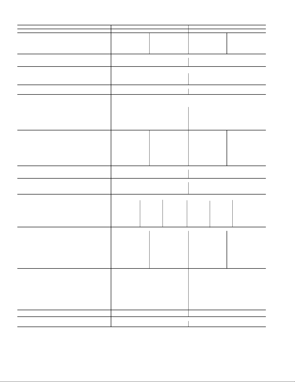
Table 1A — Physical Data 48P2,P3,P4,P5030-050 (cont)
BASE UNIT 48P2,P3,P4,P5040 48P2,P3,P4,P5050
NOMINAL CAPACITY (tons) 40 50
OPERATING WEIGHT (lb) Standard Chassis Extended Chassis Standard Chassis Extended Chassis
Base Unit
Low Heat 5810 6310 6025 6525
High Heat 5940 6440 6155 6655
With Economizer
Low Heat 6110 6610 6325 6825
High Heat 6240 6740 6455 6955
COMPRESSORS Scroll
Quantity...Type 2...ZP103/1...ZP182 2...ZP120/2...ZP137
Oil Charge (oz) per Compressor 110 110
Number of Refrigerant Circuits 22
REFRIGERANT R-410A
Operating Charge (lb), Ckt 1/Ckt 2
Standard Evaporator Coil 21.6/26.7 29.4/29.0
Standard Evaporator with Humidi-MiZer® 21.6/39.1 29.4/41.4
Alternate High-Capacity Evaporator Coil 35.1/37.2 38.2/36.5
Alternate High-Capacity Evaporator with Humidi-MiZer 31.1/49.6 38.2/48.9
CONDENSER COILS Aluminum Novation® Heat Exchanger with Microchannel Coils
Quantity 22
Total Face Area (sq ft) 66.7 66.7
EVAPORATOR COILS
Quantity 1
Total Face Area (sq ft) 45.5
Refrigerant Feed Device...No. per Circuit TXV...2
Standard Evaporator Coils
Rows...Fins/in. 3...15.0 4...15.0
Fin Type Double Wavy Double Wavy
Tube Type Cross Hatched Cross Hatched
Alternate, High-Capacity Evaporator Coils
Rows...Fins/in. 6...16.0 6...16.0
Fin Type Double Wavy Double Wavy
Tube Type Cross Hatched Cross Hatched
HEATING SECTION Low Heat High Heat Low Heat High Heat
Number of Heat Exchangers 714714
Input (MBtuh) 325 650 325 650
Output (MBtuh) (Vertical/Horizontal) 263/260 527/520 263/260 527/520
Temperature Rise Range (F) 10-40 25-55 10-40 25-55
Efficiency (%) (Vertical/Horizontal) 81/80 81/80 81/80 81/80
Burner Orifice Diameter
Quantity (in. ...drill no.) 7 (.1285...30) 14 (.1285...30) 7 (.1285...30) 14 (.1285...30)
Manifold Pressure (in. wg) 3.53.53.53.5
Line Pressure (in. wg) (min...max) 5.0...13.0 5.0...13.0 5.0...13.0 5.0...13.0
Firing Stages 2222
Number of Gas Valves 1212
CONDENSER FANS Propeller Type
Quantity...Diameter (in.) 3...30 4...30
Nominal Cfm 30,000 38,000
Motor Hp...Rpm 1.0...1140 1.0...1140
SUPPLY FAN Centrifugal 25 x 25 in.
Nominal Cfm 14,000 14,000
Maximum Allowable Cfm 20,000 20,000
Maximum Allowable Rpm 900 900
Shaft Diameter at Pulley (in.) 111/
SUPPLY-FAN MOTOR AND DRIVE (Any motor available on any unit)
Motor Hp 7.51015202530*
Motor Frame Size 213T 215T 254T 256T 284T 286T
Efficiency at Full Load (%)
High Efficiency 88.5 89.5 91.0 91.0 91.7 92.4
Premium Efficiency 91.7 91.7 93.0 93.6 93.6 93.6
Fan Pulley Pitch Diameter (in.) 13.7 13.7 13.7 13.7 13.7 12.5
Motor Pulley Pitch Diameter (in.) 3.4 4.3 4.9 5.5 6.5 6.5
Resulting Fan Speed (rpm) 438 549 626 703 830 910
Belts Quantity...Type 2...BX60 2...5VX630 2...5VX630 2...5VX630 2...5VX650 3...5VX630
Center Distance Range (in.) 17.74-14.30 17.74-14.30 17.63...14.01 17.63...14.01 16.63...12.87 16.63...12.87
OPTIONAL POWER EXHAUST† Centrifugal, 18 x 15 in. (Any motor available on any unit)
Quantity...Motor Hp 2...3.0 2...5.0 2...7.5 2...10
Motor Frame Size High Eff 56HZ 184T 213T 215T
Efficiency at Full Load (%) High/Premium 81.0/88.5 87.5/89.5 88.5/91.7 89.5/91.7
Fan Pulley Pitch Diameter (in.) High Eff 11 10.4 12 12
Motor Pulley Pitch Diameter Range (in.) High Eff 4.1-3.1 4.7-3.7 6.0-4.8 7.0-5.8
Motor Pulley Pitch Diameter Factory Setup (in.) 4.14.25.46.4
Blower Shaft Diameter at Pulley (in.) 17/
Fan Rpm Range 500-656 621-785 717-882 854-1000
Factory Setup Fan Rpm 656 703 800 927
Maximum Allowable Rpm 1000 1000 1000 1000
FILTERS
Standard Efficiency Throwaway (Standard)
Quantity...Size (in.) 8...20 x 25 x 2, 8...20 x 20 x 2 8...20 x 25 x 2, 8...20 x 20 x 2
Medium Efficiency (30%) Pleated (Optional)
Quantity...Size (in.) 8...20 x 25 x 2, 8...20 x 20 x 2 8...20 x 25 x 2, 8...20 x 20 x 2
High Efficiency (90%) Bag Filters
with High Velocity Prefilters (Opt)
Quantity...Size (in.)
Bag Filter 6...20 x 24 x 22, 6...20 x 20 x 22 6...20 x 24 x 22, 6...20 x 20 x 22
Prefilter 12...16 x 20 x 2, 3...20 x 24 x 2 12...16 x 20 x 2, 3...20 x 24 x 2
MERV 15 Cartridge Filters with High Velocity Prefilters (Opt)
Quantity...Size (in.)
Cartridge Filter 6...20 x 24 x 12, 6...20 x 20 x 12 6...20 x 24 x 12, 6...20 x 20 x 12
Prefilter 12...16 x 20 x 2, 3...20 x 24 x 2 12...16 x 20 x 2, 3...20 x 24 x 2
OUTSIDE AIR SCREENS
Standard Hood (25%) Quantity...Size (in.) None None
Prem Eff 182T 184T 213T 215T
Prem Eff 11.0 10.4 12 12
Prem Eff 4.1-3.1 4.7-3.7 6.0-4 .8 7.0-5.8
16
OPTIONAL ECONOMIZER FILTER Aluminum Frame, Permanent
Quantity...Size (in.)
LEGEND
MBtuh — Btuh in Thousands
TXV — Thermostatic Expansion Valve
16
17/
16
5...20 x 20 x 2
2...20 x 25 x 1
* 460-3-60 only.
†See Table 7 — Power Exhaust Fan Drive Data on page 9 for more information.
17/
16
111/
16
5...20 x 20 x 1
2...20 x 25 x 1
17/
16
4
Page 5
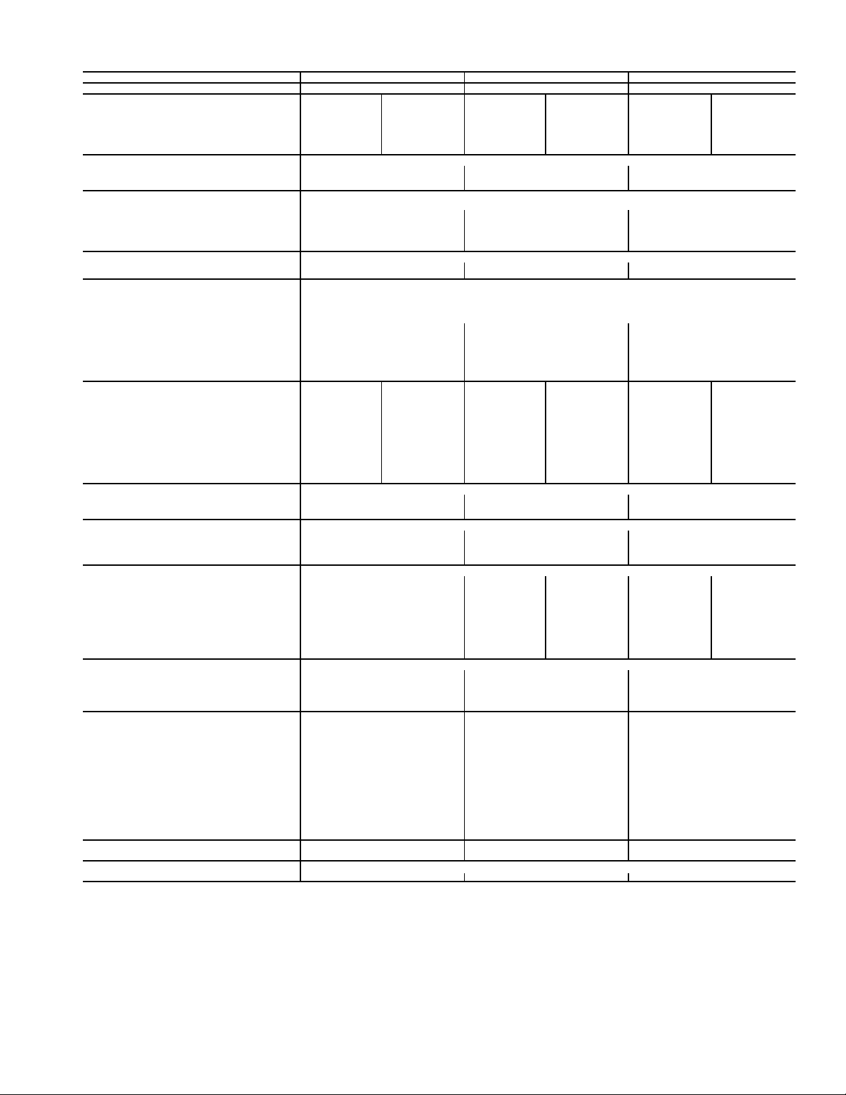
Table 1B — Physical Data 48P2,P3,P4,P5055-070
BASE UNIT 48P2,P3,P4,P5055 48P2,P3,P4,P5060 48P2,P3,P4,P5070
NOMINAL CAPACITY (tons) 55 60 70
OPERATING WEIGHT (lb) Standard Chassis Extended Chassis Standard Chassis Extended Chassis Standard Chassis Extended Chassis
Base Unit
Low Heat 7810 8360 7865 8 415 8205 8755
High Heat 7940 8490 7995 8545 8335 8885
With Economizer
Low Heat 8340 8890 8395 8 945 8735 9285
High Heat 8470 9020 8525 9075 8865 9415
COMPRESSORS Scroll
Quantity...Type 2...ZP137/2...ZP137 2...ZP154/2...ZP154 1...ZP54,1...ZP182/1...ZP54,1...ZP182
Oil Charge (oz) per Compressor 110 110 110
Number of Refrigerant Circuits 22 2
REFRIGERANT R-410A
Operating Charge (lb), Ckt 1/Ckt 2
Standard Evaporator Coil 37.6/37.9 42.2/41.8 43.5/44.8
Standard Evaporator with Humidi-MiZer® 37.6/50.3 42.2/54.2 43.5/57.2
Alternate High-Capacity Evaporator Coil 46.5/45.8 47.6/46.5 55.4/55.5
Alternate High-Capacity Evaporator with
Humidi-MiZer
CONDENSER COILS Aluminum Novation® Heat Exchanger with Microchannel Coils
Quantity 22 4
Total Face Area (sq ft) 66.7 66.7 106.7
EVAPORATOR COILS
Quantity 2
Total Face Area (sq ft) 61.5
Refrigerant Feed Device...No. per Circuit TXV...2
Standard Evaporator Coils
Rows...Fins/in. 4...15 4...15 4...15
Fin Type Double Wavy Double Wavy Double Wavy
Tube Type Cross Hatched Cross Hatched Cross Hatched
Alternate, High-Capacity Evaporator Coils
Rows...Fins/in. 6...16 6...16 6...16
Fin Type Double Wavy Double Wavy Double Wavy
Tube Type Cross Hatched Cross Hatched Cross Hatched
HEATING SECTION Low Heat High Heat Low Heat High Heat Low Heat High Heat
Number of Heat Exchangers 14 21 14 21 14 21
Input (MBtuh) 650 975 650 975 650 975
Output (MBtuh) (Vertical/Horizontal) 527/520 790/780 527/520 790/780 527/520 790/780
Temperature Rise Range (F) 10-40 20-50 10-40 20-50 10-40 20-50
Efficiency (%) (Vertical/Horizontal) 81/80 81/80 81/80 81/80 81/80 81/80
Burner Orifice Diameter
Quantity (in. ...drill no.) 14 (.1285...30) 21 (.1285...30) 14 (.1285...30) 21 (.1285...30) 14 (.1285...30) 21 (.1285...30)
Manifold Pressure (in. wg) 3.5 3.5 3.5 3.5 3.5 3.5
Line Pressure (in. wg) (min...max) 5.0...13.0 5.0...13.0 5.0...13.0 5.0...13.0 5.0...13.0 5.0...13.0
Firing Stages 22222 2
Number of Gas Valves 23232 3
CONDENSER FANS Propeller Type
Quantity...Diameter (in.) 4...30 4...30 4...30
Nominal Cfm 36,000 36,600 39,000
Motor Hp...Rpm 1.0...1140 1.0...1140 1.0...1140
SUPPLY FAN Centrifugal 30 x 27.5 in.
Nominal Cfm 17,500 21,000 24,500
Maximum Allowable Cfm 25,000 30,000 30,000
Maximum Allowable Rpm 800 800 800
Shaft Diameter at Pulley (in.) 111/
SUPPLY-FAN MOTOR AND DRIVE (Any motor available on any unit)
Motor Hp 15 20 25 30 40†
Motor Frame Size 254T 256T 284T 286T S324T
Efficiency at Full Load (%)
High Efficiency 91.0 91.0 91.7 92.4 93.0
Premium Efficiency 93.0 93.6 93.6 93.6 94.5
Fan Pulley Pitch Diameter (in.) 13.7 13.7 13.7 15.5 16.1
Motor Pulley Pitch Diameter (in.) 4.5 5.1 5.5 5.9 6.7
Resulting Fan Speed (rpm) 575 651 703 711 740
Belts Quantity...Type 2...5VX1230 2...5VX1230 2...5VX1230 2...5VX1230 3...5VX1250
Center Distance Range (in.) 48.25-44.00 48.25-44.00 48.50-44.25 48.50-44.25 48.25-44.00
OPTIONAL POWER EXHAUST* Centrifugal, 18 x 15 in. (Any motor available on any unit)
Quantity...Motor Hp 2...5 2...7.5 2...10
Motor Frame Size 184T 213T 215T
Efficiency at Full Load (%) High/Premium 87.5/89.5 88.5/91.7 89.5/91.7
Resulting Fan Rpm 740 820 920
Maximum Allowable Rpm 1000 1000 1000
FILTERS
Standard Efficiency Throwaway (Standard)
Quantity...Size (in.) 12...20 x 25 x 2, 12...20 x 20 x 2 12...20 x 25 x 2, 12...20 x 20 x 2 12...20 x 25 x 2, 12...20 x 20 x 2
Medium Efficiency (30%) Pleated (Optional)
Quantity...Size (in.) 12...20 x 25 x 2, 12...20 x 20 x 2 12...20 x 25 x 2, 12...20 x 20 x 2 12...20 x 25 x 2, 12...20 x 20 x 2
High Efficiency (90%) Bag Filters
with High Velocity Prefilters (Optional)
Quantity...Size (in.)
Bag Filter 6...24 x 24 x 22, 6...24 x 20 x 22 6...24 x 24 x 22, 6...24 x 20 x 22 6...24 x 24 x 22, 6...24 x 20 x 22
Prefilter 6...24 x 24 x 2, 6...20 x 24 x 2 6...24 x 24 x 2, 6...20 x 24 x 2 6...24 x 24 x 2, 6...20 x 24 x 2
MERV 15 Cartridge Filters with
High Velocity Prefilters (Optional)
Quantity...Size (in.)
Cartridge Filter 6...24 x 24 x 12,, 6...24 x 20 x 12 6...24 x 24 x 12,, 6...24 x 20 x 12 6...24 x 24 x 12, 6...24 x 20 x 12
Prefilter 6...24 x 24 x 2, 6...20 x 24 x 2 6...24 x 24 x 2, 6...20 x 24 x 2 6...24 x 24 x 2, 6...20 x 24 x 2
OUTSIDE AIR SCREENS
Standard Hood (25%) Quantity...Size (in.) 4...25 x 16 x 1, 2...20 x 16 x 1 4...25 x 16 x 1, 2...20 x 16 x 1 4...25 x 16 x 1, 2...20 x 16 x 1
OPTIONAL ECONOMIZER FILTER Aluminum Frame, Permanent
Quantity...Size (in.) 12...16 x 25 x 1, 2...16 x 20 x 1 12...16 x 25 x 1, 2...16 x 20 x 1 12...16 x 25 x 1, 2...16 x 20 x 1
LEGEND *See Table 7 — Power Exhaust Fan Drive Data on page 9 for more information.
MBtuh — Btuh in Thousands
TXV — Thermostatic Expansion Valve
46.5/58.2 47.6/58.9 55.4/67.9
16
111/
16
111/
16
5
Page 6
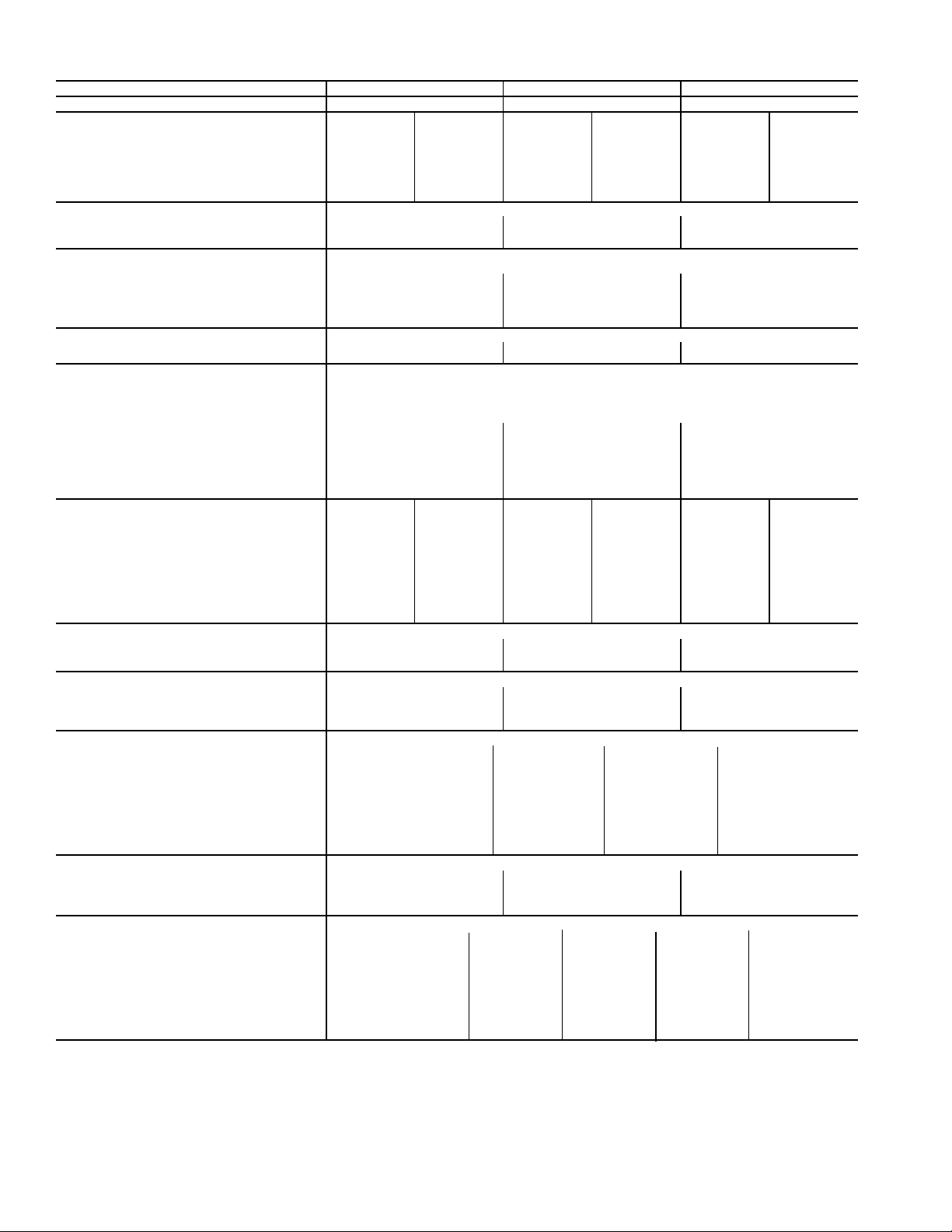
Table 1C — Physical Data 48P2,P3,P4,P5075-100
BASE UNIT 48P2,P3,P4,P5075 48P2,P3,P4,P5090 48P2,P3,P4,P5100
NOMINAL CAPACITY (tons) 75 90 100
OPERATING WEIGHT (lb) Standard
Base Unit
Low Heat 9065 9615 9665 10,215 9685 10,235
High Heat 9195 9745 9795 10,345 9815 10,365
With Economizer
Low Heat 9595 10,145 10,195 10,745 10,215 10,765
High Heat 9725 10,275 10,325 10,875 10,345 10,895
COMPRESSORS Scroll
Quantity...Type 2...ZP82/2...ZP182 3...ZP154,3...ZP154 3...ZP154,3...ZP182
Oil Charge (oz) per Compressor 110 110 110
Number of Refrigerant Circuits 222
REFRIGERANT R-410A
Operating Charge (lb), Ckt 1/Ckt 2
Standard Evaporator Coil 43.8/45.0 50.4/51.3 50.8/52.8
Standard Evaporator with Humidi-MiZer® 43.8/57.4 50.4/69.1 50.8/70.6
Alternate High-Capacity Evaporator Coil 55.1/54.9 61.5/62.9 59.3/62.8
Alternate High-Capacity Evaporator with
Humidi-MiZer
CONDENSER COILS Aluminum Novation® Heat Exchanger with Microchannel Coils
Quantity 466
Total Face Area (sq ft) 106.7 160.0 160.0
EVAPORATOR COILS
Quantity 2
Total Face Area (sq ft) 61.5
Refrigerant Feed Device...No. per Circuit TXV...2
Standard Evaporator Coils
Rows...Fins/in. 4...15 4...15 4...15
Fin Type Double Wavy Double Wavy Double Wavy
Tub e Ty p e Cross Hatched Cross Hatched Cross Hatched
Alternate, High-Capacity Evaporator Coils
Rows...Fins/in. 6...16 6...16 6...16
Fin Type Double Wavy Double Wavy Double Wavy
Tub e Ty p e Cross Hatched Cross Hatched Cross Hatched
HEATING SECTION Low Heat High Heat Low Heat High Heat Low Heat High Heat
Number of Heat Exchangers 232323
Input (MBtuh) 650 975 650 975 650 975
Output (MBtuh) (Vertical/Horizontal) 527/520 790/780 527/520 790/780 527/520 790/780
Temperature Rise Range (F) 10-40 20-50 10-40 20-50 10-40 20-50
Efficiency (%) (Vertical/Horizontal) 81/80 81/80 81/80 81/80 81/80 81/80
Burner Orifice Diameter
Quantity (in. ...drill no.) 7 (.1285...30) 7 (.1285...30) 7 (.1285...30) 7 (.1285...30) 7 (.1285...30) 7 (.1285...30)
Manifold Pressure (in. wg) 3.5 3.5 3.5 3.5 3.5 3.5
Line Pressure (in. wg) (Min...Max) 5.0...13.0 5.0...13.0 5.0...13.0 5.0...13.0 5.0...13.0 5.0...13.0
Number of Gas Valves 232323
CONDENSER FAN Propeller Type
Quantity...Diameter (in.) 4...30 6...30 6...30
Nominal Cfm 39,000 58,000 58,000
Motor Hp (ea)...rpm 1.0...1140 1.0...1140 1.0...1140
STANDARD SUPPLY FAN Forward Curved Centrifugal 36 x 30 in.
Nominal Cfm 24,500 29,750 35,000
Maximum Allowable Cfm 30,000 34,000 40,000
Maximum Allowable Rpm 680 680 680
Shaft Diameter at Pulley (in.) 1
STANDARD SUPPLY-FAN MOTOR AND DRIVE (Any motor available on any unit)
Motor Hp 30 40 50 60
Motor Frame Size S268T S324T S36T S364T
Efficiency at Full Load (%)
High Efficiency 92.4 93.0 93.0 93.6
Premium Efficiency 93.6 94.5 94.5 95.4
Fan Pulley Pitch Diameter (in.) 18.5 18.5 18.5 18.5
Motor Pulley Pitch Diameter (in.) 5.3 5.7 6.5 7.1
Resulting Fan Rpm 501 539 615 672
Belts Quantity...Type 3...5VX1320 4...5VX1320 4...5VX1320 4...5VX1320
Center Distance Range (in.) 47.88-45.01 47.64-44.76 47.42-44.52 47.42-44.52
ALTERNATE, AIRFOIL FAN Airfoil
Nominal Airflow (cfm) 24,500 29,750 35,000
Maximum Allowable Airflow (cfm) 30,000 34,000 40,000
Maximum Allowable Wheel Speed (rpm) 1846 1846 1846
Shaft Diameter at Pulley (in.) 2
ALTERNATE SUPPLY-FAN MOTOR AND DRIVE (Any motor available on any unit)
Motor Hp 30 40 50 60 75
Motor Frame Size S268T S324T S36T S364T 365T
Efficiency at Full Load (%)
High Efficiency 92.4 93.0 93.0 93.6 94.1
Premium Efficiency 93.6 94.5 94.5 95.4 95.4
Fan Pulley Pitch Diameter (in.) 9.7 10.2 8.9 8.9 10.8
Motor Pulley Pitch Diameter (in.) 7.5 8.7 8.1 8.7 11.1
Resulting Fan Rpm 1353 1493 1593 1711 1799
Belts Quantity...Type 2...5VX1150 2...5VX1180 3...5VX1150 3...5VX1150 3...5VX1230
Center Distance Range (in.) 42.96...45.82 42.96...45.57 42.96...45.57 42.45...45.35 42.45...45.35
Chassis
LEGEND *See Table 3 — High-Capacity Power Exhaust Data for more information. See
MBtuh — Btuh in Thousands
TXV — Thermostatic Expansion Valve
Extended
Chassis
Standard
Chassis
Extended
Chassis
Standard
Chassis
55.1/67.3 61.5/80.7 59.3/80.6
11
/
16
11
/
16
111/
211/
16
16
111/
211/
16
16
Table 7 — Power Exhaust Fan Drive Data on page 9 for more information.
Extended
Chassis
6
Page 7
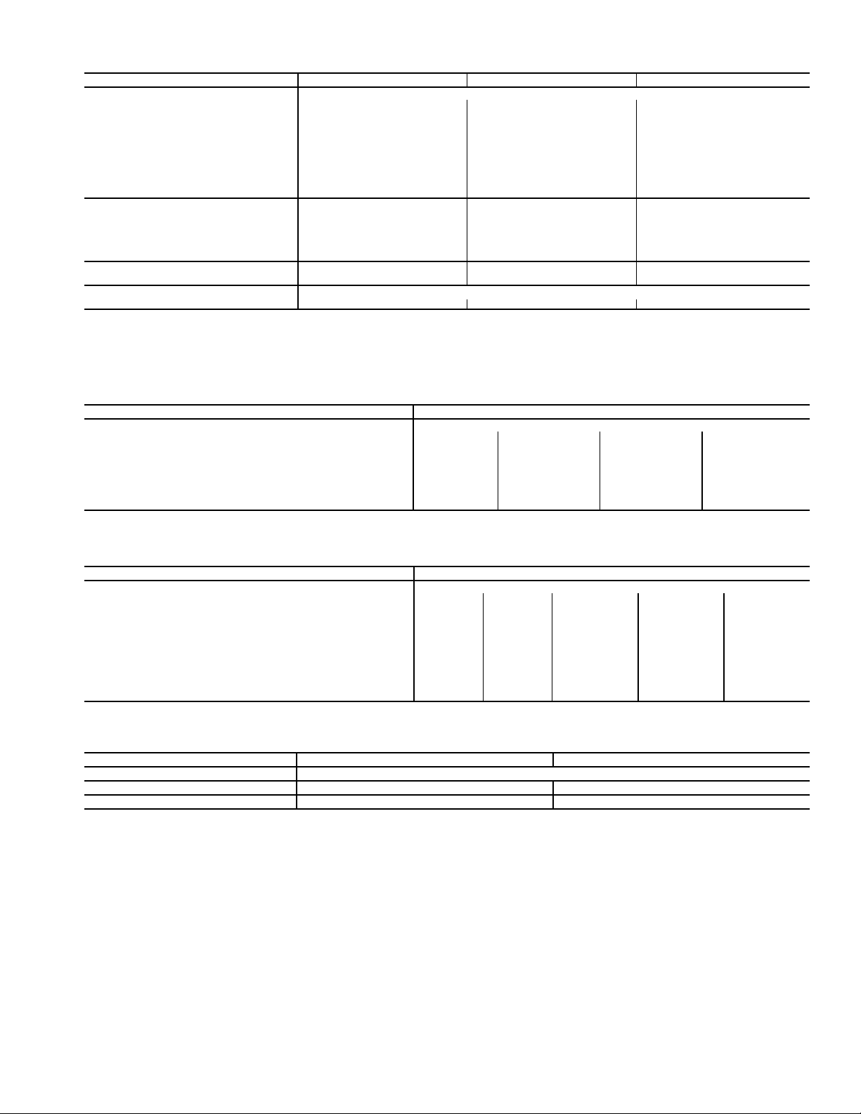
Table 1C — Physical Data 48P2,P3,P4,P5075-100 (cont)
BASE UNIT 48P2,P3,P4,P5075 48P2,P3,P4,P5090 48P2,P3,P4,P5100
OPTIONAL POWER EXHAUST* Centrifugal, 18 x 15 in. (Any motor available on any unit.)
Quantity...Motor Hp 2...5 2...7.5 2...10
Motor Frame Size 184T 213T 215T
Efficiency at Full Load (%)
High Efficiency 87.5 88.5 89.5
Premium Efficiency 89.5 91.7 91.7
Fan Pulley Pitch Diameter (in.) 10.6 10.6 10.6
Motor Pulley Pitch Diameter (in.) 4.5 5.0 5.6
Shaft Diameter at Pulley (in.) 1
Resulting Fan Rpm 740 820 920
Maximum Allowable Rpm 1000 1000 1000
FILTERS
Standard Efficiency Throwaway
(Standard)
Quantity...Size (in.) 12...20 x 25 x 2, 12...20 x 20 x 2 12...20 x 25 x 2, 12...20 x 20 x 2 12...20 x 25 x 2, 12...20 x 20 x 2
30% and 65% Pleated (Optional)
Quantity...Size (in.) 12...20 x 25 x 2, 12...20 x 20 x 2 12...20 x 25 x 2, 12...20 x 20 x 2 12...20 x 25 x 2, 12...20 x 20 x 2
OUTSIDE AIR SCREENS
Standard Hood (25%) Quantity...Size (in.) 4...25 x 16 x 1, 2...20 x 16 x 1 4...25 x 16 x 1, 2...20 x 16 x 1 4...25 x 16 x 1, 2...20 x 16 x 1
OPTIONAL ECONOMIZER FILTER Aluminum Frame, Permanent
Quantity...Size (in.) 12...16 x 25 x 1, 2...16 x 20 x 1 12...16 x 25 x 1, 2...16 x 20 x 1 12...16 x 25 x 1, 2...16 x 20 x 1
LEGEND *See Table 3 — High-Capacity Power Exhaust Data for more information. See
MBtuh — Btuh in Thousands
TXV — Thermostatic Expansion Valve
7
/
16
17/
16
17/
16
Table 7 — Power Exhaust Fan Drive Data on page 9 for more information.
Table 2 — Optional Return Fan Physical Data (48P075-100 Only)
BASE UNIT 48P2,P3,P4,P5075-100
RETURN FAN Plenum Fan, 47.13 in. (Any motor available on any unit.)
Quantity...Motor Hp 1...20 1...25 1...30 1...40
Motor Frame Size 256T 284T 286T 324T
Efficiency at Full Load (%) High/Premium 91.0/93.6 91.7/93.6 92.4/93.6 93.0/93.8
Fan Pulley Pitch Diameter (in.) 8.5 9.8 8.5 8.5
Motor Pulley Pitch Diameter (in.) 5.3 6.7 6.1 6.7
Shaft Diameter at Pulley (in.) 2
Resulting Fan Rpm 1104 1209 1271 1396
Maximum Allowable Rpm 1447 1447 1447 1447
15
/
16
215/
16
215/
16
215/
16
Table 3 — Optional High-Capacity Power Exhaust Physical Data (48P075-100 Only)
BASE UNIT 48P2,P3,P4,P5075-100
POWER EXHAUST Centrifugal, 22 x 20 in., 1
Tot a l Hp 20 30 40 50 60
Quantity...Motor Hp 2...10 2...15 2...20 2...25 2...30
Motor Frame Size S215T D254T S256T S284T S286T
Efficiency at Full Load (%)
High Efficiency 89.5 91 91 91.7 92.4
Premium Efficiency 91.7 93 93.6 93.6 93.6
Fan Sheave Pitch Diameter (in.) 12.4 12.4 11.1 11.1 11.1
Motor Sheave Pitch Diameter (in.) 4.8 5.8 5.9 6.5 6.9
Resulting Fan Rpm 714 841 928 1020 1094
Maximum Allowable Rpm 1175 1175 1175 1175 1175
Belts — Quantity...Type 2...BX93 2...BX93 2...5VX950 2...5VX950 2...5VX950
Table 4 — Optional Humidi-MiZer
UNIT SIZE 48/50P 030-075 090,100
Humidi-MiZer Coil Construction Aluminum Novation
Quantity 11
Face Area (sq ft) 26.7 33.3
11
/16 in. shaft diameter (Any motor available on any unit)
®
Coil Data
®
Coil
7
Page 8
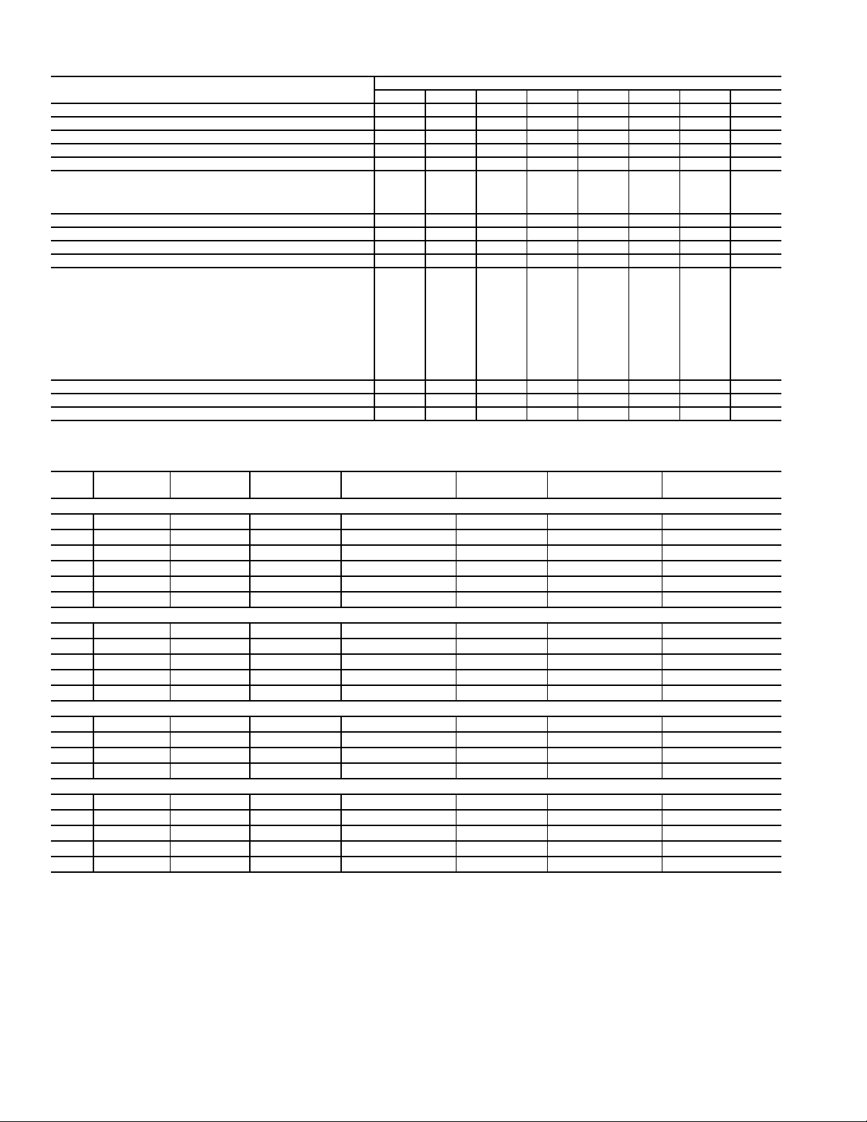
Table 5 — Operating Weights of Options and Accessories (lb)
OPTION OR ACCESSORY
Condenser Section Roof Curb — — 540 540 625 625 625 625
Economizer 300* 300* 530* 530* 530* 530* 530* 530*
Power Exhaust 710* 710* 710* 710* 710* 710* 710* 710*
Barometric Relief 200 200 200 200 200 200 200 200
Double Wall Construction 700 800 900 900 900 900 900 900
Roof Curb
Standard Length 455 495 605 605 605 605 605 605
Extended Length 545 545 1200 1200 — — — —
With High-Capacity Power Exhaust —— ———700700700
High-Efficiency Filters 20 20 20 20 20 20 20 20
Bag Filters and Cartridge Filters 35 35 40 40 40 — — —
Hail Guard 120 150 145 145 210 210 210 210
Inlet Guide Vanes 95 95 115 115 115 115 115 115
Variable Frequency Drive
7.5 hp
10 hp
15 hp
20 hp
25 hp
30 hp
40 hp
50 hp
60 hp
75 hp
High-Capacity Evaporator Coil
Airfoil Fan — — — — — 350 350 350
Humidi-MiZer® Adaptive Dehumidification System 72 72 72 72 72 72 92 92
030,035 040,050 055 060 070 075 090 100
20
20
35
35
53
—
—
—
—
—
150 300 300 300 300 300 300 300
20
20
35
35
53
—
—
—
—
—
—
—
35
35
53
53
53
—
—
—
48/50P UNIT SIZE
—
—
35
35
53
53
53
—
—
—
—
—
35
35
53
53
53
—
—
—
—
—
—
—
—
53
53
53
53
152
—
—
—
—
—
53
53
53
53
152
—
—
—
—
—
53
53
53
53
152
*Includes hood.
Table 6 — Supply Fan Drive Data
HP
SHAFT
DIA (in.)
Sizes 030-050
7.5 1
10 1
15 1
20 1
25 1
30* 1
3
/
8
3
/
8
5
/
8
5
/
8
7
/
8
7
/
8
Sizes 055-070
15 1
20 1
25 1
30 1
40 2
5
/
8
5
/
8
7
/
8
7
/
8
1
/
8
Sizes 075-100 (Forward-Curved Fan)
30 1
40 2
50 2
60 2
7
/
8
1
/
8
1
/
8
3
/
8
Sizes 075-100 (Airfoil Fan)
30 1
40 2
50 2
60 2
75 2
7
/
8
1
/
8
1
/
8
3
/
8
3
/
8
*Sizes 040,050 only. NOTE: Part numbers are Browning Manufacturing Corp. reference.
SPEED
(rpm)
MOTOR
SHEAVE
MOTOR
PITCH DIA (in.)
WHEEL
SHEAVE
WHEEL
PITCH DIA (in.)
QUANTITY
...BELT
438 2BK36 3.4 2B5V136 13.7 2...BX60
549 2B5V42 4.3 2B5V136 13.7 2...5VX630
626 2B5V48 4.9 2B5V136 13.7 2...5VX630
703 2B5V54 5.5 2B5V136 13.7 2...5VX630
830 2B5V64 6.5 2B5V136 13.7 2...5VX650
910 3B5V64 6.5 3B5V124 12.5 3...5VX630
575 2B5V44 4.5 2B5V136 13.7 2...5VX1230
651 2B5V50 5.1 2B5V136 13.7 2...5VX1230
703 2B5V54 5.5 2B5V136 13.7 2...5VX1230
711 2B5V62 6.3 2B5V154 15.5 2...5VX1230
740 3B5V66 6.7 3B5V160 16.1 3...5VX1250
501 3B5V52 5.33 B5V184 18.5 3...5VX1320
539 4B5V56 5.74 B5V184 18.5 4...5VX1320
615 4B5V64 6.54 B5V184 18.5 4...5VX1320
672 4B5V70 7.14 B5V184 18.5 4...5VX1320
1353 2B5V74 7.5 2Q5V97 9.7 2...5VX1150
1493 2B5V86 8.7 2Q5V103 10.2 2...5VX1180
1593 3B5V80 8.1 3R5V90 8.9 3...5VX1150
1711 3B5V86 8.7 3R5V90 8.9 3...5VX1150
1799 3B5V110 11.1 3R5V109 10.8 3...5VX1230
8
Page 9
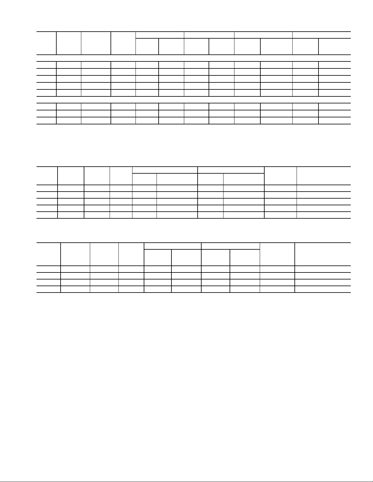
Table 7 — Power Exhaust Fan Drive Data
TOTALHPMOTOR
QTY...HP
MOTOR
SHAFT
DIAMETER
(in.)
FAN
SPEED
RPM
MOTOR SHEAVE BLOWER SHEAVE 48P2,P3 UNITS 48P4,P5 UNITS
Part
Number
Pitch
Diameter
(in.)
Part
Number
Pitch
Diameter
(in.)
BELTS
QTY...P/N
CENTER
DISTANCE
RANGE (in.)
BELTS
QTY...P/N
Sizes 030-050
6* 2...3
6† 2...3 1
10** 2...5 1
15** 2...7.5 1
20** 2...10 1
7
/
8
1
/
1
/
3
/
3
/
656/500 1VL44 4.1-3.1 BK115 11 1...BX71 23.62-26.50 1...BX46 11.40-13.26
656/500 1VP44L 4.1-3.1 BK115 11 1...BX71 23.62-26.50 1...BX46 11.40-13.26
8
785/621 1VP50L 4.7-3.7 BK110 10.4 1...BX71 23.62-26.50 1...BX46 11.16-13.05
8
882/717 1VP65 6.0-4.8 BK130 12 1...BX77 23.62-26.50 1...BX53 11.40-13.26
8
1000/854 1VP75 7.0-5.8 BK130 12 1...BX79 23.62-26.50 1...BX53 11.04-12.95
8
Sizes 055-100
1
10 2...5 1
15 2...7.5 1
20 2...10 1
*High-efficiency motor option.
†Premium-efficiency motor option.
**Applies to both motor options.
/
8
3
/
8
3
/
8
740 2P3V45 4.5 2Q3V106 10.6 2...3VX71 22.71-26.38 2...3VX50 10.91-13.30
820 2P3V50 5.0 2Q3V106 10.6 2...3VX71 22.71-26.38 2...3VX50 10.78-13.20
920 2P3V56 5.6 2Q3V106 10.6 2...3VX75 22.71-26.38 2...3VX50 10.78-13.20
NOTE: Part numbers are Browning Manufacturing Corp. reference.
Table 8 — Optional High-Capacity Power Exhaust Fan Drive Data
TOTALHPMOTOR
QTY...HP
MOTOR
SHAFT
DIA. (in.)
SPEED
RPM
20 2...10 1.375 714 2B5V48 4.8 2B5V124 12.4 2...BX93 32.8 to 36.7
30 2...15 1.625 841 2B5V58 5.8 2B5V124 12.4 2...BX93 32.6 to 36.5
40 2...20 1.625 928 2B5V58 5.9 2B5V110 11.1 2...5VX950 32.6 to 36.5
50 2...25 1.875 1020 2B5V64 6.5 2B5V110 11.1 2...5VX950 32.5 to 36.3
60 2...30 1.875 1094 2B5V68 6.9 2B5V110 11.1 2...5VX950 32.5 to 36.3
MOTOR SHEAVE BLOWER SHEAVE
Part
Number
Pitch Diameter
(in.)
Part
Number
Pitch Diameter
(in.)
QTY...BELT
CENTER DISTANCE
RANGE (in.)
CENTER
DISTANCE
RANGE (in.)
Table 9 — Optional Return Fan Drive Data
TOTALHPMOTOR
QTY...HP
MOTOR
SHAFT
DIA. (in.)
SPEED
RPM
20 1...20 1.625 1104 3B5V52 5.3 3R5V85 8.5 3...5VX1000 38.1 to 41.0
25 1...25 1.875 1209 3B5V66 6.7 3R5V97 9.8 3...5VX1060 38.9 to 41.8
30 1...30 1.875 1271 3B5V60 6.1 3R5V85 8.5 3...5VX1030 38.9 to 41.8
40 1...40 2.125 1396 3B5V66 6.7 3R5V85 8.5 3...5VX1060 39.9 to 42.8
MOTOR SHEAVE BLOWER SHEAVE
Part
Number
Pitch
Diameter
(in.)
Part
Number
Diameter
Pitch
(in.)
QTY...BELT
CENTER DISTANCE
RANGE (in.)
9
Page 10
10
Fig. 1 — Roof Curb — Sizes 030-050
Page 11
11
Fig. 2 — Roof Curb — Sizes 055, 060
Page 12
12
Fig. 3 — Roof Curb — Sizes 070-100
Page 13
13
Fig. 4 — Condenser Section Roof Curb (Sizes 070 and 075)
Page 14
14
Fig. 5 — Condenser Section Roof Curb (Sizes 090 and 100)
Page 15
9 3/4"
"X"-
NO GASKET
4 REF.
DETAIL A-A
A
A
"X"
4
1
3
2
CONDENSER
END SUPPORT
5
5
Fig. 6 — Gasket Location on Roof Curb (Size 070-100 Units)
Fig. 7 — Gasket Location — Condenser Section Roof Curb (Size 070-100 Units)
15
Page 16
Step 8 — Connect Condensate Drain — There
3
1
4
3
2
Fig. 8 — Gasket Location on Roof Curb (48P075-100 Units with Optional High-Capacity Power Exhaust)
are a total of five drain connections required on each unit: one
primary drain (on right-hand side of the unit) and four secondary drains (two on each side of unit).
PRIMARY DRAIN — The primary drain is a 2-in. FPT pipe
connection located on the right-hand side of the unit looking at
the unit from the return air end. See Fig. 12-21. Fig. 22 shows
the additional length of units with an extended chassis.
With field-supplied fittings and pipe sections, plumb the primary condensate drain to the 2-in. FPT connector on the base
rail. Use a trap height of at least 4-in. for size 030-070 units
and 7-in. for size 075-100 units. See Fig. 23 and 24. Install with
a height dimension of at least 2-in. from the top of the exit pipe
from the trap section to the bottom of the connector. Apply a
bead of RTV or similar sealant around the pipe joint at the connector in the base rail.
SECONDARY DRAINS (Units Installed on
Curb) — There are two secondary drain connections on each
side of the unit. See Fig. 25. There are secondary drains on
each side of the unit in the filter section and on each side of the
unit in the supply fan section. There are labels marking each location on the unit base rail. See Fig. 12-21.
Locate the four 1
mounting screws (shipped in a bag taped to the basepan in the
supply fan section, located behind the access panel marked
FAN SECTION). The drain couplings are a 10-gage plate with
1
a 1
/4 in. half coupling welded to the plate.
At each secondary drain hole location, there is a 1
hole pre-drilled in the bottom of the base rail, surrounded by
1
/4-in. drain coupling assemblies and
3
/8-in.
four 0.20-in. engagement holes. Install a drain coupling assembly using screws provided at each secondary drain hole location. See Fig. 26. Do not attach any drain coupling assemblies
in the condenser section base rail.
Using field-supplied fittings and pipe sections, assemble Utraps at each secondary drain fitting. See Fig. 27. Provide a
minimum size of ½-in. pipe for secondary drains. Use a trap at
least 4-in. deep for size 030-070 units and 7-in. deep for size
075-100 units. Apply a bead of RTV or similar sealant around
the drain assemblies.
Consult local plumbing codes for direction on joining multiple drain lines. Total size of any combined line does not need
to exceed nominal 2-in. size of primary drain connection.
Fill the U-traps at the secondary drain locations prior to unit
start-up. Also check the U-traps before each cooling season to
ensure the traps are filled and functioning properly.
SECONDARY DRAINS (Units Installed on Steel Beam or
Slab) — There are two secondary drain connections required
on each side of the unit. There are secondary drains on the bottom of the base rail on each side of the unit in the filter section
and on each side of the unit in the supply fan section. There are
labels marking each location on the unit base rail. See Fig. 12-
21. Drain holes will need to be drilled in these locations at the
side of the base rail. The existing secondary drain holes in the
bottom of the base rail must be sealed. Prior to final positioning
of the unit, apply a bead of RTV or similar sealant around each
secondary drain hole in the bottom of the unit base rail. See
Fig. 27. Install the metal seal plates then position the unit into
final location.
16
Page 17
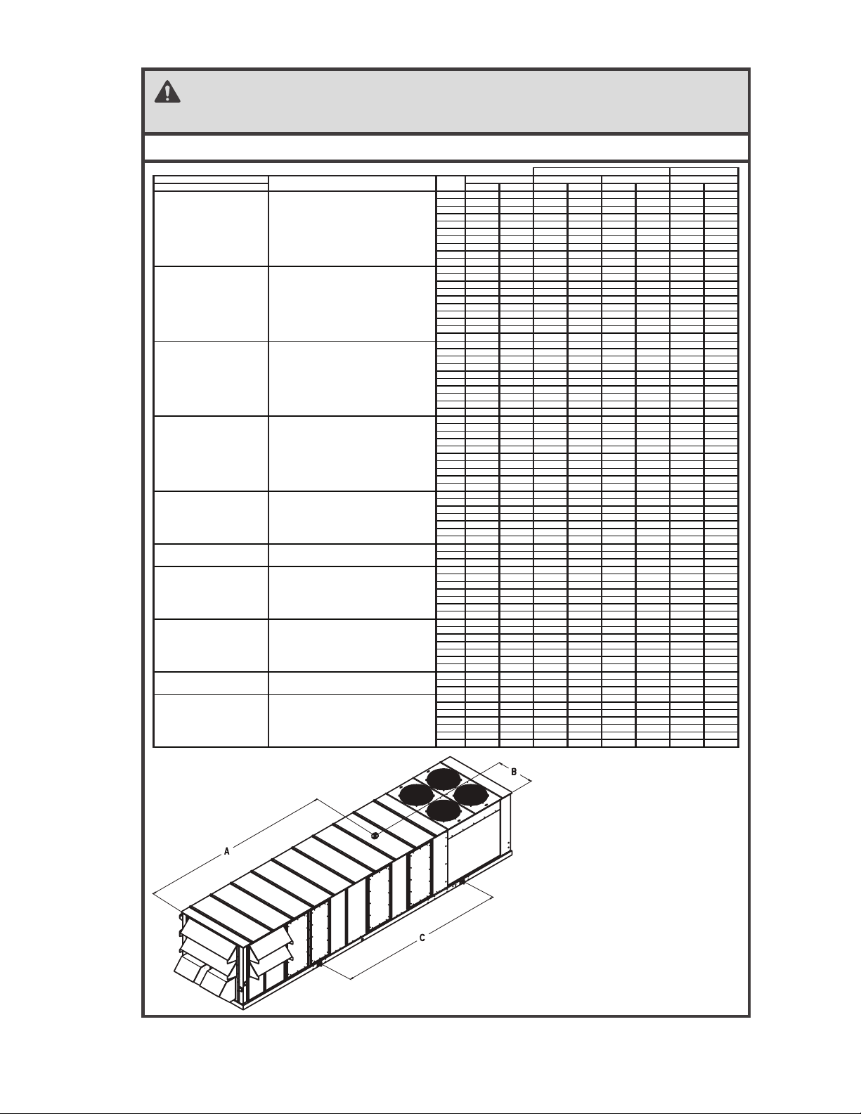
48ZZ501077 2.0
NOTE: Rig with four cables and spread with two 95 inch (2413 MM) spreader bars.
ALL PANELS MUST BE IN PLACE WHEN RIGGING.
CAUTION - NOTICE TO RIGGERS:
1,2,3 4 5 LBS KGS IN MM IN MM IN M M
48P 2,3,4,5 B,D,H
48 P2, P3, P4, P5
030 6019 2730 170.6 4334 45.8 1164 166.4 4227
Vertical Supply/ Return
035 6169 2798 170.9 4342 45.8 1164 166.4 4227
Horizontal Supply/ Return
040 6710 3044 198.2 5035 45.8 1164 185.3 4707
Low Gas Heat
050 6925 3141 201.3 5113 45.8 1164 185.3 4707
055 9220 4182 228.9 5814 45.8 1164 257.5 6541
060 9275 4207 228.5 5803 45.8 1164 257.5 6541
070 9615 4361 244.7 6215 40.2 1021 219.0 5563
075 10665 4838 253.1 6429 40.2 1021 255.7 6495
090 11265 5110 260.9 6628 41.5 1054 255.7 6495
100 11285 5119 260.0 6603 41.5 1054 255.7 6495
48P 2,3,4,5 C,E,J
48 P2, P3, P4, P5
030 6149 2789 169.7 4310 45.8 1164 166.4 4227
Vertical Supply/ Return
035 6299 2857 170.0 4319 45.8 1164 166.4 4227
Horizontal Supply/ Return
040 6840 3103 197.3 5012 45.8 1164 185.3 4707
High Gas Heat
050 7055 3200 200.4 5090 45.8 1164 185.3 4707
055 9350 4241 229.0 5816 45.8 1164 257.5 6541
060 9405 4266 228.5 5805 45.8 1164 257.5 6541
070 9745 4420 244.8 6218 40.2 1021 219.0 5563
075 10795 4897 254.4 6462 40.2 1021 255.7 6495
090 11395 5169 262.1 6657 41.5 1054 255.7 6495
100 11415 5178 261.3 6637 41.5 1054 255.7 6495
48P 2,3,4,5 P,R,W
48 P2, P3, P4, P5
030 6519 2957 187.1 4753 45.8 1164 191.6 4867
Vertical Supply/ Return
035 6669 3025 187.7 4768 45.8 1164 191.6 4867
Horizontal Supply/ Return
040 7210 3270 214.8 5456 45.8 1164 208.2 5288
Low Gas Heat
050 7425 3368 217.9 5534 45.8 1164 208.2 5288
Extended Chassis
055 9770 4432 242.7 6164 45.8 1164 273.2 6939
060 9825 4457 242.2 6151 45.8 1164 273.2 6939
070 9825 4457 258.8 6575 40.2 1021 250.2 6355
075 11215 5087 266.7 6775 40.2 1021 280.8 7132
090 11815 5359 274.7 6976 41.5 1054 280.8 7132
100 11835 5368 273.4 6944 41.5 1054 280.8 7132
48P 2,3,4,5 Q,S,X
48 P2, P3, P4, P5
030 6649 3016 186.1 4726 45.8 1164 191.6 4867
Vertical Supply/ Return
035 6799 3084 186.7 4742 45.8 1164 191.6 4867
Horizontal Supply/ Return
040 7340 3329 213.8 5431 45.8 1164 208.2 5288
High Gas Heat
050 7555 3427 216.8 5507 45.8 1164 208.2 5288
Extended Chassis
055 9900 4491 242.7 6166 45.8 1164 273.2 6939
060 9955 4516 242.3 6153 45.8 1164 273.2 6939
070 10295 4670 258.4 6564 40.2 1021 250.2 6355
075 11345 5146 268.0 6808 40.2 1021 280.8 7132
090 11945 5418 275.8 7005 41.5 1054 280.8 7132
100 11965 5427 274.7 6978 41.5 1054 280.8 7132
50P 2,3 -,A,B,C
50 P2, P3
030 5519 2503 159.2 4043 45.8 1164 148.1 3762
Vertical Supply/ Return
035 5669 2571 159.4 4049 45.8 1164 148.1 3762
040 6210 2817 186.1 4727 45.8 1164 169.5 4305
050 6425 2914 189.3 4807 45.8 1164 169.5 4305
055 8230 3733 212.6 5401 45.8 1164 210.5 5347
060 8285 3758 212.3 5392 45.8 1164 210.5 5347
070 8625 3912 250.5 6362 40.2 1021 176.5 4483
50P 2,3,4,5 -,B,C
50 P2, P3, P4, P5
075 10265 4656 250.1 6354 40.2 1021 255.7 6495
Vertical Supply/ Return
090 10865 4928 258.4 6562 41.5 1054 255.7 6495
Horizontal Supply/ Return
100 10885 4937 257.3 6535 41.5 1054 255.7 6495
50P 2,3 H
50 P2, P3
030 5819 2639 152.3 3867 45.8 1164 166.4 4227
4,5 -
Vert Supply/ Return w/ Ext Plenum
035 5969 2708 152.1 3863 45.8 1164 166.4 4227
040 6510 2953 180.2 4576 45.8 1164 185.3 4707
50 P4, P5
050 6725 3050 183.6 4665 45.8 1164 185.3 4707
Horizontal Supply/ Return
055 8780 3983 231.7 5885 45.8 1164 257.5 6541
060 8835 4008 231.3 5874 45.8 1164 257.5 6541
070 9175 4162 247.5 6287 40.2 1021 219.0 5563
50P 2,3 R,S,T,V,W
50 P2, P3
030 6019 2730 175.4 4456 45.8 1164 173.3 4402
Vertical Supply/ Return
035 6169 2798 176.2 4475 45.8 1164 173.3 4402
w/ Extended Chassis
040 6710 3044 202.8 5151 45.8 1164 194.7 4945
050 6925 3141 205.8 5228 45.8 1164 194.7 4945
055 8780 3983 226.0 5741 45.8 1164 208.2 5288
060 8835 4008 225.6 5731 45.8 1164 208.2 5288
070 9175 4162 264.8 6725 40.2 1021 201.7 5123
50P 2,3,4,5 R,T,V,W
50 P2, P3, P4, P5
075 10815 4906 264.6 6722 40.2 1021 280.8 7132
Vert, Horz Supply/ Return
090 11415 5178 272.9 6932 41.5 1054 280.8 7132
w/ Extended Chassis
100 11435 5187 271.6 6899 41.5 1054 280.8 7132
50P 2,3 P,Y
50 P2, P3
030 6319 2866 166.8 4237 45.8 1164 191.6 4867
4,5 R,W
Vert Supply/ Return w/ Ext Plenum
035 6469 2934 167.1 4244 45.8 1164 191.6 4867
w/ Extended Chassis
040 7010 3180 195.3 4961 45.8 1164 208.2 5288
50 P4, P5
050 7225 3277 198.8 5050 45.8 1164 208.2 5288
Horizontal Supply/ Return
055 9330 4232 245.1 6226 45.8 1164 273.2 6939
w/ Extended Chassis
060 9385 4257 244.7 6214 45.8 1164 273.2 6939
070 9725 4411 260.8 6625 45.8 1164 250.2 6355
B
CENTER OF GRAVITY
LIFTING LUGS
CAWEIGHTMODEL POSITION
UNITS
SIZE
NOTE:
1. Weights do not include economizer or
power exhaust.
Fig. 9 — Rigging Label — Units without Optional Return Fan or High-Capacity Power Exhaust
a48-8455
17
Page 18
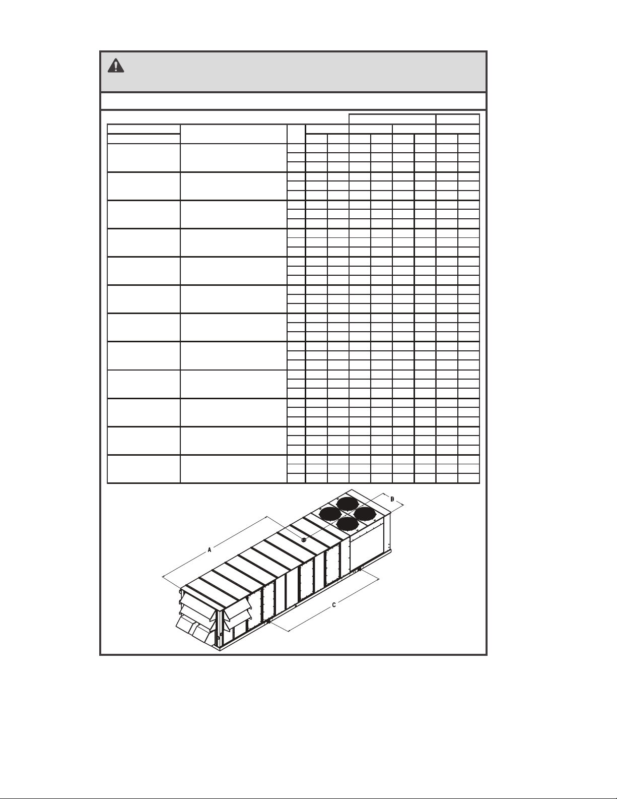
48ZZ501078 2.0
NOTE: Rig with four cables and spread with two 95 inch (2413 MM) spreader bars.
ALL PANELS MUST BE IN PLACE WHEN RIGGING.
CAUTION - NOTICE TO RIGGERS:
MMNIMMNIMMNISGKSBL543,2,1
50P 2,3,4,5 -,B,C 50 P2, P3, P4, P5
075 11921 5407 220.1 5590 40.2 1021 255.7 6495
Vert Supply/Return w/ RE Fan
090 12521 5679 228.4 5800 41.5 1054 255.7 6495
Horz Supply Vert Return w/ RE Fan
100 12541 5689 227.8 5786 41.5 1054 255.7 6495
48P 2,3,4,5 B,D,H 48 P2, P3, P4, P5 Low Gas Heat
075 12321 5589 224.6 5706 40.2 1021 255.7 6495
Vert Supply/Return w/ RE Fan
090 12921 5861 232.6 5908 41.5 1054 255.7 6495
Horz Supply Vert Return w/ RE Fan
100 12941 5870 230.4 5853 41.5 1054 255.7 6495
48P 2,3,4,5 C,E,J 48 P2, P3, P4, P5 High Gas Heat
075 12451 5648 226.9 5764 40.2 1021 255.7 6495
Vert Supply/Return w/ RE Fan
090 13051 5920 233.7 5936 41.5 1054 255.7 6495
Horz Supply Vert Return w/ RE Fan
100 13071 5929 232.9 5915 41.5 1054 255.7 6495
50P 2,3,4,5 R,T,V,W 50 P2, P3, P4, P5
075 12471 5657 231.7 5885 40.2 1021 280.8 7132
Vert Sup/Ret, Horz Sup/ Vert Ret
090 13071 5929 240.1 6098 41.5 1054 280.8 7132
w/ RE Fan, w/ Ext Chassis
100 13091 5938 239.2 6075 41.5 1054 280.8 7132
48P 2,3,4,5 P,R,W 48 P2, P3, P4, P5 Low Gas Heat
075 12871 5838 236.2 6000 40.2 1021 280.8 7132
Vert Sup/Ret, Horz Sup/ Vert Ret
090 13471 6110 244.3 6205 41.5 1054 280.8 7132
w/ RE Fan, w/ Ext Chassis
100 13491 6119 241.8 6142 41.5 1054 280.8 7132
48P 2,3,4,5 Q,S,X 48 P2, P3, P4, P5 High Gas Heat
075 13001 5897 238.5 6058 40.2 1021 280.8 7132
Vert Sup/Ret, Horz Sup/ Vert Ret
090 13601 6169 245.4 6234 41.5 1054 280.8 7132
w/ RE Fan, w/ Ext Chassis
100 13621 6178 244.2 6203 41.5 1054 280.8 7132
48P 2,3,4,5 B,D,H 48 P2, P3, P4, P5 Low Gas Heat
075 13499 6123 290.1 7367 40.2 1021 312.1 7927
Vert Sup/Ret, Horz Sup/Ret
090 14097 6394 297.7 7561 41.5 1054 312.1 7927
w/ Hi Cap PE
100 14119 6404 297.1 7546 41.5 1054 312.1 7927
48P 2,3,4,5 C,E,J 48 P2, P3, P4, P5 High Gas Heat
075 13629 6182 291.3 7400 40.2 1021 312.1 7927
Vert Sup/Ret, Horz Sup/Ret
090 14227 6453 298.9 7593 41.5 1054 312.1 7927
w/ Hi Cap PE
100 14249 6463 298.2 7575 41.5 1054 312.1 7927
50P 2,3,4,5 -,B,C 50 P2, P3, P4, P5
075 13099 5942 287.1 7293 40.2 1021 312.1 7927
Vert Sup/Ret, Horz Sup/Ret
090 13697 6213 295.1 7496 41.5 1054 312.1 7927
w/ Hi Cap PE
100 13719 6223 294.4 7478 41.5 1054 312.1 7927
48P 2,3,4,5 R,T,V,W 48 P2, P3, P4, P5 Low Gas Heat
075 14049 6373 483.5 12280 40.2 1021 337.3 8567
Vert Sup/Ret, Horz Sup/Ret
090 14647 6644 484.3 12302 41.5 1054 337.3 8567
w/ Hi Cap PE w/ Ext Chassis
100 14669 6654 493.8 12542 41.5 1054 337.3 8567
48P 2,3,4,5 P,R,W 48 P2, P3, P4, P5 High Gas Heat
075 14179 6432 483.5 12280 40.2 1021 337.3 8567
Vert Sup/Ret, Horz Sup/Ret
090 14777 6703 484.3 12301 41.5 1054 337.3 8567
w/ Hi Cap PE w/ Ext Chassis
100 14799 6713 493.8 12542 41.5 1054 337.3 8567
50P 2,3,4,5 Q,S,X 50 P2, P3, P4, P5
075 13649 6191 483.5 12281 40.2 1021 337.3 8567
Vert Sup/Ret, Horz Sup/Ret
090 14247 6462 484.4 12304 41.5 1054 337.3 8567
w/ Hi Cap PE w/ Ext Chassis
100 14269 6472 493.8 12543 41.5 1054 337.3 8567
MODEL POSITION
UNITS
SIZE
C
CENTER OF GRAVITY
LIFTING LUGS
WEIGHT A B
Fig. 10 — Rigging Label — Units with Optional Return Fan or High-Capacity Power Exhaust
a48-8456
18
Page 19
3
2
A
B
4
1
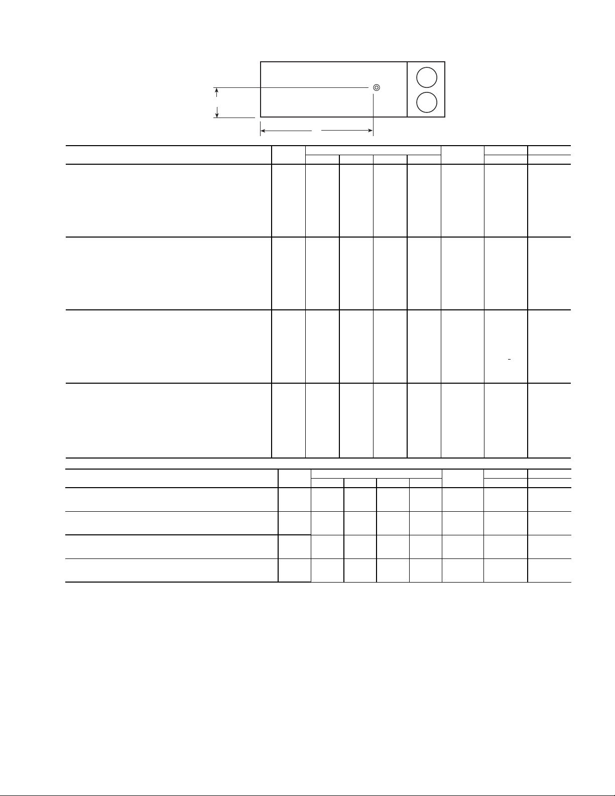
NOTE: The weight distribution and center of gravity information include the impact of an economizer, the largest indoor fan motor, and a VFD (variable frequency
drive). On units with a return fan or high-capacity power exhaust, the largest motors and VFD are also included. These weights do not include the impact of other
factory-installed options such as barometric relief, power exhaust, high-capacity indoor coil, hot water coil, or indoor fan.
48P2,P3,P4,P5 UNITS SIZE
CORNER WEIGHTS (lb)
TOTAL
(lb)
AB
1234 in. in.
Vertical Supply/Return
Horizontal Supply/Return
Low Heat
No Extended Chassis
030 2002 1009 1008 2000 6,019 170
5
/
8
45 7/
8
035 2056 1031 1029 2053 6,169 170 7/
8
45 7/
8
040 1983 1374 1372 1981 6,710 198 1/
4
45 7/
8
050 2079 1386 1384 2076 6,925 201 1/
4
45 7/
8
055 2408 2205 2202 2404 9,220 228 7/
8
45 7/
8
060 2417 2223 2220 2414 9,275 228 1/
2
45 7/
8
070 2950 2450 1913 2303 9,615 244 5/
8
40 1/
4
075 3385 2604 2033 2643 10,665 253 1/
8
40 1/
4
090 3255 2911 2407 2691 11,265 261 41 1/
2
100
3248 2929 2422 2686 11,285 260 41
1
/
2
Vertical Supply/Return
Horizontal Supply/Return
High Heat
No Extended Chassis
030 2034 1042 1041 2032 6,149 169
3
/
4
45 7/
8
035 2088 1064 1062 2085 6,299 170 45 7/
8
040 2013 1410 1408 2010 6,840 197 3/
8
45 7/
8
050 2108 1422 1420 2105 7,055 200 3/
8
45 7/
8
055 2443 2236 2233 2439 9,350 229 45 7/
8
060 2452 2254 2250 2449 9,405 228 1/
2
45 7/
8
070 2991 2481 1937 2335 9,745 244 3/
4
40 1/
4
075 3444 2618 2044 2689 10,795 254 3/
8
40 1/
4
090 3307 2931 2424 2734 11,395 262 1/
8
41 1/
2
100
3303 2946 2436 2731 11,415 261
1
/
4
41 1/
2
Vertical Supply/Return
Horizontal Supply/Return
Low Heat
with Extended Chassis
030 2166 1096 1094 2163 6,519 187
1
/
8
45 7/
8
035 2223 1114 1112 2220 6,669 187 3/
4
45 7/
8
040 2148 1460 1458 2145 7,210 214 3/
4
45 7/
8
050 2244 1471 1469 2241 7,425 217 7/
8
45 7/
8
055 2558 2331 2328 2554 9,770 242 5/
8
45 7/
8
060
2567 2349 2346 2563 9,825 242
1
/
8
45 7/
8
070 3117 2541 2023 2434 10,165 258 7/
8
40 1/
4
075 3551 2747 2145 2773 11,215 266 3/
4
40 1/
4
090 3419 3048 2521 2827 11,815 274 5/
8
41 1/
2
100
3409 3070 2538 2819 11,835 273
3
/
8
41 1/
2
Vertical Supply/Return
Horizontal Supply/Return
High Heat
with Extended Chassis
030 2197 1130 1129 2194 6,649 186
1
/
8
45 7/
8
035 2253 1148 1147 2250 6,799 186 5/
8
45 7/
8
040 2177 1496 1494 2174 7,340 213 3/
4
45 7/
8
050 2272 1508 1506 2269 7,555 216 7/
8
45 7/
8
055 2592 2361 2358 2589 9,900 242 3/
4
45 7/
8
060
2602 2379 2376 2598 9,955 242
1
/
4
45 7/
8
070
3158 2623 2048 2466 10,295 258
1
/
2
40 1/
4
075
3610 2761 2156 2818 11,345 268 40
1
/
4
090
3471 3068 2537 2870 11,945 275
3
/
4
41 1/
2
100
3463 3086 2552 2864 11,965 274
3
/
4
41 1/
2
48P2,P3,P4,P5 UNITS WITH
OPTIONAL HIGH-CAPACITY POWER EXHAUST
SIZE
CORNER WEIGHTS (lb)
TOTAL
(lb)
AB
1234 in. in.
Vertical Supply/Return
Horizontal Supply/Return
Low Heat
075 4171 3410 2662 3256 13,499 290 40
1
/
4
090 4004 3712 3070 3311 14,097 297 5/
8
41 1/
2
100
4002 3726 3081 3309 14,119 297
1
/
8
41 1/
2
Vertical Supply/Return
Horizontal Supply/Return
High Heat
075 4230 3424 2673 3302 13,629 291
3
/
8
40 1/
4
090 4058 3730 3084 3356 14,227 299 41 1/
2
100
4054 3745 3097 3352 14,249 298
1
/
4
41 1/
2
Vertical Supply/Return
Horizontal Supply/Return
Low Heat with Extended Chassis
075 6905 984 768 5391 14,049 483
1
/
2
40 1/
4
090 6484 1534 1268 5362 14,647 484 3/
8
41 1/
2
100
6620 1409 1165 5474 14,669 493
3
/
4
41 1/
2
Vertical Supply/Return
Horizontal Supply/Return
High Heat with Extended Chassis
075 6969 993 776 5441 14,179 483
1
/
2
40 1/
4
090 6541 1547 1280 5409 14,777 484 1/
4
41 1/
2
100
6679 1422 1176 5523 14,799 493
3
/
4
41 1/
2
Fig. 11 — Weight Distribution and Center of Gravity
19
Page 20
1
3
2
A
B
4
1
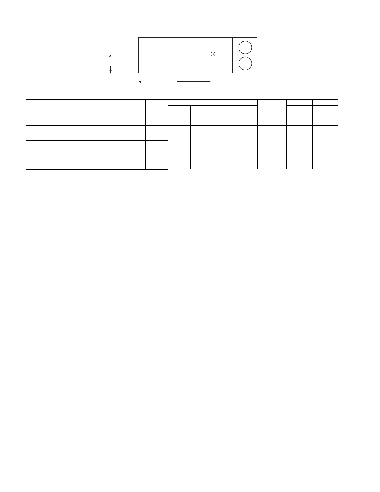
NOTE: The weight distribution and center of gravity information include the impact of an economizer, the largest indoor fan motor, and a VFD (variable frequency
drive). On units with a return fan or high-capacity power exhaust, the largest motors and VFD are also included. These weights do not include the impact of other
factory-installed options such as barometric relief, power exhaust, high-capacity indoor coil, hot water coil, or indoor fan.
48P2,P3,P4,P5 UNITS
WITH OPTIONAL RETURN FAN
SIZE
CORNER WEIGHTS (lb)
TOTAL
(lb)
AB
1234 in. in.
Vertical Supply/Return
Horizontal Supply/Return
Low Heat
075 3470 3449 2693 2709 12,321 224
5
/
8
40 1/
4
090 3327 3745 3097 2751 12,921 232 5/
8
41 1/
2
100
3302 3782 3127 2730 12,941 230
3
/
8
41 1/
2
Vertical Supply/Return
Horizontal Supply/Return
High Heat
075 3543 3449 2693 2766 12,451 226
7
/
8
40 1/
4
090 3377 3767 3115 2793 13,051 233 3/
4
41 1/
2
100
3370 3785 3130 2787 13,071 232
7
/
8
41 1/
2
Vertical Supply/Return
Horizontal Supply/Return
Low Heat with Extended Chassis
075 3609 3618 2825 2818 12,871 236
1
/
4
40 1/
4
090 3467 3906 3230 2867 13,471 244 1/
4
41 1/
2
100
3437 3948 3264 2842 13,491 241
3
/
4
41 1/
2
Vertical Supply/Return
Horizontal Supply/Return
High Heat with Extended Chassis
075 3681 3620 2826 2874 13,001 238
1
/
2
40 1/
4
090 3517 3928 3248 2908 13,601 245 3/
8
41 1/
2
100
3505 3951 3267 2898 13,621 244
1
/
4
41 1/
2
Fig. 11 — Weight Distribution and Center of Gravity (cont)
Locate the four 1
/4-in. drain coupling assemblies and
mounting screws (shipped in a bag taped to the basepan in the
supply fan section, located behind the access panel marked
FAN SECTION). The drain couplings are a 10-gage plate with
1
a 1
/4 in. half coupling welded to the plate.
After final positioning of the unit, perform the following
procedure:
1. At each of the four secondary drain locations (marked
with labels on the unit base rail), position the drain coupling assembly in the side of the base rail. Mark the
screw holes and the drain hole locations on the base rail.
2. Drill holes for drain outlet (use 1
the mounting screws (use
3
3
/8-in. hole saw) and for
/16-in. drill bit).
3. Install a drain coupling assembly using screws provided
at each secondary drain hole location.
4. Using field-supplied fittings and pipe sections, assemble
U-traps at each secondary drain fitting. See Fig. 24. Provide minimum size of ½-in. pipe for secondary drains.
Use a trap at least 4-in. deep for size 030-070 units and
7-in. deep for size 075-100 units.
5. Apply a bead of RTV or similar sealant around the drain
assemblies.
Consult local plumbing codes for direction on joining multiple drain lines. Total size of any combined line does not need to
exceed nominal 2-in. size of primary drain connection.
Fill the U-traps at the secondary drain locations prior to unit
start-up. Also check the U-traps before each cooling season to
ensure the traps are filled and functioning properly.
20
Page 21
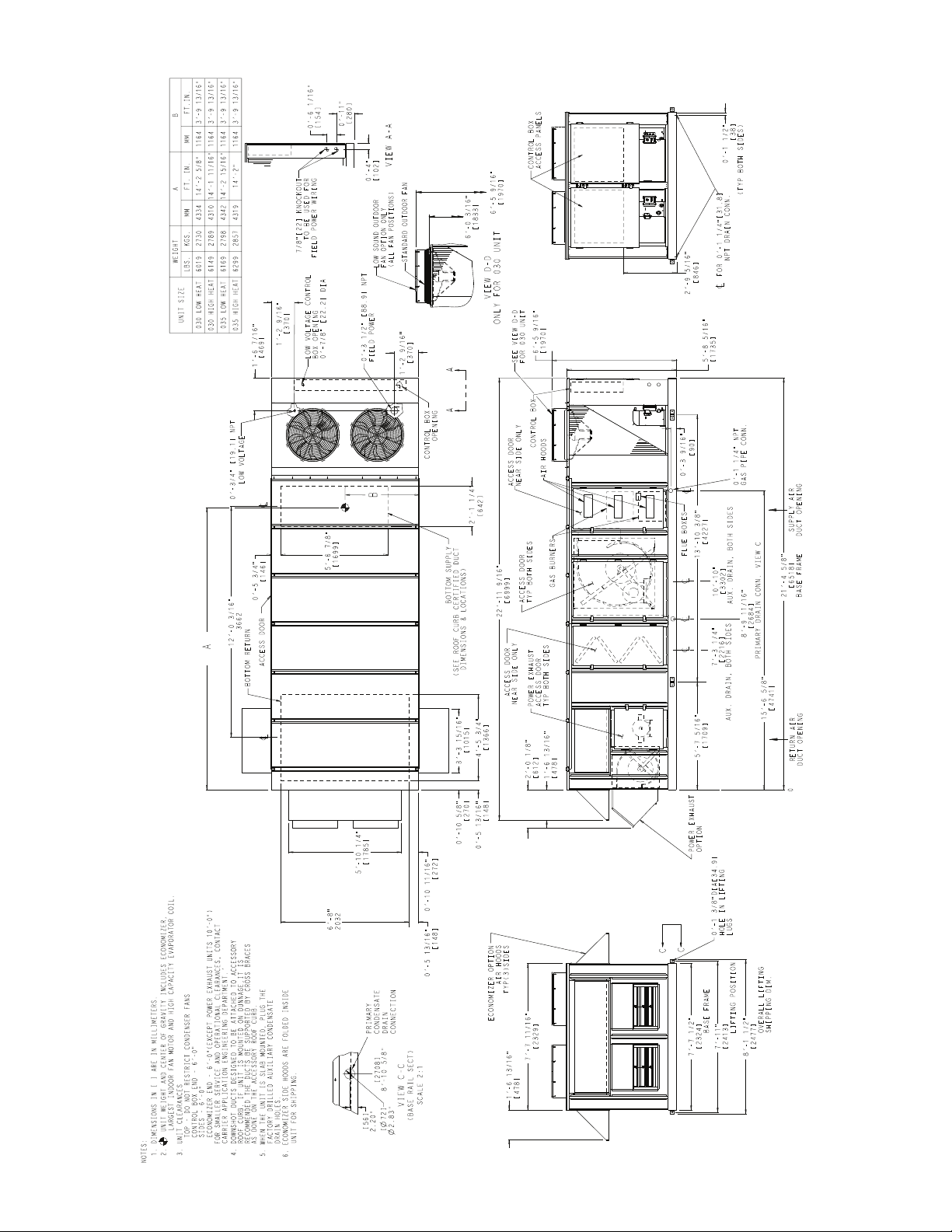
Fig. 12 — Base Unit Dimensional Drawing — 48P2,P3030,035 (Standard Chassis Unit Shown)
a48-8613
21
Page 22
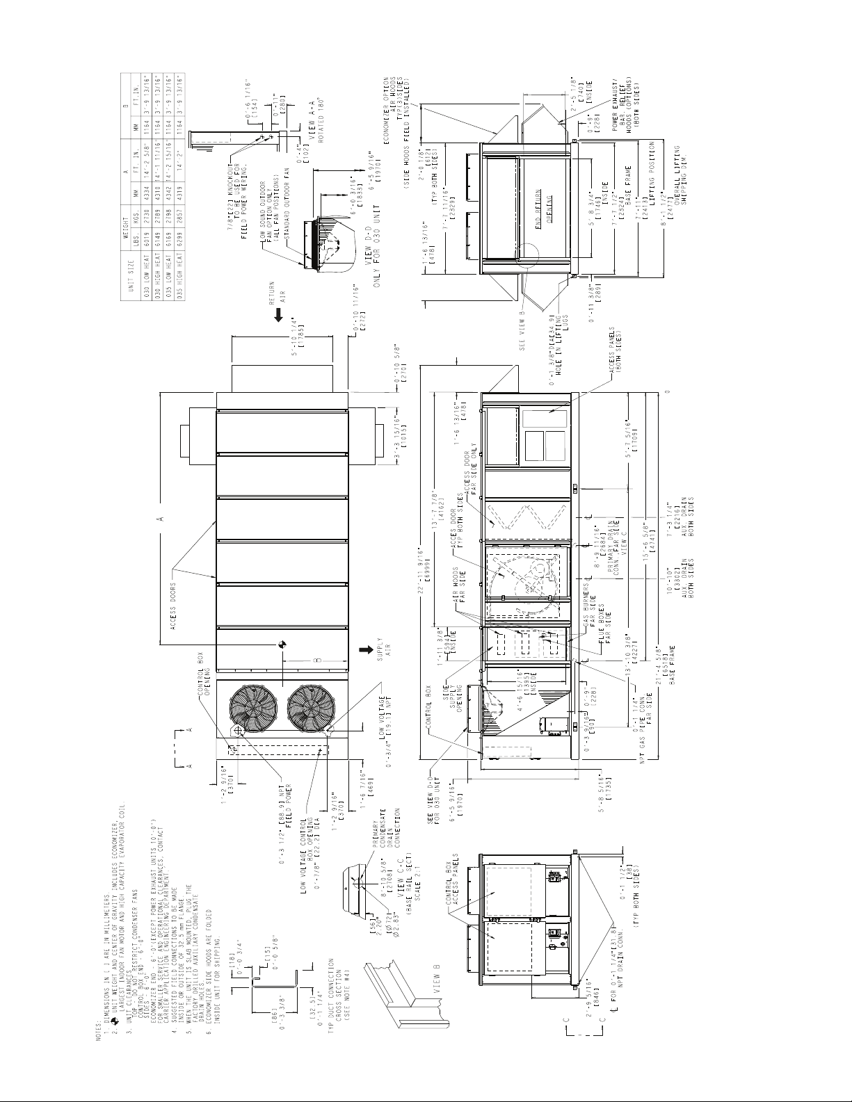
Fig. 13 — Base Unit Dimensional Drawing — 48P4,P5030,035 (Standard Chassis Unit Shown)
a48-8614
22
Page 23
23
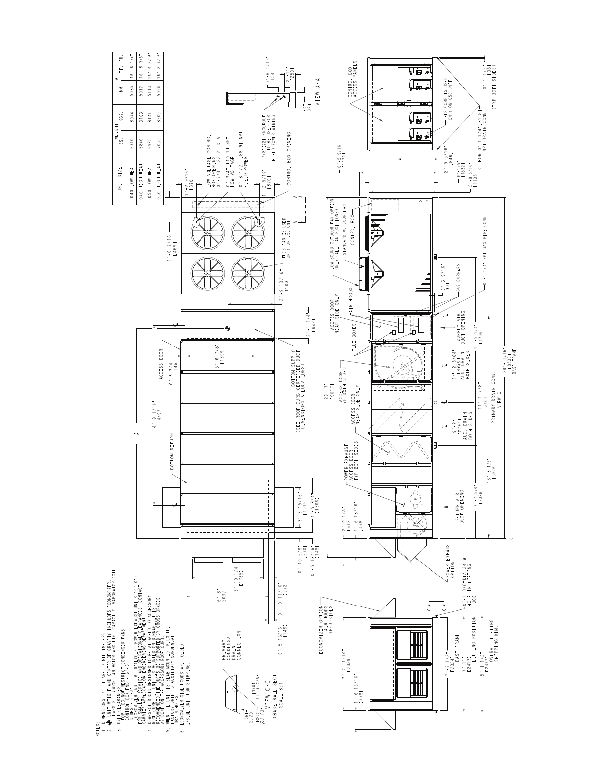
Fig. 14 — Base Unit Dimensional Drawing — 48P2,P3040-050 (Standard Chassis Unit Shown)
a48-8615
Page 24

Fig. 15 — Base Unit Dimensional Drawing — 48P4,P5040-050 (Standard Chassis Unit Shown)
a48-8616
24
Page 25

Fig. 16 — Base Unit Dimensional Drawing — 48P2,P3055,060 (Standard Chassis Unit Shown)
a48-8617
25
Page 26

Fig. 17 — Base Unit Dimensional Drawing — 48P4,P5055,060 (Standard Chassis Unit Shown)
a48-8618
26
Page 27

Fig. 18 — Base Unit Dimensional Drawing — 48P2,P3070 (Standard Chassis Unit Shown)
a48-8619
27
Page 28

Fig. 19 — Base Unit Dimensional Drawing — 48P4,P5070 (Standard Chassis Unit Shown)
a48-8620
28
Page 29

29
Fig. 20 — Base Unit Dimensional Drawing — 48P2,P3075-100 (Standard Chassis Unit with Optional High-Capacity Power Exhaust Shown)
a48-8621
Page 30

Fig. 21 — Base Unit Dimensional Drawing — 48P4,P5075-100 (Standard Chassis Unit with Optional Return Fan Shown)
a48-8622
30
Page 31

A
B
Fig. 22 — Units with Optional Extended Chassis — Location of Coil Tracks
AUXILIARY COIL LOCATION (in.)
UNIT
SIZES
DISTANCE A HEIGHT B
030,035 123.0 6.6
040,050 156.8 6.6
055-070 200.4 6.6
075-100 200.4 6.6
075-100 with High-
Capacity Power Exhaust
279.2 6.6
a48457
A
2” MIN.
(51 mm)
Fig. 23 — Primary Drain Connection
A = 4-in. (102 mm) min — Sizes 030-070
7-in. (178 mm) min — Sizes 075-100
Fig. 24 — Slab-Mounted Condensate
Drain Piping Details
a48-8458
Fig. 25 — Secondary Condensate Drain
Location (Curb Mount)
A = 4-in. (102 mm) min — sizes 030-070
7-in. (178 mm) min — sizes 075-100
Fig. 26 — Curb-Mounted Condensate
Drain Pipe Details
a48-8460
31
2” MIN.
(51 mm)
A
Page 32

Step 9 — Install Outdoor Hoods (Units without
16-GAGE METAL
SEAL PLATE
(FIELD SUPPLIED
FIELD INSTALLED)
BOTTOM OF
BASE RAIL
Fig. 27 — Secondary Drain Seal Plate
Location (Slab Mount)
a48-8459
RTV
(ALL HOODS)
4”
OUTDOOR-AIR HOOD
Fig. 29 — Outdoor-Air and Economizer Hood
OUTDOOR
AIR HOOD
OUTDOOR
AIR HOOD
Fig. 28 — Outdoor Air Hood Installation
(Sizes 030-050)
SIDE HOOD
(ROTATE
OPEN)
SIDE HOOD
(ROTATE
OPEN)
END HOOD
(FIXED)
Fig. 30 — Economizer Outdoor-Air Hood
Installation (Sizes 030-050)
POWER EXHAUST (FIXED)
SIDE HOOD
(ROTATE
OPEN)
SIDE HOOD
(ROTATE
OPEN)
END HOOD
(FIXED)
Fig. 31 — Economizer with Power Exhaust
Outdoor-Air Hood Installation (Sizes 030-050)
a48-8461
Optional High-Capacity Power Exhaust)
UNIT SIZES 030-050
25% Outdoor-Air Hoods (Units without Economizer
Option) (Fig. 28)
1. Outdoor-air hoods are shipped bolted to the unit in a shipping position. Remove the 6 screws holding each 25%
outdoor air hood shipping cover in place.
2. Remove the holddown screw from each upper corner of
each hood.
3. Pivot hoods outward (2 hoods).
4. Install 17 screws around outside of each hood. (Screws
are in the fastener package taped to the basepan inside the
fan section.)
5. Apply a bead of RTV or similar sealant to corner of each
hood at pivot points to prevent water leaks. See Fig. 29.
Economizer Hoods (Units with Economizer Option)
(Fig. 30 and 31)
1. Remove the 4 screws holding each of the 2 economizer
side hoods in place.
2. Pivot hoods outwards (2 hoods).
3. Apply seal strip to vertical flange of hood sides.
4. Install hood sides of hood top using 19 screws (7 each
side, 5 top). Screws are in fastener package located with
the hood sides and seal strip which is taped inside the
unit.
5. Apply a bead of RTV or similar sealant to corners of
economizer hoods at pivot points to prevent water leaks.
See Fig. 29.
UNIT SIZES 055-100
25% Outdoor-Air Hoods (Fig. 32)
are factory installed on the 055-100 units.
— The outdoor-air hoods
Economizer Hoods (Units with Economizer Option) (Fig. 33-35)
1. Remove the 6 screws holding each of the 4 economizer
shipping covers in place.
2. Remove the holddown screw from each upper corner of
each economizer hood.
3. Pivot hoods outward (4 hoods).
4. Apply seal strip to vertical flange of hood sides.
5. Install 18 screws (5 each side, 6 top, and 2 bottom)
around the outside of each hood. (Screws are in the fastener package taped to the basepan inside the fan section.)
6. Apply a bead of RTV or similar sealant to corner of economizer hood at pivot points to prevent water leaks. See
Fig. 29.
32
Page 33

OUTDOOR
AIR HOODS
(FIXED)
Fig. 32 — 25% Outdoor-Air Hood Location
END HOODS
(FIXED)
SIDE HOODS
(ROTATE
OPEN)
SIDE HOODS
(ROTATE OPEN)
Fig. 33 — Economizer Outdoor-Air Hood
Installation (Sizes 055-100)
END HOODS
(FIXED)
SIDE HOODS
(ROTATE
OPEN)
POWER
EXHAUST (FIXED)
SIDE HOODS
(ROTATE OPEN)
Fig. 34 — Economizer with Power Exhaust
Outdoor-Air Hood Installation (Sizes 055-100)
END HOODS
(FIXED)
SIDE HOODS
(ROTATE
OPEN)
RETURN/
EXHAUST (FIXED)
SIDE HOODS
(ROTATE OPEN)
Fig. 35 — Economizer with Return
Fan Outdoor-Air Hood Installation
(Units with Optional Return Fan)
Step 10 — Install Economizer Hoods (Units
with Optional High-Capacity Power
Exhaust) —
intake hoods, 2 on each side of the unit. See Fig. 36. Two small
hoods (one per side) are factory-installed and are pivoted
inside the unit chassis for shipment. Two large hoods are
shipped in packages located inside the unit. The large hoods
(one on each side) require field assembly and mounting.
INSTALL SMALL HOODS — To install the small economizer hoods, perform the following procedure:
1. Remove the 10 screws holding each of the small economizer hood shipping covers in place.
2. Pivot hoods outward. (There are a total of 2 hoods.)
3. Apply seal strip to vertical flange of hood sides.
4. Install 15 screws (4 each side, 7 across top) around the
outside of each hood. Screws are in the fastener package
taped to the basepan inside the fan section.
5. Apply a bead of RTV or similar sealant to corner of economizer hood at pivot points to prevent water leaks. (See
Fig. 29.)
INSTALL LARGE HOODS — Large hoods are shipped disassembled in the economizer section of the unit behind the
large economizer hood shipping cover. See Fig. 37 for assembly details for large economizer hoods. To install the large
economizer hoods, perform the following procedure:
1. Remove the 17 screws holding each of the large economizer hood shipping covers in place.
2. Remove the packages containing the disassembled large
economizer hoods (total of 2 packages). Each package
contains the following (see Fig. 37 for Item numbers): left
hood side (Item 1), right hood side (Item 2), hood top
(Item 3), hood front (Item 4), top filter flange (Item 5), 4
side filter flanges (Item 6), bottom support (Item 7), front
support (Item 8), 6 filters (Item 9), 9 filter clips (Item 10),
seal strip, and fasteners.
3. Place seal strip on backside of bottom support (Item 7)
along entire length of support, covering 6 clearance holes.
4. Attach bottom support piece (Item 7) to unit. Be sure seal
strip is between bottom support and panel on unit.
5. Place seal strip on
hood sides (Items 1 and 2).
6. Attach the side filter flanges (Item 6) to the left and right
hood sides (Items 1 and 2), 2 on each hood side.
7. Attach left and right hood sides (Items 1 and 2) to unit. Be
sure seal strip is between hood side and unit.
8. Place seal strip on
9. Attach top filter flange (Item 5) to hood top (Item 3).
10. Attach top hood to unit and to hood sides. Be sure seal
strip is between hood top and unit.
11. Attach front support (Item 8) between left and right hood
sides.
12. Place seal strip on all filter flanges.
13. Attach filter clips (Item 10) to front and bottom supports
(Items 7 and 8).
14. Install filters (Item 9). Filters are held in place with filter
clips.
15. Attach hood front (Item 4) to hood top and sides.
16. Apply RTV or similar sealant to 6 places shown in
Fig. 37.
The economizer uses a total of 4 outdoor
3
/4-in. flange on both the left and right
3
/4-in. flange on hood top (Item 3).
33
Page 34

ACCESS DOOR
PE VFD
EXHAUST
AIR
LARGE ECONOMIZER
HOOD LOCATION
AUXILIARY
CONTROL BOX
POWER EXHAUST
ACCESS DOOR
SMALL ECONOMIZER
HOOD LOCATION
LEGEND
PE VFD — Power Exhaust Variable Frequency Drive
Fig. 36 — Economizer Hood Location — Units with High-Capacity Power Exhaust
APPLY RTV IN THE
INDICATED AREAS
AND BOTH ENDS OF
BOTTOM FILTER ROW
SEE DETAIL Z
DETAIL Z
SCALE 3:4
ITEM 1
ITEM 2
ITEM 3
ITEM 4
ITEM 5
ITEM 6
ITEM 8
ITEM 9
ITEM 7
ITEM 10
Fig. 37 — Large Economizer Hood Assembly
a48-8462
34
Page 35

Step 11 — Route Field Wiring
UNIT SIZES 030-060 — Field wiring can be brought into the
unit through the basepan and roof curb or through the corner
post in the side of the unit next to the control box.
1
A 3
/2-in. FPT coupling for field power and a 3/4-in. FPT
coupling for 24 v control wiring are provided in the basepan.
There are two
7
/8-in. pilot holes in the corner post as shown on
the certified drawings. Use these holes as pilot holes for making the hole for field-supplied conduit in the corner post for
field power wiring.
CAUTION
Use care when drilling near condenser coil. Damage to unit
could result.
If field power wiring is brought through the roof curb, route
wiring out through one of the holes to the field-supplied disconnect and then back into the unit through the other hole. See
Fig. 38 and 39 for recommended disconnect location.
If power wiring is brought through the side of the unit, route
wiring from field-supplied disconnect through top hole into
unit.
If control wiring is to be brought in through the side of the
7
unit, a
/8-in. diameter hole must be drilled in the corner post
next to the control box.
UNIT SIZES 070-100 — Field wiring is brought into the unit
through the bottom of the control box. Wiring can be brought
through the roof curb through field-supplied watertight connections. See Fig. 40.
5
A 4
/32-in. hole for field power wiring and a 7/8-in. hole for
24 v control wiring are provided in the bottom of the control
box. Field-supplied couplings must be used when routing wiring into the control box.
See Fig. 40 for recommended disconnect location.
Step 12 — Make Field Electrical Connections
IMPORTANT: Units with VFDs (variable frequency
drives) generate, use, and can radiate radio frequency
energy. If units are not installed and used in accordance
with these instructions, they may cause radio interference. They have been tested and found to comply with
limits of a Class A computing device as defined by FCC
(Federal Communications Commission) regulations,
Subpart J of Part 15, which are designed to provide reasonable protection against such interference when operated in a commercial environment.
POWER WIRING — Units are factory wired for the voltage
shown on the unit nameplate. The main terminal block is suitable for use with aluminum or copper wires. Maximum wire
size varies according to disconnect size.
Units without Factory-Installed Disconnect
ing units, provide a disconnect per NEC (National Electrical
Code) of adequate size (MOCP [maximum overcurrent protection] of unit is on the informative plate). All field wiring must
comply with NEC and all local codes. Size wire based on
MCA (minimum circuit amps) on the unit informative plate.
See Fig. 41 for power wiring connections to the unit power
— When install-
terminal block and equipment ground. Maximum wire size is
two (2) 500 MCM (maximum wire size) conductors per pole.
Units with Factory-Installed Disconnect
— The factoryinstalled disconnect is an interlocking, door-type. The disconnect handle locks the door when it is in the ON position. The
disconnect handle must be in the OFF position to open the control box door. The disconnect is located in the control box behind the control box door for all units. See Fig. 42.
All field wiring must comply with NEC and all local codes.
Wire must be sized based on MCA (minimum circuit amps) on
the unit informative plate. See Fig. 43 for power wiring connections to the unit disconnect and equipment ground.
DISCONNECT SIZE
250 Amps
400 Amps
600 Amps
Operating Voltage
— Operating voltage to the compressor
QUANTITY...MAXIMUM WIRE SIZE
(MCM)
1...300
1...600
2...600
must be within the voltage range indicated on the unit nameplate. Voltages between phases must be balanced within 2%,
and the current must be balanced within 10%. See Tables 10-25
for unit electrical data.
Use the following formula to determine the percentage of
voltage imbalance.
Voltage Imbalance
= 100 x
max voltage deviation from average voltage
average voltage
Example: Supply voltage is 460-3-60.
AB = 452 v
BC = 464 v
AC = 455 v
Average Voltage =
455 + 464 + 455
1371
=
3
3
= 457
Determine maximum deviation from average voltage:
(AB) 457 – 452 = 5 v
(BC) 464 – 457 = 7 v
(AC) 457 – 455 = 2 v
Maximum deviation is 7 v.
Determine percent voltage imbalance:
% Voltage Imbalance = 100 x
7
457
= 1.53%
This amount of phase imbalance is satisfactory as it is below the maximum allowable 2%.
IMPORTANT: If the supply voltage phase imbalance is
more than 2%, contact local utility immediately.
Unit failure as a result of operation on improper line voltage
or excessive phase imbalance constitutes abuse and may cause
damage to electrical components.
35
Page 36

RECOMMENDED
FIELD-SUPPLIED
DISCONNECT LOCATION
CONTROL BOX
CONTROL BOX
RECOMMENDED
FIELD-SUPPLIED
DISCONNECT
LOCATION
Fig. 39 — Disconnect Location — Size 040-060 Units
CAUTION
Use care when drilling into corner post to avoid damage to condenser coil.
Fig. 40 — Disconnect Location — Size 070-100 Units
CAUTION
Use care when drilling into corner post to avoid damage to condenser coil.
Fig. 38 — Disconnect Location — Size 030 and 035 Units
CAUTION
Use care when drilling into corner post to avoid damage to condenser coil.
a48-8463
a48-8464
a48-8465
36
Page 37

23
13 12 11
22 21
DISCONNECT
PER NEC
EQUIP
GND
FIELD
WIRE
FACTORY
WIRE
FACTORY-INSTALLED
DISCONNECT
HANDLE LOCATION
FACTORY-INSTALLED
DISCONNECT
(HIDDEN)
21
11
22
12
23
13
DISCONNECT PER NEC
EQUIP GND
TB1
Fig. 43 — Field Power Wiring Connections
for Factory-Installed Disconnect
Fig. 42 — Factory-Installed Disconnect Location (End of Unit Shown)
LEGEND
Fig. 41 — Field Power Wiring Connections
EQUIP — Equipment
GND — Ground
NEC — National Electrical Code
TB — Terminal Block
LEGEND
EQUIP — Equipment
GND — Ground
NEC — National Electrical
Code
a48-8466
a48-8467
37
Page 38

Table 10 — Electrical Data, 48P2,P3,P4,P5030 Units
VOLTAGE
VOLTAGE
3 PH, 60 Hz
RANGE
Min Max Qty
208/230 187 253 1 51.3 300 1 51.3 300 2
460 414 508 1 23.1 150 1 23.1 150 2
COMPRESSOR
No. A1 No. B1
RLA
(ea)
LRA
(ea)
Qty
RLA
(ea)
LRA
(ea)
CONDENSER
FAN MOTOR
EVAPORATOR
FAN MOTOR
Qty FLA Hp FLA Qty
1
7
/
24.2 / 22.0
2
10 30.8 / 28.0
15 46.2 / 42.0
6.6
(ea)
20 59.4 / 54.0
25 74.8 / 68.0
30 88.0 / 80.0
1
7
/
11.0
2
10 14.0
15 21.0
3.3
(ea)
20 27.0
25 34.0
30 40.0
POWER EXHAUST POWER SUPPLY
FLA
Hp
(ea)
—
— — / — 152.8/150.6 200/200
(ea)
MCA
FUSE OR
HACR
BRKR*
2 3 10.6 / 9.6 174.0/169.8 225/200
2 5 16.7 / 15.2 186.2/181.0 225/225
2 7.5 24.2 / 22.0 201.2/194.6 250/225
2 10 30.8 / 28.0 214.4/206.6 250/250
—
— — / — 159.4/156.6 200/200
2 3 10.6 / 9.6 180.6/175.8 225/225
2 5 16.7 / 15.2 192.8/187.0 225/225
2 7.5 24.2 / 22.0 207.8/200.6 250/250
2 10 30.8 / 28.0 221.0/212.6 250/250
—
— — / — 174.8/170.6 225/200
2 3 10.6 / 9.6 196.0/189.8 225/225
2 5 16.7 / 15.2 208.2/201.0 250/250
2 7.5 24.2 / 22.0 223.2/214.6 250/250
2 10 30.8 / 28.0 236.4/226.6 250/250
—
— — / — 190.1/183.3 225/225
2 3 10.6 / 9.6 211.3/202.5 250/250
2 5 16.7 / 15.2 223.5/213.7 250/250
2 7.5 24.2 / 22.0 238.5/227.3 250/250
2 10 30.8 / 28.0 251.7/239.3 300/250
—
— — / — 209.3/200.8 250/250
2 3 10.6 / 9.6 230.5/220.0 300/250
2 5 16.7 / 15.2 242.7/231.2 300/250
2 7.5 24.2 / 22.0 257.7/244.8 300/300
2 10 30.8 / 28.0 270.9/256.8 300/300
—
— — / — 225.8/215.8 300/250
2 3 10.6 / 9.6 247.0/235.0 300/300
2 5 16.7 / 15.2 259.2/246.2 300/300
2 7.5 24.2 / 22.0 274.2/259.8 350/300
2 10 30.8 / 28.0 287.4/271.8 350/350
—— —
23 4.8
25 7.6
27.5 11.0
210 14.0
—— —
23 4.8
25 7.6
27.5 11.0
210 14.0
—— —
23 4.8
25 7.6
27.5 11.0
210 14.0
—— —
23 4.8
25 7.6
27.5 11.0
210 14.0
—— —
23 4.8
25 7.6
27.5 11.0
210 14.0
—— —
23 4.8
25 7.6
27.5 11.0
210 14.0
69.6
79.2
84.8
91.6
97.6
72.6
82.2
87.8
94.6
100.6
79.6
89.2
94.8
101.6
107.6
86.6
96.2
101.8
108.6
114.6
95.3
104.9
110.5
117.3
123.3
102.8
112.4
118.0
124.8
130.8
90
100
100
110
110
90
100
110
110
110
100
110
110
110
125
110
110
125
125
125
125
125
125
150
150
125
150
150
150
150
38
Page 39

Table 10 — Electrical Data, 48P2,P3,P4,P5030 Units (cont)
VO LTAGE
VOLTAGE
3 PH, 60 Hz
575 518 632 1 19.9 109 1 19.9 109 2
RANGE
Min Max Qty
COMPRESSOR
No. A1 No. B1
RLA
(ea)
LRA
(ea)
Qty
RLA
(ea)
LRA
(ea)
CONDENSER
FAN MOTOR
Qty FLA Hp FLA Qty
2.6
(ea)
EVAPORATOR
FAN MOTOR
1
7
/
9.0
2
10 11.0
15 17.0
20 22.0
25 27.0
30 32.0
POWER EXHAUST POWER SUPPLY
Hp
(ea)
—— —
23 3.9
25 6.1
2 7.5 9.0
2 10 11.0
—— —
23 3.9
25 6.1
2 7.5 9.0
2 10 11.0
—— —
23 3.9
25 6.1
2 7.5 9.0
2 10 11.0
—— —
23 3.9
25 6.1
2 7.5 9.0
2 10 11.0
—— —
23 3.9
25 6.1
2 7.5 9.0
2 10 11.0
—— —
23 3.9
25 6.1
2 7.5 9.0
2 10 11.0
FLA
(ea)
MCA
59.0 70
66.8 80
71.2 90
77.0 90
81.0 100
61.0 80
68.8 80
73.2 90
79.0 90
83.0 100
67.0 80
74.8 90
79.2 90
85.0 100
89.0 100
72.5 90
80.3 100
84.7 100
90.5 110
94.5 110
78.8 100
86.6 110
91.0 110
96.8 110
100.8 125
85.0 110
92.8 110
97.2 125
103.0 125
107.0 125
FUSE OR
HACR
BRKR*
LEGEND
FLA — Full Load Amps
HACR — Heating, Air Conditioning, and Refrigeration
Hp — Nominal Horsepower
LRA — Locked Rotor Amps
MCA — Minimum Circuit Amps (for wire sizing)
RLA — Rated Load Amps
* Used to determine minimum disconnect per NEC (National Electrical Code).
NOTE: Units use 1 (low heat) or 2 (high heat) combustion fan motors rated at
0.3 FLA each.
39
Page 40

Table 11 — Electrical Data, 48P2,P3,P4,P5035 Units
VOLTAGE
VOLTAGE
3 PH,
60 Hz
RANGE
Min Max Qty
208/230 187 253 1 55.8 340 1 55.8 340 2
460 414 508 1 26.9 179 1 26.9 179 2
COMPRESSOR
No. A1 No. B1
RLA
(ea)
LRA
(ea)
Qty
RLA
(ea)
LRA
(ea)
CONDENSER
FAN M OTOR
EVAPORATOR FAN
MOTOR
Qty FLA Hp FLA Qty
1
/
7
24.2 / 22.0
2
10 30.8 / 28.0
15 46.2 / 42.0
6.6
(ea)
20 59.4 / 54.0
25 74.8 / 68.0
30 88.0 / 80.0
1
7
/
11.0
2
10 14.0
15 21.0
3.3
(ea)
20 27.0
25 34.0
30 40.0
POWER EXHAUST POWER SUPPLY
Hp
(ea)
—
— — / — 163.0/160.8 200/200
FLA
(ea)
MCA
FUSE OR
HACR
BRKR*
2 3 10.6 / 9.6 184.2/180.0 225/225
2 5 16.7 / 15.2 196.4/191.2 250/225
2 7.5 24.2 / 22.0 211.4/204.8 250/250
2 10 30.8 / 28.0 224.6/216.8 250/250
—
— — / — 169.6/166.8 225/200
2 3 10.6 / 9.6 190.8/186.0 225/225
2 5 16.7 / 15.2 203.0/197.2 250/250
2 7.5 24.2 / 22.0 218.0/210.8 250/250
2 10 30.8 / 28.0 231.2/222.8 250/250
—
— — / — 185.0/180.8 225/225
2 3 10.6 / 9.6 206.2/200.0 250/250
2 5 16.7 / 15.2 218.4/211.2 250/250
2 7.5 24.2 / 22.0 233.4/224.8 250/250
2 10 30.8 / 28.0 246.6/236.8 300/250
—
— — / — 199.1/192.8 250/225
2 3 10.6 / 9.6 220.3/212.0 250/250
2 5 16.7 / 15.2 232.5/223.2 250/250
2 7.5 24.2 / 22.0 247.5/236.8 300/250
2 10 30.8 / 28.0 260.7/248.8 300/300
—
— — / — 218.3/209.8 250/250
2 3 10.6 / 9.6 239.5/229.0 300/250
2 5 16.7 / 15.2 251.7/240.2 300/300
2 7.5 24.2 / 22.0 266.7/253.8 300/300
2 10 30.8 / 28.0 279.9/265.8 350/300
—
— — / — 234.8/224.8 300/300
2 3 10.6 / 9.6 256.0/244.0 300/300
2 5 16.7 / 15.2 268.2/255.2 350/300
2 7.5 24.2 / 22.0 283.2/268.8 350/300
2 10 30.8 / 28.0 296.4/280.8 350/350
— — — 78.1 100
2 3 4.8 87.7 110
2 5 7.6 93.3 110
2 7.5 11.0 100.1 125
2 10 14.0 106.1 125
— — — 81.1 100
2 3 4.8 90.7 110
2 5 7.6 96.3 110
2 7.5 11.0 103.1 125
2 10 14.0 109.1 125
— — — 88.1 110
2 3 4.8 97.7 110
2 5 7.6 103.3 125
2 7.5 11.0 110.1 125
2 10 14.0 116.1 125
— — — 94.2 110
2 3 4.8 103.8 125
2 5 7.6 109.4 125
2 7.5 11.0 116.2 125
2 10 14.0 122.2 125
— — — 102.9 125
2 3 4.8 112.5 125
2 5 7.6 118.1 150
2 7.5 11.0 124.9 150
2 10 14.0 130.9 150
— — — 110.4 150
2 3 4.8 120.0 150
2 5 7.6 125.6 150
2 7.5 11.0 132.4 150
2 10 14.0 138.4 175
40
Page 41

Table 11 — Electrical Data, 48P2,P3,P4,P5035 Units (cont)
VOLTAGE
3 PH,
60 Hz
VOLTAGE
RANGE
Min Max Qty
575 518 632 1 23.7 132 1 23.7 132 2
COMPRESSOR
No. A1 No. B1
RLA
(ea)
LRA
(ea)
Qty
RLA
(ea)
LRA
(ea)
CONDENSER
FAN M OTOR
Qty FLA Hp FLA Qty
EVAPORATOR FAN
1
/
7
2
10 11.0
15 17.0
2.6
(ea)
20 22.0
25 27.0
30 32.0
MOTOR
9.0
POWER EXHAUST POWER SUPPLY
Hp
(ea)
—— —
23 3.9
25 6.1
2 7.5 9.0
2 10 11.0
—— —
23 3.9
25 6.1
2 7.5 9.0
2 10 11.0
—— —
23 3.9
25 6.1
2 7.5 9.0
2 10 11.0
—— —
23 3.9
25 6.1
2 7.5 9.0
2 10 11.0
—— —
23 3.9
25 6.1
2 7.5 9.0
2 10 11.0
—— —
23 3.9
25 6.1
2 7.5 9.0
2 10 11.0
FLA
(ea)
MCA
67.5
75.3
79.7
85.5
89.5
69.5
77.3
81.7
87.5
91.5
75.5
83.3
87.7
93.5
97.5
80.5
88.3
92.7
98.5
102.5
86.4
94.2
98.6
104.4
108.4
92.6
100.4
104.8
110.6
114.6
FUSE OR
HACR BRKR*
90
90
100
100
110
90
100
100
110
110
90
100
110
110
110
100
110
110
110
125
110
110
125
125
125
110
125
125
125
125
LEGEND
FLA — Full Load Amps
HACR — Heating, Air Conditioning, and Refrigeration
Hp — Nominal Horsepower
LRA — Locked Rotor Amps
MCA — Minimum Circuit Amps (for wire sizing)
RLA — Rated Load Amps
* Used to determine minimum disconnect per NEC (National Electrical Code).
NOTE: Units use 1 (low heat) or 2 (high heat) combustion fan motors rated at
0.3 FLA each.
41
Page 42

Table 12 — Electrical Data, 48P2,P3,P4,P5040 Units
VOLTAGE
VOLTAGE
3 PH, 60 Hz
RANGE
Min Max Qty
208/230 187 253 1 55.8 340 2 30.1 225 3
460 414 508 1 26.9 179 2 16.7 114 3
COMPRESSOR
No. A1 No. B1
RLA
(ea)
LRA
(ea)
Qty
RLA
(ea)
LRA
(ea)
CONDENSER
FAN MOTOR
EVAPORATOR
FAN MOTOR
Qty FLA Hp FLA Qty
1
/
7
24.2 / 22.0
2
10 30.8 / 28.0
15 46.2 / 42.0
6.6
(ea)
20 59.4 / 54.0
25 74.8 / 68.0
30 88.0 / 80.0
1
7
/
11.0
2
10 14.0
15 21.0
3.3
(ea)
20 27.0
25 34.0
30 40.0
POWER EXHAUST POWER SUPPLY
FLA
Hp
(ea)
(ea)
MCA
FUSE OR
HACR BRKR*
— — — / — 174.0/171.8 225/225
2 3 10.6 / 9.6 195.2/191.0 250/225
2 5 16.7 / 15.2 207.4/202.2 250/250
2 7.5 24.2 / 22.0 222.4/215.8 250/250
2 10 30.8 / 28.0 235.6/227.8 250/250
— — — / — 180.6/177.8 225/225
2 3 10.6 / 9.6 201.8/197.0 250/250
2 5 16.7 / 15.2 214.0/208.2 250/250
2 7.5 24.2 / 22.0 229.0/221.8 250/250
2 10 30.8 / 28.0 242.2/233.8 250/250
—
— — / — 196.0/191.8 250/225
2 3 10.6 / 9.6 217.2/211.0 250/250
2 5 16.7 / 15.2 229.4/222.2 250/250
2 7.5 24.2 / 22.0 244.4/235.8 300/250
2 10 30.8 / 28.0 257.6/247.8 300/300
—
— — / — 210.1/203.8 250/250
2 3 10.6 / 9.6 231.3/223.0 250/250
2 5 16.7 / 15.2 243.5/234.2 300/250
2 7.5 24.2 / 22.0 258.5/247.8 300/300
2 10 30.8 / 28.0 271.7/259.8 300/300
—
— — / — 229.3/220.8 300/250
2 3 10.6 / 9.6 250.5/240.0 300/300
2 5 16.7 / 15.2 262.7/251.2 300/300
2 7.5 24.2 / 22.0 277.7/264.8 350/300
2 10 30.8 / 28.0 290.9/276.8 350/300
—
— — / — 245.8/235.8 300/300
2 3 10.6 / 9.6 267.0/255.0 350/300
2 5 16.7 / 15.2 279.2/266.2 350/300
2 7.5 24.2 / 22.0 294.2/279.8 350/350
2 10 30.8 / 28.0 307.4/291.8 350/350
— — — 87.9 110
2 3 4.8 97.5 110
2 5 7.6 103.1 125
2 7.5 11.0 109.9 125
2 10 14.0 115.9 125
— — — 90.9 110
2 3 4.8 100.5 125
2 5 7.6 106.1 125
2 7.5 11.0 112.9 125
2 10 14.0 118.9 125
— — — 97.9 110
2 3 4.8 107.5 125
2 5 7.6 113.1 125
2 7.5 11.0 119.9 125
2 10 14.0 125.9 150
— — — 104.0 125
2 3 4.8 113.6 125
2 5 7.6 119.2 125
2 7.5 11.0 126.0 150
2 10 14.0 132.0 150
— — — 112.7 125
2 3 4.8 122.3 150
2 5 7.6 127.9 150
2 7.5 11.0 134.7 150
2 10 14.0 140.7 150
— — — 120.2 150
2 3 4.8 129.8 150
2 5 7.6 135.4 175
2 7.5 11.0 142.2 175
2 10 14.0 148.2 175
42
Page 43

Table 12 — Electrical Data, 48P2,P3,P4,P5040 Units (cont)
VOLTAGE
VOLTAGE
3 PH, 60 Hz
575 518 632 1 23.7 132 2 12.2 80 3
RANGE
Min Max Qty
COMPRESSOR
No. A1 No. B1
RLA
(ea)
LRA
(ea)
Qty
RLA
(ea)
LRA
(ea)
CONDENSER
FAN MOTOR
Qty FLA Hp FLA Qty
2.6
(ea)
EVAPORATOR
FAN MOTOR
1
/
7
9.0
2
10 11.0
15 17.0
20 22.0
25 27.0
30 32.0
POWER EXHAUST POWER SUPPLY
FLA
Hp
(ea)
—— —
23 3.9
25 6.1
2 7.5 9.0
2 10 11.0
—— —
23 3.9
25 6.1
2 7.5 9.0
2 10 11.0
—— —
23 3.9
25 6.1
2 7.5 9.0
2 10 11.0
—— —
23 3.9
25 6.1
2 7.5 9.0
2 10 11.0
—— —
23 3.9
25 6.1
2 7.5 9.0
2 10 11.0
—— —
23 3.9
25 6.1
2 7.5 9.0
2 10 11.0
(ea)
MCA
70.8
78.6
83.0
88.8
92.8
72.8
80.6
85.0
90.8
94.8
78.8
86.6
91.0
96.8
100.8
83.8
91.6
96.0
101.8
105.8
89.7
97.5
101.9
107.7
111.7
95.9
103.7
108.1
113.9
117.9
HACR BRKR*
FUSE OR
90
100
100
110
110
90
100
100
110
110
100
110
110
110
110
100
110
110
125
125
110
110
125
125
125
125
125
125
125
125
LEGEND
FLA — Full Load Amps
HACR — Heating, Air Conditioning, and Refrigeration
Hp — Nominal Horsepower
LRA — Locked Rotor Amps
MCA — Minimum Circuit Amps (for wire sizing)
RLA — Rated Load Amps
* Used to determine minimum disconnect per NEC (National Electrical Code).
NOTE: Units use 1 (low heat) or 2 (high heat) combustion fan motors rated at
0.3 FLA each.
43
Page 44

Table 13 — Electrical Data, 48P2,P3,P4,P5050 Units
VOLTAGE
VOLTAGE
3 PH, 60 Hz
RANGE
Min Max Qty
208/230 187 253 2 33.3 239 2 48.1 245 4
460 414 508 2 17.9 125 2 18.6 125 4
COMPRESSOR
No. A1 No. B1
RLA
(ea)
LRA
(ea)
Qty
RLA
(ea)
LRA
(ea)
CONDENSER
FAN MOTOR
EVAPORATOR
FAN MOTOR
Qty FLA Hp FLA Qty
1
/
7
24.2 / 22.0
2
10 30.8 / 28.0
15 46.2 / 42.0
6.6
(ea)
20 59.4 / 54.0
25 74.8 / 68.0
30 88.0 / 80.0
1
7
/
11.0
2
10 14.0
15 21.0
3.3
(ea)
20 27.0
25 34.0
30 40.0
POWER EXHAUST POWER SUPPLY
FLA
Hp
(ea)
(ea)
MCA
FUSE OR
HACR BRKR*
— — — / — 225.4/223.2 250/250
2 3 10.6 / 9.6 246.6/242.4 250/250
2 5 16.7 / 15.2 258.8/253.6 300/300
2 7.5 24.2 / 22.0 273.8/267.2 300/300
2 10 30.8 / 28.0 287.0/279.2 300/300
— — — / — 232.0/229.2 250/250
2 3 10.6 / 9.6 253.2/248.4 300/250
2 5 16.7 / 15.2 265.4/259.6 300/300
2 7.5 24.2 / 22.0 280.4/273.2 300/300
2 10 30.8 / 28.0 293.6/285.2 300/300
—
— — / — 247.4/243.2 250/250
2 3 10.6 / 9.6 268.6/262.4 300/300
2 5 16.7 / 15.2 280.8/273.6 300/300
2 7.5 24.2 / 22.0 295.8/287.2 300/300
2 10 30.8 / 28.0 309.0/299.2 350/300
—
— — / — 263.5/256.7 300/300
2 3 10.6 / 9.6 284.7/275.9 300/300
2 5 16.7 / 15.2 296.9/287.1 350/300
2 7.5 24.2 / 22.0 311.9/300.7 350/350
2 10 30.8 / 28.0 325.1/312.7 350/350
—
— — / — 282.7/274.2 350/300
2 3 10.6 / 9.6 303.9/293.4 350/350
2 5 16.7 / 15.2 316.1/304.6 350/350
2 7.5 24.2 / 22.0 331.1/318.2 400/350
2 10 30.8 / 28.0 344.3/330.2 400/350
—
— — / — 299.2/289.2 350/350
2 3 10.6 / 9.6 320.4/308.4 400/350
2 5 16.7 / 15.2 332.6/319.6 400/350
2 7.5 24.2 / 22.0 347.6/333.2 400/400
2 10 30.8 / 28.0 360.8/345.2 400/400
— — — 101.9 110
2 3 4.8 111.5 125
2 5 7.6 117.1 125
2 7.5 11.0 123.9 125
2 10 14.0 129.9 150
— — — 104.9 110
2 3 4.8 114.5 125
2 5 7.6 120.1 125
2 7.5 11.0 126.9 150
2 10 14.0 132.9 150
— — — 112.5 125
2 3 4.8 122.1 125
2 5 7.6 127.7 150
2 7.5 11.0 134.5 150
2 10 14.0 140.5 150
— — — 120.0 125
2 3 4.8 129.6 150
2 5 7.6 135.2 150
2 7.5 11.0 142.0 150
2 10 14.0 148.0 150
— — — 128.7 150
2 3 4.8 138.3 150
2 5 7.6 143.9 175
2 7.5 11.0 150.7 175
2 10 14.0 156.7 175
— — — 136.2 175
2 3 4.8 145.8 175
2 5 7.6 151.4 175
2 7.5 11.0 158.2 175
2 10 14.0 164.2 200
44
Page 45

Table 13 — Electrical Data, 48P2,P3,P4,P5050 Units (cont)
VOLTAGE
VOLTAGE
3 PH, 60 Hz
575 518 632 2 12.8 80 2 14.7 100 4
RANGE
Min Max Qty
COMPRESSOR
No. A1 No. B1
RLA
(ea)
LRA
(ea)
Qty
RLA
(ea)
LRA
(ea)
CONDENSER
FAN MOTOR
Qty FLA Hp FLA Qty
2.6
(ea)
EVAPORATOR
FAN MOTOR
1
/
7
9.0
2
10 11.0
15 17.0
20 22.0
25 27.0
30 32.0
POWER EXHAUST POWER SUPPLY
FLA
Hp
(ea)
—— —
23 3.9
25 6.1
2 7.5 9.0
2 10 11.0
—— —
23 3.9
25 6.1
2 7.5 9.0
2 10 11.0
—— —
23 3.9
25 6.1
2 7.5 9.0
2 10 11.0
—— —
23 3.9
25 6.1
2 7.5 9.0
2 10 11.0
—— —
23 3.9
25 6.1
2 7.5 9.0
2 10 11.0
—— —
23 3.9
25 6.1
2 7.5 9.0
2 10 11.0
(ea)
MCA
78.1
85.9
90.3
96.1
100.1
80.1
87.9
92.3
98.1
102.1
86.7
94.5
98.9
104.7
108.7
92.9
100.7
105.1
110.9
114.9
99.2
107.0
111.4
117.2
121.2
105.4
113.2
117.6
123.4
127.4
HACR BRKR*
FUSE OR
90
100
100
110
110
90
100
100
110
110
100
110
110
110
125
110
110
125
125
125
125
125
125
125
125
125
125
125
150
150
LEGEND
FLA — Full Load Amps
HACR — Heating, Air Conditioning, and Refrigeration
Hp — Nominal Horsepower
LRA — Locked Rotor Amps
MCA — Minimum Circuit Amps (for wire sizing)
RLA — Rated Load Amps
* Used to determine minimum disconnect per NEC (National Electrical Code).
NOTE: Units use 1 (low heat) or 2 (high heat) combustion fan motors rated at
0.3 FLA each.
45
Page 46

Table 14 — Electrical Data, 48P2,P3,P4,P5055 Units
VOLTAGE
VOLTAGE
3 PH, 60 Hz
208/230 187 253 2 48.1 245 2 48.1 245 4
460 414 508 2 18.6 125 2 18.6 125 4
575 518 632 2 14.7 100 2 14.7 100 4
LEGEND
FLA — Full Load Amps
HACR — Heating, Air Conditioning, and Refrigeration
Hp — Nominal Horsepower
LRA — Locked Rotor Amps
MCA — Minimum Circuit Amps (for wire sizing)
RLA — Rated Load Amps
* Used to determine minimum disconnect per NEC (National Electrical Code).
NOTE: Units use 2 (low heat) or 3 (high heat) combustion fan motors rated at
0.3 FLA each.
RANGE
Min Max Qty
COMPRESSOR
No. A1 No. B1
RLA
(ea)
LRA
(ea)
Qty
RLA
(ea)
CONDENSER
FAN MOTOR
LRA
Qty FLA Hp FLA Qty
(ea)
6.6
(ea)
3.3
(ea)
2.6
(ea)
EVAPORATOR
FAN MOTOR
15 46.2/42.0
20 59.4/54.0
25 74.8/68.0
30 88.0/80.0
40 114.0/104.0
15 21.0
20 27.0
25 34.0
30 40.0
40 52.0
15 17.0
20 22.0
25 27.0
30 32.0
40 41.0
POWER EXHAUST POWER SUPPLY
FLA
Hp
(ea)
(ea)
— — — / — 277.0/272.8 300/300
2 5.0 16.7 / 15.2 310.4/303.2 350/350
2 7.5 24.2 / 22.0 325.4/316.8 350/350
2 10.0 30.8 / 28.0 338.6/328.8 350/350
— — — / — 293.1/286.3 350/300
2 5.0 16.7 / 15.2 326.5/316.7 350/350
2 7.5 24.2 / 22.0 341.5/330.3 400/350
2 10.0 30.8 / 28.0 354.7/342.3 400/350
—
— — / — 312.3/303.8 350/350
2 5.0 16.7 / 15.2 345.7/334.2 400/400
2 7.5 24.2 / 22.0 360.7/347.8 400/400
2 10.0 30.8 / 28.0 373.9/359.8 400/400
—
— — / — 328.8/318.8 400/350
2 5.0 16.7 / 15.2 362.2/349.2 450/400
2 7.5 24.2 / 22.0 377.2/362.8 450/400
2 10.0 30.8 / 28.0 390.4/374.8 450/450
—
— — / — 361.3/348.8 450/450
2 5.0 16.7 / 15.2 394.7/379.2 500/450
2 7.5 24.2 / 22.0 409.7/392.8 500/450
2 10.0 30.8 / 28.0 422.9/404.8 500/500
—— — 113.9 125
2 5.0 7.6 129.1 150
2 7.5 11.0 135.9 150
2 10.0 14.0 141.9 150
—— — 121.4 125
2 5.0 7.6 136.6 150
2 7.5 11.0 143.4 150
2 10.0 14.0 149.4 175
—— — 130.1 150
2 5.0 7.6 145.3 175
2 7.5 11.0 152.1 175
2 10.0 14.0 158.1 175
—— — 137.6 175
2 5.0 7.6 152.8 175
2 7.5 11.0 159.6 175
2 10.0 14.0 165.6 200
—— — 152.6 200
2 5.0 7.6 167.8 200
2 7.5 11.0 174.6 225
2 10.0 14.0 180.6 225
—— — 90.5 100
2 5.0 6.1 102.7 110
2 7.5 9.0 108.5 125
2 10.0 11.0 112.5 125
—— — 96.7 110
2 5.0 6.1 108.9 125
2 7.5 9.0 114.7 125
2 10.0 11.0 118.7 125
—— — 103.0 125
2 5.0 6.1 115.2 125
2 7.5 9.0 121.0 125
2 10.0 11.0 125.0 150
—— — 109.2 125
2 5.0 6.1 121.4 150
2 7.5 9.0 127.2 150
2 10.0 11.0 131.2 150
—— — 120.5 150
2 5.0 6.1 132.7 150
2 7.5 9.0 138.5 175
2 10.0 11.0 142.5 175
MCA
FUSE OR
HACR BRKR*
46
Page 47

Table 15 — Electrical Data, 48P2,P3,P4,P5060 Units
VOLTAGE
VOLTAGE
3 PH, 60 Hz
208/230 187 253 2 51.3 300 2 51.3 300 4
460 414 508 2 23.1 150 2 23.1 150 4
575 518 632 2 19.9 109 2 19.9 109 4
LEGEND
FLA — Full Load Amps
HACR — Heating, Air Conditioning, and Refrigeration
Hp — Nominal Horsepower
LRA — Locked Rotor Amps
MCA — Minimum Circuit Amps (for wire sizing)
RLA — Rated Load Amps
* Used to determine minimum disconnect per NEC (National Electrical Code).
NOTE: Units use 2 (low heat) or 3 (high heat) combustion fan motors rated at
0.3 FLA each.
RANGE
Min Max Qty
COMPRESSOR
No. A1 No. B1
RLA
(ea)
LRA
(ea)
Qty
RLA
(ea)
CONDENSER
FAN MOTOR
LRA
Qty FLA Hp FLA Qty
(ea)
6.6
(ea)
3.3
(ea)
2.6
(ea)
EVAPORATOR
FAN MOTOR
15 46.2/42.0
20 59.4/54.0
25 74.8/68.0
30 88.0/80.0
40 114.0/104.0
15 21.0
20 27.0
25 34.0
30 40.0
40 52.0
15 17.0
20 22.0
25 27.0
30 32.0
40 41.0
POWER EXHAUST POWER SUPPLY
FLA
Hp
(ea)
(ea)
— — — / — 290.6/286.4 300/300
2 5.0 16.7 / 15.2 324.0/316.8 350/350
2 7.5 24.2 / 22.0 339.0/330.4 350/350
2 10.0 30.8 / 28.0 352.2/342.4 400/350
— — — / — 305.9/299.1 350/350
2 5.0 16.7 / 15.2 339.3/329.5 350/350
2 7.5 24.2 / 22.0 354.3/343.1 400/350
2 10.0 30.8 / 28.0 367.5/355.1 400/400
—
— — / — 325.1/316.6 350/350
2 5.0 16.7 / 15.2 358.5/347.0 400/400
2 7.5 24.2 / 22.0 373.5/360.6 400/400
2 10.0 30.8 / 28.0 386.7/372.6 450/400
—
— — / — 341.6/331.6 400/400
2 5.0 16.7 / 15.2 375.0/362.0 450/400
2 7.5 24.2 / 22.0 390.0/375.6 450/450
2 10.0 30.8 / 28.0 403.2/387.6 450/450
—
— — / — 374.1/361.6 450/450
2 5.0 16.7 / 15.2 407.5/392.0 500/450
2 7.5 24.2 / 22.0 422.5/405.6 500/500
2 10.0 30.8 / 28.0 435.7/417.6 500/500
—— — 132.4 150
2 5.0 7.6 147.6 150
2 7.5 11.0 154.4 175
2 10.0 14.0 160.4 175
—— — 139.4 150
2 5.0 7.6 154.6 175
2 7.5 11.0 161.4 175
2 10.0 14.0 167.4 175
—— — 148.1 175
2 5.0 7.6 163.3 175
2 7.5 11.0 170.1 200
2 10.0 14.0 176.1 200
—— — 155.6 175
2 5.0 7.6 170.8 200
2 7.5 11.0 177.6 200
2 10.0 14.0 183.6 200
—— — 170.6 200
2 5.0 7.6 185.8 225
2 7.5 11.0 192.6 225
2 10.0 14.0 198.6 250
—— — 112.0 125
2 5.0 6.1 124.2 125
2 7.5 9.0 130.0 150
2 10.0 11.0 134.0 150
—— — 117.5 125
2 5.0 6.1 129.7 150
2 7.5 9.0 135.5 150
2 10.0 11.0 139.5 150
—— — 123.8 150
2 5.0 6.1 136.0 150
2 7.5 9.0 141.8 150
2 10.0 11.0 145.8 150
—— — 130.0 150
2 5.0 6.1 142.2 150
2 7.5 9.0 148.0 175
2 10.0 11.0 152.0 175
—— — 141.3 175
2 5.0 6.1 153.5 175
2 7.5 9.0 159.3 200
2 10.0 11.0 163.3 200
MCA
FUSE OR
HACR BRKR*
47
Page 48

Table 16 — Electrical Data, 48P2,P3,P4,P5070 Units
VOLTAGE
VO LTAGE
3 PH, 60 Hz
208/230 187 253 2 51.3 300 2 55.8 340 4
460 414 508 2 23.1 150 2 26.9 179 4
575 518 632 2 19.9 109 2 23.7 132 4
LEGEND
FLA — Full Load Amps
HACR — Heating, Air Conditioning, and Refrigeration
Hp — Nominal Horsepower
LRA — Locked Rotor Amps
MCA — Minimum Circuit Amps (for wire sizing)
RLA — Rated Load Amps
* Used to determine minimum disconnect per NEC (National Electrical Code).
NOTE: Units use 2 (low heat) or 3 (high heat) combustion fan motors rated at
0.3 FLA each.
RANGE
Min Max Qty
COMPRESSOR
No. A1 No. B1
RLA
(ea)
LRA
(ea)
Qty
RLA
(ea)
CONDENSER
FAN MOTOR
LRA
Qty FLA Hp FLA Qty
(ea)
6.6
(ea)
3.3
(ea)
2.6
(ea)
EVAPORATOR
FAN MOTOR
15 46.2/42.0
20 59.4/54.0
25 74.8/68.0
30 88.0/80.0
40 114.0/104.0
15 21.0
20 27.0
25 34.0
30 40.0
40 52.0
15 17.0
20 22.0
25 27.0
30 32.0
40 41.0
POWER EXHAUST POWER SUPPLY
Hp
(ea)
— — — / — 300.8/ 296.6 350/350
2 5.0 16.7 / 15.2 334.2/ 327.0 350/350
2 7.5 24.2 / 22.0 349.2/ 340.6 400/350
2 10.0 30.8 / 28.0 362.4/ 352.6 400/400
— — — / — 314.9/ 308.6 350/350
2 5.0 16.7 / 15.2 348.3/ 339.0 400/350
2 7.5 24.2 / 22.0 363.3/ 352.6 400/400
2 10.0 30.8 / 28.0 376.5/ 364.6 400/400
—
2 5.0 16.7 / 15.2 367.5/ 356.0 400/400
2 7.5 24.2 / 22.0 382.5/ 369.6 450/400
2 10.0 30.8 / 28.0 395.7/ 381.6 450/400
—
2 5.0 16.7 / 15.2 384.0/ 371.0 450/450
2 7.5 24.2 / 22.0 399.0/ 384.6 450/450
2 10.0 30.8 / 28.0 412.2/ 396.6 500/450
—
2 5.0 16.7 / 15.2 416.5/ 401.0 500/500
2 7.5 24.2 / 22.0 431.5/ 414.6 500/500
2 10.0 30.8 / 28.0 444.7/ 426.6 500/500
—— — 140.9 150
2 5.0 7.6 156.1 175
2 7.5 11.0 162.9 175
2 10.0 14.0 168.9 175
—— — 147.0 150
2 5.0 7.6 162.2 175
2 7.5 11.0 169.0 175
2 10.0 14.0 175.0 200
—— — 155.7 175
2 5.0 7.6 170.9 200
2 7.5 11.0 177.7 200
2 10.0 14.0 183.7 200
—— — 163.2 200
2 5.0 7.6 178.4 200
2 7.5 11.0 185.2 225
2 10.0 14.0 191.2 225
—— — 178.2 225
2 5.0 7.6 193.4 225
2 7.5 11.0 200.2 250
2 10.0 14.0 206.2 250
—— — 120.5 125
2 5.0 6.1 132.7 150
2 7.5 9.0 138.5 150
2 10.0 11.0 142.5 150
—— — 125.5 150
2 5.0 6.1 137.7 150
2 7.5 9.0 143.5 150
2 10.0 11.0 147.5 150
—— — 131.4 150
2 5.0 6.1 143.6 150
2 7.5 9.0 149.4 175
2 10.0 11.0 153.4 175
—— — 137.6 150
2 5.0 6.1 149.8 175
2 7.5 9.0 155.6 175
2 10.0 11.0 159.6 175
—— — 148.9 175
2 5.0 6.1 161.1 200
2 7.5 9.0 166.9 200
2 10.0 11.0 170.9 200
FLA
(ea)
— — / — 334.1/ 325.6 400/350
— — / — 350.6/ 340.6 400/400
— — / — 383.1/ 370.6 450/450
MCA
FUSE OR
HACR BRKR*
48
Page 49

Table 17 — Electrical Data — 48P2,P3,P4,P5075 Standard Units
VOLTAGE
VO LTAG E
3 PH, 60 Hz
460 414 508 2 26.9 179 2 26.9 179 4
575 518 632 2 23.7 132 2 23.7 132 4
RANGE
Min Max Qty
COMPRESSOR
No. A1,A2 No. B1,B2
RLA
(ea)
LRA
(ea)
Qty
RLA
(ea)
LRA
(ea)
CONDENSER
FAN MOTOR
Qty FLA Hp FLA Qty
3.3
(ea)
2.6
(ea)
EVAPORATOR
FAN MOTOR
30 40.0
40 52.0
50 65.0
60 77.0
75 96.0
30 32.0
40 41.0
50 52.0
60 62.0
75 77.0
POWER
EXHAUST
Hp
FLA
(ea)
— — — 170.8 200
2 5.0 7.6 186.0 225
2 7.5 11.0 192.8 225
2 10.0 14.0 198.8 225
— — — 185.8 225
2 5.0 7.6 201.0 250
2 7.5 11.0 207.8 250
2 10.0 14.0 213.8 250
— — — 202.1 250
2 5.0 7.6 217.3 250
2 7.5 11.0 224.1 250
2 10.0 14.0 230.1 250
— — — 217.1 250
2 5.0 7.6 232.3 300
2 7.5 11.0 239.1 300
2 10.0 14.0 245.1 300
— — — 240.8 300
2 5.0 7.6 256.0 350
2 7.5 11.0 262.8 350
2 10.0 14.0 268.8 350
— — — 145.2 175
2 5.0 6.1 157.4 175
2 7.5 9.0 163.2 175
2 10.0 11.0 167.2 175
— — — 156.5 175
2 5.0 6.1 168.7 200
2 7.5 9.0 174.5 200
2 10.0 11.0 178.5 200
— — — 170.2 200
2 5.0 6.1 182.4 225
2 7.5 9.0 188.2 225
2 10.0 11.0 192.2 225
— — — 182.7 225
2 5.0 6.1 194.9 250
2 7.5 9.0 200.7 250
2 10.0 11.0 204.7 250
— — — 201.5 250
2 5.0 6.1 213.7 250
2 7.5 9.0 219.5 250
2 10.0 11.0 223.5 300
(ea)
POWER SUPPLY
MCA
HACR BRKR*
FUSE OR
LEGEND
FLA — Full Load Amps
HACR — Heating, Air Conditioning, and Refrigeration
Hp — Nominal Horsepower
LRA — Locked Rotor Amps
MCA — Minimum Circuit Amps (for wire sizing)
RLA — Rated Load Amps
* Used to determine minimum disconnect per NEC (National Electrical Code).
NOTE: Units use 2 (low heat) or 3 (high heat) combustion fan motors rated at
0.3 FLA each.
49
Page 50

Table 18 — Electrical Data — 48P2,P3,P4,P5075 Units with Optional High-Capacity Power Exhaust
VOLTAGE
VO LTAG E
3 PH, 60 Hz
460 414 508 2 26.9 179 2 26.9 179 4
575 518 632 2 23.7 132 2 23.7 132 4
RANGE
Min Max Qty
COMPRESSOR
No. A1,A2 No. B1,B2
RLA
(ea)
LRA
(ea)
Qty
RLA
(ea)
CONDENSER
FAN MOTOR
LRA
Qty FLA Hp FLA Qty
(ea)
3.3
(ea)
2.6
(ea)
EVAPORATOR
FAN MOTOR
30 40.0
40 52.0
50 65.0
60 77.0
75 96.0
30 32.0
40 41.0
50 52.0
60 62.0
75 77.0
POWER
EXHAUST
Hp
FLA
(ea)
2 10 14.0 198.8 225
2 15 21.0 212.8 250
2 20 27.0 224.8 250
2 25 34.0 238.8 250
2 30 40.0 250.8 300
2 10 14.0 213.8 250
2 15 21.0 227.8 250
2 20 27.0 239.8 250
2 25 34.0 253.8 300
2 30 40.0 265.8 300
2 10 14.0 230.1 250
2 15 21.0 244.1 300
2 20 27.0 256.1 300
2 25 34.0 270.1 300
2 30 40.0 282.1 300
2 10 14.0 245.1 300
2 15 21.0 259.1 300
2 20 27.0 271.1 300
2 25 34.0 285.1 350
2 30 40.0 297.1 350
2 10 14.0 268.8 350
2 15 21.0 282.8 350
2 20 27.0 294.8 350
2 25 34.0 308.8 400
2 30 40.0 320.8 400
2 10 11.0 167.2 175
2 15 17.0 179.2 200
2 20 22.0 189.2 200
2 25 27.0 199.2 225
2 30 32.0 209.2 225
2 10 11.0 178.5 200
2 15 17.0 190.5 225
2 20 22.0 200.5 225
2 25 27.0 210.5 250
2 30 32.0 220.5 250
2 10 11.0 192.2 225
2 15 17.0 204.2 250
2 20 22.0 214.2 250
2 25 27.0 224.2 250
2 30 32.0 234.2 250
2 10 11.0 204.7 250
2 15 17.0 216.7 250
2 20 22.0 226.7 250
2 25 27.0 236.7 250
2 30 32.0 246.7 300
2 10 11.0 223.5 300
2 15 17.0 235.5 300
2 20 22.0 245.5 300
2 25 27.0 255.5 300
2 30 32.0 265.5 300
(ea)
MCA
POWER SUPPLY
FUSE OR
HACR BRKR*
LEGEND
FLA — Full Load Amps
HACR — Heating, Air Conditioning, and Refrigeration
Hp — Nominal Horsepower
LRA — Locked Rotor Amps
MCA — Minimum Circuit Amps (for wire sizing)
RLA — Rated Load Amps
* Used to determine minimum disconnect per NEC (National Electrical Code).
NOTE: Units use 2 (low heat) or 3 (high heat) combustion fan motors rated at
0.3 FLA each.
50
Page 51

Table 19 — Electrical Data — 48P2,P3,P4,P5075 Units with Optional Return Fan
VOLTAGE
VOLTAGE
3 PH, 60 Hz
460 414 508 2 26.9 179 2 26.9 179 4
575 518 632 2 23.7 132 2 23.7 132 4
RANGE
Min Max Qty
COMPRESSOR
No. A1 No. B1
RLA
(ea)
LRA
(ea)
Qty
RLA
(ea)
LRA
(ea)
CONDENSER
FAN MOTOR
Qty FLA Hp FLA Qty
3.3
(ea)
2.6
(ea)
EVAPORATOR
FAN MOTOR
30 40.0
40 52.0
50 65.0
60 77.0
75 96.0
30 32.0
40 41.0
50 52.0
60 62.0
75 77.0
POWER EXHAUST POWER SUPPLY
FLA
Hp
(ea)
1 20 27.0 197.8 225
1 25 34.0 204.8 225
1 30 40.0 210.8 250
1 40 52.0 225.8 250
1 20 27.0 212.8 250
1 25 34.0 219.8 250
1 30 40.0 225.8 250
1 40 52.0 237.8 250
1 20 27.0 229.1 250
1 25 34.0 236.1 300
1 30 40.0 242.1 300
1 40 52.0 254.1 300
1 20 27.0 244.1 300
1 25 34.0 251.1 300
1 30 40.0 257.1 300
1 40 52.0 269.1 300
1 20 27.0 267.8 350
1 25 34.0 274.8 350
1 30 40.0 280.8 350
1 40 52.0 292.8 350
1 20 22.0 167.2 175
1 25 27.0 172.2 200
1 30 32.0 177.2 200
1 40 41.0 188.5 225
1 20 22.0 178.5 200
1 25 27.0 183.5 200
1 30 32.0 188.5 225
1 40 41.0 197.5 225
1 20 22.0 192.2 225
1 25 27.0 197.2 225
1 30 32.0 202.2 250
1 40 41.0 211.2 250
1 20 22.0 204.7 250
1 25 27.0 209.7 250
1 30 32.0 214.7 250
1 40 41.0 223.7 250
1 20 22.0 223.5 300
1 25 27.0 228.5 300
1 30 32.0 233.5 300
1 40 41.0 242.5 300
(ea)
MCA
FUSE OR HACR
BRKR*
LEGEND
FLA — Full Load Amps
HACR — Heating, Air Conditioning, and Refrigeration
Hp — Nominal Horsepower
LRA — Locked Rotor Amps
MCA — Minimum Circuit Amps (for wire sizing)
RLA — Rated Load Amps
* Used to determine minimum disconnect per NEC (National Electrical Code).
NOTE: Units use 2 (low heat) or 3 (high heat) combustion fan motors rated at
0.3 FLA each.
51
Page 52

Table 20 — Electrical Data — 48P2,P3,P4,P5090 Standard Units
VOLTAGE
VOLTAGE
3 PH, 60 Hz
460 414 508 3 23.1 150 3 23.1 150 6
575 518 632 3 19.9 109 3 19.9 109 6
RANGE
Min Max Qty
COMPRESSOR
No. A1 No. B1
RLA
(ea)
LRA
(ea)
Qty
RLA
(ea)
LRA
CONDENSER
FAN MOTOR
Qty FLA Hp FLA Qty
(ea)
3.3
(ea)
2.6
(ea)
EVAPORATOR
FAN MOTOR
30 40.0
40 52.0
50 65.0
60 77.0
75 96.0
30 32.0
40 41.0
50 52.0
60 62.0
75 77.0
POWER EXHAUST POWER SUPPLY
FLA
Hp
(ea)
— — — 208.4 225
2 5 7.6 223.6 250
2 7.5 11.0 230.4 250
2 10.0 14.0 236.4 250
— — — 223.4 250
2 5 7.6 238.6 250
2 7.5 11.0 245.4 250
2 10 14.0 251.4 300
— — — 239.7 300
2 5 7.6 254.9 300
2 7.5 11.0 261.7 300
2 10 14.0 267.7 300
— — — 254.7 300
2 5 7.6 269.9 300
2 7.5 11.0 276.7 350
2 10 14.0 282.7 350
— — — 278.4 350
2 5 7.6 293.6 350
2 7.5 11.0 300.4 350
2 10 14.0 306.4 400
— — — 175.0 200
2 5 6.1 187.2 200
2 7.5 9.0 193.0 200
2 10.0 11.0 197.0 225
— — — 186.3 225
2 5 6.1 198.5 225
2 7.5 9.0 204.3 225
2 10 11.0 208.3 225
— — — 200.0 250
2 5 6.1 212.2 250
2 7.5 9.0 218.0 250
2 10 11.0 222.0 250
— — — 212.5 250
2 5 6.1 224.7 250
2 7.5 9.0 230.5 250
2 10 11.0 234.5 250
— — — 231.3 300
2 5 6.1 243.5 300
2 7.5 9.0 249.3 300
2 10 11.0 253.3 300
(ea)
MCA
FUSE OR HACR
BRKR*
LEGEND
FLA — Full Load Amps
HACR — Heating, Air Conditioning, and Refrigeration
Hp — Nominal Horsepower
LRA — Locked Rotor Amps
MCA — Minimum Circuit Amps (for wire sizing)
RLA — Rated Load Amps
* Used to determine minimum disconnect per NEC (National Electrical Code).
NOTE: Units use 2 (low heat) or 3 (high heat) combustion fan motors rated at
0.3 FLA each.
52
Page 53

Table 21 — Electrical Data — 48P2,P3,P4,P5090 Units with Optional High-Capacity Power Exhaust
VOLTAGE
VOLTAGE
3 PH, 60 Hz
460 414 508 3 23.1 150 3 23.1 150 6
575 518 632 3 19.9 109 3 19.9 109 6
RANGE
Min Max Qty
COMPRESSOR
No. A1 No. B1
RLA
(ea)
LRA
(ea)
Qty
RLA
(ea)
CONDENSER
FAN MOTOR
LRA
Qty FLA Hp FLA Qty
(ea)
3.3
(ea)
2.6
(ea)
EVAPORATOR
FAN MOTOR
30 40.0
40 52.0
50 65.0
60 77.0
75 96.0
30 32.0
40 41.0
50 52.0
60 62.0
75 77.0
POWER EXHAUST POWER SUPPLY
FLA
Hp
(ea)
2 10 14.0 236.4 250
2 15 21.0 250.4 300
2 20 27.0 262.4 300
2 25 34.0 276.4 300
2 30 40.0 288.4 300
2 10 14.0 251.4 300
2 15 21.0 265.4 300
2 20 27.0 277.4 300
2 25 34.0 291.4 300
2 30 40.0 303.4 350
2 10 14.0 267.7 300
2 15 21.0 281.7 300
2 20 27.0 293.7 350
2 25 34.0 307.7 350
2 30 40.0 319.7 350
2 10 14.0 282.7 350
2 15 21.0 296.7 350
2 20 27.0 308.7 350
2 25 34.0 322.7 350
2 30 40.0 334.7 400
2 10 14.0 306.4 400
2 15 21.0 320.4 400
2 20 27.0 332.4 400
2 25 34.0 346.4 400
2 30 40.0 358.4 450
2 10 11.0 197.0 225
2 15 17.0 209.0 225
2 20 22.0 219.0 250
2 25 27.0 229.0 250
2 30 32.0 239.0 250
2 10 11.0 208.3 225
2 15 17.0 220.3 250
2 20 22.0 230.3 250
2 25 27.0 240.3 250
2 30 32.0 250.3 300
2 10 11.0 222.0 250
2 15 17.0 234.0 250
2 20 22.0 244.0 250
2 25 27.0 254.0 300
2 30 32.0 264.0 300
2 10 11.0 234.5 250
2 15 17.0 246.5 300
2 20 22.0 256.5 300
2 25 27.0 266.5 300
2 30 32.0 276.5 300
2 10 11.0 253.3 300
2 15 17.0 265.3 300
2 20 22.0 275.3 350
2 25 27.0 285.3 350
2 30 32.0 295.3 350
(ea)
MCA
FUSE OR HACR
BRKR*
LEGEND
FLA — Full Load Amps
HACR — Heating, Air Conditioning, and Refrigeration
Hp — Nominal Horsepower
LRA — Locked Rotor Amps
MCA — Minimum Circuit Amps (for wire sizing)
RLA — Rated Load Amps
* Used to determine minimum disconnect per NEC (National Electrical Code).
NOTE: Units use 2 (low heat) or 3 (high heat) combustion fan motors rated at
0.3 FLA each.
53
Page 54

Table 22 — Electrical Data — 48P2,P3,P4,P5090 Units with Optional Return Fan
VOLTAGE
VOLTAGE
3 PH, 60 Hz
460 414 508 3 23.1 150 3 23.1 150 6
575 518 632 3 19.9 109 3 19.9 109 6
RANGE
Min Max Qty
COMPRESSOR
No. A1 No. B1
RLA
(ea)
LRA
(ea)
Qty
RLA
(ea)
LRA
CONDENSER
FAN MOTOR
Qty FLA Hp FLA Qty
(ea)
3.3
(ea)
2.6
(ea)
EVAPORATOR
FAN MOTOR
30 40.0
40 52.0
50 65.0
60 77.0
75 96.0
30 32.0
40 41.0
50 52.0
60 62.0
75 77.0
POWER EXHAUST POWER SUPPLY
FLA
Hp
(ea)
1 20 27.0 235.4 250
1 25 34.0 242.4 250
1 30 40.0 248.4 250
1 40 52.0 263.4 300
1 20 27.0 250.4 300
1 25 34.0 257.4 300
1 30 40.0 263.4 300
1 40 52.0 275.4 300
1 20 27.0 266.7 300
1 25 34.0 273.7 300
1 30 40.0 279.7 300
1 40 52.0 291.7 350
1 20 27.0 281.7 350
1 25 34.0 288.7 350
1 30 40.0 294.7 350
1 40 52.0 306.7 350
1 20 27.0 305.4 400
1 25 34.0 312.4 400
1 30 40.0 318.4 400
1 40 52.0 330.4 400
1 20 22.0 197.0 225
1 25 27.0 202.0 225
1 30 32.0 207.0 225
1 40 41.0 218.3 250
1 20 22.0 208.3 225
1 25 27.0 213.3 250
1 30 32.0 218.3 250
1 40 41.0 227.3 250
1 20 22.0 222.0 250
1 25 27.0 227.0 250
1 30 32.0 232.0 250
1 40 41.0 241.0 250
1 20 22.0 234.5 250
1 25 27.0 239.5 300
1 30 32.0 244.5 300
1 40 41.0 253.5 300
1 20 22.0 253.3 300
1 25 27.0 258.3 300
1 30 32.0 263.3 300
1 40 41.0 272.3 300
(ea)
MCA
FUSE OR HACR
BRKR*
LEGEND
FLA — Full Load Amps
HACR — Heating, Air Conditioning, and Refrigeration
Hp — Nominal Horsepower
LRA — Locked Rotor Amps
MCA — Minimum Circuit Amps (for wire sizing)
RLA — Rated Load Amps
* Used to determine minimum disconnect per NEC (National Electrical Code).
NOTE: Units use 2 (low heat) or 3 (high heat) combustion fan motors rated at
0.3 FLA each.
54
Page 55

Table 23 — Electrical Data — 48P2,P3,P4,P5100 Standard Units
VOLTAGE
VOLTAGE
3 PH, 60 Hz
460 414 508 3 23.1 150 3 26.9 179 6
575 518 632 3 19.9 109 3 23.7 132 6
RANGE
Min Max Qty
COMPRESSOR
No. A1 No. B1
RLA
(ea)
LRA
(ea)
Qty
RLA
(ea)
LRA
(ea)
CONDENSER
FAN MOTOR
Qty FLA Hp FLA Qty
3.3
(ea)
2.6
(ea)
EVAPORATOR
FAN MOTOR
30 40.0
40 52.0
50 65.0
60 77.0
75 96.0
30 32.0
40 41.0
50 52.0
60 62.0
75 77.0
POWER EXHAUST POWER SUPPLY
FLA
Hp
(ea)
— — — 219.8 250
2 5.0 7.6 235.0 250
2 7.5 11.0 241.8 250
2 10.0 14.0 247.8 250
— — — 234.8 250
2 5.0 7.6 250.0 300
2 7.5 11.0 256.8 300
2 10.0 14.0 262.8 300
— — — 251.1 300
2 5.0 7.6 266.3 300
2 7.5 11.0 273.1 300
2 10.0 14.0 279.1 300
— — — 266.1 300
2 5.0 7.6 281.3 350
2 7.5 11.0 288.1 350
2 10.0 14.0 294.1 350
— — — 289.8 350
2 5.0 7.6 305.0 400
2 7.5 11.0 311.8 400
2 10.0 14.0 317.8 400
— — — 186.4 200
2 5.0 6.1 198.6 225
2 7.5 9.0 204.4 225
2 10.0 11.0 208.4 225
— — — 197.7 225
2 5.0 6.1 209.9 250
2 7.5 9.0 215.7 250
2 10.0 11.0 219.7 250
— — — 211.4 250
2 5.0 6.1 223.6 250
2 7.5 9.0 229.4 250
2 10.0 11.0 233.4 250
— — — 223.9 250
2 5.0 6.1 236.1 250
2 7.5 9.0 241.9 300
2 10.0 11.0 245.9 300
— — — 242.7 300
2 5.0 6.1 254.9 300
2 7.5 9.0 260.7 300
2 10.0 11.0 264.7 300
(ea)
MCA
FUSE OR HACR
BRKR*
LEGEND
FLA — Full Load Amps
HACR — Heating, Air Conditioning, and Refrigeration
Hp — Nominal Horsepower
LRA — Locked Rotor Amps
MCA — Minimum Circuit Amps (for wire sizing)
RLA — Rated Load Amps
* Used to determine minimum disconnect per NEC (National Electrical Code).
NOTE: Units use 2 (low heat) or 3 (high heat) combustion fan motors rated at
0.3 FLA each.
55
Page 56

Table 24 — Electrical Data — 48P2,P3,P4,P5100 Units with Optional High-Capacity Power Exhaust
VOLTAGE
VO LTAGE
3 PH, 60 Hz
460 414 508 3 23.1 150 3 26.9 179 6
575 518 632 3 19.9 109 3 23.7 132 6
RANGE
Min Max Qty
COMPRESSOR
No. A1 No. B1
RLA
(ea)
LRA
(ea)
Qty
RLA
(ea)
CONDENSER
FAN MOTOR
LRA
Qty FLA Hp FLA Qty
(ea)
3.3
(ea)
2.6
(ea)
EVAPORATOR
FAN MOTOR
30 40.0
40 52.0
50 65.0
60 77.0
75 96.0
30 32.0
40 41.0
50 52.0
60 62.0
75 77.0
POWER EXHAUST POWER SUPPLY
Hp
(ea)
2 10 14.0 247.8 250
2 15 21.0 261.8 300
2 20 27.0 273.8 300
2 25 34.0 287.8 300
2 30 40.0 299.8 300
2 10 14.0 262.8 300
2 15 21.0 276.8 300
2 20 27.0 288.8 300
2 25 34.0 302.8 350
2 30 40.0 314.8 350
2 10 14.0 279.1 300
2 15 21.0 293.1 350
2 20 27.0 305.1 350
2 25 34.0 319.1 350
2 30 40.0 331.1 350
2 10 14.0 294.1 350
2 15 21.0 308.1 350
2 20 27.0 320.1 350
2 25 34.0 334.1 400
2 30 40.0 346.1 400
2 10 14.0 317.8 400
2 15 21.0 331.8 400
2 20 27.0 343.8 400
2 25 34.0 357.8 450
2 30 40.0 369.8 450
2 10 11.0 208.4 225
2 15 17.0 220.4 250
2 20 22.0 230.4 250
2 25 27.0 240.4 250
2 30 32.0 250.4 300
2 10 11.0 219.7 250
2 15 17.0 231.7 250
2 20 22.0 241.7 250
2 25 27.0 251.7 300
2 30 32.0 261.7 300
2 10 11.0 233.4 250
2 15 17.0 245.4 250
2 20 22.0 255.4 300
2 25 27.0 265.4 300
2 30 32.0 275.4 300
2 10 11.0 245.9 300
2 15 17.0 257.9 300
2 20 22.0 267.9 300
2 25 27.0 277.9 300
2 30 32.0 287.9 300
2 10 11.0 264.7 300
2 15 17.0 276.7 350
2 20 22.0 286.7 350
2 25 27.0 296.7 350
2 30 32.0 306.7 350
FLA
(ea)
MCA
FUSE OR HACR
BRKR*
LEGEND
FLA — Full Load Amps
HACR — Heating, Air Conditioning, and Refrigeration
Hp — Nominal Horsepower
LRA — Locked Rotor Amps
MCA — Minimum Circuit Amps (for wire sizing)
RLA — Rated Load Amps
* Used to determine minimum disconnect per NEC (National Electrical Code).
NOTE: Units use 2 (low heat) or 3 (high heat) combustion fan motors rated at
0.3 FLA each.
56
Page 57

Table 25 — Electrical Data — 48P2,P3,P4,P5100 Units with Optional Return Fan
VOLTAGE
VOLTAGE
3 PH, 60 Hz
460 414 508 3 23.1 150 3 26.9 179 6
575 518 632 3 19.9 109 3 23.7 132 6
RANGE
Min Max Qty
COMPRESSOR
No. A1 No. B1
RLA
(ea)
LRA
(ea)
Qty
RLA
(ea)
LRA
(ea)
CONDENSER
FAN MOTOR
Qty FLA Hp FLA Qty
3.3
(ea)
2.6
(ea)
EVAPORATOR
FAN MOTOR
30 40.0
40 52.0
50 65.0
60 77.0
75 96.0
30 32.0
40 41.0
50 52.0
60 62.0
75 77.0
POWER EXHAUST POWER SUPPLY
FLA
Hp
(ea)
1 20 27.0 246.8 250
1 25 34.0 253.8 300
1 30 40.0 259.8 300
1 40 52.0 274.8 300
1 20 27.0 261.8 300
1 25 34.0 268.8 300
1 30 40.0 274.8 300
1 40 52.0 286.8 300
1 20 27.0 278.1 300
1 25 34.0 285.1 350
1 30 40.0 291.1 350
1 40 52.0 303.1 350
1 20 27.0 293.1 350
1 25 34.0 300.1 350
1 30 40.0 306.1 350
1 40 52.0 318.1 350
1 20 27.0 316.8 400
1 25 34.0 323.8 400
1 30 40.0 329.8 400
1 40 52.0 341.8 400
1 20 22.0 208.4 225
1 25 27.0 213.4 225
1 30 32.0 218.4 250
1 40 41.0 229.7 250
1 20 22.0 219.7 250
1 25 27.0 224.7 250
1 30 32.0 229.7 250
1 40 41.0 238.7 250
1 20 22.0 233.4 250
1 25 27.0 238.4 250
1 30 32.0 243.4 250
1 40 41.0 252.4 300
1 20 22.0 245.9 300
1 25 27.0 250.9 300
1 30 32.0 255.9 300
1 40 41.0 264.9 300
1 20 22.0 264.7 300
1 25 27.0 269.7 300
1 30 32.0 274.7 350
1 40 41.0 283.7 350
(ea)
MCA
FUSE OR HACR
BRKR*
LEGEND
FLA — Full Load Amps
HACR — Heating, Air Conditioning, and Refrigeration
Hp — Nominal Horsepower
LRA — Locked Rotor Amps
MCA — Minimum Circuit Amps (for wire sizing)
RLA — Rated Load Amps
* Used to determine minimum disconnect per NEC (National Electrical Code).
NOTE: Units use 2 (low heat) or 3 (high heat) combustion fan motors rated at
0.3 FLA each.
57
Page 58

Step 13 — Connect Air Pressure Tubing — Be-
AUXILIARY
CONTROL
BOX
Fig. 44 — Auxiliary Control Box Location (Sizes 030-050)
fore options such as the variable frequency drive (VFD) and/or
modulating power exhaust can operate properly, the pneumatic
tubing for pressure sensing must be installed. Use fire-retardant
plenum tubing (field-supplied). All control devices use
tubing. Tubing must be run from the appropriate sensing location (in the duct or in the building space) to the control device
location in the unit.
VARIABLE FREQUENCY DRIVE — The tubing for the
duct pressure (DP) control option should sample supply duct
pressure approximately
2
/3 of the way out from the unit in the
main trunk duct, at a location where a constant duct pressure is
desired.
On these units, the duct pressure is sensed by a pressure
transducer. The pressure transducer output is directed to the unit
control module. On all sizes, the DP transducer is located in the
unit auxiliary control box. See Fig. 44 and 45 for auxiliary
control box location. See Fig. 46-48 for auxiliary control box
details. Use a nominal
1
/4-in. plastic tubing.
Refer to appropriate base unit Controls and Troubleshooting
book for instructions on adjusting set points for duct pressure
controls.
MODULATING POWER EXHAUST — The tubing for the
building pressure (BP) control (achieved via the modulating
power exhaust option) should sample building pressure in the
1
/4-in.
area near the entrance lobby (or other appropriate and sensitive
location) so that location is controlled as closely to design pressures as possible.
These units use a pressure transducer for sensing building
pressure. The BP transducer is located in the unit auxiliary control box. See Fig. 44 and 45 for auxiliary control box location.
See Fig. 46 and 47 for auxiliary control box details. Use a nom-
1
inal
/4-in. plastic tubing.
For instructions on adjusting BP control set points, refer to
the Controls and Troubleshooting book.
RETURN FAN POWER EXHAUST — The tubing for the
building pressure (BP) control (achieved via the return power
exhaust option) should sample building pressure in the area
near the entrance lobby (or other appropriate and sensitive location) so that location is controlled as closely to design pressures as possible.
The units use a pressure transducer for sensing building
pressure. The BP transducer is located in the unit auxiliary control box. See Fig. 45 for auxiliary control box location. See
Fig. 48 for auxiliary control box details. Use a nominal
1
/4 in.
plastic tubing.
For instructions on adjusting BP control set points, refer to
the Controls and Troubleshooting book.
58
Page 59

AUXILIARY
CONTROL
BOX
BP
DP
OACFM
TRANSDUCER
FS
DP
OACFM
TRANSDUCER
BP
FS
Fig. 45 — Auxiliary Control Box Location (Sizes 055-100)
LEGEND
Fig. 46 — Auxiliary Control Box Details
(Sizes 030-050)
BP — Building Pressure Transducer
DP — Duct Pressure Transducer
FS — Filter Switch
OACFM — Outdoor Air Cfm Sensor Transducer
LEGEND
Fig. 47 — Auxiliary Control Box Details
(Sizes 055-100 without Optional Return Fan)
BP — Building Pressure Transducer
DP — Duct Pressure Transducer
FS — Filter Switch
OACFM — Outdoor Air Cfm Sensor Transducer
59
Page 60

Step 14 — Remove Supply-Fan Shipping
FS
BP
OACFM
TRANSDUCER
DP
RF
CFM
PP
SS
Fig. 48 — Auxiliary Control Box Details
(Size 075-100 Units with Optional Return Fan)
LEGEND
BP — Building Pressure
Transducer
OACFM — Outdoor Air Cfm
Sensor Transducer
DP — Duct Pressure
Transducer
PPSS — Plenum Pressure
Safety Switch
FS — Filter Switch RFCFM — Return Fan Cfm Sensor Transducer
Fig. 49 — Shipping Brackets; Size 030-050 Units
Fig. 50 — Shipping Brackets;
Size 055-070 Units
Brackets — Supply-fan shipping brackets (4 per unit) must
be removed from each corner of the fan sled before starting
unit.
UNIT SIZES 030-050
1. To remove brackets, raise fan sled by turning adjusting
bolt counterclockwise until spring is compressed slightly.
2. Remove screws holding shipping bracket to unit cross
rail.
3. Remove shipping bracket (top of bracket is slotted so that
it will slide out).
4. After removing all shipping brackets, level fan sled using
the adjusting screws. On all 4 corners, dimension from
cross rail to fan sled should be as shown in Fig. 49.
UNIT SIZES 055-070 — To remove shipping brackets, remove the 6 screws holding each bracket to the cross rail. There
are 8 brackets per unit. See Fig. 50.
After removing all shipping brackets, level fan sled using
the adjusting screws. On all 4 corners dimension from cross
rail to fan sled should be as shown in Fig. 50.
UNIT SIZES 075-100 — To remove shipping brackets, remove the 6 screws holding each bracket to the cross rail. There
are 4 brackets per unit. See Fig. 51.
After removing all shipping brackets, level fan sled using
the adjusting screws. On all 4 corners dimension from cross
rail to fan sled should be as shown in Fig. 51.
Step 15 — Remove Optional Return-Fan Shipping Brackets —
must be removed from each corner of the fan sled before starting unit.
To remove shipping brackets, remove 2 screws holding
each bracket to the cross rail. There are 4 brackets per unit.
60
Optional return fan shipping brackets
Page 61

After removing all shipping brackets, level the fan using the
Fig. 51 — Shipping Brackets (Sizes 075-100)
a48-8468
Fig. 52 — Optional Return
Fan Shipping Brackets
NOTE: All dimensions are in inches.
adjustment screws. On all 4 corners the dimension from cross
rail to fan sled should be as shown in Fig. 52.
Step 16 — Connect Gas Piping — Unit is
equipped for use with natural gas only. Installation must conform with local building codes, or in the absence of local
codes, with the National Fuel Gas Code (NFGC), ANSI
Z223.1.
1
A
/8-in. NPT tapping plug, accessible for test gage connection, must be field installed immediately upstream of gas supply connection to unit, but after manual gas valve. See Fig. 53.
Natural gas pressure at unit gas connection must not be less
than 5 in. wg or greater than 13 in. wg.
Size gas supply piping for 0.5 in. wg maximum pressure
drop. Do not use supply pipe smaller than unit gas connection.
CAUTION
Disconnect gas piping from unit when leak testing at pressures greater than 0.5 psig. Pressures greater than 0.5 psig
will cause gas valve damage resulting in a hazardous condition. If gas valve is subjected to pressure greater than
0.5 psig, it must be replaced.
Step 17 — Configure Optional Staged Gas
or Modulating Gas Control —
rooftop units may be ordered with an optional factory-installed
staged gas or modulating gas control system that monitors
heating operation of the rooftop.
Refer to the Unit Controls and Troubleshooting book for in-
formation on configuring staged gas or modulating gas control.
The 48P Series large
61
Page 62

Step 18 — Install Flue/Inlet Hoods and
*NPT plug is field supplied.
NOTE: Follow all local codes.
Fig. 53 — Gas Piping Details
FLUE HOOD AND
FLUE DEFLECTOR
HOOD (48 SERIES
HIGH-HEAT ONLY)
INLET HOOD
FLUE HOOD AND
DEFLECTOR
HOOD
INLET HOOD
INLET HOOD
14-IN.
14-IN.
14-IN.
Fig. 54 — Flue/Inlet Hood Locations, 030-050 Units
Fig. 55 — Flue/Inlet Hood Locations, Sizes 055-100,
Low Heat, Vertical Supply Units
a48-8469
a48-8470
Baffles — The flue/inlet hoods and baffles are shipped in a
package taped to the basepan in the fan section. The flue (outlet) hoods are pre-assembled. The flue deflector, inlet hoods,
and baffles require assembly.
The hoods are located on the heating section access panel as
shown in Fig. 54 (sizes 030-050), Fig. 55 (sizes 055-100 with
low heat and vertical supply), Fig. 56 (sizes 055-100 with low
heat and horizontal supply), and Fig. 57 (sizes 055-100 with
high heat). The inlet baffles are located inside the access panel
as illustrated in Fig. 58 (sizes 030-050), Fig. 59 (sizes 055-100
with modulating low heat and horizontal supply), and Fig. 60
(sizes 055-100 with modulating high heat). See Table 26 for a
list of parts used to assemble each hood and quantities of each
hood type and baffle used with each unit.
1. Remove shipping block-offs and shipping tape from all
openings in the access panel.
2. Attach flue outlet hoods (see Fig. 61) to access panel using screws provided. Hoods are placed over each combustion outlet.
3. Install flue deflector baffle inside flue deflector hood. See
Fig 62 for V-type deflector and Fig. 63 for curve-type
deflector. For V-type deflector, screw the baffle and hood
together with screw provided. Refer to Table 26 for
usage.
4. Install flue deflector hood assembly over each flue outlet
hood. See Fig. 64. Observe the offset mounting hole locations in the deflector hood flanges when attaching hood to
panel. Holes in the mounting flange must be at the bottom
when attached.
5. Inlet hoods are shipped unassembled and must be assembled on the access panel (see Fig. 65-67). Flanges of the
hood top and sides should be installed on the inside of the
access panel openings with the screws provided. The
sides should be placed on the inside of top hoods for all
hood assemblies (6-in., 14-in., and 30-in.). Attach speed
clips to screen. Insert screen into bottom opening of 6-in.
and 14-in. hoods and secure it with 3 screws. To ease the
installation, the 30-in. hood screen may be inserted from
inside of access panel (gas section door) into bottom
opening of hood. Secure with 5 screws. Attached view
port cover over 14-in. inlet hood opening (Fig. 66). Secure with two screws.
6. Install inlet baffle on the access panel with the screw(s)
provided. See Fig. 68 for 14-in baffle and Fig. 69 for
30-in baffle. Attach 14-in baffle from the outside of the
access panel. The 30-in baffle should be installed from inside of the access panel. Secure with three screws.
Step 19 — Install Supply-Air Thermistors
(Staged and Modulating Gas Units Only) —
Supply-air thermistors are a field-installed, factory-provided
component. Three supply-air thermistors are shipped with
staged and modulating gas units inside the unit control box.
Thermistor wires must be connected to the SGC in the unit
control box. See Table 27. The supply-air thermistors should
be located in the supply duct with the following criteria:
• downstream of the heat exchanger cells
• equally spaced as far as possible from the heat
exchanger cells
• a duct location where none of the supply air thermistors
are within sight of the heat exchanger cells
• a duct location with good mixed supply air portion of the
unit.
FLUE OUTLET
HOOD
FLUE HOOD
AND FLUE
DEFLECTOR
HOOD
14-IN. INLET
HOOD
6-IN. INLET
HOOD
62
VIEW PORT
COVER
Page 63

FLUE OUTLET
HOOD
FLUE HOOD
AND FLUE
DEFLECTOR
HOOD
6-IN. INLET
HOOD
30-IN. INLET
HOOD
INLET BAFFLE
INLET BAFFLE
(30-in.)
Fig. 56 — Flue/Inlet Hood Locations, Sizes 055-100,
Low Heat, Horizontal Supply Units
Fig. 57 — Flue/Inlet Hood Locations, Sizes 055-100,
High Heat, Vertical and Horizontal Supply Units
a48-8471
a48-8472
Fig. 58 — Baffle Location, 030-050 Units
Fig. 59 — Baffle Location, Sizes 055-100,
Modulating Low Heat, Horizontal Supply Units
a48-8584
a48-8585
(14-in.)
FLUE OUTLET
HOOD
FLUE HOOD
AND FLUE
DEFLECTOR
HOOD
6-IN. INLET
HOOD
30-IN. INLET
HOOD
30-IN. INLET
HOOD
63
Page 64

Table 26 — Flue Hood, Inlet Hood, and Baffle Usage
INLET BAFFLE
(30-in.)
PUSH
BAFFLE
DOWN SO
THESE 2
HOLES
ALIGN
FLUE DEFLECTOR
BAFFLE
FLUE
DEFLECTOR
HOOD
SCREW
Fig. 60 — Baffle Locations, Sizes 055-100,
Modulating High Heat, Vertical and
Horizontal Supply Units
Fig. 61 — Flue Outlet Hood
Fig. 62 — Flue Deflector Baffle (V-Type)
a48-8586
a48-8587
HOOD OR
BAFFLE TYPE
6-in. Inlet
Hood
14-in. Inlet
Hood
30-in. Inlet
Hood
Flue Outlet
Hood
Flue Deflector
(V-Type)
Flue Deflector
(Curve-Type)
14-in. Baffle
30-in. Baffle
PARTS LIST FIG. NO.
Top (6-in.)
Side (Left)
Side (Right)
Screen
Speed Clips
Screws
Top (14-in.)
Side (Left)
Side (Right)
Screen
Cover
Speed Clips
Screws
Top (30-in.)
Side (Left)
Side (Right)
Screen
Speed Clips
Screws
Pre-assembled
Hood
Deflector
Baffle
Screws
Hood
Deflector
Baffle
Screws
Baffle
Screws
Baffle
Screws
65 — — 1 1 1 1
65,66 3 3
67 — —
61122323
62 1 2
63 — —
68 1 2 — — — —
69 — —
Sizes 030-050
(Low Heat)
Sizes 030-050
(High Heat)
QUANTITY USED
Sizes 055-070
(Low Heat)
1
(Vertical
Supply Only)
1
(Horizontal
Supply Only)
2
(Horizontal
Supply Only)
2
(Vertical
Supply Only)
1
(Modulating
Horizontal
Supply Only)
Sizes 055-070
(High Heat)
—
2
323
———
2
Sizes 075-100
(Low Heat)
1
(Vertical
Supply Only)
1
(Horizontal
Supply Only)
1
(Modulating
Horizontal
Supply Only)
Sizes 075-100
(High Heat)
—
2
2
64
Page 65

OBSERVE OFFSET
MOUNTING HOLE
LOCATIONS WHEN
INSTALLING FLUE
DEFLECTOR HOODS.
ACCESS PANEL
Fig. 63 — Flue Deflector Baffle (Curve-Type)
Fig. 64 — Mounting Deflector Hoods
Fig. 65 — Inlet Hood Assembly (6-in. and 14-in.)
VIEW PORT
COVER
Fig. 66 — 14-in. Inlet Hood View Port Cover
Installation
a48-8588
OPENING
COVER
(14-IN. HOOD ONLY)
FLUE DEFLECTOR
HOOD
FLUE DEFLECTOR
BAFFLE (BOTH HOODS)
MAKE
SCREW
HOLES
ALIGN
SIDE (TYP
BOTH SIDES)
HOOD
SCREEN
SPEED CLIP
(TYP 3)
65
Page 66

Table 27 — SGC Thermistor Designations
INLET
HOOD
INLET HOOD
SIDE
INLET HOOD
SIDE
SCREEN
(WITH SPEED CLIPS)
a48-8473
Fig. 67 — Inlet Hood Assembly (30-in.)
Fig. 68 — Air Baffle (14-in.)
Fig. 69 — Air Baffle (30-in.)
a48-8591
a48-8590
THERMISTOR
SAT1 J8 – 1,2 (SGC)
SAT2 J8 – 3,4 (SGC)
SAT3 J8 – 5,6 (SGC)
LIMTTEMP J8 – 15,16 (SGC)
SGC — Staged Gas Controller
CONNECTION
Step 20 — Install Optional Motormaster® V
Control — The Motormaster V control is a motor speed
control device which adjusts condenser fan motor speed in response to varying liquid refrigerant pressure. A properly applied
Motormaster V control extends the operating range of air-conditioning systems and permits operation at lower outdoor ambient
temperatures.
The optional Motormaster V controls are factory-installed.
Field-fabricated and installed wind baffles are also required for
units in areas with prevailing winds of more than 5 mph and
where temperatures drop below 32 F. The Motormaster V control permits operation of the unit to an ambient temperature of
–20 F. The control regulates the speed of one or two 3-phase fan
motors depending on unit size. Replacement of the fan motor on
most units is not necessary.
INSTALL FIELD-FABRICATED WIND BAFFLES
To avoid the possibility of electrical shock, open all disconnects before installing or servicing this accessory.
WARNING
PIN
POINT
FUNCTION AND LOCATION
Thermistors
Supply-Air Thermistor (SAT) — Inserted into supply section
underneath the gas heat section (factory-provided,
field-installed)
Supply-Air Thermistor (SAT) — Inserted into supply section
underneath the gas heat section (factory-provided,
field-installed)
Supply-Air Thermistor (SAT) — Inserted into supply section
underneath the gas heat section (factory-provided,
field-installed)
Limit Switch Thermistor (LIMTTEMP) — Inserted next the
lower limit switch (factory-installed)
On size 040-060 units, in areas with prevailing winds of
more than 5 mph and where temperatures drop below 32 F,
wind baffles must be field fabricated to ensure proper cooling
cycle operation at low-ambient temperatures with Motormaster
V controls. Wind baffles are not needed on size 030, 035, and
070-100 units. See Fig. 70 for baffle details. Use 20-gage galvanized sheet metal, or similar corrosion-resistant material for the
baffles. Use field-supplied screws to attach baffles to unit.
Screws should be
be more than
1
/4-in. diameter or larger. Screws should not
1
/2-inch in length. Drill required screw holes for
mounting baffles.
CAUTION
To avoid damage to refrigerant coils, electrical components, and wiring use extreme care when drilling screw
holes and screwing in fasteners.
PART NO .
HH79NZ033
66
Page 67

WIND BAFFLE
Fig. 70 — Wind Baffle Details
NOTE: 48/50P030, 035, and 070-100 units do not require
baffles.
UNIT SIZE QUANTITY
DIMENSION “A”
in. mm
030,035 Not Used — —
040-060 2 78.125 ± 0.125 1984 ± 3
070-100 Not Used — —
BAFFLE INSTALLATION LOCATION (SIZES 050 AND 060 SHOWN)
a48-8561
a48-8560
67
Page 68

Step 21 — Install Unit Accessories — For appli-
cations requiring accessories, the following packages are
available:
All units:
• barometric relief
• space temperature sensor
•CO
• space temperature sensor with CO
sensor
2
sensor
2
• airflow switch
• filter switch
• smoke detector
All 48P2,P4 (constant volume) units:
• modulating power exhaust
All 48P3,P5 (variable air volume) units:
• modulating power exhaust
Refer to the individual accessory installation instructions in
each accessory package for information on installing accessories.
CONTROLS INSTALLATION
Constant Volume (CV) Units —
may be used in applications with additional control features,
options, or accessories. Refer to the appropriate accessory
installation instructions for more information on installing that
accessory. Control options and accessories available for CV
units are:
• thermostats
• enthalpy sensor
• enthalpy switch
• relative humidity sensor
• CEM (controls expansion module)
• Navigator™ hand-held display
CONTROL WIRING — The unit can be controlled with a
Carrier-approved accessory electro-mechanical or electronic
thermostat that has two stages of cooling, two stages of heating
control, and an output for fan control. The thermostat may also
include time of day scheduling or use scheduling routines built
into the ComfortLink™ controls.
Install the thermostat according to the installation instruc-
tions shipped with the accessory thermostat. Locate thermostat
assembly on a solid interior wall to sense average temperature.
Route thermostat cable or equivalent leads of colored wire
from subbase terminals through conduit into the low voltage
connections in the main control box. For thermostat TB201
connections, see Fig. 71.
NOTE: For wire runs up to 50 ft, use no. 18 AWG (American
Wire Gage) insulated wire (35 C minimum). For over 75 ft, use
no. 14 AWG insulated wire (35 C minimum). All wire larger
than no. 18 AWG cannot be directly connected at the thermostat
and will require a junction box and splice at the thermostat.
The 48P2,P4 units
Variable Air Volume (VAV) Units — The 48P3,P5
units may be used in applications with additional control features, options, or accessories. Refer to the appropriate accessory installation instructions for more information on installing
that accessory. Refer to the Controls and Troubleshooting manual for more information concerning installation and configuration of options and accessories. Control options and accessories
available for VAV units are:
• enthalpy sensor
• enthalpy switch
• relative humidity sensor
• CEM (controls expansion module)
• Navigator hand-held display
VAV CONTROL WIRING — The recommended types of
control wiring are shown below:
MANUFACTURER
Alpha 1895 —
American A21451 A48301
Belden 8205 884421
Columbia D6451 —
Manhattan M13402 M64430
Quabik 6130 —
Regular Wiring Plenum Wiring
PART NO.
SENSORS — Sensors should be wired using single twisted
pairs of 20 AWG (American Wire Gage) conductor cable rated
for the application, except for the T-56 accessory sensor which
requires 3-conductor cable.
HUMIDITY CONTROL AND HOT WATER AND
STEAM VALVES — These devices require 20 AWG twisted
pair conductor cables rated for the application for the 4 to
20 mA signal.
SPACE TEMPERATURE SENSOR (T-55) — The space temperature sensor (P/N 33ZCT55SPT), if used, is wired to terminals in the unit main control box. To connect the space temperature sensor, see Fig. 72.
SPACE TEMPERATURE SENSOR (T-56) — The space temperature sensor (P/N 33ZCT56SPT), if used, is wired to terminals in the unit main control box. To connect the space temperature sensor, see Fig. 72.
COMMUNICATING SPACE TEMPERATURE SENSOR
(T-58) — The communicating space temperature sensor (P/N
33ZCT58SPT) is wired to the Carrier Comfort Network
(CCN) connections on TB202.
SPACE TEMPERATURE AVERAGING — Applications that
require averaging using multiple space temperature sensors can
be satisfied using either 4 or 9 sensors as shown in Fig. 73.
NOTE: Only Carrier sensors may be used for standard T-55
space averaging. Sensors must be used in multiples of 1, 4, and
9 only, with total sensors wiring not to exceed 1000 ft.
NOTE: Do not use T-56 sensors for space temperature averaging because the 5-degree offset function will not work in a
multiple sensor application.
HEAT INTERLOCK RELAY (VAV Units Only — Not Necessary for Digital Air Volume Applications) — Variable air volume (VAV) units using morning warm-up and/or occupied
heating require that room terminals be controlled to a position
that provides the minimum required heating cfm or greater
when the unit goes into Heating mode. The HIR (heat interlock
relay) function is provided for this control. When the unit goes
into Heating mode, the HIR is energized to provide switch closure or opening (depending on how the field-supplied power
source is set up) to open the room terminals. The field connections for the HIR are at TB201 terminals 9 and 10. See Fig. 74.
Option and Accessory Control Wiring — The P
Series units may be used in applications with additional control
features, options, or accessories. Refer to the Controls and
Troubleshooting manual for more information concerning
installation and configuration of options and accessories.
Figures 74-84 contain wiring information on the following
features:
• heat interlock relay (Fig. 74)
• outdoor air enthalpy switch (Fig. 75)
•CO
space sensor (Fig. 76)
2
• filter status switch (Fig. 77)
• fan status switch (Fig. 78)
• space humidity sensor (Fig. 79)
• return air humidity sensor (Fig. 79)
• return air CO
• return air smoke detector (Fig. 81)
• smoke control — fire shutdown (Fig. 82)
sensor (Fig. 80)
2
®
68
Page 69

• smoke control — purge (Fig. 83)
R
Y1 Y2 W1 W2 G
R
Y1 Y2 W1 W2 G
FIELD SUPPLIED THERMOSTAT
RC
TB201
X
C
Fig. 71 — Field Control Thermostat Wiring
a48-8474
Fig. 72 — T55 or T56 Wiring
a48-8475
RED
BLK
SENSOR 1
SENSOR 2
SENSOR 3
SENSOR 4
SENSOR 1
SENSOR 2
SENSOR 4
SENSOR 5
SENSOR 6
SENSOR 7
SENSOR 8
SENSOR 9
TB201
TB202
1
2
1
2
SENSOR 3
Fig. 73 — Space Temperature Averaging Wiring
NOTE: Use T55 sensor only.
a48-8476
• smoke control — evacuation (Fig. 83)
• smoke control — pressurization (Fig. 83)
• CCN connections (Fig. 84)
SEN
T56- SPTT55- SPT
SEN SET
JUMPER
TERMINALS
UNIT
TB201
1
3
24
11
5
6
9
7
8
10
13
15
12
16
14
69
Page 70

FIELD INSTALLED (FIELD
SUPPLIED) JUMPER WHEN
ENTHALPY SWITCH NOT USED
RCB
J4
6
5
MBB
J8
7
8
TB201
FILTER STATUS
MBB
J8
Fig. 74 — Heat Interlock Relay Wiring
Fig. 75 — Outdoor Air Enthalpy Switch Wiring
Fig. 76 — CO
2
Space Sensor Wiring
Fig. 77 — Filter Status Wiring
a48-8477
a48-8478
a48-8479
a48-8480
a48-8481
RCB
J8
RELAY 5
13
14
15
10
9
70
Page 71

RCB
J4
CEM
J6
4
3
RED
BRN
Fig. 78 — Fan Status Switch Wiring
Fig. 79 — Space and Return Air Humidity Sensor Wiring
Fig. 80 — Return Air CO
2
Sensor Wiring
a48-8482
a48-8483
71
Page 72

MBB
J6
TB201
1
2
BLU
WHT
FIRE SHUTDOWN
RCB J4
TB 202
14
15
16
17
18
19
TB201TB201
1
2
Fig. 81 — Return Air Smoke Detector Wiring
Fig. 82 — Fire Shutdown Wiring
Fig. 83 — Purge, Evacuation, and Pressurization Wiring
a48-8483
a48-8485
a48-8486
72
Page 73

TB201
MBB
J5
Fig. 84 — CCN Connections
a48-8487
Carrier Comfort Network® (CCN) Interface —
The 48P Series units can be connected to the CCN system if
desired. The communication bus wiring is supplied and
installed in the field. It consists of shielded, 3-conductor cable
with shield wire.
The system elements are connected to the communication
bus in a daisy chain arrangement. The positive pin of each
system element communication connector must be wired to the
positive pins of the system element on either side of it, the
negative pins must be wired to the negative pins, and the signal
pins must be wired to common pins. Wiring connections for
the CCN system should be made at the terminal block using the
screw terminals. The board also contains an RJ14 CCN plug
that can be used to connect a field service computer. There is
also another RJ14 LEN (Local Equipment Network) connection that is used to download software or connect a Navigator™ device.
NOTE: Conductors and drain wire must be 20 AWG minimum
stranded, tinned copper. Individual conductors must be insulated with PVC, PVC/nylon, vinyl, Teflon, or polyethylene. An
aluminum/polyester 100% foil shield and an outer jacket of
PVC, PVC/nylon, chrome vinyl, or Teflon with a minimum
operating temperature range of –4 to 140 F (–20 C to 60 C) is
required. See Table 28 for cables that meet the requirements.
Table 28 — CCN Connection Approved
MANUFACTURER CABLE PART NO.
Alpha 2413 or 5463
American A22503
Belden 8772
Columbia 02525
Shielded Cables
IMPORTANT: When connecting the CCN communication bus to a system element, use a color coding system for
the entire network to simplify installation and checkout.
The following color code is recommended:
SIGNAL
TYPE
+ RED 1
COMMON WHITE 2
– BLACK 3
CCN BUS CONDUCTOR
INSULATION COLOR
COMM1 PLUG
PIN NO.
NOTE: If a cable with a different color scheme is selected, a
similar color code should be adopted for the entire network.
At each system element, the shields of its communication
bus cables must be tied together. If the communication bus is
entirely within one building, the resulting continuous field
must be connected to a ground at one point only. If the communication bus cable exits from one building and enters another,
the shields must be connected to grounds at the lightning
suppressor in each building where the cable enters or exits the
building (one point per building only).
To connect the unit to the network (Fig. 84):
1. Turn off power to the control box.
2. Cut the CCN wire and strip the ends of the red (+), white
(common) and black (–) conductors. (If a different network color scheme is used, substitute appropriate colors.)
3. Wire the CCN to the screw terminals on the COMM
board as follows (Fig. 84):
a. Secure the red (+) wire to CCN screw terminal +
on the COMM board.
b. Secure the white (common) wire to CCN screw
terminal C on the COMM board.
73
Page 74

c. Secure the black (–) wire to CCN screw terminal –
on the COMM board.
d. Secure shield wire to CCN screw terminal
SHIELD on the COMM board.
IMPORTANT: A shorted CCN bus cable will prevent
some routines from running and may prevent unit from
starting. If abnormal conditions occur, unplug the connector. If conditions return to normal, check CCN connector,
and run new cable if necessary. A short in one section of
the bus can cause problems with all system elements on
the bus.
Optional UPC Open Installation
WIRING THE UPC OPEN TO THE MS/TP NETWORK — The UPC Open controller communicates using
BACnet on an MS/TP network segment communications at
9600 bps, 19.2 kbps, 38.4 kbps, or 76.8 kbps.
Wire the controllers on an MS/TP network segment in a daisy-chain configuration. Wire specifications for the cable are
22 AWG (American Wire Gage) or 24 AWG, low-capacitance,
twisted, stranded, shielded copper wire. The maximum length
is 2000 ft.
Install a BT485 terminator on the first and last controller on
a network segment to add bias and prevent signal distortions
due to echoing. See Fig. 85-87.
To wire the UPC Open controller to the BAS network:
1. Pull the screw terminal connector from the controller's
BAS Port.
2. Check the communications wiring for shorts and
grounds.
3. Connect the communications wiring to the BAS port’s
screw terminals labeled Net +, Net -, and Shield.
NOTE: Use the same polarity throughout the network
segment.
4. Insert the power screw terminal connector into the UPC
Open controller's power terminals if they are not currently connected.
5. Verify communication with the network by viewing a
module status report. To perform a module status report
Table 29 — MS/TP Wiring Recommendations
using the BACview keypad/display unit, press and hold
the “FN” key then press the “.” Key.
To install a BT485 terminator, push the BT485 on to the
BT485 connector located near the BACnet connector.
NOTE: The BT485 terminator has no polarity associated with
it.
To order a BT485 terminator, consult Commercial Products
i-Vu® Open Control System Master Prices.
MS/TP WIRING RECOMMENDATIONS — Recommen-
dations are shown in Tables 29 and 30. The wire jacket and UL
temperature rating specifications list two acceptable alternatives. The Halar specification has a higher temperature rating
and a tougher outer jacket than the SmokeGard specification,
and it is appropriate for use in applications where the user is
concerned about abrasion. The Halar jacket is also less likely to
crack in extremely low temperatures.
NOTE: Use the specified type of wire and cable for maximum
signal integrity.
Smoke Control Modes — Rooftop units can be used
for aid in building smoke control in the event of a building fire.
The available functions include: Fire Shutdown, Pressurization, Evacuation, and Smoke Purge. These functions are
enhanced when multiple rooftop units are used to zone a building. See Table 31 and Fig. 82 and 83.
FIRE SHUTDOWN — Fire Shutdown mode terminates all
unit operation (cooling, heating, supply fan, and power
exhaust). This mode prevents recirculation of contaminated air
back into the space. The mode will not allow admission into
the space of unsuitable outside air. See Fig. 82 for wiring.
PRESSURIZATION — Pressurization mode is intended to
keep smoke out of a zone. The factory-installed optional economizer is required for this function. Pressurization is accomplished by the following:
• opening the economizer (option)
• running the supply fan (optional inlet guide vanes open
or optional VFD at normal duct static pressure set point)
• closing the power exhaust dampers (if installed as option
or accessory)
• shutting off the power exhaust fans (if installed as option
or accessory)
SPECIFICATION RECOMMMENDATION
Cable Single twisted pair, low capacitance, CL2P, 22 AWG (7x30), TC foam FEP, plenum rated cable
Conductor 22 or 24 AWG stranded copper (tin plated)
Insulation Foamed FEP 0.015 in. (0.381 mm) wall 0.060 in. (1.524 mm) O.D.
Color Code Black/White
Twi st L ay 2 in. (50.8 mm) lay on pair 6 twists/foot (20 twists/meter) nominal
Shielding Aluminum/Mylar shield with 24 AWG TC drain wire
Jacket
DC Resistance 15.2 Ohms/1000 feet (50 Ohms/km) nominal
Capacitance 12.5 pF/ft (41 pF/meter) nominal conductor to conductor
Characteristic Impedance 100 Ohms nominal
Weight 12 lb/1000 feet (17.9 kg/km)
UL Temperature Rating
Vo lt ag e 300 Vac, power limited
Listing UL: NEC CL2P, or better
LEGEND
AWG — American Wire Gage
CL2P — Class 2 Plenum Cable
DC — Direct Current
FEP — Fluorinated Ethylene Polymer
NEC — National Electrical Code
O.D. — Outside Diameter
TC — Tinned Copper
UL — Underwriters Laboratories
SmokeGard Jacket (SmokeGard PVC) 0.021 in. (0.5334 mm) wall 0.175 in. (4.445 mm) O.D.
Halar Jacket (E-CTFE) 0.010 in. (0.254 mm) wall 0.144 in. (3.6576 mm) O.D.
SmokeGard 167°F (75°C)
Halar -40 to 302°F (-40 to 150°C)
74
Page 75

Table 30 — Open System Wiring Specifications and Recommended Vendors
8
7
6
5
4
3
2
1
0
9
8
7
6
5
4
3
2
1
0
9
BACNET
BAUD RATE
DIP SWITCHES
ADDRESS
ROTARY
SWITCHES
POWER LED
RUN LED
ERROR LED
BACNET
CONNECTION
BT485
TERMINATOR
Tx2 LED
Rx2 LED
Tx1 LED
Rx1 LED
Fig. 85 — UPC Open Controller
WIRING SPECIFICATIONS RECOMMENDED VENDORS AND PART NUMBERS
Wire Type Description
22 AWG, single twisted shielded pair, low capacitance, CL2P,
TC foam FEP, plenum rated. See MS/TP Installation Guide for
MS/TP
Network (RS-485)
Rnet 4 conductor, unshielded, CMP, 18 AWG, plenum rated. W184C-2099BLB 6302UE 21450 CLP0442
LEGEND
AWG — American Wire Gage
CL2P — Class 2 Plenum Cable
CMP — Communications Plenum Rated
FEP — Fluorinated Ethylene Polymer
TC — Tinned Copper
specifications.
24 AWG, single twisted shielded pair, low capacitance, CL2P,
TC foam FEP, plenum rated. See MS/TP Installation Guide
for specifications.
Connect Air
International
W221P-22227 — 25160PV CLP0520LC
W241P-2000F 82841 25120-OR —
Belden RMCORP
Contractors
Wire and Cable
This allows the space to be overpressurized relative to adjacent
zones and prevents or slows entry of smoke into this space
from adjacent zones. See Fig. 82 for wiring.
EVACUATION — Evacuation mode removes smoke or undesirable air from interior spaces without reintroducing unsuitable air. The factory-installed optional economizer with option/
accessory power exhaust is required for this function. Evacuation is accomplished by the following:
• turning the supply fan off
• opening the economizer (option required)
• running the exhaust fans (option or accessory required)
• opening the exhaust dampers.
See Fig. 82 for wiring.
75
Page 76

SMOKE PURGE — Smoke Purge mode removes smoke
Fig. 86 — Open System Network Wiring
Fig. 86 — BT485 Installation
from the interior spaces and replaces it with fresh outside air.
The factory-installed optional economizer with option/
accessory power exhaust are required for this function. Smoke
purge is accomplished by the following:
• turning supply fan on
• opening the economizer (option required)
• running the exhaust fans (option or accessory required)
• opening the exhaust dampers
See Fig. 82 for wiring.
SMOKE CONTROL INSTALLATION — Implementation of
the various smoke control modes on these units requires the installer to modify the unit wiring to add contacts (via either
FUNCTION
Supply Fan Off On Off On
VFD† — Open/On — Open/On
Economizer Closed Open Open Open
Return Air
Damper
Exhaust
Fans
Exhaust
Damper
manual switches or relays) that will selectively interrupt and
override standard factory control sequences. See Table 31 and
Fig. 81 and 82 for more information.
Copyright 2010 Carrier Corporation
Manufacturer reserves the right to discontinue, or change at any time, specifications or designs without notice and without incurring obligations.
Catalog No. 04-53480079-01 Printed in U.S.A. Form 48P-4SI Pg 76 11-10 Replaces: 48P-3SI
VAV — Variable Air Volume
VFD — Variable Frequency Drive
*Power exhaust option required for this mode.
†Applicable to VAV units with appropriate options.
Table 31 — Smoke Control Modes
MODE
Fire
Shutdown
Open Closed Closed Closed
Off Off On On
Closed Closed Open Open
LEGEND
Pressur-
ization
Evacuation*
Smoke
Purge*
 Loading...