

Page 1
WeatherMaster
50GC**04-06
Single Package Rooftop Cooling Only/Electric Heat Unit
®
with Puron
(R-410A) Refrigerant
Installation Instructions
®
CONTENTS
SAFETY CONSIDERATIONS . . . . . . . . . . . . . . . . . . . 1
MODEL NUMBER NOMENCLATURE AND
DIMENSIONS . . . . . . . . . . . . . . . . . . . . . . . . . . . . . . 2
Rated Indoor Airflow . . . . . . . . . . . . . . . . . . . . . . . . . . 2
INSTALLATION . . . . . . . . . . . . . . . . . . . . . . . . . . . . . . 7
Jobsite Survey . . . . . . . . . . . . . . . . . . . . . . . . . . . . . . . 7
ep 1 — Plan for Unit Location . . . . . . . . . . . . . . . . 7
St
• ROOF MOUNT
Step 2 — Plan for Sequence of Unit Installation . . . 7
• CURB-MOUNTED INSTALLATION
• PAD-MOUNTED INSTALLATION
• FRAME-MOUNTED INSTALLATION
Step 3 — Inspect Unit . . . . . . . . . . . . . . . . . . . . . . . . . 7
Step 4 — Provide Unit Support . . . . . . . . . . . . . . . . . 7
• ROOF CURB MOUNT
• SLAB MOUNT (HORIZONTAL UNITS ONLY)
• ALTERNATE UNIT SUPPORT (IN LIEU OF CURB OR
SLAB MOUNT)
Step 5 — Field Fabricate Ductwork . . . . . . . . . . . . . . 9
• UNITS WITH ACCESSORY OR OPTIONAL ELECTRIC
HEATERS
Step 6 — Rig and Place Unit . . . . . . . . . . . . . . . . . . . 9
• POSITIONING ON CURB
Step 7 — Convert to Horizontal and Connect
Ductwork (When Required) . . . . . . . . . . . . . . . . . 10
Step 8 — Install Outside Air Hood . . . . . . . . . . . . . . 11
• ECONOMIZER HOOD PACKAGE REMOVAL AND
SETUP (FACTORY OPTION)
• ECONOMIZER HOOD
Step 9 — Units with Hinged Panels Only . . . . . . . . 12
Step 10 — Install External Condensate Trap and
Line . . . . . . . . . . . . . . . . . . . . . . . . . . . . . . . . . . . . . 12
ep 11 — Make Electrical Connections . . . . . . . . . 12
St
• FIELD POWER SUPPLY
• UNITS WITH FACTORY-INSTALLED NON-FUSED
DISCONNECT OR HACR
• UNITS WITHOUT FACTORY-INSTALLED NON-
FUSED DISCONNECT OR HACR
• ALL UNITS
• CONVENIENCE OUTLETS
• HACR AMP RATING
• FACTORY OPTION THRU-BASE CONNECTIONS
• UNITS WITHOUT THRU-BASE CONNECTIONS
(ELECTRICAL CONNECTIONS)
• FIELD CONTROL WIRING
• THERMOSTAT
• HEAT ANTICIPATOR SETTINGS
• ELECTRIC HEATERS
• HUMIDI-MIZER® CONTROL CONNECTIONS
• TYPICAL UNIT WIRING DIAGRAMS
EconoMi$er® X (Factory Option) . . . . . . . . . . . . . . . 24
• SYSTEM COMPONENTS
• SPECIFICATIONS
• INPUTS
• OUTPUTS
• ENVIRONMENTAL
• ECONOMIZER MODULE WIRING DETAILS
• S-BUS SENSOR WIRING
• CO2 SENSOR WIRING
• INTERFACE OVERVIEW
• SETUP AND CONFIGURATION
• TIME-OUT AND SCREENSAVER
• ENTHALPY SETTINGS
• STANDARD OR SINGLE SPEED FAN OPERATION
• 2 SPEED FAN OPERATION
• 2SP H/C AND 3 SPEED FAN OPERATION
• CHECKOUT
• TROUBLESHOOTING
RTU Open Controller (Factory Option) . . . . . . . . . .35
SystemVu™ Controller (Factory Option) . . . . . . . . .35
Controller Options . . . . . . . . . . . . . . . . . . . . . . . . . . .35
• LOW AMBIENT
Smoke Detectors . . . . . . . . . . . . . . . . . . . . . . . . . . . .35
Step 12 — Adjust Factory-Installed Options . . . . . .37
• SMOKE DETECTORS
• ECONOMI$ER® IV OCCUPANCY SWITCH
Step 13 — Install Accessories . . . . . . . . . . . . . . . . .37
St
ep 14 — Fan Speed Set Up . . . . . . . . . . . . . . . . . .38
• UNITS WITH ELECTRO-MECHANICAL CONTROLS
• UNITS WITH SYSTEMVU™ CONTROLS
START-UP CHECKLIST . . . . . . . . . . . . . . . . . . . . CL-1
SAFETY CONSIDERATIONS
Installation and servicing of air-conditioning equipment can be
hazardous due to system pressure and electrical components. Only
trained and qualified service personnel should install, repair, or
service air-conditioning equipment.
Untrained personnel can perform basic maintenance functions of
cleaning coils and filters and replacing filters. All other operations
should be performed by trained service personnel. When working
on air-conditioning equipment, observe precautions in the
literature, tags and labels attached to the unit, and other safety
precautions that may apply.
Follow all safety codes, including ANSI (American National
Standards Institute) Z223.1. Wear safety glasses and work gloves.
Use quenching cloth for unbrazing operations. Have fire
extinguisher available for all brazing operations.
It is important to recognize safety information. This is the safetyalert symbol . When you see this symbol on the unit and in
instructions or manuals, be alert to the potential for personal
injury.
Understand the signal words DANGER, WARNING,
CAUTION, and NOTE. These words are used with the safetyalert symbol. DANGER identifies the most serious hazards which
will result in severe personal injury or death. WARNING signifies
hazards which could result in personal injury or death. CAUTION
is used to identify unsafe practices, which may result in minor
personal injury or product and property damage. NOTE is used to
highlight suggestions which will result in enhanced installation,
reliability, or operation.
Catalog No. 04-53500269-01 Printed in U.S.A. Form 50GC-4-6-03SI Rev. A Pg 1 3-21 Replaces: 50GC-4-6-02SI
Manufacturer reserves the right to discontinue, or change at any time, specifications or designs without notice and without incurring obligations.
Page 2
DANGER
CAUTION
ELECTRICAL SHOCK HAZARD
Failure to follow this warning will result in personal injury or
death.
Before performing service or maintenance operations on unit,
turn off main power switch to unit and install lock(s) and lockout tag(s). Ensure electrical service to rooftop unit agrees with
voltage and amperage listed on the unit rating plate. Unit may
have more than one power switch.
WARNING
UNIT OPERATION AND SAFETY HAZARD
Failure to follow this warning could cause personal injury,
death and/or equipment damage.
R-410A refrigerant systems operate at higher pressures than
standard R-22 systems. Do not use R-22 service equipment or
components on R-410A refrigerant equipment.
WARNING
PERSONAL INJURY AND ENVIRONMENTAL
HAZARD
Failure to follow this warning could cause personal injury or
death.
Relieve pressure and recover all refrigerant before system
repair or final unit disposal.
Wear safety glasses and gloves when handling refrigerants.
Keep torches and other ignition sources away from
refrigerants and oils.
PERSONAL INJURY HAZARD
Failure to follow this caution may result in personal injury.
Sheet metal parts may have sharp edges or burrs. Use care and
wear appropriate protective clothing, safety glasses and gloves
when handling parts and servicing air conditioning equipment.
MODEL NUMBER NOMENCLATURE AND
DIMENSIONS
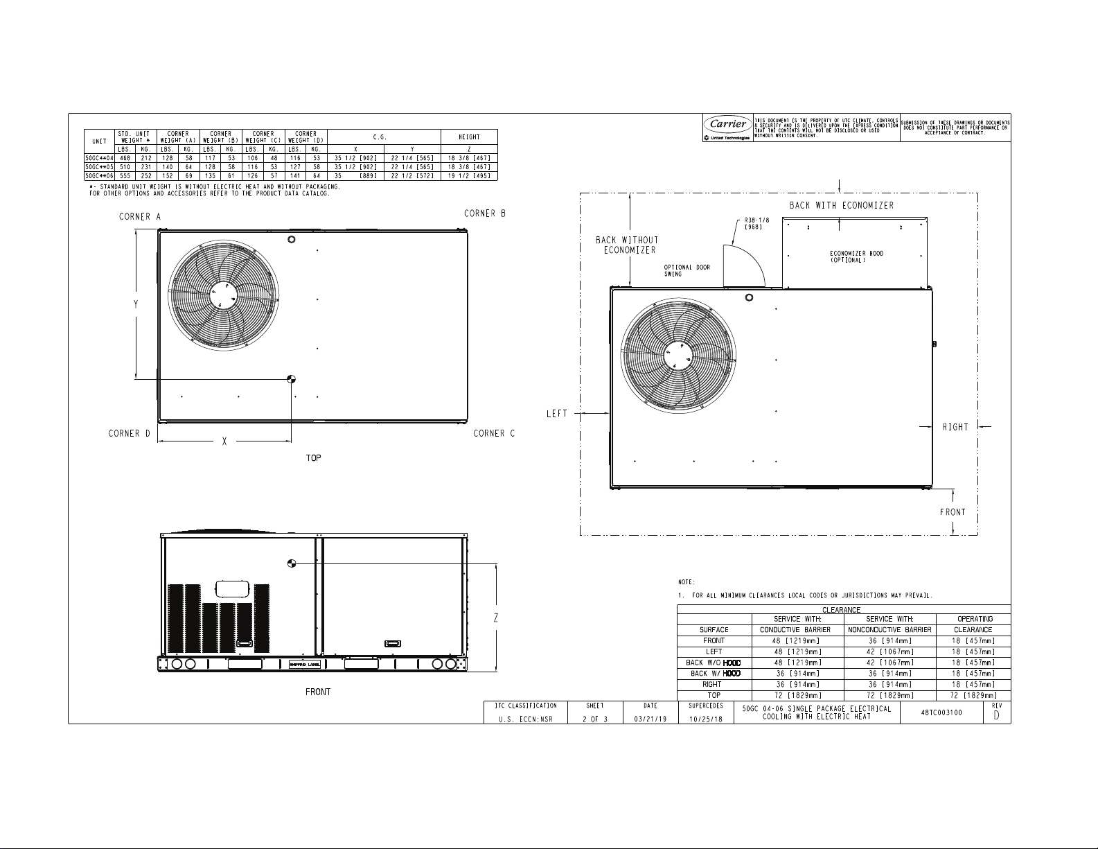
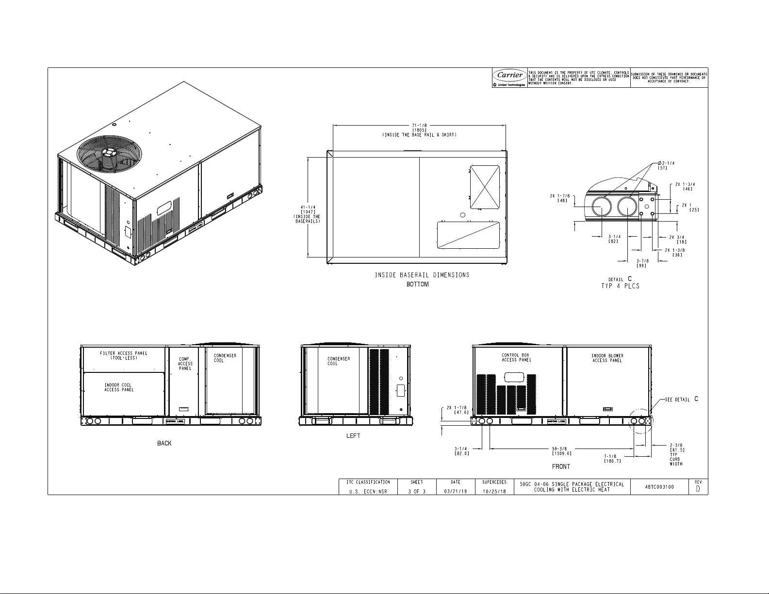
See Fig. 1 for 50GC model number nomenclature. See Fig. 2 for
unit dimensional drawings and service clearance dimensions.
Rated Indoor Airflow
Table 1 lists the rated indoor airflow used for the AHRI efficiency
rating for the units covered in this document.
Table 1 — Rated Indoor Airflow
MODEL NUMBER RATED INDOOR AIRFLOW (CFM)
50GC*N/M/P04 1200
50GC*N/M/P05 1400
50GC*N/M/P06 2000
2
Page 3
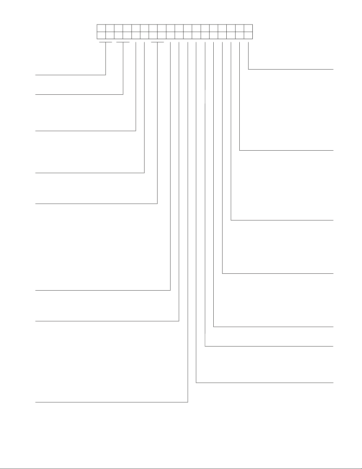
50GC–M04A1 A5–0A0A 0
Cooling Tons
04 - 3 ton
05 - 4 ton
06 - 5 ton
1
Example:
Position: 2 3 4 5 6 7 8 9
10
11 12 13 14 15 16 17 18
Heat Options
–
= No Heat
A = Low Electric Heat
B = Medium Electric Heat
C = High Electric Heat
Sens or Options
A = None
B = RA (Return Air) Smoke Detector
C = SA (Supply Air) Smoke Detector
D = RA + SA Smoke Detector
E = CO
2
F = RA Smoke Detector and CO
2
G = SA Smoke Detector and CO
2
H = RA + SA Smoke Detector and CO
2
J = Condensate Overflow Switch
K = Condensate Overflow Swtich and RA Smoke Detectors
L = Condensate Overflow Switch and RA and SA Smoke
Detectors
M = Condensate Overflow Swtich and SA Smoke Detectors
Indoor Fan Options
1 = Direct Drive
– EcoBlue – Standard Static
2 = Direct Drive
– EcoBlue – Medium Static
3 = Direct Drive
– EcoBlue – High Static
Coil Options (RTPF) (Outdoor - Indoor - Hail Guard)
A = Al/Cu - Al/Cu
B = Precoat Al/Cu - Al/Cu
C = E-coat Al/Cu - Al/Cu
D = E-coat Al/Cu - E-coat Al/Cu
E = Cu/Cu - Al/Cu
F = Cu/Cu - Cu/Cu
M = Al/Cu - Al/Cu — Louvered Hail Guard
N = Precoat Al/Cu - Al/Cu — Louvered Hail Guard
P = E-coat Al/Cu - Al/Cu — Louvered Hail Guard
Q = E-coat Al/Cu - E-coat Al/Cu — Louvered Hail Guard
R = Cu/Cu - Al/Cu — Louvered Hail Guard
S = Cu/Cu - Cu/Cu — Louvered Hail Guard
Voltage
1 = 575/3/60
3 = 208-230/1/60
5 = 208-230/3/60
6 = 460/3/60
Design Revision
– = Factory Design Revision
Base Unit Controls
0 = Electro-mechanical controls - can be used with
field-installed W7212 EconoMi$er
®
IV
(Non-Fault Detection and Diagnostic)
2 = RTU Open Multi-Protocol Controller
3 = SystemVu™ Controller
6 = Electro-mechanical - can be used with W7220
EconoMi$er X
(with Fault Detection and Diagnostic)
Intake / Exhaust Options
A = None
B = Temperature Economizer w/ Barometric Relief
F = Enthalpy Economizer w/ Barometric Relief
U = Temperature Ultra Low Leak Economizer w/
Barometric Relief
W = Enthalpy Ultra Low Leak Economizer w/
Barometic Relief
Service Options
0 = None
1 = Unpowered Convenience Outlet
2 = Powered Convenience Outlet
3 = Hinged Panels
4 = Hinged Panels and
Unpowered Convenience Outlet
5 = Hinged Panels and
Powered Convenience Outlet
6 = MERV 8 Filters
C = Foil Faced Insulation
Factory Assigned
0 = Standard
1 = LTL
Electrical Options
A = None
B = HACR Breaker
C = Non-Fused Disconnect (NFD)
D = Thru-The-Base Connections (TTB)
E = HACR and Thru-The-Base Connections
F = Non-Fused Disconnect and TTB
N = Phase Monitor Protection
P = Phase Monitor and HACR
Q = Phase Monitor and NFD
R = Phase Monitor and TTB
S = Phase Monitor and HACR and TTB
T = Phase Monitor and NFD and TTB
Refrig. Systems Options
M = Two Stage Cooling Models
N = Two Stage Cooling Models with Humidi-MiZer
®
system (includes Low Ambient control)
P = Two Stage Cooling Models with
Low Ambient control
Note: On single phase (-3 voltage code) models, the
following are not available as factory-installed options:
- Humidi-MiZer
®
System
- Coated Coils or Cu Fin Coils
- Louvered Hail Guards
- Economizer
- Powered 115 Volt Convenience Outlet
Model Series - WeatherMaster
®
GC - 16.1 SEER Efficiency
Unit Heat Type
50 - Electric Heat
Packaged Rooftop
Fig. 1 — 50GC 04-06 Model Number Nomenclature (Example)
3
Page 4
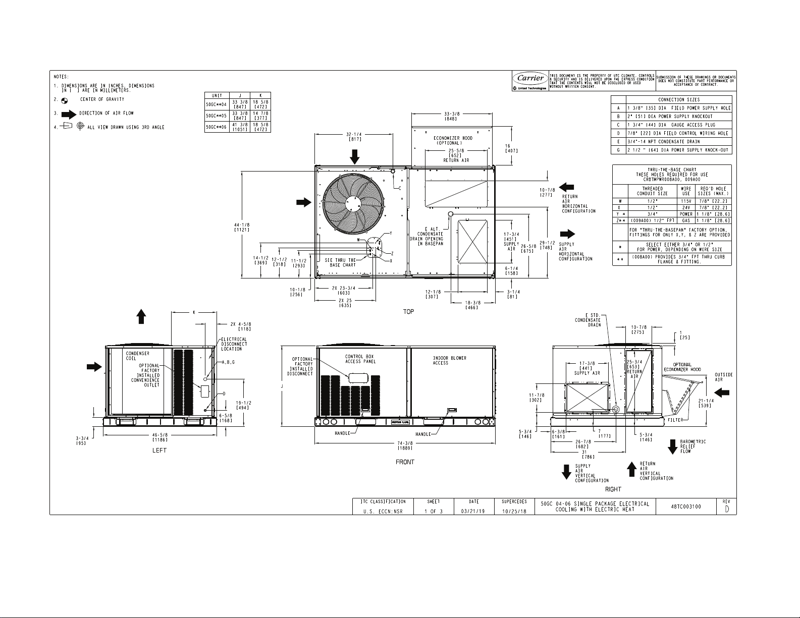
4
Fig. 2 — 50GC 04-06 Unit Dimensional Drawing
Page 5
5
Fig. 2 — 50GC 04-06 Unit Dimensional Drawing (cont)
Page 6
6
Fig. 2 — 50GC 04-06 Unit Dimensional Drawing (cont)
Page 7
INSTALLATION
Jobsite Survey
Complete the following checks before installation.
1. Consult local building codes and the NEC (National Elec-
trical Code) ANSI/NFPA 70 for special installation
requirements.
2. Determine unit location (from project plans) or select unit
location.
3. Check for possible overhead obstructions which may interfere with unit lifting or rigging.
Step 1 — Plan for Unit Location
Select a location for the unit and its support system (curb or other)
that provides for the minimum clearances required for safety (including clearance to combustible surfaces), unit performance and
service access below, around and above unit as specified in unit
drawings. See Fig. 2 on page 5.
NOTE: Consider also the effect of adjacent units.
Unit may be installed directly on wood flooring or on Class A, B,
or C roof-covering material when roof curb is used.
Do not install unit in an indoor location. Do not locate air inlets
near exhaust vents or other sources of contaminated air.
Although unit is weatherproof, avoid locations that permit water
from higher level runoff and overhangs to fall onto unit.
Select a unit mounting system that provides adequate height to al-
low installation of condensate trap per requirements. Refer to
Step 10 — Install External Condensate Trap and Line on page 12
for required trap dimensions.
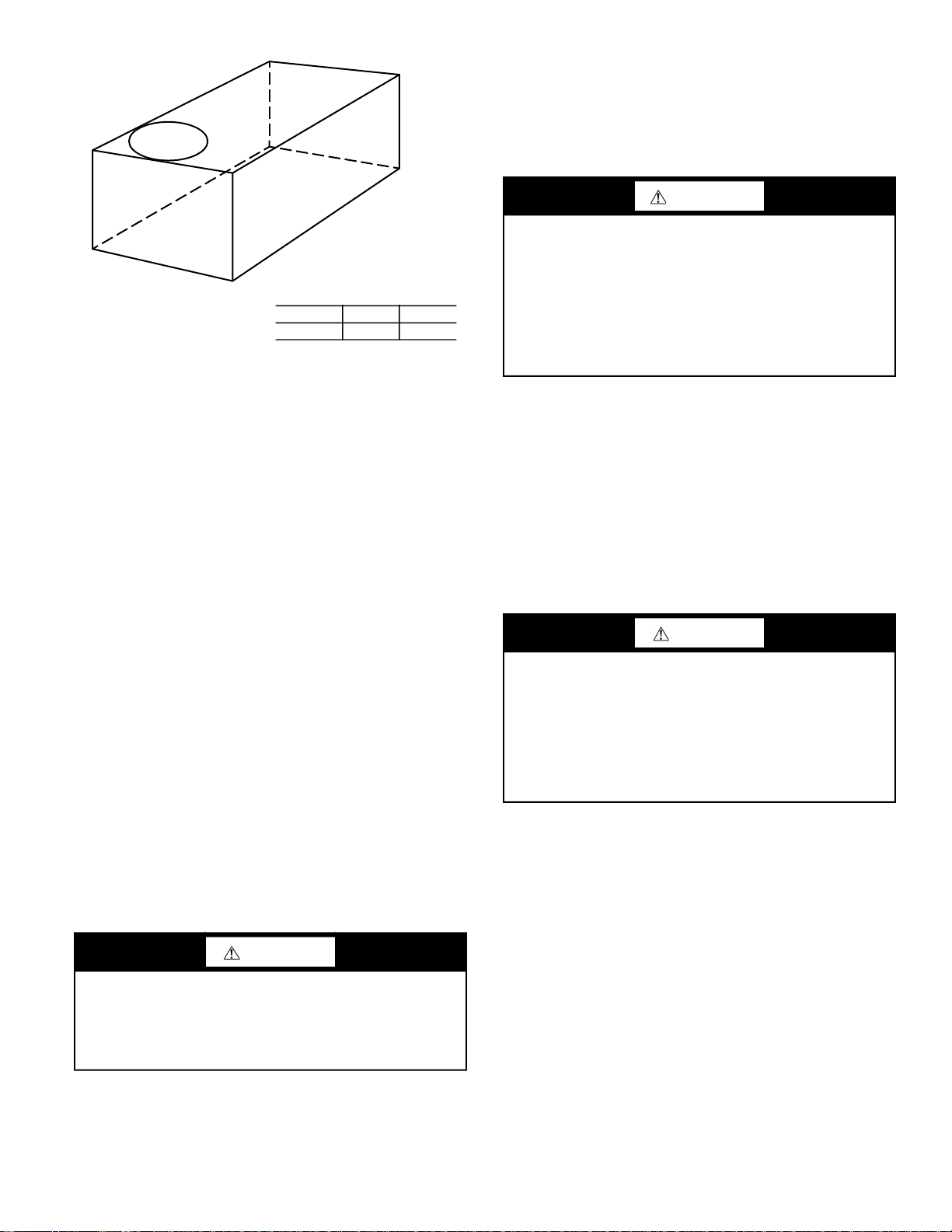
ROOF MOUNT
Check building codes for weight distribution requirements. Unit
operating weight is shown in Table 2.
Table 2 — Operating Weights
50GC-*
Base Unit 468 (212) 510 (231) 555 (252)
Economizer
Vertical 50 (23) 50 (23) 50 (23)
Horizontal 80 (36) 80 (36) 80 (36)
Humidi-MiZer
Cu Fins 25 (11) 43 (20) 56 (25)
Powered Outlet 32 (15) 32 (15) 32 (15)
Curb
14-in. (356 mm) 110 (50) 110 (50) 110 (50)
24-in. (610 mm) 145 (66) 145 (66) 145 (66)
®
System 27 (10) 34 (13) 34 (13)
UNIT LB (KG)
04 05 06
Step 2 — Plan for Sequence of Unit Installation
The support method used for this unit will dictate different sequences for the steps of unit installation. For example, on curbmounted units, some accessories must be installed on the unit before the unit is placed on the curb. Review the following for recommended sequences for installation steps:
CURB-MOUNTED INSTALLATION
1. Install curb
2. Install field-fabricated ductwork inside curb
3. Install accessory thru-base service connection package
(affects curb and unit) (refer to accessory installation instructions for details)
4. Prepare bottom condensate drain connection to suit planned
condensate line routing (refer to Step 10 — Install External
Condensate Trap and Line on page 12 for details)
5. Rig and place unit
6. Install outdoor air hood
7. Install condensate line trap and piping
8. Make electrical connections
9. Install other accessories
PAD-MOUNTED INSTALLATION
1. Prepare pad and unit supports
2. Check and tighten the bottom condensate drain connection
plug
3. Rig and place unit
4. Convert unit to side duct connection arrangement
5. Install field-fabricated ductwork at unit duct openings
6. Install outdoor air hood
7. Install condensate line trap and piping
8. Make electrical connections
9. Install other accessories
FRAME-MOUNTED INSTALLATION
Frame-mounted applications generally follow the sequence for a
curb installation. Adapt the sequence as required to suit specific
installation plan.
Step 3 — Inspect Unit
Inspect unit for transportation damage. File any claim with transportation agency.
Confirm before installation of unit that voltage, amperage and circuit protection requirements listed on unit data plate agree with
power supply provided.
On units with hinged panel option, check to be sure all latches are
snug and in closed position.
Locate the carton containing the outside air hood parts. Do not
remove carton until unit has been rigged and located in final
position.
Step 4 — Provide Unit Support
ROOF CURB MOUNT
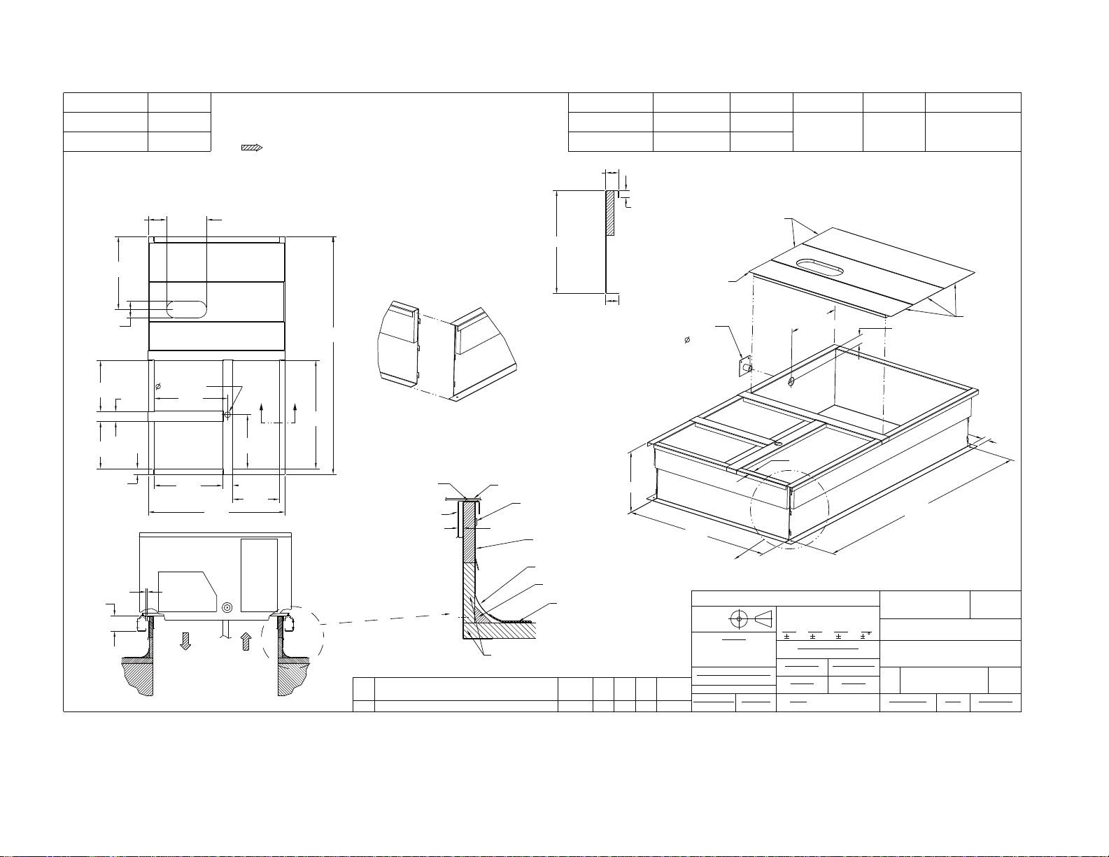
Accessory roof curb details and dimensions are shown in Fig. 3.
Assemble and install accessory roof curb in accordance with instructions shipped with the curb.
Curb should be level. This is necessary for unit drain to function
properly. Unit leveling tolerances are shown in Fig. 4. Refer to
Accessory Roof Curb Installation Instructions for additional information as required.
Install insulation, cant strips, roofing felt, and counter flashing as
shown. Ductwork must be attached to curb and not to the unit. The
accessory thru-the-base power connection package must be installed before the unit is set on the roof curb.
If electric and control wiring is to be routed through the basepan,
attach the accessory thru-the-base service connections to the basepan in accordance with the accessory installation instructions.
NOTE: The gasketing of the unit to the roof curb is critical for a
watertight seal. Install gasket supplied with the roof curb as shown
in Fig. 3. Improperly applied gasket can also result in air leaks and
poor unit performance.
7
Page 8
ROOF CURB
ACCESSORY #
CRRFCURB001A01
[137.7]
5.42"
A
14"
[356]
24"
[610]
11.96"
[303.8]
NOTES:
1. ROOFCURB ACCESSORY IS SHIPPED DISASSEMBLED.
2. INSULATED PANELS: 25.4 [1"] THK. POLYURETHANE FOAM, 44.5 [1-3/4] # DENSITY.
3. DIMENSIONS IN [ ] ARE IN MILLIMETERS.
4. ROOFCURB: 18 GAGE STEEL.
5. ATTACH DUCTWORK TO CURB. (FLANGES OF DUCT REST ON CURB).
6. SERVICE CLEARANCE 4 FEET ON EACH SIDE.
7. DIRECTION OF AIR FLOW.
8. CONNECTOR PACKAGE CRBTMPWR001A01 IS FOR THRU-THE-CURB GAS TYPE
PACKAGE CRBTMPWR003A01 IS FOR THRU-THE-BOTTOM TYPE GAS CONNECTIONS.
CONNECTOR PKG. ACC. GAS CONNECTION TYPE GAS FITTING
CRBTMPWR001A01 3/4" [19] NPT
CRBTMPWR003A01 THRU THE BOTTOM
1-3/4"
[44.5]
1.00"
[25.4]
THRU THE CURB
1/2" [12.7] NPTCRRFCURB002A01
11 3/4"[298.5] WIDE
INSULATED DECK PANELS
POWER WIRING
FITTING
3/4" [19] NPT
CONTROL WIRING
FITTING
1/2" [12.7] NPT 1/2" [12.7] NPT
ACCESSORY CONVENIENCE
OUTLET WIRING CONNECTOR
"A"
21.74"
[552.2]
4.96"
[126.0]
RETURN AIR
40.69"
[1033.5]
OPENING
16.03"
[407.2]
3.00"
[76.2]
13.78"
[350.0]
E
15.19"
[385.8]
8
14.00"
[355.6]
1.75"
[44.5]
1/4"
[7.0]
4 9/16"
[115.5]
3.00"
[76.2]
1/3/4"[44.5]
21.84"
[554.7]
SUPPLY AIR
OPENING
20.41"
[518.3]
SUPPLY AIR RETURN AIR
70.87"
[1800.2]
E
32.19"
[817.6]
(SUPPLIED WITH CURB)
OVERALL DIM. 5'-7 3/8" WAS 5'-7 7/8; 18GA
MATERIAL WA 16 GA.; NAIL FIELD SUPPLIED WAS
A
WITH CURB
VIEW "B"
CORNER DETAIL
GASKET
DUCT
(FIELD SUPPLIED)
UNIT
NAIL (FIELD SUPPLIED)
TYPICAL (4) SIDES
7/16"
[11]
COUNTER FLASHING
(FIELD SUPPLIED)
RIGID INSULATION
(FIELD SUPPLIED)
ROOFING FELT
(FIELD SUPPLIED)
CANT STRIP
(FIELD SUPPLIED)
ROOFING MATERIAL
(FIELD SUPPLIED)
E-ESECTION
SCALE 0.250
1-3/4"
[44.4]
"A"
8 9/16"[217.5] WIDE
INSULATED DECK PANEL
GAS SERVICE PLATE
THRU THE CURB
DRILL HOLE
2" [50.8] @
ASSEMBLY (IF
REQUIRED)
(SEE NOTE #8)
SUPPLY AIR
3'-1 3/16"
[944.6]
SEE VIEW "B"
DRAWING RELEASE LEVEL:
THIRD ANGLE
PROJECTION
ENGINEERING REQUIREMENTS
1067898--MMC04/22/13
SURFACE FINISH MFG/PURCH MODEL (INTERNAL USE ONLY) NEXT DRAWING SCALE DISTRIBUTION
ECN NO.APP'DCHK'DBYDATEREVISION RECORDREV
1' 4-13/16"
[427] INSIDE
RETURN AIR
1-3/4"
[44.5]
2-3/8"
[61]
5' 7-3/8"
[1711.3]
SEE NOTE #2
CERTIFIED DRAWING
PRODUCTION
UNLESS OTHERWISE SPECIFIED
DIMENSIONS ARE IN INCHES
TOLERANCES ON:
MATERIAL
-
-
-
T-005, Y-002
WEIGHT:
-
- PURCH - N/A MMC
1 DEC 2 DEC 3 DEC ANG
----
AUTHORIZATION NUMBER TITLE
1041738
ENGINEERING MANUFACTURING
-
MMC 06/17/11 - -
-
-
DRAFTER CHECKER
CURB ASY, ROOF
SIZE DRAWING NUMBER REV
-
48TC400427
D
SHEET 5 OF 5
1-3/4"
[44.4]
B
Fig. 3 — Roof Curb Details
Page 9
A
B
C
MAXIMUM ALLOWABLE
DIFFERENCE IN. (MM)
A-B B-C A-C
0.5 (13) 1.0 (25) 1.0 (25)
Fig. 4 — Unit Leveling Tolerances
SLAB MOUNT (HORIZONTAL UNITS ONLY)
Provide a level concrete slab that extends a minimum of 6-in.
(150 mm) beyond unit cabinet. Install a gravel apron in front of
condenser coil air inlet to prevent grass and foliage from obstructing airflow.
NOTE: Horizontal units may be installed on a roof curb if
required.
ALTERNATE UNIT SUPPORT (IN LIEU OF CURB OR SLAB MOUNT)
A non-combustible sleeper rail can be used in the unit curb support area. If sleeper rails cannot be used, support the long sides of
the unit with a minimum of 3 equally spaced 4-in. x 4-in. (102 mm
x 102 mm) pads on each side.
Step 5 — Field Fabricate Ductwork
Cabinet return-air static pressure (a negative condition) shall not
exceed 0.35 in. wg (87 Pa) with economizer or 0.45 in. wg
(112 Pa) without economizer.
For vertical ducted applications, secure all ducts to roof curb and
building structure. Do not connect ductwork to unit.
Fabricate supply ductwork so that the cross sectional dimensions
are equal to or greater than the unit supply duct opening dimensions for the first 18-in. (458 mm) of duct length from the unit
basepan.
Insulate and weatherproof all external ductwork, joints, and roof
openings with counter flashing and mastic in accordance with applicable codes.
Ducts passing through unconditioned spaces must be insulated
and covered with a vapor barrier.
If a plenum return is used on a vertical unit, the return should be
ducted through the roof deck to comply with applicable fire codes.
CAUTION
PROPERTY DAMAGE HAZARD
Failure to follow this caution may result in damage to roofing
materials.
Membrane roofs can be cut by sharp sheet metal edges. Be
careful when placing any sheet metal parts on such roof.
UNITS WITH ACCESSORY OR OPTIONAL ELECTRIC HEATERS
All installations require a minimum clearance to combustible surfaces of 1-in. (25 mm) from duct for first 12-in. (305 mm) away
from unit.
Outlet grilles must not lie directly below unit discharge.
WARNING
PERSONAL INJURY HAZARD
Failure to follow this warning could cause personal injury.
For vertical supply and return units, tools or parts could drop
into ductwork and cause an injury. Install a 90 degree turn in
the return ductwork between the unit and the conditioned
space. If a 90 degree elbow cannot be installed, then a grille of
sufficient strength and density should be installed to prevent
objects from falling into the conditioned space. Due to electric
heater, supply duct will require 90 degree elbow.
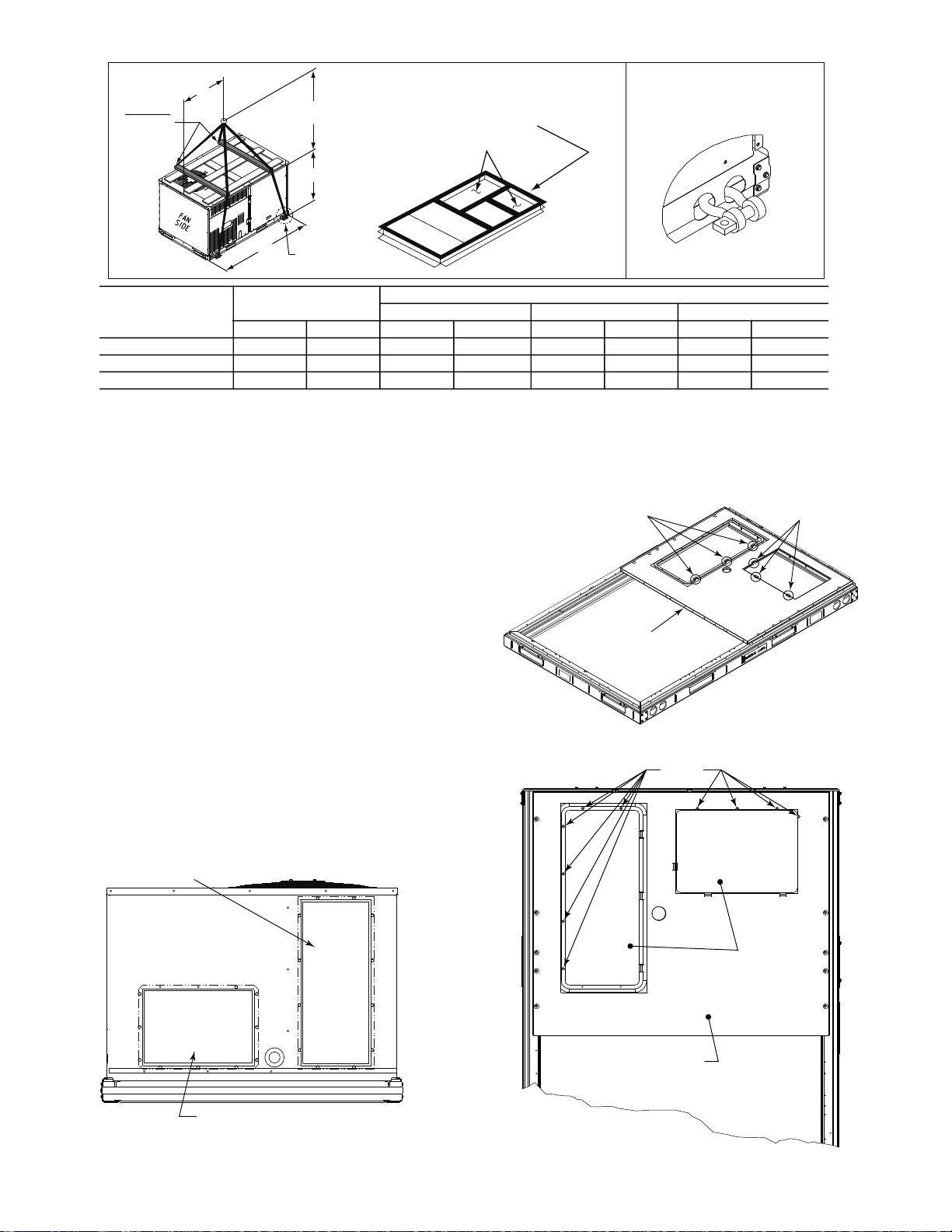
Step 6 — Rig and Place Unit
Keep unit upright and do not drop. Spreader bars are required.
Rollers may be used to move unit across a roof. Rigging materials
under unit (cardboard or wood) must be removed PRIOR to placing the unit on the roof curb. Level by using unit frame as a reference. See Table 2 on page 7 and Fig. 5 for additional information.
Lifting holes are provided in base rails as shown in Fig. 5. Refer to
rigging instructions on unit.
Rigging materials under the unit (cardboard or wood to prevent
base pan damage) must be removed PRIOR to placing the unit on
the roof curb.
Before setting the unit onto the curb, recheck gasketing on curb.
.
CAUTION
UNIT DAMAGE HAZARD
Failure to follow this caution may result in equipment damage.
All panels must be in place when rigging. Unit is not designed
for handling by fork truck when packaging is removed.
If using top crate as spreader bar, once unit is set, carefully
lower wooden crate off building roof top to ground. Ensure
that no people or obstructions are below prior to lowering the
crate.
POSITIONING ON CURB
Position unit on roof curb so that the following clearances are
maintained:
the base rail inside the front and rear, 0.0-in. clearance between the
roof curb and the base rail inside on the duct end of the unit. This
will result in the distance between the roof curb and the base rail
inside on the condenser end of the unit being approximately
(6.4 mm).
Although unit is weatherproof, guard against water from higher
level runoff and overhangs.
After unit is in position, remove rigging skids and shipping
materials.
1
/4-in. (6.4 mm) clearance between the roof curb and
1
/4-in.
9
Page 10
.
DETAIL "A"
PLACE ALL SEAL STRIP IN PLACE
BEFORE PLACING UNIT ON ROOF CURB.
DUCT END
SEE DETAIL "A"
"A"
(914-1371)
36"- 54"
"C"
"B"
SPREADER
BARS
REQUIRED
REMOVABLE HORIZONTAL
SUPPLY DUCT OPENING COVER
REMOVABLE HORIZONTAL
RETURN DUCT OPENING COVER
SCREWS
DUCT COVERS
SHEET METAL
FACE UP
BASEPAN
UNIT
50GC-*04 780 354 74.5 1890 35.5 900 33.5 850
50GC-*05 863 391 74.5 1890 35.5 900 33.5 850
50GC-*06 969 440 74.5 1890 35.0 890 41.5 1055
NOTES:
1. SPREADER BARS REQUIRED — Top damage will occur if spreader bars are not used.
2. Dimensions in ( ) are in millimeters.
3. Hook rigging shackles through holes in base rail, as shown in detail “A.” Holes in base rails are centered around the unit center of
gravity. Use wooden top to prevent rigging straps from damaging unit.
MAX WEIGHT
lb kg in. mm in. mm in. mm
Fig. 5 — Rigging Details
Step 7 — Convert to Horizontal and Connect
Ductwork (When Required)
Unit is shipped in the vertical duct configuration. Unit without
factory-installed economizer or return-air smoke detector option
may be field-converted to horizontal ducted configuration. To
convert to horizontal configuration, remove screws from side duct
opening covers (see Fig. 6) and remove covers. Use the screws to
install the covers on vertical duct openings with the insulation-side
down. The panels must be inserted into the notches on the basepan
to properly seal. The notches are covered by the tape used to
secure the insulation to the basepan and are not easily seen. See
Fig. 7 for position of the notches in the basepan. Seals around duct
openings must be tight. Secure with screws as shown in Fig. 8.
Cover seams with foil duct tape.
Field-supplied flanges should be attached to horizontal duct
openings and all ductwork should be secured to the flanges.
Insulate and weatherproof all external ductwork, joints, and roof
or building openings with counter flashing and mastic in
accordance with applicable codes.
Do not cover or obscure visibility to the unit’s informative data
plate when insulating horizontal ductwork.
DIMENSIONS
A B C
NOTCHES
BASEPAN
Fig. 7 — Location of Notches
NOTCHES
Fig. 6 — Horizontal Conversion Panels
10
Fig. 8 — Horizontal Duct Panels In Place
Page 11
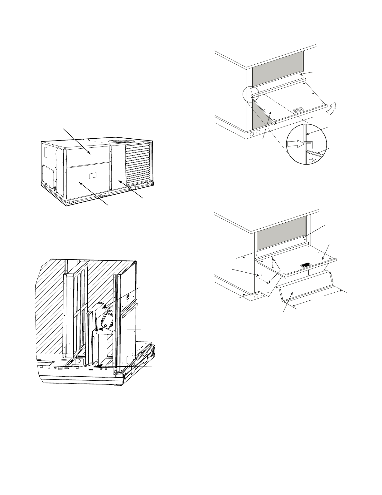
Step 8 — Install Outside Air Hood
HOOD PARTS
PLASTIC TIE WRAP
QTY (2)
SCREWS FOR
METAL TRAY
QTY (2)
ECONOMIZER HOOD PACKAGE REMOVAL AND SETUP (FACTORY OPTION)
NOTE: Economizer is not available as factory-installed options
for single phase (-3 voltage code) models.
The hood is shipped in knock-down form and must be field assembled. The indoor coil access panel is used as the hood top
while the hood sides, divider and filter are packaged together, attached to a metal support tray using plastic stretch wrap, and
shipped in the return air compartment behind the indoor coil access panel. The hood assembly’s metal tray is attached to the basepan and also attached to the damper using two plastic tie-wraps.
1. To gain access to the hood, remove the filter access panel. See
Fig. 9.
FILTER ACCESS PANEL
COMPRESSOR
ACCESS PANEL
OUTDOOR-AIR OPENING AND
INDOOR COIL ACCESS PANEL
Fig. 9 — Typical Access Panel Locations
2. Locate the (2) screws holding the metal tray to the basepan
and remove. Locate and cut the (2) plastic tie-wraps securing
the assembly to the damper. See Fig. 10. Avoid damaging any
wiring or cutting tie-wraps securing any wiring.
1. The indoor coil access panel will be used as the top of the
hood. Remove the screws along the sides and bottom of the
indoor coil access panel. See Fig. 11.
TOP
PAN EL
TOP
PAN EL
INDOOR
COIL
ACCESS
PAN EL
INDOOR
COIL
ACCESS
PAN EL
CAULK
HERE
Fig. 11 — Indoor Coil Access Panel Relocation
2. Swing out indoor coil access panel and insert the hood sides
under the panel (hood top). Use the screws provided to attach
the hood sides to the hood top. Use screws provided to attach
the hood sides to the unit. See Fig. 12.
TOP
PAN EL
INDOOR COIL
ACCESS PANEL
Fig. 10 — Economizer Hood Parts Location
3. Carefully lift the hood assembly (with metal tray) through the
filter access opening and assemble per the steps outlined in
the following section, “Economizer Hood”.
ECONOMIZER HOOD
NOTE: If the power exhaust accessory is to be installed on the
unit, the hood shipped with the unit will not be used and must be
discarded. Save the aluminum filter for use in the power exhaust
hood assembly.
LEFT
HOOD
SIDE
19 1/16”
B
(483mm)
SCREW
HOOD DIVIDER
33 3/8”
(848mm)
Fig. 12 — Economizer Hood Construction
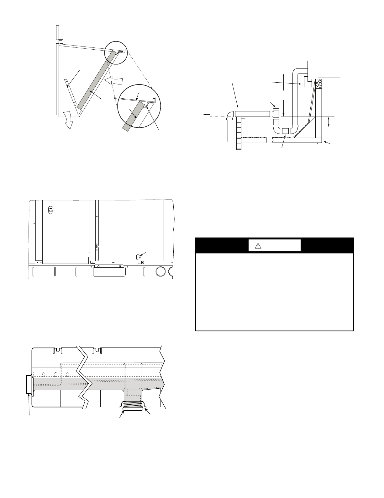
3. Remove the shipping tape holding the economizer barometric
relief damper in place (economizer only).
4. Insert the hood divider between the hood sides. See Fig. 12
and 13. Secure hood divider with 2 screws on each hood side.
The hood divider is also used as the bottom filter rack for the
aluminum filter.
5. Open the filter clips which are located underneath the hood
top. Insert the aluminum filter into the bottom filter rack
(hood divider). Push the filter into position past the open filter
clips. Close the filter clips to lock the filter into place. See
Fig. 13.
6. Caulk the ends of the joint between the unit top panel and the
hood top.
7. Replace the filter access panel.
11
Page 12
To use the alternate bottom drain connection, remove the red drain
DIVIDER
BAROMETRIC
RELIEF
CLEANABLE
ALUMINUM
FILTER
FILTER
HOOD
FILTER
CLIP
OUTSIDE
AIR
DRAIN
(FACTORY-INSTALLED)
PLUG
CONDENSATE PAN (SIDE VIEW)
STANDARD
SIDE DRAIN
ALTERNATE
BOTTOM DRAIN
plug from the bottom connection (use a
1
/2-in. square socket drive
extension) and install it in the side drain connection.
The piping for the condensate drain and external trap can be com-
pleted after the unit is in place. See Fig. 16.
MINIMUM PITCH
1˝ (25 mm) PER
10´ (3 m) OF LINE
BASE RAIL
OPEN
VENT
3˝ (76 mm)
MIN
Fig. 13 — Economizer Filter Installation
Step 9 — Units with Hinged Panels Only
Relocate latch shipped inside the compressor compartment behind
the hinged compressor door to location shown in Fig. 14 after unit
installation.
If the unit does not have hinged panels, skip this step and continue
at Step 10 below.
COMPRESSOR
DOOR
OUTDOOR COIL
LATCH
Fig. 14 — Compressor Door Latch Location
Step 10 — Install External Condensate Trap and
Line
The unit has one 3/4-in. condensate drain connection on the end of
the condensate pan and an alternate connection on the bottom. See
Fig. 15. Unit airflow configuration does not determine which
drain connection to use. Either drain connection can be used with
vertical or horizontal applications.
Fig. 15 — Condensate Drain Pan (Side View)
When using the standard side drain connection, ensure that the red
plug in the alternate bottom connection is tight. Do this before setting the unit in place. The red drain pan plug can be tightened with
1
a
/2-in. square socket drive extension.
TO ROO F
DRAIN
DRAIN PLUG
NOTE: Trap should be deep enough to offset maximum unit static
difference. A 4-in. (102 mm) trap is recommended.
SEE NOTE
ROOF
CURB
Fig. 16 — Condensate Drain Pan Piping Details
All units must have an external trap for condensate drainage. Install a trap at least 4-in. (102 mm) deep and protect against
freeze-up. If drain line is installed downstream from the
external trap, pitch the line away from the unit at 1-in. per 10 ft
(25 mm per 3 m) of run. Do not use a pipe size smaller than the
unit connection (
3
/4-in.).
Step 11 — Make Electrical Connections
WARNING
ELECTRIC SHOCK HAZARD
Failure to follow this warning could result in personal injury or
death.
Unit cabinet must have an uninterrupted, unbroken electrical
ground to minimize the possibility of personal injury if an
electrical fault should occur. This ground may consist of
electrical wire connected to unit ground lug in control
compartment, or conduit approved for electrical ground when
installed in accordance with NEC; ANSI/NFPA 70, latest
edition (in Canada, Canadian Electrical Code CSA [Canadian
Standards Association] C22.1), and local electrical codes.
NOTE: Field-supplied wiring shall conform with the limitations
of minimum 63°F (33°C) rise.
FIELD POWER SUPPLY
If equipped with optional powered convenience outlet, the power
source leads to the convenience outlet’s transformer primary are
not factory connected. Installer must connect these leads according to required operation of the convenience outlet. If an alwaysenergized convenience outlet operation is desired, connect the
source leads to the line side of the unit-mounted disconnect.
(Check with local codes to ensure this method is acceptable in
your area.) If a de-energize via unit disconnect switch operation of
the convenience outlet is desired, connect the source leads to the
load side of the unit disconnect. On a unit without a unit-mounted
disconnect, connect the source leads to compressor contactor C
and indoor fan contactor IFC pressure lugs with unit field power
leads. See Convenience Outlets on page 15 for power transformer
connections.
The field power wires are connected to the unit at line-side pressure lugs on compressor contactor C and indoor fan contactor IFC
(see wiring diagram label for control box component
12
Page 13
arrangement) or at factory-installed option non-fused disconnect
COPPER
WIRE ONLY
ELECTRIC
DISCONNECT
SWITCH
ALUMINUM
WIRE
switch or HACR. Maximum wire size is #2ga AWG (copper only)
per pole on contactors, #2ga AWG (copper only) per pole on optional disconnect or HACR, and 4/0 AWG (copper only) per pole
on terminal or fuse blocks on units with single point box (see
Fig. 17). See Fig. 18 and unit label diagram for field power wiring
connections.
NOTE: Unit may be equipped with short test leads (pigtails) on
the field line connection points on contactor C or optional disconnect switch. These leads are for factory-run test purposes only; remove and discard before connecting field power wires to unit connection points. Make field power connections directly to line connection pressure lugs only.
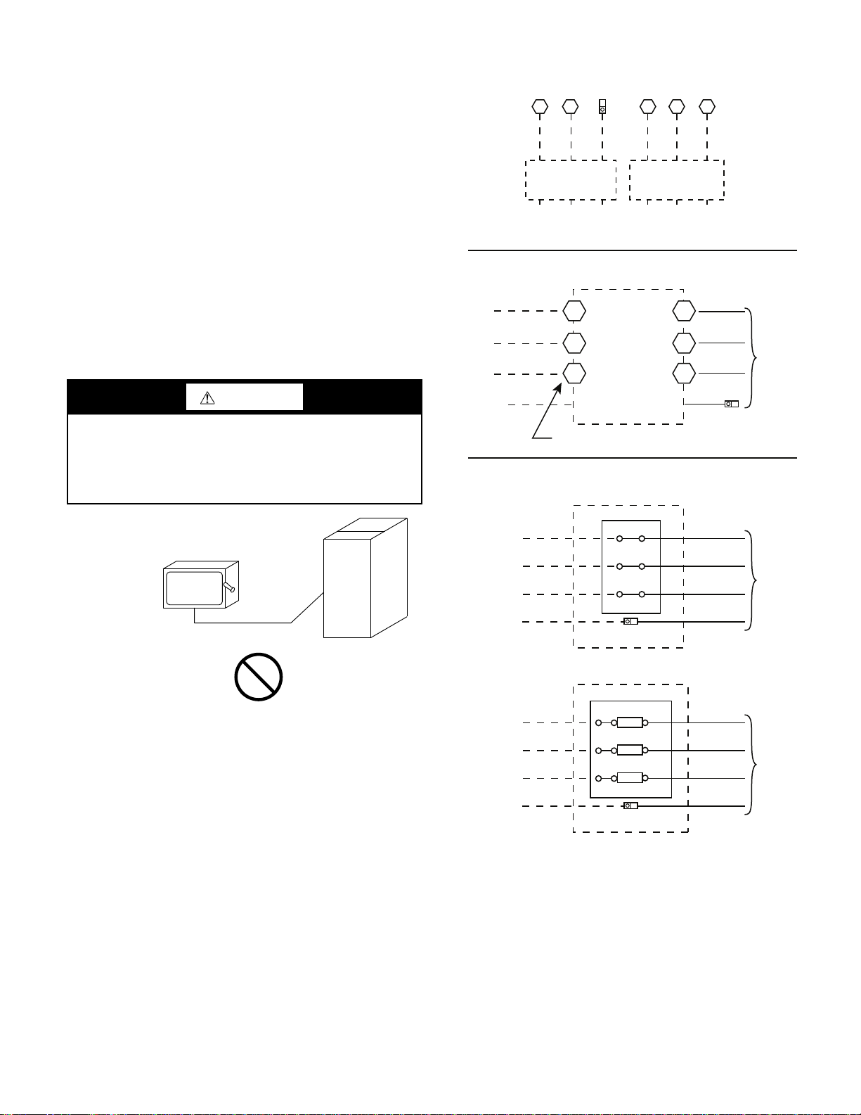
UNITS WITH FACTORY-INSTALLED NON-FUSED DISCONNECT OR HACR
The factory-installed optional non-fused disconnect (NFD) or
HACR switch is located in a weatherproof enclosure located under the main control box. The manual switch handle and shaft are
shipped in the disconnect or HACR enclosure. Assemble the shaft
and handle to the switch at this point. Discard the factory test leads
(see Fig. 18).
Units Without Single Point Box, Disconnect or HACR Option
Equip
GR Lug
TB TB
11 12
Disconnect
per
NEC
208/230-1-60
Ground
(GR)
11 12 13
Disconnect
per
NEC
L1 L2 L3
208/230-3-60
460-3-60
575-3-60
Units With Disconnect or HACR Option
L1
L2
3 Phase Only 3 Phase Only
L3
2
Optional
Disconnect
4
6
Switch
1
3
5
Factory
Wiring
WARNING
FIRE HAZARD
Failure to follow this warning could result in personal injury,
death, or property damage.
Do not connect aluminum wire between disconnect switch and
unit. Use only copper wire.
Fig. 17 — Disconnect Switch and Unit
Connect field power supply conductors to LINE side terminals
when the switch enclosure cover is removed to attach the handle.
Ground
(GR)
Disconnect factory test leads; discard.
Equip GR Lug
Units With Electric Heat Option with Single Point Box
and Without Disconnect or HACR Option
Single Point Box
L1
L2
L3
Ground (GR)
Terminal Block
Equip GR
Lug
— OR —
Single Point Box
L1
L2
L3
Ground (GR)
Fuse/Terminal Block
Fuse
Fuse
Fuse
Equip GR
Lug
Fig. 18 — Power Wiring Connections
Factory
Wiring
Factory
Wiring
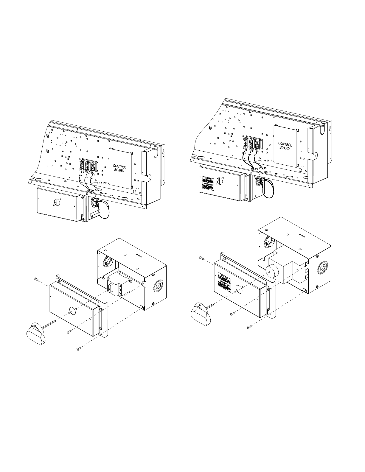
Field-Install the NFD Shaft and Handle
1. Remove the Control Box access panel. The NFD enclosure is
located below the Control Box (see Fig. 19).
2. Remove (3) cap head screws that secure the NFD enclosure
front cover — (2) on the face of the cover and (1) on the left
side cover. See Fig. 20.
3. Remove the front cover of the NFD enclosure.
4. Make sure the NFD shipped from the factory is at OFF position (the arrow on the black handle knob is at OFF).
5. Insert the shaft with the cross pin on the top of the shaft in the
horizontal position. See Fig. 20.
13
Page 14
6. Measure from the tip of the shaft to the top surface of the
black pointer; the measurement should be 3.75 to 3.88-in. (95
to 99 mm).
7. Tighten the locking screw to secure the shaft to the NFD.
8. Turn the handle to the OFF position with red arrow pointing
at OFF.
9. Install the handle on to the painted cover horizontally with the
red arrow pointing to the left.
10. Secure the handle to the painted cover with (2) screws and
lock washers supplied.
11. Engaging the shaft into the handle socket, re-install (3) hex
screws on the NFD enclosure.
12. Re-install the unit front panel.
6. Tighten the locking screw to secure the shaft to the HACR.
7. Turn the handle to the OFF position with red arrow pointing
at OFF.
8. Install the handle on to the painted cover horizontally with the
red arrow pointing to the left.
9. Secure the handle to the painted cover with (2) screws and
lock washers supplied.
10. Engaging the shaft into the handle socket, re-install (3) hex
screws on the HACR enclosure.
11. Re-install the unit front panel.
Fig. 19 — NFD Enclosure Location
Fig. 20 — NFD Handle and Shaft Assembly
Field-Install the HACR Shaft and Handle
1. Remove the Control Box access panel. The HACR enclosure
is located below the Control Box (see Fig. 21).
2. Remove (3) cap head screws that secure the HACR enclosure
— (2) on the face of the cover and (1) on the left side cover.
See Fig. 22.
3. Remove the front cover of the HACR enclosure.
4. Make sure the HACR shipped from the factory is at OFF
position (the white arrow pointing at OFF).
5. Insert the shaft all the way with the cross pin on the top of the
shaft in the horizontal position. See Fig. 22.
Fig. 21 — HACR Enclosure Location
Fig. 22 — HACR Handle and Shaft Assembly
UNITS WITHOUT FACTORY-INSTALLED NON-FUSED DISCONNECT OR HACR
When installing units, provide a disconnect switch per NEC (National Electrical Code) of adequate size. Disconnect sizing data
is provided on the unit informative plate. Locate on unit cabinet
or within sight of the unit per national or local codes. Do not
cover unit informative plate if mounting the disconnect on the
unit cabinet.
ALL UNITS
All field wiring must comply with NEC and all local codes. Size
wire based on MCA (Minimum Circuit Amps) on the unit informative plate. See Fig. 18 and the unit label diagram for power wiring connections to the unit power terminal blocks and equipment
ground. Maximum wire size is #2ga AWG (copper only) per pole
on contactors, #2ga AWG (copper only) per pole on optional disconnect or HACR, and 4/0 AWG (copper only) per pole on
14
Page 15

terminal or fuse block on units with single point box. See Fig. 18
WEATHERPROOF
COVER
and unit label diagram for field power wiring connections.
Provide a ground fault and short circuit over-current protection de-
vice (fuse or breaker) per NEC Article 440 (or local codes). Refer
to unit informative data plate for MOCP (Maximum Over-Current
Protection) device size.
NOTE: Units ordered with factory installed HACR do not need an
additional ground fault and short circuit over-current protective
device unless required by local codes.
All field wiring must comply with the NEC and local
requirements.
All units except 208/230v units are factory wired for the voltage
shown on the nameplate. If the 208/230v unit is to be connected to
a 208v power supply, the control transformer must be rewired by
removing the black wire with the
from the 230v connection and moving it to the 200v
1
/4-in. female spade connector
1
/4-in. male
terminal on the primary side of the transformer. Refer to unit label
diagram for additional information. Field power wires will be
connected at line-side pressure lugs on the power terminal block
or at factory-installed option non-fused disconnect.
NOTE: Check all factory and field electrical connections for
tightness.
CONVENIENCE OUTLETS
WARNING
Fig. 24 — Convenience Outlet Utilization
Notice Label
Installing Weatherproof Cover
A weatherproof while-in-use cover for the factory-installed convenience outlets is now required by UL standards. This cover cannot
be factory-mounted due its depth; it must be installed at unit installation. For shipment, the convenience outlet is covered with a
blank cover plate.
On units with electro-mechanical controls the weatherproof cover
kit is shipped in the unit’s control box. The kit includes the hinged
cover, a backing plate and gasket.
On units with a factory installed direct digital controller (SystemVu™ controls or RTU Open controller) the weatherproof cover kit
is secured to the basepan underneath the control box. See Fig. 25.
ELECTRICAL OPERATION HAZARD
Failure to follow this warning could result in personal injury or
death.
Units with convenience outlet circuits may use multiple
disconnects. Check convenience outlet for power status before
opening unit for service. Locate its disconnect switch, if
appropriate, and open it. Lock-out and tag-out this switch, if
necessary.
Two types of convenience outlets are offered on 50GC models:
non-powered and unit-powered. Both types provide a 125-v GFCI
(ground-fault circuit interrupter) duplex receptacle rated at 15A
behind a hinged waterproof access cover, located on the end panel
of the unit. See Fig. 23.
Figure 23 shows the Convenience Outlet Utilization label which is
located below the convenience outlet.
NOTE: Unit powered convenience outlets are not available as factory installed options for single phase (-3 voltage code) models.
CONVENIENCE
OUTLET GFCI
PWD-CO
TRANSFORMER
PWD-CO FUSE
SWITCH
Fig. 23 — Convenience Outlet Location
Fig. 25 — Weatherproof Cover - Shipping Location
on Units with Factory-Installed DDC
WARNING
ELECTRICAL OPERATION HAZARD
Failure to follow this warning could result in personal injury or
death.
Using unit-mounted convenience outlets: Units with unit-
mounted convenience outlet circuits will often require that two
disconnects be opened to de-energize all power to the unit.
Treat all units as electrically energized until the convenience
outlet power is also checked and de-energization is confirmed.
Observe National Electrical Code Article 210, Branch
Circuits, for use of convenience outlets.
1. Remove the blank cover plate at the convenience outlet; dis-
card the blank cover.
2. Loosen the two screws at the GFCI duplex outlet, until
approximately
Press the gasket over the screw heads.
3. Slip the backing plate over the screw heads at the keyhole
slots and align with the gasket; tighten the two screws until
snug (do not over-tighten).
1/
-in. (13 mm) under screw heads is exposed.
2
15
Page 16

TOP
TOP
TOP
WET LOC
A
TIONS
WET LO
CATIONS
4. Mount the weatherproof cover to the backing plate as shown
in Fig. 26.
5. Remove two slot fillers in the bottom of the cover to permit
service tool cords to exit the cover.
6. Check for full closing and latching.
COVER - WHILE-IN-USE
WEATHERPROOF
BASEPLATE FOR
GFCI RECEPTACLE
GFCI RECEPTACLE
NOT INCLUDED
GASKET
Fig. 26 — Weatherproof Cover Installation
Non-Powered Convenience Outlet
This type requires the field installation of a general-purpose 125-v
15A circuit powered from a source elsewhere in the building. Observe national and local codes when selecting wire size, fuse or
breaker requirements, and disconnect switch size and location.
Route 125-v power supply conductors into the bottom of the utility box containing the duplex receptacle.
Unit-Powered Convenience Outlet
A unit-mounted transformer is factory-installed to step down the
main power supply voltage to the unit to 115-v at the duplex receptacle. This option also includes a manual switch with fuse, located in a utility box and mounted on a bracket behind the convenience outlet; access is through the unit’s control box access panel.
See Fig. 23.
The primary leads to the convenience outlet transformer are not
factory-connected. Selection of primary power source is a customer option. If local codes permit, the transformer primary leads can
be connected at the line-side terminals on the unit-mounted nonfused disconnect or HACR breaker switch; this will provide service power to the unit when the unit disconnect switch or HACR
switch is open. Other connection methods will result in the convenience outlet circuit being de-energized when the unit disconnect
or HACR switch is open. See Fig. 27.
Using Unit-Mounted Convenience Outlets
Units with unit-mounted convenience outlet circuits will often require that two disconnects be opened to de-energize all power to
the unit. Treat all units as electrically energized until the convenience outlet power is also checked and de-energization is confirmed. Observe National Electrical Code Article 210, Branch Circuits, for use of convenience outlets.
Fuse On Power Type
1
The factory fuse is a Bussman
“Fusetron” T-15, non-renewable
screw-in (Edison base) type plug fuse.
Test the GFCI receptacle by pressing the TEST button on the face
of the receptacle to trip and open the receptacle. Check for proper
grounding wires and power line phasing if the GFCI receptacle
does not trip as required. Press the RESET button to clear the
tripped condition.
1. Bussman and Fusetron are trademarks of Cooper Technologies
Company.
UNIT
VOLTAGE
208, 230 240
460 480
575 600
CONNECT ASPRIMARY
CONNECTIONS
L1: RED + YEL
L2: BLU + GRA
L1: RED
Splice BLU + YEL
L2: GRA
L1: RED
L2: GRA
TRANSFORMER
TERMINALS
H1 + H3
H2 + H4
H1
H2 + H3
H4
H1
H2
Fig. 27 — Powered Convenience Outlet Wiring
HACR AMP RATING
The amp rating of the HACR factory-installed option is based on
the size, voltage, indoor motor and other electrical options of the
unit as shipped from the factory. If field-installed accessories are
added or changed in the field (for example, power exhaust,
ERV), the HACR may no longer be of the proper amp rating and
therefore will need to be removed from the unit. See unit nameplate and label on factory-installed HACR for the amp rating of
the HACR that was shipped with the unit from the factory
(Fig. 28). See unit nameplates for the proper fuse, HACR or
maximum over-current protection device required on the unit
with field installed accessories.
Fig. 28 — HACR Caution Label
FACTORY OPTION THRU-BASE CONNECTIONS
This service connection kit consists of a 1/2-in. electrical bulkhead
connector and a 3/4-in. electrical bulkhead connector, connected to
an “L” bracket covering the embossed (raised) section of the unit
basepan in the condenser section (see Fig. 29 for shipping position).
16
Page 17

The 3/4-in. bulkhead connector enables the low-voltage control
LOW VOLTAGE
CONDUIT
CONNECTOR
HIGH VOLTAGE
CONDUIT
CONNECTOR
AUXILIARY
POWER SUPPLY
(OPTIONAL)
wires to pass through the basepan. The 1/2-in. bulkhead connector
allows the high-voltage power wires to pass through the basepan.
See Fig. 30.
Check tightness of connector lock nuts before connecting electrical conduits.
Field-supplied and field-installed liquid-tight conduit connectors
and conduit may be attached to the connectors on the basepan.
Pull correctly rated high voltage and low voltage through
appropriate conduits. Connect the power conduit to the internal
disconnect (if unit is so equipped) or to the external disconnect
(through unit side panel). Remove one of the two knockouts
located on the bottom left side of the unit control box. Use this
hole for the control conduit.
UNITS WITHOUT THRU-BASE CONNECTIONS (ELECTRICAL CONNECTIONS)
1. Install power wiring conduit through side panel openings.
Install conduit between disconnect and control box.
2. Install power lines to terminal connections as shown in
Fig. 18 on page 13.
Voltage to compressor terminals during operation must be within
voltage range indicated on unit nameplate. On 3-phase units, voltages between phases must be balanced within 2% and the current
within 10%. Use the formula shown in the example below to determine the percent of voltage imbalance. Operation on improper
line voltage or excessive phase imbalance constitutes abuse and
may cause damage to electrical components. Such operation
would invalidate any applicable Carrier warranty.
Example: Supply voltage is 230-3-60
Fig. 29 — Thru-the-Base Fitting Assembly (Shown in
Shipping Position)
Fig. 30 — Thru-Base Connection Fittings
1. Remove the “L” bracket assembly from the unit.
2. Remove connector plate assembly from the “L” bracket and
discard the “L” bracket, but retain the washer head screws
and the gasket (located between the “L” bracket and the connector plate assembly).
NOTE: Take care not to damage the gasket, as it is reused in the
following step.
3. Place the gasket over the embossed area in the basepan, aligning the holes in the gasket to the holes in the basepan. See
Fig. 30.
4. Install the connector plate assembly to the basepan using 8 of
the washer head screws.
NOTE: If electrical connections are not going to occur at this time,
tape or otherwise cover the fittings so that moisture does not get
into the building or conduit in the interim.
% Voltage
Imbalance
Example: Supply voltage is 230-3-60
ABC
MOTOR
Average Voltage =
Determine maximum deviation from average voltage.
(AB) 227-224 = 3 v
(BC) 231-227 = 4 v
(AC) 227-226 = 1 v
Maximum deviation is 4 v.
Determine percent of voltage imbalance.
% Voltage Imbalance = 100x
This amount of phase imbalance is satisfactory as it is below the maximum allowable 2%.
IMPORTANT: If the supply voltage phase imbalance is more than 2%,
contact your local electric utility company immediately.
= 100 x
AB = 224 v
BC = 231 v
AC = 226 v
max voltage deviation from average voltage
average voltage
(224 + 231 + 226)
3 3
4
227
= 1.78%
681
=
= 227
FIELD CONTROL WIRING
The 50GC unit requires an external temperature control device.
This device can be a thermostat (field-supplied) or a SystemVu™ controller (available as factory-installed option for use
on a Carrier Comfort Network
®
or as a stand alone control) or
the RTU Open Controller for Building Management Systems
using non-CCN protocols (RTU Open is available as a factoryinstalled option only).
THERMOSTAT
Select a Carrier-approved accessory thermostat. When electric
heat is installed in the 50GC unit, the thermostat must be capable
of energizing the G terminal (to energize the Indoor Fan Contactor) whenever there is a space call for heat (energizing the W1 terminal). The accessory thermostats listed on the unit price pages
can provide this signal but they are not configured to enable this
signal as shipped.
17
Page 18

Install the accessory thermostat according to installation instruc-
C
HUM
G
W2
R
C
W2
G
W1
O/B/Y2
Y2
W1
R
Y1
Y1
T
H
E
R
M
O
S
T
A
T
(Note 1)
(Note 2)
(Note 3)
1. Typical multi-function marking. Follow manufacturer’s configuration
instructions to select Y2.
2. Y2 to Y2 connection required on single-stage cooling units when
integrated economizer function is desired
3. W2 connection not required on units with single-stage heating.
Field Wiring
Unit Control
Board
NOTES:
Typical
Thermostat
Connections
RACEWAY
HOLE IN END PANEL (HIDDEN)
tions included with the accessory.
Locate the thermostat accessory on a solid wall in the conditioned
space to sense average temperature in accordance with the thermostat installation instructions.
If the thermostat contains a logic circuit requiring 24-v power, use
a thermostat cable or equivalent single leads of different colors
with minimum of seven leads. If the thermostat does not require a
24-v source (no “C” connection required), use a thermostat cable
or equivalent with minimum of six leads. See Fig. 31. Check the
thermostat installation instructions for additional features which
might require additional conductors in the cable.
For wire runs up to 50 ft (15 m), use no. 18 AWG (American Wire
Gage) insulated wire [35°C (95°F) minimum]. For 50 to 75 ft (15
to 23 m), use no. 16 AWG insulated wire [35°C (95°F) minimum].
For over 75 ft (23 m), use no. 14 AWG insulated wire [35°C
(95°F) minimum]. Wire sizes larger than no. 18 AWG cannot be
directly connected to the thermostat and will require a junction
box and splice at the thermostat.
Thermostat Wiring, Units Without Thru-Base Connection Kit
Pass the thermostat control wires through the hole provided in the
corner post; then feed the wires through the raceway built into the
corner post to the control box. Pull the wires over to the terminal
strip on the upper-left corner of the Unit Control Board. See
Fig. 32.
NOTE: If thru-the-bottom connections accessory is used, refer to
the accessory installation instructions for information on routing
power and control wiring.
Fig. 31 — Low-Voltage Thermostat Connections
Fig. 32 — Field Control Wiring Raceway
HEAT ANTICIPATOR SETTINGS
Set heat anticipator settings at 0.14 amp for the first stage and
0.14 amp for second-stage heating, when available.
ELECTRIC HEATERS
The 50GC units may be equipped with factory or field installed
electric heaters. The heaters are modular in design, with heater
frames holding open coil resistance wires strung through ceramic
insulators, line-break limit switches and a control contactor. One
or two heater modules may be used in a unit.
Heater modules are installed in the compartment below the indoor
(supply) fan outlet. Access is through the indoor access panel. See
Fig. 33-35.
Not all available heater modules may be used in every unit. Use
only those heater modules that are UL listed for use in a specific
size unit. Refer to the label on the unit cabinet for the list of approved heaters.
Refer to the Small Roof Top Units Accessory Electric Heater and
Single Point Box installation instructions for further details.
18
Page 19

INDOOR
OPTIONAL
FACT ORYINSTALLED
DISCONNECT
MAIN
CONTROL
BOX
CENTER
POST
VANE AXIAL
INDOOR FAN
SYSTEM
SINGLE
POINT
BOX
HEATER
COVER
CONTROL WIRE
TERMINAL BLOCK
MANUAL
RESET
LIMIT
SWITCH
HEATER
MOUNTING
BRACKET
HEATER
MODULE
VIO HR1 BRN
UCB
Field
Connections
HR1: Heater Circuit 1
HR2: Heater Circuit 2
(if two-circuit module installed)
2
3
C
13
PNK
ORN
ORN PNK BRN
VIO
BRN BRNVIO
2
TB4
VIO HR2 BRN
Elec Htr
TRAN 1
ACCESS
CONTROL BOX
ACCESS PANEL
PAN EL
Fig. 33 — Typical Access Panel Location (3-5 Ton)
CONTROL WIRING
FOAM POWER
WIRING
HEATER
RELAY
HEATER
MOUNTING SCREWS
Fig. 36 — Typical Single Point Installation
Low-Voltage Control Connections
Pull the low-voltage control leads from the heater module — VIO
and BRN (two of each if a two-circuit heater module is installed;
identify for circuit #1) — to the 4-pole terminal board TB4 located
on the heater bulkhead to the left of the Heater module. Connect
the VIO lead from Heater circuit #1 to terminal TB4-1. For 2 stage
heating, connect the VIO lead from Heater circuit #2 to terminal
TB4-2. See Fig. 37.
Fig. 34 — Typical Component Location
Fig. 35 — Typical Module Installation
Single Point Boxes and Supplementary Fuses
When the unit MOCP device value exceeds 60-A, unit-mounted
supplementary fuses are required for each heater circuit. These
fuses are included in accessory single point boxes, with power distribution and fuse blocks. The single point box will be installed directly under the unit control box, just to the left of the partition
separating the indoor section (with electric heaters) from the outdoor section. The single point box has a hinged access cover. See
Fig. 36. The single point box also includes a set of power taps and
pigtails to complete the wiring between the single point box and
the unit’s main control box terminals. Refer to the Small Roof Top
Units Accessory Electric Heater and Single Point Box installation
instructions for details on tap connections on the field-installed
electric heat accessory.
All fuses on 50GC units are 60-A. (Note that all heaters are qualified for use with a 60-A fuse, regardless of actual heater ampacity,
so only 60-A fuses are necessary.)
Fig. 37 — Accessory Electric Heater Control
Connections
HUMIDI-MIZER
®
CONTROL CONNECTIONS
Humidi-MiZer Space RH Controller
NOTE: The Humidi-MiZer system is a factory-installed option.
Humidi-MiZer system is not available for single phase (-3 voltage
code) models.
The Humidi-MiZer dehumidification system requires a field-supplied and field-installed space relative humidity control device.
This device may be a separate humidistat control (contact closes
on rise in space RH above control setpoint) or a combination thermostat-humidistat control device such as Carrier’s Edge
®
Pro
19
Page 20

Thermidistat™ with isolated contact set for dehumidification con-
HUMIDISTAT
UNIT CONTROL
BOARD
THERMOSTAT
C
HUM
G
W2
W1
Y2
Y1
R
trol. See Fig. 38 and Fig. 39. The humidistat is normally used in
applications where a temperature control is already provided
(units with SystemVu™ control).
% RELATIVE HUMIDITY
Fig. 38 — Accessory Field-Installed Humidistat
Connecting the Carrier Humidistat (HL38MG029)
1. Route the humidistat 2-conductor cable (field-supplied)
through the hole provided in the unit corner post.
2. Feed wires through the raceway built into the corner post (see
Fig. 32) to the 24v barrier located on the left side of the control box. The raceway provides the UL-required clearance
between high-voltage and low-voltage wiring.
3. Connect one of the leads from the 2-conductor cable to the
HUM terminal on the UCB (Unit Control Board). Connect
the other lead to the R terminal on the UCB. See Fig. 40.
Fig. 39 — Edge
®
®
Pro Thermidistat
Fig. 40 — Humidistat Connections to UCB
Connecting the Thermidistat device (33CS2PPRH-01)
1. Route the Thermidistat multi-conductor thermostat cable
(field-supplied) through the hole provided in the unit corner
post.
2. Feed wires through the raceway built into the corner post (see
Fig. 32 on page 18) to the 24-v barrier located on the left side
of the control box. The raceway provides the UL-required
clearance between high-voltage and low-voltage wiring.
3. The Thermidistat has dry contacts at terminals D1 and D2
for dehumidification operation (see Fig. 41). Connect D1 to
the R terminal on the UCB. Connect D2 to the HUM terminal on the UCB. Refer to the installation instructions
included with the Carrier Edge Pro Thermidistat device for
more information.
TYPICAL UNIT WIRING DIAGRAMS
See Fig. 42 and 43 for examples of typical unit control and power
wiring diagrams. These wiring diagrams are mounted on the inside of the unit control box cover.
20
Page 21

Rc
Rh
W1
G
Y2
C
O/W2/B
Y1
OAT
RRS
SRTN
HUM
D1
D2
V+
Vg
C
HUM
G
W2
W1
Y2
Y1
R
PROGRAMMABLE
THERMOSTAT
UNIT CONTROL BOARD
THERMOSTAT CONNECTIONS
Fig. 41 — Typical Rooftop Unit with Humidi-MiZer
and Edge
®
Pro Thermidistat Device
®
Adaptive Dehumidification System
21
Page 22

22
Fig. 42 — Typical 50GC 04-06 Control Wiring Diagram (208-230V W7220 Control Unit Shown)
Page 23

Fig. 43 — Typical 50GC 04-06 Power Wiring Diagram (208/230V Unit Shown)
23
Page 24

EconoMi$er® X (Factory Option)
The EconoMi$er X system is an expandable economizer control
system, which includes a W7220 economizer module (controller)
with an LCD and keypad (see Fig. 44). The W7220 can be configured with optional sensors.
Fig. 44 — W7220 Economizer Module
The W7220 economizer module can be used as a stand-alone
economizer module wired directly to a commercial set-back space
thermostat and sensors to provide outside air dry-bulb economizer
control.
The W7220 economizer module can be connected to optional
sensors for single or differential enthalpy control. The W7220
economizer module provides power and communications for the
sensors.
The W7220 economizer module automatically detects sensors by
polling to determine which sensors are present. If a sensor loses
communications after it has been detected, the W7220 economizer
controller indicates a device fail error on its LCD.
SYSTEM COMPONENTS
The EconoMi$er X system includes an economizer module, 20k
mixed air sensor, damper actuator, and either a 20k outdoor air
temperature sensor or S-Bus enthalpy sensors.
Economizer Module
The module is the core of the EconoMi$er X system. The module
is mounted in the unit’s control box, and includes the user interface for the system. The W7220 economizer module provides the
basic inputs and outputs to provide simple economizer control.
When used with the optional sensors, the economizer module provides more advanced economizer functionality.
S-Bus Enthalpy Control Sensors
The sensor is a combination temperature and humidity sensor
which is powered by and communicates on the S-Bus. Up to three
sensors may be configured with the W7220 economizer module.
Sensor (optional)
CO
2
The sensor can be added for Demand Controlled Ventilation
(DCV).
SPECIFICATIONS
W7220 Economizer Module
The module is designed for use with 2 to 10 Vdc or bus communicating actuator. The module includes terminals for CO
Mixed Air sensor, and an Outdoor Dry Bulb sensor. Enthalpy and
other options are available with bus sensors.
User Interface
Provides status for normal operation, setup parameters, checkout
tests, and alarm and error conditions with a 2-line 16 character
LCD display and four button keypad.
sensor,
2
Electrical
• Rated Voltage — 20 to 30 Vac RMS, 50/60 Hz
• Transformer — 100 va maximum system input
• Nominal Power Consumption (at 24 Vac, 60 Hz) —
11.5 VA without sensors or actuators
• Relay Digital Output Rating at 30 Vac (maximum power
from Class 2 input only) — 1.5A run:
3.5A inrush at 0.45PF (200,000 cycles) or
7.5A inrush at 0.45PF (100,000 cycles)
• External Sensors Power Output — 21 Vdc ± 5% at 48 mA
IMPORTANT: All inputs and outputs must be Class 2 wiring.
INPUTS
Sensors
NOTE: A Mixed Air (MA) analog sensor is required on all
W7220 units; either an Outdoor Air (OA) sensor for dry bulb
change over or an OA bus sensor for outdoor enthalpy change
over is required in addition to the MA sensor. An additional Return Air (RA) bus sensor can be added to the system for differential enthalpy or dry bulb changeover. For differential dry bulb
changeover a 20k ohm sensor is required in the OA and a bus sensor in the RA. DIP switch on RA bus sensor must be set in the RA
position.
Dry Bulb Temperature (optional) and Mixed Air (required),
20k NTC
2-wire (18 to 22 AWG);
Temperature range –40°F to 150°F (–40°C to 65°C)
Temperature accuracy –0°F/+2°F
Temperature and Humidity, C7400S1000 (optional)
S-Bus; 2-wire (18 to 22 AWG)
Temperature range: –40°F to 150°F (–40°C to 65°C)
Temperature accuracy: –0°F/+2°F
Humidity range: 0 to 100% RH with 5% accuracy.
NOTE: Up to three (3) S-Bus sensors may be connected to the
W7220 economizer module. For outdoor air (OA), return air (RA)
and discharge (supply) air (DA).
4 Binary Inputs
1-wire 24 Vac + common GND (see page 26 for wiring details).
24 Vac power supply
20 to 30 Vac 50/60Hz; 100 VA Class 2 transformer.
OUTPUTS
Actuator Signal
2-10 Vdc; minimum actuator impedance is 2k ohm; bus two-wire
output for bus communicating actuators.
Exhaust fan, Y1, Y2 and AUX1 O
All Relay Outputs (at 30 Vac):
Running: 1.5A maximum
Inrush: 7.5A maximum
ENVIRONMENTAL
Operating Temperature
–40°F to 150°F (–40°C to 65°C).
Exception of display operation down to –4°F (–20°C) with full re-
covery at –4°F (–20°C) from exposure to –40°F (–40°C)
Storage Temperature
–40°F to 150°F (–40°C to 65°C)
Shipping Temperature
–40°F to 150°F (–40°C to 65°C)
24
Page 25

Relative Humidity
NA
AUX2-
OCC
E-GND
EXH1
AUX 1- O
Y2-
Y1-
Y2-O
Y1-O
C
R
50048848-002
Rev. A
NA
A2
OCC
EX
A1
Y2I
Y2O
Y1I
Y1O
C
R
MAT
MAT
OAT
OAT
S-BUS
S-BUS
IAQ 2-10
IAQCOM
IAQ 24V
ACT 2-10
ACT COM
ACT 24V
MA
MA
OA
OA
SB
SB
SB
SB
SB
SB
V
C
R
V
C
R
NA
50040839-001
Rev. G
HJW10
www.energy.ca.gov
Certified FDD Product
California Title 24, Part 6
DIP
SWITCH
LABEL
DIP
SWITCHES
(3)
S-BUS
2 PIN SIDE
CONNECTOR
S-BUS
TERMINALS
(1 AND 2)
5% to 95% RH non-condensing
ECONOMIZER MODULE WIRING DETAILS
Use Fig. 45 and Tables 3 and 4 to locate the wiring terminals for
the Economizer module.
NOTE: The four terminal blocks are removable. Slide out each
terminal block, wire it, and then slide it back into place.
Table 4 — Economizer Module - Right Hand Terminal
Blocks
LABEL TYPE DESCRIPTION
Top Right Terminal Blocks
AUX2 I 24 vac IN The first terminal is not used.
Shut Down (SD) or HEAT (W)
OCC 24 vac IN
E-GND E-GND Occupied/Unoccupied Input
EXH1 24 vac OUT Exhaust Fan 1 Output
AUX1 O 24 vac OUT
Bottom Right Terminal Blocks
Y2-I 24 vac IN
Y2-O 24 vac OUT
Y1-I 24 vac IN
Y1-O 24 vac OUT
C COM 24 vac Common
R 24 vac 24 vac Power (hot)
Conventional only
and
Heat Pump Changeover (O-B) in Heat
Pump mode.
Programmable:
Exhaust fan 2 output
or
ERV
or
System alarm output
Y2 in - Cooling Stage 2 Input from space
thermostat
Y2 out - Cooling Stage 2 Output to stage 2
mechanical cooling
Y1 in - Cooling Stage 2 Input from space
thermostat
Y1 out - Cooling Stage 2 Output to stage 2
mechanical cooling
S-BUS SENSOR WIRING
The labels on the sensors and controller are color coded for ease of
installation. Orange labeled sensors can only be wired to orange
terminals on the controller. Brown labeled sensors can only be
wired to S-bus (brown) terminals. Use Fig. 46 and Table 5 to locate the wiring terminals for each S-Bus sensor.
Use Fig. 46 and Table 5 to locate the wiring terminals for each enthalpy control sensor.
MAT
MAT
OAT
OAT
S-BUS
S-BUS
IAQ 2-10 2-10 vdc Air Quality Sensor Input (e.g. CO
IAQ COM COM Air Quality Sensor Common
IAQ 24V 24 vac Air Quality Sensor 24 vac Source
ACT 2-10 2-10 vdc Damper Actuator Output (2-10 vdc)
ACT COM COM Damper Actuator Output Common
ACT 24v 24 vac Damper Actuator 24 vac Source
*Sylk is a trademark of Honeywell International Inc.
Fig. 45 — W7220 Wiring Terminals
Table 3 — Economizer Module - Left Hand Terminal
LABEL TYPE DESCRIPTION
20k NTC
and COM
20k NTC
and COM
S-BUS
(Sylk* Bus)
Bottom Left Terminal Block
Blocks
Top Left Terminal Block
Mixed Air Temperature Sensor (Polarity
Insensitive Connection)
Outdoor Air Temperature Sensor (Polarity
Insensitive Connection)
Enthalpy Control Sensor
(Polarity Insensitive Connection)
sensor)
2
Fig. 46 — S-Bus Sensor DIP Switches
25
Page 26

Table 5 — HH57AC081 Sensor Wiring Terminations
CO2 SENSOR
24V
ANALOG
OUT
L1
(HOT)
L2
RED
BLACK
YELLOW
BROWN
ORANGE
GREEN
+
–
POWER SUPPLY. PROVIDE DISCONNECT
MEANS AND OVERLOAD PROTECTION
AS REQUIRED.
1
1
TERMINAL
NUMBER LABEL
1 S-BUS S-BUS
2 S-BUS S-BUS
TYPE DESCRIPTION
S-BUS
Communications
(Enthalpy Control
Sensor Bus)
S-BUS
Communications
(Enthalpy Control
Sensor Bus)
Use Fig. 46 and Table 6 to set the DIP switches for the desired use
of the sensor.
Table 6 — HH57AC081 Sensor DIP Switch
To use the keypad when working with menus:
• Press the ▲ (Up arrow) button to move to the previous
menu.
• Press the ▼ (Down arrow) button to move to the next
menu.
• Press the (Enter) button to display the first item in the
currently displayed menu.
• Press the (Menu Up/Exit) button to exit a menu’s item
and return to the list of menus.
NOTE: When an S-Bus sensor is connected to an existing network, it will take 60 minutes for the network to recognize and
auto-configure itself to use the new sensor.
During the 60 minute setup period, no alarms for sensor failures
(except SAT) will be issued and no economizing function will be
available.
CO
When using a CO2 sensor, the black and brown common wires are
internally connected and only one is connected to “IAQ COM” on
the W7220. Use the power from the W7220 to power the CO
sensor OR make sure the ground for the power supplies are common. See Fig. 47 for CO
INTERFACE OVERVIEW
This section describes how to use the EconoMi$er
for:
User Interface
The user interface consists of a 2-line LCD display and a 4-button
keypad on the front of the economizer controller.
Keypad
Use the four navigation buttons (see Fig. 48) to scroll through the
menus and menu items, select menu items, and to change parameter and configuration settings.
USE
DA OFF ON OFF
RA ON OFF OFF
OA OFF OFF OFF
DIP SWITCH POSITIONS FOR SWITCHES 1, 2, AND 3
1 2 3
SENSOR WIRING
2
sensor wiring.
2
Fig. 47 — CO
Sensor Wiring
2
®
user interface
• Keypad and menu navigation
• Settings and parameter changes
• Menu structure and selection
Fig. 48 — W7220 Controller Navigation Buttons
To use the keypad when working with Setpoints, System and Advanced Settings, Checkout tests and Alarms:
1. Navigate to the desired menu.
2
2. Press the (Enter) button to display the first item in the
currently displayed menu.
3. Use the ▲ and ▼ buttons to scroll to the desired parameter.
4. Press the (Enter) button to display the value of the currently displayed item.
5. Press the ▲ button to increase (change) the displayed parameter value.
6. Press the ▼ button to decrease (change) the displayed parameter value.
NOTE: When values are displayed, pressing and holding the
▲or ▼ button causes the display to automatically increment or
decrement.
1. Press the (Enter) button to accept the displayed value and
store it in nonvolatile RAM. “CHANGE STORED” displays.
2. Press the (Enter) button to return to the current menu
parameter.
3. Press the (Menu Up/Exit) button to return to the previous
menu.
Menu Structure
Table 7 illustrates the complete hierarchy of menus and parameters for the EconoMi$er
®
X system.
The Menus in display order are:
• STATUS
• SETPOINTS
• SYSTEM SETUP
• ADVANCED SETUP
• CHECKOUT
• ALARMS
26
Page 27

IMPORTANT: Table 7 illustrates the complete hierarchy.
Your menu parameters may be different depending on your
configuration.
For example, if you do not have a DCV (CO
) sensor, then none
2
of the DCV parameters appear and only MIN POS will display.
If you have a CO
sensor, the DCV MIN and DCV MAX will
2
appear.
NOTE: Some parameters in the menus use the letters MA or
MAT, indicating a mixed air temperature sensor location before
the cooling coil. This unit application has the control sensor located after the cooling coil, in the fan section, where it is designated
as (Cooling) Supply Air Temperature or SAT sensor.
SETUP AND CONFIGURATION
Before being placed into service, the W7220 Economizer module
must be set up and configured for the installed system.
IMPORTANT: During setup, the economizer module is
live at all times.
The setup process uses a hierarchical menu structure that is easy to
use. Press the ▲ and ▼ arrow buttons to move forward and backward through the menus and press the button to select and confirm
setup item changes.
TIME-OUT AND SCREENSAVER
When no buttons have been pressed for 10 minutes, the LCD dis-
plays a screen saver, which cycles through the Status items. Each
Status items displays in turn and cycles to the next item after
5 seconds.
27
Page 28

Table 7 — W7220 Menu Structure*
MENU PARAMETER
ECONO AVAIL NO YES/NO
ECONOMIZING NO YES/NO
OCCUPIED NO YES/NO
HEAT PUMP N/A**
COOL Y1—IN OFF ON/OFF
COOL Y1—OUT OFF ON/OFF
COOL Y2—IN OFF ON/OFF
COOL Y2—OUT OFF ON/OFF
MA TEMP _ _ . _ F
DA TEMP _ _ . _ F
STATUS
OA TEMP _ _ . _ F
OA HUM _ _ % 0 to 100%
RA TEMP _ _ . _ F
RA HUM _ _ % 0 to 100%
IN CO2 _ _ _ ppm 0 to 2000 ppm
DCV STATUS N/A ON/OFF
DAMPER OUT 2.0v 2.0 to 10.0v Displays voltage output to the damper actuator.
ACT POS N/A 0 to 100% Displays actual position of outdoor air damper actuator
ACT COUNT N/A 1 to 65535
ACTUATOR N/A
EXH1 OUT OFF ON/OFF
EXH2 OUT OFF ON/OFF
ERV OFF ON/OFF
PARAMETER
DEFAULT
VALUE
PARAMETER
RANGE AND
INCREMENT
COOL
HEAT
0°F to 140°F
(–17°C to 60°C)
0°F to 140°F
(–17°C to 60°C)
–40°F to 140°F
(–40°C to 60°C)
0°F to 140°F
(–17°C to 60°C)
OK/Alarm (on
Alarm menu)
†
NOTES
FIRST STAGE COOLING DEMAND (Y1–IN)
YES = economizing available; the system can use outside air for
free cooling when required
FIRST STAGE COOLING RELAY OUTPUT
YES = outside air being used for 1 stage cooling
OCCUPIED
YES = OCC signal received from space thermostat or unitary
controller
YES = 24 Vac on terminal OCC
NO = 0 Vac on terminal OCC
HEAT PUMP MODE
Displays COOL or HEAT when system is set to heat pump
(Non-conventional)
FIRST STAGE COOLING DEMAND (Y1-IN)
Y1–I signal from space thermostat or unitary controller for cooling
stage 1.
ON = 24 Vac on terminal Y1–I
OFF = 0 Vac on terminal Y1–I
FIRST STAGE COOLING RELAY OUTPUT
Cool stage 1 Relay Output to stage 1 mechanical cooling
(Y1–OUT terminal)
SECOND STAGE COOLING DEMAND (Y2–IN)
Y2–I signal from space thermostat our unitary controller for second
stage cooling.
ON = 24 Vac on terminal Y2–I
OFF = 0 Vac on terminal Y2–I
SECOND STAGE COOLING RELAY OUTPUT
Cool Stage 2 Relay Output to mechanical cooling
(Y2–OUT terminal)
SUPPLY AIR TEMPERATURE, Cooling Mode
Displays value of measured mixed air from MAT sensor.
Displays _ _ . _ F if not connected, short or out-of-range.
DISCHARGE AIR TEMPERATURE, after Heating section
Displays when Discharge Air sensor is connected and displays
measured discharge temperature.
Displays _ _ . _F if sensor sends invalid value, if not connected,
short or out-of-range.
OUTSIDE AIR TEMP
Displays measured value of outdoor air temperature.
Displays _ _ . _F if sensor sends invalid value, short or out-ofrange.
OUTSIDE AIR RELATIVE HUMIDITY
Displays measured value of outdoor humidity from OA sensor.
Displays _ _% if not connected short, or out-of-range.
RETURN AIR TEMPERATURE
Displays measured value of return air temperature from
RAT sensor.
Displays _ _ . _ F if sensor sends invalid value, if not connected,
short or out-of-range
RETURN AIR RELATIVE HUMIDITY
Displays measured value of return air humidity from RA sensor.
Displays _ _% if sensor sends invalid value, if not connected, short
or out-of-range
SPACE/RETURN AIR CO
Displays value of measured CO2 from CO2 sensor. Invalid if not
2
connected, short or out-of-range
DEMAND CONTROLLED VENTILATION STATUS
Displays ON if above setpoint and OFF if below setpoint, and
ONLY if a CO
sensor is connected.
2
Displays number of times actuator has cycled.
1 cycles equals 180 deg. of actuator movement in any direction.
Displays ERROR if voltage or torque is below actuator range.
EXHAUST STAGE 1 RELAY OUTPUT
Output of EXH1 terminal:
ON = relay closed
OFF = relay open
EXHAUST STAGE 2 RELAY OUTPUT
Output of AUX terminal; displays only if AUX = EXH2
ENERGY RECOVERY VENTILATOR
Output of AUX terminal; displays only if AUX = ERV
28
Page 29

Table 7 — W7220 Menu Structure* (cont)
MENU PARAMETER
MECH COOL ON
or
STATUS
(cont)
HEAT STAGES ON
FAN SPEED N/A LOW or HIGH
W (HEAT ON) N/A ON/OFF
MAT SET 53°F
LOW T LOCK 32°F
DRYBLB SET 63°F
DRYBLB DIFF 0°F
ENTH CURVE ES3
DCV SET 1100ppm
MIN POS 4.4 V 2 to 10 Vdc
MIN POS L 6.0 V 2 to 10 Vdc
SETPOINTS
MIN POS M 5.4 V 2 to 10 Vdc
MIN POS H 4.4 V 2 to 10 Vdc
VENTMAX L 6.0V 2 to 10 Vdc
VENTMAX M 5.4 V 2 to 10 Vdc
VENTMAX H 4.4 V 2 to 10 Vdc
VENTMIN L 3.7 V 2 to 10 Vdc
VENTMIN M 3.4 V 2 to 10 Vdc
VENTMIN H 2.8 V 2 to 10 Vdc
PARAMETER
DEFAULT
VALUE
PARAMETER
RANGE AND
INCREMENT
0 0, 1, or 2
38°F to 70°F
(3°C to 21°C);
increment by 1°F
–45°F to 80°F
(–43°C to 27°C);
increment by 1°F
48°F to 80°F
(9°C to 27°C);
increment by 1°F
0°F to 6°F
Increment by 2°F
ES1, ES2, ES3,
ES4, or ES5
500 to 2000 ppm;
increment by 100
†
NOTES
Displays stage of mechanical cooling that is active.
Displays the stage of heat pump heating that is active.
SUPPLY FAN SPEED
Displays speed setting of fan on a 2-speed fan unit.
HEAT DEMAND STATUS
Displays status of heat demand on a 2-speed fan unit.
MIXED AIR SETPOINT Setpoint determines where the economizer
will modulate the OA damper to maintain the mixed air
temperature.
COMPRESSOR LOW TEMPERATURE LOCKOUT
Setpoint determines outdoor temperature when the mechanical
cooling cannot be turned on. Commonly referred to as the
Compressor lockout.
OA DRY BULB TEMPERATURE CHANGEOVER SETPOINT
Setpoint determines where the economizer will assume outdoor air
temperature is good for free cooling; e.g.; at 63°F unit will
economize at 62°F and below and not economize at 64°F and
above. There is a 2°F deadband.
DRYBULB SET is only displayed if the economizer has a single dry
bulb sensor.
Drybulb Differential will only show if using dual drybulb - i.e. when
an outdoor air temperature sensor C7250 is attached to OAT
terminals and C7400S sensor is wired to S-Bus and configured for
RAT (return air). Free cooling will be assumed whenever OA temp
is at or below RAT minus this drybulb setting.
ENTHALPY CHANGEOVER CURVE
(Requires enthalpy sensor option)
Enthalpy boundary “curves” for economizing using single enthalpy.
DEMAND CONTROLLED VENTILATION SETPOINT
Displays only if CO
Controlled Ventilation of space. Above the setpoint, the OA
sensor is connected. Setpoint for Demand
2
dampers will modulate open to bring in additional OA to maintain a
space ppm level below the setpoint.
VENTILATION MINIMUM POSITION. Only displayed if controller is
set for single speed unit under FAN TYPE, and if DCV is NOT
used.
VENTILATION MINIMUM POSITION AT LOW SPEED. Only
displays if unit is set for 2 or 3 speed and CO
2 speed with 1 heat and 1 cool then set for HEATING ventilation. If
is not used. If using
2
using 3 speed with 1 heat and 2 cool then set for LOW SPEED
COOLING ventilation.
VENTILATION MINIMUM POSITION AT MEDIUM SPEED. Only
displays if unit is set for 3 speed with 1 heat and 2 cool, and CO
not used. Set for HEATING ventilation.
VENTILATION MINIMUM POSITION AT HIGH SPEED. Only
displays if unit is set for 2 or 3 speed and CO
2 speed with 1 heat and 1 cool then set for COOLING ventilation. If
is not used. IF using
2
using 3 speed with 1 heat and 2 cool then set for HIGH SPEED
COOLING ventilation
DCV MAXIMUM DAMPER POSITION AT LOW SPEED. Only
displays if unit is set for 2 speed or 3 speed with 1 heat and 2 cool.
IF using 2 speed with 1 heat and 1 cool then set for HEATING
ventilation. If using 3 speed with 1 heat and 2 cool then set for LOW
SPEED COOLING
DCV MAXIMUM DAMPER POSITION AT MEDIUM SPEED. Only
displays if unit is set for 3 speed with 1 heat and 2 cool. Set for
HEATING ventilation.
DCV MAXIMUM DAMPER POSITION AT HIGH SPEED. Only
displays if unit is set for 2 speed or 3 speed with 1 heat and 2 cool.
IF using 2 speed with 1 heat and 1 cool then set for COOLING
ventilation. If using 3 speed with 1 heat and 2 cool then set for
HIGH SPEED COOLING ventilation
DCV MINIMUM DAMPER POSITION AT LOW SPEED. Only
displays if unit is set for 2 speed or 3 speed with 1 heat and 2 cool.
IF using 2 speed with 1 heat and 1 cool then set for HEATING
ventilation. If using 3 speed with 1 heat and 2 cool then set for LOW
SPEED COOLING
DCV MINIMUM DAMPER POSITION AT MEDIUM SPEED. Only
displays if unit is set for 3 speed with 1 heat and 2 cool. Set for
HEATING ventilation.
DCV MINIMUM DAMPER POSITION AT HIGH SPEED. Only
displays if unit is set for 2 speed or 3 speed with 1 heat and 2 cool.
IF using 2 speed with 1 heat and 1 cool then set for COOLING
ventilation. If using 3 speed with 1 heat and 2 cool then set for
HIGH SPEED COOLING ventilation
is
2
29
Page 30

Table 7 — W7220 Menu Structure* (cont)
MENU PARAMETER
ERV OAT SP
EXH1 SET 50% 0 to 100%
EXH1 L SET 65% 0 to 100%
EXH1 M SET 60% 0 to 100%
SETPOINTS
(cont)
EXH1 H SET 50% 0 to 100%
EXH2 L SET 80% 0 to 100%
EXH2 M SET 77% 0 to 100%
EXH2 H SET 75% 0 to 100%
INSTALL 01/01/17 N/A
UNITS DEG F F or C Sets economizer controller in degrees Fahrenheit or Celsius
EQUIPMENT CONV
AUX2 IN W
FAN SPEED 2 speed
SYSTEM
SETUP
FAN CFM 5000cfm
AUX1 OUT NONE
OCC INPUT
FACTORY DEFAULT NO NO or YES
MA LO SET 45°F
ADVANCED
SETUP
FREEZE POS CLO CLO or MIN
CO2 ZERO 0ppm
CO2 SPAN 2000ppm
PARAMETER
DEFAULT
VALUE
††
32°F
PARAMETER
RANGE AND
INCREMENT
0°F to 50°F
(–18°C to 10°C);
increment by 1°F
†
NOTES
ENERGY RECOVERY VENTILATOR UNIT OUTDOOR AIR
TEMPERATURE SETPOINT
Only displayed when AUX1 O = ERV
Exhaust fan set point for single speed units. Based on OA Damper
position to activate power exhaust.
EXHAUST FAN 1 SETPOINT AT LOW SPEED on 2 speed or 3
speed with 1 heat and 2 cool. Based on economizer OA damper
position to activate power exhaust.
EXHAUST POINT 1 SETPOINT AT MEDIUM SPEED. Only
displays if unit is set for 3 speed with 1 heat and 2 cool. Based on
economizer OA damper position to activate power exhaust.
EXHAUST FAN 1 SETPOINT AT HIGH SPEED on 2 speed or 3
speed with 1 heat and 2 cool. Based on economizer OA damper
position to activate power exhaust.
EXHAUST FAN 2 SETPOINT AT LOW SPEED on 2 speed or 3
speed with 1 heat and 2 cool. Based on economizer OA damper
position to activate power exhaust.
EXHAUST FAN 2 SETPOINT AT MEDIUM SPEED. Only displays
if unit is set for 3 speed with 1 heat and 2 cool. Based on
economizer OA damper position to activate power exhaust.
EXHAUST FAN 2 SETPOINT AT HIGH SPEED on 2 speed or 3
speed with 1 heat and 2 cool. Based on economizer OA damper
position to activate power exhaust.
Display order = MM/DD/YY
Setting order = DD, MM, then YY.
CONV = conventional;
Conventional or
HP
HP O/B = Enable Heat Pump mode. Use AUX2 I for Heat Pump
input from thermostat or controller.
See Menu Note 4.
In CONV mode:
SD + Enables configuration of shutdown (default);
W = Informs controller that system is in heating mode.
SD/W or HP(O)/
HP(B)
NOTE: If using 2-speed fan mode, you must program CONV mode
for W. Shutdown is not available in 2-speed fan mode. See Menu
Note 4.
In HP O/B mode:
HP(O) = energize heat pump on Cool (default);
HP(B) = energize heat pump on heat.
1 speed
2 speed
2SP H/C
3 speed
100 to 15000 cfm;
increment by 100
Sets the economizer controller operation based on 1 speed, 2
speed, 2 speed heat/cool (2SP H/C), or 3 speed supply fan.
NOTE: Multi-speed fan options also need Heat (W1) programmed
in AUX 2 In. See Menu Note 4.
UNIT DESIGN AIRFLOW (CFM)
Enter only if using DCVAL ENA = AUTO
The value is found on the nameplate label for the specific unit.
Select OUTPUT for AUX1 O relay
NONE
ERV
EXH2
SYS
• NONE = not configured (output is not used)
• ERV = Energy Recovery Ventilator
• EXH2 = second damper position relay closure for second exhaust
††
fan
• SYS = use output as an alarm signal
OCCUPIED MODE BY EXTERNAL SIGNAL
INPUT or
ALWAYS
When using a setback thermostat with occupancy out (24 vac), the
24 vac is input “INPUT” to the OCC terminal. If no occupancy
output from the thermostat then change program to “ALWAYS” OR
add a jumper from terminal R to OCC terminal.
Resets all set points to factory defaults when set to YES. LCD
will
briefly flash YES and change to NO but all parameters will change
to the factory default values.
NOTE: RECHECK AUX2 IN and FANTYPE for required 2-speed
values.
35°F to 55°F
(2°C to 13°C);
Incremented by
10°F
SUPPLY AIR TEMPERATURE LOW LIMIT
Temperature to achieve Freeze Protection (close damper and
alarm if temperature falls below setup value).
FREEZE PROTECTION DAMPER POSITION
Damper position when freeze protection is active (closed or MIN
POS).
0 to 500 ppm;
Increment by 10
1000 to 3000 ppm;
Increment by 10
ppm level to match CO2 sensor start level.
CO
2
ppm span to match CO2 sensor.
CO
2
30
Page 31

Table 7 — W7220 Menu Structure* (cont)
MENU PARAMETER
STG3 DLY 2.0h
SD DMPR POS CLO CLO or OPN
DA LO ALM 45°F (7°C)
DA HI ALM 80°F (27°C)
DCVCAL ENA MAN
ADVANCED
SETUP
(cont)
MAT T CAL 0.0°F ±2.5°F
OAS T CAL 0.0°F ±2.5°F
OA H CAL 0% RH ±10% RH
RA T CAL 0.0°F ±2.5°F
RA H CAL 0% RH ±10% RH
DA T CAL 0.0°F ±2.5°F
2SP FAN DELAY 5 Minutes
DAMPER MINIMUM
POSITION
DAMPER OPEN N/A N/A
DAMPER CLOSE N/A N/A Positions damper to the fully closed position
CHECKOUT
CONNECT Y1–O N/A N/A Closes the Y1-O relay (Y1-O)
CONNECT Y2–O N/A N/A Closes the Y2-O relay (Y2-O)
CONNECT AUX1-O N/A N/A
CONNECT EXH1 N/A N/A Closes the power exhaust fan 2 relay (EXH1)
Alarms display only when they are active. The menu title “ALARMS(#)” includes the number of active alarms in parenthesis ( ).
When using SYLK bus sensors, “SYLK” will appear on the screen, and when using 20k OA temperature sensors, “SENS T” will
MA T SENS ERR N/A N/A
ALARMS
CO2 SENS ERR N/A N/A
OA SYLK T ERR N/A N/A OUTSIDE AIR S-BUS SENSOR ERROR
OA SYLK H ERR N/A N/A
RA SYLK T ERR N/A N/A RETURN AIR S-BUS SENSOR ERROR
RA SYLK H ERR N/A N/A
PARAMETER
DEFAULT
VALUE
0 min, 5 min,
15 min, then
15 min intervals.
Up to 4 hrs or OFF
35°F to 65°F
(2°C to 18°C);
Incremented by
5°F.
70°F to 180°F
(21°C to 82°C);
Incremented by
5°F
MAN (manual)
AUTO
0 to 20 minutes in
1 minute
increments
N/A N/A
PARAMETER
RANGE AND
INCREMENT
appear on the screen
†
NOTES
COOLING STAGE 3 DELAY
Delay after stage 2 cool has been active. Turns on second stage of
cooling when economizer is first stage and mechanical cooling is
second stage. Allows three stages of cooling, 1 economizer and 2
mechanical.
OFF = no Stage 3 cooling
Indicates shutdown signal from space thermostat or unitary
controller. When controller receives 24 Vac input on the SD
terminal in conventional mode, the OA damper will open if
programmed for OPN and OA damper will close if programmed for
CLO. All other controls, e.g., fans, etc. will shut off.
Used for alarm for when the DA air temperature is too low. Set
lower range of alarm, below this temperature the alarm will show on
the display.
Used for alarm for when the DA air temperature is too high. Set
upper range of alarm, above this temperature the alarm will show
on the display.
Turns on the DCV automatic control of the dampers. Resets
ventilation based on the RA, OA, and MA sensor conditions.
Requires all 3 RA, OA, and MA sensors.
SUPPLY AIR TEMPERATURE CALIBRATION
Allows for the operator to adjust for an out of calibration
temperature sensor.
OUTSIDE AIR TEMPERATURE CALIBRATION
Allows for the operator to adjust for an out of calibration
temperature sensor.
OUTSIDE AIR HUMIDITY CALIBRATION
Allows for operator to adjust for an out of calibration humidity
sensor.
RETURN AIR TEMPERATURE CALIBRATION
Allows for the operator to adjust for an out of calibration
temperature sensor.
RETURN AIR HUMIDITY CALIBRATION
Allows for operator to adjust for an out of calibration humidity
sensor.
DISCHARGE AIR TEMPERATURE CALIBRATION
Allows for the operator to adjust for an out of calibration
temperature sensor.
TIME DELAY ON SECOND STAGE ECONOMIZING
When in economizing mode this is the delay for the high speed fan
to try to satisfy the call for second stage cooling before the first
stage mechanical cooling is enabled.
The checkout for the damper minimum position is based on the
system.
Position damper to the full open position.
Exhaust fan contacts enable during the DAMPER OPEN test. Make
sure you pause in the mode to allow exhaust contacts to energize
due to the delay in the system.
Energizes the AUX output. If Aux setting is:
• NONE — not action taken
• ERV — 24 Vac out. Turns on or signals an ERV that the
conditions are not good for economizing but are for ERV
operation.
• SYS — 24 Vac out. Issues a system alarm
††
SUPPLY AIR TEMPERATURE SENSOR ERROR
Mixed air sensor has failed or become disconnected - check wiring
then replace sensor if the alarm continues.
SENSOR ERROR
CO
2
sensor has failed, gone out of range or become disconnected -
CO
2
check wiring then replace sensor if the alarm continues.
Outdoor air enthalpy sensor has failed or become disconnected check wiring then replace sensor if the alarm continues.
Return air enthalpy sensor has failed or become disconnected check wiring then replace sensor if the alarm continues.
31
Page 32

Table 7 — W7220 Menu Structure* (cont)
MENU PARAMETER
PARAMETER
DEFAULT
VALUE
PARAMETER
RANGE AND
INCREMENT
DA SYLK T ERR N/A N/A
OA SENS T ERR N/A N/A
ACT ERROR N/A N/A
FREEZE ALARM N/A N/A
AL
(cont)
ARMS
SHUTDOWN ACTIVE N/A N/A
DMP CAL RUNNING N/A N/A
DA SENS ALM N/A N/A
SYS ALARM N/A N/A
ACT UNDER V N/A N/A
ACT OVER V N/A N/A
ACT STALLED N/A N/A
LEGEND
CLO — Compressor Lockout
ERV — Energy Recovery Ventilator
LCD — Liquid Crystal Display
MA — Mixed Air
MAT — Mixed Air Temperature
N/A — Not Applicable
OA — Outdoor Air
OAT — Outdoor Air Temperature
OCC — Occupied
RA — Return Air
RAT — Return Air Temperature
RTU — Rooftop Unit
SYS — System
* Table 7 illustrates the complete hierarchy. Your menu parameters
may be different depending on your configuration. For example if you
do not have a DCV (CO
) sensor, then none of the DCV parameters
2
appear.
† When values are displayed, pressing and holding the or button
causes the display to automatically increment.
** N/A = Not Applicable.
†† ERV Operation: When in cooling mode AND the conditions are NOT
OK for economizing - the ERV terminal will be energized. In the Heat-
ing mode, the ERV terminal will be energized when the OA is below
the ERV OAT setpoint in the setpoint menu.
†
NOTES
DISCHARGE AIR S-BUS SENSOR ERROR
Discharge air sensor has failed or become disconnected - check
wiring then replace sensor if the alarm continues.
OUTSIDE AIR TEMPERATURE SENSOR ERROR
Outdoor air temperature sensor has failed or become disconnected
- check wiring then replace if the alarm continues.
ACTUATOR ERROR
Actuator has failed or become disconnected - check for stall, over
voltage, under voltage and actuator count. Replace actuator if
damper is movable and supply voltage is between 21.6-v and
26.4-v. Check actuator count on STATUS menu.
Check if outdoor temperature is below the LOW Temp Lockout on
setpoint menu. Check if Mixed air temperature on STATUS menu is
below the Lo Setpoint on Advanced menu. When conditions are
back in normal range then the alarm will go away.
AUX2 IN is programmed for SHUTDOWN and 24 V has been
applied to AUX2 IN terminal.
DAMPER CALIBRATION ROUTINE RUNNING
If DCV Auto enable has been programmed, when the W7220 is
completing a calibration on the dampers, this alarm will display.
Wait until the calibration is completed and the alarm
will
go away.
Must have OA, MA and RA sensors for DCV calibration; set up in
the Advanced setup menu.
DISCHARGE AIR TEMPERATURE SENSOR ALARM
Discharge air temperature is out of the range set in the ADVANCED
SETUP Menu. Check the temperature of the discharge air.
When AUX1-O is set to SYS and there is any alarm (e.g., failed
sensors, etc.), the AUX1-O terminal has 24 Vac out.
ACTUATOR VOLTAGE LOW
Voltage received by actuator is above expected range.
ACTUATOR VOLTAGE HIGH
Voltage received by actuator is below expected range.
ACTUATOR STALLED
Actuator stopped before achieving commanded position.
NOTES:
1. STATUS OCCUPIED — The factory-standard Occupancy signal
originates with a thermostat or other controller call for indoor fan
operation at UCB terminal G. This signal passes through the Unit
Control Board’s OCCUPANCY jumper to the ECONO connector
and to the W7220’s OCC input terminal.An external timeclock or
relay is required to implement an Occupancy schedule on the
economizer damper position.
2. STATUS MA TEMP, SETPOINTS MAT SET — The W7220
menu parameters and labels include designations MA, MAT and
Mixed Air for the economizer cooling control sensor. On these rooftop units, the economizer control sensor is located downstream of
the evaporator/indoor coil in the supply fan section where this sensor is designated as Supply Air Temperature (SAT) sensor.
3. SETPOINTS D
RYBLB SET — This point is not displayed if a
Return Air (differential) temperature sensor or an Outdoor Air
enthalpy sensor is connected.
4. SYSTEM SETUP parameters must be configured as noted for
Multi-Speed unit operation:
EQUIPMENT = CONV
AUX2 IN = W
FAN SPEED = 2SPEED
NOTE: 1SPEED, 2SP H/C and 3SPEED are not used on 50GC
units.
32
Page 33

ENTHALPY SETTINGS
When the OA temperature, enthalpy and dew point are below the
respective setpoints, the Outdoor Air can be used for economizing. Fig. 49 shows the new single enthalpy boundaries in the
W7220. There are 5 boundaries (setpoints ES1 through ES5),
which are defined by dry bulb temperature, enthalpy and dew
point.
Refer to Table 8 for ENTH CURVE setpoint values.
The W7220 calculates the enthalpy and dew point using the OA
temperature and humidity input from the OA enthalpy sensor.
When the OA temperature, OA humidity and OA dew point are
all below the selected boundary, the economizer sets the economizing mode to YES, economizing is available.
When all of the OA conditions are above the selected boundary,
the conditions are not good to economize and the mode is set to
NO.
Figure 49 shows the 5 current boundaries. There is also a high limit boundary for differential enthalpy. The high limit boundary is
ES1 when there are no stages of mechanical cooling energized and
HL (high limit) when a compressor stage is energized.
ECONOMIZING
AVAILABLE
NOT AVAILABLE
ENTHALPY
RA HUM (%RH)
ABSOLUTE HUMIDITY
RA TEMP
TEMPERATURE
DUAL ENTHALPY
SINGLE ENTHALPY
P2 (T,RH)
ES4
ES5
ES3
HIGH LIMIT
P1
(T,RH)
ES2 ES1
Fig. 49 — Single Enthalpy Curve Boundaries
Table 8 — Single Enthalpy and Dual Enthalpy High Limit Curves
ENTHALPY
CURVE
ES1 80 60 28.0 80 36.8 66.3 80.1
ES2 75 57 26.0 75 39.6 63.3 80.0
ES3 70 54 24.0 70 42.3 59.7 81.4
ES4 65 51 22.0 65 44.8 55.7 84.2
ES5 60 48 20.0 60 46.9 51.3 88.5
HL 86 66 32.4 86 38.9 72.4 80.3
TEMP. DRY
BULB (F)
TEMP.
DEWPOINT (F)
ENTHALPY
(btu/lb/da)
TEMP. (F)
POINT P1 POINT P2
HUMIDITY
(%RH)
TEMP. (F)
HL
HUMIDITY
(%RH)
33
Page 34

STANDARD OR SINGLE SPEED FAN OPERATION
FAN TYPE = 1SPEED is not used on 50GC units.
2 SPEED FAN OPERATION The W7220 controller has the capability to work with a system us-
ing a 2 speed supply fan. The W7220 does not control the supply
directly but uses the following input status to determine the speed
of the supply fan and controls the OA damper to the required position, see Table 9.
The W (heating mode) is not controlled by the W7220 but it requires the status to know where to position the OA damper for
minimum position for the fan speed.
The 2 speed fan delay is available when the system is programmed
for 2 speed fan (in the System Setup menu item). The 2 speed fan
delay is defaulted to 5 minutes and can be changed in the Advanced Setup menu item. When the unit has a call for Y1 In and in
the free cooling mode and there is a call for Y2 In, the 2-speed fan
delay starts and the OA damper will modulate 100% open, the
supply fan should be set to high speed by the unit controller. See
Table 9 — Fan Speed
STATE FAN SPEED
OCC Low
Y1 Low
Y2 High
W High
Table 10.
After the delay one of two actions will happen:
• The Y2 In call will be satisfied with the damper 100%
open and fan on high speed and the call will turn off
OR
If the call for additional cooling in the space has not been satisfied
then the first stage of mechanical cooling will be enabled through
Y1 Out or Y2 Out.
Table 10 — Economizer Operation - FAN TYPE = 2SPEED
INPUTS OUTPUTS
DEMAND
CONTROLLED
VENTILATION
(DCV)
NONE
Below CO
Above CO
*With stage 3 delay (STG3 DLY) in Advanced setup, COOL Y2-OUT will be turned ON after the delay time specified.
N/A = Not applicable
2
2
Set
Set
OUTSIDE AIR
GOOD TO
ECONOMIZE
NO
YES
NO
YES
NO
YES
W
(HEAT ON)
ON N/A N/A OFF OFF HIGH MIN POS H Closed
OFF OFF OFF OFF OFF LOW MIN POS L Closed
OFF ON OFF ON OFF LOW MIN POS L Closed
OFF ON ON ON ON HIGH MIN POS H Closed
ON N/A N/A OFF OFF HIGH MIN POS H Closed
OFF OFF OFF OFF OFF LOW MIN POS L Closed
OFF ON OFF OFF OFF LOW
OFF ON ON ON OFF* HIGH
ON N/A N/A OFF OFF HIGH VENTMIN H Closed
OFF OFF OFF OFF OFF LOW VENTMIN L Closed
OFF ON OFF ON OFF LOW VENTMIN L Closed
OFF ON ON ON ON HIGH VENTMIN H Closed
ON N/A N/A OFF OFF HIGH VENTMIN H Closed
OFF OFF OFF OFF OFF LOW VENTMIN L Closed
OFF ON OFF OFF OFF LOW
OFF ON ON ON OFF* HIGH
ON N/A N/A OFF OFF HIGH
OFF OFF OFF OFF OFF LOW
OFF ON OFF ON OFF LOW
OFF ON ON ON ON HIGH
ON N/A N/A OFF OFF HIGH
OFF OFF OFF OFF OFF LOW
OFF ON OFF OFF OFF* LOW
OFF ON ON ON OFF* HIGH
COOL
Y1-IN
COOL
Y2-IN
COOL
Y1-OUT
COOL
Y2-OUT
FAN SPEED
(reference
only)
OCCUPIED UNOCCUPIED
MIN POS L to
Full Open
MIN POS H to
Full Open
VENTMIN L to
Full Open
VENTMIN H to
Full Open
VENTMIN H to
VENTMAX H
VENTMIN L to
VENTMAX L
VENTMIN L to
VENTMAX L
VENTMAX H to
VENTMAX H
VENTMIN H to
VENTMAX H
VENTMIN L to
VENTMAX L
VENTMIN L to
Full Open
VENTMIN H to
Full Open
DAMPER POSITION
Closed to
Full Open
Closed to
Full Open
Closed to
Full Open
Closed to
Full Open
Closed
Closed
Closed
Closed
Closed
Closed
Closed to
Full Open
Closed to
Full Open
34
Page 35

2SP H/C AND 3 SPEED FAN OPERATION FAN TYPE = 2SP H/C and FAN TYPE = 3SPEED are not used
on 50GC units.
CHECKOUT
Inspect all wiring connections at the economizer module’s termi-
nals, and verify compliance with the installation wiring diagrams.
For checkout, review the Status of each configured parameter and
perform the Checkout tests.
NOTE: For information about menu navigation and use of the
keypad see Interface Overview on page 26.
WARNING
ELECTRIC SHOCK HAZARD
Failure to follow this warning could result in personal injury,
property damage, or death.
Before performing service or maintenance operations on unit,
always turn off main power switch to unit and install lock(s)
and lockout tag(s). Unit may have more than one power
switch. Ensure electrical service to rooftop unit agrees with
voltage and amperage listed on the unit rating plate.
If any wiring changes are required, first be sure to remove
power from the economizer module before starting work. Pay
particular attention to verifying the power connection (24 vac).
Power Up
After the W7220 module is mounted and wired, apply power.
Initial Menu Display
On initial start up, Honeywell displays on the first line and economizer W7220 on the second line. After a brief pause, the revision
of the software appears on the first line and the second line will be
blank.
Power Loss (Outage or Brownout)
All setpoints and advanced settings are restored after any power
loss or interruption.
NOTE: All settings are stored in non-volatile flash memory.
Status
Use the Status menu (see Table 7) to check the parameter values
for the various devices and sensors configured.
NOTE: For information about menu navigation and use of the
keypad, see Interface Overview on page 26.
Checkout Tests
Use the Checkout menu (see page 31) to test the damper operation
and any configured outputs. Only items that are configured are
shown in the Checkout menu.
NOTE: For information about menu navigation and use of the
keypad, see Interface Overview on page 26.
To perform a Checkout test:
1. Scroll to the desired test in the Checkout menu using the ▲
and ▼ buttons.
2. Press the (Enter) button to select the item. RUN?
appears.
3. Press the (Enter) button to start the test. The unit pauses
and then displays IN PROGRESS. When the test is complete,
DONE appears.
4. When all desired parameters have been tested, press the
(Menu Up/Exit) button to end the test.
The Checkout tests can all be performed at the time of installation
or at any time during the operation of the system as a test that the
system is operable.
CAUTION
EQUIPMENT DAMAGE HAZARD
Failure to follow this caution may result in equipment damage.
Be sure to allow enough time for compressor start-up and
shutdown between checkout tests so that you do not shortcycle the compressors.
TROUBLESHOOTING
Alarms
The economizer module provides alarm messages that display on
the 2-line LCD.
NOTE: Upon power up, the module waits 60 minutes before
checking for alarms. This allows time for all the configured devices (e.g. sensors, actuator) to become operational. The exception is
the SAT sensor which will alarm immediately.
If one or more alarms are present and there has been no keypad activity for at least 5 minutes, the Alarms menu displays and cycles
through the active alarms.
You can also navigate to the Alarms menu at any time.
Clearing Alarms
Once the alarm has been identified and the cause has been
removed (e.g. replaced faulty sensor) the alarm can be cleared
from the display.
To clear an alarm, perform the following:
1. Navigate to the desired alarm.
2. Press the (Enter) button. ERASE? displays.
3. Press the (Enter) button. ALARM ERASED displays.
4. Press the (Menu Up/Exit) button to complete the action
and return to the previous menu.
NOTE: If the alarm still exists after clearing it, it is redisplayed
within 5 seconds.
RTU Open Controller (Factory Option)
For details on operating 50GC**04-06 units equipped with the
factory-installed RTU Open controller option, refer to the Factory-
Installed Option RTU Open Multi-Protocol Controller Controls,
Start-Up, Operation and Troubleshooting manual.
SystemVu™ Controller (Factory Option)
For details on operating 50GC**04-06 units equipped with the
factory-installed SystemVu controller option, refer to the FC/GC
Series Single Package Rooftop Units with SystemVu Controller
Controls, Start-up, Operation and Troubleshooting manual.
Controller Options
LOW AMBIENT
If the unit comes with Electro-Mechanical (EM) control, then no
adjustment is necessary.
If the unit comes with SystemVu™ or RTU Open control option,
then refer to its installation control manual for details on adjusting
“Cooling Lock-Out” setting and configure for the specific job requirements.
Smoke Detectors
Smoke detectors are available as factory-installed options on
50GC models. Smoke detectors may be specified for supply air
only, for return air without or with economizer, or in combination
of supply air and return air. Return-air smoke detectors are arranged for vertical return configurations only. All components
necessary for operation are factory-provided and mounted. The
unit is factory-configured for immediate smoke detector shutdown
operation; additional wiring or modifications to unit control board
35
Page 36

may be necessary to complete the unit and smoke detector config-
STEP 1 STEP 2 STEP 3
uration to meet project requirements.
Units equipped with factory-optional return-air smoke detectors
require a relocation of the sensor module at unit installation. See
Fig. 50 for the as-shipped location.
Completing Return Air Smoke Sensor Installation
1. Unscrew the two screws holding the return-air smoke detec-
tor assembly. See Fig. 51, Step 1. Save the screws.
2. Turn the assembly 90 degrees and then rotate end to end.
Make sure that the elbow fitting is pointing down. See
Fig. 51, Step 2.
3. Screw the sensor and detector plate into its operating position
using screws from Step 1. See Fig. 51, Step 3.
4. Connect the flexible tube on the sampling inlet to the sampling tube on the basepan.
Additional Application Data
Refer to the application data document “Factory Installed Smoke
Detectors for Small and Medium Rooftop Units 2 to 25 Tons” for
discussions on additional control features of these smoke detectors
including multiple unit coordination.
RETURN AIR
SMOKE DETECTOR
(AS SHIPPED)
Fig. 50 — Return-Air Smoke Detector,
Shipping Position
Fig. 51 — Completing Installation of Return Air Smoke Sensor
36
Page 37

Step 12 — Adjust Factory-Installed Options
SMOKE DETECTORS
Smoke detector(s) will be connected at the Unit Control Board, at
terminals marked “Smoke Shutdown.” Detach the jumper covering the Smoke Shutdown terminals on the UCB and then attach
the wiring harness from the smoke detector.
®
ECONOMI$ER
IV OCCUPANCY SWITCH
See Fig. 52 for general EconoMi$er IV wiring. External occupancy control is managed through a connection on the Unit Control
Board.
If external occupancy control is desired, connect a time clock or
remotely controlled switch (closed for Occupied, open for Unoccupied sequence) at terminals marked OCCUPANCY. Detach the
jumper covering the “Occupancy” terminals on the UCB and then
attach the required connections.
Step 13 — Install Accessories
Available accessories include:
• Roof curb
• Thru-base connection kit (must be installed before unit is
set on curb)
• Electric heaters and single-point connection kits
• Manual outside air damper
• Two-position motorized outside air damper
• EconoMi$er IV (with control)
• EconoMi$er2 (without control/for external signal)
• Power Exhaust
• Differential dry-bulb sensor (EconoMi$er IV)
• Outdoor enthalpy sensor
• Differential enthalpy sensor
• CO
sensor
2
• Louvered hail guard
• Phase monitor control
Refer to separate installation instructions for information on installing these accessories.
Fig. 52 — EconoMi$er IV Wiring
37
Page 38

Step 14 — Fan Speed Set Up
FAN SPEED SET UP CONTROLS
UNITS WITH ELECTRO-MECHANICAL CONTROLS
The fan speed set up controls are located on the lower section of
the Unit Control Board (UCB). See Fig. 53 for location.
1. Check the job specifications for the CFM (cubic feet per min-
ute) and ESP (external static pressure) required.
2. Using the chart on the fan speed set up labels (see Fig. 54),
calculate the Vdc from the CFM and ESP for the base unit.
Then add Vdc for any accessories installed per the “Field
Accessories” section of the label.
NOTE: The fan speed set up labels are located on the High Voltage cover in the Control Box.
3. Connect a multimeter to the Vdc terminals on the UCB.
4. Set the Range Switch to either A, B, or C per the Switch
Range table.
5. Using a straight blade screwdriver, turn the Vdc control dial
to fine tune the Vdc reading.
6. Record the reading in the Field Setting field.
NOTE: Fan set-up Vdc is not affected by the operating stage of
the unit.
Fig. 53 — UCB Fan Speed Controls
38
Page 39

UNITS WITH SYSTEMVU™ CONTROLS
Factory Setting:
9.0 VDC
Field Setting:
V
Switch Range:
A
B
C
B
A
C
Field Accessories:
ESP in. wg
VDC Calculator
CFM
0.2
5.4
5.8
6.1
6.5
6.8
7.2
7.6
7.9
8.3
1500
1625
1750
1875
2000
2125
2250
2375
2500
0.1
0.4
6.2
6.5
6.8
7.1
7.4
7.7
8.0
8.4
8.7
0.1
0.6
6.9
7.1
7.4
7.7
7.9
8.2
8.5
8.8
0.1
0.8
7.5
7.7
8.0
8.2
8.5
8.7
9.0
0.1
1.0
8.1
8.3
8.5
8.7
9.0
0.1
1.2
8.6
8.8
9.0
9.2
0.1
1.4
9.1
9.3
9.5
0.1
1.6 1.8 2.0
9.6
0.1Economizer
1 Stage E Heat
2 Stage E Heat
UNIT MODEL NUMBER
4.1 - 7.5
6.9 - 8.7
7.7 - 10.0
0.2
0.3
0.2
0.3
0.2
0.3
0.2
0.3
0.2
0.3
0.2
0.3
0.2
0.3
0.2
0.3
9.8
9.9
9.7
9.99.5
9.7
10.0
9.2
9.5
9.8
9.3
9.69.2
Record field setting here
*
* Overlap in A, B, C switch range
designed for maximum field
adjustment potential. For example
7.2 can be set at either A or B.
On units equipped with the factory-installed SystemVu controller
the Fan Speed settings are accessed through the SystemVu interface.
1. Check the job specifications for the CFM (cubic feet per min-
ute) and ESP (external static pressure) required.
2. Using the chart on the fan speed set up labels (see Fig. 55),
calculate the RPM from the CFM and ESP for the base unit
plus any field accessories (as listed on the label).
NOTE: The fan speed set up labels are located on the High Voltage cover in the Control Box.
3. Press any key on the SystemVu interface to activate the display backlight and then press the MENU key.
4. Using the UP and DOWN arrow keys highlight SETTINGS
and then press ENTER.
5. Use the DOWN arrow key highlight the UNIT CONFIGURATIONS menu then press ENTER.
6. Highlight UNIT CONFIGURATIONS then press ENTER.
Fig. 54 — Example of Fan Speed Set Up Labels for Electro-Mechanical Controls
7. Highlight INDOOR FAN and then press ENTER.
8. Refer to the job specifications to set the following, determin-
ing the values per the RPM Calculator label (see Fig. 55). Use
• IDF VENT SPD
• IDF HEAT SPD
• IDF LOW COOL SPD
• IDF HIGH SPD
• IDF FREE COOL SPD
For further details, see the FC/GC Series Single Package Rooftop
Units with SystemVu Controller Controls, Start-up, Operation and
Troubleshooting manual.
39
the UP and DOWN arrow keys and the BACK key to set the
values. Press ENTER after setting each value to continue to
the next selection.
Page 40

Fig. 55 — Example of Fan Speed Set Up Labels for SystemVu™ Controls
Field Accessories:
2500
Economizer
ESP in. wg
RPM
Calculator
CFM
0.2
1301
1381
1463
1548
1633
1720
1808
1897
1987
1500
1625
1750
1875
2000
2125
2250
2375
66
80
107
0.4
1477
1544
1615
1688
1764
1842
1921
2003
2068
66
0.6
1639
1699
1763
1828
1897
1967
2040
2115
2191
0.8
1788
1843
1902
1962
2025
2090
2157
2227
2298
66
1.0
1925
1976
2031
2087
2146
2208
2271
2336
66
1.2
2054
2101
2152
2206
2262
2320
2380
66
1.4
2174
2220
2268
2318
2372
66
1.6 1.8 2.0
2289
2332
2378
66 66
80 80 80 80 80 80 80
107 107 107 107 107 107 107
1 Stage E Heat
2 Stage E Heat
UNIT MODEL NUMBER
40
Page 41

Page 42

© 2021 Carrier
Catalog No. 04-53500269-01 Printed in U.S.A. Form 50GC-4-6-03SI Rev. A Pg 42 3-21 Replaces: 50GC-4-6-02SI
Manufacturer reserves the right to discontinue, or change at any time, specifications or designs without notice and without incurring obligations.
Page 43

Start-Up Checklist for 50GC**04-06 Single Package Rooftop
Cooling Only/Electric Heat Unit
(Remove and use for job file)
NOTE: To avoid injury to personnel and damage to equipment or
property when completing the procedures listed in this start-up
checklist, use good judgment, follow safe practices, and adhere to
the safety considerations/information as outlined in preceding sec-
tions of this Installation Instruction document.
I. PRELIMINARY INFORMATION
MODEL NO. ____________________________________________
JOB NAME_____________________________________________
SERIAL NO. ____________________________________________
ADDRESS _____________________________________________
START-UP DATE________________________________________
TECHNICIAN NAME ___
AD
DITIONAL ACCESSORIES
_____________________________________________________________________________________________________
__________________________________
II. PRE-START-UP
Verify that all packaging materials have been removed from unit (Y/N) _____
Verify installation of outdoor air hood (Y/N) _____
Verify that condensate connection is installed per instructions (Y/N) _____
Verify that all electric
Check that indoor-air filters are clean and in place (Y/N) _____
Check that outdoor air inlet screens are in place (Y/N) _____
Verify that unit is level (Y/N) _____
Verify that fan assembly is free of obstructions and rotor spins freely (Y/N) _____
Verify that scroll compressors are rotating in the correct direction (Y/N) _____
Verify installation of th
al connections and terminals are tight (Y/
ermostat (Y/
N) _____
N) _____
III. START-UP
ELECTRICAL
Supply Voltage L1-L2_____________ L2-L3_____________ L3-L1_____________
Compressor Amps 1 L1 _____________ L2 _____________ L3 _____________
Compressor Amps 2 L1 _____________ L2 _____________ L3 _____________
Supply Fan Amps L1 _____________ L2 _____________ L3 _____________
TEMPERATURES
Outdoor-air Temperature _____________ °F DB (Dry Bulb)
Return-air Temperature _____________ °F DB _____________ °F Wb (Wet Bu
Cooling Supply Air Temperature _____________ °F
lb)
Catalog No. 04-53500269-01 Printed in U.S.A. Form 50GC-4-6-03SI Rev. A Pg CL-1 3-21 Replaces: 50GC-4-6-02SI
Manufacturer reserves the right to discontinue, or change at any time, specifications or designs without notice and without incurring obligations.
Page 44

PRESSURES
Refrigerant Suction CIRCUIT A _____________ PSIG
CIRCUIT B _____________ PSIG
Refrigerant Discharge CIRCUIT A _____________ PSIG
CIRCUIT B _____________ PSIG
Verify Refrigerant Charge using Charging Charts (Y/N) _____
GENERAL
Economizer minimum vent and changeover settings to job requirements (if equipped) (Y/N) _____
Verify smoke detector unit shutdown by utilizing magnet test (Y/
N) _____
IV. HUMIDI-MIZER® START-UP
STEPS
1. Check UCB for jumper 1, 2, 3 (Jumper 1, 2, 3 must be cut and open) (Y/N) _____
2. Open humidistat contacts (Y/N) _____
3. Start unit In cooling (Close Y1) (Y/N) _____
OBSERVE AND RECORD
A. Suction pressure _______________ PSIG
B. Discharge pressure _______________ PSIG
C. Entering air temperature _______________ ° F
D. Liquid line temperature at outlet or reheat
E. Confirm correct rotation for compressor (Y/N) _____
F. Check for correct ramp-up of outdoor fan motor as condenser coil warms (Y/N) _____
4. Switch unit to high-latent mode (sub-cooler) by closing humidistat with Y1 closed (Y/N) _____
5. Check unit charge per charging chart (Y/N) _____
coil __
OBSERVE
A. Reduction in suction pressure (5 to 7 psi expected) (Y/N) _____
B. Discharge pressure unchanged (Y/N) _____
C.
Liquid temperature drops to 50°F to 55°F range (Y/N) _____
D. LSV solenoid energized (valve closes) (Y/N) _____
6. Switch unit to dehumid (reheat) by opening Y1 (Y/N) _____
OBSERVE
A. Suction pressure increases to normal cooling level
B. Discharge pressure decreases (35 to 50 psi) (Limited by head pressure control)
C. Liquid temperature returns to normal cooling level
D. LSV solenoid energized (valve closes)
E. DSV solenoid energized, valve opens
7. Wit
h unit in dehumid mode close W1 compressor and outdoor fan stop; LSV
8. Open W1 restore unit to dehumid mode (Y/N) _____
9. Open humidistat input compressor and outdoor fan stop; LSV and DSV solenoids de-energized (Y/N) _____
10. Restore setpoints for thermostat and humidistat (Y/N) _____
_____________ ° F
and DSV solenoids de-energized (Y/N) _____
© 2021 Carrier
Manufacturer reserves the right to discontinue, or change at any time, specifications or designs without notice and without incurring obligations.
Catalog No. 04-53500269-01 Printed in U.S.A. Form 50GC-4-6-03SI Rev. A Pg CL-2 3-21 Replaces: 50GC-4-6-02SI
CUT ALONG DOTTED LINE CUT ALONG DOTTED LINE
 Loading...