

Page 1
WeatherMaker 8000™
Downflow/Horizontal Induced-Combustion Furnaces
Visit www.carrier.com
Installation, Start-Up, and Operating Instructions
Sizes 050—135, Series 141
NOTE: Read the entire instruction manual before starting the
installation.
This symbol → indicates a change since the last issue.
Index Page
SAFETY CONSIDERATIONS ................................................1-2
Clearances From Combustible Materials.................................1
Dimensional Drawing...............................................................2
ELECTROSTATIC DISCHARGE (ESD) PRECAUTIONS
PROCEDURE........................................................................2-3
INTRODUCTION..........................................................................3
LOCATION ................................................................................3-4
General......................................................................................3
Location Relative to Cooling Equipment ................................3
Hazardous Locations.................................................................4
AIR FOR COMBUSTION AND VENTILATION...................4-5
Unconfined Space.....................................................................4
Confined Space......................................................................4-5
SUPPLY-AIR PLENUM INSTALLATION (DOWNFLOW)..5-6
Downflow Installation .............................................................5
Installation On a Combustible Floor ....................................5-6
HORIZONTAL ATTIC INSTALLATION...................................6
Construct a Working Platform .................................................6
Install Furnace...........................................................................6
HORIZONTAL CRAWLSPACE INSTALLATION....................6
FILTER ARRANGEMENT...........................................................7
GAS PIPING...............................................................................7-9
ELECTRICAL CONNECTIONS.............................................9-10
115-v Wiring........................................................................9-10
24-v Wiring.............................................................................10
Accessories..............................................................................10
VENTING ....................................................................................10
START-UP, ADJUSTMENT, AND SAFETY CHECK.......10-18
General....................................................................................10
Sequence Of Operation .....................................................10-12
Heating Mode..........................................................................12
Cooling Mode .........................................................................12
Continuous Blower Mode.......................................................12
Heat Pump Mode....................................................................12
Start-up Procedures............................................................12-14
Adjustments .......................................................................14-18
Set Gas Input Rate ............................................................14-17
Set Temperature Rise........................................................17-18
Set Thermostat Heat Anticipator............................................18
Check Safety Controls.......................................................18-19
Checklist..................................................................................19
SAFETY CONSIDERATIONS
Installing and servicing heating equipment can be hazardous due to
gas and electrical components. Only trained and qualified personnel should install, repair, or service heating equipment.
Untrained personnel can perform basic maintenance functions
such as cleaning and replacing air filters. All other operations must
be performed by trained service personnel. When working on
®
Table 1—Clearances From Combustible
UNIT SIZE 050 AND 070 096-135
DOWNFLOW (In Alcove or Closet)
Sides Single-Wall Vent 1 0
Type B-1 Double-Wall Vent 0 0
Back 00
Top 11
Front Single-Wall Vent 6† 6†
Type B-1 Double-Wall Vent 3† 3†
Vent Single-Wall Vent 6 6
Type B-1 Double-Wall Vent 1 1
HORIZONTAL (Attic, Alcove, or Crawlspace)
Sides * 10
Back 00
Top Single-Wall Vent 1 1
Type B-1 Double-Wall Vent 1 1
Front‡ Single-Wall Vent 6† 6†
Type B-1 Double-Wall Vent 3† 3†
Vent Single-Wall Vent 6 6
Type B-1 Double-Wall Vent 1 1
HORIZONTAL (In Closet)
Sides * 11
Back 33
Top Single-Wall Vent 2 2
Type B-1 Double-Wall Vent 2 2
Front Single-Wall Vent 6 6
Type B-1 Double-Wall Vent 3 3
Vent Single-Wall Vent 6 6
Type B-1 Double-Wall Vent 1 1
* Indicates supply or return sides when furnace is in the horizontal position.
† Clearance shown is for outlet end. The inlet end must maintain 6-in.
minimum clearance from the vent to combustible materials when using
single-wall vent.
‡ Minimum 18-in. front clearance required for alcove.
NOTES:
1. Provide 30-in. front clearance for servicing. An open door in front of the
furnace can meet this requirement.
2. A minimum clearance of 3 in. must be provided in front of the furnace for
combustion air and proper operation.
3. Line contact is permitted as shown in Fig. 7.
ama
Materials (In.)
58ZAV
CANADIAN GAS ASSOCIATION
APPROVED
R
Manufacturer reserves the right to discontinue, or change at any time, specifications or designs without notice and without incurring obligations.
Book 1 4
Tab 6a 8a
PC 101 Catalog No. 535-860 Printed in U.S.A. Form 58ZAV-9SI Pg 1 1-97 Replaces: 58ZAV-8SI
Page 2
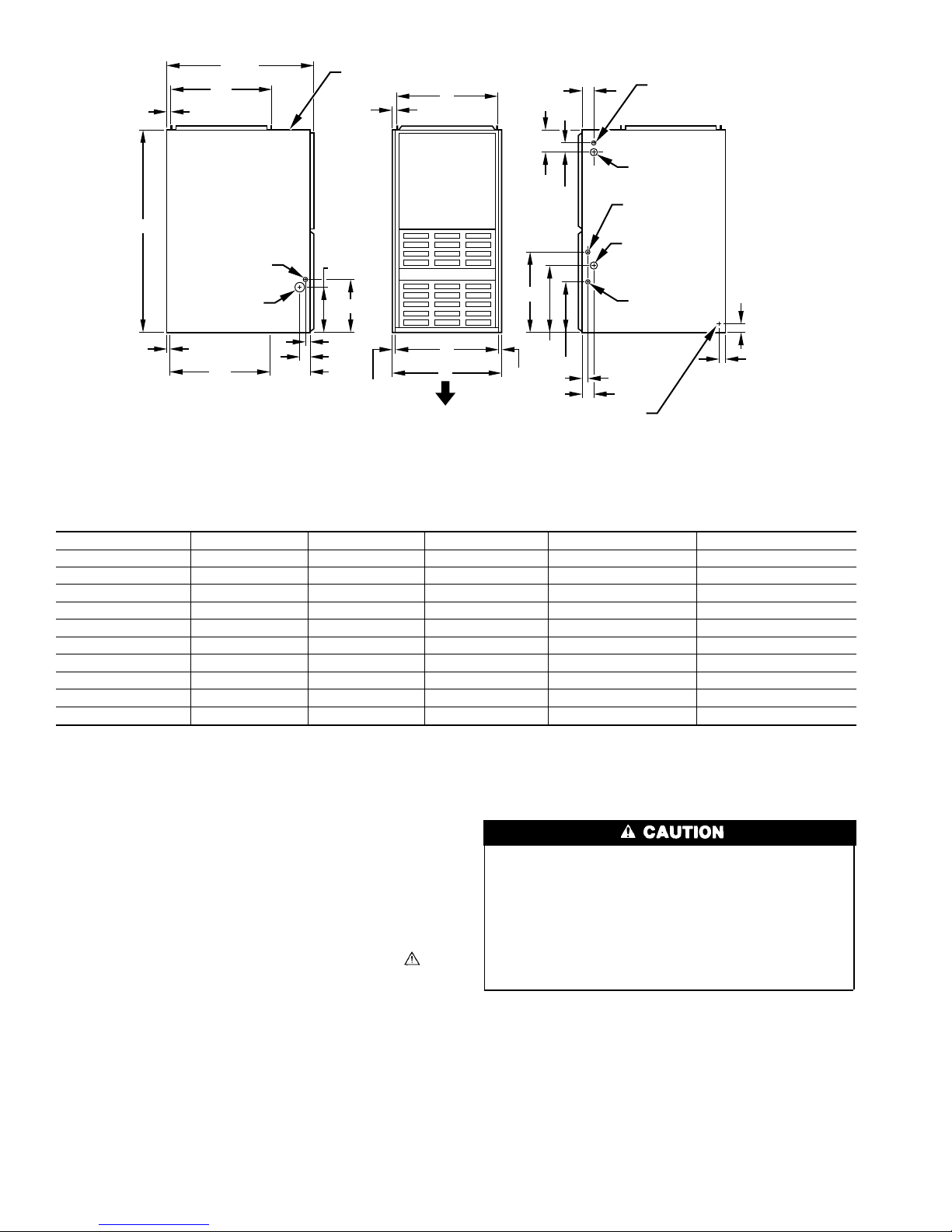
13
⁄16″
39 7⁄8″
20″
INLET
ACCESSORY
3
1
⁄4″ DIA HOLE
GAS ENTRY
28 1⁄2″
7
⁄8″ DIA
VENT CONNECTION
13
⁄16″
9 1⁄8″
10 1⁄4″
1
⁄2″ DIA
D
4 3⁄16″
2 15⁄16″
16 1⁄16″
2″
THERMOSTAT
WIRE ENTRY
7
⁄8″ DIA
ACCESSORY
7
⁄8″ DIA HOLE
POWER ENTRY
1 1⁄2″ DIA
R.H. GAS ENTRY
7
⁄8″ DIA
ACCESSORY
″ TYP
1
11
⁄16″
OUTLET
19″
ADDITIONAL 7⁄8″ DIA K.O. ARE
NOTE:
LOCATED IN THE TOP PLATE
AND BOTTOM PLATE
1 1⁄16″
2 1⁄8″
8 1⁄4″
11
⁄16″
Fig. 1—Dimensional Drawing
→
UNIT SIZE A D E VENT CONN SHIP. WT (LB)
050-08 14-3/16 12-9/16 12-11/16 4 124
050-12 14-3/16 12-9/16 12-11/16 4 127
070-08 14-3/16 12-9/16 12-11/16 4 141
070-12 14-3/16 12-9/16 12-11/16 4 145
096-12 17-1/2 15-7/8 16 4 154
096-16 17-1/2 15-7/8 16 4 154
115-16 17-1/2 15-7/8 16 4 171
115-20 21 19-3/8 19-1/2 4 181
115-22 21 19-3/8 19-1/2 4 181
135-20 24-1/2 22-7/8 23 5 192
heating equipment, observe precautions in the literature, on tags,
and on labels attached to or shipped with the unit and other safety
precautions that may apply.
Follow all safety codes. In the United States, follow all safety
→
codes including the National Fuel Gas Code (NFGC) NFPA No.
54-1996/ANSI Z223.1-1996 and the Installation Standards, Warm
Air Heating and Air Conditioning Systems (NFPA 90B)
ANSI/NFPA 90B. In Canada, refer to the current edition of the
National Standard of Canada CAN/CGA-B149.1- and .2-M95
Natural Gas and Propane Installation Codes (NSCNGPIC). Wear
safety glasses and work gloves. Have fire extinguisher available
during start-up and adjustment procedures and service calls.
Recognize safety information. This is the safety-alert symbol
When you see this symbol on the furnace and in instructions or
manuals, be alert to the potential for personal injury.
Understand the signal words DANGER, WARNING, and CAUTION. These words are used with the safety-alert symbol. DANGER identifies the most serious hazards which will result in severe
personal injury or death. WARNING signifies a hazard which
could result in personal injury or death. CAUTION is used to
identify unsafe practices which would result in minor personal
injury or product and property damage.
These instructions cover minimum requirements and conform to
existing national standards and safety codes. In some instances,
these instructions exceed certain local codes and ordinances,
Table 2—Dimensions (In.)
E
A
AIRFLOW
.
2
13 5 ⁄16″
10 1⁄4″
11
⁄16″
DIMPLES TO DRILL HOLES
FOR HANGER BOLTS (4 PLACES)
IN HORIZONTAL POSITION
1 1⁄16″
2 1⁄8″
5
⁄8″ TYP
A88324
especially those that may not have kept up with changing residential construction practices. We require these instructions as a
minimum for a safe installation.
ELECTROSTATIC DISCHARGE (ESD) PRECAUTIONS
PROCEDURE
Electrostatic discharge can affect electronic components.
Take precautions during furnace installation and servicing to
protect the furnace electronic control. Precautions will prevent electrostatic discharges from personnel and hand tools
which are held during the procedure. These precautions will
help to avoid exposing the control to electrostatic discharge
by putting the furnace, the control, and the person at the same
electrostatic potential.
1. Disconnect all power to the furnace. DO NOT TOUCH THE
CONTROL OR ANY WIRE CONNECTED TO THE CONTROL PRIOR TO DISCHARGING YOUR BODY’S ELECTROSTATIC CHARGE TO GROUND.
2. Firmly touch a clean, unpainted, metal surface of the furnace
chassis which is close to the control. Tools held in a person’s
hand during grounding will be satisfactorily discharged.
3. After touching the chassis you may proceed to service the
control or connecting wires as long as you do nothing that
recharges your body with static electricity (for example; DO
Page 3
NOT move or shuffle your feet, DO NOT touch ungrounded
objects, etc.).
4. If you touch ungrounded objects (recharge your body with
static electricity), firmly touch furnace again before touching
control or wires.
5. Use this procedure for installed and uninstalled (ungrounded)
furnaces.
6. Before removing a new control from its container, discharge
your body’s electrostatic charge to ground to protect the
control from damage. If the control is to be installed in a
furnace, follow items 1 through 5 before bringing the control
or yourself into contact with the furnace. Put all used AND
new controls into containers before touching ungrounded
objects.
7. An ESD service kit (available from commercial sources) may
also be used to prevent ESD damage.
→
The model 58ZAV Series 141 Furnaces are available in sizes
50,000 through 135,000 Btuh input capacities.
The design of the downflow/horizontal gas-fired furnace is
A.G.A./C.G.A. certified for natural and propane gases and for
installation on noncombustible flooring. The furnace is factoryshipped for use with natural gas. The manufacturer’s accessory gas
conversion kit is required to convert furnace for use with propane
gas.
These furnaces SHALL NOT be installed directly on carpeting,
tile, or any other combustible material other than wood flooring. In
downflow installations, the manufacturer’s accessory floor base
must be used when installed on combustible materials and wood
flooring. Special base is not required when this furnace is installed
on manufacturer’s Coil Assembly Part No. CD5 or CK5, or when
Coil Box Part No. KCAKC is used. This furnace is for installation
in alcoves, attics, crawlspaces, basements, closets, or utility rooms.
The design of this furnace line is not A.G.A./C.G.A. certified for
installation in mobile homes, recreation vehicles, or outdoors.
Before installing the furnace, refer to the current edition of the
NFGC and the NFPA 90B. Canadian installations must be installed
in accordance NSCNGPIC and all authorities having jurisdiction.
For a copy of the NFGC NFPA54/Z223.1, contact International
Approval Services U.S. Inc., 8501 E. Pleasant Valley Road,
Cleveland, OH 44131 or National Fire Protection Association Inc.,
Batterymarch Park, Quincy, MA 02269. For a copy of NFPA 90B,
contact National Fire Protection Association Inc., Batterymarch
Park, Quincy, MA 02269.
Before installing the furnace in Canada, refer to the current edition
of the NSCNGPIC. Contact Standards Department of Canadian
Gas Association, 55 Scarsdale Road, Don Mills, Ontario, Canada
M3B 2R3.
Application of this furnace should be indoors with special
attention given to vent sizing and material, gas input rate, air
temperature rise, and unit sizing. Improper installation or
misapplication of the furnace can require excessive servicing
or cause premature component failure.
Installation must conform to the regulations of the serving gas
supplier and the local building, heating, and plumbing codes in
effect in the area in which the installation is made, or in the
absence of local codes with the requirements of the NFGC.
This furnace is designed for a minimum continuous return-air
temperature of 60°F db or intermittent operation down to 55°F db
INTRODUCTION
such as when used with a night setback thermostat. Return-air
temperature must not exceed a maximum of 85°F db.
Improper installation, adjustment, alteration, service, maintenance, or use can cause carbon monoxide poisoning, explosion, fire, electrical shock, or other conditions which may
cause personal injury, loss of life, or property damage.
Consult a qualified installer, service agency, local gas supplier, or your distributor or branch for information or assistance. The qualified installer or agency must use only
factory-authorized and listed kits or accessories when modifying this product. Failure to follow this warning could result
in electrical shock, fire, personal injury, or death.
For accessory installation details, refer to the applicable installation literature.
NOTE: Remove all shipping brackets and materials before operating the furnace.
Step 1—Location
GENERAL
Do not install furnace in a corrosive or contaminated atmosphere. Make sure all combustion and circulating air requirements are followed, in addition to all local codes and
ordinances.
Do not use this furnace during construction when adhesives,
sealers, and/or new carpets are being installed. If the furnace
is required during construction, use clean outside air for
combustion and ventilation. Compounds of chlorine and
fluorine when burned with combustion air form acids which
cause corrosion of the heat exchangers and metal vent system.
Some of these compounds are found in paneling and dry wall
adhesives, paints, thinners, masonry cleaning materials, and
many other solvents commonly used in the construction
process.
Excessive exposure to contaminated combustion air will
result in safety and performance related problems.
This furnace must be installed so the electrical components are
protected from water.
Locate the furnace as close to the chimney/vent and as near the
center of the air distribution system as possible. The furnace
should be installed as level as possible.
When a furnace is installed so that the supply ducts carry air to
areas outside the space containing the furnace, the return air must
also be handled by a duct(s) sealed to the furnace casing and
terminating outside the space containing the furnace.
Provide ample space for servicing and cleaning. Always comply
with the minimum fire protection clearances shown on the unit
rating plate. This furnace shall not be installed directly on
carpeting, tile, or any combustible material other than wood
flooring. The furnace may be installed on combustible flooring
when installed with the accessory downflow subbase, which is
available from your distributor or branch when required.
LOCATION RELATIVE TO COOLING EQUIPMENT — The
cooling coil must be installed parallel with or on the downstream
side of the furnace to avoid condensation in the heat exchangers.
When installed parallel with a furnace, dampers or other means
used to control the flow of air must prevent chilled air from
entering the unit. If the dampers are manually operated, they must
be equipped with means to prevent operation of either unit unless
the damper is in the full-heat or full-cool position.
3
Page 4
HAZARDOUS LOCATIONS — When the furnace is installed in
a residential garage, it must be installed so that the burners and
ignition source are located at least 18 in. above the floor. The
furnace should be protected from physical damage by vehicles.
When a furnace is installed in public garages, airplane hangars, or
other buildings having hazardous atmospheres, the unit must be
installed in accordance with the recommended good practice
requirements of the National Fire Protection Association, Inc.
Step 2—Air For Combustion and Ventilation
Provisions for adequate combustion and ventilation air must be
provided in accordance with Section 5.3 of the NFGC, Air for
Combustion and Ventilation, or applicable provisions of the local
building codes.
Canadian installations must be installed in accordance with NSCNGPIC and all authorities having jurisdiction.
Air for combustion must not be contaminated by halogen
compounds, which include fluoride, chloride, bromide, and
iodide. These elements are found in aerosol sprays, detergents, bleaches, cleaning solvents, salts, air fresheners, and
other household products.
The operation of exhaust fans, kitchen ventilation fans,
clothes dryers, or fireplaces could create a NEGATIVE
PRESSURE CONDITION at the furnace. Make-up air MUST
be provided for the ventilation devices, in addition to that
required by the furnace.
All fuel-burning equipment must be supplied with air for combustion of the fuel. Sufficient air MUST be provided to ensure there
will not be a negative pressure in the equipment room or space. In
addition, a positive seal MUST be made between the furnace
cabinet and the return-air duct to avoid pulling air from the burner
area and draft safeguard opening.
The requirements for combustion and ventilation air depend upon
whether the furnace is located in an unconfined or confined space.
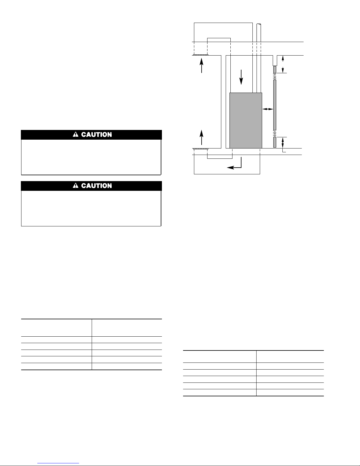
UNCONFINED SPACE — An unconfined space must have at
least 50 cu ft for each 1000 Btuh of input for all the appliances
(such as furnaces, clothes dryer, water heaters, etc.) in the space.
For Example:
58ZAV FURNACE
INPUT BTUH
46,000 307
69,000 460
92,000 613
115,000 767
135,000 920
MINIMUM SQ FT
WITH
7-1/2 FT CEILING
If the unconfined space is constructed unusually tight, air for
combustion and ventilation MUST come from either the outdoors
or spaces freely communicating with the outdoors. Combustion
and ventilation openings must be sized the same as for a confined
space. A minimum opening with a total of at least 1 sq in. per 5000
Btuh of total input rating for all equipment must be provided.
Return air must not be taken from the room unless an equal or
greater amount of air is supplied to the room.
CONFINED SPACE — A confined space has volume less than 50
cu ft per 1000 Btuh of the total input ratings of all appliances
VENT THROUGH ROOF
(CATEGORY I)
RETURN
AIR
INTERIOR
HEATED
SPACE
SUPPLY AIR
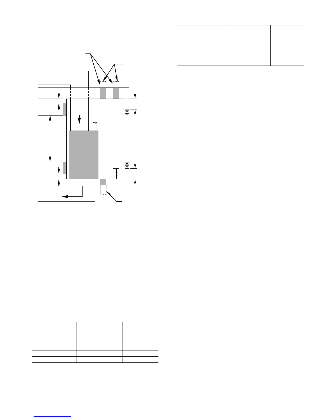
* Minimum opening size is 100 square in. with
minimum dimensions of 3-In.
†
Minimum of 3-In. when type B-1 vent is used.
12″ MAX
1 SQ IN.
PER 1000
BTUH* IN DOOR
OR WALL
UNCONFINED
SPACE
6″ MIN
(FRONT)
1 SQ IN.
PER 1000
BTUH* IN DOOR
OR WALL
12″ MAX
Fig. 2—Air for Combustion and Ventilation
(Inside Air)
installed in that space. A confined space MUST have 2 permanent
openings, 1 within 12 in. of the ceiling, and the other within 12 in.
of the floor. (See Fig. 2.)
NOTE: In determining the free area of an opening, the blocking
effect of the louvers, grilles, and screens must be considered. If the
free area of a louver or grille design is unknown, assume that wood
louvers have a 20 percent free area and metal louvers or grilles
have a 60 percent free area. Screens, when used, must not be
smaller than 1/4-in. mesh. Louvers and grilles must be constructed
so they cannot be closed.
The size of the openings depends upon whether the air comes from
inside or outside the structure.
1. All air from inside the structure:
a. Each opening MUST have at least 1 sq in. of free area per
1000 Btuh of the total input for all equipment within the
confined space, but not less than 100 sq in. per opening.
(See Fig. 2.)
For Example:
58ZAV FURNACE IN-
PUT BTUH
46,000 100
69,000 100
92,000 100
115,000 115
135,000 138
FREE AREA PER
OPENING (SQ IN.)
b. If the building is constructed unusually tight, in addition to
the 2 permanent openings that freely communicate with an
unconfined space, a permanent opening directly communicating with the outdoors should be provided. This opening
should have a minimum free area of 1 sq in. per 5000 Btuh
of total input rating for all equipment in the enclosure.
4
†
A93387
Page 5
c. If the furnace is installed on a raised platform to provide a
return-air plenum, and return air is taken directly from the
hallway or space adjacent to the furnace, all air for
combustion must come from outdoors. (See Fig. 3.)
DUCTS TO
OUTDOORS
1 SQ IN.
PER 4000
BTUH
*
12″ MAX
1 SQ IN.
PER 2000
BTUH
*
DUCTS
TO
OUTSIDE
1 SQ IN.
PER 2000
BTUH
*
12″ MAX
SUPPLY AIR
Minimum dimensions of 3-In.
*
Use any of the following
NOTE:
combinations of openings:
A & B C & D D & E F & G
RETURN
A
B
AIR
D
VENT
THROUGH
ROOF
(CATEGORY I)
CONFINED
E
C
DUCT
TO
OUTDOORS
F
SPACE
G
12″ MAX
12″
MAX
1 SQ IN.
PER 4000
BTUH
OUTDOORS
1 SQ IN.
PER 4000
BTUH
12″
MAX
1 SQ IN.
PER 4000
BTUH
*
*
Fig. 3—Air for Combustion and Ventilation
(Outside Air)
A93388
For Example:
58ZAV FURNACE IN-
PUT BTUH
46,000 23.0 6
69,000 34.3 7
92,000 46.0 8
115,000 57.6 9
135,000 69.0 10
FREE AREA PER
OPENING (SQ IN.)
ROUND PIPE
(IN. DIA)
c. When ducts are used, they must be of the same cross-
sectional area as the free area of the openings to which they
connect. The minimum dimension of rectangular ducts
must not be less than 3 in. (See Fig. 3.)
Step 3—Supply-Air Plenum Installation
(Downflow)
DOWNFLOW INSTALLATION
→
NOTE: This furnace is approved for use on combustible flooring
when manufacturer’s accessory floor base Part No.
KGASB0201ALL is used. Manufacturer’s accessory floor base is
not required when this furnace is installed on manufacturer’s Coil
Assembly Part No. CD5 or CK5, or Coil Box Part No. KCAKC is
used.
1. Determine application being installed from Table 3.
2. Construct hole in floor per dimensions specified in Table 3
and Fig. 4.
3. Construct plenum to dimensions specified in Table 3.
4. If downflow subbase (KGASB) is used, install as shown in
Fig. 5.
If coil assembly CD5, CK5, or Coil Box KCAKC is used,
install as shown in Fig. 6.
INSTALLATION ON A COMBUSTIBLE FLOOR
1. Cut and frame hole in floor per dimensions in Installation
Instructions packaged with downflow subbase.
2. When completed, downflow subbase, plenum, and furnace (or
coil casing when used) should be installed as shown in Fig. 6.
2. All air from outside the structure:
a. If combustion air is taken from outdoors through vertical
ducts, the openings and ducts MUST have at least 1 sq in.
of free area per 4000 Btuh of the total input for all
equipment within the confined space.
For Example:
58ZAV FURNACE
INPUT BTUH
46,000 11.5 4
69,000 17.3 5
92,000 23.0 6
115,000 28.8 7
135,000 34.5 7
FREE AREA PER
OPENING (SQ IN.)
b. If combustion air is taken from the outdoors through
horizontal ducts, the openings and ducts MUST have at
least 1 sq in. of free area per 2000 Btuh of the total input
for all equipment within the confined space.
ROUND PIPE
(IN. DIA)
5
Page 6
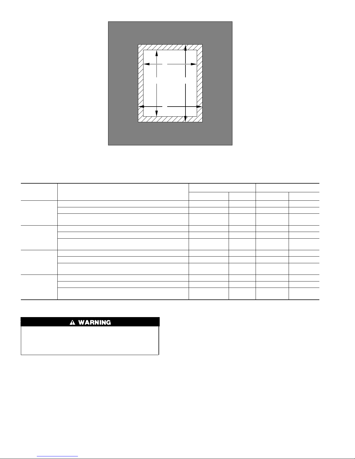
FURNACE
CASING
WIDTH
14-3/16
17-1/2
21
24-1/2
A
PLENUM
OPENING
B
OPENING
D
FLOOR
C
Fig. 4—Floor and Plenum Opening Dimensions
Table 3—Opening Dimensions (In.)
APPLICATION
Non-Combustible Flooring 12-11/16 19 13-3/8 19-5/8
Combustible Flooring Using KGASB Subbase 11-13/16 19 13-7/16 20-3/8
Combustible Flooring with CD5 or CK5 Coil Assembly or
KCAKC Coil Box
Non-Combustible Flooring 16 19 16-5/8 19-5/8
Combustible Flooring Using KGASB Subbase 15-1/8 19 16-3/4 20-3/8
Combustible Flooring with CD5 or CK5 Coil Assembly or
KCAKC Coil Box
Non-Combustible Flooring 19-1/2 19 20-1/8 19-5/8
Combustible Flooring Using KGASB Subbase 18-5/8 19 20-1/4 20-3/8
Combustible Flooring with CD5 or CK5 Coil Assembly or
KCAKC Coil Box
Non-Combustible Flooring 23 19 23-5/8 19-5/8
Combustible Flooring Using KGASB Subbase 22-1/8 19 23-3/4 20-3/8
Combustible Flooring with CD5 or CK5 Coil Assembly or
KCAKC Coil Box
PLENUM OPENING FLOOR OPENING
ABCD
12-5/16 19 13-5/16 20
15-1/2 19 16-1/2 20
19 19 20 20
22-1/2 19 23-1/2 20
A96283
Step 4—Horizontal Attic Installation
Do not install the furnace on its back; safety control operation
will be adversely affected. Never connect return-air ducts to
the sides or back of the furnace. Failure to follow this warning
could result in fire, personal injury, or death.
The furnace can be installed horizontally on either the left-hand
(LH) or right-hand (RH) side. A typical attic installation is shown
in Fig. 7.
CONSTRUCT A WORKING PLATFORM
Construct working platform on location where all required furnace
clearances are met. (See Table 1 and Fig. 7.)
INSTALL FURNACE
1. Position furnace in desired location.
2. Connect gas supply pipe. See Fig. 7 for typical piping entry.
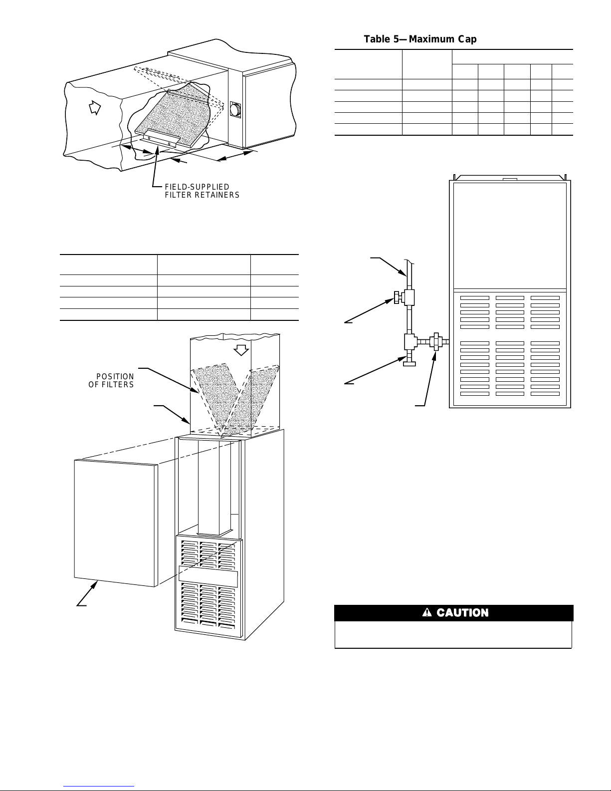
3. Install field-supplied filter retainers as indicated in Fig. 10 and
Table 4 before connecting return-air duct to furnace.
4. Connect supply- and return-air ducts.
5. Install 24- X 24-in. sheet metal shield on platform in front of
louvered control panel as shown in Fig. 7.
→
Step 5—Horizontal Crawlspace Installation
The furnace can be installed horizontally with either the LH or RH
side up. In a crawlspace, furnace can either be hung from floor
joist (see Fig. 9) or installed on suitable blocks or pad. (See Fig. 8.)
The furnace can be suspended from each corner by hanger bolts (4
each 3/8-in. all-thread rod) cut to desired length, 1- X 3/8-in. flat
washer, 3/8-in. lockwasher, and 3/8-in. nut. Dimples are provided
for hole locations. (See Fig. 1.)
Since horizontal crawlspace installation is very similar to attic
installation, refer to Step 4. The installation of a sheet metal shield
in front of louvered control panel is covered in Step 4. For a
crawlspace installation, this same sheet metal shield must be
installed above louvered control panel. Extend sheet metal shield
over furnace top far enough to cover gas pipe entry hole.
6
Page 7
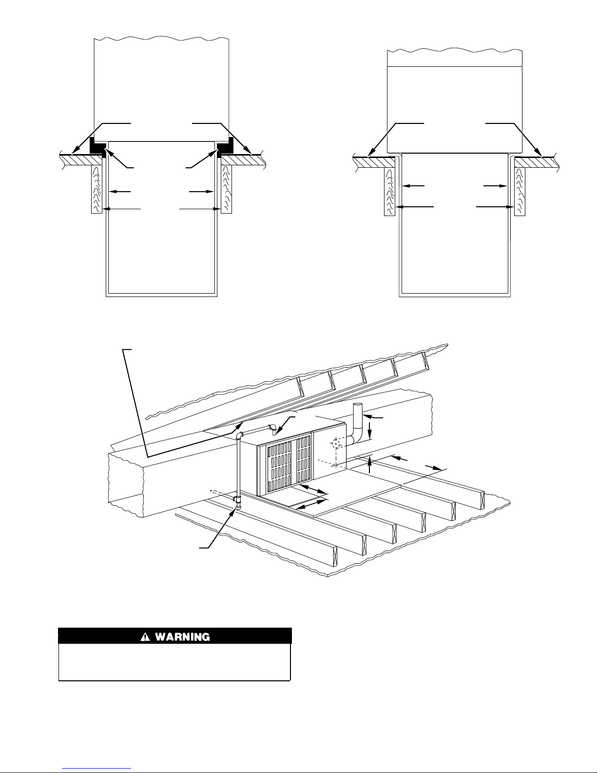
FURNACE
(OR COIL CASING
WHEN USED)
FURNACE
CD5 OR CK5
COIL ASSEMBLY
OR KCAKC
COIL BOX
COMBUSTIBLE
FLOORING
DOWNFLOW
SUBBASE
SHEET METAL
PLENUM
FLOOR
OPENING
A96285
Fig. 5—Furnace, Plenum, and Subbase Installed on a
Combustible Floor
LINE CONTACT ONLY PERMISSIBLE BETWEEN
LINES FORMED BY INTERSECTIONS OF
THE TOP AND TWO SIDES OF THE FURNACE
JACKET AND BUILDING JOISTS,
STUDS, OR FRAMING.
COMBUSTIBLE
FLOORING
SHEET METAL
PLENUM
FLOOR
OPENING
A96284
Fig. 6—Furnace, Plenum, and Coil Assembly or Coil
Box Installed on a Combustible Floor
SHEET
METAL
SEDIMENT TRAP
Fig. 7—Typical Attic Installation
Step 6—Filter Arrangement
Never operate unit without a filter or with filter access door
removed. Failure to follow this warning could result in fire,
personal injury, or death.
The 2 factory-supplied filters are shipped in the blower compartment. After return-air duct has been connected to furnace, install
filters in a V-formation inside return-air plenum. See Fig. 10 and
Table 4 for horizontal applications. Horizontal filter retainers must
be field supplied. See Fig. 11 for downflow applications.
GAS
ENTRY
24
FLUE VENT
MIN
″
24
6
″
″
30-IN. MIN
WORK AREA
Step 7—Gas Piping
Gas piping must be installed in accordance with national and local
codes. Refer to the current edition of the NFGC.
Canadian installations must be installed in accordance with NSCNGPIC and all authorities having jurisdiction.
Refer to Table 5 for recommended gas pipe sizing. Risers should
be used to connect to the furnace and to the meter.
A82178
7
Page 8
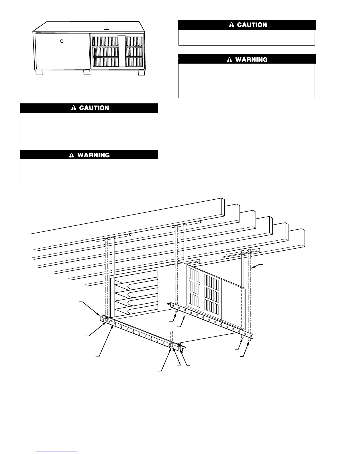
A95235
Fig. 8—Horizontal Installation on Blocks
If a flexible connector is required or allowed by the authority
having jurisdiction, black iron pipe shall be installed at the
gas valve and extend a minimum of 2 in. outside the furnace
casing.
Use the proper length of pipes to avoid stress on the gas
control manifold. Failure to follow this warning could result
in a gas leak, causing fire, explosion, personal injury, or
death.
Connect the gas pipe to the furnace using a backup wrench to
avoid damaging gas controls.
Never purge a line into a combustion chamber. Never use
matches, candles, flame, or other sources of ignition to check
for gas leakage. Use a soap-and-water solution to check for
gas leaks. Failure to follow this warning could result in fire,
explosion, personal injury, or death.
Joint compounds (pipe dope) should be applied sparingly and only
to the male threads of the joints. This pipe dope must be resistant
to the action of propane gas.
An accessible manual shutoff valve MUST be installed upstream
of the furnace gas controls and within 72 in. of the furnace. A
1/8-in. NPT plugged tapping, accessible for test gage connection,
MUST be installed immediately upstream of the gas supply
connection to the furnace and downstream of the manual shutoff
valve. Place a ground joint union between the gas control manifold
and the manual shutoff.
Install a sediment trap in the riser leading to the furnace. The trap
can be installed by connecting a tee to the riser leading from the
ANGLE
IRON OR
EQUIVALENT
(B)
(A)
ROD LOCATION
USING DIMPLE
LOCATORS
(SEE DIMENSIONAL
DWG FOR
LOCATIONS)
(A) PREFERRED ROD LOCATION
(B) ALTERNATE ROD LOCATION
Fig. 9—Horizontal Crawlspace Installation on Hanger Rods
3
/8-IN. HEX NUT
& WASHER (4)
REQD PER ROD
(B)
3
⁄8-IN. ROD
(A)
(A)
(B)
(A)
(B)
NOTES:
1. A 1 In. clearance minimum between top of
furnace and combustible material.
2. The entire length of furnace must be
supported when furnace is used in horizontal
position.
A96633
8
Page 9
AIRFLOW
12″
4″
FIELD-SUPPLIED
FILTER RETAINERS
Fig. 10—Horizontal Filter Arrangement
Table 4—Filter Retainer (In.)
FURNACE CASING
WIDTH
14-3/16 (2) 14 X 20 X 1 14-3/8
17-1/2 (2) 14 X 20 X 1 13-3/8
21 (2) 16 X 20 X 1 11-5/8
24-1/2 (2) 16 X 20 X 1 10-1/4
FILTER SIZE AND
QUANTITY
AIRFLOW
Table 5—Maximum Capacity of Pipe *
NOMINAL IRON
PIPE SIZE
(IN.)
1/2 0.622 175 120 97 82 73
3/4 0.824 360 250 200 170 151
1 1.049 680 465 375 320 285
1-1/4 1.380 1400 950 770 660 580
1-1/2 1.610 2100 1460 1180 990 900
* Cubic ft of gas per hr for gas pressures of 0.5 psig (14-in. wc) or less, and a
pressure drop of 0.5-in. wc (based on a 0.60 specific gravity gas). Ref: Table
D
A82173
D
10-2 NFPA 54/ANSI Z223.1-1996.
GAS
SUPPLY
MANUAL
SHUTOFF
VALVE
(REQUIRED)
INTERNAL
DIAMETER
(IN.)
LENGTH OF PIPE (FT)
10 20 30 40 50
INSTALLATION
POSITION
OF FILTERS
RETURN-AIR
PLENUM
ACCESS DOOR
A88486
Fig. 11—Downflow Filter Arrangement
furnace. Connect a capped nipple into the lower end of the tee. The
capped nipple should extend below the level of the gas controls.
(See Fig. 12.)
Piping should be pressure tested in accordance with local and
national plumbing and gas codes before the furnace has been
attached. If the pressure exceeds 0.5 psig (14-in. wc), the gas
SEDIMENT
TRAP
UNION
A89414
Fig. 12—Typical Gas Pipe Arrangement
supply pipe must be disconnected from the furnace and capped
before the pressure test. If the test pressure is equal to or less than
0.5 psig (14-in. wc), turn off electric shutoff switch located on the
gas valve before the test. It is recommended that the ground joint
union be loosened before pressure testing.
After all connections have been made, purge the lines and check
for gas leakage with regulated gas supply pressure.
Step 8—Electrical Connections
115-V WIRING
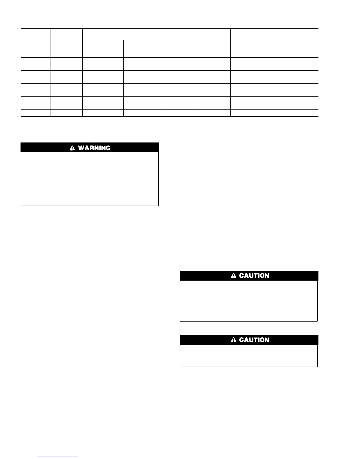
Refer to the unit rating plate or Table 6 for equipment electrical
requirements. The control system requires an earth ground for
proper operation.
Do not connect aluminum wire between disconnect switch
and furnace. Use only copper wire.
Make all electrical connections in accordance with the current
edition of the National Electrical Code (NEC) ANSI/NFPA
70-1996, and any local codes or ordinances that might apply. For
Canadian installations, all electrical connections must be made in
accordance with Canadian Electrical Code CSA C22.1, or authorities having jurisdiction.
NOTE: Proper polarity must be maintained for 115-v wiring. If
polarity is incorrect, control board fault code indicator light will
flash rapidly and furnace will not operate.
9
Page 10
→
UNIT SIZE
050-08 115—60—1 127 104 6.6 14 42 15
050-12 115—60—1 127 104 8.1 14 34 15
070-08 115—60—1 127 104 6.7 14 42 15
070-12 115—60—1 127 104 8.4 14 33 15
096-12 115—60—1 127 104 9.2 14 30 15
096-16 115—60—1 127 104 10.2 14 28 15
115-16 115—60—1 127 104 10.1 14 28 15
115-20 115—60—1 127 104 13.3 12 33 20
115-22 115—60—1 127 104 15.2 12 29 20
135-20 115—60—1 127 104 14.3 12 31 20
* Permissible limits of the voltage range at which the unit will operate satisfactorily.
† Time-delay fuse is recommended.
‡ Length shown is as measured 1 way along wire path between unit and service panel for maximum 2 percent voltage drop.
VOLTS—
HERTZ—
PHASE
OPERATING VOLTAGE RANGE
Maximum* Minimum*
Table 6—Electrical Data
MAXIMUM
UNIT AMPS
MINIMUM
WIRE GAGE
MAXIMUM WIRE
LENGTH FT‡
maintain a minimum of 1/4-in. upward slope per linear ft and it
shall be rigidly supported every 5 ft or less with hangers or straps
The cabinet MUST have an uninterrupted or unbroken ground
according to NEC ANSI/NFPA 70-1996 and Canadian Electrical Code CSA C22.1 or local codes to minimize personal
injury if an electrical fault should occur. This may consist of
electrical wire or conduit approved for electrical ground when
installed in accordance with existing electrical codes. Do not
use gas piping as an electrical ground. Failure to follow this
warning could result in electrical shock, fire, or death.
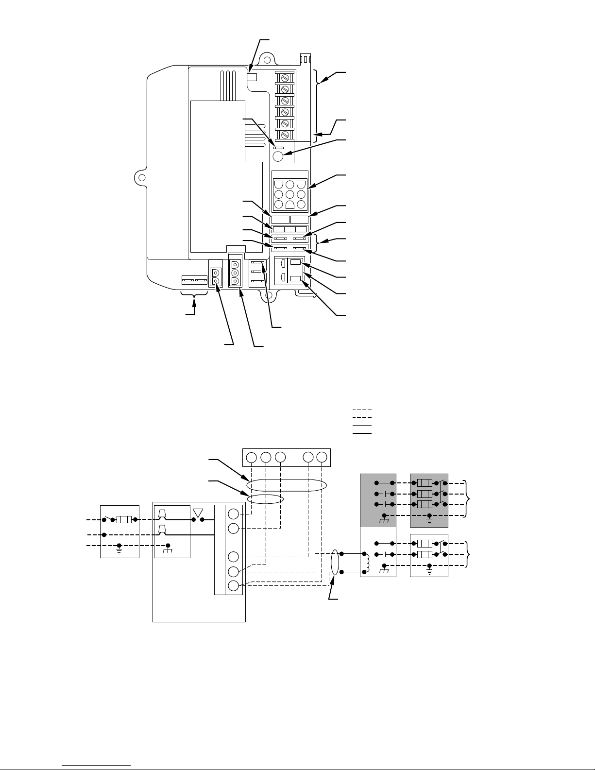
24-V WIRING — Make field 24-v connections at the 24-v terminal strip. (See Fig. 13.) Connect terminal Y as shown in Fig. 14 for
proper operation in cooling mode. Use AWG No. 18 color-coded
wire only.
The 24-v circuit contains an automotive-type, 3-amp fuse located
on the main control board. Any direct shorts during installation,
service, or maintenance could cause this fuse to blow. If fuse
replacement is required, use ONLY a 3-amp fuse of identical size.
to ensure that there will be no movement after installation.
Step 10—Start-up, Adjustment, and Safety Check
GENERAL
NOTE: Proper polarity must be maintained for 115-v wiring. If
polarity is incorrect, control board fault indicator light will flash
rapidly and furnace will not operate.
The furnace must have a 115-v power supply properly connected
and grounded. Proper polarity must be maintained for correct
operation. Thermostat wire connections at R, W, C, and Y must be
made at the 24-v terminal block on the control board. The gas
service pressure must not exceed 0.5 psig (14-in. wc), but must be
no less than 0.16 psig (4.5-in. wc).
Before operating the furnace, check each manual reset switch for
continuity. If necessary, press the button to reset the switch.
The blower compartment door must be in place to complete the
115-v circuit to the furnace.
ACCESSORIES
1. Electronic Air Cleaner (EAC)
Two spring clamp terminals (for 12 gage maximum, solid or
stranded wire), marked EAC-1 and EAC-2, are provided for
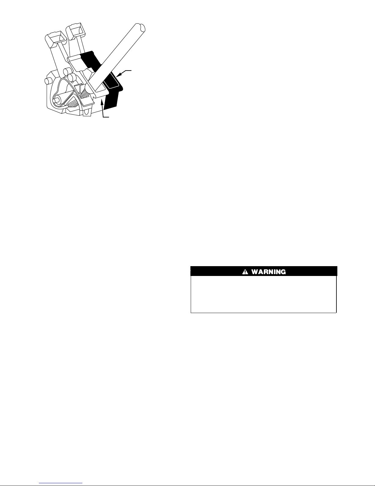
EAC connection. (See Fig. 13.) These terminals are energized
with 115v (1.5-amp maximum) during blower motor operation. To connect EAC power leads to furnace control board,
strip approximately 1/8 in. of insulation from wire. Open
terminal by depressing switch arm with a screwdriver or
finger, and insert wire as shown in Fig. 15.
This furnace is equipped with 2 manual reset limit switches in
the gas control area. The switches will open and shut off
power to the gas valve if a flame rollout or an overheating
condition occurs in the gas control area. DO NOT bypass the
switches. Correct inadequate combustion air supply problem
and reset the switches.
SEQUENCE OF OPERATION
2. Humidifier (HUM)
Screw terminals (HUM and Com) are provided for 24-v
humidifier connection. The terminals are energized with 24v
(0.5-amp maximum) after inducer motor prepurge period.
NOTE: A field-supplied, 115-v controlled relay connected to
EAC terminals may be added if humidifier operation is desired
during blower operation.
Step 9—Venting
Refer to the National or Local Installation Code such as; National
Fuel Gas Code NFPA No. 54-1996/Z223.1-1996, or the Canadian
Installation Code, CAN B149.1- and .2-M95, for proper vent
sizing and installation requirements. Use the enclosed Venting
Tables for Category I Fan-Assisted Furnaces for a quick, easy
reference. The horizontal portion of the venting system shall
Furnace control must be grounded for proper operation or
control will lockout. Control is grounded through green wire
routed to gas valve and burner bracket screw.
Using the schematic diagram shown in Fig. 16, follow the
sequence of operation through the different modes. Read and
follow the wiring diagram very carefully.
NOTE: If there is a power interruption and any thermostat call,
the control will initiate a 90-sec blower only on period before
starting another cycle.
1. Heating mode
When the thermostat "calls for heat," R-W circuit closes. The
furnace control performs a self-check, verifies the pressure
switch contacts are open, and starts the inducer motor.
10
MAXIMUM
FUSE OR HACR-
TYPE CKT BKR
AMPS†
Page 11
BLOWER OFF DELAY
ADJUSTMENT SWITCH
115-VAC (L1)
POWER
SUPPLY
HOT SURFACE
CONNECTOR
TEST/TWIN
SEC-1
3-AMP FUSE
COOL
HEAT
IGNITOR
G
R
Y
W
Com
24V
HUM
24V THERMOSTAT
TERMINALS
HUMIDIFIER TERMINAL
(24-VAC 0.5 AMP MAX)
LED OPERATION &
STATUS LIGHT
HARNESS CONNECTOR
24V TRANSFORMER SEC-2
SPARE 1
BLOWER SPEED
SELECTION TERMINALS
SPARE 2
EAC 1 (BLACK)
EAC-ELECTRONIC AIR CLEANER
TERMINALS (115-VAC 1.5 AMP MAX)
EAC 2 (WHITE)
115-VAC (L2) NEUTRAL
CONNECTION
INDUCER MOTOR
CONNECTOR
Fig. 13—Control Board
A93052
FIVE
WIRE
THREE-WIRE
HEATING-
ONLY
BLK
WHT
115-VOLT FUSED
DISCONNECT
SWITCH
(WHEN
GND
BLK
WHT
GND
AUXILIARY
J-BOX
CONTROL
BOX
REQUIRED)
FURNACE
Fig. 14—Heating and Cooling Application Wiring Diagram
a. Prepurge period—As the inducer motor comes up to speed,
the pressure switch contacts close to begin a 15-sec
prepurge period.
b. Ignitor warm-up—At the end of the prepurge period, the
ignitor is energized for a 17-sec ignitor warm-up period.
NOTE 2
W
R
G
C
Y
24-VOLT
TERMINAL
BLOCK
FIELD 24-VOLT WIRING
FIELD 115-, 208/230-, 460-VOLT WIRING
FACTORY 24-VOLT WIRING
FACTORY 115-VOLT WIRING
WCR GY
NOTE 1
THERMOSTAT
TERMINALS
CONDENSING
FIELD-SUPPLIED
FUSED DISCONNECT
GND
UNIT
TWO
WIRE
NOTES: Connect Y-terminal as shown for proper operation.
1.
2.
Some thermostats require a "C" terminal connection as shown.
3.
If any of the original wire, as supplied, must be replaced, use
same type or equivalent wire.
c. Ignition sequence—When the ignitor warm-up period is
completed, the gas valve opens, permitting gas flow to the
burners where it is ignited. After 5 sec, the ignitor is
de-energized and a 2-sec flame-sensing period begins.
11
208/230- OR
460-VOLT
THREE
PHASE
208/230-
VOLT
SINGLE
PHASE
A96415
Page 12
EAC1
EAC2
A93053
Fig. 15—EAC Terminals on Control Board
d. HUM terminal is energized with the gas valve. See
Accessories in Electrical Connections section.
e. Flame-sensing—When burner flame is sensed, the control
begins the blower on delay period and continues holding
the gas valve open. If burner flame is not sensed, the
control closes the gas valve and repeats the ignition cycle.
NOTE: Ignition sequence will repeat 3 additional times before a
lockout occurs. Lockout automatically resets after 3 hr, or can be
manually reset by turning 115v off (not at thermostat) for 3 sec
minimum, then on again.
f. Blower on delay—Forty sec after burner flame is proven,
the blower motor is energized on heating speed. Simultaneously, terminals HUM and C
EAC-1 and EAC-2 for EAC are energized. If jumper is on
pin 6 and pin 9, the blower on delay period is 60 sec.
g. Blower off delay—When the thermostat is satisfied, the
circuit between R and W is broken, de-energizing the gas
valve and stopping gas flow to the burners. The blower
motor, and EAC remain energized 90, 135, 180, or 225 sec
(depending on the blower off time selection). The furnace
is factory set for a 135-sec blower off delay period.
h. Post-purge—The inducer motor remains energized 5 sec
after the burners are extinguished. If jumper is on pin 6 and
pin 9, the post-purge period is 15 sec.
2. Cooling mode
When the thermostat "calls for cooling," R-G and R-Y circuits
close. The R-Y circuit starts the outdoor condensing unit and
combined R-Y and R-G circuits start the furnace blower motor
on cooling speed. The EAC-1 terminal is energized with 115v
whenever the blower is operating on cooling speed.
When the thermostat is satisfied, R-G and R-Y circuits are
broken. Furnace blower and EAC continue operating on
cooling speed for an additional 90 sec.
3. Continuous blower mode
NOTE: EAC-1 terminal is energized with 115v whenever blower
is operating.
When the R-G circuit is made, the blower motor operates on
heating speed. During a call for heat, the blower stops,
allowing the furnace heat exchangers to heat up more quickly,
then restarts at the end of the 40-sec blower on delay period.
If jumper is on pin 6 and pin 9, the blower on delay period is
60 sec.
The blower reverts to continuous operation after the heating
cycle is completed.
OM for humidifier, and
When the thermostat "calls for cooling," the blower operates
on cooling speed. When the thermostat is satisfied, the blower
operates an additional 90 sec before reverting back to continuous operation on heating speed.
4. Heat pump mode
When installed with a heat pump, the furnace control auto-
matically changes the timing sequence to avoid long blower
off time during demand defrost cycles. When the W-Y or
W-Y-G thermostat inputs are received at the same time, the
control changes the blower to heating speed or starts the
blower if it was off, and begins a heating cycle. The blower
remains on until the end of the prepurge period, then shuts off
until the end of the ignition warm up and trial for ignition
periods (a total of 24 sec). The blower then comes back on at
heating speed.
When the W input signal disappears, the control begins the
normal inducer post-purge period and the blower changes to
cooling speed after a 1-sec delay. If the W-Y-G signals
disappear at the same time, the blower remains on for the
selected heating blower off delay period and the inducer goes
through its normal post-purge period. If the W-Y inputs
should disappear, leaving the G signal input, the control goes
into continuous blower and the inducer remains on for the
normal post-purge period.
Anytime the control senses false flame, the control locks out
of the heating mode. This occurs because the control cannot
sense the W input due to the false flame signal and, as a result,
sees only the Y input and goes into cooling mode blower off
delay. All other control functions remain in standard format.
NOTE: EAC-1 terminal is energized whenever blower operates.
HUM terminal is only energized when gas valve is energized.
START-UP PROCEDURES
1. Purge gas lines—After all connections have been made, purge
the lines and check for leaks.
Never purge a line into a combustion chamber. Never use
matches, candles, flame, or other sources of ignition to check
for gas leakage. Use a soap-and-water solution to check for
gas leaks. Failure to follow this warning could result in fire,
explosion, personal injury, or death.
2. Component test—The furnace control board allows all components, except gas valve, to be run for a short period of time.
This feature helps diagnose a system problem in case of a
component failure. To initiate component test procedure, short
(jumper) the TEST 1/4-in. quick connect terminal on control
board (adjacent to diagnostic light) and the C
OM terminal on
thermostat connection block for approximately 2 sec. (See Fig.
13.)
NOTE: Component test feature will not operate if any thermostat
signal is present at control board.
Component test sequence is as follows.
a. Momentarily jumper TEST and C
OM terminals until LED
goes off.
b. LED will display previous fault 4 times.
c. Inducer motor starts and continues to run for entire com-
ponent test.
d. Hot surface ignitor is energized for 15 sec, then de-
energized.
e. Blower motor operates on cooling speed for 10 sec, then
stops.
12
Page 13
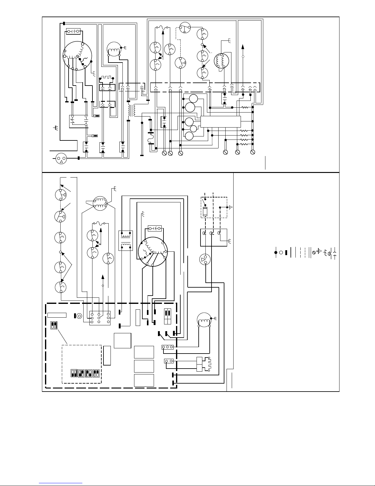
L2
CAP
BLWM
START
OL
LO
SCHEMATIC DIAGRAM
(NATURAL GAS & PROPANE)
NOTE #4
TO 115VAC FIELD DISCONNECT
NEUTRAL
L1
HI
MED LO
MED HI
COM
NOTE #8
HEAT
SPARE-2
EQUIPMENT GROUND
ILK
YEL
COM
COOL
SPARE-1
HI/LO
EAC-1
BLWR
L1
IDM
HSI
2
1
PL52
1
PL2
EAC-2
HSIR
IDR
NOT USED
PL3
2
1
3
PR2
24VAC
115VAC
TRAN
PR1
NOTE #6
FU1
TEST/TWIN
FL
PRS
NOTE #13
LS
(WHEN USED)
LGPS
(WHEN USED)
NOTE #11
FRS1 FRS2
(WHEN USED)
7
SEC-2
SEC-1
GVR-2
HUM
NOTE #12
PL1
NOTE #13
1
4
HI/LO
BLWR
HSIR
W
R
NOTE #14
GVR
IDR
ALS
NOTE #5
NOTE #11
(WHEN USED)
GV
BVSS
NOTE #14
DSS
3-P
2
3
GVR-1
CPU
2-C
FSE
322869-101 REV. D
1-M
NOT USED
8
Y
NOT USED
9
6
5
OM
G
C
NOTES:
optimum speed selection.
1. If any of the original equipment wire is replaced use wire rated for 105°C.
2. Inducer (IDM) and blower (BLWM) motors contain internal auto-reset thermal overload switches (OL).
3. Blower motor speed selections are for average conditions, see installation instructions for details on
4. Use only copper wire between the disconnect switch and the furnace junction box (JB).
5. This wire must be connected to furnace sheetmetal for control to detect flame.
(135 seconds only on some models)
after three hours.
models only.
6. Replace only with a 3 amp fuse.
7. Yellow lead not on all motors.
8. Blower-on delay, gas heating 45 seconds, cooling or heat pump 2 seconds.
9. Blower-off delay, gas heating 90, 135, 180 or 225 seconds, cooling or heat pump 90 seconds.
10. I gnition-lockout will occur after four consecutive unsuccessful trials-for-ignition. Control will auto-reset
11. When used, auxiliary limit switch (ALS) is on some downflow models only. When used, FL is on upflow
installed.
12. Some models may have spade quick connect terminals.
13. Factory connected when LGPS is not used.
14. Factory connected when BVSS is not used. BVSS used when Chimney Adapter Accessory Kit is
A96262
(WHEN USED)
(WHEN USED)
(WHEN USED)
NOTE #11
NOTE #14
GRY
SW2
BLOWER
PRS
ALS
BVSS
DSS
LGPS
ORN
ORN
ORN
ORN
ORN
W
SW1
OFF
DELAY
NOTE #9
(NOT ON ALL MODELS)
PCB
GV
BLU
LED
TEST/TWIN
90 SEC
135 SEC
3-P
FRS1 FRS2
RED
180 SEC
1-M
LS
WHT
1
2
3
PL1
225 SEC
NOTE #13
NOTE #14
OM
C
HUM
SELECTION CHART
BLOWER OFF DELAY
NOTE #5
2-C
GRN
FL
BLK
NOTE #11
(WHEN USED)
BLU
FSE
RED
4
SEC-2
87
5
9
6
SEC-1
HI/LO
GVR
GRN
BLK (HI)
FUSE
FU1
BRN
SPARE-1
COOL
SPEED
BLOWER
HSIR IDR BLWR
CAP
BRN
BLWM
START
OL
WHT
RED (LO)
NOTE #8
YEL (MED HI)
BLU (MED LO)
WHT (COM)
1.5 AMP
SPARE-2
EAC-1
EAC-2
HEAT
OM
L2
PR2
C
SELECT
123
PL3
PL2
VAC
120
WHT
2
1
PR1
L1
WHT (COM)
WHT
TRAN
RED
24 VAC-3A
RELAY
L1
NEUTRAL
NOTE #4
FU2
FUSED DISCONNECT
SWITCH (WHEN REQ’D)
JB
BLK
ILK
GRN
WHT
BLK
JUNCTION
UNMARKED TERMINAL
PCB TERMINAL
FACTORY WIRING (115VAC)
FACTORY WIRING (24VAC)
FIELD WIRING (115VAC)
FIELD WIRING (24VAC)
CONDUCTOR ON PCB
FIELD WIRING TERMINAL
FIELD GROUND
EQUIPMENT GROUND
FIELD SPLICE
GRN
PCB PRINTED CIRCUIT BOARD
PL1 9-CIRCUIT CONNECTOR
PL2 2-CIRCUIT PCB CONNECTOR
PL3 3-CIRCUIT IDM CONNECTOR
PL5 2-CIRCUIT HSI/PCB CONNECTOR
PRS PRESSURE SWITCH, SPST-(N.O.)
TEST/TWIN COMPONENT TEST & TWIN TERMINAL
TRAN TRANSFORMER-115VAC/24VAC
PLUG RECEPTACLE
Fig. 16—Unit Wiring Diagram
IDM
BLK
WHT
PL5
WHT
BLK
BLK
BLK
12
HSI
(FIELD INSTALLED & SUPPLIED)
ALS AUXILIARY LIMIT SWITCH, OVERTEMP. -MANUAL RESET, SPST-(N.C.)
BLWR BLOWER MOTOR RELAY, SPST-(N.O.)
BLWM BLOWER MOTOR
BVSS BL OCKED VENT SHUTOFF SWITCH, SPST - (N.C.)
CAP CAPACITOR
CPU MICROPROCESSOR AND CIRCUITRY
DSS DRAFT SAFEGUARD SWITCH
EAC-1 ELECTRONIC AIR CLEANER CONNECTION (115 VAC 1.5 AMP MAX.)
EAC-2 ELE CTRONIC AIR CLEANER CONNECTION (COMMON)
FL FUSIBLE LINK
FRS FLAME ROLLOUT SW. -MANUAL RESET, SPST-(N.C.)
FSE FLAME PROVING ELE C TRODE
FU1 FUSE, 3 AMP, AUTOMOTIVE BLADE TYPE, FACTORY INSTALLED
FU2 FUSE OR CIRCUIT BREAKE R CU RR ENT INTERRUPT DEVICE
GV GAS VALVE-REDUNDANT OPERATORS
GVR GAS VALVE RELAY, DPST-(N.O.)
HI/LO BLOWER MOTOR SPEED CHANGE RELAY, SPDT
HSI HOT SURFACE IGN ITOR (115 VAC)
HSIR HOT SURFACE IGN I TOR RELAY, SPST-(N.O.)
HUM 24VAC HUMIDIFIER CONNECTION (.5 AMP. MAX.)
IDM INDUCED DRAFT MOTOR
IDR INDUCED DRAFT RELAY, SPST-(N.O.)
ILK BLOWER ACCESS PANEL INTERLOCK SW I TCH, SPST-(N.O.)
JB JUNCTION BOX
LED LIGHT-EMITTING DIODE FOR STATUS CODES
LGPS LOW GAS PRESSURE SWITCH, SPST-(N.O.)
LS LIMIT SWITCH, AUTO RESET, SPST(N.C.)
LEGEND
OL AUTO-RESET INTERNAL MOTOR OVERLOAD TEMP. SW.
13
Page 14
f. Blower motor operates on heating speed for 10 sec, then
stops.
g. Inducer motor stops.
3. To operate furnace, follow procedures on operating instruction
label attached to furnace.
4. With furnace operating, set thermostat below room temperature and observe that furnace goes off. Set thermostat above
room temperature and observe that furnace restarts.
ADJUSTMENTS
1. Set gas input rate
Furnace gas input rate on rating plate is for installations at
altitudes up to 2000 ft. Furnace input rate must be within ±2
percent of input on furnace rating plate.
a. Determine natural gas orifice size and manifold pressure
for correct input.
(1.) Obtain average yearly heat value (at installed altitude)
from local gas supplier.
(2.) Obtain average yearly specific gravity from local gas
supplier.
(3.) Verify furnace model. Table 7 can only be used for
model 58ZAV Furnaces.
(4.) Find installation altitude in Table 7.
NOTE: For Canada altitudes of 2000 to 4500 ft, use U.S.A.
altitudes of 2001 to 3000 ft in Table 7.
(5.) Find closest natural gas heat value and specific gravity
in Table 7.
(6.) Follow heat value and specific gravity lines to point of
intersection to find orifice size and manifold pressure
settings for proper operation .
EXAMPLE: (0—2000 ft altitude)
Heating value = 1050 Btu/cu ft
Specific gravity = 0.62
Therefore: Orifice No. 43*
Manifold pressure 3.6-in. wc
* Furnace is shipped with No. 43 orifices. In this example
all main burner orifices are the correct size and do not need
to be changed to obtain proper input rate.
(7.) Check and verify burner orifice size in furnace.
NEVER ASSUME ORIFICE SIZE. ALWAYS
CHECK AND VERIFY.
b. Adjust manifold pressure to obtain input rate.
(1.) Remove regulator adjustment seal cap. (See Fig. 17.)
(2.) Turn adjusting screw, counterclockwise (out) to de-
crease manifold pressure or clockwise (in) to increase
manifold pressure.
NOTE: This furnace has been approved for a manifold pressure
of 3.2-in. wc to 3.8-in. wc when installed at altitudes up to 2000 ft.
For altitudes above 2000 ft, the manifold pressure can be adjusted
from 2.0-in. wc to 3.8-in. wc.
DO NOT bottom out gas valve regulator adjusting screw.
This can result in unregulated manifold pressure and result in
excess overfire and heat exchanger failures.
(3.) After correct manifold pressure is obtained, replace
gas valve regulator adjustment screw cap and verify
adjusted gas input rate using method outlined in item
c.
(4.) Burner flame should be clear blue, almost transparent.
(See Fig. 17.)
c. Verify natural gas input rate by clocking gas meter.
NOTE: High-Altitude Adjustment
United States
At installation altitudes above 2000 ft, this furnace has been
approved for a 4% derate for each 1000 ft above sea level. See
Table 8 for derate multiplier factor.
Table 8—Altitude Derate Multiplier for U.S.A.
ALTITUDE
(FT)
0—2000 0 1.00
2001—3000 8—12 0.90
3001—4000 12—16 0.86
4001—5000 16—20 0.82
5001—6000 20—24 0.78
6001—7000 24—28 0.74
7001—8000 28—32 0.70
8001—9000 32—36 0.66
9001—10,000 36—40 0.62
* Derate multiplier factor is based on midpoint altitude for altitude range.
EXAMPLE:
92,000 Btuh input furnace installed at 4300 ft.
Furnace Input
Rate at
Sea Level
92,000 0.82 75,440
Canada
At installation altitudes from 2000 to 4500 ft, this furnace must be
derated 10% by an authorized Gas Conversion Station. To determine correct input rate for altitude, see example above and use
0.90 as derate multiplier factor.
a. Turn off all other gas appliances and pilots.
b. Start furnace and let operate for 3 minutes.
c. Measure time (in sec) for gas meter test dial to complete 1
revolution.
d. Refer to Table 9 for cu ft of gas per hr.
e. Multiply gas rate (cu ft/hr) X heating value (Btu/cu ft)
using natural gas heating value from local gas
utility/supplier.
EXAMPLE: (0—2000 ft altitude)
Btu heating input = Btu/cu ft X cu ft/hr
Heating value of gas = 1050 Btu/cu ft
Time for 1 revolution of 2-cu ft dial = 82 sec
Gas rate = 88 cu ft/hr (from Table 9)
Btu heating input = 88 X 1050 = 92,400 Btuh
In this example, the orifice size and manifold pressure
adjustment is within ±2 percent of the furnace input rate.
X
%OF
DERATE
Derate
Multiplier
Factor
DERATE MULTIPLIER
FACTOR FOR U.S.A*
Furnace Input Rate
=
at Installation
Altitude
NOTE: If orifice hole appears damaged or it is suspected to have
been redrilled, check orifice hole with a numbered drill bit of
correct size. Never redrill an orifice. A burr-free and squarely
aligned orifice hole is essential for proper flame characteristics.
14
Page 15
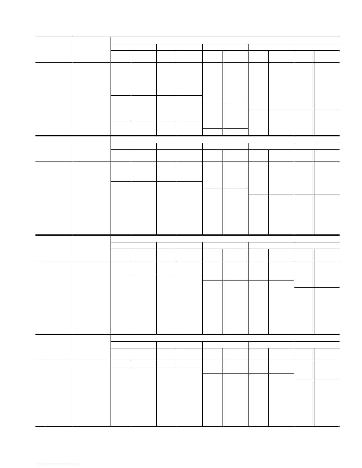
Table 7—Model 58ZAV Orifice Size and Manifold Pressure for Correct Input
(Tabulated Data Based on 23,000 BTUH Per Burner, Derated 4% per 1000 Ft Above Sea Level)*
ALTITUDE
RANGE
(FT)
0 925 42 3.4 42 3.5 42 3.6 42 3.7 42 3.8
to 975 43 3.7 43 3.8 42 3.2 42 3.3 42 3.4
2000 1025 43 3.3 43 3.4 43 3.6 43 3.7 43 3.8
U.S.A. and Canada
ALTITUDE
RANGE
(FT)
U.S.A 775 42 3.7 42 3.8 41 3.5 41 3.6 41 3.8
Altitudes 800 42 3.4 42 3.6 42 3.7 42 3.8 41 3.5
2001 825 42 3.2 42 3.3 42 3.5 42 3.6 42 3.7
to 850 43 3.7 43 3.8 42 3.3 42 3.4 42 3.5
3000 875 43 3.5 43 3.6 43 3.7 42 3.2 42 3.3
or 900 43 3.3 43 3.4 43 3.5 43 3.7 43 3.8
Canada 925 43 3.1 43 3.2 43 3.4 43 3.5 43 3.6
Altitudes 950 43 3.0 43 3.1 43 3.2 43 3.3 43 3.4
U.S.A. and Canada
2000 975 43 2.8 43 2.9 43 3.0 43 3.1 43 3.2
to 1000 43 2.7 43 2.8 43 2.9 43 3.0 43 3.1
4500 1025 43 2.6 43 2.6 43 2.7 43 2.8 43 2.9
ALTITUDE
RANGE
(FT)
3001 825 43 3.5 43 3.6 43 3.7 43 3.8 42 3.2
to 875 43 3.1 43 3.2 43 3.3 43 3.4 43 3.5
U.S.A. Only
4000 925 43 2.8 43 2.9 43 3.0 43 3.0 43 3.1
ALTITUDE
RANGE
(FT)
4001 800 43 3.2 43 3.3 43 3.5 43 3.6 43 3.7
to 850 43 2.9 43 3.0 43 3.1 43 3.2 43 3.3
U.S.A. Only
5000 900 43 2.6 43 2.6 43 2.7 43 2.8 43 2.9
* For size 135-20 only, input is 22,500 Btuh. Deduct 0.1-in. wc from manifold pressure shown in table. Change orifice size if manifold pressure falls below 3.2-in. wc on
altitudes up to 2000 ft, otherwise change orifice size if manifold pressure falls below 2.0-in. wc.
AVG GAS
HEAT VALUE
AT ALTITUDE
(BTU/CU FT)
850 41 3.6 41 3.7 41 3.8 40 3.6 40 3.8
875 42 3.8 41 3.5 41 3.6 41 3.7 41 3.8
900 42 3.5 42 3.7 42 3.8 41 3.5 41 3.6
950 42 3.2 42 3.3 42 3.4 42 3.5 42 3.6
1000 43 3.5 43 3.6 43 3.7 42 3.2 42 3.3
1050 43 3.2 43 3.3 43 3.4 43 3.5 43 3.6
1075 44 3.5 44 3.6 43 3.2 43 3.3 43 3.4
1100 44 3.3 44 3.4 44 3.5 43 3.2 43 3.3
AVG GAS
HEAT VALUE
AT ALTITUDE
(BTU/CU FT)
AVG GAS
HEAT VALUE
AT ALTITUDE
(BTU/CU FT)
750 42 3.4 42 3.6 42 3.7 42 3.8 41 3.5
775 42 3.2 42 3.3 42 3.5 42 3.6 42 3.7
800 43 3.7 43 3.8 42 3.2 42 3.3 42 3.4
850 43 3.3 43 3.4 43 3.5 43 3.6 43 3.7
900 43 2.9 43 3.0 43 3.1 43 3.2 43 3.3
950 43 2.6 43 2.7 43 2.8 43 2.9 43 3.0
975 43 2.5 43 2.6 43 2.7 43 2.7 43 2.8
1000 43 2.4 43 2.4 43 2.5 43 2.6 43 2.7
AVG GAS
HEAT VALUE
AT ALTITUDE
(BTU/CU FT)
725 42 3.2 42 3.3 42 3.5 42 3.6 42 3.7
750 43 3.7 43 3.8 42 3.2 42 3.3 42 3.4
775 43 3.4 43 3.6 43 3.7 43 3.8 42 3.2
825 43 3.0 43 3.1 43 3.2 43 3.4 43 3.5
875 43 2.7 43 2.8 43 2.9 43 3.0 43 3.1
925 43 2.4 43 2.5 43 2.6 43 2.7 43 2.8
950 43 2.3 43 2.4 43 2.5 43 2.5 43 2.6
0.58 0.60 0.62 0.64 0.66
Orifice
Orifice
Orifice
Orifice
Manifold
No.
Pressure
0.58 0.60 0.62 0.64 0.66
Manifold
No.
Pressure
0.58 0.60 0.62 0.64 0.66
Manifold
No.
Pressure
0.58 0.60 0.62 0.64 0.66
Manifold
No.
Pressure
Orifice
No.
Orifice
No.
Orifice
No.
Orifice
No.
SPECIFIC GRAVITY OF NATURAL GAS
Manifold
Pressure
SPECIFIC GRAVITY OF NATURAL GAS
Manifold
Pressure
SPECIFIC GRAVITY OF NATURAL GAS
Manifold
Pressure
SPECIFIC GRAVITY OF NATURAL GAS
Manifold
Pressure
Orifice
No.
Orifice
No.
Orifice
No.
Orifice
No.
Manifold
Pressure
Manifold
Pressure
Manifold
Pressure
Manifold
Pressure
Orifice
No.
Orifice
No.
Orifice
No.
Orifice
No.
Manifold
Pressure
Manifold
Pressure
Manifold
Pressure
Manifold
Pressure
Orifice
No.
Orifice
No.
Orifice
No.
Orifice
No.
Manifold
Pressure
Manifold
Pressure
Manifold
Pressure
Manifold
Pressure
15
Page 16
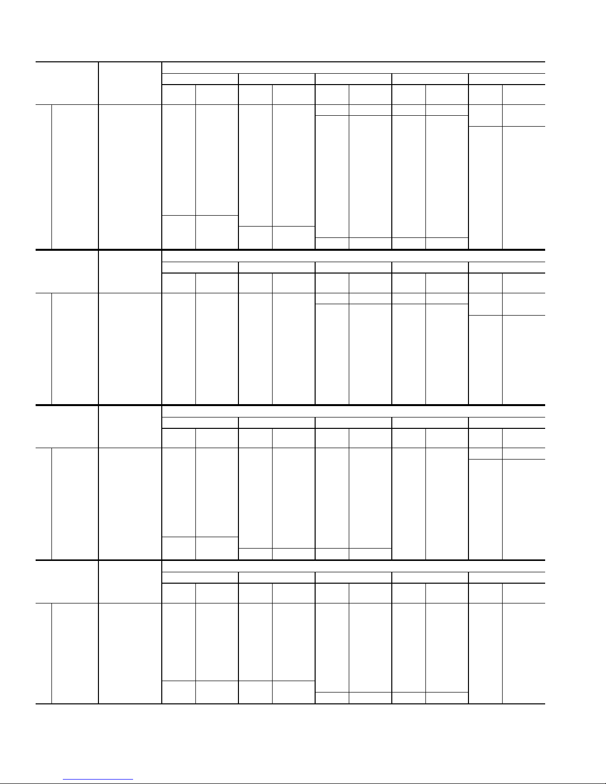
Table 7—Model 58ZAV Orifice Size and Manifold Pressure for Correct Input Continued
(Tabulated Data Based on 23,000 BTUH Per Burner, Derated 4% per 1000 Ft Above Sea Level)*
ALTITUDE
RANGE
(FT)
5001 800 43 2.8 43 2.9 43 3.0 43 3.1 43 3.2
to 850 43 2.5 43 2.6 43 2.7 43 2.8 43 2.8
U.S.A. Only
6000 900 43 2.2 43 2.3 43 2.4 43 2.5 43 2.5
ALTITUDE
RANGE
(FT)
6001 725 43 3.0 43 3.1 43 3.2 43 3.3 43 3.4
to 775 43 2.6 43 2.7 43 2.8 43 2.9 43 3.0
U.S.A. Only
7000 825 43 2.3 43 2.4 43 2.5 43 2.5 43 2.6
ALTITUDE
RANGE
(FT)
7001 700 43 2.7 43 2.8 43 2.9 43 3.0 43 3.1
to 750 43 2.4 43 2.5 43 2.6 43 2.6 43 2.7
U.S.A. Only
8000 800 43 2.1 43 2.2 43 2.2 43 2.3 43 2.4
ALTITUDE
RANGE
(FT)
8001 650 43 2.7 43 2.8 43 2.9 43 3.0 43 3.1
to 700 43 2.4 43 2.4 43 2.5 43 2.6 43 2.7
U.S.A. Only
9000 750 43 2.0 43 2.1 43 2.2 43 2.3 43 2.3
* For size 135-20 only, input is 22,500 Btuh. Deduct 0.1-in. wc from manifold pressure shown in table. Change orifice size if manifold pressure falls below 3.2-in. wc on
altitudes up to 2000 ft, otherwise change orifice size if manifold pressure falls below 2.0-in. wc.
AVG GAS
HEAT VALUE
AT ALTITUDE
(BTU/CU FT)
700 43 3.7 43 3.8 42 3.2 42 3.3 42 3.4
725 43 3.4 43 3.6 43 3.7 43 3.8 42 3.2
750 43 3.2 43 3.3 43 3.4 43 3.5 43 3.6
775 43 3.0 43 3.1 43 3.2 43 3.3 43 3.4
825 43 2.7 43 2.7 43 2.8 43 2.9 43 3.0
875 43 2.4 43 2.4 43 2.5 43 2.6 43 2.7
925 43 2.1 43 2.2 43 2.3 43 2.3 43 2.4
950 48 3.8 43 2.1 43 2.1 43 2.2 43 2.3
975 48 3.6 48 3.7 43 2.0 43 2.1 43 2.2
1000 48 3.4 48 3.5 48 3.6 48 3.7 43 2.1
AVG GAS
HEAT VALUE
AT ALTITUDE
(BTU/CU FT)
650 43 3.7 43 3.8 42 3.2 42 3.3 42 3.5
675 43 3.4 43 3.5 43 3.7 43 3.8 42 3.2
700 43 3.2 43 3.3 43 3.4 43 3.5 43 3.6
750 43 2.8 43 2.9 43 3.0 43 3.1 43 3.2
800 43 2.4 43 2.5 43 2.6 43 2.7 43 2.8
850 43 2.2 43 2.2 43 2.3 43 2.4 43 2.5
875 43 2.0 43 2.1 43 2.2 43 2.3 43 2.3
AVG GAS
HEAT VALUE
AT ALTITUDE
(BTU/CU FT)
625 43 3.4 43 3.6 43 3.7 43 3.8 42 3.2
650 43 3.2 43 3.3 43 3.4 43 3.5 43 3.6
675 43 3.0 43 3.1 43 3.2 43 3.3 43 3.4
725 43 2.6 43 2.6 43 2.7 43 2.8 43 2.9
775 43 2.2 43 2.3 43 2.4 43 2.5 43 2.5
825 48 3.7 43 2.0 43 2.1 43 2.2 43 2.2
850 48 3.5 48 3.6 48 3.7 43 2.1 43 2.1
AVG GAS
HEAT VALUE
AT ALTITUDE
(BTU/CU FT)
600 43 3.2 43 3.3 43 3.4 43 3.5 43 3.6
625 43 3.0 43 3.1 43 3.2 43 3.3 43 3.4
675 43 2.5 43 2.6 43 2.7 43 2.8 43 2.9
725 43 2.2 43 2.3 43 2.3 43 2.4 43 2.5
775 48 3.6 48 3.7 43 2.1 43 2.1 43 2.2
800 48 3.4 48 3.5 48 3.6 48 3.7 43 2.0
0.58 0.60 0.62 0.64 0.66
Orifice
No.
Orifice
No.
Orifice
No.
Orifice
No.
Manifold
Pressure
0.58 0.60 0.62 0.64 0.66
Manifold
Pressure
0.58 0.60 0.62 0.64 0.66
Manifold
Pressure
0.58 0.60 0.62 0.64 0.66
Manifold
Pressure
Orifice
No.
Orifice
No.
Orifice
No.
Orifice
No.
SPECIFIC GRAVITY OF NATURAL GAS
Manifold
Pressure
SPECIFIC GRAVITY OF NATURAL GAS
Manifold
Pressure
SPECIFIC GRAVITY OF NATURAL GAS
Manifold
Pressure
SPECIFIC GRAVITY OF NATURAL GAS
Manifold
Pressure
Orifice
No.
Orifice
No.
Orifice
No.
Orifice
No.
Manifold
Pressure
Manifold
Pressure
Manifold
Pressure
Manifold
Pressure
Orifice
No.
Orifice
No.
Orifice
No.
Orifice
No.
Manifold
Pressure
Manifold
Pressure
Manifold
Pressure
Manifold
Pressure
Orifice
No.
Orifice
No.
Orifice
No.
Orifice
No.
Manifold
Pressure
Manifold
Pressure
Manifold
Pressure
Manifold
Pressure
16
Page 17
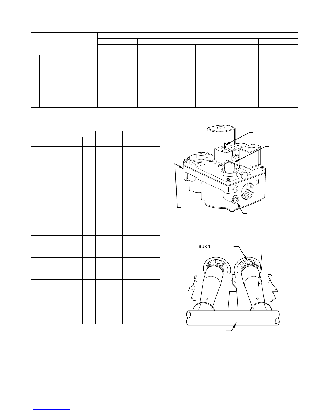
Table 7—Model 58ZAV Orifice Size and Manifold Pressure for Correct Input Continued
(Tabulated Data Based on 23,000 BTUH Per Burner, Derated 4% per 1000 Ft Above Sea Level)*
ALTITUDE
RANGE
(FT)
AVG GAS
HEAT VALUE
AT ALTITUDE
(BTU/CU FT)
0.58 0.60 0.62 0.64 0.66
Orifice
No.
Manifold
Pressure
Orifice
No.
575 43 3.0 43 3.1 43 3.2 43 3.3 43 3.4
600 43 2.7 43 2.8 43 2.9 43 3.0 43 3.1
9001 625 43 2.5 43 2.6 43 2.7 43 2.8 43 2.8
650 43 2.3 43 2.4 43 2.5 43 2.6 43 2.6
to 675 43 2.1 43 2.2 43 2.3 43 2.4 43 2.4
700 48 3.8 43 2.1 43 2.1 43 2.2 43 2.3
U.S.A. Only
10,000 725 48 3.5 48 3.6 48 3.7 43 2.1 43 2.1
750 49 3.8 48 3.4 48 3.5 48 3.6 48 3.7
775 49 3.6 49 3.7 49 3.8 48 3.4 48 3.5
* For size 135-20 only, input is 22,500 Btuh. Deduct 0.1-in. wc from manifold pressure shown in table. Change orifice size if manifold pressure falls below 3.2-in. wc on
altitudes up to 2000 ft, otherwise change orifice size if manifold pressure falls below 2.0-in. wc.
SPECIFIC GRAVITY OF NATURAL GAS
Manifold
Pressure
Orifice
No.
Manifold
Pressure
Orifice
No.
Manifold
Pressure
Orifice
No.
Manifold
Pressure
Table 9—Gas Rate (Cu Ft/Hr)
SECONDS
FOR 1
REVOLUTION
10
11
12
13
14
15
16
17
18
19
20
21
22
23
24
25
26
27
28
29
30
31
32
33
34
35
36
37
38
39
40
41
42
43
44
45
46
47
48
49
SIZE OF TEST DIAL
1
cu ft2cu ft5cu ft
360
720
655
600
555
514
480
450
424
400
379
360
343
327
313
300
288
277
267
257
248
240
232
225
218
212
206
200
195
189
185
180
176
172
167
164
160
157
153
150
147
1800
1636
1500
1385
1286
1200
1125
1059
1000
947
900
857
818
783
750
720
692
667
643
621
600
581
563
545
529
514
500
486
474
462
450
439
429
419
409
400
391
383
375
367
327
300
277
257
240
225
212
200
189
180
171
164
157
150
144
138
133
129
124
120
116
113
109
106
103
100
97
95
92
90
88
86
84
82
80
78
76
75
73
SECONDS
FOR 1
REVOLUTION
50
51
52
53
54
55
56
57
58
59
60
62
64
66
68
70
72
74
76
78
80
82
84
86
88
90
92
94
96
98
100
102
104
106
108
110
112
116
120
SIZE OF TEST DIAL
1
cu ft2cu ft5cu ft
72
144
141
138
136
133
131
129
126
124
122
120
116
112
109
106
103
100
97
95
92
90
88
86
84
82
80
78
76
75
74
72
71
69
68
67
65
64
62
60
360
355
346
340
333
327
321
316
310
305
300
290
281
273
265
257
250
243
237
231
225
220
214
209
205
200
196
192
188
184
180
178
173
170
167
164
161
155
150
71
69
68
67
65
64
63
62
61
60
58
56
54
53
51
50
48
47
46
45
44
43
42
41
40
39
38
38
37
36
35
35
34
33
33
32
31
30
INLET
PRESSURE TAP
Fig. 17—Redundant Automatic Gas Control Valve
BURNER FLAME
ON AND
OFF SWITCH
GAS
PRESSURE
REGULATOR
ADJUSTMENT
MANIFOLD
PRESSURE TAP
A95618
BURNER
2. Set temperature rise.
Furnace must operate within range of temperature rise speci-
fied on the unit rating plate. Determine the air temperature rise
as follows.
a. Place duct thermometers in return and supply ducts as near
furnace as possible. Be sure thermometers do not "see" heat
exchangers so that radiant heat does not affect thermometer
readings. This is particularly important with straight-run
ducts.
MANIFOLD
A89020
Fig. 18—Burner Flame
b. When thermometer readings stabilize, subtract return-air
temperature from supply-air temperature to determine temperature rise.
c. Adjust air temperature rise by adjusting blower speed.
Increase blower speed to reduce temperature rise. Decrease
blower speed to increase temperature rise.
17
Page 18
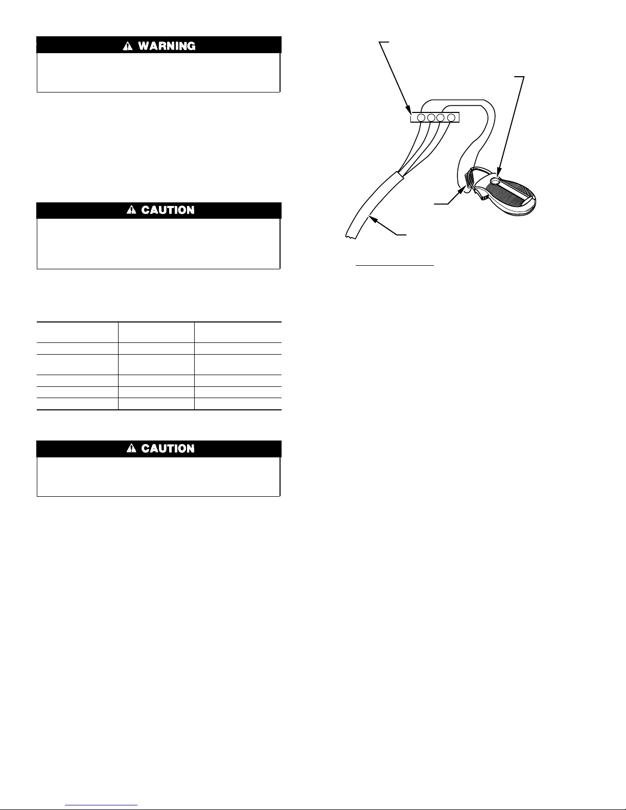
Disconnect the electrical power before changing the speed
tap. Failure to follow this warning could result in personal
injury.
d. To change blower motor speed selections for heating mode
remove blower motor lead from control board HEAT
terminal. (See Fig. 13.) Select desired blower motor speed
lead from 1 of the other terminals and relocate it to HEAT
terminal. See Table 10 for lead color identification. Reconnect original lead on SPARE terminal.
Follow this same procedure for proper selection of COOL
speed selection.
THERMOSTAT SUBBASE
TERMINALS WITH
THERMOSTAT REMOVED
HOOK-AROUND
VOLT/AMMETER
R Y W G
10 TURNS
If Model 58ZAV115-22 is installed in 0.50-in. wc or lower
static pressure ductwork, evaporator coil condensate blow off
can occur during cooling operation. When installed in this
msnner, do not use high blower speed tap for cooling.
Table 10—Speed Selector
COLOR SPEED
Black High COOL
Yellow (When
present)
Blue Medium-Low HEAT
Red Low SPARE
White Common C
Medium-High SPARE
Recheck temperature rise. It must be within limits specified
on unit rating plate. Recommended operation is at midpoint of
rise or above.
3. Set thermostat heat anticipator.
The thermostat heat anticipation must be set to match the amp
draw of the electrical components in the R-W circuit. Accurate
amp draw readings can be obtained at thermostat subbase
terminals R and W. Fig. 19 illustrates an easy method of
obtaining the actual amp draw. The amp reading should be
taken after the blower motor has started. See the thermostat
manufacturer’s instructions for adjusting the heat anticipator
and for varying the heating cycle length.
NOTE: When using an electronic thermostat, set cycle rate for 3
cycles per hr.
FACTORY-
ATTACHED TO
OM
FROM UNIT 24-VOLT
TERMINAL BLOCK
EXAMPLE:
5.0 AMPS ON AMMETER
10 TURNS AROUND JAWS
= 0.5 AMPS FOR THERMOSTAT SETTING
Fig. 19—Amp Draw Check With Ammeter
CHECK SAFETY CONTROLS
The flame sensor, gas valve, and pressure switch were all checked
in the Start-up Procedures section as part of normal operation.
1. Check primary limit control.
This control shuts off the combustion control system and
energizes the circulating-air blower motor if the furnace
overheats.
The preferred method of checking the limit control is to
gradually block off the return air after the furnace has been
operating for a period of at least 5 minutes. As soon as the
limit has shut off the burners, the return-air opening should be
unblocked. By using this method to check the limit control, it
can be established that the limit is functioning properly and
operates if there is a motor failure.
2. Check draft safeguard switch.
The purpose of this control is to permit the safe shutdown of
the furnace during certain blocked vent conditions.
a. Disconnect power to furnace and remove vent connector
from furnace outlet collar. Be sure to allow time for vent
pipe to cool down before removing.
b. Restore power to furnace and set room thermostat above
room temperature.
c. After normal start-up, allow furnace to operate for 2
minutes, then block flue outlet 100 percent. Furnace should
cycle off within 2 minutes.
d. Remove blockage and reconnect vent pipe to furnace outlet
collar.
e. Wait 5 minutes and then reset draft safeguard switch.
3. Check pressure switch.
This control proves operation of draft inducer blower.
a. Turn off 115-v power to furnace.
b. Remove control door and disconnect inducer motor lead
wires from wire harness.
c. Turn on 115-v power to furnace.
d. Set thermostat to "call for heat" and wait 1 minute. When
pressure switch is functioning properly, hot surface ignitor
should NOT glow and control board diagnostic light
18
A80201
Page 19

flashes a 31 fault. If hot surface ignitor glows when inducer
motor is disconnected, shut down furnace immediately.
Determine reason pressure switch did not function properly
and correct condition.
e. Turn off 115-v power to furnace.
f. Reconnect inducer motor wires, replace control door, and
turn on 115-v power to furnace.
4. Check auxiliary limits (when used).
a. Turn off 115-v power to furnace.
b. Remove blower access door.
c. Disconnect red motor lead at blower speed selector. Mark
terminal for proper reconnection.
d. Replace blower access door.
e. Turn on 115-v power to furnace. Be sure room thermostat
is calling for heat.
f. Allow furnace to operate until auxiliary limit activates, but
DO NOT operate furnace longer than 4 minutes.
SERVICE TRAINING
g. If furnace operates for 4 minutes, check/replace limit
switch(es).
h. Turn off 115-v power to furnace.
i. Remove blower access door.
j. Reconnect red motor lead, reset switch, and replace door.
k. Turn on 115-v power to furnace.
CHECKLIST
1. Put away tools, instruments, and clean up debris.
2. Verify manual reset switches have continuity.
3. Ensure blower and control access doors are properly installed.
4. Cycle test furnace with room thermostat.
5. Check operation of accessories per manufacturer’s instructions.
6. Review User’s Manual with owner.
7. Leave literature packet near furnace.
Packaged Service Training programs are an excellent way to increase your
knowledge of the equipment discussed in this manual, including:
• Unit Familiarization • Maintenance
• Installation Overview • Operating Sequence
A large selection of product, theory, and skills programs is available, using popular
video-based formats and materials. All include video and/or slides, plus companion
book.
Classroom Service Training plus "hands-on" the products in our labs can mean
increased confidence that really pays dividends in faster troubleshooting, fewer
callbacks. Course descriptions and schedules are in our catalog.
CALL FOR FREE CATALOG 1-800-962-9212
[ ] Packaged Service Training [ ] Classroom Service Training
A94328
19
Page 20

Copyright 1997 CARRIER Corp. • 7310 W. Morris St. • Indianapolis, IN 46231 58zav9si
Manufacturer reserves the right to discontinue, or change at any time, specifications or designs without notice and without incurring obligations.
Book 1 4
Tab 6a 8a
PC 101 Catalog No. 535-860 Printed in U.S.A. Form 58ZAV-9SI Pg 20 1-97 Replaces: 58ZAV-8SI
 Loading...