

Carrier WeatherMaker 50AY 020-060, WeatherMaker 48AJ 020-060, WeatherMaker 50AJ 020-060, WeatherMaker 48A4 020-060, WeatherMaker 48AK 020-060 Operation And Service Manual
...
with COMFORTLINK™ Version 5.x Controls
Controls, Start-Up, Operation,
Service and Troubleshooting
CONTENTS
Page
SAFETY CONSIDERATIONS . . . . . . . . . . . . . . . . . . . . . . . . .2
GENERAL . . . . . . . . . . . . . . . . . . . . . . . . . . . . . . . . . . . . . . . . . . . 3
Conventions Used in this Manual. . . . . . . . . . . . . . . . . . . . 3
BASIC CONTROL USAGE. . . . . . . . . . . . . . . . . . . . . . . . . . 3-6
ComfortLink Controls . . . . . . . . . . . . . . . . . . . . . . . . . . . . . . . 3
Scrolling Marquee . . . . . . . . . . . . . . . . . . . . . . . . . . . . . . . . . . . 4
Accessory Navigator™ Display. . . . . . . . . . . . . . . . . . . . . . 4
Operation. . . . . . . . . . . . . . . . . . . . . . . . . . . . . . . . . . . . . . . . . . . . 4
System Pilot™ Interface . . . . . . . . . . . . . . . . . . . . . . . . . . . . . 5
CCN Tables and Display . . . . . . . . . . . . . . . . . . . . . . . . . . . . .5
• GENERICS STATUS DISPLAY TABLE
START-UP . . . . . . . . . . . . . . . . . . . . . . . . . . . . . . . . . . . . . . . . 7-27
Unit Preparation . . . . . . . . . . . . . . . . . . . . . . . . . . . . . . . . . . . . .7
Unit Setup . . . . . . . . . . . . . . . . . . . . . . . . . . . . . . . . . . . . . . . . . . . 7
Internal Wiring. . . . . . . . . . . . . . . . . . . . . . . . . . . . . . . . . . . . . . .7
Accessory Installation. . . . . . . . . . . . . . . . . . . . . . . . . . . . . . . 7
Crankcase Heaters . . . . . . . . . . . . . . . . . . . . . . . . . . . . . . . . . .7
Evaporator Fan . . . . . . . . . . . . . . . . . . . . . . . . . . . . . . . . . . . . . .7
Controls . . . . . . . . . . . . . . . . . . . . . . . . . . . . . . . . . . . . . . . . . . . . . 7
Gas Heat . . . . . . . . . . . . . . . . . . . . . . . . . . . . . . . . . . . . . . . . . . . .7
CONTROLS QUICK START . . . . . . . . . . . . . . . . . . . . . . 27-29
Two-Stage Constant Volume Units with
Mechanical Thermostat . . . . . . . . . . . . . . . . . . . . . . . . . . 27
Two-Stage Constant Volume Units with
Space Sensor . . . . . . . . . . . . . . . . . . . . . . . . . . . . . . . . . . . .27
Variable Air Volume Units Using Return Air Sensor
or Space Temperature Sensor. . . . . . . . . . . . . . . . . . . .28
Multi-Stage Constant Volume Units with
Mechanical Thermostat . . . . . . . . . . . . . . . . . . . . . . . . . . 28
Multi-Stage Constant Volume Units with
Space Sensor . . . . . . . . . . . . . . . . . . . . . . . . . . . . . . . . . . . .28
Economizer Options. . . . . . . . . . . . . . . . . . . . . . . . . . . . . . . .28
Indoor Air Quality Options. . . . . . . . . . . . . . . . . . . . . . . . . . 29
Exhaust Options. . . . . . . . . . . . . . . . . . . . . . . . . . . . . . . . . . . . 29
Programming Operating Schedules . . . . . . . . . . . . . . . .29
SERVICE TEST . . . . . . . . . . . . . . . . . . . . . . . . . . . . . . . . . . 29,30
General. . . . . . . . . . . . . . . . . . . . . . . . . . . . . . . . . . . . . . . . . . . . .29
Service Test Mode Logic . . . . . . . . . . . . . . . . . . . . . . . . . . .29
Independent Outputs . . . . . . . . . . . . . . . . . . . . . . . . . . . . . . . 30
Fans in Service Test Mode . . . . . . . . . . . . . . . . . . . . . . . . .30
Cooling in Service Test Mode. . . . . . . . . . . . . . . . . . . . . . .30
Heating in Service Test Mode. . . . . . . . . . . . . . . . . . . . . . .30
THIRD PARTY CONTROL . . . . . . . . . . . . . . . . . . . . . . . . 31,32
Thermostat . . . . . . . . . . . . . . . . . . . . . . . . . . . . . . . . . . . . . . . . .31
Alarm Output . . . . . . . . . . . . . . . . . . . . . . . . . . . . . . . . . . . . . . .31
Remote Switch . . . . . . . . . . . . . . . . . . . . . . . . . . . . . . . . . . . . .31
VFD Control . . . . . . . . . . . . . . . . . . . . . . . . . . . . . . . . . . . . . . . . 31
Supply Air Reset . . . . . . . . . . . . . . . . . . . . . . . . . . . . . . . . . . .31
Demand Limit Control . . . . . . . . . . . . . . . . . . . . . . . . . . . . . .31
Demand Controlled Ventilation Control . . . . . . . . . . . . .31
CONTROLS OPERATION . . . . . . . . . . . . . . . . . . . . . . . . 32-75
Modes . . . . . . . . . . . . . . . . . . . . . . . . . . . . . . . . . . . . . . . . . . . . . .32
• SYSTEM MODES
• HVAC MODES
WEATHERMAKER
48/50AJ,AK,AW,AY,A2,A3,A4,A5020-060
Single Package Large Rooftop Units
Page
Unit Configuration Submenu . . . . . . . . . . . . . . . . . . . . . . . 35
Cooling Control . . . . . . . . . . . . . . . . . . . . . . . . . . . . . . . . . . . . 37
• SETTING UP THE SYSTEM
• MACHINE DEPENDENT CONFIGURATIONS
• SET POINTS
• SUPPLY AIR RESET CONFIGURATION
• COOLING CONFIGURATION
• COMPRESSOR SAFETIES
• COMPRESSOR TIME GUARDS
• COOL MODE SELECTION PROCESS
• COOLING MODE DIAGNOSTIC HELP
• SUMZ COOLING ALGORITHM
• DEMAND LIMIT CONTROL
• HEAD PRESSURE CONTROL
• ECONOMIZER INTEGRATION WITH
MECHANICAL COOLING
Heating Control . . . . . . . . . . . . . . . . . . . . . . . . . . . . . . . . . . . . 50
• SETTING UP THE SYSTEM
• HEAT MODE SELECTION PROCESS
• TEMPERATURE DRIVEN HEAT MODE
EVALUATION
• HEAT MODE DIAGNOSTIC HELP
• INTEGRATED GAS CONTROL BOARD LOGIC
• RELOCATE SAT SENSOR FOR HEATING IN
LINKAGE SYSTEMS
• MORNING WARM UP
• TEMPERING MODE
Static Pressure Control . . . . . . . . . . . . . . . . . . . . . . . . . . . . 57
•OPERATION
• SETTING UP THE SYSTEM
• STATIC PRESSURE RESET OPERATION
• RELATED POINTS
Fan Status Monitoring. . . . . . . . . . . . . . . . . . . . . . . . . . . . . . 59
• GENERAL
• SETTING UP THE SYSTEM
• SUPPLY FAN STATUS MONITORING LOGIC
Dirty Filter Switch . . . . . . . . . . . . . . . . . . . . . . . . . . . . . . . . . . 60
Economizer . . . . . . . . . . . . . . . . . . . . . . . . . . . . . . . . . . . . . . . . 60
• SETTING UP THE SYSTEM
• ECONOMIZER OPERATION
• UNOCCUPIED ECONOMIZER FREE COOLING
• ECONOMIZER OPERATION CONFIGURATION
• ECONOMIZER DIAGNOSTIC HELP
Building Pressure Control. . . . . . . . . . . . . . . . . . . . . . . . . . 63
• BUILDING PRESSURE CONFIGURATION
• CONSTANT VOLUME 2-STAGE CONTROL
OPERATION
• MULTIPLE POWER EXHAUST STAGE BUILDING
PRESSURE CONTROL OPERATION
• VFD POWER EXHAUST BUILDING PRESSURE
CONTROL
Smoke Control Modes. . . . . . . . . . . . . . . . . . . . . . . . . . . . . . 66
• FIRE-SMOKE INPUTS
• AIRFLOW CONTROL DURING THE
FIRE-SMOKE MODES
• RELEVANT ITEMS
®
Manufacturer reserves the right to discontinue, or change at any time, specifications or designs without notice and without incurring obligations.
Catalog No. 04-53480077-01 Printed in U.S.A. Form 48/50A-9T Pg 1 6-10 Replaces: 48/50A-7T
CONTENTS (cont)
Indoor Air Quality Control. . . . . . . . . . . . . . . . . . . . . . . . . . 67
•OPERATION
• SETTING UP THE SYSTEM
• PRE-OCCUPANCY PURGE
Dehumidification and Reheat . . . . . . . . . . . . . . . . . . . . . . 69
• SETTING UP THE SYSTEM
•OPERATION
Temperature Compensated Start. . . . . . . . . . . . . . . . . . . 71
• SETTING UP THE SYSTEM
• TEMPERATURE COMPENSATED START LOGIC
Carrier Comfort Network
Alert Limit Configuration. . . . . . . . . . . . . . . . . . . . . . . . . . . 72
Sensor Trim Configuration . . . . . . . . . . . . . . . . . . . . . . . . . 73
Discrete Switch Logic Configuration. . . . . . . . . . . . . . . 74
Display Configuration. . . . . . . . . . . . . . . . . . . . . . . . . . . . . . 74
Remote Control Switch Input. . . . . . . . . . . . . . . . . . . . . . . 74
Hot Gas Bypass. . . . . . . . . . . . . . . . . . . . . . . . . . . . . . . . . . . . 75
Space Temperature Offset . . . . . . . . . . . . . . . . . . . . . . . . . 75
TIME CLOCK CONFIGURATION . . . . . . . . . . . . . . . . . 75-77
TROUBLESHOOTING . . . . . . . . . . . . . . . . . . . . . . . . . . 77-101
Complete Unit Stoppage . . . . . . . . . . . . . . . . . . . . . . . . . . . 77
Single Circuit Stoppage. . . . . . . . . . . . . . . . . . . . . . . . . . . . 77
Service Analysis . . . . . . . . . . . . . . . . . . . . . . . . . . . . . . . . . . . 77
Restart Procedure . . . . . . . . . . . . . . . . . . . . . . . . . . . . . . . . . 77
Thermistor Troubleshooting . . . . . . . . . . . . . . . . . . . . . . . 77
Transducer Troubleshooting . . . . . . . . . . . . . . . . . . . . . . . 78
Forcing Inputs and Outputs. . . . . . . . . . . . . . . . . . . . . . . . 90
Run Status Menu. . . . . . . . . . . . . . . . . . . . . . . . . . . . . . . . . . . 90
• AUTO VIEW OF RUN STATUS
• ECONOMIZER RUN STATUS
• COOLING INFORMATION
• MODE TRIP HELPER
• CCN/LINKAGE DISPLAY TABLE
• COMPRESSOR RUN HOURS DISPLAY TABLE
• COMPRESSOR STARTS DISPLAY TABLE
• TIME GUARD DISPLAY TABLE
• SOFTWARE VERSION NUMBERS DISPLAY TABLE
Alarms and Alerts. . . . . . . . . . . . . . . . . . . . . . . . . . . . . . . . . . 93
MAJOR SYSTEM COMPONENTS. . . . . . . . . . . . . . 101-127
General . . . . . . . . . . . . . . . . . . . . . . . . . . . . . . . . . . . . . . . . . . . 101
Factory-Installed Components . . . . . . . . . . . . . . . . . . . . 101
Accessory Control Components . . . . . . . . . . . . . . . . . . 124
SERVICE. . . . . . . . . . . . . . . . . . . . . . . . . . . . . . . . . . . . . . 128-139
Service Access . . . . . . . . . . . . . . . . . . . . . . . . . . . . . . . . . . . 128
Cleaning . . . . . . . . . . . . . . . . . . . . . . . . . . . . . . . . . . . . . . . . . . 128
Lubrication . . . . . . . . . . . . . . . . . . . . . . . . . . . . . . . . . . . . . . . 130
Evaporator Fan Performance Adjustment . . . . . . . . . 130
Evaporator Fan Coupling Assembly. . . . . . . . . . . . . . . 130
Evaporator Fan Service and Replacement . . . . . . . . 131
Belt Tension Adjustment. . . . . . . . . . . . . . . . . . . . . . . . . . 131
Evaporator-Fan Motor Replacement. . . . . . . . . . . . . . . 131
Condenser-Fan Adjustment. . . . . . . . . . . . . . . . . . . . . . . 132
Four-Inch Filter Replacement . . . . . . . . . . . . . . . . . . . . . 132
Power Failure . . . . . . . . . . . . . . . . . . . . . . . . . . . . . . . . . . . . . 132
Refrigerant Charge. . . . . . . . . . . . . . . . . . . . . . . . . . . . . . . . 132
Thermostatic Expansion Valve (TXV). . . . . . . . . . . . . . 132
Gas Valve Adjustment . . . . . . . . . . . . . . . . . . . . . . . . . . . . 132
Main Burners . . . . . . . . . . . . . . . . . . . . . . . . . . . . . . . . . . . . . 139
Filter Drier . . . . . . . . . . . . . . . . . . . . . . . . . . . . . . . . . . . . . . . . 139
Replacement Parts. . . . . . . . . . . . . . . . . . . . . . . . . . . . . . . . 139
APPENDIX A — LOCAL DISPLAY TABLES . . . . 140-147
APPENDIX B — CCN TABLES . . . . . . . . . . . . . . . . . 148-160
APPENDIX C — VFD INFORMATION. . . . . . . . . . . 161-169
APPENDIX D — MODE SELECTION
PROCESS. . . . . . . . . . . . . . . . . . . . . . . . . . . . . . . . . . . . . . . 170
APPENDIX E — UPC OPEN CONTROLLER. . . . 171-182
INDEX. . . . . . . . . . . . . . . . . . . . . . . . . . . . . . . . . . . . . . . . . . . . . 183
CONTROLS SET POINT AND
CONFIGURATION LOG. . . . . . . . . . . . . . . . . . CL-1 to CL-5
UNIT START-UP CHECKLIST . . . . . . . . . . . . . . . . . . . . . CL-6
®
(CCN) System. . . . . . . . . . . 71
Page
SAFETY CONSIDERATIONS
Installation and servicing of air-conditioning equipment can
be hazardous due to system pressure and electrical components. Only trained and qualified service personnel should install, repair, or service air-conditioning equipment. Untrained
personnel can perform the basic maintenance functions of replacing filters. Trained service personnel should perform all
other operations.
When working on air-conditioning equipment, observe precautions in the literature, tags and labels attached to the unit,
and other safety precautions that may apply. Follow all safety
codes. Wear safety glasses and work gloves. Use quenching
cloth for unbrazing operations. Have fire extinguishers available for all brazing operations.
WARNING
Before performing service or maintenance operation on
unit turn off and lock off main power switch to unit.
Electrical shock can cause personal injury and death.
Shut off all power to this equipment during installation
and service. The unit may have an internal non-fused
disconnect or a field-installed disconnect. Note that the
unit may also be equipped with a convenience outlet,
that this outlet is wired to the line side of the unitmounted disconnect and will remain hot when the
disconnect in the unit is off. There is a separate fuse/
disconnect for the convenience outlet.
CAUTION
Puron® refrigerant (R-410A) systems operate at higher
pressures than standard R-22 systems. Do not use R-22 service equipment or components on Puron refrigerant equipment. If service equipment is not rated for Puron
refrigerant, equipment damage or personal injury may
result.
CAUTION
This unit uses a microprocessor-based electronic control
system. Do not use jumpers or other tools to short out com-
ponents or to bypass or otherwise depart from recommended procedures. Any short-to-ground of the control
board or accompanying wiring may destroy the electronic
modules or electrical components.
WARNING
1. Improper installation, adjustment, alteration, service,
or maintenance can cause property damage, personal
injury, or loss of life. Refer to the User’s Information
Manual provided with this unit for more details.
2. Do not store or use gasoline or other flammable vapors and liquids in the vicinity of this or any other
appliance.
What to do if you smell gas:
1. DO NOT try to light any appliance.
2. DO NOT touch any electrical switch, or use any phone
in your building.
3. IMMEDIATELY call your gas supplier from a neighbor’s phone. Follow the gas supplier’s instructions.
4. If you cannot reach your gas supplier call the fire
department.
2
GENERAL
ENTER
ESCAPE
ENTER
This book contains Start-Up, Controls Operation, Troubleshooting and Service information for the 48/50A Series
rooftop units. See Table 1. These units are equipped with
ComfortLink™ controls.
Use this guide in conjunction with the separate installation
instructions packaged with the unit. Refer to the Wiring Diagrams literature for more detailed wiring information.
Table 1 — A Series Product Line
UNIT APPLICATION
48AJ CV Unit with Gas Heat, Vertical Supply
48AK VAV Units with Gas Heat, Vertical Supply
48AW CV Unit with Gas Heat, Horizontal Supply
48AY VAV Unit with Gas Heat, Horizontal Supply
48A2 CV Unit with Gas Heat, Vertical Supply with MCHX Coil
48A3 VAV Unit with Gas Heat, Vertical Supply with MCHX Coil
48A4 CV Unit with Gas Heat, Horizontal Supply with MCHX Coil
48A5 VAV Unit with Gas Heat, Horizontal Supply with MCHX Coil
50AJ CV Unit with Optional Electric Heat, Vertical Supply
50AK VAV Unit with Optional Electric Heat, Vertical Supply
50AW CV Unit with Optional Electric Heat, Horizontal Supply
50AY VAV Unit with Optional Electric Heat, Horizontal Supply
CV Unit with Optional Electric Heat, Vertical Supply with MCHX
50A2
Coil
VAV Unit with Optional Electric Heat, Vertical Supply with MCHX
50A3
Coil
CV Unit with Optional Electric Heat, Horizontal Supply with
50A4
MCHX Coil
VAV Unit with Optional Electric Heat, Horizontal Supply with
50A5
MCHX Coil
LEGEND
CV — Constant Volume
MCHX — Microchannel Heat Exchanger
VAV — Varia bl e Ai r Vol ume
The A Series units provide ventilation, cooling, and heating
(when equipped) in variable air volume (VAV), variable volume
and temperature (VVT®), and constant volume (CV) applications. The A Series units contain the factory-installed Com-
fortLink™ control system which provides full system management. The main base board (MBB) stores hundreds of unit configuration settings and 8 time of day schedules. The MBB also
performs self diagnostic tests at unit start-up, monitors the operation of the unit, and provides alarms and alert information. The
system also contains other optional boards that are connected to
the MBB through the Local Equipment Network (LEN). Information on system operation and status are sent to the MBB processor by various sensors and optional boards that are located at
the unit. Access to the unit controls for configuration, set point
selection, schedule creation, and service can be done through a
unit-mounted scrolling marquee. Access can also be done
through the Carrier Comfort Network
ComfortVIEW™ software, the accessory Navigator™ handheld display, or the System Pilot™ interface.
The ComfortLink system controls all aspects of the rooftop.
It controls the supply-fan motor, compressors, and economizers to maintain the proper temperature conditions. The controls
also cycle condenser fans to maintain suitable head pressure.
All VAV units are equipped with a standard VFD (variable frequency drive) for supply fan speed control and supply duct
pressure control. The ComfortLink controls adjust the speed of
the VFD based on a static pressure sensor input. In addition,
the ComfortLink controls can raise or lower the building pressure using multiple power exhaust fans controlled from economizer damper position or from a building pressure sensor. The
control safeties are continuously monitored to ensure safe operation under all conditions. Sensors include suction pressure
transducers, discharge pressure transducers, and saturated condensing temperature sensors which allow for display of operational pressures and saturation temperatures.
®
(CCN) system using the
A scheduling function, programmed by the user, controls
the unit occupied/unoccupied schedule. Up to 8 different
schedules can be programmed.
The controls also allow the service person to operate a quick
test so that all the controlled components can be checked for
proper operation.
Conventions Used in This Manual — The follow-
ing conventions for discussing configuration points for the local display (scrolling marquee or Navigator accessory) will be
used in this manual.
Point names will be written with the Mode name first, then
any sub-modes, then the point name, each separated by an
arrow symbol (). Names will also be shown in bold and
italics. As an example, the IAQ Economizer Override Position
which is located in the Configuration mode, Indoor Air Quality
Configuration sub-mode, and the Air Quality Set Points
sub-sub-mode, would be written as Configuration
IAQIAQ.SPIQ.O.P. A list of point names can be found in
Appendix A.
This path name will show the user how to navigate through
the local display to reach the desired configuration. The user
would scroll through the modes and submodes using the
and keys. The arrow symbol in the path name represents pressing to move into the next level of the
menu structure.
When a value is included as part of the path name, it will be
shown at the end of the path name after an equals sign. If the
value represents a configuration setting, an explanation will be
shown in parentheses after the value. As an example, Configu-
ration
IAQAQ.CFIQ.AC = 1 (IAQ Analog Input).
Pressing the and keys simultaneously
at any time will display an expanded text description of the fourcharacter point name. The expanded description is shown in the
local display tables (Appendix A).
The CCN point names are also referenced in the local
display tables for users configuring the unit with CCN software
instead of the local display. The CCN tables are located in
Appendix B of this manual.
BASIC CONTROL USAGE
ComfortLink Controls —
system is a comprehensive unit-management system. The control system is easy to access, configure, diagnose and troubleshoot.
The control is flexible, providing two types of constant
volume cooling control sequences, two variable air volume
cooling control sequences, and heating control sequences for
two-stage electric and gas systems, and for multiple-stage gas
heating, in both Occupied and Unoccupied schedule modes.
This control also manages:
• VAV duct pressure (through optional VFD), with reset
• Building pressure through two different power exhaust
schemes
• Condenser fan cycling for mild ambient head pressure
control
• Space ventilation control, in Occupied and Unoccupied
periods, using CO
tilation defined by damper position
• Smoke control functions
• Occupancy schedules
• Occupancy or start/stop sequences based on third party
signals
• Alarm status and history and run time data
• Management of a complete unit service test sequence
sensors or external signals, with ven-
2
The ComfortLink control
3
System diagnostics are enhanced by the use of multiple
ESCAPE
ENTER
ESCAPE
ENTER
ENTER
ESCAPE
Run Status
Service Test
Temperature
Pressures
Setpoints
Inputs
Outputs
Configuration
Time Clock
Operating Modes
Alarms
Alarm Status
ENTER
MODE
ESCAPE
Fig. 1 — Scrolling Marquee
A30-2239
Ru
n Sta
tu
s
S
e
rv
ice
Te
s
t
T
em
p
era
ture
s
P
res
s
ure
s
S
e
tpo
in
ts
In
pu
ts
O
utp
uts
C
on
fig
u
ra
tion
T
im
e
Clo
ck
O
p
er
ating
M
od
es
A
la
rm
s
E
N
T
E
R
E
S
C
M
O
D
E
Ala
rm
Sta
tus
T
IM
E
E
W
T
L
W
T
S
E
T
P
1
2
.
5
8
5
4
.
6
F
4
4
.1
F
4
4
.
0
F
N
A
V
I
G
A
T
O
R
C
o
m
f
o
r
t
L
in
k
Fig. 2 — Accessory Navigator Display
30-650
external sensors for air temperatures, air pressures, refrigerant
temperatures, and refrigerant pressures. Unit-mounted actuators provide digital feedback data to the unit control.
The ComfortLink control system is fully communicating
and cable-ready for connection to the Carrier Comfort Net-
®
work
(CCN) building management system. The control provides high-speed communications for remote monitoring via
the Internet. Multiple units can be linked together (and to other
ComfortLink control equipped units) using a 3-wire communication bus.
The ComfortLink control system is easy to access through
the use of a unit-mounted display module. There is no need to
bring a separate computer to this unit for start-up. Access to
control menus is simplified by the ability to quickly select from
11 menus. A scrolling readout provides detailed explanations
of control information. Only four, large, easy-to-use buttons are
required to maneuver through the entire controls menu.
For added service flexibility, an accessory hand-held
Navigator module is also available. This portable device has an
extended communication cable that can be plugged into the
unit’s communication network either at the main control box or
at the opposite end of the unit, at a remote modular plug. The
Navigator display provides the same menu structure, control
access and display data as is available at the unit-mounted
scrolling marquee display.
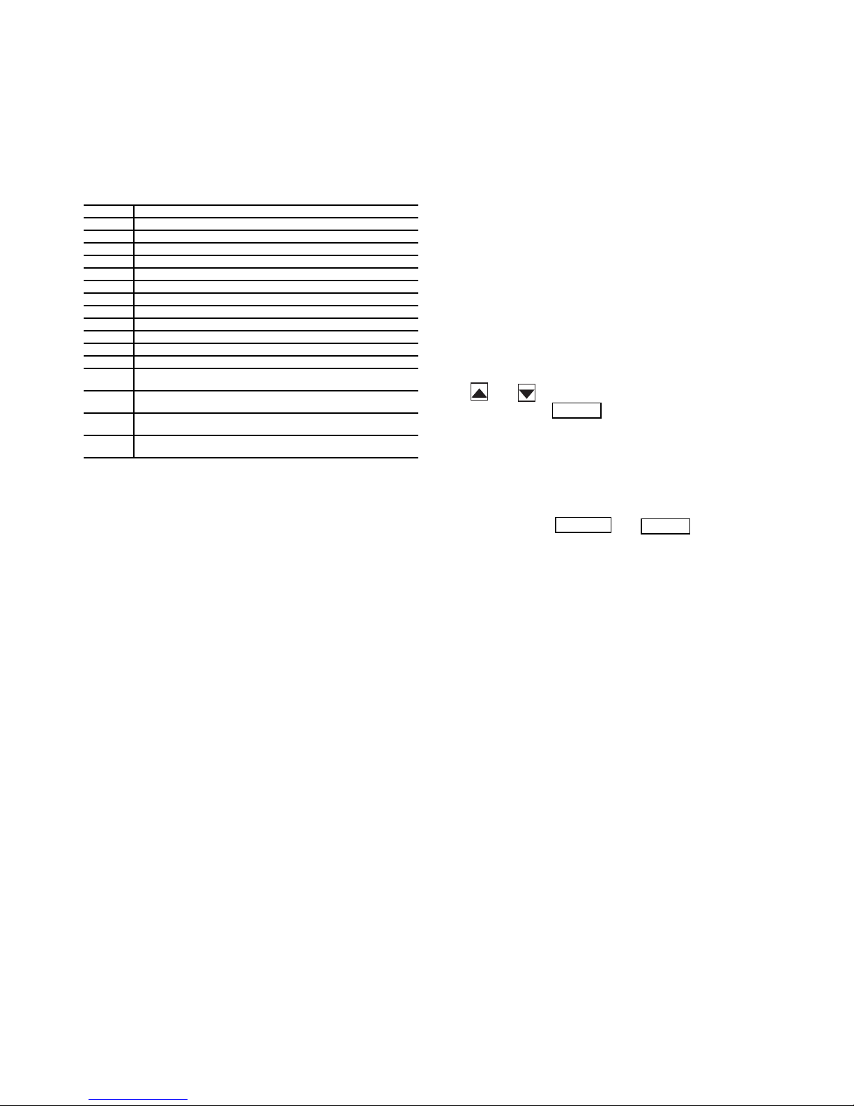
Scrolling Marquee — This device is the standard inter-
face used to access the control information, read sensor values,
and test the unit. The scrolling marquee is located in the main
control box. The scrolling marquee display is a 4-key, 4-character LED (light-emitting diode) display module. The display
also contains an Alarm Status LED. See Fig. 1. The display is
easy to operate using 4 buttons and a group of 11 LEDs that indicate the following menu structures, referred to as modes (see
Appendix A):
• Run Status
• Service Test
• Temperatures
•Pressures
• Set points
• Inputs
• Outputs
• Configuration
• Timeclock
• Operating Modes
•Alarms
Through the scrolling marquee, the user can access all of the
inputs and outputs to check on their values and status, configure operating parameters plus evaluate the current decision status for operating modes. Because the A Series units are
equipped with suction pressure and saturated condensing
temperature transducers, the scrolling marquee can also display
refrigerant circuit pressures typically obtained from service
gages. The control also includes an alarm history which can be
accessed from the display. In addition, through the scrolling
marquee, the user can access a built-in test routine that can be
used at start-up commissioning to diagnose operational problems with the unit.
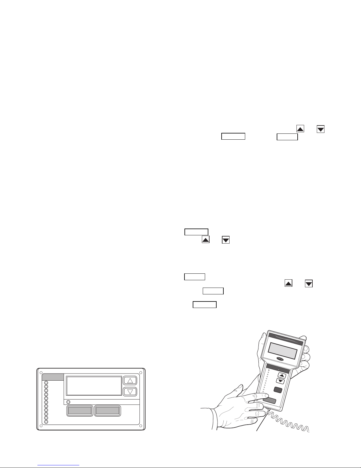
Accessory Navigator™ Display — The accessory
hand-held Navigator display can be used with the A Series
units. See Fig. 2. The Navigator display operates the same way
as the scrolling marquee device. The Navigator display is
plugged into the RJ-14 (LEN) jack in the main control box on
the COMM board. The Navigator display can also be plugged
into the RJ-14 jack located on the ECB (economizer control
board) located in the auxiliary control box.
Operation — All units are shipped from the factory with
the scrolling marquee display, which is located in the main control box. See Fig. 1. In addition, the ComfortLink™ controls
also support the use of the handheld Navigator display.
Both displays provide the user with an interface to the
ComfortLink control system. The displays have and
arrow keys, an key and an key. These
keys are used to navigate through the different modes of the
display structure. The Navigator and the scrolling marquee displays operate in the same manner, except that the Navigator
display has multiple lines of display and the scrolling marquee
has a single line. All further discussions and examples in this
document will be based on the scrolling marquee display. See
Table 2 for the menu structure.
The four keys are used to navigate through the display
structure, which is organized in a tiered mode structure. If the
buttons have not been used for a period, the display will default
to the AUTO VIEW display category as shown under the RUN
STATUS category. To show the top-level display, press the
key until a blank display is shown. Then
use the and arrow keys to scroll through the top-level
categories (modes). These are listed in Appendix A and will be
indicated on the scrolling marquee by the LED next to each
mode listed on the face of the display.
When a specific mode or sub-mode is located, push the
key to enter the mode. Depending on the mode, there
may be additional tiers. Continue to use the and keys
and the keys until the desired display item is found.
At any time, the user can move back a mode level by pressing
the key. Once an item has been selected the display
will flash showing the item, followed by the item value and
then followed by the item units (if any).
4
ENTER
ESCAPE
ENTER
ESCAPE
ENTER
ENTER
ENTER
ENTER
ESCAPE
ENTER
SCROLL
+
-
NAVIGATE/
EXIT
MODIFY/
SELECT
PAGE
Fig. 3 — System Pilot™ User Interface
A33-1050
Items in the Configuration and Service Test modes are
password protected. The display will flash PASS and WORD
when required. Use the and arrow keys to enter the
four digits of the password. The default password is 1111.
Pressing the and keys simultaneously
will scroll an expanded text description across the display indicating the full meaning of each display point. Pressing the
and keys when the display is blank
(MODE LED level) will return the display to its default menu
of rotating AUTO VIEW display items. In addition, the password will need to be entered again before changes can be made.
Changing item values or testing outputs is accomplished in
the same manner. Locate and display the desired item. If the
display is in rotating auto-view, press the key to stop
the display at the desired item. Press the key again so
that the item value flashes. Use the arrow keys to change the
value of state of an item and press the key to accept
it. Press the key and the item, value or units display
will resume. Repeat the process as required for other items.
If the user needs to force a variable, follow the same process
as when editing a configuration parameter. A forced variable
will be displayed with a blinking “f” following its value. For
example, if supply fan requested (FA N. F) is forced, the display
shows “YESf”, where the “f” is blinking to signify a force on
the point. Remove the force by selecting the point that is forced
with the key and then pressing the and arrow keys simultaneously.
Depending on the unit model, factory-installed options and
field-installed accessories, some of the items in the various
Mode categories may not apply.
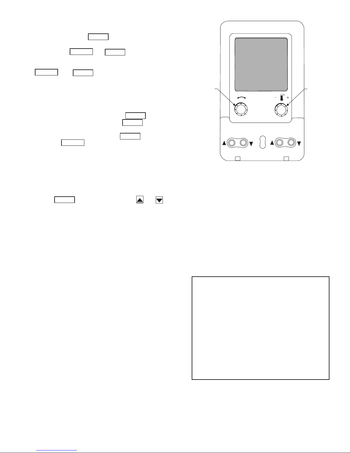
System Pilot™ Interface — The System Pilot
(33PILOT-01) device is a component of Carrier’s 3V™ system
and serves as a user-interface and configuration tool for all Carrier communicating devices. The System Pilot device can be
used to install and commission a 3V zoning system, linkage
compatible air source, universal controller, and all other devices operating on the CCN system.
Additionally, the System Pilot device can serve as a
wall-mounted temperature sensor for space temperature
measurement. The occupant can use the System Pilot device to
change set points. A security feature is provided to limit access
of features for unauthorized users. See Fig. 3 for System Pilot
details.
CCN Tables and Display — In addition to the unit-
mounted scrolling marquee display, the user can also access the
same information through the CCN tables by using the Service
Tool or other CCN programs. Details on the CCN tables are
summarized in Appendix B. The variable names used for the
CCN tables and the scrolling marquee tables may be different
and more items are displayed in the CCN tables. As a reference, the CCN variable names are included in the scrolling
marquee tables and the scrolling marquee names are included
in the local display tables in Appendix B.
GENERICS STATUS DISPLAY TABLE — The GENERICS
points table allows the service/installer the ability to create a
custom table in which up to 20 points from the 5 CCN
categories (Points, Config, Service-Config, Set Point, and
Maintenance) may be collected and displayed.
In the Service-Config table section, there is a table named
“generics”. This table contains placeholders for up to 20 CCN
point names and allows the user to decide which points are displayed in the GENERICS points table under the local display.
Each one of these placeholders allows the input of an 8-character
ASCII string. Using a CCN interface, enter the Edit mode for the
Service-Config table “generics” and enter the CCN name for
each point to be displayed in the custom points table in the order
they will be displayed. When done entering point names, download the table to the rooftop unit control.
IMPORTANT: The computer system software
(ComfortVIEW™, Service Tool, etc.) that is used to
interact with CCN controls always saves a template of
items it considers as static (e.g., limits, units, forcibil-
ity, 24-character text strings, and point names) after
the software uploads the tables from a control. There-
after, the software is only concerned with run time
data like value and hardware/force status. With this in
mind, it is important that anytime a change is made to
the Service-Config table “generics” (which in turn
changes the points contained in the GENERICS point
table), that a complete new upload be performed. This
requires that any previous table database be
completely removed first. Failure to do this will not
allow the user to display the new points that have been
created and the CCN interface will have a different
table database than the unit control.
5

RUN
STATUS
Auto View of
Run Status
(VIEW)
Econ
Run Status
(ECON)
Cooling
Information
(COOL)
Mode
Trip Helper
(TRIP)
CCN
Linkage
(LINK)
Compressor
Run Hours
(HRS)
Compressor
Starts
(STRT)
Timeguards
(TMGD)
Software
Ver sio n
Numbers
(VERS)
SERVICE
TEST
Service Test Mode
(TEST)
Software
Command
Disable
(STOP)
Soft Stop
Request
(S.STP)
Supply Fan
Request
(FAN.F)
4 in. Filter
Change Mode
(F.4.CH)
Test Independent
Outputs
(INDP)
Te st F an s
(FANS)
Test Cooling
(COOL)
Test Heating
(HEAT)
Table 2 — Scrolling Marquee Menu Display Structure
(ComfortLink™ Display Modes)
TEMPERATURES PRESSURES SETPOINTS INPUTS OUTPUTS CONFIGURATION
Air
Temperatures
(AIR.T)
Refrigerant
Temperatures
(REF.T)
Air Pressures
(AIR.P)
Refrigerant
Pressures
(REF.P)
Occupied Heat
Setpoint
(OHSP)
Occupied Cool
Setpoint
(OCSP)
Unoccupied
Heat Setpoint
(UHSP)
Unoccupied
Cool Setpoint
(UCSP)
Heat - Cool
Setpoint
(GAP)
VAV O cc
Cool On
(V.C.ON)
VAV O cc
Cool Off
(V.C.OF)
Supply Air
Setpoint
(SASP)
Supply Air
Setpoint Hi
(SA.HI)
General Inputs
(GEN.I)
Compressor
Feedback
(FD.BK)
Thermostat
Inputs
(STAT)
Fire-Smoke
Modes
(FIRE)
Relative
Humidity
(REL.H)
Air Quality
Sensors
(AIR.Q)
Reset Inputs
(RSET)
4-20 Milliamp
Inputs
(4-20)
Fans
(FANS)
Cooling
(COOL)
Heating
(HEAT)
Economizer
(ECON)
General
Outputs
(GEN.O)
Unit
Configuration
(UNIT)
Cooling
Configuration
(COOL)
Evap/Discharge
Temp. Reset
(EDT.R)
Heating
Configuration
(HEAT)
Supply Static
Press. Config.
(SP)
Economizer
Configuration
(ECON)
Building Press.
Configs
(BP)
Cool/Heat
Setpt. Offsets
(D.LV.T)
Demand Limit
Config.
(DMD.L)
TIME
CLOCK
Time of Day
(TIME)
Month, Date,
Day and Year
(DATE)
Local Time
Schedule
(SCH.L)
Local
Holiday
Schedules
(HOL.L)
Daylight
Savings
Time
(DAY.S)
OPERATING
MODES
System
Mode
(SYS.M)
HVAC Mode
(HVAC)
Control Type
(CTRL)
Mode
Controlling
Unit
(MODE)
ALARMS
Currently
Active
Alarms
(CURR)
Reset All
Current
Alarms
(R.CUR)
Alarm
History
(HIST)
Supply Air
Setpoint Lo
(SA.LO)
Heating Supply
Air Setpoint
(SA.HT)
Te mp e r i ng
Purge SASP
(T.PRG)
Tempering in
Cool SASP
(T.CL)
Tempering in
Vent Occ SASP
(T.V.OC)
Tempering in
Vent Unocc.
SASP
(T.V.UN)
Indoor Air
Quality Cfg.
(IAQ)
Dehumidification
Config.
(DEHU)
CCN
Configuration
(CCN)
Alert Limit
Config.
(ALLM)
Sensor Trim
Config.
(TRIM)
Switch
Logic
(SW.LG)
Display
Configuration
(DISP)
6

START-UP
Controls — Use the following steps for the controls:
IMPORTANT: Do not attempt to start unit, even
momentarily, until all items on the Start-Up Checklist
and the following steps have been completed.
Unit Preparation —
accordance with the installation instructions and applicable
codes.
Check that unit has been installed in
Unit Setup — Make sure that the economizer hoods have
been installed and that the outdoor filters are properly installed.
Internal Wiring — Ensure that all electrical connections
in the control box are tightened as required. If the unit has
staged gas heat make sure that the leaving air temperature
(LAT) sensors have been routed to the supply ducts as required.
Accessory Installation — Check to make sure that all
accessories including space thermostats and sensors have been
installed and wired as required by the instructions and unit
wiring diagrams.
Crankcase Heaters — Crankcase heaters are energized
as long as there is power to the unit, except when the compressors are running.
IMPORTANT: Unit power must be on for 24 hrs prior
to start-up of compressors. Otherwise damage to compressors may result.
Evaporator Fan — Fan belt and fixed pulleys are factory-
installed. See Tables 3-38 for fan performance. Remove tape
from fan pulley, and be sure that fans rotate in the proper direction. See Table 39 for motor limitations. See Tables 40A and
40B for air quantity limits. Static pressure drop for power
exhaust is negligible. To alter fan performance, see Evaporator
Fan Performance Adjustment section on page 130.
IMPORTANT: The unit is shipped with the unit control
disabled. To enable the control, set Local Machine Disable
(Service Test
1. Set any control configurations that are required (fieldinstalled accessories, etc.). The unit is factory configured
for all appropriate factory-installed options.
2. Enter unit set points. The unit is shipped with the set point
default values. If a different set point is required use the
scrolling marquee, Navigator™ accessory or Service
Tool software to change the configuration valves.
3. If the internal unit schedules are going to be used configure the Occupancy schedule.
4. Verify that the control time periods programmed meet
current requirements.
5. Using Service Test mode, verify operation of all major
components.
6. If the unit is a VAV unit make sure to configure the VFD
static pressure set point using the display. To checkout the
VFD use the VFD instructions shipped with the unit.
STOP) to No.
Gas Heat — Verify gas pressure before turning on gas heat
as follows:
1. Turn off field-supplied manual gas stop, located external
to the unit.
2. Connect pressure gages to supply gas tap, located at fieldsupplied manual shutoff valves.
3. Connect pressure gages to manifold pressure tap on unit
gas valve.
4. Supply gas pressure must not exceed 13.5 in. wg. Check
pressure at field-supplied shut-off valve.
5. Turn on manual gas stop and initiate a heating demand.
Jumper R to W1 in the control box to initiate heat.
6. Use the Service Test procedure to verify heat operation.
7. After the unit has run for several minutes, verify that
incoming pressure is 6.0 in. wg or greater and that the
manifold pressure is 3.5 in wg. If manifold pressure must
be adjusted refer to Gas Valve Adjustment section.
7
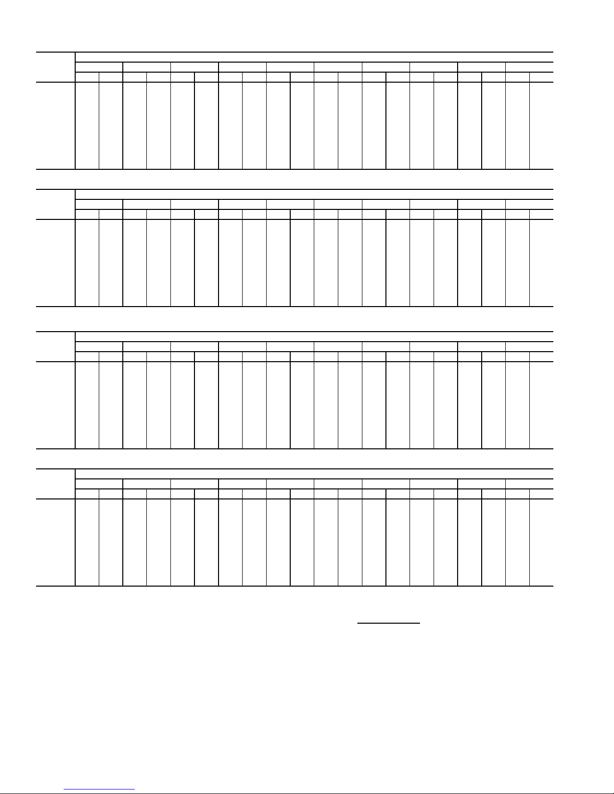
Table 3 — Fan Performance — 48AJ,AK020,025 and 48A2,A3020 Units
AIRFLOW
(CFM)
4,000 328 0.62 406 0.84 472 1.07 529 1.30 580 1.54 626 1.78 668 2.02 708 2.27 745 2.51 780 2.76
5,000 369 0.97 439 1.19 500 1.43 554 1.69 604 1.95 650 2.21 692 2.48 731 2.74 769 3.01 804 3.28
6,000 415 1.43 477 1.65 533 1.90 584 2.17 631 2.45 676 2.73 717 3.01 756 3.30 793 3.59 828 3.88
7,000 463 2.01 519 2.25 570 2.50 618 2.78 662 3.06 704 3.36 744 3.65 782 3.96 818 4.27 852 4.58
7,500 488 2.36 541 2.60 590 2.86 636 3.13 679 3.42 720 3.72 759 4.02 796 4.33 832 4.65 866 4.96
8,000 513 2.74 564 2.98 611 3.24 655 3.52 697 3.81 737 4.11 775 4.42 811 4.74 846 5.06 879 5.38
9,000 564 3.61 612 3.87 655 4.13 696 4.42 735 4.71 772 5.02 808 5.33 843 5.65 876 5.98 909 6.32
10,000 616 4.64 661 4.91 701 5.18 739 5.47 776 5.77 811 6.08 845 6.40 878 6.72 909 7.06 940 7.40
11,000 669 5.84 711 6.11 749 6.40 785 6.69 819 6.99 852 7.30 884 7.63 915 7.96 945 8.30 975 8.65
12,000 723 7.20 762 7.49 798 7.78 831 8.08 864 8.39 895 8.71 925 9.04 955 9.37 984 9.72 1012 10.07
12,500 750 7.95 788 8.25 823 8.54 855 8.85 887 9.16 917 9.48 947 9.81 976 10.15 1004 10.49 1031 10.84
13,000 777 8.75 814 9.05 848 9.35 880 9.66 910 9.97 940 10.30 969 10.63 997 10.97 1024 11.31 1051 11.67
0.2 0.4 0.6 0.8 1.0 1.2 1.4 1.6 1.8 2.0
Rpm Bhp Rpm Bhp Rpm Bhp Rpm Bhp Rpm Bhp Rpm Bhp Rpm Bhp Rpm Bhp Rpm Bhp Rpm Bhp
AVAILABLE EXTERNAL STATIC PRESSURE (in. wg)
AIRFLOW
(CFM)
4,000 814 3.01 845 3.26 876 3.51 905 3.76 934 4.02 961 4.28 987 4.54 1013 4.80 1038 5.06 1062 5.32
5,000 837 3.55 869 3.82 900 4.10 929 4.37 958 4.64 985 4.92 1012 5.20 1038 5.48 1063 5.76 1087 6.04
6,000 861 4.17 893 4.46 923 4.76 953 5.05 981 5.35 1009 5.65 1036 5.94 1062 6.24 1087 6.54 1111 6.84
7,000 885 4.89 917 5.20 947 5.51 977 5.83 1005 6.14 1033 6.46 1059 6.78 1085 7.09 1110 7.41 1135 7.73
7,500 898 5.28 930 5.61 960 5.93 989 6.25 1017 6.58 1045 6.90 1071 7.23 1097 7.56 1122 7.88 1147 8.21
8,000 912 5.71 943 6.04 973 6.37 1002 6.70 1030 7.04 1057 7.37 1083 7.71 1109 8.04 1134 8.38 1159 8.72
9,000 940 6.66 970 7.00 999 7.35 1028 7.69 1055 8.04 1082 8.39 1109 8.75 1134 9.10 1159 9.45 1183 9.81
10,000 971 7.75 1000 8.10 1028 8.46 1056 8.82 1083 9.18 1109 9.54 1135 9.91 1160 10.28 1185 10.65 — —
11,000 1004 9.00 1032 9.36 1059 9.73 1086 10.09 1112 10.46 1138 10.84 1163 11.22 1188 11.60 — — — —
12,000 1039 10.42 1066 10.79 1093 11.16 1119 11.53 1144 11.91 1169 12.30 1193 12.68 — — — — — —
12,500 1058 11.20 1085 11.57 1110 11.94 1136 12.32 1161 12.70 1185 13.09 — — — — — — — —
13,000 1077 12.03 1103 12.40 1129 12.77 1154 13.15 1178 13.54 — — — — — — — — — —
2.2 2.4 2.6 2.8 3.0 3.2 3.4 3.6 3.8 4.0
Rpm Bhp Rpm Bhp Rpm Bhp Rpm Bhp Rpm Bhp Rpm Bhp Rpm Bhp Rpm Bhp Rpm Bhp Rpm Bhp
AVAILABLE EXTERNAL STATIC PRESSURE (in. wg)
Table 4 — Fan Performance — 48AJ,AK027,030 and 48A2,A3025-030 Units
AIRFLOW
(CFM)
4,000 331 0.63 408 0.85 474 1.08 531 1.31 581 1.55 627 1.79 670 2.03 709 2.28 746 2.52 781 2.77
5,000 374 0.98 443 1.20 503 1.45 558 1.70 607 1.96 653 2.23 695 2.49 734 2.76 771 3.03 806 3.30
6,000 421 1.45 482 1.68 538 1.93 589 2.20 636 2.47 680 2.75 721 3.04 759 3.33 796 3.62 831 3.91
7,000 471 2.04 526 2.28 576 2.54 623 2.81 668 3.10 710 3.39 749 3.69 787 4.00 823 4.31 857 4.62
8,000 522 2.78 572 3.03 619 3.29 662 3.57 704 3.86 743 4.16 781 4.47 817 4.79 851 5.11 885 5.44
9,000 574 3.66 621 3.92 664 4.19 704 4.47 743 4.77 780 5.08 815 5.40 850 5.72 883 6.05 915 6.39
10,000 628 4.71 671 4.97 711 5.25 748 5.54 784 5.84 819 6.15 853 6.47 885 6.81 917 7.14 948 7.49
11,000 682 5.91 722 6.19 759 6.48 795 6.77 828 7.08 861 7.40 893 7.72 924 8.06 954 8.40 983 8.75
12,000 736 7.30 774 7.59 809 7.88 842 8.18 874 8.49 905 8.82 935 9.15 965 9.48 993 9.83 1021 10.19
13,000 791 8.86 827 9.16 860 9.46 891 9.78 922 10.09 951 10.42 979 10.75 1007 11.10 1034 11.45 1061 11.80
14,000 846 10.61 880 10.93 912 11.24 941 11.56 970 11.88 998 12.21 1025 12.56 1052 12.90 1078 13.26 1103 13.62
15,000 902 12.56 934 12.89 964 13.21 992 13.54 1020 13.87 1046 14.21 1072 14.55 1098 14.91 1122 15.26 1147 15.63
AIRFLOW
(CFM)
4,000 815 3.02 847 3.27 877 3.52 906 3.77 935 4.03 962 4.29 988 4.55 1014 4.81 1039 5.07 1063 5.33
5,000 839 3.57 871 3.84 902 4.11 931 4.39 960 4.66 987 4.94 1014 5.22 1039 5.50 1064 5.78 1089 6.06
6,000 864 4.20 896 4.49 926 4.79 956 5.08 984 5.38 1012 5.68 1038 5.97 1064 6.27 1089 6.57 1114 6.87
7,000 890 4.93 921 5.24 951 5.55 980 5.87 1009 6.18 1036 6.50 1063 6.82 1088 7.14 1114 7.45 1138 7.77
8,000 917 5.76 948 6.09 977 6.42 1006 6.76 1034 7.09 1061 7.43 1088 7.76 1113 8.10 1138 8.43 1163 8.77
9,000 946 6.73 976 7.07 1005 7.42 1033 7.76 1061 8.11 1088 8.46 1114 8.82 1139 9.17 1164 9.52 1188 9.88
10,000 978 7.84 1007 8.19 1035 8.55 1063 8.91 1089 9.27 1116 9.63 1141 10.00 1166 10.37 1191 10.74 — —
11,000 1012 9.10 1040 9.47 1067 9.83 1094 10.20 1120 10.57 1145 10.95 1170 11.33 1195 11.71 — — — —
12,000 1048 10.54 1075 10.91 1102 11.28 1127 11.66 1152 12.04 1177 12.42 — — — — — — — —
13,000 1087 12.17 1113 12.54 1138 12.91 1163 13.30 1187 13.68 — — — — — — — — — —
14,000 1128 13.98 1153 14.36 1177 14.74 — — ————————————
15,000 117116.00119416.38————————————————
LEGEND
Bhp — Brake Horsepower
edb — Entering Dry Bulb
ewb — Entering Wet Bulb
NOTES:
1. Fan performance is based on wet coils, economizer, roof curb, cabinet
losses, and clean 2-in. filters.
0.2 0.4 0.6 0.8 1.0 1.2 1.4 1.6 1.8 2.0
Rpm Bhp Rpm Bhp Rpm Bhp Rpm Bhp Rpm Bhp Rpm Bhp Rpm Bhp Rpm Bhp Rpm Bhp Rpm Bhp
2.2 2.4 2.6 2.8 3.0 3.2 3.4 3.6 3.8 4.0
Rpm Bhp Rpm Bhp Rpm Bhp Rpm Bhp Rpm Bhp Rpm Bhp Rpm Bhp Rpm Bhp Rpm Bhp Rpm Bhp
AVAILABLE EXTERNAL STATIC PRESSURE (in. wg)
AVAILABLE EXTERNAL STATIC PRESSURE (in. wg)
2. Conversion — Bhp to watts:
Watts =
3. Variable air volume units will operate down to 70 cfm/ton. Performance at
70 cfm/ton is limited to unloaded operation and may be additionally limited
by edb and ewb conditions.
Bhp x 746
Motor efficiency
8
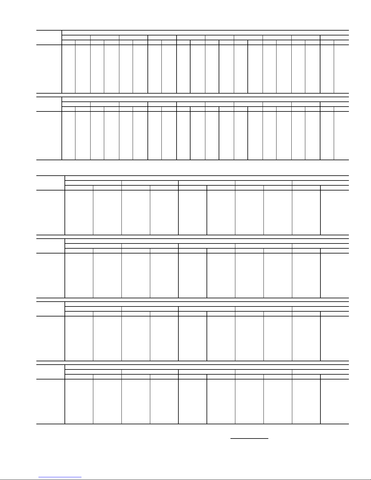
Table 5 — Fan Performance — 48AJ,AK,A2,A3035 Units
AIRFLOW
(Cfm)
7,000 534 2.46 584 2.80 630 3.13 674 3.48 716 3.82 756 4.16 793 4.50 829 4.83 863 5.17 896 5.49
8,000 590 3.27 635 3.63 677 3.99 718 4.35 757 4.72 794 5.08 830 5.45 864 5.81 897 6.18 929 6.54
9,000 646 4.23 687 4.62 726 5.00 764 5.38 800 5.76 835 6.15 869 6.54 902 6.93 934 7.31 964 7.70
10,000 704 5.35 742 5.77 778 6.17 812 6.57 846 6.97 879 7.38 911 7.78 942 8.19 972 8.60 1002 9.01
10,500 733 5.97 769 6.40 804 6.82 837 7.23 870 7.64 902 8.05 933 8.46 963 8.88 992 9.30 1021 9.72
11,000 762 6.63 797 7.08 830 7.51 863 7.93 894 8.35 925 8.77 955 9.19 984 9.62 1013 10.04 1041 10.47
12,000 820 8.09 853 8.56 884 9.01 915 9.46 944 9.90 973 10.34 1001 10.78 1029 11.22 1056 11.66 1083 12.10
13,000 879 9.72 909 10.22 939 10.70 968 11.17 996 11.63 1023 12.09 1050 12.55 1076 13.01 1102 13.46 1127 13.92
14,000 938 11.54 967 12.07 995 12.58 1022 13.07 1048 13.55 1074 14.03 1099 14.51 1124 14.98 1149 15.46 1173 15.93
15,000 997 13.56 1024 14.11 1051 14.64 1076 15.16 1102 15.67 1126 16.17 1150 16.66 1174 17.16 1197 17.65 1220 18.14
16,000 1056 15.78 1082 16.35 1107 16.91 1132 17.45 1156 17.98 1179 18.50 1202 19.02 1225 19.53 1247 20.04 1269 20.55
17,000 1116 18.20 1140 18.80 1164 19.38 1188 19.95 1210 20.50 1233 21.05 1255 21.58 1276 22.11 1298 22.64 — —
17,500 114519.49117020.10119320.70121621.28123821.84126022.40128222.94——————
AIRFLOW
(Cfm)
7,000 927 5.81 956 6.13 985 6.45 1012 6.76 1039 7.06 1065 7.37 1090 7.67 1114 7.97 1138 8.26 1161 8.56
8,000 960 6.89 989 7.25 1018 7.60 1045 7.94 1072 8.29 1098 8.63 1122 8.96 1147 9.29 1170 9.62 1193 9.95
9,000 994 8.09 1023 8.47 1051 8.85 1078 9.23 1104 9.61 1130 9.98 1155 10.35 1179 10.71 1203 11.08 1226 11.44
10,000 1030 9.42 1058 9.82 1085 10.23 1112 10.64 1138 11.04 1163 11.44 1188 11.84 1212 12.24 1235 12.64 1258 13.03
10,500 1049 10.14 1077 10.56 1103 10.97 1129 11.39 1155 11.81 1180 12.23 1204 12.64 1228 13.05 1251 13.46 1274 13.87
11,000 1069 10.90 1095 11.33 1122 11.76 1147 12.18 1173 12.61 1197 13.04 1221 13.47 1245 13.89 1268 14.31 1291 14.73
12,000 110912.55113513.00116013.44118513.89120914.34123314.79125615.24127915.69————
13,000 115214.38117614.84120015.31122415.77124816.24127116.70129317.17——————
14,000 119616.41122016.88124317.36126617.84128818.32——————————
15,000 124318.63126519.12128719.61——————————————
16,000 129021.06——————————————————
17,000 ————————————————————
17,500 ————————————————————
0.20.40.60.81.01.21.41.61.82.0
Rpm Bhp Rpm Bhp Rpm Bhp Rpm Bhp Rpm Bhp Rpm Bhp Rpm Bhp Rpm Bhp Rpm Bhp Rpm Bhp
2.22.42.62.83.03.23.43.63.84.0
Rpm Bhp Rpm Bhp Rpm Bhp Rpm Bhp Rpm Bhp Rpm Bhp Rpm Bhp Rpm Bhp Rpm Bhp Rpm Bhp
AVAILABLE EXTERNAL STATIC PRESSURE (in. wg)
AVAILABLE EXTERNAL STATIC PRESSURE (in. wg)
Table 6 — Fan Performance — 48AJ,AK036 Units
AIRFLOW
(Cfm)
7,000 454 2.15 508 2.52 557 2.90 605 3.29 650 3.69
8,000 502 2.90 550 3.30 596 3.71 639 4.12 680 4.54
9,000 552 3.81 595 4.24 637 4.67 677 5.11 715 5.55
10,000 602 4.89 642 5.34 680 5.80 717 6.26 752 6.73
11,000 653 6.15 689 6.62 725 7.11 759 7.59 792 8.08
12,000 704 7.60 738 8.09 771 8.60 803 9.11 834 9.63
13,000 756 9.24 788 9.76 818 10.29 848 10.83 878 11.36
14,000 808 11.10 838 11.64 867 12.19 895 12.74 922 13.30
15,000 861 13.18 888 13.74 915 14.31 942 14.88 968 15.46
16,000 914 15.49 940 16.06 965 16.65 990 17.24 1015 17.85
17,000 967 18.03 991 18.62 1015 19.23 1039 19.85 1062 20.47
17,500 993 19.40 1017 20.00 1040 20.61 1064 21.24 1086 21.87
AIRFLOW
(Cfm)
7,000 693 4.09 734 4.52 773 4.95 811 5.39 847 5.83
8,000 720 4.97 759 5.40 796 5.85 832 6.31 867 6.77
9,000 752 6.00 788 6.45 823 6.92 857 7.39 890 7.87
10,000 787 7.20 821 7.67 854 8.16 886 8.64 917 9.14
11,000 825 8.58 856 9.07 887 9.57 918 10.08 947 10.59
12,000 865 10.14 895 10.66 924 11.18 952 11.71 980 12.24
13,000 906 11.90 935 12.44 962 12.99 989 13.53 1016 14.08
14,000 950 13.87 976 14.43 1002 15.00 1028 15.57 1053 16.14
15,000 994 16.05 1019 16.63 1044 17.22 1068 17.81 1093 18.40
16,000 1039 18.45 1063 19.06 1087 19.67 1110 20.28 1133 20.89
17,000 1086 21.09 1109 21.72 1131 22.35 1153 22.98 1175 23.61
17,500 1109 22.50 1131 23.14 1154 23.78 1175 24.42 1197 25.07
AIRFLOW
(Cfm)
7,000 881 6.29 914 6.74 946 7.21 977 7.68 1006 8.15
8,000 901 7.24 933 7.72 965 8.20 995 8.69 1024 9.19
9,000 923 8.35 954 8.85 985 9.35 1014 9.86 1043 10.37
10,000 948 9.64 978 10.15 1007 10.66 1036 11.19 1064 11.71
11,000 976 11.11 1005 11.63 1033 12.16 1061 12.70 1088 13.24
12,000 1008 12.77 1035 13.31 1062 13.86 1088 14.41 1114 14.97
13,000 1042 14.64 1068 15.19 1093 15.76 1118 16.32 1143 16.89
14,000 1078 16.71 1103 17.28 1127 17.86 1151 18.45 1174 19.03
15,000 1116 19.00 1140 19.59 1163 20.19 1186 20.79 1208 21.40
16,000 1156 21.51 1178 22.12 1200 22.74 1222 23.36 1244 23.98
17,000 1197 24.25 1218 24.89 1240 25.52 1261 26.17 1281 26.81
17,500 1218 25.71 1239 26.36 1260 27.00 1280 27.66 — —
AIRFLOW
(Cfm)
7,000 1035 8.63 1062 9.11 1089 9.60 1115 10.09 1140 10.58
8,000 1053 9.69 1081 10.19 1108 10.70 1134 11.21 1159 11.73
9,000 1072 10.89 1099 11.41 1126 11.94 1152 12.47 1177 13.00
10,000 1092 12.25 1119 12.78 1145 13.33 1171 13.88 1196 14.43
11,000 1114 13.79 1140 14.34 1166 14.90 1191 15.46 1216 16.03
12,000 1139 15.53 1164 16.09 1189 16.67 1213 17.24 1237 17.83
13,000 1167 17.47 1191 18.05 1215 18.64 1238 19.23 1262 19.82
14,000 1198 19.63 1221 20.22 1244 20.82 1266 21.43 1288 22.04
15,000 1230 22.00 1253 22.62 1274 23.23 1296 23.85 — —
16,000 126524.61128625.24——————
17,000 ——————————
17,500 ——————————
LEGEND
Bhp — Brake Horsepower
edb — Entering Dry Bulb
ewb — Entering Wet Bulb
NOTES:
1. Fan performance is based on wet coils, economizer, roof curb, cabinet losses, and clean
2-in. filters.
0.2 0.4 0.6 0.8 1.0
Rpm Bhp Rpm Bhp Rpm Bhp Rpm Bhp Rpm Bhp
1.2 1.4 1.6 1.8 2.0
Rpm Bhp Rpm Bhp Rpm Bhp Rpm Bhp Rpm Bhp
2.2 2.4 2.6 2.8 3.0
Rpm Bhp Rpm Bhp Rpm Bhp Rpm Bhp Rpm Bhp
3.2 3.4 3.6 3.8 4.0
Rpm Bhp Rpm Bhp Rpm Bhp Rpm Bhp Rpm Bhp
AVAILABLE EXTERNAL STATIC PRESSURE (in. wg)
AVAILABLE EXTERNAL STATIC PRESSURE (in. wg)
AVAILABLE EXTERNAL STATIC PRESSURE (in. wg)
AVAILABLE EXTERNAL STATIC PRESSURE (in. wg)
2. Conversion — Bhp to watts:
Watts =
3. Var iable air volume units will operate down to 70 cfm/ton. Performance at 70 cfm/ton is
limited to unloaded operation and may be additionally limited by edb and ewb conditions.
Bhp x 746
Motor efficiency
9
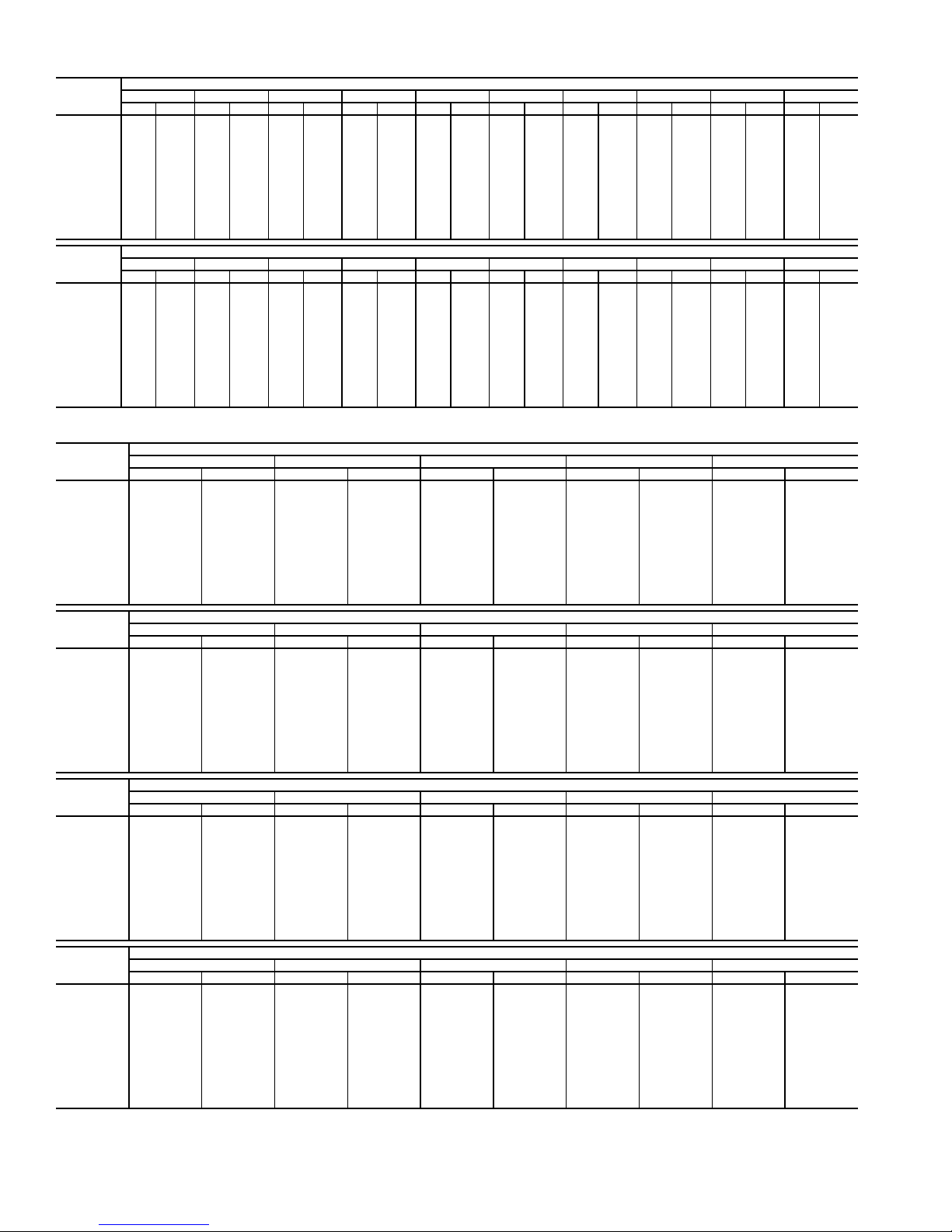
Table 7 — Fan Performance — 48AJ,AK,A2,A3040 Units
AIRFLOW
(Cfm)
8,000 502 2.90 550 3.30 596 3.71 639 4.12 680 4.54 720 4.97 759 5.40 796 5.85 832 6.31 867 6.77
9,000 552 3.81 595 4.24 637 4.67 677 5.11 715 5.55 752 6.00 788 6.45 823 6.92 857 7.39 890 7.87
10,000 602 4.89 642 5.34 680 5.80 717 6.26 752 6.73 787 7.20 821 7.67 854 8.16 886 8.64 917 9.14
11,000 653 6.15 689 6.62 725 7.11 759 7.59 792 8.08 825 8.58 856 9.07 887 9.57 918 10.08 947 10.59
12,000 704 7.60 738 8.09 771 8.60 803 9.11 834 9.63 865 10.14 895 10.66 924 11.18 952 11.71 980 12.24
13,000 756 9.24 788 9.76 818 10.29 848 10.83 878 11.36 906 1 1.90 935 12.44 962 12.99 989 13.53 1016 14.08
14,000 808 11.10 838 11.64 867 12.19 895 12.74 922 13.30 950 13.87 976 14.43 1002 15.00 1028 15.57 1053 16.14
15,000 861 13.18 888 13.74 915 14.31 942 14.88 968 15.46 994 16.05 1019 16.63 1044 17.22 1068 17.81 1093 18.40
16,000 914 15.49 940 16.06 965 16.65 990 17.24 1015 17.85 1039 18.45 1063 19.06 1087 19.67 1110 20.28 1133 20.89
17,000 967 18.03 991 18.62 1015 19.23 1039 19.85 1062 20.47 1086 21.09 1109 21.72 1131 22.35 1153 22.98 1175 23.61
18,000 1020 20.82 1043 21.43 1066 22.06 1088 22.69 1111 23.33 1133 23.97 1155 24.62 1176 25.27 1197 25.92 1219 26.58
19,000 1073 23.87 1095 24.50 1117 25.14 1138 25.79 1159 26.44 1180 27.11 1201 27.77 1222 28.45 1242 29.12 — —
20,000 112727.18114727.82116828.48118829.15————————————
AIRFLOW
(Cfm)
8,000 901 7.24 933 7.72 965 8.20 995 8.69 1024 9.19 1053 9.69 1081 10.19 1108 10.70 1134 11.21 1159 11.73
9,000 923 8.35 954 8.85 985 9.35 1014 9.86 1043 10.37 1072 10.89 1099 11.41 1126 11.94 1 152 12.47 1177 13.00
10,000 948 9.64 978 10.15 1007 10.66 1036 11.19 1064 11.71 1092 12.25 1119 12.78 1145 13.33 1171 13.88 1196 14.43
11,000 976 11.11 1005 11.63 1033 12.16 1061 12.70 1088 13.24 1114 13.79 1140 14.34 1166 14.90 1191 15.46 1216 16.03
12,000 1008 12.77 1035 13.31 1062 13.86 1088 14.41 1114 14.97 1139 15.53 1164 16.09 1189 16.67 1213 17.24 1237 17.83
13,000 1042 14.64 1068 15.19 1093 15.76 1118 16.32 1143 16.89 1167 17.47 1191 18.05 1215 18.64 1238 19.23 1262 19.82
14,000 1078 16.71 1103 17.28 1127 17.86 1151 18.45 1174 19.03 1198 19.63 1221 20.22 1244 20.82 1266 21.43 1288 22.04
15,000 1116 19.00 1140 19.59 1163 20.19 1186 20.79 1208 21.40 1230 22.00 1253 22.62 1274 23.23 1296 23.85 — —
16,000 115621.51117822.12120022.74122223.36124423.98126524.61128625.24——————
17,000 119724.25121824.89124025.52126126.17128126.81——————————
18,000 123927.24126027.89128028.55——————————————
19,000 ————————————————————
20,000 ————————————————————
0.20.40.60.81.01.21.41.61.82.0
RpmBhpRpmBhpRpmBhpRpmBhpRpmBhpRpmBhpRpmBhpRpmBhpRpmBhpRpmBhp
2.22.42.62.83.03.23.43.63.84.0
RpmBhpRpmBhpRpmBhpRpmBhpRpmBhpRpmBhpRpmBhpRpmBhpRpmBhpRpmBhp
AVAILABLE EXTERNAL STATIC PRESSURE (in. wg)
AVAILABLE EXTERNAL STATIC PRESSURE (in. wg)
Table 8 — Fan Performance — 48AJ,AK041 Units
AIRFLOW
(Cfm)
8,000 502 2.90 550 3.30 596 3.71 639 4.12 680 4.54
9,000 552 3.81 595 4.24 637 4.67 677 5.11 715 5.55
10,000 602 4.89 642 5.34 680 5.80 717 6.26 752 6.73
11,000 653 6.15 689 6.62 725 7.11 759 7.59 792 8.08
12,000 704 7.60 738 8.09 771 8.60 803 9.11 834 9.63
13,000 756 9.24 788 9.76 818 10.29 848 10.83 878 11.36
14,000 808 11.10 838 11.64 867 12.19 895 12.74 922 13.30
15,000 861 13.18 888 13.74 915 14.31 942 14.88 968 15.46
16,000 914 15.49 940 16.06 965 16.65 990 17.24 1015 17.85
17,000 967 18.03 991 18.62 1015 19.23 1039 19.85 1062 20.47
18,000 1020 20.82 1043 21.43 1066 22.06 1088 22.69 1111 23.33
19,000 1073 23.87 1095 24.50 1117 25.14 1138 25.79 1159 26.44
20,000 1127 27.18 1147 27.82 1168 28.48 1188 29.15 — —
AIRFLOW
(Cfm)
8,000 720 4.97 759 5.40 796 5.85 832 6.31 867 6.77
9,000 752 6.00 788 6.45 823 6.92 857 7.39 890 7.87
10,000 787 7.20 821 7.67 854 8.16 886 8.64 917 9.14
11,000 825 8.58 856 9.07 887 9.57 918 10.08 947 10.59
12,000 865 10.14 895 10.66 924 11.18 952 11.71 980 12.24
13,000 906 11.90 935 12.44 962 12.99 989 13.53 1016 14.08
14,000 950 13.87 976 14.43 1002 15.00 1028 15.57 1053 16.14
15,000 994 16.05 1019 16.63 1044 17.22 1068 17.81 1093 18.40
16,000 1039 18.45 1063 19.06 1087 19.67 1110 20.28 1133 20.89
17,000 1086 21.09 1109 21.72 1131 22.35 1153 22.98 1175 23.61
18,000 1133 23.97 1155 24.62 1176 25.27 1197 25.92 1219 26.58
19,000 1180 27.11 1201 27.77 1222 28.45 1242 29.12 — —
20,000 ——————————
AIRFLOW
(Cfm)
8,000 901 7.24 933 7.72 965 8.20 995 8.69 1024 9.19
9,000 923 8.35 954 8.85 985 9.35 1014 9.86 1043 10.37
10,000 948 9.64 978 10.15 1007 10.66 1036 11.19 1064 11.71
11,000 976 11.11 1005 11.63 1033 12.16 1061 12.70 1088 13.24
12,000 1008 12.77 1035 13.31 1062 13.86 1088 14.41 1114 14.97
13,000 1042 14.64 1068 15.19 1093 15.76 1118 16.32 1143 16.89
14,000 1078 16.71 1103 17.28 1127 17.86 1151 18.45 1174 19.03
15,000 1116 19.00 1140 19.59 1163 20.19 1186 20.79 1208 21.40
16,000 1156 21.51 1178 22.12 1200 22.74 1222 23.36 1244 23.98
17,000 1197 24.25 1218 24.89 1240 25.52 1261 26.17 1281 26.81
18,000 1239 27.24 1260 27.89 1280 28.55 — — — —
19,000 ——————————
20,000 ——————————
AIRFLOW
(Cfm)
8,000 1053 9.69 1081 10.19 1108 10.70 1134 11.21 1159 11.73
9,000 1072 10.89 1099 11.41 1126 11.94 1152 12.47 1177 13.00
10,000 1092 12.25 1119 12.78 1145 13.33 1171 13.88 1196 14.43
11,000 1114 13.79 1140 14.34 1166 14.90 1191 15.46 1216 16.03
12,000 1139 15.53 1164 16.09 1189 16.67 1213 17.24 1237 17.83
13,000 1167 17.47 1191 18.05 1215 18.64 1238 19.23 1262 19.82
14,000 1198 19.63 1221 20.22 1244 20.82 1266 21.43 1288 22.04
15,000 1230 22.00 1253 22.62 1274 23.23 1296 23.85 — —
16,000 126524.61128625.24——————
17,000 ——————————
18,000 ——————————
19,000 ——————————
20,000 ——————————
0.2 0.4 0.6 0.8 1.0
Rpm Bhp Rpm Bhp Rpm Bhp Rpm Bhp Rpm Bhp
1.2 1.4 1.6 1.8 2.0
Rpm Bhp Rpm Bhp Rpm Bhp Rpm Bhp Rpm Bhp
2.2 2.4 2.6 2.8 3.0
Rpm Bhp Rpm Bhp Rpm Bhp Rpm Bhp Rpm Bhp
3.2 3.4 3.6 3.8 4.0
Rpm Bhp Rpm Bhp Rpm Bhp Rpm Bhp Rpm Bhp
AVAILABLE EXTERNAL STATIC PRESSURE (in. wg)
AVAILABLE EXTERNAL STATIC PRESSURE (in. wg)
AVAILABLE EXTERNAL STATIC PRESSURE (in. wg)
AVAILABLE EXTERNAL STATIC PRESSURE (in. wg)
10
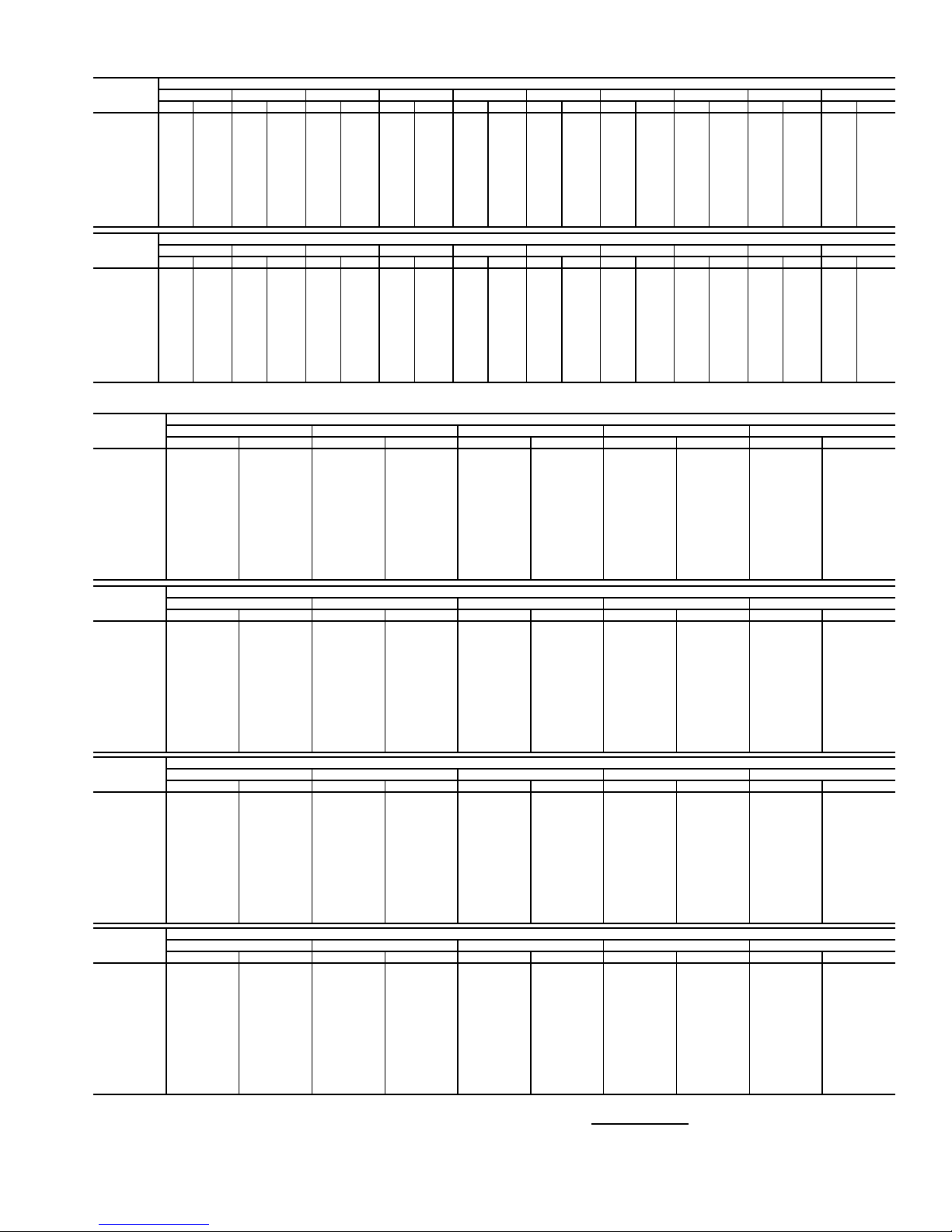
Table 9 — Fan Performance — 48AJ,AK,A2,A3050 Units
AIRFLOW
(Cfm)
8,000 512 2.98 560 3.38 604 3.79 647 4.20 688 4.62 728 5.05 766 5.49 803 5.94 839 6.40 874 6.86
9,000 561 3.90 604 4.33 645 4.77 685 5.20 723 5.65 760 6.10 796 6.55 831 7.02 864 7.49 897 7.97
10,000 611 5.00 651 5.45 689 5.91 725 6.37 761 6.84 795 7.31 829 7.79 861 8.27 893 8.76 925 9.26
11,000 662 6.27 699 6.75 734 7.23 768 7.72 801 8.21 833 8.71 865 9.20 895 9.71 925 10.21 955 10.73
12,000 714 7.74 748 8.24 780 8.75 812 9.26 843 9.77 873 10.29 903 10.81 932 11.33 960 11.86 988 12.39
13,000 766 9.41 798 9.93 828 10.46 858 11.00 887 11.54 916 12.08 944 12.62 971 13.16 998 13.71 1024 14.26
14,000 819 11.29 848 11.84 877 12.39 905 12.95 932 13.51 959 14.07 986 14.63 1012 15.20 1037 15.77 1062 16.34
15,000 872 13.40 899 13.96 926 14.54 953 15.11 979 15.70 1004 16.28 1029 16.87 1054 17.46 1078 18.05 1102 18.64
16,000 925 15.74 951 16.32 976 16.91 1001 17.51 1026 18.12 1050 18.72 1074 19.33 1097 19.94 1121 20.55 1143 21.17
17,000 979 18.32 1003 18.92 1027 19.53 1051 20.15 1074 20.77 1097 21.40 1120 22.03 1142 22.66 1164 23.29 1186 23.93
18,000 1032 21.15 1055 21.77 1078 22.40 1100 23.04 1123 23.68 1145 24.33 1166 24.98 1188 25.63 1209 26.28 1230 26.93
19,000 1086 24.24 1108 24.88 1129 25.52 1151 26.18 1172 26.84 1193 27.51 1214 28.18 1234 28.85 1255 29.52 1275 30.19
20,000 1140 27.60 1161 28.25 1181 28.92 1202 29.59 1222 30.27 1242 30.95 1262 31.64 1281 32.33 — — — —
AIRFLOW
(Cfm)
8,000 907 7.34 940 7.81 971 8.30 1001 8.79 1030 9.29 1059 9.79 1086 10.29 1113 10.80 1139 11.31 1164 11.83
9,000 930 8.46 961 8.95 991 9.46 1021 9.97 1050 10.48 1078 11.00 1105 11.52 1131 12.05 1157 12.58 1183 13.12
10,000 955 9.76 985 10.27 1014 10.79 1043 11.31 1071 11.84 1098 12.37 1125 12.91 1151 13.46 1177 14.01 1202 14.56
11,000 984 11.25 1012 11.77 1040 12.30 1068 12.84 1095 13.38 1121 13.93 1147 14.49 1172 15.05 1197 15.61 1222 16.18
12,000 1016 12.93 1043 13.47 1069 14.02 1095 14.57 1121 15.13 1147 15.69 1172 16.26 1196 16.83 1220 17.41 1244 18.00
13,000 1050 14.82 1076 15.38 1101 15.94 1126 16.51 1151 17.08 1175 17.66 1199 18.24 1223 18.83 1246 19.42 1269 20.02
14,000 1087 16.92 1111 17.49 1136 18.07 1159 18.66 1183 19.25 1206 19.84 1229 20.44 1252 21.04 1274 21.64 1296 22.25
15,000 1126 19.23 1149 19.83 1172 20.43 1195 21.03 1217 21.64 1239 22.25 1261 22.86 1283 23.48 — — — —
16,000 1166 21.78 1188 22.40 1210 23.01 1232 23.64 1253 24.26 1275 24.89 1296 25.52 — — — — — —
17,000 1208 24.56 1229 25.20 1250 25.84 1271 26.48 1291 27.12 ——————————
18,000 1250 27.59 1271 28.25 1291 28.91 ——————————————
19,000 1294 30.87 — — — ———————————————
20,000 ————————————————————
0.2 0.4 0.6 0.8 1.0 1.2 1.4 1.6 1.8 2.0
RpmBhpRpmBhpRpmBhpRpmBhpRpmBhpRpmBhpRpmBhpRpmBhpRpmBhpRpmBhp
2.2 2.4 2.6 2.8 3.0 3.2 3.4 3.6 3.8 4.0
RpmBhpRpmBhpRpmBhpRpmBhpRpmBhpRpmBhpRpmBhpRpmBhpRpmBhpRpmBhp
AVAILABLE E XTERNAL STATIC PRESSURE (in. wg)
AVAILABLE E XTERNAL STATIC PRESSURE (in. wg)
Table 10 — Fan Performance — 48AJ,AK051 Units
AIRFLOW
(Cfm)
10,000 419 2.89 483 3.54 538 4.25 587 5.00 632 5.79
12,000 476 4.33 534 5.04 585 5.78 632 6.56 674 7.39
13,000 506 5.21 561 5.94 610 6.70 655 7.50 697 8.34
14,000 536 6.18 588 6.96 636 7.74 680 8.56 720 9.41
15,000 566 7.28 617 8.09 662 8.90 704 9.73 744 10.59
16,000 597 8.48 645 9.34 689 10.17 730 11.02 768 11.90
17,000 628 9.80 674 10.71 717 11.58 756 12.45 793 13.34
18,000 659 11.25 704 12.21 745 13.11 783 14.00 819 14.91
19,000 691 12.82 734 13.84 773 14.77 810 15.69 845 16.62
20,000 723 14.53 764 15.60 802 16.57 838 17.52 872 18.47
21,000 755 16.37 794 17.49 831 18.51 866 19.49 899 20.47
22,000 787 18.35 825 19.53 861 20.59 894 21.60 927 22.61
23,000 819 20.48 856 21.71 890 22.81 923 23.87 954 24.90
24,000 851 22.75 887 24.04 920 25.19 952 26.28 983 27.34
25,000 883 25.17 918 26.52 951 27.72 982 28.84 1011 29.94
AIRFLOW
(Cfm)
10,000 673 6.60 711 7.42 747 8.26 782 9.10 815 9.96
12,000 714 8.24 751 9.12 786 10.02 819 10.92 851 11.85
13,000 735 9.22 772 10.11 806 11.03 839 11.97 870 12.92
14,000 758 10.30 793 11.21 827 12.15 859 13.11 890 14.08
15,000 781 11.50 816 12.43 849 13.38 881 14.35 911 15.35
16,000 804 12.82 839 13.76 871 14.73 902 15.72 932 16.73
17,000 829 14.27 862 15.23 894 16.21 925 17.21 954 18.24
18,000 853 15.85 886 16.82 918 17.82 948 18.84 977 19.88
19,000 879 17.58 911 18.56 942 19.57 971 20.60 1000 21.65
20,000 905 19.44 936 20.44 966 21.45 995 22.50 1023 23.57
21,000 931 21.46 961 22.47 991 23.50 1019 24.55 1047 25.63
22,000 958 23.62 987 24.64 1016 25.69 1044 26.76 1071 27.84
23,000 985 25.93 1014 26.97 1042 28.03 1069 29.11 1096 30.21
24,000
25,000 1040 31.02 1068 32.11 1095 33.21 1121 34.31 1147 35.44
AIRFLOW
(Cfm)
10,000 846 10.82 876 11.69 906 12.56 934 13.44 961 14.32
12,000 881 12.78 911 13.72 939 14.67 967 15.62 993 16.58
13,000 900 13.88 929 14.85 957 15.82 984 16.81 1011 17.80
14,000 920 15.06 948 16.06 976 17.07 1003 18.08 1029 19.11
15,000 940 16.36 968 17.38 996 18.41 1022 19.45 1048 20.50
16,000 961 17.76 989 18.80 1016 19.86 1042 20.92 1067 22.00
17,000 983 19.28 1010 20.34 1036 21.42 1062 22.51 1087 23.60
18,000 1005 20.94 1032 22.01 1058 23.11 1083 24.21 1108 25.33
19,000 1027 22.72 1054 23.81 1080 24.92 1105 26.04 1129 27.18
20,000 1050 24.65 1076 25.76 1102 26.88 1126 28.01 1151 29.17
21,000 1073 26.73 1099 27.84 1124 28.97 1149 30.13 1173 31.29
22,000 1097 28.95 1123 30.08 1147 31.22 1172 32.39 1195 33.56
23,000 1122 31.33 1147 32.47 1171 33.63 1195 34.80 — —
24,000 1146 33.87 1171 35.02 1195 36.19 — — — —
25,000 1171 36.58 1196 37.74 ——————
AIRFLOW
(Cfm)
10,000 988 15.21 1014 16.09 1039 16.98 1063 17.88 1087 18.77
12,000 1019 17.54 1045 18.51 1069 19.48 1093 20.45 1117 21.43
13,000 1036 18.80 1061 19.80 1086 20.81 1109 21.82 1133 22.84
14,000 1054 20.13 1079 21.17 1103 22.21 1126 23.26 1149 24.31
15,000 1073 21.56 1097 22.63 1121 23.70 1144 24.78 1167 25.86
16,000 1092 23.08 1116 24.17 1140 25.28 1162 26.38 1185 27.49
17,000 1112 24.71 1135 25.83 1159 26.95 1181 28.09 — —
18,000 1132 26.46 1156 27.60 1178 28.74 — — — —
19,000 1153 28.33 1176 29.48 1199 30.65 — — — —
20,000 1174 30.33 1197 31.50 ——————
21,000 119632.47————————
22,000 ——————————
23,000 ——————————
24,000 ——————————
25,000 ——————————
LEGEND
Bhp — Brake Horsepower
edb — Entering Dry Bulb
ewb — Entering Wet Bulb
NOTES:
1. Fan performance is based on wet coils, economizer, roof curb, cabinet losses, and clean 2-in.
filters.
0.2 0.4 0.6 0.8 1.0
Rpm Bhp Rpm Bhp Rpm Bhp Rpm Bhp Rpm Bhp
1.2 1.4 1.6 1.8 2.0
Rpm Bhp Rpm Bhp Rpm Bhp Rpm Bhp Rpm Bhp
1012 28.40 1041 29.46 1068 30.54 1095 31.63 1121 32.74
2.2 2.4 2.6 2.8 3.0
Rpm Bhp Rpm Bhp Rpm Bhp Rpm Bhp Rpm Bhp
3.2 3.4 3.6 3.8 4.0
Rpm Bhp Rpm Bhp Rpm Bhp Rpm Bhp Rpm Bhp
AVAILABLE EXTERNAL STATIC PRESSURE (in. wg)
AVAILABLE EXTERNAL STATIC PRESSURE (in. wg)
AVAILABLE EXTERNAL STATIC PRESSURE (in. wg)
AVAILABLE EXTERNAL STATIC PRESSURE (in. wg)
2. Conversion — Bhp to watts:
Watts =
3. Variable air volume units will operate down to 70 cfm/ton. Performance at 70 cfm/ton is limited to
unloaded operation and may be additionally limited by edb and ewb conditions.
Bhp x 746
Motor efficiency
11
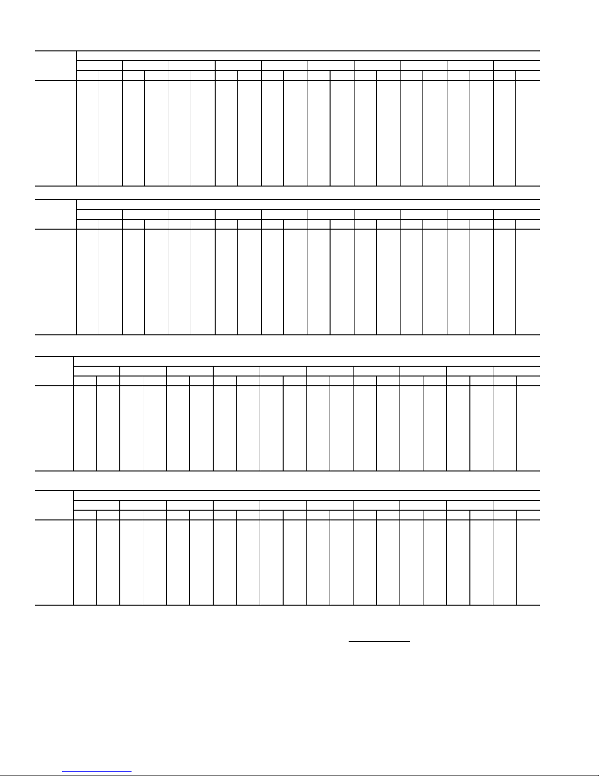
Table 11 — Fan Performance — 48AJ,AK,A2,A3060 Units
AIRFLOW
(Cfm)
12,000 476 4.33 534 5.04 585 5.78 632 6.56 674 7.39 714 8.24 751 9.12 786 10.02 819 10.93 851 11.85
14,000 536 6.19 588 6.96 636 7.74 680 8.56 720 9.41 758 10.30 793 11.21 827 12.15 859 13.11 890 14.08
15,000 566 7.28 617 8.09 662 8.90 704 9.73 744 10.59 781 11.50 816 12.42 849 13.38 881 14.36 911 15.35
16,000 597 8.48 645 9.34 689 10.17 730 11.02 768 11.90 804 12.82 839 13.76 871 14.73 902 15.72 932 16.73
17,000 628 9.80 674 10.71 717 11.58 756 12.45 793 13.34 829 14.27 862 15.23 894 16.21 925 17.21 954 18.24
18,000 659 11.25 704 12.21 745 13.11 783 14.00 819 14.91 853 15.85 886 16.82 918 17.82 948 18.84 977 19.88
19,000 691 12.82 734 13.84 773 14.77 810 15.69 845 16.62 879 17.58 911 18.56 942 19.57 971 20.60 1000 21.65
20,000 723 14.53 764 15.60 802 16.57 838 17.52 872 18.47 905 19.44 936 20.44 966 21.45 995 22.50 1023 23.57
21,000 755 16.37 794 17.49 831 18.51 866 19.49 899 20.47 931 21.46 961 22.47 991 23.50 1019 24.55 1047 25.63
22,000 787 18.35 825 19.53 861 20.59 894 21.60 927 22.61 958 23.62 987 24.64 1016 25.69 1044 26.76 1071 27.84
23,000 819 20.48 856 21.71 890 22.81 923 23.87 954 24.90 985 25.93 1014 26.97 1042 28.03 1069 29.11 1096 30.21
24,000 851 22.75 887 24.04 920 25.19 952 26.28 983 27.34 1012 28.40 1041 29.46 1068 30.54 1095 31.63 1121 32.74
25,000 883 25.17 918 26.52 951 27.72 982 28.84 1011 29.94 1040 31.02 1068 32.11 1095 33.21 1121 34.31 1147 35.44
26,000 916 27.76 950 29.15 981 30.40 1011 31.57 1040 32.70 1068 33.81 1095 34.92 1122 36.04 1147 37.16 1172 38.30
27,000 948 30.49 981 31.95 1012 33.24 1041 34.46 1070 35.62 1097 36.76 1123 37.90 1149 39.04 1174 40.18 1199 41.34
0.2 0.4 0.6 0.8 1.0 1.2 1.4 1.6 1.8 2.0
Rpm Bhp Rpm Bhp Rpm Bhp Rpm Bhp Rpm Bhp Rpm Bhp Rpm Bhp Rpm Bhp Rpm Bhp Rpm Bhp
AVAILABLE EXTERNAL STATIC PRESSURE (in. wg)
AIRFLOW
(Cfm)
12,000 881 12.78 911 13.72 939 14.67 967 15.62 993 16.58 1019 17.54 1045 18.51 1069 19.48 1093 20.45 1117 21.43
14,000 920 15.06 948 16.06 976 17.07 1003 18.08 1029 19.11 1054 20.13 1079 21.17 1103 22.21 1126 23.26 1149 24.31
15,000 940 16.36 968 17.38 996 18.41 1022 19.45 1048 20.50 1073 21.56 1097 22.63 1121 23.70 1144 24.78 1167 25.86
16,000 961 17.76 989 18.80 1016 19.86 1042 20.92 1067 22.00 1092 23.08 1116 24.17 1140 25.28 1162 26.38 1185 27.49
17,000 983 19.28 1010 20.34 1036 21.42 1062 22.51 1087 23.60 1112 24.71 1135 25.83 1159 26.95 1181 28.09 — —
18,000 1005 20.94 1032 22.01 1058 23.11 1083 24.21 1108 25.33 1132 26.46 1156 27.60 1178 28.74 — — — —
19,000 1027 22.72 1054 23.81 1080 24.92 1105 26.04 1129 27.18 1153 28.33 1176 29.48 1199 30.65 — — — —
20,000 1050 24.65 1076 25.76 1102 26.88 1126 28.01 1151 29.17 1174 30.33 1197 31.50 — — — — — —
21,000 1073 26.73 1099 27.84 1124 28.97 1149 30.13 1173 31.29 1196 32.47 — ———————
22,000 1097 28.95 1123 30.08 1147 31.22 1172 32.39 1195 33.56 — — — ———————
23,000 112231.33114732.47117133.63119534.80————————————
24,000 114633.87117135.02119536.19——————————————
25,000 117136.58119637.74————————————————
26,000 119739.46——————————————————
27,000 ————————————————————
2.2 2.4 2.6 2.8 3.0 3.2 3.4 3.6 3.8 4.0
Rpm Bhp Rpm Bhp Rpm Bhp Rpm Bhp Rpm Bhp Rpm Bhp Rpm Bhp Rpm Bhp Rpm Bhp Rpm Bhp
AVAILABLE EXTERNAL STATIC PRESSURE (in. wg)
Table 12 — Fan Performance — 50AJ,AK020,025 and 50A2,A3020 Units
AIRFLOW
(CFM)
4,000 311 0.54 390 0.71 457 0.88 515 1.05 567 1.21 613 1.38 656 1.55 696 1.71 733 1.88 768 2.04
5,000 347 0.84 417 1.02 480 1.21 536 1.40 587 1.59 633 1.78 676 1.97 716 2.16 753 2.34 788 2.52
6,000 387 1.25 450 1.43 507 1.63 560 1.84 609 2.05 654 2.26 696 2.47 735 2.68 773 2.88 808 3.09
7,000 430 1.77 488 1.96 540 2.17 588 2.38 634 2.61 677 2.83 718 3.06 756 3.29 793 3.51 828 3.74
7,500 452 2.07 507 2.27 557 2.48 604 2.70 648 2.93 690 3.16 730 3.40 768 3.63 804 3.87 839 4.10
8,000 474 2.41 528 2.61 576 2.82 620 3.04 663 3.28 704 3.52 743 3.76 780 4.00 816 4.24 850 4.48
9,000 519 3.19 570 3.39 614 3.60 656 3.83 696 4.07 734 4.32 771 4.57 806 4.82 840 5.08 873 5.34
10,000 565 4.10 613 4.31 655 4.53 694 4.76 731 5.00 767 5.26 802 5.51 835 5.78 868 6.04 900 6.31
11,000 611 5.17 657 5.37 697 5.60 734 5.84 769 6.08 803 6.34 836 6.60 868 6.87 899 7.15 929 7.42
12,000 658 6.39 702 6.60 741 6.83 776 7.07 809 7.32 841 7.58 872 7.85 902 8.12 932 8.40 960 8.68
12,500 681 7.06 725 7.27 763 7.50 797 7.74 830 8.00 861 8.26 891 8.53 920 8.80 949 9.08 977 9.37
13,000 705 7.77 748 7.98 785 8.21 819 8.46 850 8.71 881 8.98 910 9.25 939 9.53 967 9.81 994 10.10
0.2 0.4 0.6 0.8 1.0 1.2 1.4 1.6 1.8 2.0
Rpm Bhp Rpm Bhp Rpm Bhp Rpm Bhp Rpm Bhp Rpm Bhp Rpm Bhp Rpm Bhp Rpm Bhp Rpm Bhp
AVAILABLE EXTERNAL STATIC PRESSURE (in. wg)
AIRFLOW
(CFM)
4,000 802 2.21 833 2.38 864 2.55 893 2.71 921 2.88 949 3.06 975 3.23 1001 3.40 1026 3.58 1050 3.75
5,000 822 2.71 854 2.89 885 3.08 914 3.26 943 3.45 970 3.64 997 3.82 1023 4.01 1048 4.20 1072 4.39
6,000 842 3.29 874 3.50 905 3.70 934 3.90 963 4.10 991 4.31 1017 4.51 1043 4.71 1069 4.91 1093 5.12
7,000 862 3.96 894 4.19 924 4.41 954 4.63 983 4.85 1010 5.07 1037 5.29 1063 5.51 1089 5.72 1113 5.94
7,500 872 4.33 904 4.56 934 4.79 964 5.02 993 5.25 1020 5.48 1047 5.71 1073 5.94 1099 6.16 1123 6.39
8,000 883 4.73 914 4.97 945 5.21 974 5.45 1003 5.68 1030 5.92 1057 6.16 1083 6.39 1108 6.63 1133 6.87
9,000 905 5.60 936 5.85 966 6.11 995 6.37 1023 6.62 1051 6.88 1077 7.13 1103 7.38 1129 7.64 1153 7.89
10,000 931 6.58 961 6.85 990 7.13 1018 7.40 1046 7.67 1073 7.94 1099 8.21 1124 8.48 1149 8.75 1174 9.02
11,000 958 7.70 987 7.99 1015 8.27 1043 8.55 1070 8.84 1096 9.12 1122 9.41 1147 9.69 1171 9.98 1195 10.26
12,000 989 8.97 1016 9.26 1043 9.55 1070 9.85 1096 10.14 1121 10.44 1146 10.73 1171 11.03 1195 11.33 — —
12,500 1005 9.66 1032 9.95 1058 10.25 1084 10.55 1110 10.85 1135 11.15 1159 11.45 1183 11.75 — — — —
13,000 1021 10.39 1048 10.69 1074 10.99 1099 11.29 1124 11.59 1149 11.90 1173 12.20 1197 12.51 — — — —
LEGEND
Bhp — Brake Horsepower
edb — Entering Dry Bulb
ewb — Entering Wet Bulb
NOTES:
1. Fan performance is based on wet coils, economizer, roof curb, cabinet
losses, and clean 2-in. filters.
2.2 2.4 2.6 2.8 3.0 3.2 3.4 3.6 3.8 4.0
Rpm Bhp Rpm Bhp Rpm Bhp Rpm Bhp Rpm Bhp Rpm Bhp Rpm Bhp Rpm Bhp Rpm Bhp Rpm Bhp
AVAILABLE EXTERNAL STATIC PRESSURE (in. wg)
2. Conversion — Bhp to watts:
Watts =
3. Variable air volume units will operate down to 70 cfm/ton. Performance at
70 cfm/ton is limited to unloaded operation and may be additionally limited
by edb and ewb conditions.
Bhp x 746
Motor efficiency
12
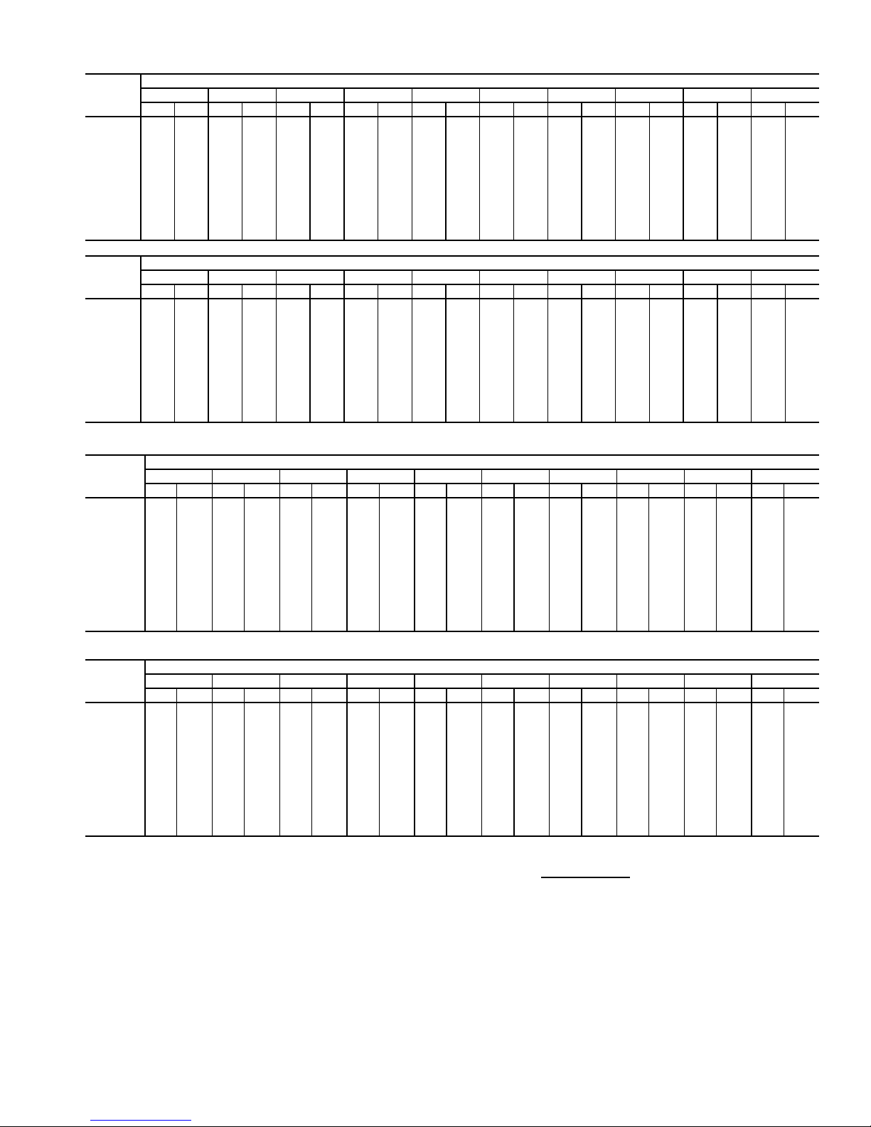
Table 13 — Fan Performance — 50AJ,AK027,030 and 50A2,A3025-030 Units
AIRFLOW
(CFM)
4,000 314 0.54 394 0.72 460 0.89 517 1.05 569 1.22 615 1.39 658 1.55 697 1.72 734 1.88 769 2.05
5,000 352 0.85 422 1.03 484 1.22 540 1.42 590 1.61 636 1.79 678 1.98 718 2.17 755 2.35 791 2.54
6,000 394 1.26 456 1.45 513 1.65 565 1.86 613 2.07 658 2.28 700 2.49 739 2.70 776 2.90 811 3.11
7,000 438 1.79 495 1.98 546 2.19 594 2.41 640 2.64 682 2.86 723 3.09 761 3.32 798 3.54 833 3.77
8,000 483 2.44 536 2.64 583 2.85 628 3.08 670 3.32 710 3.55 749 3.80 786 4.04 821 4.28 855 4.52
9,000 530 3.23 579 3.43 623 3.65 664 3.88 704 4.12 741 4.37 778 4.62 813 4.88 847 5.13 880 5.39
10,000 577 4.15 624 4.36 665 4.58 703 4.82 740 5.06 776 5.32 810 5.58 843 5.84 876 6.11 907 6.38
11,000 625 5.22 669 5.44 708 5.67 744 5.91 779 6.16 813 6.41 845 6.68 877 6.95 907 7.22 937 7.50
12,000 674 6.45 715 6.67 753 6.90 787 7.15 820 7.40 851 7.67 882 7.93 912 8.21 941 8.49 970 8.78
13,000 722 7.85 762 8.07 798 8.30 831 8.55 862 8.81 892 9.08 921 9.35 950 9.63 977 9.92 1005 10.21
14,000 771 9.41 810 9.64 844 9.88 875 10.13 905 10.39 934 10.66 962 10.94 989 11.22 1015 11.51 1041 11.81
15,000 821 11.15 857 11.38 890 11.62 921 11.88 949 12.14 977 12.42 1004 12.70 1030 12.99 1055 13.28 1080 13.58
0.2 0.4 0.6 0.8 1.0 1.2 1.4 1.6 1.8 2.0
Rpm Bhp Rpm Bhp Rpm Bhp Rpm Bhp Rpm Bhp Rpm Bhp Rpm Bhp Rpm Bhp Rpm Bhp Rpm Bhp
AVAILABLE EXTERNAL STATIC PRESSURE (in. wg)
AIRFLOW
(CFM)
4,000 803 2.22 835 2.38 865 2.55 894 2.72 923 2.89 950 3.06 976 3.24 1002 3.41 1027 3.58 1051 3.76
5,000 824 2.72 856 2.91 887 3.09 916 3.28 945 3.46 972 3.65 999 3.83 1024 4.02 1049 4.21 1074 4.40
6,000 845 3.31 877 3.52 908 3.72 937 3.92 966 4.12 993 4.32 1020 4.53 1046 4.73 1071 4.93 1096 5.14
7,000 866 3.99 898 4.21 928 4.43 958 4.66 986 4.88 1014 5.10 1041 5.31 1067 5.53 1092 5.75 1116 5.97
8,000 888 4.77 919 5.01 950 5.25 979 5.49 1007 5.72 1035 5.96 1061 6.20 1087 6.43 1113 6.67 1137 6.90
9,000 912 5.65 942 5.90 972 6.16 1001 6.42 1029 6.67 1056 6.93 1083 7.18 1108 7.43 1134 7.69 1158 7.94
10,000 938 6.65 968 6.92 997 7.19 1025 7.46 1052 7.73 1079 8.00 1105 8.27 1130 8.54 1155 8.81 1180 9.08
11,000 967 7.78 995 8.07 1023 8.35 1051 8.63 1077 8.92 1103 9.20 1129 9.49 1154 9.77 1178 10.06 — —
12,000 998 9.07 1025 9.35 1052 9.65 1078 9.94 1104 10.24 1130 10.54 1154 10.83 1179 11.13 — — — —
13,000 1031 10.50 1058 10.80 1083 11.10 1109 11.40 1133 11.71 1158 12.01 1182 12.32 — — — — — —
14,000 1067 12.10 1092 12.41 1117 12.71 1141 13.02 1165 13.33 1188 13.65 — — — — — — — —
15,000 1104 13.88 1128 14.19 1152 14.50 1175 14.81 1198 15.13 — — — — — — — — — —
2.2 2.4 2.6 2.8 3.0 3.2 3.4 3.6 3.8 4.0
Rpm Bhp Rpm Bhp Rpm Bhp Rpm Bhp Rpm Bhp Rpm Bhp Rpm Bhp Rpm Bhp Rpm Bhp Rpm Bhp
AVAILABLE EXTERNAL STATIC PRESSURE (in. wg)
Table 14 — Fan Performance — 50AJ,AKA2,A3035 Units
AIRFLOW
(Cfm)
7,000 503 1.96 553 2.22 601 2.47 646 2.72 689 2.97 730 3.22 768 3.46 804 3.70 839 3.94 872 4.17
8,000 553 2.62 599 2.89 643 3.16 684 3.43 724 3.70 763 3.97 799 4.23 834 4.50 868 4.76 901 5.02
9,000 605 3.39 647 3.68 687 3.97 726 4.26 763 4.55 798 4.83 833 5.12 867 5.40 899 5.68 930 5.96
10,000 657 4.29 696 4.61 733 4.91 769 5.22 803 5.52 837 5.82 870 6.12 901 6.42 932 6.72 962 7.02
10,500 684 4.80 721 5.12 757 5.43 791 5.75 825 6.06 857 6.37 889 6.68 920 6.98 950 7.29 979 7.60
11,000 710 5.33 747 5.66 781 5.99 814 6.31 847 6.63 878 6.95 909 7.26 939 7.58 968 7.89 997 8.21
12,000 764 6.52 798 6.86 830 7.21 861 7.54 891 7.88 921 8.21 950 8.54 978 8.87 1006 9.20 1033 9.53
13,000 818 7.85 849 8.21 880 8.57 909 8.92 938 9.27 966 9.62 993 9.97 1020 10.31 1046 10.66 1072 11.00
14,000 872 9.33 901 9.71 930 10.09 958 10.45 985 10.82 1012 11.19 1037 11.55 1063 11.91 1088 12.27 1113 12.63
15,000 926 10.98 954 11.37 981 11.76 1008 12.15 1033 12.53 1059 12.91 1083 13.28 1108 13.66 1131 14.03 1155 14.40
16,000 980 12.79 1007 13.20 1033 13.60 1058 14.00 1082 14.40 1106 14.79 1130 15.18 1153 15.57 1176 15.96 1199 16.35
17,000 1035 14.77 1060 15.19 1085 15.61 1109 16.03 1132 16.44 1155 16.84 1178 17.25 1200 17.65 1222 18.05 1243 18.46
17,500 1062 15.83 1087 16.25 1111 16.68 1134 17.10 1157 17.52 1180 17.94 1202 18.35 1224 18.76 1245 19.17 1266 19.58
AIRFLOW
(Cfm)
7,000 903 4.40 933 4.62 962 4.84 990 5.06 1017 5.27 1043 5.48 1068 5.69 1092 5.89 1116 6.09 1139 6.28
8,000 932 5.27 962 5.52 991 5.77 1019 6.02 1045 6.26 1071 6.50 1097 6.73 1121 6.96 1145 7.19 1168 7.42
9,000 961 6.24 990 6.52 1019 6.79 1047 7.06 1073 7.33 1099 7.59 1125 7.85 1149 8.11 1173 8.37 1196 8.62
10,000 992 7.32 1020 7.62 1048 7.91 1075 8.20 1102 8.49 1127 8.78 1152 9.07 1177 9.35 1201 9.63 1224 9.91
10,500 1008 7.90 1036 8.21 1063 8.51 1090 8.82 1116 9.12 1142 9.41 1166 9.71 1191 10.01 1214 10.30 1238 10.59
11,000 1025 8.52 1052 8.84 1079 9.15 1105 9.46 1131 9.77 1156 10.08 1181 10.39 1205 10.69 1228 10.99 1252 11.29
12,000 1060 9.86 1086 10.19 1112 10.52 1137 10.85 1162 11.17 1187 11.50 1211 11.82 1234 12.15 1257 12.47 1280 12.79
13,000 1097 11.35 1122 11.69 1147 12.03 1171 12.37 1195 12.72 1219 13.06 1242 13.40 1265 13.74 1287 14.08 — —
14,000 1137 12.98 1161 13.34 1184 13.69 1208 14.05 1231 14.41 1253 14.76 1276 15.12 1298 15.47 — — — —
15,000 1178 14.77 1201 15.15 1223 15.51 1246 15.88 1268 16.25 1289 16.62 ————————
16,000 122116.73124317.11126417.50128617.88————————————
17,000 126518.85128619.25————————————————
17,500 128719.98——————————————————
LEGEND
Bhp — Brake Horsepower
edb — Entering Dry Bulb
ewb — Entering Wet Bulb
NOTES:
1. Fan performance is based on wet coils, economizer, roof curb, cabinet
losses, and clean 2-in. filters.
0.2 0.4 0.6 0.8 1.0 1.2 1.4 1.6 1.8 2.0
Rpm Bhp Rpm Bhp Rpm Bhp Rpm Bhp Rpm Bhp Rpm Bhp Rpm Bhp Rpm Bhp Rpm Bhp Rpm Bhp
2.2 2.4 2.6 2.8 3.0 3.2 3.4 3.6 3.8 4.0
Rpm Bhp Rpm Bhp Rpm Bhp Rpm Bhp Rpm Bhp Rpm Bhp Rpm Bhp Rpm Bhp Rpm Bhp Rpm Bhp
AVAILABLE EXTERNAL STATIC PRESSURE (in. wg)
AVAILABLE EXTERNAL STATIC PRESSURE (in. wg)
2. Conversion — Bhp to watts:
Watts =
3. Variable air volume units will operate down to 70 cfm/ton. Performance at
70 cfm/ton is limited to unloaded operation and may be additionally limited
by edb and ewb conditions.
Bhp x 746
Motor efficiency
13

Table 15 — Fan Performance — 50AJ,AK036 Units
AIRFLOW
(Cfm)
7,000 431 1.99 484 2.35 534 2.72 580 3.08 625 3.46
8,000 475 2.69 523 3.08 569 3.47 612 3.86 653 4.26
9,000 521 3.53 565 3.94 606 4.36 646 4.78 684 5.20
10,000 568 4.52 608 4.96 646 5.40 683 5.84 719 6.29
11,000 615 5.68 652 6.14 687 6.60 722 7.07 755 7.55
12,000 663 7.01 697 7.49 730 7.98 762 8.47 794 8.97
13,000 712 8.53 743 9.03 774 9.54 804 10.05 834 10.57
14,000 760 10.24 790 10.76 819 11.29 847 11.82 875 12.36
15,000 809 12.15 837 12.69 864 13.24 891 13.79 917 14.35
16,000 859 14.27 885 14.83 910 15.40 936 15.97 960 16.55
17,000 908 16.61 933 17.19 957 17.77 981 18.36 1004 18.96
17,500 933 17.87 957 18.45 981 19.04 1004 19.64 1027 20.25
AIRFLOW
(Cfm)
7,000 667 3.85 707 4.24 746 4.65 783 5.07 819 5.49
8,000 692 4.66 730 5.07 767 5.49 802 5.92 836 6.36
9,000 721 5.63 757 6.06 791 6.49 825 6.94 857 7.39
10,000 753 6.74 787 7.20 819 7.65 851 8.11 882 8.58
11,000 788 8.02 819 8.50 850 8.97 880 9.46 909 9.94
12,000 824 9.47 854 9.96 883 10.47 912 10.97 939 11.48
13,000 862 11.09 891 11.61 918 12.13 945 12.66 972 13.19
14,000 902 12.90 929 13.45 955 13.99 981 14.54 1006 15.09
15,000 943 14.91 968 15.48 993 16.04 1018 16.62 1042 17.18
16,000 985 17.13 1009 17.71 1033 18.30 1056 18.89 1079 19.48
17,000 1028 19.56 1051 20.16 1073 20.77 1096 21.38 1118 21.99
17,500 1049 20.86 1072 21.47 1094 22.09 1116 22.71 1137 23.33
AIRFLOW
(Cfm)
7,000 854 5.93 887 6.37 919 6.82 950 7.28 980 7.74
8,000 870 6.81 902 7.26 933 7.73 964 8.20 993 8.67
9,000 889 7.85 920 8.31 950 8.79 979 9.27 1008 9.75
10,000 912 9.05 941 9.53 970 10.02 998 10.51 1026 11.00
11,000 938 10.43 966 10.92 993 11.42 1020 11.93 1047 12.44
12,000 967 11.98 993 12.49 1020 13.01 1046 13.53 1071 14.05
13,000 998 13.72 1023 14.25 1049 14.78 1073 15.32 1098 15.86
14,000 1031 15.64 1055 16.19 1079 16.75 1103 17.30 1126 17.86
15,000 1066 17.76 1089 18.33 1112 18.90 1135 19.48 1157 20.06
16,000 1102 20.08 1124 20.67 1147 21.26 1168 21.86 1190 22.46
17,000 1140 22.61 1161 23.22 1182 23.84 1203 24.45 1224 25.07
17,500 1159 23.95 1180 24.58 1201 25.21 1221 25.83 1242 26.46
AIRFLOW
(Cfm)
7,000 1009 8.21 1037 8.69 1064 9.17 1091 9.65 1116 10.14
8,000 1022 9.16 1050 9.65 1077 10.14 1104 10.64 1129 11.15
9,000 1036 10.25 1064 10.75 1090 11.26 1117 11.77 1142 12.29
10,000 1053 11.51 1080 12.02 1106 12.54 1131 13.06 1157 13.59
11,000 1073 12.95 1099 13.47 1124 14.00 1149 14.53 1173 15.07
12,000 1096 14.58 1121 15.11 1145 15.65 1169 16.19 1192 16.74
13,000 1121 16.40 1145 16.95 1168 17.50 1191 18.06 1214 18.62
14,000 1149 18.42 1172 18.98 1195 19.55 1217 20.12 1239 20.69
15,000 1179 20.63 1201 21.21 1223 21.80 1244 22.38 1265 22.97
16,000 1211 23.06 1232 23.66 1253 24.26 1274 24.86 1294 25.46
17,000 1245 25.69 1265 26.31 1285 26.93 — — — —
17,500 126227.09128227.71——————
0.2 0.4 0.6 0.8 1.0
Rpm Bhp Rpm Bhp Rpm Bhp Rpm Bhp Rpm Bhp
1.2 1.4 1.6 1.8 2.0
Rpm Bhp Rpm Bhp Rpm Bhp Rpm Bhp Rpm Bhp
2.2 2.4 2.6 2.8 3.0
Rpm Bhp Rpm Bhp Rpm Bhp Rpm Bhp Rpm Bhp
3.2 3.4 3.6 3.8 4.0
Rpm Bhp Rpm Bhp Rpm Bhp Rpm Bhp Rpm Bhp
AVAILABLE EXTERNAL STATIC PRESSURE (in. wg)
AVAILABLE EXTERNAL STATIC PRESSURE (in. wg)
AVAILABLE EXTERNAL STATIC PRESSURE (in. wg)
AVAILABLE EXTERNAL STATIC PRESSURE (in. wg)
Table 16 — Fan Performance — 50AJ,AK,A2,A3040 Units
AIRFLOW
(Cfm)
8,000 475 2.69 523 3.08 569 3.47 612 3.86 653 4.26 692 4.66 730 5.07 767 5.49 802 5.92 836 6.36
9,000 521 3.53 565 3.94 606 4.36 646 4.78 684 5.20 721 5.63 757 6.06 791 6.49 825 6.94 857 7.39
10,000 568 4.52 608 4.96 646 5.40 683 5.84 719 6.29 753 6.74 787 7.20 819 7.65 851 8.11 882 8.58
11,000 615 5.68 652 6.14 687 6.60 722 7.07 755 7.55 788 8.02 819 8.50 850 8.97 880 9.46 909 9.94
12,000 663 7.01 697 7.49 730 7.98 762 8.47 794 8.97 824 9.47 854 9.96 883 10.47 912 10.97 939 11.48
13,000 712 8.53 743 9.03 774 9.54 804 10.05 834 10.57 862 11.09 891 11.61 918 12.13 945 12.66 972 13.19
14,000 760 10.24 790 10.76 819 11.29 847 11.82 875 12.36 902 12.90 929 13.45 955 13.99 981 14.54 1006 15.09
15,000 809 12.15 837 12.69 864 13.24 891 13.79 917 14.35 943 14.91 968 15.48 993 16.04 1018 16.62 1042 17.18
16,000 859 14.27 885 14.83 910 15.40 936 15.97 960 16.55 985 17.13 1009 17.71 1033 18.30 1056 18.89 1079 19.48
17,000 908 16.61 933 17.19 957 17.77 981 18.36 1004 18.96 1028 19.56 1051 20.16 1073 20.77 1096 21.38 1118 21.99
18,000 958 19.18 981 19.77 1004 20.37 1027 20.98 1049 21.60 1071 22.22 1093 22.84 1115 23.46 1136 24.09 1157 24.72
19,000 1007 21.98 1030 22.59 1052 23.21 1073 23.84 1095 24.47 1116 25.10 1137 25.74 1157 26.39 1178 27.04 1198 27.68
20,000 105725.02107925.65109926.29112026.93114027.58116128.23118128.89——————
AIRFLOW
(Cfm)
8,000 870 6.81 902 7.26 933 7.73 964 8.20 993 8.67 1022 9.16 1050 9.65 1077 10.14 1104 10.64 1129 11.15
9,000 889 7.85 920 8.31 950 8.79 979 9.27 1008 9.75 1036 10.25 1064 10.75 1090 11.26 1117 11.77 1142 12.29
10,000 912 9.05 941 9.53 970 10.02 998 10.51 1026 11.00 1053 11.51 1080 12.02 1106 12.54 1131 13.06 1157 13.59
11,000 938 10.43 966 10.92 993 11.42 1020 11.93 1047 12.44 1073 12.95 1099 13.47 1124 14.00 1149 14.53 1173 15.07
12,000 967 11.98 993 12.49 1020 13.01 1046 13.53 1071 14.05 1096 14.58 1121 15.11 1145 15.65 1169 16.19 1192 16.74
13,000 998 13.72 1023 14.25 1049 14.78 1073 15.32 1098 15.86 1121 16.40 1145 16.95 1168 17.50 1191 18.06 1214 18.62
14,000 1031 15.64 1055 16.19 1079 16.75 1103 17.30 1126 17.86 1149 18.42 1172 18.98 1195 19.55 1217 20.12 1239 20.69
15,000 1066 17.76 1089 18.33 1112 18.90 1135 19.48 1157 20.06 1179 20.63 1201 21.21 1223 21.80 1244 22.38 1265 22.97
16,000 1102 20.08 1124 20.67 1147 21.26 1168 21.86 1190 22.46 1211 23.06 1232 23.66 1253 24.26 1274 24.86 1294 25.46
17,000 114022.61116123.22118223.84120324.45122425.07124525.69126526.31128526.93————
18,000 117825.36119925.99121926.63124027.26126027.90127928.54129929.18——————
19,000 121828.34123828.99————————————————
20,000 ————————————————————
LEGEND
Bhp — Brake Horsepower
edb — Entering Dry Bulb
ewb — Entering Wet Bulb
NOTES:
1. Fan performance is based on wet coils, economizer, roof curb, cabinet losses, and clean
2-in. filters.
0.20.40.60.81.01.21.41.61.82.0
RpmBhpRpmBhpRpmBhpRpmBhpRpmBhpRpmBhpRpmBhpRpmBhpRpmBhpRpmBhp
2.22.42.62.83.03.23.43.63.84.0
RpmBhpRpmBhpRpmBhpRpmBhpRpmBhpRpmBhpRpmBhpRpmBhpRpmBhpRpmBhp
AVAILABLE EXTERNAL STATIC PRESSURE (in. wg)
AVAILABLE EXTERNAL STATIC PRESSURE (in. wg)
2. Conversion — Bhp to watts:
Watts =
3. Variable air volume units will operate down to 70 cfm/ton. Performance at 70 cfm/ton is
limited to unloaded operation and may be additionally limited by edb and ewb conditions.
Bhp x 746
Motor efficiency
14
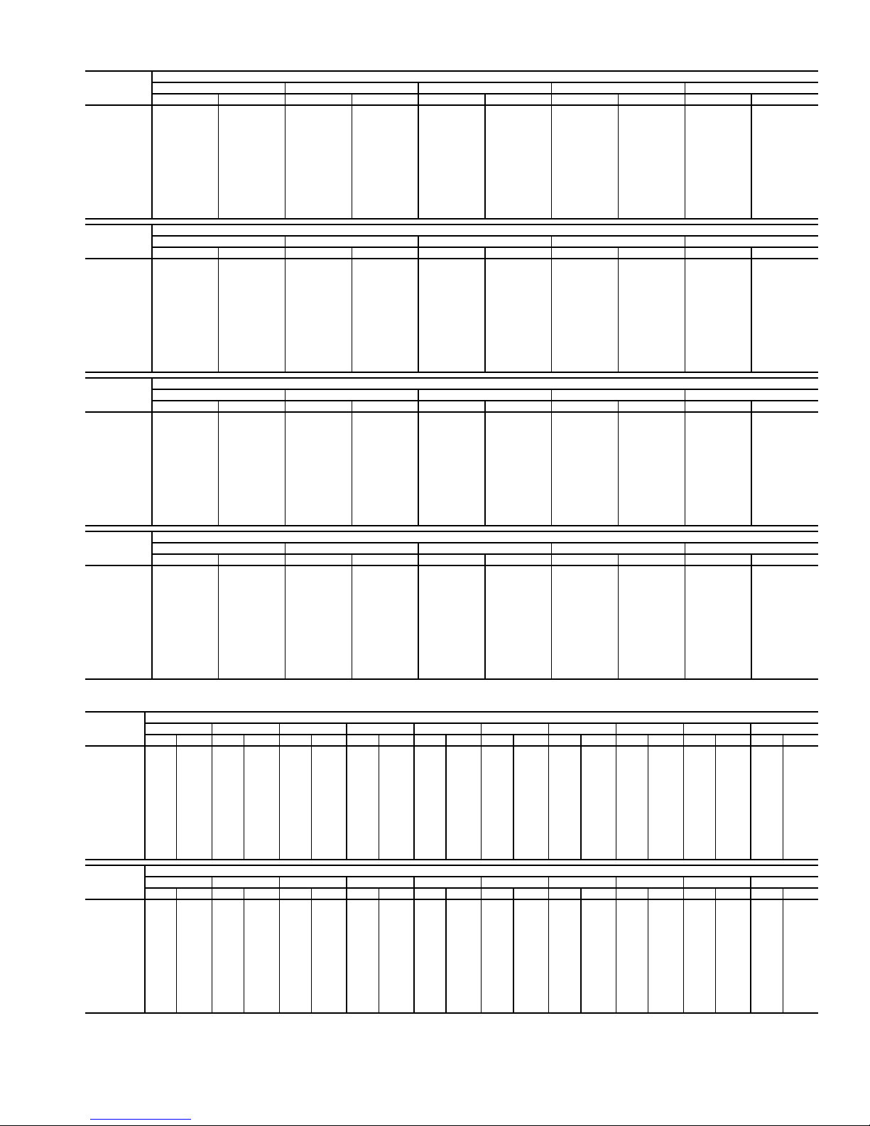
Table 17 — Fan Performance — 50AJ,AK041 Units
AIRFLOW
(Cfm)
8,000 475 2.69 523 3.08 569 3.47 612 3.86 653 4.26
9,000 521 3.53 565 3.94 606 4.36 646 4.78 684 5.20
10,000 568 4.52 608 4.96 646 5.40 683 5.84 719 6.29
11,000 615 5.68 652 6.14 687 6.60 722 7.07 755 7.55
12,000 663 7.01 697 7.49 730 7.98 762 8.47 794 8.97
13,000 712 8.53 743 9.03 774 9.54 804 10.05 834 10.57
14,000 760 10.24 790 10.76 819 11.29 847 11.82 875 12.36
15,000 809 12.15 837 12.69 864 13.24 891 13.79 917 14.35
16,000 859 14.27 885 14.83 910 15.40 936 15.97 960 16.55
17,000 908 16.61 933 17.19 957 17.77 981 18.36 1004 18.96
18,000 958 19.18 981 19.77 1004 20.37 1027 20.98 1049 21.60
19,000 1007 21.98 1030 22.59 1052 23.21 1073 23.84 1095 24.47
20,000 1057 25.02 1079 25.65 1099 26.29 1120 26.93 1140 27.58
AIRFLOW
(Cfm)
8,000 692 4.66 730 5.07 767 5.49 802 5.92 836 6.36
9,000 721 5.63 757 6.06 791 6.49 825 6.94 857 7.39
10,000 753 6.74 787 7.20 819 7.65 851 8.11 882 8.58
11,000 788 8.02 819 8.50 850 8.97 880 9.46 909 9.94
12,000 824 9.47 854 9.96 883 10.47 912 10.97 939 11.48
13,000 862 11.09 891 11.61 918 12.13 945 12.66 972 13.19
14,000 902 12.90 929 13.45 955 13.99 981 14.54 1006 15.09
15,000 943 14.91 968 15.48 993 16.04 1018 16.62 1042 17.18
16,000 985 17.13 1009 17.71 1033 18.30 1056 18.89 1079 19.48
17,000 1028 19.56 1051 20.16 1073 20.77 1096 21.38 1118 21.99
18,000 1071 22.22 1093 22.84 1115 23.46 1136 24.09 1157 24.72
19,000 1116 25.10 1137 25.74 1157 26.39 1178 27.04 1198 27.68
20,000 116128.23118128.89——————
AIRFLOW
(Cfm)
8,000 870 6.81 902 7.26 933 7.73 964 8.20 993 8.67
9,000 889 7.85 920 8.31 950 8.79 979 9.27 1008 9.75
10,000 912 9.05 941 9.53 970 10.02 998 10.51 1026 11.00
11,000 938 10.43 966 10.92 993 11.42 1020 11.93 1047 12.44
12,000 967 11.98 993 12.49 1020 13.01 1046 13.53 1071 14.05
13,000 998 13.72 1023 14.25 1049 14.78 1073 15.32 1098 15.86
14,000 1031 15.64 1055 16.19 1079 16.75 1103 17.30 1126 17.86
15,000 1066 17.76 1089 18.33 1112 18.90 1135 19.48 1157 20.06
16,000 1102 20.08 1124 20.67 1147 21.26 1168 21.86 1190 22.46
17,000 1140 22.61 1161 23.22 1182 23.84 1203 24.45 1224 25.07
18,000 1178 25.36 1199 25.99 1219 26.63 1240 27.26 1260 27.90
19,000 121828.34123828.99——————
20,000 ——————————
AIRFLOW
(Cfm)
8,000 1022 9.16 1050 9.65 1077 10.14 1104 10.64 1129 11.15
9,000 1036 10.25 1064 10.75 1090 11.26 1117 11.77 1142 12.29
10,000 1053 11.51 1080 12.02 1106 12.54 1131 13.06 1157 13.59
11,000 1073 12.95 1099 13.47 1124 14.00 1149 14.53 1173 15.07
12,000 1096 14.58 1121 15.11 1145 15.65 1169 16.19 1192 16.74
13,000 1121 16.40 1145 16.95 1168 17.50 1191 18.06 1214 18.62
14,000 1149 18.42 1172 18.98 1195 19.55 1217 20.12 1239 20.69
15,000 1179 20.63 1201 21.21 1223 21.80 1244 22.38 1265 22.97
16,000 1211 23.06 1232 23.66 1253 24.26 1274 24.86 1294 25.46
17,000 1245 25.69 1265 26.31 1285 26.93 — — — —
18,000 127928.54129929.18——————
19,000 ——————————
20,000 ——————————
0.2 0.4 0.6 0.8 1.0
Rpm Bhp Rpm Bhp Rpm Bhp Rpm Bhp Rpm Bhp
1.2 1.4 1.6 1.8 2.0
Rpm Bhp Rpm Bhp Rpm Bhp Rpm Bhp Rpm Bhp
2.2 2.4 2.6 2.8 3.0
Rpm Bhp Rpm Bhp Rpm Bhp Rpm Bhp Rpm Bhp
3.2 3.4 3.6 3.8 4.0
Rpm Bhp Rpm Bhp Rpm Bhp Rpm Bhp Rpm Bhp
AVAILABLE EXTERNAL STATIC PRESSURE (in. wg)
AVAILABLE EXTERNAL STATIC PRESSURE (in. wg)
AVAILABLE EXTERNAL STATIC PRESSURE (in. wg)
AVAILABLE EXTERNAL STATIC PRESSURE (in. wg)
Table 18 — Fan Performance — 50AJ,AK,A2,A3050 Units
AIRFLOW
(Cfm)
8,000 485 2.76 532 3.15 577 3.54 620 3.94 661 4.34 700 4.74 737 5.16 774 5.58 809 6.01 843 6.45
9,000 530 3.62 574 4.03 615 4.45 655 4.87 692 5.29 729 5.72 764 6.15 798 6.59 832 7.03 864 7.49
10,000 577 4.62 617 5.06 655 5.50 692 5.95 727 6.40 761 6.85 794 7.30 827 7.76 858 8.22 889 8.69
11,000 625 5.80 661 6.26 697 6.73 731 7.20 764 7.67 796 8.14 827 8.62 858 9.10 888 9.58 917 10.07
12,000 673 7.15 707 7.63 740 8.12 772 8.62 803 9.11 833 9.61 863 10.11 891 10.61 920 11.12 947 11.62
13,000 722 8.69 753 9.19 784 9.70 814 10.22 843 10.74 872 11.26 900 11.78 927 12.31 954 12.83 980 13.36
14,000 771 10.43 800 10.95 829 11.48 857 12.01 885 12.55 912 13.10 938 13.64 964 14.19 990 14.74 1015 15.29
15,000 821 12.37 848 12.91 875 13.46 901 14.01 928 14.57 953 15.14 978 15.70 1003 16.27 1028 16.84 1052 17.41
16,000 870 14.52 896 15.08 922 15.65 947 16.22 971 16.80 996 17.39 1020 17.97 1043 18.56 1066 19.15 1089 19.75
17,000 920 16.89 945 17.48 969 18.06 993 18.65 1016 19.25 1039 19.86 1062 20.46 1084 21.07 1107 21.68 1129 22.30
18,000 971 19.50 994 20.10 1017 20.71 1039 21.32 1061 21.93 1083 22.55 1105 23.18 1126 23.80 1148 24.44 1169 25.07
19,000 1021 22.35 1043 22.96 1065 23.59 1086 24.21 1107 24.85 1128 25.49 1149 26.13 1170 26.78 1190 27.42 1210 28.08
20,000 1071 25.43 1092 26.07 1113 26.71 1133 27.36 1154 28.01 1174 28.66 1194 29.33 1213 29.99 1233 30.65 1252 31.33
AIRFLOW
(Cfm)
8,000 876 6.90 908 7.35 939 7.82 970 8.29 999 8.77 1027 9.25 1055 9.74 1082 10.24 1109 10.74 1134 11.25
9,000 896 7.95 926 8.41 956 8.89 986 9.37 1014 9.86 1042 10.36 1069 10.86 1096 11.37 1122 11.88 1148 12.40
10,000 919 9.17 948 9.64 977 10.13 1005 10.62 1032 11.12 1059 11.63 1086 12.14 1112 12.66 1137 13.18 1162 13.71
11,000 945 10.56 973 11.05 1001 11.55 1027 12.06 1054 12.57 1080 13.09 1105 13.61 1130 14.14 1155 14.67 1179 15.21
12,000 975 12.13 1001 12.64 1027 13.16 1053 13.68 1078 14.21 1103 14.74 1128 15.27 1152 15.81 1176 16.35 1199 16.90
13,000 1006 13.89 1032 14.42 1057 14.96 1081 15.49 1105 16.03 1129 16.58 1153 17.12 1176 17.68 1199 18.23 1221 18.80
14,000 1040 15.84 1064 16.39 1088 16.94 1112 17.50 1135 18.06 1158 18.62 1180 19.18 1203 19.75 1225 20.32 1246 20.90
15,000 1075 17.99 1098 18.56 1121 19.13 1144 19.71 1166 20.29 1188 20.86 1210 21.45 1231 22.03 1253 22.62 1274 23.21
16,000 1112 20.34 1134 20.93 1156 21.53 1178 22.12 1199 22.72 1221 23.32 1241 23.92 1262 24.52 1283 25.13 — —
17,000 115022.91117223.52119324.14121424.76123425.37125525.99127526.61129527.23————
18,000 119025.70121026.34123026.97125027.61127028.25129028.89————————
19,000 123028.73125029.38126930.04128930.70————————————
20,000 127131.99129032.67————————————————
0.20.40.60.81.01.21.41.61.82.0
Rpm Bhp Rpm Bhp Rpm Bhp Rpm Bhp Rpm Bhp Rpm Bhp Rpm Bhp Rpm Bhp Rpm Bhp Rpm Bhp
2.22.42.62.83.03.23.43.63.84.0
Rpm Bhp Rpm Bhp Rpm Bhp Rpm Bhp Rpm Bhp Rpm Bhp Rpm Bhp Rpm Bhp Rpm Bhp Rpm Bhp
AVAILABLE EXTERNAL STATIC PRESSURE (in. wg)
AVAILABLE EXTERNAL STATIC PRESSURE (in. wg)
15
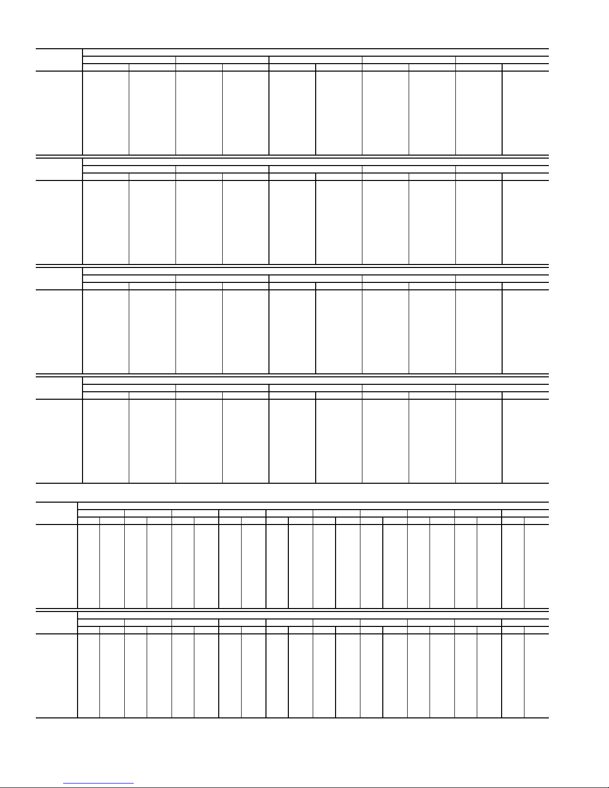
Table 19 — Fan Performance — 50AJ,AK051 Units
AIRFLOW
(Cfm)
10,000 397 2.69 461 3.31 516 3.96 564 4.63 608 5.33
12,000 450 4.03 509 4.71 560 5.41 605 6.12 647 6.86
13,000 477 4.83 533 5.55 582 6.27 627 7.01 668 7.77
14,000 505 5.74 558 6.49 606 7.24 649 8.01 689 8.79
15,000 533 6.75 584 7.53 630 8.32 672 9.11 711 9.91
16,000 561 7.88 610 8.68 655 9.50 696 10.32 734 11.14
17,000 590 9.12 637 9.95 680 10.79 720 11.64 757 12.49
18,000 619 10.48 664 11.33 706 12.20 744 13.07 781 13.96
19,000 648 11.96 692 12.84 732 13.74 769 14.64 805 15.54
20,000 678 13.57 719 14.47 758 15.40 795 16.32 829 17.25
21,000 707 15.30 748 16.24 785 17.19 821 18.14 854 19.09
22,000 737 17.18 776 18.14 812 19.11 847 20.09 879 21.07
23,000 767 19.20 804 20.18 840 21.17 873 22.17 905 23.18
24,000 797 21.35 833 22.36 867 23.38 900 24.40 931 25.43
25,000 827 23.66 862 24.68 895 25.72 927 26.78 957 27.83
AIRFLOW
(Cfm)
10,000 649 6.06 686 6.82 722 7.60 755 8.40 787 9.23
12,000 686 7.62 723 8.40 757 9.21 790 10.04 821 10.89
13,000 706 8.55 742 9.35 776 10.17 808 11.01 839 11.87
14,000 727 9.59 762 10.40 795 11.24 827 12.09 857 12.96
15,000 748 10.73 782 11.56 815 12.41 846 13.28 876 14.17
16,000 770 11.98 803 12.84 836 13.71 866 14.59 896 15.49
17,000 792 13.35 825 14.23 857 15.12 887 16.02 916 16.94
18,000 815 14.84 847 15.74 878 16.65 908 17.57 937 18.50
19,000 838 16.45 870 17.37 900 18.30 930 19.24 958 20.19
20,000 862 18.19 893 19.13 923 20.08 952 21.04 979 22.01
21,000 886 20.05 917 21.02 946 22.00 974 22.98 1001 23.97
22,000 911 22.06 940 23.05 969 24.04 997 25.05 1024 26.06
23,000 935 24.19 965 25.21 993 26.23 1020 27.25 1046 28.28
24,000 961 26.47 989 27.51 1017 28.55 1044 29.60 1070 30.65
25,000 986 28.89 1014 29.95 1041 31.02 1068 32.09 1093 33.17
AIRFLOW
(Cfm)
10,000 818 10.06 847 10.92 875 11.80 902 12.68 929 13.59
12,000 851 11.75 880 12.63 907 13.53 934 14.45 960 15.38
13,000 868 12.75 897 13.64 924 14.55 951 15.48 976 16.42
14,000 886 13.85 915 14.76 942 15.68 968 16.62 993 17.57
15,000 905 15.07 933 15.99 960 16.92 986 17.87 1011 18.83
16,000 924 16.41 952 17.34 978 18.28 1004 19.25 1029 20.22
17,000 944 17.86 971 18.81 997 19.77 1023 20.74 1047 21.73
18,000 964 19.45 991 20.41 1017 21.38 1042 22.36 1066 23.36
19,000 985 21.15 1011 22.13 1037 23.12 1061 24.11 1085 25.13
20,000 1006 22.99 1032 23.98 1057 24.99 1081 26.00 1105 27.03
21,000 1028 24.97 1053 25.97 1078 26.99 1102 28.02 1126 29.06
22,000 1050 27.08 1075 28.10 1099 29.14 1123 30.18 1146 31.24
23,000 1072 29.32 1097 30.37 1121 31.42 1144 32.48 1167 33.55
24,000 1095 31.71 1119 32.78 1143 33.85 1166 34.93 1189 36.02
25,000 1118 34.25 1142 35.33 1165 36.42 1188 37.52 — —
AIRFLOW
(Cfm)
10,000 954 14.50 979 15.42 1003 16.36 1027 17.30 1050 18.26
12,000 985 16.32 1010 17.28 1033 18.24 1057 19.22 1079 20.22
13,000 1001 17.38 1026 18.35 1049 19.32 1072 20.32 1095 21.32
14,000 1018 18.54 1042 19.52 1066 20.51 1088 21.52 1111 22.53
15,000 1035 19.81 1059 20.81 1082 21.81 1105 22.82 1127 23.85
16,000 1053 21.21 1077 22.21 1100 23.22 1122 24.25 1144 25.29
17,000 1071 22.73 1095 23.74 1117 24.76 1140 25.80 1161 26.85
18,000 1090 24.37 1113 25.40 1136 26.43 1158 27.48 1179 28.54
19,000 1109 26.15 1132 27.19 1154 28.24 1176 29.29 1197 30.36
20,000 1128 28.06 1151 29.11 1173 30.17 1195 31.24 — —
21,000 1148 30.11 1171 31.17 1193 32.25 — — — —
22,000 1169 32.30 1191 33.38 ——————
23,000 119034.64————————
24,000 ——————————
25,000 ——————————
0.2 0.4 0.6 0.8 1.0
Rpm Bhp Rpm Bhp Rpm Bhp Rpm Bhp Rpm Bhp
1.2 1.4 1.6 1.8 2.0
Rpm Bhp Rpm Bhp Rpm Bhp Rpm Bhp Rpm Bhp
2.2 2.4 2.6 2.8 3.0
Rpm Bhp Rpm Bhp Rpm Bhp Rpm Bhp Rpm Bhp
3.2 3.4 3.6 3.8 4.0
Rpm Bhp Rpm Bhp Rpm Bhp Rpm Bhp Rpm Bhp
AVAILABLE EXTERNAL STATIC PRESSURE (in. wg)
AVAILABLE EXTERNAL STATIC PRESSURE (in. wg)
AVAILABLE EXTERNAL STATIC PRESSURE (in. wg)
AVAILABLE EXTERNAL STATIC PRESSURE (in. wg)
Table 20 — Fan Performance — 50AJ,AK,A2,A3060 Units
AIRFLOW
(Cfm)
12,000 450 4.02 509 4.71 560 5.41 605 6.12 647 6.86 686 7.62 723 8.40 757 9.21 790 10.04 821 10.89
14,000 505 5.74 558 6.49 606 7.24 649 8.01 689 8.79 727 9.59 762 10.40 795 11.24 827 12.09 857 12.96
15,000 533 6.75 584 7.53 630 8.32 672 9.11 711 9.91 748 10.73 782 11.56 815 12.41 846 13.28 876 14.17
16,000 561 7.88 610 8.68 655 9.50 696 10.32 734 11.14 770 11.98 803 12.84 836 13.71 866 14.59 896 15.49
17,000 590 9.12 637 9.95 680 10.79 720 11.64 757 12.49 792 13.35 825 14.23 857 15.12 887 16.02 916 16.94
18,000 619 10.48 664 11.33 706 12.20 744 13.07 781 13.96 815 14.84 847 15.74 878 16.65 908 17.57 937 18.50
19,000 648 11.96 692 12.84 732 13.74 769 14.64 805 15.54 838 16.45 870 17.37 900 18.30 930 19.24 958 20.19
20,000 678 13.57 719 14.47 758 15.40 795 16.32 829 17.25 862 18.19 893 19.13 923 20.08 952 21.04 979 22.01
21,000 707 15.30 748 16.24 785 17.19 821 18.14 854 19.09 886 20.05 917 21.02 946 22.00 974 22.98 1001 23.97
22,000 737 17.18 776 18.14 812 19.11 847 20.09 879 21.07 911 22.06 940 23.05 969 24.04 997 25.05 1024 26.06
23,000 767 19.20 804 20.18 840 21.17 873 22.17 905 23.18 935 24.19 965 25.21 993 26.23 1020 27.25 1046 28.28
24,000 797 21.35 833 22.36 867 23.38 900 24.40 931 25.43 961 26.47 989 27.51 1017 28.55 1044 29.60 1070 30.65
25,000 827 23.66 862 24.68 895 25.72 927 26.78 957 27.83 986 28.89 1014 29.95 1041 31.02 1068 32.09 1093 33.17
26,000 857 26.11 891 27.16 923 28.23 954 29.30 984 30.38 1012 31.46 1040 32.55 1066 33.64 1092 34.73 1117 35.83
27,000 888 28.72 920 29.79 952 30.88 982 31.97 1011 33.08 1038 34.19 1065 35.29 1091 36.40 1117 37.52 1141 38.64
AIRFLOW
(Cfm)
12,000 851 11.75 880 12.63 907 13.53 934 14.45 960 15.38 985 16.32 1010 17.28 1033 18.24 1057 19.22 1079 20.22
14,000 886 13.85 915 14.76 942 15.68 968 16.62 993 17.57 1018 18.54 1042 19.52 1066 20.51 1088 21.52 1111 22.53
15,000 905 15.07 933 15.99 960 16.92 986 17.87 1011 18.83 1035 19.81 1059 20.81 1082 21.81 1105 22.82 1127 23.85
16,000 924 16.41 952 17.34 978 18.28 1004 19.25 1029 20.22 1053 21.21 1077 22.21 1100 23.22 1122 24.25 1144 25.29
17,000 944 17.86 971 18.81 997 19.77 1023 20.74 1047 21.73 1071 22.73 1095 23.74 1117 24.76 1140 25.80 1161 26.85
18,000 964 19.45 991 20.41 1017 21.38 1042 22.36 1066 23.36 1090 24.37 1113 25.40 1136 26.43 1158 27.48 1179 28.54
19,000 985 21.15 1011 22.13 1037 23.12 1061 24.11 1085 25.13 1109 26.15 1132 27.19 1154 28.24 1176 29.29 1197 30.36
20,000 1006 22.99 1032 23.98 1057 24.99 1081 26.00 1105 27.03 1128 28.06 1151 29.11 1173 30.17 1195 31.24 — —
21,000 1028 24.97 1053 25.97 1078 26.99 1102 28.02 1126 29.06 1148 30.11 1171 31.17 1193 32.25 ————
22,000 1050 27.08 1075 28.10 1099 29.14 1123 30.18 1146 31.24 1169 32.30 1191 33.38 — —————
23,000 1072 29.32 1097 30.37 1121 31.42 1144 32.48 1167 33.55 1190 34.64 — — — —————
24,000 1095 31.71 1119 32.78 1143 33.85 1166 34.93 1189 36.02 ——————————
25,000 1118 34.25 1142 35.33 1165 36.42 1188 37.52 — — ——————————
26,000 1141 36.93 1165 38.04 1188 39.15 ——————————————
27,000 1165 39.76 1188 40.89 — ———————————————
0.2 0.4 0.6 0.8 1.0 1.2 1.4 1.6 1.8 2.0
Rpm Bhp Rpm Bhp Rpm Bhp Rpm Bhp Rpm Bhp Rpm Bhp Rpm Bhp Rpm Bhp Rpm Bhp Rpm Bhp
2.2 2.4 2.6 2.8 3.0 3.2 3.4 3.6 3.8 4.0
Rpm Bhp Rpm Bhp Rpm Bhp Rpm Bhp Rpm Bhp Rpm Bhp Rpm Bhp Rpm Bhp Rpm Bhp Rpm Bhp
AVAILABLE E XTERNAL STATIC PRESSURE (in. wg)
AVAILABLE E XTERNAL STATIC PRESSURE (in. wg)
16
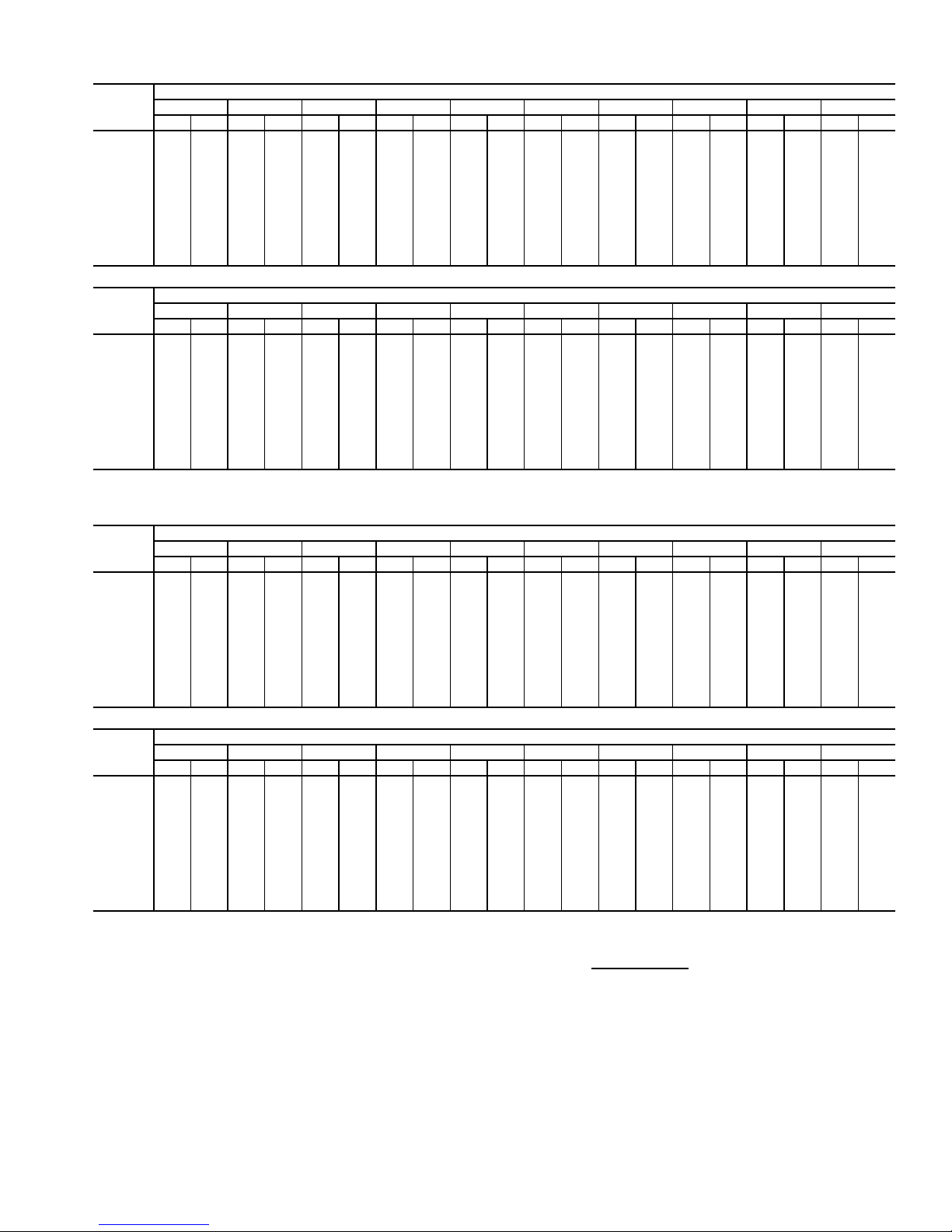
Table 21 — Fan Performance — 48AW,AY020,025 and 48A4,A5020 Units
AIRFLOW
(CFM)
4,000 339 0.71 414 0.97 478 1.25 534 1.54 585 1.84 631 2.14 674 2.44 714 2.75 751 3.06 787 3.37
5,000 384 1.10 452 1.37 510 1.66 563 1.96 611 2.28 656 2.60 698 2.93 738 3.27 775 3.60 811 3.94
6,000 433 1.61 494 1.89 548 2.19 597 2.51 643 2.84 686 3.18 726 3.52 764 3.88 800 4.23 835 4.60
7,000 484 2.27 540 2.56 590 2.87 636 3.19 679 3.53 719 3.88 757 4.24 794 4.61 829 4.98 863 5.36
7,500 511 2.66 563 2.95 612 3.26 656 3.59 698 3.94 737 4.29 775 4.66 810 5.03 845 5.41 877 5.79
8,000 538 3.09 588 3.38 634 3.70 678 4.03 718 4.38 756 4.74 793 5.11 827 5.49 861 5.87 893 6.26
9,000 593 4.07 639 4.37 682 4.69 722 5.03 760 5.39 796 5.76 831 6.13 864 6.52 896 6.91 927 7.32
10,000 649 5.23 691 5.54 731 5.87 769 6.21 805 6.58 839 6.95 872 7.34 904 7.73 934 8.13 964 8.54
11,000 706 6.58 744 6.89 782 7.23 817 7.58 851 7.95 884 8.33 915 8.72 945 9.12 975 9.53 1003 9.95
12,000 763 8.12 799 8.45 834 8.79 867 9.14 899 9.52 930 9.90 960 10.30 989 10.71 1017 11.12 1045 11.54
12,500 792 8.97 827 9.30 860 9.64 893 10.00 924 10.38 954 10.77 983 11.16 1012 11.57 1039 11.99 1066 12.42
13,000 821 9.87 855 10.20 887 10.55 918 10.91 949 11.29 978 11.68 1007 12.08 1034 12.49 1062 12.92 1088 13.35
AIRFLOW
(CFM)
4,000 820 3.68 852 3.99 883 4.30 912 4.62 940 4.93 967 5.25 993 5.57 1019 5.89 1043 6.21 1067 6.53
5,000 844 4.28 877 4.63 907 4.97 937 5.31 966 5.66 993 6.01 1020 6.35 1046 6.70 1071 7.05 1095 7.40
6,000 869 4.96 901 5.33 931 5.70 961 6.07 990 6.44 1017 6.81 1044 7.19 1070 7.57 1096 7.94 1121 8.32
7,000 895 5.74 926 6.13 956 6.52 986 6.91 1014 7.30 1042 7.70 1068 8.10 1094 8.50 1120 8.90 1145 9.30
7,500 909 6.18 940 6.57 970 6.97 999 7.37 1027 7.78 1054 8.18 1081 8.59 1107 9.00 1132 9.41 1157 9.82
8,000 925 6.66 955 7.06 984 7.46 1013 7.87 1040 8.28 1067 8.69 1094 9.11 1119 9.53 1144 9.95 1169 10.37
9,000 957 7.72 986 8.13 1015 8.55 1042 8.97 1069 9.39 1096 9.82 1121 10.25 1146 10.69 1171 11.12 1195 11.56
10,000 993 8.96 1021 9.38 1048 9.80 1075 10.23 1101 10.67 1126 11.11 1151 11.55 1176 12.00 1200 12.45 — —
11,000 1031 10.37 1058 10.80 1084 11.23 1110 11.67 1135 12.12 1160 12.56 1184 13.02 — — — — — —
12,000 1071 11.97 1097 12.41 1123 12.85 1148 13.30 1172 13.75 1196 14.21 — — — — — — — —
12,500 1092 12.85 1118 13.29 1143 13.74 1167 14.19 1191 14.64 — — — — — — — — — —
13,000 1113 13.78 1139 14.22 1163 14.67 — — ————————————
0.2 0.4 0.6 0.8 1.0 1.2 1.4 1.6 1.8 2.0
Rpm Bhp Rpm Bhp Rpm Bhp Rpm Bhp Rpm Bhp Rpm Bhp Rpm Bhp Rpm Bhp Rpm Bhp Rpm Bhp
2.2 2.4 2.6 2.8 3.0 3.2 3.4 3.6 3.8 4.0
Rpm Bhp Rpm Bhp Rpm Bhp Rpm Bhp Rpm Bhp Rpm Bhp Rpm Bhp Rpm Bhp Rpm Bhp Rpm Bhp
AVAILABLE EXTERNAL STATIC PRESSURE (in. wg)
AVAILABLE EXTERNAL STATIC PRESSURE (in. wg)
Table 22 — Fan Performance — 48AW,AY027,030 and 48A4,A5025-030 Units
AIRFLOW
(CFM)
4,000 342 0.72 417 0.98 480 1.26 536 1.55 587 1.85 633 2.15 676 2.45 715 2.76 753 3.07 788 3.38
5,000 389 1.11 456 1.38 514 1.68 566 1.98 614 2.30 659 2.62 701 2.95 740 3.29 777 3.62 813 3.96
6,000 439 1.64 499 1.92 553 2.22 602 2.54 647 2.87 689 3.21 730 3.56 768 3.91 804 4.27 838 4.63
7,000 492 2.31 546 2.60 596 2.91 641 3.24 684 3.58 724 3.93 762 4.29 798 4.66 833 5.03 867 5.41
8,000 546 3.14 596 3.43 642 3.75 684 4.09 724 4.44 762 4.80 798 5.17 833 5.55 866 5.93 898 6.32
9,000 602 4.13 647 4.43 690 4.76 730 5.10 768 5.46 803 5.83 838 6.21 871 6.60 903 7.00 933 7.40
10,000 659 5.31 701 5.62 740 5.95 777 6.30 813 6.67 847 7.04 880 7.43 911 7.83 942 8.23 971 8.64
11,000 717 6.67 755 6.99 792 7.33 827 7.68 860 8.06 893 8.44 924 8.83 954 9.24 983 9.65 1011 10.07
12,000 775 8.23 811 8.56 845 8.90 878 9.27 909 9.64 940 10.03 970 10.43 999 10.84 1026 11.26 1054 11.69
13,000 834 9.99 867 10.33 899 10.68 930 11.05 960 11.44 989 11.83 1017 12.24 1045 12.65 1072 13.08 1098 13.51
14,000 893 11.97 924 12.32 954 12.68 983 13.06 1012 13.44 1039 13.85 1066 14.26 1093 14.68 1118 15.11 1143 15.54
15,000 953 14.17 982 14.53 1010 14.90 1037 15.28 1064 15.68 1091 16.08 1116 16.50 1142 16.93 1166 17.36 1190 17.80
0.2 0.4 0.6 0.8 1.0 1.2 1.4 1.6 1.8 2.0
Rpm Bhp Rpm Bhp Rpm Bhp Rpm Bhp Rpm Bhp Rpm Bhp Rpm Bhp Rpm Bhp Rpm Bhp Rpm Bhp
AVAILABLE EXTERNAL STATIC PRESSURE (in. wg)
AIRFLOW
(CFM)
4,000 821 3.69 853 4.00 884 4.31 913 4.63 941 4.95 968 5.26 994 5.58 1020 5.90 1044 6.22 1068 6.55
5,000 846 4.31 879 4.65 909 4.99 939 5.34 968 5.68 995 6.03 1022 6.38 1048 6.73 1073 7.08 1097 7.43
6,000 872 5.00 903 5.36 934 5.73 964 6.10 992 6.48 1020 6.85 1047 7.22 1073 7.60 1098 7.98 1123 8.36
7,000 899 5.79 930 6.18 960 6.57 989 6.96 1018 7.36 1045 7.75 1072 8.15 1098 8.55 1123 8.95 1148 9.35
8,000 930 6.72 960 7.12 989 7.53 1017 7.94 1045 8.35 1072 8.76 1098 9.18 1124 9.60 1148 10.02 1173 10.44
9,000 963 7.80 992 8.22 1020 8.63 1048 9.06 1075 9.48 1101 9.91 1126 10.34 1151 10.78 1176 11.21 1200 11.65
10,000 1000 9.06 1028 9.48 1055 9.91 1081 10.34 1107 10.77 1133 11.22 1157 11.66 1182 12.11 — — — —
11,000 1039 10.49 1066 10.92 1092 11.36 1117 11.80 1142 12.24 1167 12.69 1191 13.15 — — — — — —
12,000 1080 12.12 1106 12.56 1131 13.00 1156 13.45 1180 13.90 — — — — — — — — — —
13,000 1123 13.95 1148 14.39 1172 14.84 1196 15.30 ————————————
14,000 116815.99119216.44————————————————
15,000 ————————————————————
LEGEND
Bhp — Brake Horsepower
edb — Entering Dry Bulb
ewb — Entering Wet Bulb
NOTES:
1. Fan performance is based on wet coils, economizer, roof curb, cabinet
losses, and clean 2-in. filters.
2.2 2.4 2.6 2.8 3.0 3.2 3.4 3.6 3.8 4.0
Rpm Bhp Rpm Bhp Rpm Bhp Rpm Bhp Rpm Bhp Rpm Bhp Rpm Bhp Rpm Bhp Rpm Bhp Rpm Bhp
AVAILABLE EXTERNAL STATIC PRESSURE (in. wg)
2. Conversion — Bhp to watts:
Watts =
3. Variable air volume units will operate down to 70 cfm/ton. Performance at
70 cfm/ton is limited to unloaded operation and may be additionally limited
by edb and ewb conditions.
Bhp x 746
Motor efficiency
17
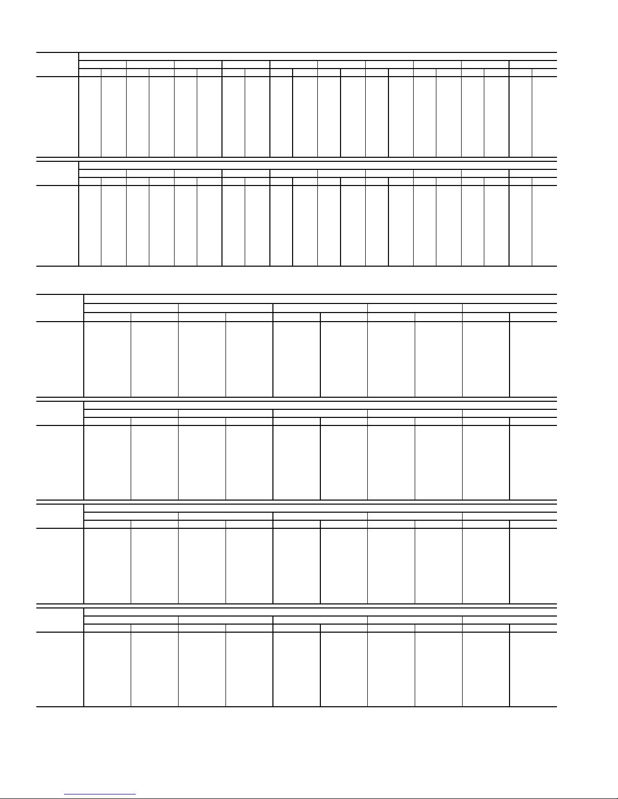
Table 23 — Fan Performance — 48AW,AY,A4,A5035 Units
AIRFLOW
(Cfm)
7,000 553 2.59 602 2.92 648 3.26 691 3.61 732 3.95 770 4.29 807 4.63 842 4.96 875 5.29 907 5.62
8,000 612 3.45 656 3.81 698 4.17 738 4.53 776 4.90 812 5.27 847 5.63 881 6.00 913 6.36 944 6.72
9,000 672 4.47 712 4.86 750 5.24 787 5.62 823 6.01 857 6.39 890 6.78 922 7.17 953 7.56 983 7.95
10,000 733 5.67 769 6.08 805 6.48 839 6.88 872 7.28 904 7.69 935 8.10 966 8.51 995 8.92 1024 9.33
10,500 763 6.33 798 6.75 832 7.17 865 7.58 897 7.99 929 8.40 959 8.82 989 9.24 1017 9.66 1046 10.08
11,000 794 7.04 828 7.47 861 7.90 892 8.32 923 8.74 954 9.16 983 9.59 1012 10.01 1040 10.44 1067 10.87
12,000 855 8.60 887 9.06 918 9.51 948 9.95 977 10.39 1005 10.83 1033 11.27 1060 11.71 1087 12.16 1113 12.60
13,000 917 10.36 947 10.84 976 11.31 1004 11.77 1031 12.23 1058 12.69 1084 13.14 1110 13.60 1135 14.06 1160 14.52
14,000 980 12.32 1008 12.82 1035 13.31 1061 13.79 1087 14.27 1112 14.75 1137 15.22 1161 15.70 1185 16.17 1209 16.65
15,000 1042 14.49 1069 15.01 1094 15.52 1119 16.03 1143 16.53 1167 17.02 1191 17.51 1214 18.01 1237 18.50 1260 18.99
16,000 1105 16.88 1130 17.42 1154 17.96 1178 18.48 1201 19.00 1224 19.51 1246 20.02 1268 20.53 1290 21.04 — —
17,000 116819.49119120.06121420.61123721.16125921.69128122.23————————
17,500 120020.88122221.46124522.03126722.58128823.13——————————
AIRFLOW
(Cfm)
7,000 937 5.94 967 6.26 995 6.57 1022 6.87 1048 7.18 1073 7.48 1098 7.78 1122 8.07 1145 8.36 1168 8.66
8,000 974 7.08 1003 7.43 1031 7.77 1058 8.12 1084 8.46 1109 8.79 1134 9.13 1158 9.46 1181 9.78 1204 10.11
9,000 1012 8.33 1041 8.72 1068 9.10 1094 9.47 1120 9.85 1145 10.22 1169 10.58 1193 10.95 1216 11.31 1239 11.66
10,000 1052 9.74 1080 10.15 1106 10.55 1132 10.96 1157 11.36 1182 11.76 1206 12.16 1229 12.55 1252 12.95 1275 13.34
10,500 1073 10.50 1100 10.92 1126 11.34 1151 11.75 1176 12.17 1201 12.59 1224 13.00 1248 13.41 1271 13.82 1293 14.22
11,000 1094 11.30 1120 11.73 1146 12.16 1171 12.59 1196 13.02 1220 13.45 1243 13.87 1266 14.30 1289 14.72 — —
12,000 113813.05116313.50118813.95121214.40123614.84125915.30128215.74——————
13,000 118414.99120815.45123215.92125516.39127816.85——————————
14,000 123217.13125517.61127818.09——————————————
15,000 128219.48——————————————————
16,000 ————————————————————
17,000 ————————————————————
17,500 ————————————————————
0.20.40.60.81.01.21.41.61.82.0
RpmBhpRpmBhpRpmBhpRpmBhpRpmBhpRpmBhpRpmBhpRpmBhpRpmBhpRpmBhp
2.22.42.62.83.03.23.43.63.84.0
RpmBhpRpmBhpRpmBhpRpmBhpRpmBhpRpmBhpRpmBhpRpmBhpRpmBhpRpmBhp
AVAILABLE EXTERNAL STATIC PRESSURE (in. wg)
AVAILABLE EXTERNAL STATIC PRESSURE (in. wg)
Table 24 — Fan Performance — 48AW,AY036 Units
AIRFLOW
(Cfm)
7,000 475 2.29 527 2.66 576 3.05 622 3.44 666 3.84
8,000 526 3.10 573 3.50 617 3.91 660 4.33 700 4.75
9,000 579 4.08 621 4.51 662 4.95 701 5.39 738 5.83
10,000 633 5.24 671 5.70 709 6.16 744 6.62 779 7.09
11,000 687 6.59 723 7.07 757 7.56 790 8.05 823 8.54
12,000 742 8.15 775 8.65 807 9.17 838 9.68 868 10.20
13,000 797 9.92 827 10.45 857 10.98 887 11.52 915 12.07
14,000 852 11.92 881 12.47 909 13.03 936 13.59 963 14.15
15,000 908 14.15 935 14.72 961 15.31 987 15.89 1013 16.48
16,000 964 16.63 989 17.23 1014 17.83 1039 18.43 1063 19.04
17,000 1021 19.37 1044 19.98 1068 20.60 1091 21.23 1114 21.86
17,500 1049 20.84 1072 21.46 1095 22.09 1117 22.73 1139 23.36
AIRFLOW
(Cfm)
7,000 709 4.25 749 4.68 788 5.11 825 5.55 860 6.00
8,000 740 5.18 778 5.62 814 6.07 850 6.53 884 7.00
9,000 775 6.28 810 6.74 845 7.21 878 7.69 911 8.17
10,000 813 7.57 846 8.05 879 8.53 910 9.03 941 9.53
11,000 854 9.04 885 9.54 916 10.05 945 10.56 974 11.08
12,000 898 10.72 927 11.24 955 11.77 983 12.30 1011 12.84
13,000 943 12.61 970 13.15 997 13.70 1024 14.25 1050 14.81
14,000 990 14.72 1016 15.29 1041 15.86 1066 16.43 1091 17.01
15,000 1038 17.06 1062 17.65 1086 18.25 1110 18.84 1134 19.44
16,000 1086 19.65 1110 20.26 1133 20.88 1156 21.49 1178 22.11
17,000 1136 22.49 1158 23.12 1180 23.76 1202 24.39 1223 25.03
17,500 1161 24.01 1183 24.65 1205 25.30 1226 25.94 1247 26.59
AIRFLOW
(Cfm)
7,000 894 6.46 927 6.92 958 7.38 988 7.85 1017 8.33
8,000 917 7.48 949 7.96 980 8.44 1010 8.93 1039 9.43
9,000 942 8.66 973 9.16 1003 9.66 1033 10.17 1061 10.69
10,000 971 10.03 1001 10.55 1030 11.06 1058 11.59 1086 12.12
11,000 1003 11.60 1031 12.13 1059 12.67 1086 13.21 1112 13.75
12,000 1038 13.38 1065 13.92 1091 14.47 1117 15.03 1142 15.59
13,000 1075 15.37 1101 15.93 1126 16.50 1150 17.07 1175 17.65
14,000 1115 17.59 1139 18.17 1163 18.75 1186 19.34 1210 19.94
15,000 1157 20.04 1180 20.64 1202 21.24 1225 21.85 1247 22.46
16,000 1200 22.73 1222 23.35 1243 23.97 1265 24.60 1286 25.23
17,000 1245 25.67 1266 26.32 1286 26.96 — — — —
17,500 126727.24128827.89——————
AIRFLOW
(Cfm)
7,000 1046 8.81 1073 9.29 1099 9.78 1125 10.27 1150 10.76
8,000 1067 9.93 1094 10.44 1121 10.95 1147 11.46 1172 11.98
9,000 1089 11.21 1116 11.73 1142 12.26 1168 12.80 1193 13.33
10,000 1113 12.66 1139 13.20 1165 13.75 1190 14.30 1215 14.86
11,000 1139 14.31 1164 14.86 1189 15.43 1214 15.99 1238 16.56
12,000 1167 16.16 1192 16.73 1216 17.31 1240 17.89 1264 18.48
13,000 1199 18.23 1222 18.82 1246 19.41 1269 20.00 1291 20.61
14,000 1232 20.53 1255 21.14 1277 21.74 1300 22.35 — —
15,000 126923.07129023.69——————
16,000 ——————————
17,000 ——————————
17,500 ——————————
See legend on page 17.
0.2 0.4 0.6 0.8 1.0
Rpm Bhp Rpm Bhp Rpm Bhp Rpm Bhp Rpm Bhp
1.2 1.4 1.6 1.8 2.0
Rpm Bhp Rpm Bhp Rpm Bhp Rpm Bhp Rpm Bhp
2.2 2.4 2.6 2.8 3.0
Rpm Bhp Rpm Bhp Rpm Bhp Rpm Bhp Rpm Bhp
3.2 3.4 3.6 3.8 4.0
Rpm Bhp Rpm Bhp Rpm Bhp Rpm Bhp Rpm Bhp
AVAILABLE EXTERNAL STATIC PRESSURE (in. wg)
AVAILABLE EXTERNAL STATIC PRESSURE (in. wg)
AVAILABLE EXTERNAL STATIC PRESSURE (in. wg)
AVAILABLE EXTERNAL STATIC PRESSURE (in. wg)
18
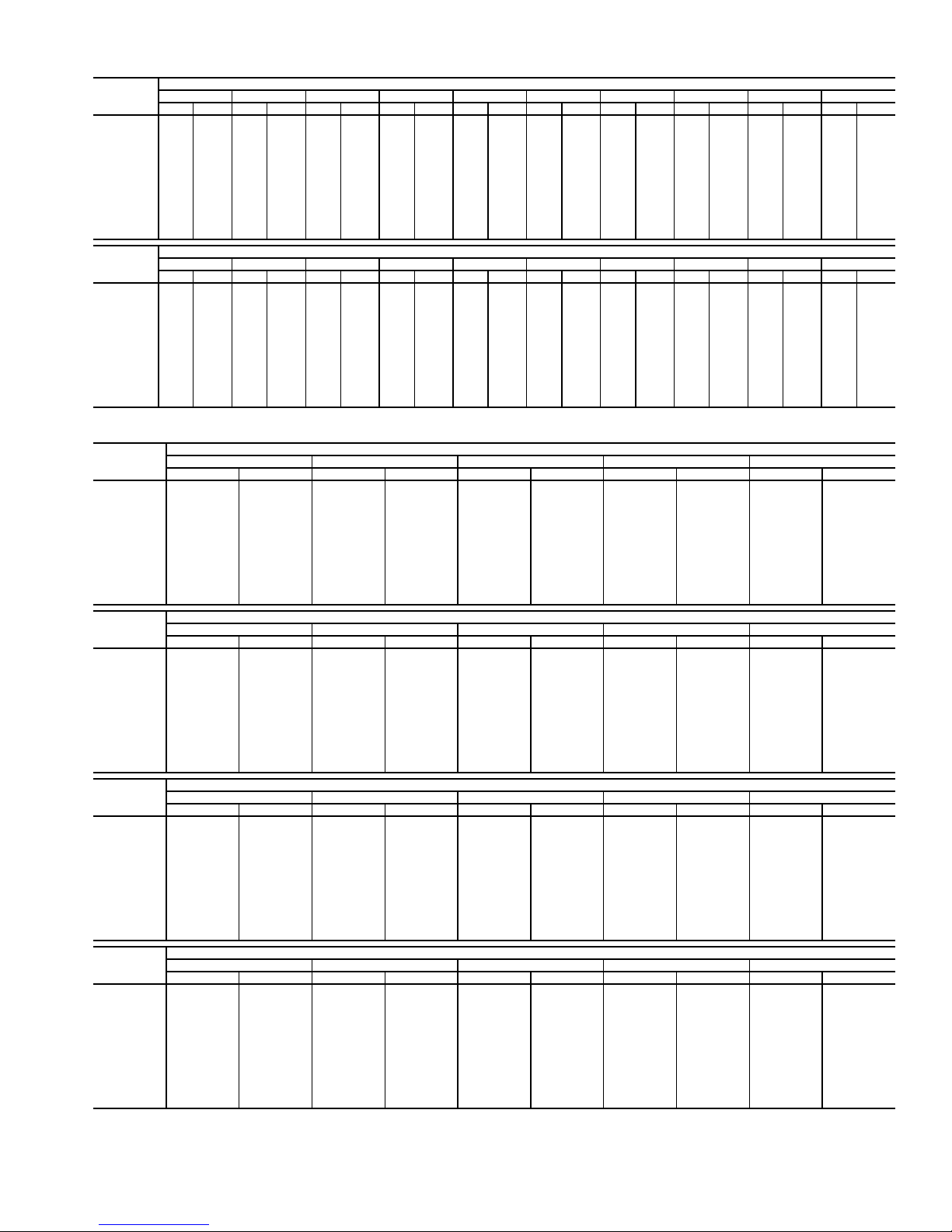
Table 25 — Fan Performance — 48AW,AY,A4,A5040 Units
AIRFLOW
(Cfm)
8,000 526 3.10 573 3.50 617 3.91 660 4.33 700 4.75 740 5.18 778 5.62 814 6.07 850 6.53 884 7.00
9,000 579 4.08 621 4.51 662 4.95 701 5.39 738 5.83 775 6.28 810 6.74 845 7.21 878 7.69 911 8.17
10,000 633 5.24 671 5.70 709 6.16 744 6.62 779 7.09 813 7.57 846 8.05 879 8.53 910 9.03 941 9.53
11,000 687 6.59 723 7.07 757 7.56 790 8.05 823 8.54 854 9.04 885 9.54 916 10.05 945 10.56 974 11.08
12,000 742 8.15 775 8.65 807 9.17 838 9.68 868 10.20 898 10.72 927 11.24 955 11.77 983 12.30 1011 12.84
13,000 797 9.92 827 10.45 857 10.98 887 11.52 915 12.07 943 12.61 970 13.15 997 13.70 1024 14.25 1050 14.81
14,000 852 11.92 881 12.47 909 13.03 936 13.59 963 14.15 990 14.72 1016 15.29 1041 15.86 1066 16.43 1091 17.01
15,000 908 1 4.15 935 14.72 961 15.31 987 15.89 1013 16.48 1038 17.06 1062 17.65 1086 18.25 1110 18.84 1134 19.44
16,000 964 16.63 989 17.23 1014 17.83 1039 18.43 1063 19.04 1086 19.65 1110 20.26 1133 20.88 1156 21.49 1178 22.11
17,000 1021 19.37 1044 19.98 1068 20.60 1091 21.23 1114 21.86 1136 22.49 1158 23.12 1180 23.76 1202 24.39 1223 25.03
18,000 1077 22.37 1099 23.01 1122 23.64 1144 24.29 1165 24.94 1187 25.59 1208 26.25 1229 26.90 1250 27.56 1270 28.22
19,000 113325.65115526.30117626.96119727.62121728.29123828.96————————
20,000 119029.21——————————————————
AIRFLOW
(Cfm)
8,000 917 7.48 949 7.96 980 8.44 1010 8.94 1039 9.43 1067 9.93 1094 10.44 1121 10.95 1147 11.46 1172 11.98
9,000 942 8.66 973 9.16 1003 9.66 1033 10.17 1061 10.69 1089 11.21 1116 11.73 1142 12.26 1168 12.80 1193 13.33
10,000 971 1 0.03 1001 10.55 1030 11.06 1058 11.59 1086 12.12 1113 12.66 1139 13.20 1165 13.75 1190 14.30 1215 14.86
11,000 1003 11.60 1031 12.13 1059 12.67 1086 13.21 1112 13.75 1139 14.31 1164 14.86 1189 15.43 1214 15.99 1238 16.56
12,000 1038 13.38 1065 13.92 1091 14.47 1117 15.03 1142 15.59 1167 16.16 1192 16.73 1216 17.31 1240 17.89 1264 18.48
13,000 1075 15.37 1101 15.93 1126 16.50 1150 17.07 1175 17.65 1199 18.23 1222 18.82 1246 19.41 1269 20.00 1291 20.61
14,000 1115 17.59 1139 18.17 1163 18.75 1186 19.34 1210 19.94 1232 20.53 1255 21.14 1277 21.74 1300 22.35 — —
15,000 115720.04118020.64120221.24122521.85124722.46126923.07129023.69——————
16,000 120022.73122223.35124323.97126524.60128625.23——————————
17,000 124525.67126626.32128626.96——————————————
18,000 129028.88——————————————————
19,000 ————————————————————
20,000 ————————————————————
0.20.40.60.81.01.21.41.61.82.0
Rpm Bhp Rpm Bhp Rpm Bhp Rpm Bhp Rpm Bhp Rpm Bhp Rpm Bhp Rpm Bhp Rpm Bhp Rpm Bhp
2.22.42.62.83.03.23.43.63.84.0
Rpm Bhp Rpm Bhp Rpm Bhp Rpm Bhp Rpm Bhp Rpm Bhp Rpm Bhp Rpm Bhp Rpm Bhp Rpm Bhp
AVAILABLE EXTERNAL STATIC PRESSURE (in. wg)
AVAILABLE EXTERNAL STATIC PRESSURE (in. wg)
Table 26 — Fan Performance — 48AW,AY041 Units
AIRFLOW
(Cfm)
8,000 526 3.10 573 3.50 617 3.91 660 4.33 700 4.75
9,000 579 4.08 621 4.51 662 4.95 701 5.39 738 5.83
10,000 633 5.24 671 5.70 709 6.16 744 6.62 779 7.09
11,000 687 6.59 723 7.07 757 7.56 790 8.05 823 8.54
12,000 742 8.15 775 8.65 807 9.17 838 9.68 868 10.20
13,000 797 9.92 827 10.45 857 10.98 887 11.52 915 12.07
14,000 852 11.92 881 12.47 909 13.03 936 13.59 963 14.15
15,000 908 14.15 935 14.72 961 15.31 987 15.89 1013 16.48
16,000 964 16.63 989 17.23 1014 17.83 1039 18.43 1063 19.04
17,000 1021 19.37 1044 19.98 1068 20.60 1091 21.23 1114 21.86
18,000 1077 22.37 1099 23.01 1122 23.64 1144 24.29 1165 24.94
19,000 1133 25.65 1155 26.30 1176 26.96 1197 27.62 1217 28.29
20,000 119029.21————————
AIRFLOW
(Cfm)
8,000 740 5.18 778 5.62 814 6.07 850 6.53 884 7.00
9,000 775 6.28 810 6.74 845 7.21 878 7.69 911 8.17
10,000 813 7.57 846 8.05 879 8.53 910 9.03 941 9.53
11,000 854 9.04 885 9.54 916 10.05 945 10.56 974 11.08
12,000 898 10.72 927 11.24 955 11.77 983 12.30 1011 12.84
13,000 943 12.61 970 13.15 997 13.70 1024 14.25 1050 14.81
14,000 990 14.72 1016 15.29 1041 15.86 1066 16.43 1091 17.01
15,000 1038 17.06 1062 17.65 1086 18.25 1110 18.84 1134 19.44
16,000 1086 19.65 1110 20.26 1133 20.88 1156 21.49 1178 22.11
17,000 1136 22.49 1158 23.12 1180 23.76 1202 24.39 1223 25.03
18,000 1187 25.59 1208 26.25 1229 26.90 1250 27.56 1270 28.22
19,000 123828.96————————
20,000 ——————————
AIRFLOW
(Cfm)
8,000 917 7.48 949 7.96 980 8.44 1010 8.94 1039 9.43
9,000 942 8.66 973 9.16 1003 9.66 1033 10.17 1061 10.69
10,000 971 10.03 1001 10.55 1030 11.06 1058 11.59 1086 12.12
11,000 1003 11.60 1031 12.13 1059 12.67 1086 13.21 1112 13.75
12,000 1038 13.38 1065 13.92 1091 14.47 1117 15.03 1142 15.59
13,000 1075 15.37 1101 15.93 1126 16.50 1150 17.07 1175 17.65
14,000 1115 17.59 1139 18.17 1163 18.75 1186 19.34 1210 19.94
15,000 1157 20.04 1180 20.64 1202 21.24 1225 21.85 1247 22.46
16,000 1200 22.73 1222 23.35 1243 23.97 1265 24.60 1286 25.23
17,000 1245 25.67 1266 26.32 1286 26.96 — — — —
18,000 129028.88————————
19,000 ——————————
20,000 ——————————
AIRFLOW
(Cfm)
8,000 1067 9.93 1094 10.44 1121 10.95 1147 11.46 1172 11.98
9,000 1089 11.21 1116 11.73 1142 12.26 1168 12.80 1193 13.33
10,000 1113 12.66 1139 13.20 1165 13.75 1190 14.30 1215 14.86
11,000 1139 14.31 1164 14.86 1189 15.43 1214 15.99 1238 16.56
12,000 1167 16.16 1192 16.73 1216 17.31 1240 17.89 1264 18.48
13,000 1199 18.23 1222 18.82 1246 19.41 1269 20.00 1291 20.61
14,000 1232 20.53 1255 21.14 1277 21.74 1300 22.35 — —
15,000 126923.07129023.69——————
16,000 ——————————
17,000 ——————————
18,000 ——————————
19,000 ——————————
20,000 ——————————
See legend on page 17.
0.2 0.4 0.6 0.8 1.0
Rpm Bhp Rpm Bhp Rpm Bhp Rpm Bhp Rpm Bhp
1.2 1.4 1.6 1.8 2.0
Rpm Bhp Rpm Bhp Rpm Bhp Rpm Bhp Rpm Bhp
2.2 2.4 2.6 2.8 3.0
Rpm Bhp Rpm Bhp Rpm Bhp Rpm Bhp Rpm Bhp
3.2 3.4 3.6 3.8 4.0
Rpm Bhp Rpm Bhp Rpm Bhp Rpm Bhp Rpm Bhp
AVAILABLE EXTERNAL STATIC PRESSURE (in. wg)
AVAILABLE EXTERNAL STATIC PRESSURE (in. wg)
AVAILABLE EXTERNAL STATIC PRESSURE (in. wg)
AVAILABLE EXTERNAL STATIC PRESSURE (in. wg)
19

Table 27 — Fan Performance — 48AW,AY,A4,A5050 Units
AIRFLOW
(Cfm)
8,000 536 3.18 582 3.58 626 3.99 668 4.41 708 4.83 747 5.27 785 5.71 821 6.16 857 6.63 891 7.09
9,000 588 4.17 630 4.60 670 5.04 709 5.48 746 5.93 782 6.38 818 6.84 852 7.31 885 7.79 918 8.28
10,000 642 5.35 680 5.80 717 6.27 753 6.73 787 7.20 821 7.68 854 8.16 886 8.65 917 9.14 948 9.65
11,000 696 6.72 732 7.20 766 7.69 799 8.18 831 8.67 863 9.17 893 9.68 923 10.18 953 10.70 982 11.21
12,000 751 8.29 784 8.80 816 9.32 847 9.83 877 10.35 906 10.87 935 11.40 964 11.92 991 12.46 1019 12.99
13,000 807 10.09 837 10.62 867 11.16 896 11.70 924 12.24 952 12.78 979 13.33 1006 13.88 1032 14.43 1058 14.99
14,000 863 12.12 891 12.67 919 13.23 946 13.79 973 14.36 999 14.92 1025 15.49 1050 16.06 1075 16.64 1100 17.21
15,000 919 14.38 946 14.96 972 15.54 997 16.12 1023 16.71 1047 17.30 1072 17.89 1096 18.48 1120 19.08 1143 19.68
16,000 975 16.90 1000 17.49 1025 18.09 1049 18.70 1073 19.31 1097 19.92 1120 20.53 1143 21.15 1165 21.76 1188 22.38
17,000 1032 19.67 1056 20.29 1079 20.91 1102 21.54 1125 22.17 1147 22.80 1169 23.44 1191 24.07 1213 24.71 1234 25.35
18,000 1089 22.71 1111 23.35 1134 23.99 1155 24.64 1177 25.29 1198 25.95 1219 26.60 1240 27.26 1261 27.92 1281 28.58
19,000 1146 26.04 1167 26.69 1188 27.35 1209 28.02 1230 28.69 1250 29.37 1270 30.04 1290 30.72 ————
20,000 1203 29.65 1224 30.32 1244 31.00 1263 31.69 1283 32.38 ——————————
AIRFLOW
(Cfm)
8,000 923 7.57 955 8.05 986 8.54 1016 9.03 1045 9.53 1073 10.03 1100 10.54 1126 11.05 1152 11.56 1177 12.08
9,000 949 8.77 980 9.27 1010 9.77 1039 10.28 1067 10.80 1095 11.32 1122 11.85 1148 12.38 1174 12.91 1199 13.45
10,000 978 10.15 1008 10.67 1036 11.19 1064 11.72 1092 12.25 1119 12.79 1145 13.33 1171 13.88 1196 14.43 1221 14.99
11,000 1010 11.74 1038 12.27 1066 12.81 1093 13.35 1119 13.90 1145 14.45 1171 15.01 1196 15.57 1220 16.14 1245 16.72
12,000 1046 13.53 1072 14.08 1098 14.63 1124 15.19 1149 15.76 1174 16.32 1199 16.90 1223 17.48 1247 18.06 1270 18.65
13,000 1084 15.55 1109 16.11 1134 16.68 1158 17.26 1182 17.84 1206 18.42 1230 19.01 1253 19.60 1276 20.20 1299 20.80
14,000 1124 17.79 1148 18.38 1171 18.97 1195 19.55 1218 20.15 1241 20.75 1263 21.35 1285 21.96 ————
15,000 1166 20.27 1189 20.88 1211 21.49 1234 22.09 1256 22.71 1277 23.32 1299 23.94 — —————
16,000 1210 23.00 1231 23.62 1253 24.25 1274 24.88 1295 25.51 ——————————
17,000 1255 25.99 1276 26.63 1296 27.27 ——————————————
18,000 ————————————————————
19,000 ————————————————————
20,000 ————————————————————
0.2 0.4 0.6 0.8 1.0 1.2 1.4 1.6 1.8 2.0
Rpm Bhp Rpm Bhp Rpm Bhp Rpm Bhp Rpm Bhp Rpm Bhp Rpm Bhp Rpm Bhp Rpm Bhp Rpm Bhp
2.2 2.4 2.6 2.8 3.0 3.2 3.4 3.6 3.8 4.0
Rpm Bhp Rpm Bhp Rpm Bhp Rpm Bhp Rpm Bhp Rpm Bhp Rpm Bhp Rpm Bhp Rpm Bhp Rpm Bhp
AVAILABLE E XTERNAL STATIC PRESSURE (in. wg)
AVAILABLE E XTERNAL STATIC PRESSURE (in. wg)
Table 28 — Fan Performance — 48AW,AY051 Units
AIRFLOW
(Cfm)
10,000 450 3.19 509 3.86 561 4.58 608 5.34 651 6.14
12,000 516 4.81 569 5.54 617 6.30 660 7.10 701 7.93
13,000 550 5.80 600 6.56 646 7.34 688 8.15 727 9.00
14,000 584 6.90 632 7.69 676 8.50 716 9.33 754 10.20
15,000 619 8.13 664 8.96 706 9.79 745 10.65 782 11.53
16,000 654 9.49 697 10.36 737 11.22 775 12.10 811 13.00
17,000 689 10.99 730 11.90 769 12.79 806 13.69 840 14.61
18,000 725 12.64 764 13.58 801 14.51 837 15.43 870 16.38
19,000 760 14.43 798 15.41 834 16.37 868 17.32 900 18.29
20,000 796 16.37 833 17.39 867 18.39 900 19.37 931 20.36
21,000 832 18.47 867 19.54 901 20.56 932 21.57 963 22.59
22,000 869 20.74 902 21.84 934 22.90 965 23.94 995 24.98
23,000 905 23.17 937 24.31 968 25.40 998 26.48 1027 27.55
24,000 942 25.78 973 26.95 1003 28.08 1032 29.18 1059 30.28
25,000 978 28.56 1008 29.77 1037 30.93 1065 32.07 1092 33.20
AIRFLOW
(Cfm)
10,000 691 6.96 728 7.80 764 8.66 797 9.53 829 10.42
12,000 739 8.79 774 9.68 808 10.59 841 11.52 872 12.46
13,000 764 9.88 799 10.79 832 11.72 864 12.67 894 13.64
14,000 790 11.10 824 12.02 857 12.97 888 13.94 917 14.92
15,000 817 12.44 850 13.38 882 14.35 912 15.33 941 16.34
16,000 845 13.93 877 14.88 908 15.86 938 16.86 966 17.88
17,000 873 15.56 904 16.53 935 17.52 964 18.54 992 19.58
18,000 902 17.34 933 18.32 962 19.33 990 20.36 1018 21.41
19,000 932 19.27 961 20.27 990 21.29 1018 22.34 1045 23.40
20,000 962 21.36 991 22.38 1019 23.42 1046 24.48 1072 25.56
21,000 992 23.61 1020 24.65 1048 25.71 1074 26.78 1100 27.87
22,000 1023 26.03 1051 27.09 1077 28.17 1103 29.26 1129 30.36
23,000 1055 28.62 1081 29.70 1107 30.79 1133 31.90 1157 33.02
24,000 1086 31.38 1113 32.48 1138 33.59 1163 34.72 1187 35.86
25,000 1119 34.32 1144 35.44 1169 36.58 1193 37.72 — —
AIRFLOW
(Cfm)
10,000 860 11.31 890 12.21 918 13.11 946 14.02 973 14.94
12,000 901 13.42 930 14.38 958 15.36 985 16.34 1011 17.33
13,000 923 14.62 952 15.61 979 16.61 1006 17.62 1031 18.64
14,000 946 15.92 974 16.94 1001 17.97 1027 19.01 1052 20.06
15,000 970 17.36 997 18.40 1024 19.45 1049 20.51 1074 21.58
16,000 994 18.93 1021 19.98 1047 21.05 1072 22.14 1097 23.23
17,000 1019 20.63 1045 21.70 1071 22.79 1096 23.89 1120 25.01
18,000 1045 22.48 1070 23.57 1096 24.67 1120 25.79 1144 26.93
19,000 1071 24.49 1096 25.59 1121 26.71 1145 27.84 1169 28.99
20,000 1098 26.66 1123 27.77 1147 28.90 1171 30.05 1194 31.21
21,000 1125 28.99 1150 30.12 1173 31.26 1197 32.42 — —
22,000 1153 31.49 1177 32.63 ——————
23,000 118134.16————————
24,000 ——-————————
25,000 ———-———————
AIRFLOW
(Cfm)
10,000 998 15.86 1024 16.79 1048 17.72 1072 18.66 1096 19.60
12,000 1036 18.33 1061 19.33 1085 20.34 1108 21.35 1131 22.36
13,000 1056 19.67 1081 20.71 1104 21.75 1128 22.80 1150 23.85
14,000 1077 21.12 1101 22.18 1125 23.25 1148 24.33 1170 25.42
15,000 1099 22.67 1122 23.76 1146 24.86 1168 25.97 1191 27.08
16,000 1121 24.34 1144 25.45 1167 26.58 1190 27.71 — —
17,000 1144 26.13 1167 27.27 1190 28.42 — — — —
18,000 1167 28.07 1190 29.23 ——————
19,000 119230.16————————
20,000 ——————————
21,000 ——————————
22,000 ——————————
23,000 ——————————
24,000 ——————————
25,000 ——————————
0.2 0.4 0.6 0.8 1.0
Rpm Bhp Rpm Bhp Rpm Bhp Rpm Bhp Rpm Bhp
1.2 1.4 1.6 1.8 2.0
Rpm Bhp Rpm Bhp Rpm Bhp Rpm Bhp Rpm Bhp
2.2 2.4 2.6 2.8 3.0
Rpm Bhp Rpm Bhp Rpm Bhp Rpm Bhp Rpm Bhp
3.2 3.4 3.6 3.8 4.0
Rpm Bhp Rpm Bhp Rpm Bhp Rpm Bhp Rpm Bhp
AVAILABLE EXTERNAL STATIC PRESSURE (in. wg)
AVAILABLE EXTERNAL STATIC PRESSURE (in. wg)
AVAILABLE EXTERNAL STATIC PRESSURE (in. wg)
AVAILABLE EXTERNAL STATIC PRESSURE (in. wg)
20
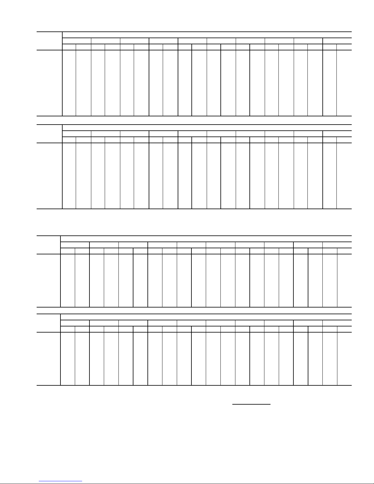
Table 29 — Fan Performance — 48AW,AY,A4,A5060 Units
AIRFLOW
(Cfm)
12,000 516 4.81 569 5.54 617 6.30 660 7.10 701 7.93 739 8.79 774 9.68 808 10.59 841 11.52 872 12.46
14,000 584 6.90 632 7.69 676 8.50 716 9.33 754 10.20 790 11.10 824 12.02 857 12.97 888 13.94 917 14.92
15,000 619 8.13 664 8.96 706 9.79 745 10.65 782 11.53 817 12.44 850 13.38 882 14.35 912 15.33 941 16.34
16,000 654 9.49 697 10.36 737 11.22 775 12.10 811 13.00 845 13.93 877 14.88 908 15.86 938 16.86 966 17.88
17,000 689 10.99 730 11.90 769 12.79 806 13.69 840 14.61 873 15.56 904 16.53 935 17.52 964 18.54 992 19.58
18,000 725 12.64 764 13.58 801 14.51 837 15.43 870 16.38 902 17.34 933 18.32 962 19.33 990 20.36 1018 21.41
19,000 760 14.43 798 15.41 834 16.37 868 17.32 900 18.29 932 19.27 961 20.27 990 21.29 1018 22.34 1045 23.40
20,000 796 16.37 833 17.39 867 18.39 900 19.37 931 20.36 962 21.36 991 22.38 1019 23.42 1046 24.48 1072 25.56
21,000 832 18.47 867 19.54 901 20.56 932 21.57 963 22.59 992 23.61 1020 24.65 1048 25.71 1074 26.78 1100 27.87
22,000 869 20.74 902 21.84 934 22.90 965 23.94 995 24.98 1023 26.03 1051 27.09 1077 28.17 1103 29.26 1129 30.36
23,000 905 23.17 937 24.31 968 25.40 998 26.48 1027 27.55 1055 28.62 1081 29.70 1107 30.79 1133 31.90 1157 33.02
24,000 942 25.78 973 26.95 1003 28.08 1032 29.18 1059 30.28 1086 31.38 1113 32.48 1138 33.59 1163 34.72 1187 35.86
25,000 978 28.56 1008 29.77 1037 30.93 1065 32.07 1092 33.20 1119 34.32 1144 35.44 1169 36.58 1193 37.72 — —
26,000 1015 31.52 1044 32.76 1072 33.96 1099 35.13 1125 36.29 1151 37.44 1176 38.59 — — — — — —
27,000 1052 34.66 1080 35.94 1107 37.18 1133 38.38 1159 39.57 1184 40.75 ————————
0.2 0.4 0.6 0.8 1.0 1.2 1.4 1.6 1.8 2.0
Rpm Bhp Rpm Bhp Rpm Bhp Rpm Bhp Rpm Bhp Rpm Bhp Rpm Bhp Rpm Bhp Rpm Bhp Rpm Bhp
AVAILABLE EXTERNAL STATIC PRESSURE (in. wg)
AIRFLOW
(Cfm)
12,000 901 13.42 930 14.38 958 15.36 985 16.34 1011 17.33 1036 18.33 1061 19.33 1085 20.34 1108 21.35 1131 22.36
14,000 946 15.92 974 16.94 1001 17.97 1027 19.01 1052 20.06 1077 21.12 1101 22.18 1125 23.25 1148 24.33 1170 25.42
15,000 970 17.36 997 18.40 1024 19.45 1049 20.51 1074 21.58 1099 22.67 1122 23.76 1146 24.86 1168 25.97 1191 27.08
16,000 994 18.93 1021 19.98 1047 21.05 1072 22.14 1097 23.23 1121 24.34 1144 25.45 1167 26.58 1190 27.71 — —
17,000 1019 20.63 1045 21.70 1071 22.79 1096 23.89 1120 25.01 1144 26.13 1167 27.27 1190 28.42 — — — —
18,000 1045 22.48 1070 23.57 1096 24.67 1120 25.79 1144 26.93 1167 28.07 1190 29.23 — — — — — —
19,000 1071 24.49 1096 25.59 1121 26.71 1145 27.84 1169 28.99 1192 30.16 ————————
20,000 1098 26.66 1123 27.77 1147 28.90 1171 30.05 1194 31.21 — — ————————
21,000 112528.99115030.12117331.26119732.42————————————
22,000 115331.49117732.63————————————————
23,000 118134.16——————————————————
24,000 ————————————————————
25,000 ————————————————————
26,000 ————————————————————
27,000 ————————————————————
2.2 2.4 2.6 2.8 3.0 3.2 3.4 3.6 3.8 4.0
Rpm Bhp Rpm Bhp Rpm Bhp Rpm Bhp Rpm Bhp Rpm Bhp Rpm Bhp Rpm Bhp Rpm Bhp Rpm Bhp
AVAILABLE EXTERNAL STATIC PRESSURE (in. wg)
Table 30 — Fan Performance — 50AW,AY020,025 and 50A4,A5020 Units
AIRFLOW
(CFM)
4,000 322 0.62 399 0.82 464 1.04 521 1.26 572 1.48 619 1.71 662 1.93 702 2.16 739 2.38 774 2.61
5,000 361 0.95 431 1.17 491 1.41 545 1.65 594 1.89 640 2.14 682 2.39 722 2.64 759 2.89 795 3.14
6,000 405 1.41 467 1.64 524 1.88 574 2.14 621 2.40 664 2.67 705 2.93 744 3.20 780 3.47 816 3.75
7,000 451 2.00 508 2.22 559 2.48 607 2.75 651 3.02 693 3.30 732 3.58 769 3.87 804 4.16 839 4.45
7,500 475 2.34 529 2.57 579 2.82 625 3.10 668 3.38 708 3.66 746 3.96 783 4.25 818 4.55 851 4.84
8,000 500 2.72 551 2.95 598 3.21 643 3.48 685 3.77 724 4.06 762 4.36 797 4.66 832 4.96 864 5.27
9,000 550 3.60 596 3.83 640 4.09 682 4.36 721 4.66 759 4.96 795 5.27 829 5.58 862 5.90 893 6.22
10,000 601 4.63 644 4.86 684 5.12 723 5.40 760 5.70 796 6.01 830 6.33 863 6.65 894 6.98 925 7.31
11,000 653 5.83 692 6.07 730 6.33 766 6.61 801 6.91 835 7.22 867 7.54 899 7.87 929 8.21 958 8.55
12,000 706 7.20 742 7.45 777 7.71 811 7.99 844 8.29 875 8.61 906 8.93 936 9.27 966 9.61 994 9.96
12,500 732 7.96 768 8.20 801 8.47 834 8.75 866 9.05 897 9.37 927 9.69 956 10.03 985 10.38 1012 10.73
13,000 759 8.76 793 9.01 826 9.27 857 9.56 888 9.86 918 10.17 947 10.50 976 10.84 1004 11.19 1031 11.54
0.2 0.4 0.6 0.8 1.0 1.2 1.4 1.6 1.8 2.0
Rpm Bhp Rpm Bhp Rpm Bhp Rpm Bhp Rpm Bhp Rpm Bhp Rpm Bhp Rpm Bhp Rpm Bhp Rpm Bhp
AVAILABLE EXTERNAL STATIC PRESSURE (in. wg)
AIRFLOW
(CFM)
4,000 808 2.84 840 3.06 870 3.29 900 3.52 928 3.75 955 3.98 981 4.21 1007 4.44 1031 4.67 1055 4.91
5,000 829 3.39 861 3.64 892 3.89 922 4.14 950 4.40 978 4.65 1005 4.90 1031 5.16 1056 5.41 1080 5.67
6,000 849 4.02 881 4.29 912 4.57 942 4.84 971 5.12 999 5.39 1026 5.67 1052 5.94 1077 6.22 1102 6.49
7,000 871 4.74 903 5.03 933 5.33 963 5.62 991 5.92 1019 6.21 1046 6.51 1072 6.80 1098 7.10 1123 7.40
7,500 883 5.14 915 5.44 945 5.75 974 6.05 1002 6.35 1030 6.66 1057 6.96 1083 7.27 1108 7.58 1133 7.88
8,000 896 5.58 927 5.89 957 6.20 985 6.51 1014 6.82 1041 7.13 1067 7.45 1093 7.76 1118 8.08 1143 8.39
9,000 924 6.54 954 6.86 983 7.19 1011 7.51 1038 7.84 1064 8.17 1090 8.50 1116 8.83 1141 9.16 1165 9.49
10,000 954 7.64 983 7.98 1011 8.31 1038 8.65 1065 8.99 1091 9.34 1116 9.68 1141 10.02 1165 10.37 1189 10.72
11,000 987 8.89 1015 9.24 1042 9.59 1068 9.94 1094 10.29 1119 10.65 1144 11.01 1168 11.36 1191 11.72 — —
12,000 1022 10.31 1048 10.67 1075 11.03 1100 11.39 1125 11.75 1150 12.12 1173 12.48 1197 12.85 — — — —
12,500 1039 11.08 1066 11.44 1092 11.81 1117 12.17 1141 12.54 1165 12.91 1189 13.28 — — — — — —
13,000 1058 11.90 1084 12.26 1109 12.63 1134 13.00 1158 13.37 1182 13.75 — — — — — — — —
LEGEND
Bhp — Brake Horsepower
edb — Entering Dry Bulb
ewb — Entering Wet Bulb
NOTES:
1. Fan performance is based on wet coils, economizer, roof curb, cabinet
losses, and clean 2-in. filters.
2.2 2.4 2.6 2.8 3.0 3.2 3.4 3.6 3.8 4.0
Rpm Bhp Rpm Bhp Rpm Bhp Rpm Bhp Rpm Bhp Rpm Bhp Rpm Bhp Rpm Bhp Rpm Bhp Rpm Bhp
AVAILABLE EXTERNAL STATIC PRESSURE (in. wg)
2. Conversion — Bhp to watts:
Watts =
3. Variable air volume units will operate down to 70 cfm/ton. Performance at
70 cfm/ton is limited to unloaded operation and may be additionally limited
by edb and ewb conditions.
Bhp x 746
Motor efficiency
21
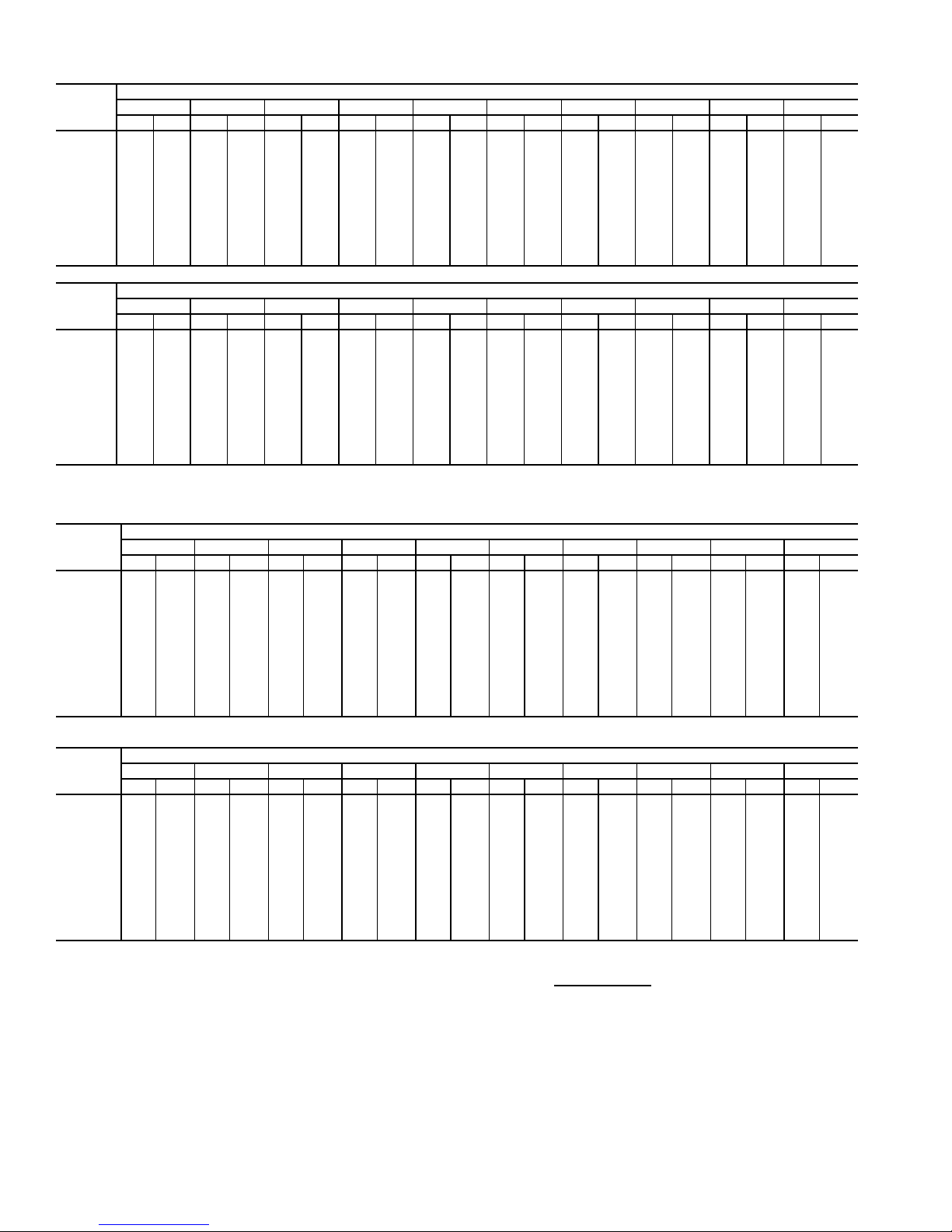
Table 31 — Fan Performance — 50AW,AY027,030 and 50A4,A5025-030 Units
AIRFLOW
(CFM)
4,000 325 0.62 402 0.83 466 1.05 523 1.27 574 1.49 620 1.72 663 1.94 703 2.17 740 2.39 776 2.62
5,000 366 0.97 435 1.19 495 1.42 548 1.67 597 1.91 642 2.16 685 2.41 724 2.65 762 2.90 797 3.16
6,000 411 1.43 473 1.66 529 1.91 579 2.16 625 2.43 668 2.69 709 2.96 747 3.23 784 3.50 819 3.77
7,000 459 2.02 515 2.25 566 2.51 613 2.78 657 3.06 698 3.34 737 3.62 774 3.91 809 4.20 843 4.49
8,000 508 2.76 559 2.99 606 3.25 650 3.53 691 3.82 731 4.11 768 4.41 803 4.71 837 5.01 870 5.32
9,000 560 3.64 605 3.88 649 4.14 690 4.42 729 4.72 766 5.02 802 5.33 835 5.64 868 5.96 900 6.28
10,000 612 4.68 654 4.92 694 5.19 732 5.47 769 5.77 804 6.09 838 6.40 870 6.73 902 7.06 932 7.39
11,000 665 5.89 703 6.14 740 6.41 776 6.69 811 7.00 844 7.31 876 7.64 907 7.97 937 8.31 967 8.65
12,000 718 7.28 754 7.53 788 7.80 822 8.09 854 8.39 886 8.71 916 9.04 946 9.38 975 9.72 1003 10.07
13,000 772 8.85 806 9.11 838 9.38 869 9.67 899 9.98 929 10.30 958 10.63 987 10.97 1014 11.32 1041 11.68
14,000 826 10.61 858 10.87 888 11.15 917 11.44 946 11.75 974 12.07 1002 12.41 1029 12.75 1055 13.10 1081 13.46
15,000 881 12.57 910 12.84 939 13.12 967 13.41 994 13.72 1021 14.05 1047 14.38 1073 14.73 1098 15.08 1123 15.45
AIRFLOW
(CFM)
4,000 809 2.84 841 3.07 872 3.30 901 3.53 929 3.76 956 3.99 982 4.22 1008 4.45 1032 4.68 1056 4.92
5,000 831 3.41 863 3.66 894 3.91 924 4.16 952 4.41 980 4.67 1007 4.92 1032 5.17 1057 5.43 1082 5.68
6,000 852 4.05 884 4.32 915 4.59 945 4.87 974 5.14 1001 5.42 1028 5.69 1054 5.97 1080 6.24 1105 6.52
7,000 875 4.78 907 5.07 937 5.37 967 5.66 995 5.95 1023 6.25 1049 6.55 1076 6.84 1101 7.14 1126 7.44
8,000 901 5.63 932 5.94 961 6.25 990 6.56 1018 6.87 1045 7.18 1072 7.50 1097 7.81 1123 8.13 1147 8.44
9,000 930 6.60 960 6.93 988 7.25 1016 7.58 1043 7.91 1070 8.23 1096 8.57 1121 8.90 1146 9.23 1170 9.56
10,000 961 7.72 990 8.06 1018 8.40 1045 8.74 1071 9.08 1097 9.42 1122 9.76 1147 10.11 1171 10.46 1194 10.80
11,000 995 8.99 1022 9.34 1049 9.69 1075 10.04 1101 10.39 1126 10.75 1151 11.11 1175 11.47 1198 11.82 — —
12,000 1030 10.43 1057 10.78 1083 11.14 1108 11.51 1133 11.87 1157 12.24 1181 12.61 — — — — — —
13,000 1068 12.04 1093 12.40 1119 12.77 1143 13.14 1167 13.52 1191 13.89 — — — — — — — —
14,000 1107 13.83 1131 14.20 1156 14.58 1179 14.96 ————————————
15,000 1147 15.82 1171 16.19 1194 16.58 — — ————————————
0.2 0.4 0.6 0.8 1.0 1.2 1.4 1.6 1.8 2.0
Rpm Bhp Rpm Bhp Rpm Bhp Rpm Bhp Rpm Bhp Rpm Bhp Rpm Bhp Rpm Bhp Rpm Bhp Rpm Bhp
2.2 2.4 2.6 2.8 3.0 3.2 3.4 3.6 3.8 4.0
Rpm Bhp Rpm Bhp Rpm Bhp Rpm Bhp Rpm Bhp Rpm Bhp Rpm Bhp Rpm Bhp Rpm Bhp Rpm Bhp
AVAILABLE EXTERNAL STATIC PRESSURE (in. wg)
AVAILABLE EXTERNAL STATIC PRESSURE (in. wg)
Table 32 — Fan Performance — 50AW,AY,A4,A5035 Units
AIRFLOW
(Cfm)
7,000 522 2.06 573 2.32 620 2.57 664 2.82 705 3.06 744 3.30 780 3.54 815 3.78 849 4.01 881 4.24
8,000 576 2.75 622 3.03 665 3.30 706 3.57 745 3.84 782 4.10 817 4.36 850 4.62 883 4.87 914 5.12
9,000 630 3.57 672 3.86 712 4.16 750 4.45 787 4.74 822 5.02 855 5.30 888 5.58 919 5.86 949 6.13
10,000 686 4.52 724 4.84 761 5.15 797 5.46 831 5.77 864 6.07 896 6.37 927 6.67 957 6.97 986 7.26
10,500 714 5.05 750 5.38 786 5.70 821 6.02 854 6.34 886 6.65 917 6.96 947 7.27 977 7.57 1005 7.87
11,000 742 5.62 777 5.95 811 6.28 845 6.61 877 6.94 909 7.26 939 7.58 968 7.90 997 8.21 1025 8.52
12,000 799 6.88 831 7.22 863 7.57 894 7.91 925 8.25 954 8.60 983 8.93 1011 9.27 1039 9.60 1065 9.93
13,000 856 8.29 886 8.65 916 9.01 945 9.37 974 9.72 1002 10.08 1029 10.44 1056 10.79 1082 11.14 1108 11.49
14,000 914 9.87 942 10.24 969 10.61 997 10.98 1024 11.36 1050 11.73 1076 12.10 1102 12.47 1127 12.84 1152 13.20
15,000 971 11.62 998 12.00 1024 12.39 1050 12.77 1075 13.16 1100 13.54 1125 13.93 1149 14.31 1173 14.70 1197 15.08
16,000 1029 13.55 1054 13.94 1079 14.34 1103 14.74 1127 15.13 1151 15.53 1174 15.93 1198 16.33 1220 16.73 1243 17.12
17,000 1088 15.66 1111 16.07 1134 16.47 1157 16.88 1180 17.29 1203 17.70 1225 18.11 1247 18.53 1269 18.93 1290 19.34
17,500 1117 16.79 1140 17.20 1162 17.61 1184 18.02 1207 18.44 1229 18.86 1250 19.27 1272 19.69 1293 20.11 — —
0.2 0.4 0.6 0.8 1.0 1.2 1.4 1.6 1.8 2.0
Rpm Bhp Rpm Bhp Rpm Bhp Rpm Bhp Rpm Bhp Rpm Bhp Rpm Bhp Rpm Bhp Rpm Bhp Rpm Bhp
AVAILABLE EXTERNAL STATIC PRESSURE (in. wg)
AIRFLOW
(Cfm)
7,000 912 4.46 942 4.68 970 4.90 998 5.12 1025 5.33 1051 5.54 1076 5.75 1101 5.96 1124 6.16 1148 6.36
8,000 944 5.37 973 5.62 1001 5.86 1029 6.11 1055 6.35 1081 6.58 1106 6.82 1130 7.05 1154 7.28 1177 7.51
9,000 978 6.40 1006 6.67 1034 6.93 1060 7.20 1086 7.46 1112 7.72 1136 7.98 1160 8.23 1184 8.49 1207 8.74
10,000 1014 7.55 1041 7.84 1068 8.12 1094 8.41 1119 8.69 1144 8.97 1168 9.25 1192 9.52 1215 9.80 1238 10.07
10,500 1033 8.17 1059 8.47 1086 8.77 1111 9.06 1136 9.35 1161 9.64 1184 9.93 1208 10.22 1231 10.50 1253 10.79
11,000 1052 8.83 1078 9.14 1104 9.44 1129 9.75 1154 10.05 1178 10.35 1201 10.64 1224 10.94 1247 11.23 1269 11.53
12,000 1091 10.26 1117 10.58 1142 10.90 1166 11.23 1190 11.54 1213 11.86 1236 12.18 1259 12.49 1281 12.80 — —
13,000 1133 11.83 1157 12.17 1181 12.51 1205 12.85 1228 13.19 1251 13.52 1273 13.86 1295 14.19 — — — —
14,000 1176 13.56 1199 13.92 1222 14.28 1245 14.63 1268 14.99 1290 15.34 — ———————
15,000 122015.45124315.83126516.20128716.58————————————
16,000 126517.52128717.91————————————————
17,000 ————————————————————
17,500 ————————————————————
LEGEND
Bhp — Brake Horsepower
edb — Entering Dry Bulb
ewb — Entering Wet Bulb
NOTES:
1. Fan performance is based on wet coils, economizer, roof curb, cabinet
losses, and clean 2-in. filters.
2.2 2.4 2.6 2.8 3.0 3.2 3.4 3.6 3.8 4.0
Rpm Bhp Rpm Bhp Rpm Bhp Rpm Bhp Rpm Bhp Rpm Bhp Rpm Bhp Rpm Bhp Rpm Bhp Rpm Bhp
AVAILABLE EXTERNAL STATIC PRESSURE (in. wg)
2. Conversion — Bhp to watts:
Watts =
3. Variable air volume units will operate down to 70 cfm/ton. Performance at
70 cfm/ton is limited to unloaded operation and may be additionally limited
by edb and ewb conditions.
Bhp x 746
Motor efficiency
22
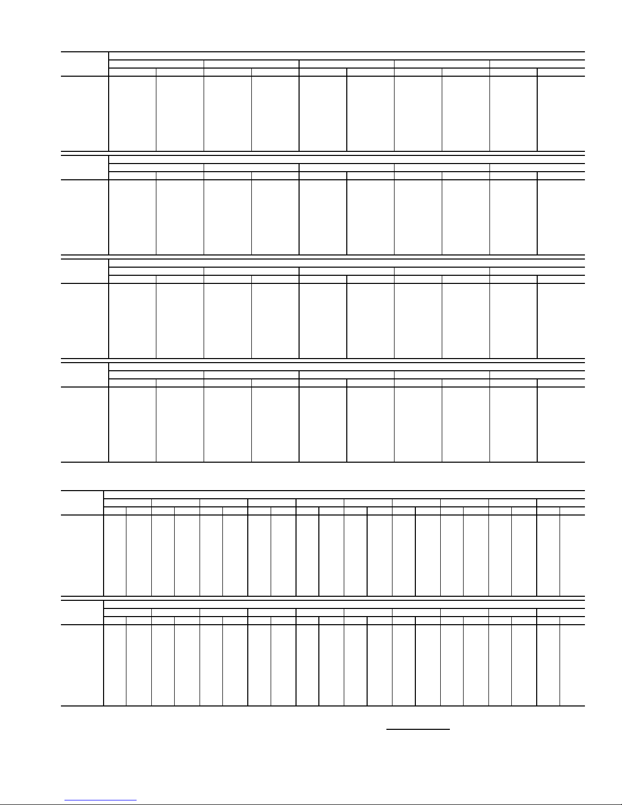
Table 33 — Fan Performance — 50AW,AY036 Units
AIRFLOW
(Cfm)
7,000 451 2.13 503 2.49 552 2.86 597 3.23 641 3.60
8,000 499 2.88 546 3.27 590 3.66 632 4.06 672 4.46
9,000 548 3.78 591 4.20 631 4.62 670 5.04 708 5.47
10,000 599 4.86 637 5.30 675 5.74 711 6.19 746 6.64
11,000 649 6.11 685 6.57 720 7.04 753 7.51 786 7.99
12,000 701 7.54 734 8.03 766 8.52 797 9.02 828 9.52
13,000 753 9.18 783 9.69 813 10.21 842 10.72 871 11.25
14,000 805 11.03 833 11.56 861 12.09 889 12.63 916 13.18
15,000 857 13.09 884 13.64 910 14.20 936 14.76 962 15.32
16,000 910 15.38 935 15.95 960 16.53 984 17.11 1008 17.69
17,000 963 17.91 986 18.50 1010 19.09 1033 19.69 1056 20.30
17,500 989 19.26 1012 19.86 1035 20.47 1058 21.08 1080 21.69
AIRFLOW
(Cfm)
7,000 682 3.99 722 4.39 760 4.80 797 5.22 832 5.65
8,000 711 4.87 748 5.28 784 5.70 819 6.14 853 6.58
9,000 744 5.90 778 6.33 812 6.77 845 7.22 877 7.67
10,000 779 7.09 812 7.55 844 8.01 875 8.47 905 8.94
11,000 817 8.47 848 8.94 878 9.43 907 9.91 936 10.40
12,000 857 10.02 886 10.52 915 11.03 943 11.53 970 12.04
13,000 899 11.77 927 12.30 953 12.82 980 13.35 1006 13.88
14,000 942 13.73 968 14.27 994 14.82 1019 15.37 1044 15.92
15,000 987 15.89 1011 16.46 1036 17.03 1060 17.61 1083 18.18
16,000 1032 18.28 1056 18.87 1079 19.47 1101 20.06 1124 20.66
17,000 1078 20.91 1101 21.52 1123 22.13 1145 22.75 1166 23.36
17,500 1102 22.31 1124 22.93 1145 23.55 1166 24.18 1187 24.80
AIRFLOW
(Cfm)
7,000 866 6.09 899 6.54 931 6.99 961 7.45 991 7.91
8,000 885 7.03 917 7.48 948 7.95 978 8.42 1007 8.90
9,000 908 8.13 939 8.60 968 9.08 997 9.56 1026 10.05
10,000 934 9.42 963 9.90 992 10.39 1020 10.89 1047 11.39
11,000 964 10.89 992 11.39 1019 11.89 1045 12.40 1071 12.91
12,000 996 12.55 1023 13.07 1048 13.59 1074 14.11 1099 14.64
13,000 1031 14.41 1056 14.95 1081 15.48 1105 16.03 1129 16.57
14,000 1068 16.48 1092 17.03 1115 17.59 1138 18.15 1161 18.71
15,000 1106 18.75 1129 19.33 1151 19.91 1174 20.48 1196 21.07
16,000 1146 21.25 1168 21.85 1189 22.45 1211 23.04 1232 23.64
17,000 1187 23.98 1208 24.60 1229 25.21 1249 25.83 1270 26.46
17,500 1208 25.43 1229 26.06 1249 26.69 1269 27.32 1289 27.95
AIRFLOW
(Cfm)
7,000 1020 8.39 1047 8.86 1074 9.34 1101 9.83 1126 10.32
8,000 1036 9.39 1063 9.88 1090 10.38 1116 10.88 1142 11.39
9,000 1053 10.55 1080 11.05 1107 11.56 1133 12.08 1158 12.60
10,000 1073 11.89 1100 12.41 1125 12.93 1151 13.45 1175 13.99
11,000 1097 13.43 1122 13.96 1147 14.49 1171 15.02 1195 15.56
12,000 1123 15.17 1147 15.71 1171 16.25 1195 16.80 1218 17.35
13,000 1152 17.12 1175 17.67 1198 18.22 1221 18.78 1243 19.35
14,000 1184 19.27 1206 19.84 1228 20.41 1250 20.99 1271 21.56
15,000 1217 21.65 1239 22.23 1260 22.82 1280 23.41 — —
16,000 1253 24.25 1273 24.85 1293 25.45 — — — —
17,000 128927.07————————
17,500 ——————————
0.2 0.4 0.6 0.8 1.0
Rpm Bhp Rpm Bhp Rpm Bhp Rpm Bhp Rpm Bhp
1.2 1.4 1.6 1.8 2.0
Rpm Bhp Rpm Bhp Rpm Bhp Rpm Bhp Rpm Bhp
2.2 2.4 2.6 2.8 3.0
Rpm Bhp Rpm Bhp Rpm Bhp Rpm Bhp Rpm Bhp
3.2 3.4 3.6 3.8 4.0
Rpm Bhp Rpm Bhp Rpm Bhp Rpm Bhp Rpm Bhp
AVAILABLE EXTERNAL STATIC PRESSURE (in. wg)
AVAILABLE EXTERNAL STATIC PRESSURE (in. wg)
AVAILABLE EXTERNAL STATIC PRESSURE (in. wg)
AVAILABLE EXTERNAL STATIC PRESSURE (in. wg)
Table 34 — Fan Performance — 50AW,AY,A4,A5040 Units
AIRFLOW
(Cfm)
8,000 499 2.88 546 3.27 590 3.66 632 4.06 672 4.46 711 4.87 748 5.28 784 5.70 819 6.14 853 6.58
9,000 548 3.78 591 4.20 631 4.62 670 5.04 708 5.47 744 5.90 778 6.33 812 6.77 845 7.22 877 7.67
10,000 599 4.86 637 5.30 675 5.74 711 6.19 746 6.64 779 7.09 812 7.55 844 8.01 875 8.47 905 8.94
11,000 649 6.11 685 6.57 720 7.04 753 7.51 786 7.99 817 8.47 848 8.94 878 9.43 907 9.91 936 10.40
12,000 701 7.54 734 8.03 766 8.52 797 9.02 828 9.52 857 10.02 886 10.52 915 11.03 943 11.53 970 12.04
13,000 753 9.18 783 9.69 813 10.21 842 10.72 871 11.25 899 11.77 927 12.30 953 12.82 980 13.35 1006 13.88
14,000 805 11.03 833 11.56 861 12.09 889 12.63 916 13.18 942 13.73 968 14.27 994 14.82 1019 15.37 1044 15.92
15,000 857 13.09 884 13.64 910 14.20 936 14.76 962 15.32 987 15.89 1011 16.46 1036 17.03 1060 17.61 1083 18.18
16,000 910 1 5.38 935 15.95 960 16.53 984 17.11 1008 17.69 1032 18.28 1056 18.87 1079 19.47 1101 20.06 1124 20.66
17,000 963 17.91 986 18.50 1010 19.09 1033 19.69 1056 20.30 1078 20.91 1101 21.52 1123 22.13 1145 22.75 1166 23.36
18,000 1016 20.68 1038 21.29 1060 21.90 1082 22.52 1104 23.15 1126 23.77 1147 24.41 1168 25.04 1189 25.67 1209 26.31
19,000 1069 23.71 1090 24.33 1111 24.96 1132 25.60 1153 26.25 1173 26.89 1194 27.54 1214 28.19 1234 28.85 — —
20,000 112226.99114227.64116228.29118228.95————————————
AIRFLOW
(Cfm)
8,000 885 7.03 917 7.48 948 7.95 978 8.42 1007 8.90 1036 9.39 1063 9.88 1090 10.38 1116 10.88 1142 11.39
9,000 908 8.13 939 8.60 968 9.08 997 9.56 1026 10.05 1053 10.55 1080 11.05 1107 11.56 1133 12.08 1158 12.60
10,000 934 9.42 963 9.90 992 10.39 1020 10.89 1047 11.39 1073 11.89 1100 12.41 1125 12.93 11 51 13.45 1175 13.99
11,000 964 10.89 992 11.39 1019 11.89 1045 12.40 1071 12.91 1097 13.43 1122 13.96 1147 14.49 1171 15.02 1195 15.56
12,000 996 1 2.55 1023 13.07 1048 13.59 1074 14.11 1099 14.64 1123 15.17 1147 15.71 1171 16.25 1195 16.80 1218 17.35
13,000 1031 14.41 1056 14.95 1081 15.48 1105 16.03 1129 16.57 1152 17.12 1175 17.67 1198 18.22 1221 18.78 1243 19.35
14,000 1068 16.48 1092 17.03 1115 17.59 1138 18.15 1161 18.71 1184 19.27 1206 19.84 1228 20.41 1250 20.99 1271 21.56
15,000 1106 18.75 1129 19.33 1151 19.91 1174 20.48 1196 21.07 1217 21.65 1239 22.23 1260 22.82 1280 23.41 — —
16,000 114621.25116821.85118922.45121123.04123223.64125324.25127324.85129325.45————
17,000 118723.98120824.60122925.21124925.83127026.46128927.07————————
18,000 123026.95125027.58126928.22128928.86————————————
19,000 ————————————————————
20,000 ————————————————————
LEGEND
Bhp — Brake Horsepower
edb — Entering Dry Bulb
ewb — Entering Wet Bulb
NOTES:
1. Fan performance is based on wet coils, economizer, roof curb, cabinet losses, and clean
2-in. filters.
0.20.40.60.81.01.21.41.61.82.0
Rpm Bhp Rpm Bhp Rpm Bhp Rpm Bhp Rpm Bhp Rpm Bhp Rpm Bhp Rpm Bhp Rpm Bhp Rpm Bhp
2.22.42.62.83.03.23.43.63.84.0
Rpm Bhp Rpm Bhp Rpm Bhp Rpm Bhp Rpm Bhp Rpm Bhp Rpm Bhp Rpm Bhp Rpm Bhp Rpm Bhp
AVAILABLE EXTERNAL STATIC PRESSURE (in. wg)
AVAILABLE EXTERNAL STATIC PRESSURE (in. wg)
2. Conversion — Bhp to watts:
Watts =
3. Variable air volume units will operate down to 70 cfm/ton. Performance at 70 cfm/ton is
limited to unloaded operation and may be additional limited by edb and ewb conditions.
Bhp x 746
Motor efficiency
23
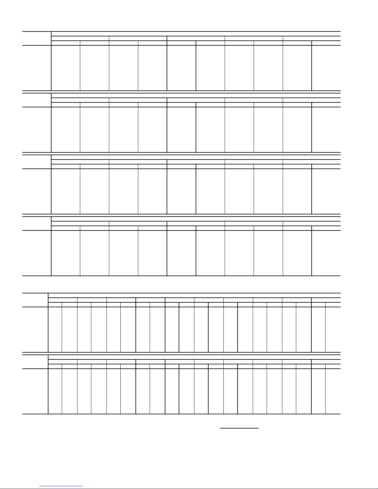
Table 35 — Fan Performance — 50AW,AY041 Units
AIRFLOW
(Cfm)
8,000 499 2.88 546 3.27 590 3.66 632 4.06 672 4.46
9,000 548 3.78 591 4.20 631 4.62 670 5.04 708 5.47
10,000 599 4.86 637 5.30 675 5.74 711 6.19 746 6.64
11,000 649 6.11 685 6.57 720 7.04 753 7.51 786 7.99
12,000 701 7.54 734 8.03 766 8.52 797 9.02 828 9.52
13,000 753 9.18 783 9.69 813 10.21 842 10.72 871 11.25
14,000 805 11.03 833 11.56 861 12.09 889 12.63 916 13.18
15,000 857 13.09 884 13.64 910 14.20 936 14.76 962 15.32
16,000 910 15.38 935 15.95 960 16.53 984 17.11 1008 17.69
17,000 963 17.91 986 18.50 1010 19.09 1033 19.69 1056 20.30
18,000 1016 20.68 1038 21.29 1060 21.90 1082 22.52 1104 23.15
19,000 1069 23.71 1090 24.33 1111 24.96 1132 25.60 1153 26.25
20,000 1122 26.99 1142 27.64 1162 28.29 1182 28.95 — —
AIRFLOW
(Cfm)
8,000 711 4.87 748 5.28 784 5.70 819 6.14 853 6.58
9,000 744 5.90 778 6.33 812 6.77 845 7.22 877 7.67
10,000 779 7.09 812 7.55 844 8.01 875 8.47 905 8.94
11,000 817 8.47 848 8.94 878 9.43 907 9.91 936 10.40
12,000 857 10.02 886 10.52 915 11.03 943 11.53 970 12.04
13,000 899 11.77 927 12.30 953 12.82 980 13.35 1006 13.88
14,000 942 13.73 968 14.27 994 14.82 1019 15.37 1044 15.92
15,000 987 15.89 1011 16.46 1036 17.03 1060 17.61 1083 18.18
16,000 1032 18.28 1056 18.87 1079 19.47 1101 20.06 1124 20.66
17,000 1078 20.91 1101 21.52 1123 22.13 1145 22.75 1166 23.36
18,000 1126 23.77 1147 24.41 1168 25.04 1189 25.67 1209 26.31
19,000 1173 26.89 1194 27.54 1214 28.19 1234 28.85 — —
20,000 ——————————
AIRFLOW
(Cfm)
8,000 885 7.03 917 7.48 948 7.95 978 8.42 1007 8.90
9,000 908 8.13 939 8.60 968 9.08 997 9.56 1026 10.05
10,000 934 9.42 963 9.90 992 10.39 1020 10.89 1047 11.39
11,000 964 10.89 992 11.39 1019 11.89 1045 12.40 1071 12.91
12,000 996 12.55 1023 13.07 1048 13.59 1074 14.11 1099 14.64
13,000 1031 14.41 1056 14.95 1081 15.48 1105 16.03 1129 16.57
14,000 1068 16.48 1092 17.03 1115 17.59 1138 18.15 1161 18.71
15,000 1106 18.75 1129 19.33 1151 19.91 1174 20.48 1196 21.07
16,000 1146 21.25 1168 21.85 1189 22.45 1211 23.04 1232 23.64
17,000 1187 23.98 1208 24.60 1229 25.21 1249 25.83 1270 26.46
18,000 1230 26.95 1250 27.58 1269 28.22 1289 28.86 — —
19,000 ——————————
20,000 ——————————
AIRFLOW
(Cfm)
8,000 1036 9.39 1063 9.88 1090 10.38 1116 10.88 1142 11.39
9,000 1053 10.55 1080 11.05 1107 11.56 1133 12.08 1158 12.60
10,000 1073 11.89 1100 12.41 1125 12.93 1151 13.45 1175 13.99
11,000 1097 13.43 1122 13.96 1147 14.49 1171 15.02 1195 15.56
12,000 1123 15.17 1147 15.71 1171 16.25 1195 16.80 1218 17.35
13,000 1152 17.12 1175 17.67 1198 18.22 1221 18.78 1243 19.35
14,000 1184 19.27 1206 19.84 1228 20.41 1250 20.99 1271 21.56
15,000 1217 21.65 1239 22.23 1260 22.82 1280 23.41 — —
16,000 1253 24.25 1273 24.85 1293 25.45 — — — —
17,000 128927.07————————
18,000 ——————————
19,000 ——————————
20,000 ——————————
0.2 0.4 0.6 0.8 1.0
Rpm Bhp Rpm Bhp Rpm Bhp Rpm Bhp Rpm Bhp
1.2 1.4 1.6 1.8 2.0
Rpm Bhp Rpm Bhp Rpm Bhp Rpm Bhp Rpm Bhp
2.2 2.4 2.6 2.8 3.0
Rpm Bhp Rpm Bhp Rpm Bhp Rpm Bhp Rpm Bhp
3.2 3.4 3.6 3.8 4.0
Rpm Bhp Rpm Bhp Rpm Bhp Rpm Bhp Rpm Bhp
AVAILABLE EXTERNAL STATIC PRESSURE (in. wg)
AVAILABLE EXTERNAL STATIC PRESSURE (in. wg)
AVAILABLE EXTERNAL STATIC PRESSURE (in. wg)
AVAILABLE EXTERNAL STATIC PRESSURE (in. wg)
Table 36 — Fan Performance — 50AW,AY,A4,A5050 Units
AIRFLOW
(Cfm)
8,000 509 2.95 555 3.35 599 3.74 640 4.14 680 4.54 718 4.95 755 5.36 791 5.79 826 6.22 859 6.66
9,000 558 3.87 600 4.29 640 4.71 678 5.13 715 5.56 751 5.99 786 6.42 819 6.87 852 7.31 884 7.77
10,000 608 4.96 646 5.40 683 5.85 719 6.30 754 6.75 787 7.20 819 7.66 851 8.12 882 8.58 912 9.06
11,000 659 6.23 694 6.69 728 7.16 762 7.64 794 8.11 825 8.59 856 9.07 886 9.55 915 10.04 943 10.53
12,000 710 7.68 743 8.17 775 8.67 806 9.17 836 9.67 866 10.17 895 10.67 923 11.17 950 11.68 978 12.19
13,000 763 9.35 793 9.86 823 10.37 852 10.89 880 11.42 908 11.94 935 12.47 962 12.99 988 13.52 1014 14.05
14,000 815 11.22 843 11.75 871 12.29 899 12.83 925 13.38 952 13.92 978 14.47 1003 15.02 1028 15.57 1052 16.12
15,000 868 13.31 895 13.86 921 14.42 946 14.98 972 15.55 997 16.12 1021 16.69 1045 17.26 1069 17.83 1092 18.41
16,000 921 15.64 946 16.21 971 16.78 995 17.37 1019 17.96 1043 18.54 1066 19.14 1089 19.73 1111 20.32 1134 20.92
17,000 974 18.20 998 18.79 1021 19.39 1044 19.99 1067 20.60 1089 21.21 1112 21.82 1134 22.43 1155 23.05 1176 23.66
18,000 1028 21.01 1050 21.62 1072 22.24 1094 22.86 1116 23.49 1137 24.12 1158 24.75 1179 25.38 1200 26.02 1220 26.65
19,000 1081 24.08 1103 24.71 1124 25.35 1145 25.99 1165 26.63 1185 27.28 1206 27.93 1226 28.58 1245 29.24 1265 29.90
20,000 1135 27.42 1155 28.06 1175 28.72 1195 29.38 1215 30.04 1234 30.71 1254 31.38 1273 32.05 1292 32.72 — —
AIRFLOW
(Cfm)
8,000 892 7.12 923 7.57 954 8.04 984 8.52 1013 9.00 1041 9.49 1069 9.98 1095 10.48 1121 10.98 1147 11.49
9,000 915 8.23 945 8.70 975 9.18 1003 9.67 1032 10.16 1059 10.66 1086 11.16 1112 11.67 1138 12.19 1163 12.71
10,000 941 9.53 970 10.02 998 10.51 1026 11.00 1053 11.51 1080 12.01 1106 12.53 1131 13.05 1156 13.58 1181 14.11
11,000 971 11.02 999 11.52 1026 12.02 1052 12.53 1078 13.05 1103 13.57 1128 14.09 1153 14.63 1177 15.16 1201 15.71
12,000 1004 12.70 1030 13.22 1056 13.74 1081 14.26 1106 14.79 1130 15.33 1154 15.86 1178 16.41 1201 16.96 1224 17.51
13,000 1039 14.59 1064 15.12 1088 15.66 1113 16.20 1136 16.74 1160 17.29 1183 17.85 1206 18.40 1228 18.96 1250 19.53
14,000 1076 16.68 1100 17.23 1123 17.79 1147 18.35 1169 18.91 1192 19.48 1214 20.04 1236 20.62 1257 21.19 1279 21.77
15,000 1115 18.98 1138 19.56 1160 20.14 1182 20.72 1204 21.30 1226 21.88 1247 22.47 1268 23.05 1289 23.65 — —
16,000 1156 21.52 1178 22.11 1199 22.71 1220 23.31 1241 23.91 1262 24.51 1282 25.12 — —————
17,000 1198 24.28 1218 24.90 1239 25.52 1259 26.14 1279 26.76 1299 27.38 — — — —————
18,000 1240 27.29 1260 27.93 1280 28.57 1300 29.21 — — ——————————
19,000 1284 30.55 — — — ———————————————
20,000 ————————————————————
LEGEND
Bhp — Brake Horsepower
edb — Entering Dry Bulb
ewb — Entering Wet Bulb
NOTES:
1. Fan performance is based on wet coils, economizer, roof curb, cabinet losses, and clean 2-in.
filters.
0.2 0.4 0.6 0.8 1.0 1.2 1.4 1.6 1.8 2.0
Rpm Bhp Rpm Bhp Rpm Bhp Rpm Bhp Rpm Bhp Rpm Bhp Rpm Bhp Rpm Bhp Rpm Bhp Rpm Bhp
2.2 2.4 2.6 2.8 3.0 3.2 3.4 3.6 3.8 4.0
Rpm Bhp Rpm Bhp Rpm Bhp Rpm Bhp Rpm Bhp Rpm Bhp Rpm Bhp Rpm Bhp Rpm Bhp Rpm Bhp
AVAILABLE E XTERNAL STATIC PRESSURE (in. wg)
AVAILABLE E XTERNAL STATIC PRESSURE (in. wg)
2. Conversion — Bhp to watts:
Watts =
3. Variable air volume units will operate down to 70 cfm/ton. Performance at 70 cfm/ton is limited to
unloaded operation and may be additionally limited by edb and ewb conditions.
Motor efficiency
Bhp x 746
24
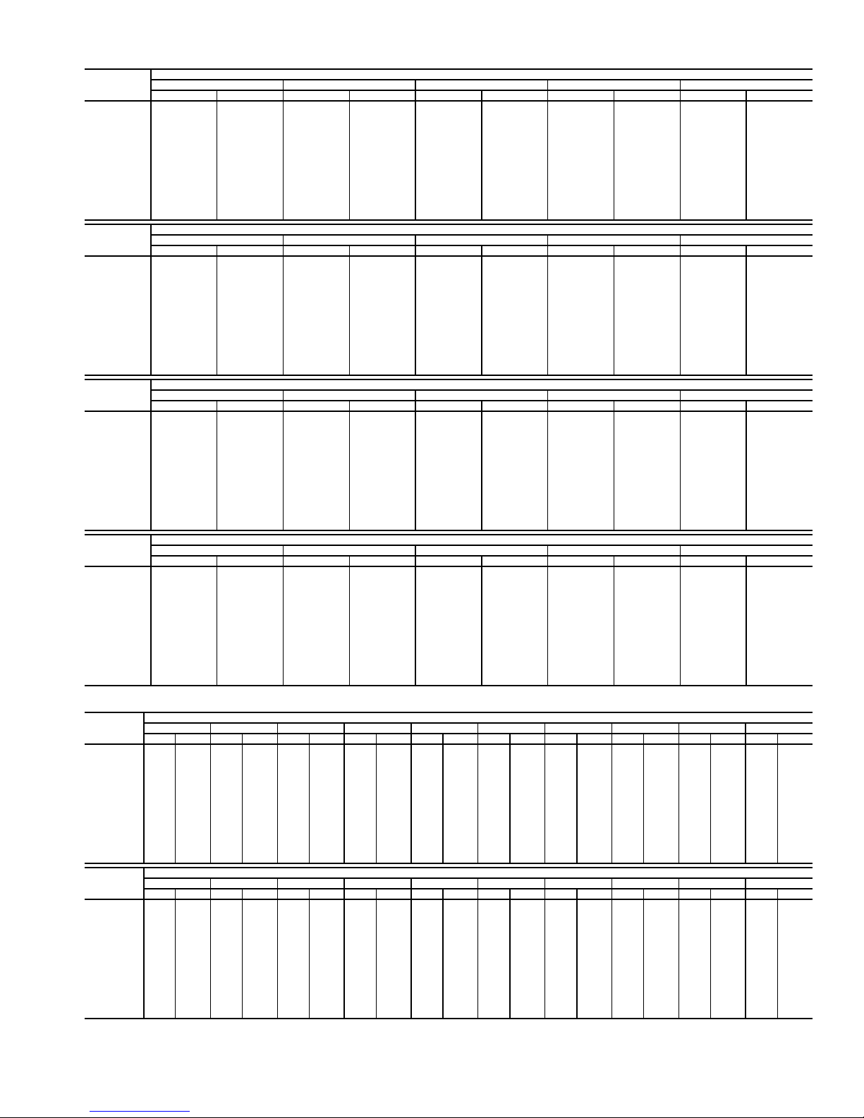
Table 37 — Fan Performance — 50AW,AY051 Units
AIRFLOW
(Cfm)
10,000 429 2.98 488 3.61 539 4.26 585 4.95 627 5.66
12,000 490 4.48 543 5.17 591 5.88 634 6.61 673 7.36
13,000 522 5.39 572 6.11 618 6.85 659 7.61 698 8.38
14,000 554 6.41 602 7.17 645 7.94 686 8.72 723 9.51
15,000 586 7.56 632 8.34 674 9.14 713 9.94 749 10.77
16,000 619 8.83 663 9.64 703 10.46 741 11.30 776 12.14
17,000 652 10.23 694 11.07 733 11.92 769 12.78 803 13.65
18,000 685 11.76 725 12.63 763 13.51 798 14.39 831 15.29
19,000 719 13.44 757 14.33 793 15.23 827 16.14 860 17.07
20,000 753 15.26 789 16.18 824 17.10 857 18.04 888 18.99
21,000 787 17.23 822 18.17 855 19.12 887 20.08 918 21.05
22,000 821 19.35 855 20.32 887 21.29 918 22.28 947 23.28
23,000 855 21.63 888 22.62 919 23.62 949 24.63 977 25.65
24,000 889 24.07 921 25.08 951 26.11 980 27.14 1008 28.19
25,000 924 26.67 954 27.71 983 28.76 1011 29.82 1038 30.89
AIRFLOW
(Cfm)
10,000 666 6.41 703 7.17 737 7.96 770 8.78 801 9.61
12,000 711 8.14 746 8.94 779 9.76 811 10.60 841 11.45
13,000 734 9.18 769 9.99 801 10.82 832 11.68 862 12.55
14,000 759 10.33 792 11.16 824 12.01 855 12.88 884 13.76
15,000 784 11.60 816 12.45 848 13.32 878 14.21 906 15.11
16,000 810 13.00 841 13.87 872 14.76 901 15.66 929 16.58
17,000 836 14.53 867 15.42 897 16.33 926 17.25 953 18.19
18,000 863 16.20 893 17.11 922 18.04 950 18.98 978 19.93
19,000 890 18.00 920 18.94 949 19.88 976 20.84 1003 21.81
20,000 918 19.94 947 20.90 975 21.87 1002 22.85 1028 23.84
21,000 947 22.03 975 23.02 1002 24.01 1029 25.01 1054 26.02
22,000 976 24.28 1003 25.28 1030 26.30 1056 27.32 1081 28.35
23,000 1005 26.68 1032 27.71 1058 28.75 1083 29.79 1108 30.85
24,000 1035 29.24 1061 30.29 1086 31.35 1111 32.42 1135 33.49
25,000 1065 31.96 1090 33.04 1115 34.12 1139 35.21 1163 36.31
AIRFLOW
(Cfm)
10,000 831 10.46 860 11.33 888 12.21 915 13.11 941 14.02
12,000 870 12.33 898 13.22 925 14.13 951 15.06 977 16.00
13,000 891 13.44 918 14.35 945 15.27 971 16.20 996 17.16
14,000 912 14.67 939 15.59 965 16.52 991 17.47 1016 18.44
15,000 934 16.02 961 16.96 987 17.90 1012 18.87 1036 19.84
16,000 957 17.51 983 18.46 1008 19.42 1033 20.39 1057 21.38
17,000 980 19.13 1006 20.10 1031 21.07 1055 22.06 1079 23.06
18,000 1004 20.89 1029 21.87 1054 22.86 1078 23.86 1101 24.88
19,000 1028 22.80 1053 23.79 1078 24.80 1101 25.81 1124 26.84
20,000 1053 24.85 1078 25.86 1102 26.88 1125 27.91 1148 28.96
21,000 1079 27.04 1103 28.07 1126 29.11 1149 30.16 1172 31.22
22,000 1105 29.39 1129 30.44 1152 31.50 1174 32.57 1196 33.65
23,000 1131 31.90 1155 32.97 1177 34.05 1199 35.13 — —
24,000 1158 34.57 1181 35.66 ——————
25,000 118637.41————————
AIRFLOW
(Cfm)
10,000 966 14.94 991 15.88 1014 16.83 1038 17.79 1060 18.76
12,000 1002 16.96 1026 17.92 1049 18.90 1072 19.89 1094 20.89
13,000 1020 18.13 1044 19.11 1067 20.10 1090 21.10 1112 22.12
14,000 1040 19.42 1063 20.41 1086 21.41 1109 22.43 1131 23.46
15,000 1060 20.83 1083 21.84 1106 22.85 1128 23.88 1150 24.92
16,000 1081 22.39 1104 23.40 1126 24.43 1148 25.47 1170 26.52
17,000 1102 24.07 1125 25.10 1147 26.14 1169 27.19 1190 28.26
18,000 1124 25.91 1147 26.94 1169 28.00 1190 29.06 — —
19,000 1147 27.89 1169 28.94 1190 30.00 — — — —
20,000 1170 30.01 1192 31.08 ——————
21,000 119432.30————————
22,000 ——————————
23,000 ——————————
24,000 ——————————
25,000 ——————————
0.2 0.4 0.6 0.8 1.0
Rpm Bhp Rpm Bhp Rpm Bhp Rpm Bhp Rpm Bhp
1.2 1.4 1.6 1.8 2.0
Rpm Bhp Rpm Bhp Rpm Bhp Rpm Bhp Rpm Bhp
2.2 2.4 2.6 2.8 3.0
Rpm Bhp Rpm Bhp Rpm Bhp Rpm Bhp Rpm Bhp
3.2 3.4 3.6 3.8 4.0
Rpm Bhp Rpm Bhp Rpm Bhp Rpm Bhp Rpm Bhp
AVAILABLE EXTERNAL STATIC PRESSURE (in. wg)
AVAILABLE EXTERNAL STATIC PRESSURE (in. wg)
AVAILABLE EXTERNAL STATIC PRESSURE (in. wg)
AVAILABLE EXTERNAL STATIC PRESSURE (in. wg)
Table 38 — Fan Performance — 50AW,AY,A4,A5060 Units
AIRFLOW
(Cfm)
12,000 490 4.48 543 5.17 591 5.88 634 6.61 674 7.37 711 8.14 746 8.94 779 9.76 811 10.60 841 11.45
14,000 554 6.41 602 7.17 645 7.94 686 8.72 723 9.51 759 10.33 792 11.16 824 12.01 855 12.88 884 13.76
15,000 586 7.56 632 8.34 674 9.14 713 9.94 749 10.77 784 11.60 816 12.45 848 13.32 878 14.21 906 15.11
16,000 619 8.83 663 9.64 703 10.46 741 11.30 776 12.14 810 13.00 841 13.87 872 14.76 901 15.66 929 16.58
17,000 652 10.23 694 11.07 733 11.92 769 12.78 803 13.65 836 14.53 867 15.42 897 16.33 926 17.25 953 18.19
18,000 685 11.76 725 12.63 763 13.51 798 14.39 831 15.29 863 16.20 893 17.11 922 18.04 950 18.98 978 19.93
19,000 719 13.44 757 14.33 793 15.23 827 16.14 860 17.07 890 18.00 920 18.94 949 19.88 976 20.84 1003 21.81
20,000 753 15.26 789 16.18 824 17.10 857 18.04 888 18.99 918 19.94 947 20.90 975 21.87 1002 22.85 1028 23.84
21,000 787 17.23 822 18.17 855 19.12 887 20.08 918 21.05 947 22.03 975 23.02 1002 24.01 1029 25.01 1054 26.02
22,000 821 19.35 855 20.32 887 21.29 918 22.28 947 23.28 976 24.28 1003 25.28 1030 26.30 1056 27.32 1081 28.35
23,000 855 21.63 888 22.62 919 23.62 949 24.63 977 25.65 1005 26.68 1032 27.71 1058 28.75 1083 29.79 1108 30.85
24,000 889 24.07 921 25.08 951 26.11 980 27.14 1008 28.19 1035 29.24 1061 30.29 1086 31.35 1111 32.42 1135 33.49
25,000 924 26.67 954 27.71 983 28.76 1011 29.82 1038 30.89 1065 31.96 1090 33.04 1115 34.12 1139 35.21 1163 36.31
26,000 958 29.45 987 30.51 1016 31.59 1043 32.67 1069 33.76 1095 34.85 1120 35.95 1144 37.06 1168 38.17 1191 39.29
27,000 993 32.40 1021 33.49 1048 34.58 1075 35.69 1101 36.80 1126 37.92 1150 39.04 1174 40.17 1197 41.30 — —
AIRFLOW
(Cfm)
12,000 870 12.33 898 13.22 925 14.13 951 15.06 977 16.00 1002 16.96 1026 17.92 1049 18.90 1072 19.89 1094 20.89
14,000 912 14.67 939 15.59 965 16.52 991 17.47 1016 18.44 1040 19.42 1063 20.41 1086 21.41 1109 22.43 1131 23.46
15,000 934 16.02 961 16.96 987 17.90 1012 18.87 1036 19.84 1060 20.83 1083 21.84 1106 22.85 1128 23.88 1150 24.92
16,000 957 17.51 983 18.46 1008 19.42 1033 20.39 1057 21.38 1081 22.39 1104 23.40 1126 24.43 1148 25.47 1170 26.52
17,000 980 19.13 1006 20.10 1031 21.07 1055 22.06 1079 23.06 1102 24.07 1125 25.10 1147 26.14 1169 27.19 1190 28.26
18,000 1004 20.89 1029 21.87 1054 22.86 1078 23.86 1101 24.88 1124 25.91 1147 26.94 1169 28.00 1190 29.06 — —
19,000 1028 22.80 1053 23.79 1078 24.80 1101 25.81 1124 26.84 1147 27.89 1169 28.94 1190 30.00 — — — —
20,000 1053 24.85 1078 25.86 1102 26.88 1125 27.91 1148 28.96 1170 30.01 1192 31.08 — — — — — —
21,000 1079 27.04 1103 28.07 1126 29.11 1149 30.16 1172 31.22 1194 32.30 — — — — — — — —
22,000 1105 29.39 1129 30.44 1152 31.50 1174 32.57 1196 33.65 ——————————
23,000 1131 31.90 1155 32.97 1177 34.05 1199 35.13 — — ——————————
24,000 1158 34.57 1181 35.66 — ———————————————
25,000 1186 37.41 — — — ———————————————
26,000 ————————————————————
27,000 ————————————————————
0.2 0.4 0.6 0.8 1.0 1.2 1.4 1.6 1.8 2.0
RpmBhpRpmBhpRpmBhpRpmBhpRpmBhpRpmBhpRpmBhpRpmBhpRpmBhpRpmBhp
2.2 2.4 2.6 2.8 3.0 3.2 3.4 3.6 3.8 4.0
RpmBhpRpmBhpRpmBhpRpmBhpRpmBhpRpmBhpRpmBhpRpmBhpRpmBhpRpmBhp
AVAILABLE E XTERNAL STATIC PRESSURE (in. wg)
AVAILABLE E XTERNAL STATIC PRESSURE (in. wg)
25
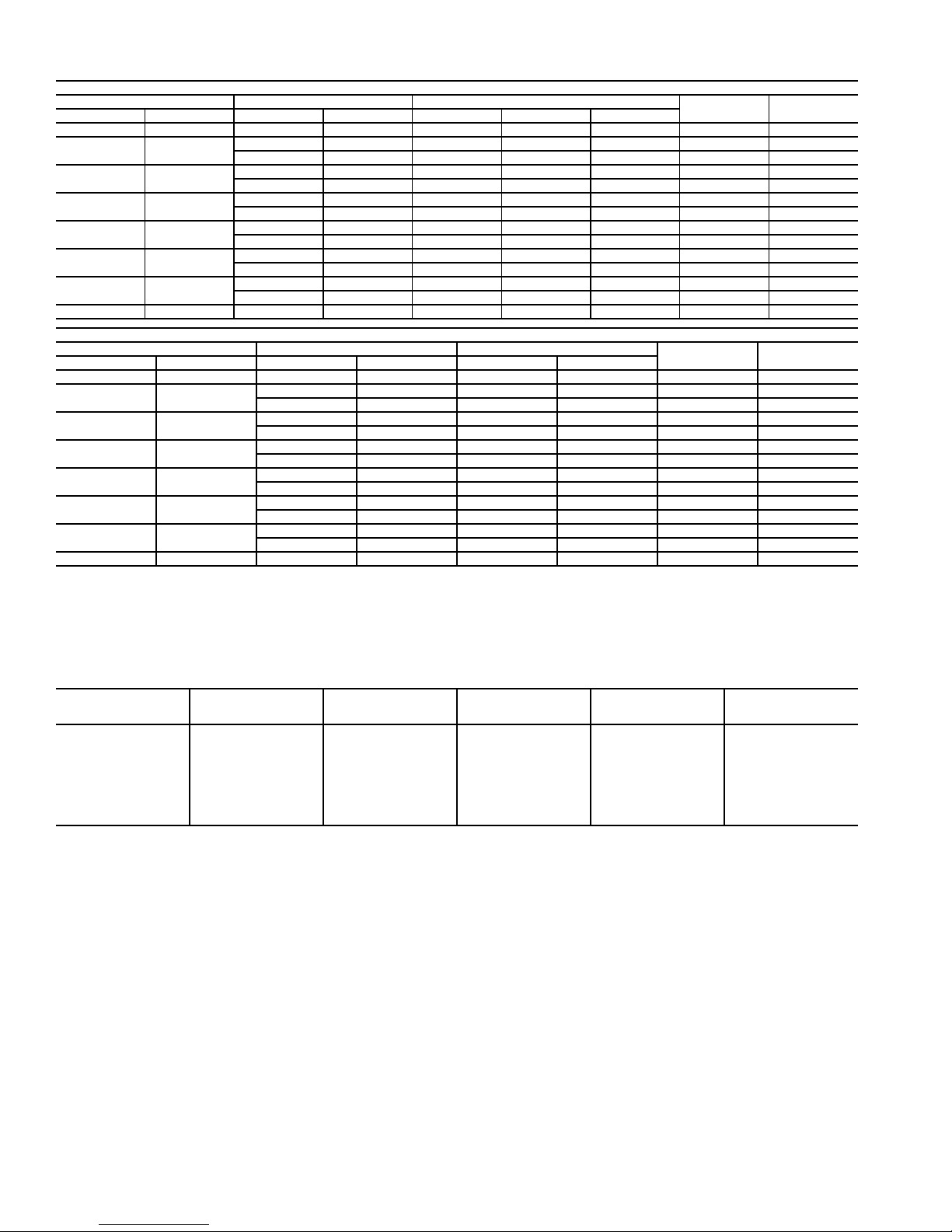
Table 39 — Motor Limitations
Nominal Maximum Maximum Amps
Bhp BkW Bhp BkW 230 v 460 v 575 v
53.735.9 4.40 15.0 7.9 6.0 5,030 87.5
7.5 5.6
10 7.46
15 11.19
20 14.92
25 18.65
30 22.38
40 29.84 42.0 31.33 110.0 55.0 43.8 33,690 93.0
Nominal Maximum Maximum Amps
Bhp BkW Bhp BkW 230 v 460 v
53.735.9 4.40 15.8 7.9 4,918 89.5
7.5 5.6
10 7.46
15 11.19
20 14.92
25 18.65
30 22.38
40 29.84 42.0 31.33 110.0 55.0 33,156 94.5
LEGEND
Bhp — Brake Horsepower
BkW — Brake Kilowatts
NOTES:
1. Extensive motor and electrical testing on the Carrier units has ensured that
the full horsepower range of the motor can be utilized with confidence.
8.7 6.49 23.5 — — 7,717 84.1
9.5 7.09 — 12.0 10.0 8,008 88.5
10.2 7.61 31.0 — — 9,502 89.5
11.8 8.80 — 15.0 12.0 9,836 89.5
15.3 11.41 46.0 — — 12,543 91.0
18.0 13.43 — 22.0 19.0 14,756 91.0
22.4 16.71 60.0 — — 18,363 91.0
23.4 17.46 — 28.7 23.0 19,183 91.0
28.9 21.56 73.0 — — 23,511 91.7
29.4 21.93 — 37.4 28.4 23,918 91.7
35.6 26.56 91.0 — — 28,742 92.4
34.7 25.89 — 43.8 36.3 28,015 92.4
8.7 6.49 23.5 — 7,078 91.7
9.5 7.09 — 12.0 7,728 91.7
10.2 7.61 30.0 — 8,298 91.0
11.8 8.80 — 15.0 9,600 91.7
15.3 11.41 46.0 — 12,273 91.7
18.0 13.43 — 22.0 14,439 93.0
22.4 16.71 59.0 — 17,853 93.0
23.4 17.46 — 28.7 18,650 93.6
28.9 21.56 73.0 — 23,034 93.6
29.4 21.93 — 36.3 23,432 93.6
35.6 26.56 82.6 — 28,374 93.6
34.7 25.89 — 41.7 27,656 93.6
HIGH-EFFICIENCY MOTORS
PREMIUM-EFFICIENCY MOTORS
Using the fan motors up to the horsepower ratings shown in the Motor Limitations table will not result in nuisance tripping or premature motor failures. Unit warranty will not be affected.
2. All motors comply with Energy Policy Act (EPACT) Standards effective
October 24, 1997.
Maximum
Watts
Maximum
Watts
Maximum
Efficiency
Maximum
Efficiency
Table 40A — Air Quantity Limits (48AJ,AK,AW,AY,A2,A3,A4,A5)
UNIT SIZE*
020 5,900 6,100 4,000 6,000 10,000
025 5,900 6,100 5,000 7,500 12,500
027 5,900 6,100 5,400 8,100 13,500
030 5,900 6,100 6,000 9,000 15,000
035 (AJ,AK,AW,AY) 5,900 6,100 7,000 10,500 17,500
035 (A2,A3,A4,A5) 5,900 10,100 7,000 10,500 17,500
036,040,041 7,600 10,100 8,000 12,000 20,000
050 7,600 10,100 10,000 15,000 22,500
051,060 11,000 10,100 12,000 18,000 27,000
LEGEND
CV — Constant Volume
VAV — Variable Air Volume
MINIMUM HEATING
AIRFLOW CFM
(Low Heat)
MINIMUM HEATING
AIRFLOW CFM
(High Heat)
MINIMUM COOLING
AIRFLOW (VAV) CFM
AT FULL LOAD
* Sizes 036,041, and 051 are 48AJ,AK,AW,AY only.
NOTE: Variable air volume units will operate down to 70 cfm/ton in Cooling
mode. Performance at 70 cfm/ton is limited to unloaded operation and may be
also limited by edb (entering dry bulb) and ewb (entering wet bulb) conditions.
MINIMUM COOLING
AIRFLOW CFM
(CV)
MAXIMUM AIRFLOW
CFM
26
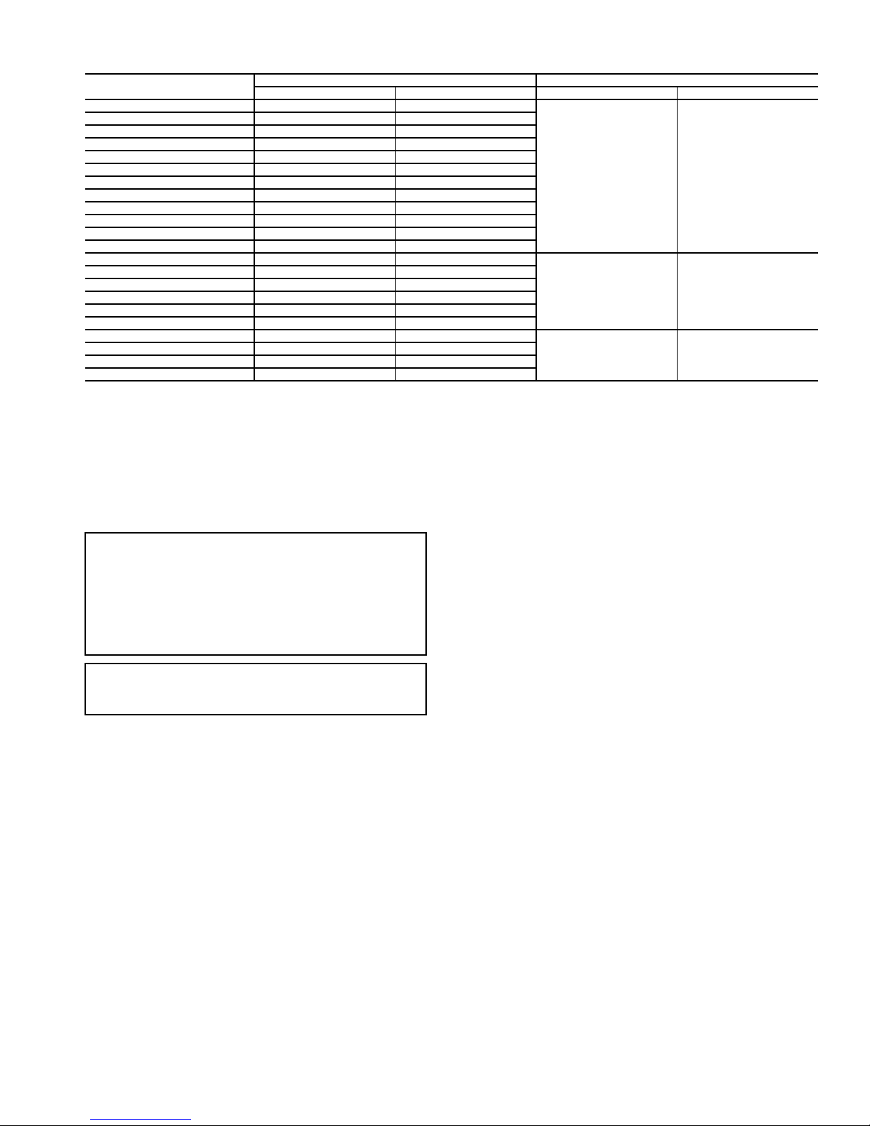
Table 40B — Air Quantity Limits (50AJ,AK,AW,AY,A2,A3,A4,A5)
UNIT
50AJ,AW,A2,A3020 6,000 10,000
50AK,AY,A4,A5020 4,000 10,000
50AJ,AW,A2,A3025 7,500 12,500
50AK,AY,A4,A5025 5,000 12,500
50AJ,AW,A2,A4027 8,100 13,500
50AK,AY,A3,A5027 5,400 13,500
50AJ,AW,A2,A4030 9,000 15,000
50AK,AY,A3,A5030 6,000 15,000
50AJ,AW,A2,A4035 10,500 17,500
50AJ,AW036 10,500 17,500
50AK,AY,A3,A5035 7,000 17,500
50AK,AY036 7,000 17,500
50AJ,AW,A2,A4040 12,000 20,000
50AJ,AW041 12,000 20,000
50AK,AY,A3,A5040 8,000 20,000
50AK,AY041 8,000 20,000
50AJ,AW,A2,A4050 13,500 20,000
50AK,AY,A3,A5050 10,000 20,000
50AJ,AW051 18,000 27,000
50AJ,AW,A2,A4060 18,000 27,000
50AK,AY051 12,000 27,000
50AK,AY,A3,A5060 12,000 27,000
*Operation at these levels may be limited by entering evaporator air wet bulb temperatures.
Min CFM Max CFM* Min CFM Max CFM
COOLING ELECTRIC HEAT
6,000 15,000
10,500 20,000
15,000 27,000
CONTROLS QUICK START
The following section will provide a quick user guide to setting up and configuring the A Series units with ComfortLink™
controls. See Basic Control Usage section on page 3 for information on operating the control. For wiring information, refer
to unit wiring diagrams in the Major System Components section on page 101.
IMPORTANT: The ComfortLink controls provide the user
with numerous configuration options such as set points,
demand levels, reset, and many others. If the building
owner or design engineer has not provided specific recommendations for these configuration settings, it is suggested
that the installer do not make changes to the default factory
settings. The factory-configured default values are appropriate for many applications.
IMPORTANT: The unit is shipped with the unit control
disabled. Enable the control by setting Local Machine Disable (Service Test
STOP) to No.
Two-Stage Constant Volume Units with
Mechanical Thermostat — To configure the unit, per-
form the following:
1. The type of control is configured under Configuration
UNITC.TYP. Set C.TYP to 4 (TSTAT 2 STG).
2. Remove jumpers from R-W2 and W2-W1 on TB4 in the
control box.
3. See Economizer Options section on page 28 for additional economizer option configurations.
4. See Exhaust Options section on page 29 for additional
exhaust option configurations.
Two-Stage Constant Volume Units with Space
Sensor —
1. The type of control is configured under Configuration
2. Under Configuration
the space sensor by setting SPT.S to ENBL (enable).
3. Install jumpers between R-W2 and W2-W1 on TB4 in
the control box.
4. The space temperature set points are configured under the
Setpoints menu. The heating and cooling set points may
To configure the unit, perform the following:
UNITC.TYP. Set C.TYP to 6 (SPT 2 STG).
UNITSENSSPT.S, enable
be configured. See the Heating Control and Cooling
Control sections on pages 50 and 37 for further description on these configurations. The following set points
may be configured:
OHSP Occupied Heat Setpoint
OCSP Occupied Cool Setpoint
UHSP Unoccupied Heat Setpoint
UCSP Unoccupied Cool Setpoint
GAP Heat-Cool Setpoint Gap
5. The degrees of demand from the space temperature set
points are configured under the Configuration
D.LV.T
submenu. See the Heating Control and Cooling Control
sections for further description on these configurations.
The following set points may be configured:
L.H.ON Demand Level Lo Heat On
H.H.ON Demand Level Hi Heat On
L.H.OF Demand Level Lo Heat Off
L.C.ON Demand Level Lo Cool On
H.C.ON Demand Level Hi Cool On
L.C.OF Demand Level Lo Cool Off
6. Under Configuration
UNITCV.FN, set CV.FN to 1
for continuous fan or 0 for automatic fan.
7. To program time schedules, set SCH.N=1 under Config-
uration
CCNSC.OVSCH.N to configure the
control to use local schedules.
8. Under the Timeclock
SCH.L submenu, enter the
desired schedule. See Time Clock Configuration section
on page 75 for further description of these configurations.
9. Under the Configuration
CCNSC.OV submenu, the
following schedules and overrides should be configured:
O.T.L. Override time limit
SPT.O SPT override enabled?
T58.O T58 override enabled?
10. See Economizer Options section on page 28 for additional economizer option configurations.
11. See Exhaust Options section on page 29 for additional
exhaust option configurations.
27

Variable Air Volume Units Using Return Air
Sensor or Space Temperature Sensor —
figure the unit, perform the following:
1. The type of control is configured under Configuration
UNITC.TYP. Set C.TYP to 1 (VAV-RAT) for return
air sensor. Set C.TYP to 2 (VAV-SPT) for space temperature sensor.
NOTE: For VAV with a space sensor (VAV-SPT), under
Configuration
space sensor by setting SPT.S to ENBL.
2. Install jumpers between R-W2 and W2-W1 on TB4 in
the control box.
3. The space temperature set points and the supply air set
points are configured under the Setpoints menu. The
heating and cooling set points must be configured. See
the Heating Control and Cooling Control sections for
further description on these configurations. Configure the
following set points:
OHSP Occupied Heat Setpoint
OCSP Occupied Cool Setpoint
UHSP Unoccupied Heat Setpoint
V. C . O N VAV Occupied Cool On Delta
V. C . O F VAV Occupied Cool Off Delta
SASP Supply Air Setpoint
4. To program time schedules, make sure SCH.N=1 under
Configuration
the control to use local schedules.
5. Under the Timeclock
sired schedule. See Time Clock Configuration section on
page 75 for further description of these configurations.
6. Under Configuration
ic Pressure Setpoint should be configured.
SP.SP Static Pressure Setpoint
7. If supply air temperature reset is desired, under the
Configuration
points should be configured:
RS.CF EDT Reset Configuration
RTIO Reset Ratio (if RS.CF = 1 or 2)
LIMT Reset Limit (if RS.CF = 1 or 2)
RES.S EDT 4-20 mA Reset Input (if RS.CF = 3)
NOTE: Configure either RTIO and LIMT or RES.S. All three
are not used.
8. See the Economizer Options section on this page for additional economizer option configurations.
9. See the Exhaust Options section on page 29 for additional
exhaust option configurations.
UNITSENSSPT.S, enable the
CCNSC.OVSCH.N to configure
SCH.L submenu, enter the de-
SP
EDT.R submenu, the following set
SP.SP, the supply duct Stat-
To con-
Multi-Stage Constant Volume Units with
Mechanical Thermostat —
form the following:
1. Under Configuration
(TSTAT MULTI).
2. Remove jumpers from R-W2 and W2-W1 on TB4 in the
control box. Connect thermostat to TB4.
3. Under the Setpoints menu, set the following
configurations:
SA.HI Supply Air Set Point Hi
SA.LO Supply Air Set Point Lo
4. See the Economizer Options section on this page for additional economizer option configurations.
To configure the unit, per-
UNITC.TYP, set C.TYP to 3
5. See the Exhaust Options section on page 29 for additional
exhaust option configurations.
Multi-Stage Constant Volume Units with
Space Sensor —
following:
1. Under Configuration
(SPT MULTI).
2. Install jumpers between R-W2 and W2-W1 on TB4 in
the control box.
3. Under the Setpoints menu, the following configurations
should be set:
OHSP Occupied Heat Setpoint
OCSP Occupied Cool Setpoint
UHSP Unoccupied Heat Setpoint
UCSP Unoccupied Cool Setpoint
GAP Heat-Cool Setpoint Gap
SA.HI Supply Air Set Point Hi
SA.LO Supply Air Set Point Lo
4. The degrees of demand from the space temperature set
points are configured under the Configuration
submenu. See the Heating Control and Cooling Control
sections for further description on these configurations.
Configure the following set points:
L.H.ON Demand Level Lo Heat On
H.H.ON Demand Level Hi Heat On
L.H.OF Demand Level Lo Heat On
L.C.ON Demand Level Lo Cool On
H.C.ON Demand Level Hi Cool On
L.C.OF Demand Level Lo Cool On
5. Under Configuration
the space sensor by setting SPT.S to ENBL.
6. Under Configuration
for continuous fan or 0 for automatic fan.
7. To program time schedules, set SCH.N=1 under Config-
uration
trol to use local schedules.
8. Under the Timeclock
sired schedule. See Time Clock Configuration section on
page 75 for further description of these configurations.
9. See the Economizer Options section below for additional
economizer option configurations.
10. See the Exhaust Options section on page 29 for additional
exhaust option configurations.
CCNSC.OVSCH.N to configure the con-
Economizer Options — Under the Configuration
ECON submenu, the following set points may be configured:
EC.EN Economizer Enabled?
EC.MN Economizer Min.Position
EC.MX Economizer Maximum Position
E.TRM Economizer Trim for SumZ?
E.SEL Econ Changeover Select
OA.E.C OA Enthalpy Change Over Select
OA.EN Outdoor Enthalpy Compare Value
OAT.L High OAT Lockout Temp
O.DEW OA Dew Point Temp Limit
ORH.S Outside Air RH Sensor
Configuration
the minimum damper position.
To configure the unit, perform the
UNITC.TYP, set C.TYP to 5
D.LV.T
UNITSENSSPT.S, enable
UNITCV.FN, set CV.FN to 1
SCH.L submenu, enter the de-
ECONEC.MN should always be set for
28

Indoor Air Quality (IAQ) Options
DEMAND CONTROLLED VENTILATION — Under
Configuration
parameters should be set to establish the minimum and maximum points for outdoor air damper position during demand
controlled ventilation (DCV):
EC.MN Economizer Min.Position
IAQ.M IAQ Demand Vent Min.Pos.
Configuration
absolute minimum vent position (or maximum reset) under
DCV.
Configuration
minimum damper position (or with no DCV reset). This is also
referenced in the economizer section.
IAQDCV.C, the following configuration
IAQDCV.CIAQ.M is used to set the
IAQDCV.CEC.MN is used to set the
Exhaust Options — The A Series units can be config-
ured with constant volume 2-stage power exhaust or modulating power exhaust. The following exhaust options should be
configured.
Configuration
Option) — For two-stage exhaust, under the Configuration
BP submenu, configure the following:
BP.P1 Power Exhaust On Setp.1
BP.P2 Power Exhaust On Setp.2
Configuration
Option) — For modulating exhaust, in the Configuration
BP submenu, configure the following:
BP.SP Building Pressure Setp.
BP
BP
BF.CF=1 (Two-Stage Exhaust
BF.CF=2 (Modulating Power Exhaust
Programming Operating Schedules — The
ComfortLink™ controls will accommodate up to eight different schedules (Periods 1 through 8), and each schedule is
assigned to the desired days of the week. Each schedule
includes an occupied on and off time. As an example, to set an
occupied schedule for 8 AM to 5 PM for Monday through
Friday, the user would set days Monday through Friday to ON
for Period 1. Then the user would configure the Period 1
Occupied From point to 08:00 and the Period 1 Occupied To
point to 17:00. To create a different weekend schedule, the user
would use Period 2 and set days Saturday and Sunday to ON
with the desired Occupied On and Off times. To create a schedule, perform the following procedure:
NOTE: By default, the time schedule periods are programmed
for 24 hours of occupied operation.
1. Scroll to the Configuration mode, and select CCN
CONFIGURATION (CCN). Scroll down to the Schedule
Number (Configuration
password protection has been enabled, the user will be
prompted to enter the password before any new data is
accepted. SCH.N has a range of 0 to 99. The default value is 1. A value of 0 is always occupied, and the unit will
control to its occupied set points. A value of 1 means the
unit will follow a local schedule, and a value of 65 to 99
means it will follow a CCN schedule. Schedules 2 to 64
are not used as the control only supports one internal/local schedule. If one of the 2 to 64 schedules is configured,
then the control will force the number back to 1. Make
sure the value is set to 1 to use a local schedule.
2. Enter the Time Clock mode. Scroll down to the LOCAL
TIME SCHEDULE (SCH.L) sub-mode, and press
ENTER. Period 1 (PER.1) will be displayed. Press ENTER to configure Period 1.
3. Configure the beginning of the occupied time period for
Period 1 (OCC). Scroll down to OCC and press ENTER
to go into Edit mode. The first two digits of the 00.00 will
start flashing. Use the UP or DOWN key to display the
CCNSC.OVSCH.N). If
correct value for hours, in 24-hour (military) time. Press
ENTER and hour value is saved and the minutes digits
will start flashing. Use the same procedure to display and
save the desired minutes value. Press ESCAPE.
4. Configure the unoccupied time for period 1 (UNC).
Scroll down to UNC and press ENTER to go into Edit
mode. The first two digits of the 00.00 will start flashing.
Use the UP or DOWN key to display the correct value for
hours, in 24-hour (military) time. Press ENTER and hour
value is saved and the minutes digits will start flashing.
Use the same procedure to display and save the desired
minutes value. Press ESCAPE.
5. Scroll to DAYS and press ENTER. Scroll down to the
MON point. This point indicates if schedule 1 applies to
Monday. Use the ENTER command to go into Edit
mode, and use the UP or DOWN key to change the display to YES or NO. Scroll down through the rest of the
days and apply schedule 1 where desired. The schedule
can also be applied to a holiday. Press ESCAPE.
6. The first schedule is now complete. If a second schedule
is needed, such as for weekends or holidays, scroll down
and repeat the entire procedure for period 2 (PER.2). If
additional schedules are needed, repeat the process for as
many as are needed. Eight schedules are provided.
SERVICE TEST
General —
ture, which is intended to allow a service person to force the
unit into different modes of operation to test them. To use this
feature, enter the Service Test category on the local display and
place the unit into the test mode by changing Service
Te st
TEST from OFF to ON. The display will prompt for the
password before allowing any change. The default password is
1111. Once the unit enters the Service Test mode, the unit will
shut down all current modes.
TEST — The TEST command turns the unit off (hard stop)
and allows the unit to be put in a manual control mode.
STOP — The STOP command completely disables the unit
(all outputs turn off immediately). Once in this mode, nothing
can override the unit to turn it on. The controller will ignore all
inputs and commands.
S.STP — Setting Soft Stop to YES turns the unit off in an
orderly way, honoring any time guards currently in effect.
FAN. F — By turning the FAN FORCE on, the supply fan is
turned on and will operate as it normally would, controlling
duct static pressure on VAV applications or just energizing the
fan on CV applications. To remove the force, press ENTER
and then press the UP and DOWN arrows simultaneously.
F. 4 . C H — The 4-Inch Filter Change Mode variable is used to
service the unit when 4-in. filters are used. When the filters
need to be changed, set Service Test
will be placed in Service Test mode and the economizer will
move to the 40% open position to facilitate removal of the 4-in.
filters. After the filters have been changed, set Service
Te st
F. 4 . C H = NO to return the unit to normal operation.
The remaining categories: INDP, FANS, COOL, and
HEAT are sub-modes with separate items and functions. See
Table 41.
The units are equipped with a Service Test fea-
F. 4 . C H = YES. The unit
Service Test Mode Logic — Operation in the Service
Test mode is sub-mode specific except for the Independent submode. Leaving the sub-mode while a test is being performed
and attempting to start a different test in the new sub-mode will
cause the previous test to terminate. When this happens, the
new request will be delayed for 5 seconds. For example, if compressors were turned on under the COOL sub-mode, any attempt to turn on heating stages within the HEAT sub-mode
would immediately turn off the compressors and, 5 seconds later, the controller would honor the requested heat stages.
29

However, it is important to note that the user can leave a
Service Test mode to view any of the local display modes and
the control will remain in the Service Test mode.
Independent Outputs — The INDP sub-mode items
can be turned on and off regardless of the other category states.
For example, the alarm relay can be forced on in the INDP
sub-mode and will remain on if compressor relays are requested in the COOL sub-mode.
Fans in Service Test Mode — Upon entering the
FA NS sub-mode, the user will be able to turn the supply fan on
and off, set the supply fan VFD speed, and turn the condenser
fans on and off.
Cooling in Service Test Mode — The COOL sub-
mode offers different cooling service tests.
The user has manual relay control of individual compressors. If the user energizes mechanical cooling, the supply fan
and the outdoor fans will be started automatically. During
mechanical cooling, the unit will protect itself. Compressor
diagnostics are active, monitoring for high discharge pressure,
low suction pressure, etc. The user can also turn the hot gas
bypass valve on and off.
NOTE: It is crucial that proper compressor rotation be verified
during the service test. Each compressor must be tested
individually. After starting each compressor, the control will
check the suction pressure after 5 seconds of run time. If the
control does not see a sufficient decrease in suction pressure
after 5 seconds, mechanical cooling will be shut down, and an
alarm will be generated (A140). This alarm requires a manual
reset. If this alarm occurs, do not attempt a restart of the
compressor and do not attempt to start any other compressors
until the wiring to the unit has been corrected.
Heating in Service Test Mode — If unit has a ther-
mostat connected (C.TYP = 3 or 4), install the RED jumper
wires between TB4, terminals R (1), W2 (3) and W1 (4). Terminal block TB4 is located in the unit control box. Remember
to disconnect these jumpers when Test Mode is completed. The
Heat Test Mode sub-mode will offer automatic fan start-up if
the unit is not a gas heat unit. On gas heat units, the IGC feedback from the gas control units will bring the fan on as
required.
Within this sub-mode, the user has control of heat relays 1
to 6. The user can also turn on the requested heat stage.
NOTE: When service test has been completed, if unit has a
thermostat connected (C.TYP = 3 or 4), remove the RED
jumper wires at TB4, terminals R (1), W2 (3) and W1 (4).
Terminal block TB4 is located in the unit control box. Store
these jumpers in the unit control box for future use.
Table 41 — Service Test
ITEM EXPANSION RANGE UNITS POINT WRITE STATUS
TEST Service Test Mode ON/OFF MAN_CTRL
STOP Local Machine Disable YES/NO UNITSTOP config
S.STP Soft Stop Request YES/NO SOFTSTOP forcible
FAN.F Supply Fan Request YES/NO SFANFORC forcible
F.4 . CH 4 in. Filter Change Mode YES/NO FILT4CHG
INDP TEST INDEPENDENT OUTPUTS
ECON Economizer Act.Cmd.Pos. ECONCTST
E.PWR Economizer Power Test ECONPTST
E.CAL Calibrate the Economizer? ECON_CAL
E.VFD Exhaust Fan VFD Speed 0-100 % EFAN_VFD
PE.A Power Exhaust Relay A PE_A_TST
PE.B Power Exhaust Relay B PE_B_TST
PE.C Power Exhaust Relay C PE_C_TST
H.I.R Heat Interlock Relay ON/OFF HIR_TST
ALRM Remote Alarm/Aux Relay ON/OFF ALRM_TST
FANS TEST FANS
S.FAN Supply Fan Relay ON/OFF SFAN_TST
S.VFD Supply Fan VFD Speed 0-100 % SGVFDTST
CD.F.A Condenser Fan Circuit A ON/OFF CNDA_TST
CD.F.B Condenser Fan Circuit B ON/OFF CNDB_TST
COOL TEST COOLING
A1 Compressor A1 Relay ON/OFF CMPA1TST
A2 Compressor A2 Relay ON/OFF CMPA2TST
MLV Min. Load Valve (HGBP) ON/OFF MLV_TST
B1 Compressor B1 Relay ON/OFF CMPB1TST
B2 Compressor B2 Relay ON/OFF CMPB2TST
HEAT TEST HEATING
HT.ST Requested Heat Stage 0-MAX HTST_TST
HT.1 Heat Relay 1 ON/OFF HS1_TST
HT.2 Heat Relay 2 ON/OFF HS2_TST
HT.3 Relay 3 W1 Gas Valve 2 ON/OFF HS3_TST
HT.4 Relay 4 W2 Gas Valve 2 ON/OFF HS4_TST
HT.5 Relay 5 W1 Gas Valve 3 ON/OFF HS5_TST
HT.6 Relay 6 W2 Gas Valve 3 ON/OFF HS6_TST
30

THIRD PARTY CONTROL
Thermostat —
the thermostat inputs:
Y1 = first stage cooling
Y1 and Y2 = first and second stage cooling
W1 = first stage heating
W1 and W2 = first and second stage heating
G = supply fan
The method of control would be through
Alarm Output — The alarm output TB4-7 and 8, will pro-
vide relay closure whenever the unit is under an alert or alarm
condition.
Remote Switch — The remote switch may be configured
for three different functions. Under ConfigurationUNIT, set
RM.CF to one of the following:
0 = no remote switch
1 = occupied/unoccupied switch
2 = start/stop switch
3 = occupancy override switch
With RM.CF set to 1, no time schedules are followed and
the unit follows the remote switch only in determining the state
of occupancy.
With RM.CF set to 2, the remote switch can be used to shut
down and disable the unit, while still honoring time guards on
compressors. Time schedules, internal or external, may be run
simultaneously with this configuration.
With RM.CF set to 3, the remote input may override an
unoccupied state and force the control to go into occupied
mode. As with the start/stop configuration, an internal or external time schedule may continue to control occupancy when the
switch is not in effect.
Under Configuration
pancy switch can be set to either a normally open or normally
closed switch input. Normal is defined as either unoccupied, start
or “not currently overridden,” respective to the RM.CF
configuration.
SW.LGRMI.L, the remote occu-
VFD Control — On VFD equipped supply fans, supply
duct static pressure control may be left under unit control or be
externally controlled. To control a VFD externally with a 4 to
20 mA signal, set SP.RS to 4, under the Configuration
menu. This will set the reset to VFD control. When SP.RS = 4,
the static pressure reset function acts to provide direct VFD
speed control where 4 mA = 0% speed and 20 mA = 100%
(SP.MN and SP.MX will override). Note that SP.CF must be
set to 1 (VFD Control) prior to configuring SP.RS = 4. Failure
to do so could result in damage to ductwork due to overpressurization. In effect, this represents a speed control signal “pass
through” under normal operating circumstances. The Com-
fortLink controller overrides the third party signal for critical
operation situations, most notably smoke and fire control. Wire
the input to the controls expansion module (CEM) using TB-11
and 12. An optional CEM board is required.
See Appendix C and the VFD literature supplied with the unit
for VFD configurations and field wiring connections to the VFD.
SP
Supply Air Reset — With the installation of the CEM,
the ComfortLink controller is capable of accepting a 4 to
20 mA signal, to reset the supply-air temperature up to a maximum of 20 F. See VFD Control section above.
Demand Limit Control — The term “demand limit
control” refers to the restriction of the machine’s mechanical
cooling capacity to control the amount of power that a machine
may use.
Demand limiting using mechanical control is possible via two
means:
Two discrete inputs tied to demand limit set point percentages.
OR
A 4 to 20 mA input that can reduce or limit capacity linearly to
a set point percentage.
In either case, it will be necessary to install a controls ex-
pansion module (CEM).
DEMAND LIMIT DISCRETE INPUTS — First, set DM.L.S
in Configuration
When Inputs
OFF, the control will not set any limit to the capacity, and
when ON, the control sets a capacity limit to the Configura-
tion
DMD.LD.L.S1 set point.
Likewise, when Inputs
no. 2) is OFF, the control will not set any limit to the capacity,
and when ON, the control sets a capacity limit to the Configu-
ration
DMD.LD.L.S2 set point.
If both switches are ON, Inputs
as the limiter of capacity.
Under Configuration
ately for the action desired. Set the DL1.L and DL2.L configurations. They can be set normally open or normally closed. For
example, if DL1.L is set to OPEN, the user will need to close
the switch to cause the control to limit capacity to the demand
limit 1 set point. Likewise, if DL1.L is set to CLSE (closed),
the user will need to open the switch to cause the control to
limit capacity to the demand limit 1 set point.
DEMAND LIMIT 4 TO 20 mA INPUT — Under Configu-
ration
20 mA control). Under the same menu, set D.L.20 to a value
from 0 to 100% to set the demand limit range. For example,
with D.L.20 set to 50, a 4 mA signal will result in no limit to
the capacity and 20 mA signal will result in a 50% reduction in
capacity.
DMD.L, set configuration DM.L.S to 2 (2 = 4 to
DMD.L to 1 (2 switches).
GEN.IDL.S1 (Demand Switch no. 1) is
GEN.IDL.S2 (Demand Switch
GEN.IDL.S2 is used
SW.LG, set the logic state appropri-
Demand Controlled Ventilation Control —
There are multiple methods for externally controlling the economizer damper.
IAQ DISCRETE INPUT CONFIGURATION — The IAQ discrete input configuration requires a CEM module (optional) to
be installed and an interface to a switch input at TB5-13 and
14. The state of the input on the display can be found at
Inputs
AIR.QIAQ.I.
Before configuring the switch functionality, first determine
how the switch will be read. A closed switch can indicate either
a low IAQ condition or a high IAQ condition. This is set at
Configuration
low reading would mean based on the type of switch being
used. Setting IAQ.L to OPEN means that when the switch is
open the input will read LOW. When the switch is closed, the
input will read HIGH. Setting IAQ.L to CLSE (closed) means
that when the switch is closed the input will read LOW, and
therefore, when the switch is open the switch will read HIGH.
There are two possible configurations for the IAQ discrete
input. Select item Configuration
and configure for either 1 (IAQ Discrete) or 2 (IAQ Discrete
Override).
IQ.I.C
Discrete), and the switch logic (Configuration
IAQ.L) is set to OPEN, then an open switch reads low and a
closed switch reads high.
If the switch is open, the economizer will be commanded to
the IAQ Demand Vent Minimum Position.
These settings may be adjusted and are located at Configura-
tion
IAQDCV.CIAQ.M.
If the switch is closed, the IAQ reading will be high and the
economizer will be commanded to the Economizer Minimum
Position.
This setting may be adjusted and is located at Configura-
tion
IAQDCV.CEC.MN.
SW.LG and IAQ.L. The user can set what a
IAQAQ.CFIQ.I.C
= 1 (IAQ Discrete) — If the user sets IQ.I.C to 1 (IAQ
SW.LG
31

IQ.I.C
= 2 (IAQ Discrete Override) — If the user sets IQ.I.C
to 2 (IAQ Discrete Override), and Configuration
IAQ.L is set to OPEN, then an open switch reads low and a
closed switch reads high.
If the switch reads low, no action will be taken. If the switch
reads high, the economizer will immediately be commanded to
the IAQ Economizer Override Position. This can be set from 0
to 100% and can be found at Configuration
IQ.O.P.
FAN CONTROL FOR THE IAQ DISCRETE INPUT —
Under Configuration
crete Input Fan Configuration) must also be set. There are
three configurations for IQ.I.F. Select the configuration which
will be used for fan operation. This configuration allows the
user to decide (if the supply fan is not already running),
whether the IAQ discrete switch will start the fan, and in which
state of occupancy the fan will start.
IQ.I.F = 0 Minimum Position Override Switch input
IQ.I.F = 1 Minimum Position Override Switch input
IQ.I.F = 2 Minimum Position Override Switch input
IAQ ANALOG INPUT CONFIGURATION — This input is
an analog input located on the main base board (MBB). There
are 4 different functions for this input. The location of this configuration is at Configuration
The functions possible for IQ.A.C are:
• 0 = no IAQ analog input
• 1 = IAQ analog input
• 2 = IAQ analog input used to override to a set position
• 3 = 4 to 20 mA 0 to 100% economizer minimum position
control
• 4 = 0 to 10 kilo-ohms 0 to 100% economizer minimum
position control
Options 2, 3, and 4 are dedicated for third party control.
IQ.A.C
= 2 (IAQ Analog Input Used to Override) — Under
Configuration
Override Position). The IQ.O.P configuration is adjustable
from 0 to 100%. These configurations are also used in conjunction with Configuration
20 mA Fan Configuration). There are three configurations for
IQ.A.F and they follow the same logic as for the discrete input.
This configuration allows the user to decide (if the supply fan is
not already running), if the IAQ Analog Minimum Position
Override input will start the fan, and in which state of occupancy the fan will start.
IQ.A.F = 0 IAQ analog sensor input cannot start the
IQ.A.F = 1 IAQ analog sensor input can start the supply
IQ.A.F = 2 IAQ analog sensor input can start the supply
If IQ.A.F is configured to request the supply fan, then
configurations D.F.ON and D.F.OF need to be set. These
configuration settings are located under Configuration
IAQAQ.SP and configure the fan override operation based
on the differential air quality (DAQ). If DAQ rises above
D.F.ON, the control will request the fan on until DAQ falls be-
low D.F.OF.
NOTE: If D.F.ON is configured below DAQ.H, the unit is in
occupied mode, and the fan was off, then DAQ rose above
D.F.ON and the fan came on, the economizer will go to the
economizer minimum position (EC.MN).
IAQAQ.CF, the IQ.I.F (IAQ Dis-
will not start fan
will start fan in occupied mode only
will start fan in both occupied and unoccupied modes
IAQAQ.CFIQ.A.C.
IAQAQ.SP, set IQ.O.P (IAQ Economizer
IAQAQ.CFIQ.A.F (IAQ 4 to
supply fan
fan in occupied mode only
fan in both occupied and unoccupied modes
SW.LG
IAQAQ.SP
The 4 to 20 mA signal from the sensor wired to TB5-6 and
7 is scaled to an equivalent indoor CO
ters IQ.R.L and IQ.R.H located under the Configuration
IAQAQ.S.R menu. The parameters are defined such that
4 mA = IQ.R.L and 20 mA = IQ.R.H. When the differential air
quality DAQ (IAQ – OAQ.U) exceeds the DAQ.H set point
(Configuration
on, the economizer minimum vent position (Configuration
IAQDCV.CEC.MN) is overridden and the damper is
moved to the IQ.P.O configuration. When the DAQ falls below
the DAQ.L set point (Configuration
the economizer damper is moved back to the minimum vent
position (EC.MN).
NOTE: Configuration OAQ.U is used in the calculation of the
trip point for override and can be found under Configura-
tion
IAQAQ.SP.
IQ.A.C
= 3 (4 to 20 mA Damper Control) — This configuration will provide full 4 to 20 mA remotely controlled analog input for economizer minimum damper position. The 4 to 20 mA
signal is connected to terminals TB5-6 and 7. The input is
processed as 4 mA = 0% and 20 mA = 100%, thereby giving
complete range control of the effective minimum position.
The economizer sequences can be disabled by setting Con-
figuration
economizer damper position is then possible by using a 4 to
20 mA economizer minimum position control or a 0 to
10 kilo-ohm 0 to 100% economizer minimum position control
via configuration decisions at Configuration
IQ.A.C.
IQ.A.C
= 4 (10 Kilo-ohm Potentiometer Damper Control)
— This configuration will provide input for a 10 kilo-ohm linear potentiometer that acts as a remotely controlled analog input for economizer minimum damper position. The input is
processed as 0 ohms = 0% and 10,000 ohms = 100%, thereby
giving complete range control of the effective minimum
position.
IAQAQ.SP menu) and the supply fan is
ECONE.SEL to 0. Complete control of the
(IAQ) by the parame-
2
IAQAQ.SP menu),
IAQAQ.CF
CONTROLS OPERATION
Modes —
hierarchy of command structure as defined by three essential
elements: the System mode, the HVAC mode and the Control
mode. The System mode is the top level mode that defines three
essential states for the control system: OFF, RUN and TEST.
The HVAC mode is the functional level underneath the
System mode which further defines the operation of the
control. The mode selection process is shown in Appendix D.
The Control mode is essentially the control type of the unit
(Configuration
the control looks to establish a cooling or heating mode and
whether 2 stages or multiple stages of cooling capacity operation are controlled.
Furthermore, there are a number of modes which operate
concurrently when the unit is running. The operating modes of
the control are located at the local displays under Operating
Modes. See Table 42.
Currently Occupied (
rent occupied state of the unit.
Timed Override in Effect (
if the state of occupancy is currently occupied due to an
override.
DCV Resetting Minimum Position (
displays if the economizer position has been lowered from its
maximum vent position.
The ComfortLink™ controls operate under a
UNITC.TYP). This defines from where
OCC) — This variable displays the cur-
T. OV R) — This variable displays
DCV) — This variable
32

Table 42 — Operating Modes Display Table
ITEM EXPANSION RANGE CCN POINT
SYS.M ascii string n/a
HVAC ascii string n/a
CTRL ascii string n/a
MODE MODES CONTROLLING UNIT
OCC Currently Occupied ON/OFF MODEOCCP
T.OVR Timed Override in Effect ON/OFF MODETOVR
DCV DCV Resetting Min Pos ON/OFF MODEADCV
SA.R Supply Air Reset ON/OFF MODESARS
DMD.L Demand Limit in Effect ON/OFF MODEDMLT
T.C.ST Temp.Compensated Start ON/OFF MODETCST
IAQ.P IAQ Pre-Occ Purge Active ON/OFF MODEIQPG
LINK Linkage Active — CCN ON/OFF MODELINK
LOCK Mech.Cooling Locked Out ON/OFF MODELOCK
H.NUM HVAC Mode Numerical Form number MODEHVAC
Supply Air Reset (
SA.R) — This variable displays if the sup-
ply air reset is currently active. This applies to cooling only.
Demand Limit in Effect (
DMD.L) — This variable displays
if the mechanical cooling capacity is currently being limited or
reduced by an outside third party.
Temperature Compensated Start (
T.C. ST ) — This variable
displays if Heating or Cooling has been initiated before the
occupied period to pre-condition the space.
IAQ Pre-Occupancy Purge Active (
IAQ.P) — This variable
displays if the economizer is open and the fan is on to preventilate the building before occupancy.
Linkage Active CCN (
LINK) — This variable displays if a
linkage master in a zoning system has established “linkage”
with this air source (rooftop).
Mechanical Cooling Locked Out (
LOCK) — This variable
displays if mechanical cooling is currently being locked due to
low outside air temperature.
HVAC Mode Numerical Form (
H.NUM) — This is a numerical representation of the HVAC modes which may be read via
a point read.
SYSTEM MODES (Operating Modes
System Mode Off
— When the system mode is OFF, all out-
SYS.M)
puts are to be shut down and no machine control is possible.
The following list displays the text assigned to the System
Mode when in the OFF mode and the conditions that may
cause this mode are checked in the following hierarchal order:
1. Wake up timer on a power reset.
(“Initializing System ...”)
2. System in the process of shutting down compressors and
waiting for timeguards to expire.
(“Shutting Down ...”)
3. Factory shut down (internal factory control level —
SHUTDOWN).
(“Factory Shut Down”)
4. Unit stop (software application level variable that acts as
a hard shut down — Service Test
STOP).
(“Local Machine Stop”)
5. Fire shut down (traumatic fire shutdown condition based
on the Fire Shutdown Input — Inputs
FIREFSD).
(“Fire-Shutdown Mode”)
6. Emergency stop, which is forced over the CCN through
the Emergency Stop Variable (EMSTOP).
(“CCN Emergency Stop”)
7. Startup delay.
(“Startup delay = 0-900 secs”)
8. Service test ending transition timer.
(“Service Test Ending”)
9. Unexplained internal software failure.
(“Internal Failure”)
System Mode Test
— When the system mode is Test, the control is limited to the Test mode and is controllable via the local
displays (scrolling marquee and Navigator™ display) or
through the factory service test control. The System Test
modes are Factory Test Enabled and Service Test Enabled. See
the Service Test Mode section for details on test control in this
mode.
1. Factory Test mode
(“Factory test enabled”)
2. Service Test mode
(“Service test enabled”)
System Mode Run
— When the system mode is Run, the software application in the control is free to run the HVAC control
routines by which cooling, heating, IAQ, etc., is possible. There
are two possible text displays for this mode, one is normal run
mode and the other occurs if one of the following fire-smoke
modes is present: smoke purge, pressurization or evacuation.
1. Normal run time state
(“Unit Operation Enabled”)
2. Fire-Smoke control mode
(“Fire-Smoke Control”)
HVAC MODES (Operating Mode
HVAC) — The system
mode must be selected before the unit controls can select the
HVAC mode of the rooftop unit. The selection of an HVAC
mode is based on a hierarchal decision making process. Certain
overrides may interfere with this process and the normal temperature/humidity control operation of the unit. The decision
making process that determines the HVAC mode is shown in
Fig. 4 and Appendix D.
Each HVAC Mode is described below. The HVAC mode
number is shown in parenthesis after the mode.
HVAC Mode — STARTING UP (0)
— The unit is transi-
tioning from the OFF mode to a different mode.
HVAC Mode — DISABLED (1)
— The unit is shut down
due to a software command disable through the scrolling marquee, a CCN emergency stop command, a service test end, or a
control-type change delay.
HVAC Mode — SHUTTING DOWN (2)
— The unit is tran-
sitioning from a mode to the OFF mode.
HVAC Mode — SOFTSTOP REQUEST (3)
— The unit is
off due to a soft stop request from the control.
HVAC Mode — REM SW.DISABLE (4)
— The unit is off
due to the remote switch.
HVAC Mode — FAN STATUS FAIL (5)
— The unit is off
due to failure of the fan status switch.
HVAC Mode — STATIC PRESSURE FAIL (6)
— The unit is
off due to failure of the static pressure sensor.
HVAC Mode — COMP.STUCK ON (7)
— The unit is shut
down because there is an indication that a compressor is running even though it has been commanded off.
HVAC Mode — OFF (8)
— The unit is off and no operating
modes are active.
HVAC Mode — TEST
(9) — The unit is in the self test mode
which is entered through the Service Test menu.
HVAC Mode — TEMPERING VENT
(10) — The economizer is at minimum vent position but the supply-air temperature has dropped below the tempering vent set point. Staged
gas heat is used to temper the ventilation air.
HVAC Mode — TEMPERING LOCOOL
(11) — The economizer is at minimum vent position but the combination of the
outside-air temperature and the economizer position has
dropped the supply-air temperature below the tempering cool
set point. Staged gas heat is used to temper the ventilation air.
33

System Mode =
Fig. 4 — Mode Selection
A48-8268
OFF?
Yes
Inputs -> FIRE - >
FSD in ala rm?
No
System
Mode
No
HVAC Mode = OFF
(Disabled)
Fire-
Smoke
Control
Unit not in fa ctory
test AND fire-smoke
control mode is
alarm ing?
Yes
Inputs -> FIRE ->
PRES in ala rm?
No
No No
Inputs -> FIRE ->
EVAC in alarm ?
Yes
HVAC Mode = OFF
(Fire Shutdown)
Exceptions
HVAC Mode = OFF
Config->UNIT->
C.TYP cha nged
while unit running?
15-second dela y
(Disabled)
Config->SP-> SP. CF
HVAC Mode = OFF
HVAC Mode = OFF
(Pressurization)
No
No
2
OR
= 1
and static pressure
sensor has failed
Yes Yes Yes Yes
(Static Pres. Fail)
System Mode =
TEST?
HVAC Mode = TEST
Config->UNIT->
SFS.M=1 OR 2 AND
Config->UNIT->
SFS.S=Y ES?
and supply fan
has failed
HVAC Mode = OFF
(Fan Stat us Fail)
No
No
Service Test ->
S.STP = YES ?
HVAC Mode = SoftStop
Reques t
Unit just waking u p
from power reset?
HVAC Mode = OFF
(Starting Up)
Yes
HVAC Mode = OFF
(Evacuation)
Config->UNIT->
RM.CF =2 AN D
Inputs->GEN .I->
REMT = O N
YesYesYesYes
HVAC Mode = OFF
(Rem. Sw. Disable)
No No
Unit shutting down?
HVAC Mode = Sh utting
Down
Yes
No
HVAC Mode = O FF
(Purge)
Unit control free to select
normal heating/cooli ng
HVAC mode
Unit
control free
to choose
HVAC
Mode
HVAC Mode = OFF
HVAC Mode =
Tempering Vent
HVAC Mode =
Tempering LoCool
HVAC Mode =
Tempering HiCool
HVAC Mode =
Compressor Stuck On
34
HVAC Mode = V ent
HVAC Mode = Lo w Cool
HVAC Mode = High Coo l
HVAC Mode = Low Heat
HVAC Mode = High Heat
HVAC Mode = Unocc.
Free Cool

HVAC Mode — TEMPERING HICOOL
omizer is at minimum vent position but the combination of the
outside-air temperature and the economizer position has
dropped the supply-air temperature below the tempering cool
set point. Staged gas heat is used to temper the ventilation air.
HVAC Mode — VENT
mode where no heating or cooling is required and outside air is
being delivered to the space to control IAQ levels.
HVAC Mode — LOW COOL
ing mode where a low cooling demand is required.
HVAC Mode — HIGH COOL
ing mode where a high cooling demand is required.
HVAC Mode — LOW HEAT
heating demand mode using either gas or electric heat.
HVAC Mode — HIGH HEAT
high heating demand mode using either gas or electric heat.
HVAC Mode — UNOCC. FREE COOL (18)
mode the unit will operate in cooling but will be using the
economizer for free cooling. Entering this mode will depend on
the status of the outside air. The unit can be configured for outside air changeover, differential dry bulb changeover, outside
air enthalpy changeover, differential enthalpy changeover, or a
custom arrangement of enthalpy/dewpoint and dry bulb. See
the Economizer section for further details.
HVAC Mode — FIRE SHUT DOWN
been stopped due to a fire shutdown input (FSD) or two or
more of the fire control modes, purge, evacuation, or pressurization have been requested simultaneously.
HVAC Mode — PRESSURIZATION
the special fire pressurization mode where the supply fan is on,
the economizer damper is open and the power exhaust fans are
off. This mode is started by the Fire Pressurization (PRES) input which can be found in the INPUT
HVAC Mode — EVACUATION
special Fire Evacuation mode where the supply fan is off, the
economizer damper is closed and the power exhaust fans are
on. This mode is started by the Fire Evacuation (EVAC) input
which can be found in the INPUT
HVAC Mode — SMOKE PURGE
special Fire Purge mode where the supply fan is on, the economizer damper is open and the power exhaust fans are on. This
mode is started by the Fire Evacuation (PURG) input which
can be found in the INPUT
HVAC Mode — DEHUMIDIFICATION (23)
operating in Dehumidification mode.
HVAC Mode — REHEAT
reheat mode.
(13) — This is a normal operation
(14) — This is a normal cool-
(15) — This is a normal cool-
(16) — The unit will be in low
(17) — The unit will be in
(21) — The unit is in the
FIRE sub-menu.
(24) — The unit is operating in
(12) — The econ-
— In this
(19) — The unit has
(20) — The unit is in
FIRE sub-menu.
FIRE sub-menu.
(22) — The unit is in the
— The unit is
Unit Configuration Submenu — The UNIT sub-
menu under the Configuration mode of the local display
contains general unit configuration items. The sub-menu which
contains these configurations is located at the local display under Configuration
Machine Control Type (
fines the control type and control source responsible for selecting a cooling, heating, or vent mode and in determining the
method by which compressors are staged. The control types
are:
• C.TYP = 1 (VAV-RAT) and C.TYP = 2 ( VAV- S P T )
Both of these configurations refer to standard VAV opera-
tion. If the control is occupied, the supply fan is run
continuously and return-air temperature will be used in the
determination of the selection of a cooling mode. VAV-SPT
differs from VAV-RAT only in that during the unoccupied
period, space temperature will be used instead of return-air
temperature to start the fan for 10 minutes to establish an
UNIT. See Table 43.
C.TYP) — This configuration de-
accurate return-air temperature before the return-air temperature is allowed to call out any mode.
• C.TYP = 3 (TSTAT-MULTI)
This configuration will force the control to monitor the ther-
mostat inputs to make a determination of mode. Unlike
traditional 2-stage thermostat control, the unit is allowed to
use multiple stages of cooling control and perform VAVtype operation. The control will be able to call out a LOW
COOL or a HIGH COOL mode and maintain a low or high
cool supply air set point.
• C.TYP = 4 (TSTAT-2 STG)
This configuration will force the control to monitor the ther-
mostat inputs to make a determination of mode and allow
only 2 stages of control for both heating and cooling.
• C.TYP = 5 (SPT-MULTI)
This configuration will force the control to monitor a space
temperature sensor to make a determination of mode.
Unlike traditional 2-stage space temperature control, the
unit is allowed to use multiple stages of cooling control and
perform VAV-type operation. The control will be able to call
out a LOW COOL or a HIGH COOL mode and maintain a
low or high cool supply air set point.
• C.TYP = 6 (SPT-2 STG)
This configuration will force the control to monitor the
space temperature sensor to make a determination of mode
and allow 2 stages of control for both heating and cooling.
FAN MODE (CV.FN) — The Fan Mode configuration can be
used for machine control types (Configuration
UNITC.TYP) 3, 4, 5, and 6. The Fan Mode variable
establishes the operating sequence for the supply fan during
occupied periods. When set to 1 (Continuous), the fan will
operate continuously during occupied periods. When set to 0
(Automatic), the fan will run only during a heating or cooling
mode.
REMOTE SWITCH CONFIG (RM.CF) — The remote switch
input is connected to TB6 terminals 1 and 3. This switch can be
used for several remote control functions. Please refer to the
Remote Control Switch Input section for details on its use and
operation.
CEM MODEL INSTALLED (CEM) — This configuration instructs the control to communicate with the controls expansion
module (CEM) over the Local Equipment Network (LEN) when
set to Yes. When the unit is configured for certain sensors and
configurations, this option will be set to Yes automatically.
The sensors and configurations that automatically turn on
this board are:
Configuration
Switch Monitoring)
Configuration
ply Air Reset Sensor Enable)
Configuration
(Demand Limiting using 2 discrete switches)
Configuration
(Demand Limiting using a 4 to 20 mA sensor)
Configuration
(IAQ discrete switch control)
Configuration
(IAQ discrete switch “override” control)
Configuration
DAQ) (Outdoor Air Quality Sensor)
Configuration
DAQ) (4 to 20 mA sensor, no DAQ)
Temperature Compensated Start Cooling Factor (
This factor is used in the equation of the Temperature Compensated Start Time Bias for cooling. Refer to the Temperature
UNITSFS.M = 1 (Supply Fan Status
EDT.RRES.S = Enable (4 to 20 mA Sup-
DMD.LDM.L.S = 1 (2 SWITCHES)
DMD.LDM.L.S = 2 (4-20 MA CTRL)
IAQAQ.CFIQ.I.C = 1 (IAQ DISCRETE)
IAQAQ.CFIQ.I.C = 2 (IAQ DISC.OVR)
IAQAQ.CFOQ.A.C = 1 (OAQ SENS-
IAQAQ.CFOQ.A.C = 2 (4-20 NO
TCS.C) —
35

Compensated Start section for more information. A setting of
0 minutes indicates Temperature Compensated Start in Cooling
is not permitted.
Temperature Compensated Start Heating Factor
(TCS.H) —
This factor is used in the equation of the Temperature Compensated Start Time Bias for heating. Refer to the Temperature
Compensated Start section for more information. A setting of
0 minutes indicates Temperature Compensated Start in Heating
is not permitted.
Fan Fail Shuts Downs Unit (
SFS.S) — This configuration
will determine whether the unit should shut down on a supply
fan status fail or simply alert the condition and continue to run.
If set to YES, then the control will shut down the unit and send
out an alarm if supply fan status monitoring fails. If set to NO,
the control will not shut down the unit if supply fan status monitoring fails but the control will send out an alert.
Fan Status Monitoring (
SFS.M) — This configuration selects
the type of fan status monitoring to be performed.
0 - NONE — No switch or monitoring
1 - SWITCH — Use of the fan status switch
2 - SP RISE — Monitoring of the supply duct pressure.
VAV Unoccupied Fan Retry Time (
VAV.S) — Machine control types 1 and 2 (VAV-RAT,VAV-SPT) monitor the return-air
temperature during unoccupied periods to determine if there is
a valid demand for heating or cooling before initiating an unoccupied heating or cooling mode. If the routine runs but concludes a valid demand condition does not exist, then the process is not permitted for the period of time defined by this configuration. Reducing this value allows a more frequent resampling process. Setting this value to zero will prevent any
sampling sequence.
Unit Size (
SIZE) — There are several unit sizes (tons) for the
A Series control. Make sure this configuration matches the size
called out by the model number of the unit. This is important as
the cooling stage tables are directly determined based on this
configuration.
Discharge Pressure Transducers (
DP.XR) — This configuration
configures the unit for use with discharge pressure transducers.
The 48/50A2,A3,A4,A5 units will be automatically configured
for discharge pressure transducers and DP.XR should be set to
Ye s .
Suction Pressure Transducer Type (
SP.XR) — This configuration specifies the type of suction pressure transducer that is
being used. Set SP.XR to 0 for support of a pressure transducer
with a range of 0 to 135 psig. Set SP.XR to 1 for support of a
pressure transducer with a range of 0 to 200 psig.
NOTE: The 48/50A2,A3,A4,A5 units do not require a change
to the SP.XR factory default setting.
Refrigerant Type (
RFG.T) — This configuration specifies the
type of refrigerant used in the unit. Configuration RFG.T is set
to 0 if the refrigerant used is R-22. Configuration RFG.T is set
to 1 if the refrigerant used is R-410A. Do not change this
setting.
Condenser Type (
CND.T) — This configuration specifies the
type of condenser installed in the unit. Configuration CND.T is
set to 0 if the condenser is a round tube, plate fin coil (RTPF).
Configuration CND.T is set to 1 if the condenser is a microchannel heat exchanger coil (MCHX).
MAT Calc Config (
MAT.S) — This configuration gives the
user three options in the processing of the mixed-air temperature (MAT) calculation:
• MAT.S = 0
There will be no MAT calculation.
• MAT.S = 1
The control will attempt to learn MAT over time. Any time
the system is in a vent mode and the economizer stays at a
particular position for long enough, MAT is set to equal
EDT. Using this, the control has an internal table whereby it
can more closely determine the true MAT value.
• MAT.S = 2
The control will not attempt to learn MAT over time.
To calculate MAT linearly, the user should reset the MAT
table entries by setting MAT.R to YES. Then set MAT.S = 2.
The control will calculate MAT based on the position of the
economizer, outside-air temperature, and return-air
temperature.
To freeze the MAT table entries, let the unit run with MAT.S
= 1. Once sufficient data has been collected, change MAT.S
= 2. Do not reset the MAT table.
ITEM EXPANSION RANGE UNITS CCN POINT DEFAULTS
UNIT UNIT CONFIGURATION
C.TYP Machine Control Type 1 - 6 CTRLTYPE 4
CV.FN Fan Mode (0=Auto, 1=Cont) 0 - 1 FAN_MODE 1
RM.CF Remote Switch Config 0 - 3 RMTINCFG 0
CEM CEM Module Installed Yes/No CEM_BRD No
TCS.C Temp.Cmp.Strt.Cool Factr 0 - 60 min TCSTCOOL 0
TCS.H Temp.Cmp.Strt.Heat Factr 0 - 60 min TCSTHEAT 0
SFS.S Fan Fail Shuts Down Unit Yes/No SFS_SHUT No
SFS.M Fan Stat Monitoring Type 0 - 2 SFS_MON 0
VAV.S VAV Unocc.Fan Retry Time 0 - 720 min SAMPMINS 50
SIZE Unit Size (20-60) 20 - 60 UNITSIZE 20
DP.XR Discharge Press. Transducers Yes/No DP_TRANS No
SP.XR Suct. Pres. Trans. Type 0 - 1 SPXRTYPE 0
RFG.T REFRIG: 0=R22, 1=R410A 0 - 1 REFRIG_T Unit dependent
CND.T CND HX TYP: 0=RTPF, 1=MCHX 0 - 1 COILTYPE Unit dependent
MAT.S MAT Calc Config 0 - 2 MAT_SEL 1
MAT.R Reset MAT Table Entries? Yes/No MATRESET No
MAT.D MAT Outside Air Default 0-100 % MATOADOS 20
ALTI Altitude……..in feet: 0 - 60000 ALTITUDE 0
DLAY Startup Delay Time 0 - 900 sec DELAY 0
STAT TSTAT-Both Heat and Cool Yes/No TSTATALL No
AUX.R Auxiliary Relay Config 0 - 3 AUXRELAY 0
SENS INPUT SENSOR CONFIG
SPT.S Space Temp Sensor Enable/Disable SPTSENS Disable
SP.O.S Space Temp Offset Sensor Enable/Disable SPTOSENS Disable
SP.O.R Space Temp Offset Range 1 - 10 SPTO_RNG 5
RRH.S Return Air RH Sensor Enable/Disable RARHSENS Disable
FLT.S Filter Stat.Sw.Enabled ? Enable/Disable FLTS_ENA Disable
Table 43 — Unit Configuration
36

Reset MAT Table Entries? (
allows the user to reset the internally stored MAT learned configuration data back to the default values. The defaults are set
to a linear relationship between the economizer damper position and OAT and RAT in the calculation of MAT.
MAT Outside Air Position Default (
uration is used to calculate MAT when the economizer option
is disabled. The configuration is adjustable from 0 to 100%
outside air. This defines the fixed ventilation position that will
be used to correctly calculate MAT.
Altitude……..In Feet: (
clude a barometric pressure sensor to determine altitude. The
altitude must be defined the calculation of enthalpy and cfm.
The altitude parameter is used to set up a default barometric
pressure for use with calculations. The effect of barometric
pressure in these calculations is not great, but could have an effect depending on the installed elevation of the unit. If the unit
is installed at a particularly high altitude and enthalpy or cfm
are being calculated, set this configuration to the current
elevation.
Start Up Delay Time (
from operating after a power reset. The configuration may be
adjusted from 0 to 900 seconds of delay.
TSTAT — Both Heat and Cool (
abled, allows both heating and cooling requests to be made at
the same time. If the unit is configured for staged gas heat, and
if a cooling request is initiated (Y1 or Y2), then W1 initiates reheat and W2 initiates dehumidification.
Auxiliary Relay Configuration (
figures the auxiliary relay on the MBB (RLY11). The function
of this relay is configurable in the following ways:
• AUX.R = 0 (Alarm Output) — The relay is used for remote
annunciation of an alarm state.
• AUX.R = 1 (Dehum-Reheat) — The relay is used as a dehumidification/reheat output.
• AUX.R = 2 (Occup. State) — The relay is used to reflect
occupancy. When the control is in occupied mode, the relay
will be ON. When the control is in unoccupied mode, the
relay will be OFF.
• AUX.R = 3 (S. Fan State) — The relay is used to reflect the
supply fan commanded state. When the supply fan is on, the
relay will be ON. When the supply fan is off, the relay will
be OFF.
Space Temp Sensor (
is installed, this configuration should be enabled.
Space Temp Offset Sensor (
ture sensor with a space temperature offset slider is installed
(T56), this configuration should be enabled.
Space Temp Offset Range (
ture offset sensor is installed, it is possible to configure the
range of the slider by adjusting this range configuration.
Return RH Sensor (
ty sensor is installed, this configuration should be enabled.
Filter Status Switch Enabled? (
switch is installed, enable this configuration to begin the monitoring of the filter status input (Inputs
the Dirty Filter Switch section for more details on installation
and operation.
RRH.S) — If a return air relative humidi-
MAT.R) — This configuration
MAT.D) — This config-
ALTI) — The control does not in-
DLAY) — This option delays the unit
STAT) — This option, if en-
AUX.R) — This option con-
SPT.S) — If a space temperature sensor
SP.O.S) — If a space tempera-
SP.O.R) — If a space tempera-
FLT.S) — If a filter status
GEN.IFLT.S). See
Cooling Control — When mechanical cooling is required,
the A Series ComfortLink™ control system has the capability
to control the staging of the compressors in several different
ways. Three scroll compressors are used on sizes 020 to 027
and four on sizes 030 to 060. In addition, the ComfortLink
control system supports the use of an optional minimum load
hot gas bypass valve (MLV) that is directly controlled by the
ComfortLink control system. This provides an additional stage
of capacity as well as low load coil freeze protection. The control also integrates the use of an economizer with the use of
mechanical cooling to allow for the greatest use of free cooling. When both mechanical cooling and the economizer are
being used, the control will use the economizer to provide better temperature control and limit the cycling of the compressors. The control also checks on various other operation
parameters in the unit to make sure that safeties are not
exceeded and the compressors are reliably operated.
The A Series ComfortLink™ control system offers two basic control approaches to mechanical cooling. Constant volume
operation for 2 stages of cooling or VAV operation for multiple
stages of cooling. In addition to these methods of control, the A
Series ComfortLink control offers the ability to run multiple
stages of cooling for either a space temperature sensor or thermostat by controlling the unit to either a low or high cool
supply air set point. The control type Configuration
UNITC.TYP) determines the selection of the type of cool-
ing control as well as the method for selecting a cooling mode.
There are either three or four compressors divided among
two refrigeration circuits in the unit. Circuit A always contains
two compressors (A1,A2). Circuit B has either one or two
compressors (B1,B2). There may be a minimum load valve
(MLV), which, if present, is only associated with circuit A. The
decision as to which compressor should be turned on or off is
decided by the compressor’s availability followed by a preferred staging order.
NOTE: Configuration of the machine control type (C.TYP)
has no effect on whether a unit has a VFD or just a supply fan
installed for static pressure control. No matter what the control
type is, it is possible to run the unit in either CV or VAV mode
provided there are enough stages to accommodate lower air
volumes for VAV operation. Refer to the section on static pressure control for information on how to set up the unit for the
type of supply fan control desired.
SETTING UP THE SYSTEM
Machine Control Type (
The most important cooling control configuration is located
under Configuration
This configuration defines the method and control source
responsible for selecting a cooling mode. The configuration
also determines the method by which compressors are staged.
Control types are:
• C.TYP = 1 (VAV-RAT) and C.TYP = 2 ( VAV- S P T)
Both of these configurations refer to standard VAV opera-
tion. If the control is occupied, the supply fan is run continu-
ously and return-air temperature will be used for both in the
determination of the selection of a cooling mode. VAV-SPT
differs from VAV-RAT only in that during the unoccupied
period, space temperature will be used instead of return-air
temperature to start the fan for ten minutes before the
return-air temperature is allowed to call out any mode.
• C.TYP = 3 (TSTAT-MULTI)
This configuration will force the control to monitor the ther-
mostat inputs to make a determination of mode. Unlike tra-
ditional 2-stage thermostat control, the unit is allowed to use
multiple stages of cooling control and perform VAV style
operation. The control will be able to call out a LOW
COOL or a HIGH COOL mode and maintain a low or high
cool supply air set point.
• C.TYP = 4 (TSTAT-2 STG)
This configuration will force the control to monitor the ther-
mostat inputs to make a determination of mode.
• C.TYP = 5 (SPT-MULTI)
This configuration will force the control to monitor a space
temperature sensor to make a determination of mode. Un-
like traditional 2-stage space temperature control, the unit is
allowed to use multiple stages of cooling control and per-
form VAV style operation. The control will be able to call
ConfigurationUNITC.TYP) —
UNIT.
37

out a LOW COOL or a HIGH COOL mode and maintain a
low or high cool supply air set point.
• C.TYP = 6 (SPT-2 STG)
This configuration will force the control to monitor the
space temperature sensor to make a determination of mode
and allow two stages of cooling.
MACHINE DEPENDENT CONFIGURATIONS — Some
configurations are linked to the physical unit and must not be
changed. The configurations are provided in case a field replacement of a board occurs and the settings are not preserved
by the download process of the new software. The following
configurations apply to all machine control types (C.TYP) except 4 and 6. These configurations are located at the local display under Configuration
UNIT. See Table 44.
Table 44 — Machine Dependent Configurations
ITEM EXPANSION RANGE
UNIT UNIT CONFIGURATION
SIZE Unit Size (20-60) 20-60 UNITSIZE *
RFG.T REFRIG 0-1 REFRIG_T *
CND.T CND HX TYP 0-1 COILTYPE *
*Dependent on unit.
CCN
POINT
DEFAULTS
SUPPLY AIR RESET CONFIGURATION — Supply Air
Reset can be used to modify the current cooling supply air set
point. Supply Air Reset is applicable to control types, C.TYP =
1,2,3, and 5. The configurations for reset can be found at the
local display under Configuration
EDT Reset Configuration (
EDT.R. See Table 46.
RS.CF) — This configuration ap-
plies to several machine control types (Configuration
UNITC.TYP = 1,2,3, and 5).
• 0 = NO RESET
No supply air reset is in effect
•1 = SPT RESET
Space temperature will be used as the reset control variable
along with both RTIO and LIMT in the calculation of the
final amount of reset to be applied (Inputs
SA.S.R).
• 2 = RAT RESET
Return-air temperature will be used as the reset control vari-
able along with both RTIO and LIMT in the calculation of
the final amount of reset to be applied (Inputs
SA.S.R).
• 3 = 3RD PARTY RESET
The reset value is determined by a 4 to 20 mA third party
input. An input of 4 mA would correspond to 0º F reset. An
Unit Size (SIZE) — There are several unit sizes (tons) for the
A Series control. Make sure this configuration matches the size
called out by the model number of the unit. This is important as
the cooling stage tables are directly determined based on this
configuration.
Refrigerant Type (
RFG.T) — This configuration specifies the
type of refrigerant used in the unit. Configuration RFG.T is set
to 0 if the refrigerant used is R-22. Configuration RFG.T is set
to 1 if the refrigerant used is R-410A. Make sure this configuration matches the refrigerant called out by the model number
of the unit.
Condenser Type (
CND.T) — This configuration specifies the
type of condenser installed in the unit. Configuration CND.T is
set to 0 if the condenser is a round tube, plate fin coil (RTPF).
Configuration CND.T is set to 1 if the condenser is a microchannel heat exchanger coil (MCHX). Make sure this configuration matches the condenser type called out by the model
number of the unit.
SET POINTS — The set points for both cooling and heating
input of 20 mA would correspond to 20º F reset. Configuring the control for this option will cause RES.S to become
enabled automatically with the CEM board. To avoid
alarms make sure the CEM board and third party input are
connected first before enabling this option.
Reset Ratio (
RTIO) — This configuration is used when
RS.CF is set to 1 or 2. For every degree that the controlling
temperature (space/return) falls below the occupied cooling set
point (OCSP), the calculated value of the supply air reset will
rise by the number of degrees as specified by this parameter.
Reset Limit (
LIMT) — This configuration is used when
RS.CF is set to 1 or 2. This configuration places a clamp on the
amount of supply air reset that can be applied.
EDT 4-20 mA Reset Input (
RES.S) — This configuration is
automatically enabled when Configuration
RS.CF is set to 3 (third party reset).
COOLING CONFIGURATION — Relevant configurations for
mechanical cooling are located at the local display under
Configuration
COOL. See Table 47.
are located at the local display under Setpoints. See Table 45.
Table 45 — Setpoints
ITEM EXPANSION RANGE UNITS CCN POINT DEFAULT
OHSP Occupied Heat Setpoint 40-99 dF OHSP 68
OCSP Occupied Cool Setpoint 40-99 dF OCSP 75
UHSP Unoccupied Heat Setpoint 40-99 dF UHSP 55
UCSP Unoccupied Cool Setpoint 40-99 dF UCSP 90
GAP Heat-Cool Setpoint Gap 2-10 ^F HCSP_GAP 5
V. C .O N VAV Occ. Cool On Delta 0-25 ^F VAVOCON 3.5
V. C .O F VAV Occ. Cool Off Delta 1-25 ^F VAVOCOFF 2
SASP Supply Air Setpoint 45-75 dF SASP 55
SA.HI Supply Air Setpoint Hi 45-75 dF SASP_HI 55
SA.LO Supply Air Setpoint Lo 45-75 dF SASP_LO 60
SA.HT Heating Supply Air Setpt 90-145 dF SASPHEAT 85
T.P RG Tempering Purge SASP –20-80 dF TEMPPURG 50
T.C L Tempering in Cool SASP 5-75 dF TEMPCOOL 5
T.V. OC Tempering Vent Occ SASP –20-80 dF TEMPVOCC 65
T.V. UN Tempering Vent Unocc. SASP –20-80 dF TEMPVUNC 50
RSET
RSET
EDT.R
Table 46 — Supply Air Reset Configuration
ITEM EXPANSION RANGE UNITS CCN POINT DEFAULT
EDT.R EVAP.DISCHRGE TEMP RESET
RS.CF EDT Reset Configuration 0 - 3 EDRSTCFG 0
RTIO Reset Ratio 0 - 10 RTIO 2
LIMT Reset Limit 0 - 20 ^F LIMT 10
RES.S EDT 4-20 ma Reset Input Enable/Disable EDTRSENS Disable
38

Table 47 — Cooling Configuration
ITEM EXPANSION RANGE UNITS CCN POINT DEFAULT
COOL COOLING CONFIGURATION
Z.GN Capacity Threshold Adjst –10 - 10 Z_GAIN 1
MC.LO Compressor Lockout Temp –20 - 55 dF OATLCOMP 40
C.FOD Fan-Off Delay, Mech Cool 0-600 sec COOL_FOD 60
MLV Min. Load Valve (HGBP)? Yes/No MLV_SEL No
M.M. Motor Master Control ? Yes/No MOTRMAST No
HPSP Head Pressure Setpoint 80 - 150 dF HPSP 113
A1.EN Enable Compressor A1 Enable/Disable CMPA1ENA Enable
A2.EN Enable Compressor A2 Enable/Disable CMPA2ENA Enable
B1.EN Enable Compressor B1 Enable/Disable CMPB1ENA Enable
B2.EN Enable Compressor B2 Enable/Disable CMPB2ENA Enable
CS.A1 CSB A1 Feedback Alarm Enable/Disable CSB_A1EN Enable
CS.A2 CSB A2 Feedback Alarm Enable/Disable CSB_A2EN Enable
CS.B1 CSB B1 Feedback Alarm Enable/Disable CSB_B1EN Enable
CS.B2 CSB B2 Feedback Alarm Enable/Disable CSB_B2EN Enable
REV.R Rev. Rotation Verified? Yes/No REVR_VER No
H.SST Hi SST Alert Delay Time 5 - 30 min HSSTTIME 10 (48/50AJ,AK,AW,AY)
Capacity Threshold Adjust (
Z.GN) — This configuration is
used for units using the “SumZ” algorithm for cooling capacity
control (Configuration
UNITC.TYP = 1, 2, 3 or 5). The
configuration affects the cycling rate of the cooling stages by
raising or lowering the threshold that demand must rise above
in order to add or subtract a stage of cooling.
Normally this configuration should not require any tuning or
adjustment. If there is an application where the unit may be significantly oversized and there are indications of high compressor cycles, then the Capacity Threshold Adjust (Z.GN) can be
used to adjust the overall logic gain. Normally this is set to 1.0,
but it can be adjusted from 0.5 to 4.0. As the value of Z.GN is
increased, the cycling of cooling stages will be slowed.
Compressor Lockout Temperature (
MC.LO) — This configuration is the outdoor air temperature setting below which
mechanical cooling is locked out.
Fan-Off Delay, Mech Cool (
C.FOD) — After a mechanical
cooling cycle has ended, this is the delay in seconds that the
supply fan will continue to operate.
Min. Load Valve (HGBP)? (
MLV) — This configuration instructs the control as to whether a minimum load valve has
been installed and will be controlled by the compressor staging
routine.
MotorMaster Control? (
control for the unit is managed directly by the ComfortLink™
controls. There is no physical Motormaster
M.M.) — The condenser fan staging
®
device in the
standard unit. The standard unit is capable of mechanical
cooling operation down to 32 F outdoor temperature. With the
addition of accessory Motormaster V speed control on the stage
1 condenser fan(s), mechanical cooling operation down to
–20 F outdoor temperature is possible. The accessory Motormaster V speed control is a completely self-contained device
and is not managed by the unit’s ComfortLink controller. The
Motormaster control configuration (M.M.) only applies to the
060 size RTPF units. On 060 size RTPF units with accessory
Motormaster V speed control installed, this configuration must
be set to YES. See Head Pressure Control section, page 49, for
more information.
Head Pressure Set Point (
HPSP) — This is the head pressure
set point used by the ComfortLink control during condenser
fan, head pressure control.
Enable Compressor A1 (
A1.EN) — This configuration is
used to disable the A1 compressor in case of failure.
Enable Compressor A2 (
A2.EN) — This configuration is
used to disable the A2 compressor in case of failure.
Enable Compressor B1 (
B1.EN) — This configuration is
used to disable the B1 compressor in case of failure.
Enable Compressor B2 (
B2.EN) — This configuration is
used to disable the B2 compressor in case of failure.
CSB A1 Feedback Alarm (
CS.A1) — This configuration is
used to enable or disable the compressor A1 feedback alarm.
This configuration must be enabled at all times.
CSB A2 Feedback Alarm (
used to enable or disable the compressor A2 feedback alarm.
This configuration must be enabled at all times.
CSB B1 Feedback Alarm (
used to enable or disable the compressor B1 feedback alarm.
This configuration must be enabled at all times.
CSB B2 Feedback Alarm (
used to enable or disable the compressor B2 feedback alarm.
This configuration must be enabled at all times.
Reverse Rotation Verified? (
is set to NO, then after a power up, in the normal run mode, the
control will check the suction pressure on the first circuit that is
energized after 5 seconds of run time. If the control does not
see a sufficient decrease in suction pressure over the first 5 seconds, mechanical cooling will be shut down, and an alarm will
be generated (A140). This alarm requires a manual reset.
If the unit is in the Service Test mode, the test will be
performed any time a compressor is energized.
Once it has been verified that power to the rooftop and
compressors has been applied correctly and the compressors
start up normally, this configuration can be set to YES in order
to prevent the reverse rotation check from occurring.
High SST Alert Delay Time (
the high saturated suction temperature alert timing delay to be
adjusted.
COMPRESSOR SAFETIES — The 48/50A Series units with
ComfortLink™ controls include a compressor protection board
(CSB) that protects the operation of each of the compressors.
These boards sense the presence or absence of current to each
compressor.
If there is a command for a compressor to run and there is
no current, then one of the following safeties or conditions
have turned the compressor off:
• Compressor overcurrent — Smaller compressors have
internal line breaks and larger compressors have a dedicated
circuit breaker for overcurrent protection.
• Compressor short circuit — the compressor circuit breaker
that provides short circuit protection has tripped then there
will not be current.
• Compressor motor over temperature — the internal line-
break or over temperature switch has opened.
• High-pressure switch trip — High-pressure switch has
opened.
Alarms will also occur if the current sensor board malfunctions or is not properly connected to its assigned digital input. If
the compressor is commanded OFF and the Current Sensor
reads ON, an alert is generated. This will indicate that a compressor contactor has failed closed. In this case, a special mode
“Compressor Stuck on Control” will be enabled and all other
compressors will be turned off and an alarm enabled to indicate
that service is required. Indoor and outdoor fans will continue
to operate. The first outdoor fan stage is turned on immediately.
The second fan stage will turn on when outdoor-air
20 (48/50A2,A3,A4,A5)
CS.A2) — This configuration is
CS.B1) — This configuration is
CS.B2) — This configuration is
REV.R) — If this configuration
H.SST) — This option allows
39

temperature (OAT) rises above 75 F or the highest active cir-
0
10
20
30
40
50
60
70
80
90
100
110
120
0 102030405060708090
Compressor Unloaded Run Time (Minutes)
Recommended Cooling Ti me
(Mi
nut
es)
*Times are approximate.
NOTE: Various factors, including high humidity, high ambient tem-
perature, and the presence of a sound blanket will increase cooldown times.
Fig. 6 — Recommended Minimum Cool-Down
Time After Compressor is Stopped*
Fig. 5 — Advanced Scroll Temperature
Protection Label
L.H.OF
L.H.ON
V.C. ON
V.C. OF
OHSP
Fig. 7 — VAV Occupied Period Trip Logic
A48-7700
cuit saturated condensing temperature (SCT) rises above the
HPSP and remains on until the condition is repaired regardless
of the OAT and SCT values.
Any time the alert occurs, a strike is called out on the affected compressor. If three successive strikes occur the compressor
will be locked out requiring a manual reset or power reset of
the circuit board. The clearing of strikes during compressor operation is a combination of 3 complete cycles or 15 continuous
minutes of run time operation. If there are one or two strikes on
the compressor and three short cycles (ON-OFF, ON-OFF,
ON-OFF) less than 15 minutes each occur, the strikes are reset
to zero for the affected compressor. If the compressor turns on
and runs for 15 minutes straight with no compressor failure, the
compressor strikes are cleared.
Additionally, some units contain Copeland compressors
equipped with advanced scroll temperature protection (ASTP).
A label located above the terminal box identifies Copeland
Scroll compressor models that contain this technology. See
Fig. 5. Advanced scroll temperature protection is a form of internal discharge temperature protection that unloads the scroll
compressor when the internal temperature reaches approximately 300 F. At this temperature, an internal bi-metal disk
valve opens and causes the scroll elements to separate, which
stops compression. Suction and discharge pressures balance
while the motor continues to run. The longer the compressor
runs unloaded, the longer it must cool before the bi-metal disk
resets. See Fig. 6.
To manually reset ASTP, the compressor should be stopped
and allowed to cool. If the compressor is not stopped, the motor
will run until the motor protector trips, which occurs up to
90 minutes later. Advanced scroll temperature protection will
reset automatically before the motor protector resets, which
may take up to 2 hours.
COMPRESSOR TIME GUARDS — The control will not allow any output relay to come on within 3 seconds of any other
output relay. For outputs connected to the compressors, the control will use a Compressor Minimum OFF Time of 2 minutes, a
Compressor Minimum ON Time of 3 minutes and a Minimum
Delay before turning on another compressor of 10 seconds.
COOL MODE SELECTION PROCESS — The A Series
ComfortLink™ controls offer three distinct methods by which
it may select a cooling mode.
1. Thermostat (C.TYP=3 and 4): The thermostat does not
depend upon the state of occupancy and the modes are
called out directly by the discrete inputs from the thermostat (Inputs
STATY1 and Y2).
2. Occupied VAV cooling types (C.TYP=1 and 2) are called
out in the occupied period (Operating
Modes
MODE OCC=ON).
3. Unoccupied VAV cooling types (C.TYP=1 and 2) are
called out in the unoccupied period (Operating
Modes
MODEOCC=OFF). They are also used for
space sensor control types (C.TYP=5 and 6) in both the
occupied and unoccupied periods.
This section is devoted to the process of cooling mode
determination for the three types outlined above.
VAV Cool Mode Selection during the Occupied Period
(C.TYP = 1,2 and Operating ModesMODEOCC =ON)
— There is no difference in the selection of a cooling mode for
either VAV-RAT or VAV-SPT in the occupied period. The actual
selection of a cool mode, for both control types, is based upon
the controlling return-air temperature (Temperatures
CTRLR.TMP). Typically this is the same as the return air
temperature thermistor (Te mp e ra t u re s
AIR.TRAT) except
when under CCN Linkage.
VAV Occupied Cool Mode Evaluation Configuration — There
are VAV occupied cooling offsets under Setpoints.
ITEM EXPANSION RANGE UNITS CCN POINT DEFAULT
V. C .O N VAV O cc.
V. C .O F VAV O cc.
Cool On Delta
Cool Off Delta
0-25 ^F VAVOCON 3.5
1-25 ^F VAVOCOFF 2
Cool Mode Determination — If the machine control type
(Configuration
UNITC.TYP) = 1 (VAV-RAT) or 2 (VAV-
SPT) and the control is occupied (Operating Modes
MODEOCC=ON), then the unit will not follow the occu-
pied cooling set point (OCSP). Instead, the control will follow
two offsets in the determination of an occupied VAV cooling
mode (Setpoints
V. C . O N and SetpointsV. C . O F ), applying
them to the low-heat off trip point and comparing the resulting
temperature to the return-air temperature.
The Setpoints
Setpoints
V. C . O N (VAV cool mode on offset) and
V. C . O F (VAV cool mode off offset) offsets are
used in conjunction with the low heat mode off trip point to
determine when to bring cooling on and off and in enforcing a
true “vent” mode between heating and cooling. See Fig. 7. The
occupied cooling set point is not used in the determination of
the cool mode. The occupied cooling set point is used for
supply air reset only.
40
AIR.T

The advantage of this offset technique is that the control can
H.C.ON
L.C. OF/2
L.C.ON
Cooling Setpoint (OCSP,UCSP)
L.C. OF
Lo Cool End
Hi Cool End
Lo Cool Start
Hi Cool Start
Fig. 8 — Cool Mode Evaluation
A48-7701
safely enforce a vent mode without worrying about crossing set
points. Even more importantly, under CCN linkage, the
occupied heating set point may drift up and down and this
method ensures a guaranteed separation in degrees Fahrenheit
between the calling out of a heating or cooling mode at all
times.
NOTE: There is a sub-menu at the local display (Run Status
TRIP) that allows the user to see the exact trip points for
both the heating and cooling modes without having to calculate them. Refer to the Cooling Mode Diagnostic Help section
on page 46 for more information.
To enter into a VAV Occupied Cool mode, the controlling
temperature must rise above [OHSP minus L.H.ON plus
L.H.OF plus V. C . O N ].
To exit out of a VAV Occupied Cool Mode, the controlling
temperature must fall below [OHSP minus L.H.ON plus
L.H.OF plus V. C . O N minus V. C . O F ].
NOTE: With vent mode, it is possible to exit out of a cooling
mode during the occupied period if the return-air temperature
drops low enough. When supply-air temperature reset is not
configured, this capability will work to prevent over-cooling
the space during the occupied period.
Supply Air Set Point Control and the Staging of Compressors
— Once the control has determined that a cooling mode is in
effect, the cooling control point (Run Status
CL.C.P) is calculated and is based upon the supply air set
point (Setpoints
applied (Inputs
SASP) plus any supply air reset being
RSETSA.S.R).
VIEW
Refer to the SumZ Cooling Algorithm section on page 46
for a discussion of how the A Series ComfortLink™ controls
manage the staging of compressors to maintain supply-air
temperature.
VAV Cool Mode Selection during the Unoccupied Period
(C.TYP = 1,2; Operating ModesMODEOCC=OFF)
and Space Sensor Cool Mode Selection (C.TYP=5 and 6) —
The machine control types that use this type of mode selection
are:
• C.TYP = 1 (VAV-RAT) in the unoccupied period
• C.TYP = 2 (VAV-SPT) in the unoccupied period
• C.TYP = 5 (SPT-MULTI) in both the occupied and
unoccupied period
• C.TYP = 6 (SPT-2 STG) in both the occupied and
unoccupied period
These particular control types operate differently than the
VAV types in the occupied mode in that there is both a LOW
COOL and a HIGH COOL mode. For both of these modes, the
control offers two independent set points, Setpoints
(for LOW COOL mode) and Setpoints
SA.HI (for HIGH
SA.LO
COOL mode). The occupied and unoccupied cooling set points
can be found under Setpoints.
ITEM EXPANSION RANGE UNITS
OCSP Occupied
UCSP Unoccupied
Cool Setpoint
Cool Setpoint
55-80 dF OCSP 75
75-95 dF UCSP 90
CCN
POINT
DEFAULT
or is in the temperature compensated start mode (T. C. S T). If
the unit is occupied or in temperature compensated start mode,
the occupied cooling set point (OCSP) is used. For all other
modes, the unoccupied cooling set point (UCSP) is used. For
further discussion and simplification this will be referred to as
the “cooling set point.” See Fig. 8.
Demand Level Low Cool On Offset (L.C.ON) — This is the
cooling set point offset added to the cooling set point at which
point a Low Cool mode starts.
Demand Level High Cool On Offset (H.C.ON) — This is the
cooling set point offset added to the “cooling set point plus
L.C.ON” at which point a High Cool mode begins.
Demand Level Low Cool Off Offset (L.C.OF) — This is the
cooling set point offset subtracted from “cooling set point plus
L.C.ON” at which point a Low Cool mode ends.
NOTE: The “high cool end” trip point uses the “low cool off”
(L.C.OF) offset divided by 2.
To enter into a LOW COOL mode, the controlling tempera-
ture must rise above the cooling set point plus L.C.ON.
To enter into a HIGH COOL mode, the controlling temperature must rise above the cooling set point plus L.C.ON plus
H.C.ON.
To exit out of a LOW COOL mode, the controlling temperature must fall below the cooling set point plus L.C.ON minus
L.C.OF.
To exit out of a HIGH COOL mode, the controlling temperature must fall below the cooling set point plus L.C.ON minus
L.C.OF/2.
Comfort Trending — In addition to the set points and offsets
which determine the trip points for bringing on and bringing
off cool modes, there are 2 configurations which work to hold
off the transitioning from a low cool to a high cool mode if the
space is cooling down quickly enough. This method is
referred to as Comfort Trending. The comfort trending configurations are C.T.LV and C.T.TM.
Cool Trend Demand Level (C.T.LV) — This is the change in
demand that must occur within the time period specified by
C.T.TM in order to hold off a HIGH COOL mode regardless
of demand. This is not applicable to VAV control types
(C.TYP=1 and 2) in the occupied period. As long as a LOW
COOL mode is making progress in cooling the space, the control will hold off on the HIGH COOL mode. This is especially
true for the space sensor machine control types (C.TYP = 5
and 6), because they may transition into the occupied mode
and see an immediate large cooling demand when the set
points change.
Cool Trend Time (C.T.TM) — This is the time period upon
which the cool trend demand level (C.T.LV) operates and may
hold off staging or a HIGH COOL mode. This is not applicable
to VAV control types (C.TYP=1 and 2) in the occupied period.
See the Cool Trend Demand Level section for more details.
The heat/cool set point offsets are found under Configura-
tion
D.LV.T. See Table 48.
Operating modes are under Operating Modes
ITEM EXPANSION RANGE CCN POINT
MODE MODES CONTROLLING UNIT
OCC Currently Occupied ON/OFF MODEOCCP
T.C .ST Temp.Compensated Start ON/OFF MODETCST
Cool Mode Evaluation Logic — The first thing the control
determines is whether the unit is in the occupied mode (OCC)
MODE.
41

Table 48 — Cool/Heat Set Point Offsets Configuration
ITEM EXPANSION RANGE UNITS CCN POINT DEFAULT
D.LV.T COOL/HEAT SETPT. OFFSETS
L.H.ON Dmd Level Lo Heat On -1 - 2 ^F DMDLHON 1.5
H.H.ON Dmd Level(+) Hi Heat On 0.5 - 20.0 ^F DMDHHON 0.5
L.H.OF Dmd Level(-) Lo Heat Off 0.5 - 2 ^F DMDLHOFF 1
L.C.ON Dmd Level Lo Cool On -1 - 2 ^F DMDLCON 1.5
H.C.ON Dmd Level(+) Hi Cool On 0.5 - 20.0 ^F DMDHCON 0.5
L.C.OF Dmd Level(-) Lo Cool Off 0.5 - 2 ^F DMDLCOFF 1
C.T.LV Cool Trend Demand Level 0.1 - 5 ^F CTRENDLV 0.1
H.T.LV Heat Trend Demand Level 0.1 - 5 ^F HTRENDLV 0.1
C.T.TM Cool Trend Time 30 - 600 sec CTRENDTM 120
H.T.TM Heat Trend Time 30 - 600 sec HTRENDTM 120
Timeguards — In addition to the set points and offsets which
determine the trip points for bringing on and bringing off cool
modes there is a timeguard of 8 minutes which enforces a time
delay between the transitioning from a low cool to a high cool
mode. There is a timeguard of 5 minutes which enforces a time
delay between the transitioning from a heat mode to a cool
mode.
Supply Air Set Point Control — Once the control has deter-
mined that a cooling mode is in effect, the cooling control
point (Run Status
based upon either Setpoints
VIEWCL.C.P) is calculated and is
SA.HI or SetpointsSA.LO,
depending on whether a high or a low cooling mode is in
effect, respectively. In addition, if supply air reset is configured, it will also be added to the cooling control point.
Refer to the SumZ Cooling Algorithm section for a discussion of how the A Series ComfortLink™ controls manage
supply-air temperature and the staging of compressors for these
control types.
Thermostat Cool Mode Selection (
C.TYP = 3 and 4) —
When a thermostat type is selected, the decision making process involved in determining the mode is straightforward.
Upon energizing the Y1 input only, the unit HVAC mode will
be LOW COOL. Upon the energizing of both Y1 and Y2 inputs, the unit HVAC mode will be HIGH COOL. If just input
G is energized the unit HVAC mode will be VENT and the
supply fan will run.
Selecting the C.TYP = 3 (TSTAT – MULTI) control type
will cause the control to do the following:
• The control will read the Configuration
UNIT SIZE
configuration parameter to determine the number of
cooling stages and the pattern for each stage.
• An HVAC mode equal to LOW COOL will cause the
unit to select the Setpoints
SA.LO set point to control
to. An HVAC mode equal to HIGH COOL will cause the
unit to select the Setpoints
SA.HI set point to control
to. Supply air reset (if configured) will be added to either
the low or high cool set point.
• The control will utilize the SumZ cooling algorithm and
control cooling to a supply air set point. See the section
for the SumZ Cooling Algorithm section for information
on controlling to a supply air set point and compressor
staging.
Selecting the C.TYP = 4 (TSTAT – 2 STG) control type
means that only two stages of cooling will be used. On unit
sizes 020, 025 and 027 (with three compressors), an HVAC
Mode of LOW COOL will energize one compressor in Circuit A; an HVAC Mode of HIGH COOL will energize all
three compressors. On unit sizes 030 and larger (with four
compressors) an HVAC Mode of LOW COOL will energize
both compressors in Circuit A; an HVAC Mode of HIGH
COOL will energize all four compressors. Refer to the section on Economizer Integration with Mechanical Cooling
for more information.
2-Stage Cooling Control Logic (
C.TYP = 4 and 6) — The
logic that stages mechanical cooling for the TSTAT and SPT
2-Stage cooling control types differs from that of the multistage control types. This section will explain how compressors
are staged and the timing involved for both the Low Cool and
High Cool HVAC Modes.
There are either three or four compressors divided among two
refrigeration circuits. Circuit A always contains two compressors
(Outputs
pressor (Outputs
COOLA1 and A2). Circuit B has either one com-
COOLB1) on size 020-027 units or two
compressors (OutputsCOOLB1 and B2) on size 030-060
units. For 2-stage cooling control, regardless of configuration,
there is no minimum load valve (MLV) control. The decision as
to which compressor should be turned on or off next is decided
by the compressor’s availability and the preferred staging order.
Either A1 or A2 may start first as there is a built-in lead/lag
logic on compressors A1 and A2 every time the unit stages to 0
compressors. Also, based on compressor availability, it should
be noted that any compressor may come on. For example, on a
3 compressor unit, if no compressors are currently on,
compressor A2 is currently under a minimum off compressor
timeguard, and 2 compressors are to be turned on, then compressors A1 and B1 will be turned on immediately instead of
A1 and A2.
Low Cool Versus High Cool Mechanical Staging — The number of compressors to be requested during a cooling mode are
divided into 2 groups by the control, HVAC mode = Lo Cool
and HVAC mode = Hi Cool.
If the economizer is not able to provide free cooling (Run
Status
ECONACTV = NO) then the following staging
occurs:
• Lo Cool Mode mechanical stages = 2
• Hi Cool Mode mechanical stages = 3 (for 020 through 027
size units)
• Hi Cool Mode mechanical stages = 4 (for 030 through 060
size units)
If the economizer is able to provide free cooling (Run Sta-
tus
ECONACTV = YES) then the following staging
occurs:
1. If the economizer’s current position is less than Configu-
ration
ECONEC.MX – 5 and mechanical cooling
has not yet started for the current cool mode session then:
Lo Cool Mode mechanical stages = 0
Hi Cool Mode mechanical stages = 0
2. During the first 2.5 minutes of a low or high cool mode
where the economizer position is greater than Configura-
tion
ECONEC.MX – 5% and mechanical cooling
has not yet started:
Lo Cool Mode mechanical stages = 0
Hi Cool Mode mechanical stages = 0
3. If the economizer position is greater than Configuration
ECONEC.MX – 5% for more than 2.5 minutes but
less than 5.5 minutes and mechanical cooling has not yet
started then:
Lo Cool Mode mechanical stages = 1
Hi Cool Mode mechanical stages = 1
4. If the economizer position is greater than Configuration
ECONEC.MX – 5% for more than 5.5 minutes but
less than 8 minutes and mechanical cooling has started
42

then Lo Cool Mode mechanical stages = 2 and Hi Cool
Mode mechanical stages = 2.
5. If the economizer position is greater than Configuration
ECONEC.MX – 5% for more than 8 minutes but
less than 11.5 minutes and mechanical cooling has started
then:
Lo Cool Mode mechanical stages = 2
Hi Cool Mode mechanical stages = 3
6. If the economizer position is greater than Configuration
ECONEC.MX – 5% for more than 11.5 minutes and
mechanical cooling has started then:
Lo Cool Mode mechanical stages = 2
Hi Cool Mode mechanical stages = 3 (for 020 to 027
units only)
Hi Cool Mode mechanical stages = 4 (for 030 to 060
units only)
NOTE: If some compressors are not available due to being
faulted, the Hi Cool Mode number of compressors are affected
before the Lo Cool Mode number of compressors. For example, if a 4 compressor unit has one compressor faulted, and the
economizer is not active, then an HVAC mode Hi Cool
requested number of compressors is changed from 4 to 3. If
another compressor faults, then both Lo Cool and Hi Cool
requested number of compressors are set to 2. In addition,
compressors cannot be brought on faster than one every
30 seconds. If the control needs to bring on 2 compressors at
once, the first compressor will come on followed by the second
compressor 30 seconds later.
Staging of compressors is shown in Tables 49-60.
EDT Low Override — There is an override if EDT drops too
low based on an alert limit that will lock out cooling. If the
supply air/evaporator discharge temperature (EDT) falls below
the alert limit (Configuration
ALLMSA.L.O) cooling will
be inhibited. There is a 20-minute hold off on starting cooling
again once the following statement is true: EDT minus (Run
Status
COOLSUMZADD.R) has risen above SA.L.O.
The variable ADD.R is one of the SumZ cooling algorithm
control variables dedicated mainly for multi-stage control.
2-Stage Control and the Economizer — The 2-stage logic will
first check for the availability of the economizer. If free cooling
can be used, then the control will first attempt to use the free
cooling.
If no mechanical cooling is active, and the economizer is
active, the economizer will first attempt to control to a cooling
control point of either the supply air set point high (SA.HI) or
supply air set point low (SA.LO) plus any reset applied,
depending on whether High Cool or Low Cool mode is in effect, respectively.
If one stage of mechanical cooling is on, and the economizer is active, then the economizer will attempt to control to 53 F.
Also If HVAC mode = LOW COOL, the second stage of
mechanical cooling will be locked out.
If the set point cannot be satisfied or the economizer is not
active, then cooling will be brought on one stage at a time
when the evaporator discharge temperature (EDT) is greater
the 1.5° F above the current cooling control point. A start-up
time delay of 10 minutes and steady state delay after a compressor is energized of 5 minutes is enforced.
If both circuits of mechanical cooling are running, then the
economizer will attempt to control to 48 F. If the economizer is
active and the outside-air temperature (OAT) is less than the
cooling control point + 0.5 F, the compressors will be locked
off. When mechanical cooling is on, the control may also use
the economizer to trim the leaving-air temperature to prevent
unnecessary cycles of the compressor stages.
See the Economizer Integration with Mechanical Cooling
section on page 50 for more information on the holding off of
mechanical cooling as well as the economizer control point.
Table 49 — 2-Stage Sequence —
48/50AJ,AW020-027
STAGE
Y1 OPEN CLOSED CLOSED OPEN CLOSED CLOSED
Y2 OPEN OPEN CLOSED OPEN OPEN CLOSED
COMP Compressor Status Compressor Status
A1 OFF ON ON OFF OFF ON
A2 OFF OFF ON OFF ON ON
B1 OFF OFF ON OFF OFF ON
UNIT Unit Capacity Unit Capacity
020 0% 33% 100% 0% 33% 100%
025 0% 30% 100% 0% 30% 100%
027 0% 33% 100% 0% 33% 100%
SEQUENCE 1 SEQUENCE 2
01 201 2
Thermostat Inputs Thermostat Inputs
Table 50 — 2-Stage Sequence —
48/50AJ,AW030-060
STAGE
Y1 OPEN CLOSED CLOSED OPEN CLOSED CLOSED
Y2 OPEN OPEN CLOSED OPEN OPEN CLOSED
COMP Compressor Status Compressor Status
A1 OFF ON ON OFF ON ON
A2 OFF ON ON OFF ON ON
B1 OFF OFF ON OFF OFF ON
B2 OFF OFF ON OFF OFF ON
UNIT Unit Capacity Unit Capacity
030 0% 45% 100% 0% 45% 100%
035,036 0% 48% 100% 0% 48% 100%
040,041 0% 43% 100% 0% 43% 100%
050 0% 45% 100% 0% 45% 100%
051,060 0% 50% 100% 0% 50% 100%
SEQUENCE 1 SEQUENCE 2
01 201 2
Thermostat Inputs Thermostat Inputs
Table 51 — Staging Sequence without Hot Gas Bypass —
48/50AK,AY020-027 and Multi-Stage 48/50AJ,AW020-027
STAGE
COMP Compressor Status Compressor Status
A1 OFF ON ON OFF ON OFF OFF ON ON ON
A2 OFF OFF ON ON ON OFF ON ON OFF ON
B1 OFF OFF OFF ON ON OFF OFF OFF ON ON
UNIT Unit Capacity 48/50A Unit Capacity 48/50A
020 0% 33% 67% 67% 100% 0% 33% 67% 67% 100%
025 0% 30% 65% 70% 100% 0% 35% 65% 65% 100%
027 0% 33% 67% 67% 100% 0% 33% 67% 67% 100%
0123 4 0123 4
SEQUENCE 1 SEQUENCE 2
43

Table 52 — Staging Sequence with Hot Gas Bypass —
48/50AK,AY020-027 and Multi-Stage 48/50AJ,AW020-027
STAGE
COMP Compressor Status Compressor Status
A1 OFF ON* ON ON OFF ON OFF OFF OFF ON ON ON
A2 OFF OFF OFF ON ON ON OFF ON* ON ON OFF ON
B1 OFF OFF OFF OFF ON ON OFF OFF OFF OFF ON ON
UNIT Unit Capacity 48/50A Unit Capacity 48/50A
020 0% 18% 33% 67% 67% 100% 0% 18% 33% 67% 67% 100%
025 0% 17% 30% 65% 70% 100% 0% 22% 35% 65% 65% 100%
027 0% 21% 33% 67% 67% 100% 0% 21% 33% 67% 67% 100%
*With Minimum Load Valve ON.
01234 5 01234 5
SEQUENCE 1 SEQUENCE 2
Table 53 — Staging Sequence without Hot Gas Bypass —
48/50AK,AY030-060 and Multi-Stage 48/50AJ,AW030-060
STAGE
COMP Compressor Status Compressor Status
A1 OFF ON ON OFF ON ON OFF OFF ON ON ON ON
A2 OFF OFF ON ON ON ON OFF ON ON OFF ON ON
B1 OFF OFF OFF ON ON ON OFF OFF OFF OFF OFF ON
B2 OFF OFF OFF OFF OFF ON OFF OFF OFF ON ON ON
UNIT Unit Capacity 48/50A Unit Capacity 48/50A
030 0% 23% 45% 50% 73% 100% 0% 23% 45% 50% 73% 100%
035,036 0% 22% 48% 52% 74% 100% 0% 26% 48% 48% 74% 100%
040,041 0% 21% 43% 50% 71% 100% 0% 21% 43% 50% 72% 100%
050 0% 23% 46% 46% 68% 100% 0% 23% 46% 54% 77% 100%
051 0% 25% 50% 50% 75% 100% 0% 25% 50% 50% 75% 100%
060 0% 24% 50% 50% 74% 100% 0% 26% 50% 50% 76% 100%
01234 5 01234 5
SEQUENCE 1 SEQUENCE 2
Table 54 — Staging Sequence with Hot Gas Bypass — 48/50AK,AY030-060
STAGE
COMP Compressor Status Compressor Status
A1 OFF ON* ON ON OFF ON ON OFF OFF OFF ON ON ON ON
A2 OFF OFF OFF ON ON ON ON OFF ON* ON ON OFF ON ON
B1 OFF OFF OFF OFF ON ON ON OFF OFF OFF OFF OFF OFF ON
B2 OFF OFF OFF OFF OFF OFF ON OFF OFF ON OFF ON ON ON
UNIT Unit Capacity 48/50A Unit Capacity 48/50A
030 0% 12% 23% 45% 50% 73% 100% 0% 12% 23% 45% 50% 73% 100%
035,036 0% 12% 22% 48% 52% 74% 100% 0% 16% 26% 48% 48% 74% 100%
040,041 0% 13% 21% 43% 50% 71% 100% 0% 13% 21% 43% 50% 72% 100%
050 0% 16% 23% 46% 46% 68% 100% 0% 16% 23% 46% 54% 77% 100%
051 0% 19% 25% 50% 50% 75% 100% 0% 19% 25% 50% 50% 75% 100%
060 0% 19% 24% 50% 50% 74% 100% 0% 21% 26% 50% 50% 76% 100%
*With minimum load valve ON.
012345 6 012345 6
Table 55 — 2-Stage Sequence —
48/50A2,A4020-027
STAGE
Y1 OPEN CLOSED CLOSED OPEN CLOSED CLOSED
Y2 OPEN OPEN CLOSED OPEN OPEN CLOSED
COMP Compressor Status Compressor Status
A1 OFF ON ON OFF OFF ON
A2 OFF OFF ON OFF ON ON
B1 OFF OFF ON OFF OFF ON
UNIT Unit Capacity Unit Capacity
020 0% 30% 100% 0% 30% 100%
025 0% 33% 100% 0% 33% 100%
027 0% 33% 100% 0% 33% 100%
SEQUENCE 1 SEQUENCE 2
01 201 2
Thermostat Inputs Thermostat Inputs
SEQUENCE 1 SEQUENCE 2
Table 56 — 2-Stage Sequence —
48/50A2,A4030-060
STAGE
Y1 OPEN CLOSED CLOSED OPEN CLOSED CLOSED
Y2 OPEN OPEN CLOSED OPEN OPEN CLOSED
COMP Compressor Status Compressor Status
A1 OFF ON ON OFF OFF ON
A2 OFF OFF ON OFF ON ON
B1 OFF ON ON OFF OFF ON
B2 OFF OFF ON OFF ON ON
UNIT Unit Capacity Unit Capacity
030 0% 50% 100% 0% 50% 100%
035 0% 50% 100% 0% 50% 100%
040 0% 50% 100% 0% 50% 100%
050 0% 50% 100% 0% 50% 100%
060 0% 50% 100% 0% 50% 100%
SEQUENCE 1 SEQUENCE 2
01 201 2
Thermostat Inputs Thermostat Inputs
44

Table 57 — Staging Sequence without Hot Gas Bypass —
48/50A3,A5020-027 and Multi-Stage 48/50A2,A4020-027
STAGE
COMP Compressor Status Compressor Status
A1 OFF ON ON ON OFF OFF OFF ON
A2 OFF OFF OFF ON OFF ON ON ON
B1 OFF OFF ON ON OFF OFF ON ON
UNIT Unit Capacity 48/50A Unit Capacity 48/50A
020 0% 30% 70% 100% 0% 30% 70% 100%
025 0% 33% 67% 100% 0% 33% 67% 100%
027 0% 33% 67% 100% 0% 33% 67% 100%
012 3 012 3
SEQUENCE 1 SEQUENCE 2
Table 58 — Staging Sequence with Hot Gas Bypass —
48/50A3,A5020-027 and Multi-Stage 48/50A2,A4020-027
STAGE
COMP Compressor Status Compressor Status
A1 OFF ON* ON ON ON OFF OFF OFF OFF ON
A2 OFF OFF OFF OFF ON OFF ON* ON ON ON
B1 OFF OFF OFF ON ON OFF OFF OFF ON ON
UNIT Unit Capacity 48/50A Unit Capacity 48/50A
020 0% 10% 30% 70% 100% 0% 10% 30% 70% 100%
025 0% 17% 33% 67% 100% 0% 17% 33% 67% 100%
027 0% 17% 33% 67% 100% 0% 17% 33% 67% 100%
*With Minimum Load Valve ON.
0123 4 0123 4
SEQUENCE 1 SEQUENCE 2
Table 59 — Staging Sequence without Hot Gas Bypass —
48/50A3,A5030-060 and Multi-Stage 48/50A2,A4030-060
STAGE
COMP Compressor Status Compressor Status
A1 OFF ON ON ON ON OFF OFF ON OFF ON
A2 OFF OFF OFF ON ON OFF ON OFF ON ON
B1 OFF OFF ON ON ON OFF OFF ON ON ON
B2 OFFOFFOFFOFF ON OFFOFFOFF ON ON
UNIT Unit Capacity 48/50A Unit Capacity 48/50A
030 0% 25% 50% 75% 100% 0% 25% 50% 75% 100%
035 0% 20% 50% 80% 100% 0% 20% 50% 70% 100%
040 0% 25% 50% 75% 100% 0% 25% 50% 75% 100%
050 0% 25% 50% 75% 100% 0% 25% 50% 75% 100%
060 0% 25% 50% 75% 100% 0% 25% 50% 75% 100%
0123 4 0123 4
SEQUENCE 1 SEQUENCE 2
Table 60 — Staging Sequence with Hot Gas Bypass — 48/50A3,A5030-060
STAGE
COMP Compressor Status Compressor Status
A1 OFF ON* ON ON ON ON OFF OFF OFF OFF OFF ON
A2 OFF OFF OFF OFF ON ON OFF ON* ON ON ON ON
B1 OFF OFF OFF ON ON ON OFF OFF OFF OFF ON ON
B2 OFF OFF OFF OFF OFF ON OFF OFF OFF ON ON ON
UNIT Unit Capacity 48/50A Unit Capacity 48/50A
030 0% 10% 25% 50% 75% 100% 0% 10% 25% 50% 75% 100%
035 0% 7% 20% 50% 80% 100% 0% 7% 20% 50% 70% 100%
040 0% 14% 25% 50% 75% 100% 0% 14% 25% 50% 75% 100%
050 0% 16% 25% 50% 75% 100% 0% 16% 25% 50% 75% 100%
060 0% 18% 25% 50% 75% 100% 0% 18% 25% 50% 75% 100%
*With minimum load valve ON.
01234 5 01234 5
SEQUENCE 1 SEQUENCE 2
45

COOLING MODE DIAGNOSTIC HELP — To quickly determine the current trip points for the cooling modes, the Run
Status sub-menu at the local display allows the user to view the
calculated start and stop points for both the cooling and heating
trip points. The following sub-menu can be found at the local
display under Run Status
TRIP. See Table 61.
The controlling temperature is “TEMP” and is in the middle
of the table for easy reference. The HVAC mode can also be
viewed at the bottom of the table.
SUMZ COOLING ALGORITHM — The SumZ cooling algorithm is an adaptive PID which is used by the control whenever
more than 2 stages of cooling are present (C.TYP = 1,2,3, and
5). This section will describe its operation and define its parameters. It is generally not necessary to modify parameters in this
section. The information is presented primarily for reference
and may be helpful for troubleshooting complex operational
problems.
The only configuration parameter for the SumZ algorithm is
located at the local display under Configuration
COOLZ.GN. See Table 47.
Table 61 — Run Status Mode Trip Helper
ITEM EXPANSION UNITS
TRIP MODE TRIP HELPER
UN.C.S Unoccup. Cool Mode Start dF UCCLSTRT
UN.C.E Unoccup. Cool Mode End dF UCCL_END
OC.C.S Occupied Cool Mode Start dF OCCLSTRT
OC.C.E Occupied Cool Mode End dF OCCL_END
TEMP Ctl.Temp RAT,SPT or Zone dF CTRLTEMP
OC.H.E Occupied Heat Mode End dF OCHT_END
OC.H.S Occupied Heat Mode Start dF OCHTSTRT
UN.H.E Unoccup. Heat Mode End dF UCHT_END
UN.H.S Unoccup. Heat Mode Start dF UCHTSTRT
HVAC the current HVAC MODE String
Capacity Threshold Adjust (
Z.GN) — This configuration is
CCN
POINT
used on units using the “SumZ” algorithm for cooling capacity
control (Configuration
UNITC.TYP = 1, 2, 3 and 5). It
affects the cycling rate of the cooling stages by raising or
lowering the threshold that capacity must overcome in order to
add or subtract a stage of cooling.
The cooling algorithm’s run-time variables are located at
the local display under Run Status
Current Running Capacity (
COOL. See Table 62.
C.CAP) — This variable repre-
sents the amount of capacity in percent that is currently
running.
Current Cool Stage (
CUR.S) — This variable represents the
cool stage currently running.
Requested Cool Stage (
REQ.S) — This variable represents
the cool stage currently requested by the control.
Maximum Cool Stages (
MAX.S) — This variable is the max-
imum number of cooling stages the control is configured for
and capable of controlling.
Active Demand Limit (
DEM.L) — If demand limit is active,
this variable will represent the amount of capacity that the
control is currently limited to.
Capacity Load Factor (
SMZ) — This factor builds up or
down over time (–100 to +100) and is used as the means of
adding or subtracting a cooling stage during run time. It is a
normalized representation of the relationship between “Sum”
and “Z”.
Next Stage EDT Decrease (
ADD.R) — This variable repre-
sents (if adding a stage of cooling) how much the temperature
should drop in degrees depending on the R.PCT calculation
and exactly how much additional capacity is to be added.
ADD.R = R.PCT * (C.CAP — capacity after adding a cooling
stage)
For example: If R.PCT = 0.2 and the control would be
adding 20% cooling capacity by taking the next step up,
0.2 times 20 = 4 F (ADD.R).
Next Stage EDT Increase (
SUB.R) — This variable repre-
sents (if subtracting a stage of cooling) how much the
temperature should rise in degrees depending on the R.PCT
calculation and exactly how much capacity is to be subtracted.
SUB.R = R.PCT * (C.CAP — capacity after subtracting a
cooling stage)
For Example: If R.PCT = 0.2 and the control would be subtracting 30% capacity by taking the next step down, 0.2 times
–30 = –6 F (SUB.R)
Rise Per Percent Capacity (
R.PCT) — This is a real time cal-
culation that represents the amount of degrees of drop/rise
across the evaporator coil versus percent of current running
capacity.
R.PCT = (MAT – EDT)/ C.CAP
Cap Deadband Subtracting (
Y.MIN) — This is a control variable used for Low Temp Override (L.TMP) and Slow Change
Override (SLOW).
Y.MIN = -SUB.R*0.4375
Cap Deadband Adding (
Y.PLU) — This is a control variable
used for High Temp Override (H.TMP) and Slow Change
Override (SLOW).
Y.PLU = -ADD.R*0.4375
Cap Threshold Subtracting (
Z.MIN) — This parameter is
used in the calculation of SumZ and is calculated as follows:
Z.MIN = Configuration
COOLZ.GN * (–10 + (4*
(–SUB.R))) * 0.6
Cap Threshold Adding (
Z.PLU) — This parameter is used in
the calculation of SumZ and is calculated as follows:
Z.PLU = Configuration
COOLZ.GN * (10 + (4*
(–ADD.R))) * 0.6
High Temp Cap Override (
H.TMP) — If stages of mechani-
cal cooling are on and the error is greater than twice Y. PL U,
and the rate of change of error is greater than 0.5F per minute,
then a stage of mechanical cooling will be added every 30 seconds. This override is intended to react to situations where the
load rapidly increases.
Low Temp Cap Override (
L.TMP) — If the error is less than
twice Y.MIN , and the rate of change of error is less than
–0.5F per minute, then a mechanical stage will be removed
every 30 seconds. This override is intended to quickly react to
situations where the load is rapidly reduced.
Pull Down Cap Override (
PULL) — If the error from set
point is above 4F, and the rate of change is less than –1F per
minute, then pulldown is in effect, and “SUM” is set to 0. This
keeps mechanical cooling stages from being added when the
error is very large, but there is no load in the space. Pulldown
for units is expected to rarely occur, but is included for the rare
situation when it is needed. Most likely pulldown will occur
when mechanical cooling first becomes available shortly after
the control goes into an occupied mode (after a warm unoccupied mode).
46

Table 62 — Run Status Cool Display
ITEM EXPANSION RANGE UNITS CCN POINT WRITE STATUS
COOL COOLING INFORMATION
C.CAP Current Running Capacity % CAPTOTAL
CUR.S Current Cool Stage COOL_STG
REQ.S Requested Cool Stage CL_STAGE
MAX.S Maximum Cool Stages CLMAXSTG
DEM.L Active Demand Limit % DEM_LIM forcible
SUMZ COOL CAP. STAGE CONTROL
SMZ Capacity Load Factor -100 – +100 SMZ
ADD.R Next Stage EDT Decrease ^F ADDRISE
SUB.R Next Stage EDT Increase ^F SUBRISE
R.PCT Rise Per Percent Capacity RISE_PCT
Y.MIN Cap Deadband Subtracting Y_MINUS
Y.PLU Cap Deadband Adding Y_PLUS
Z.MIN Cap Threshold Subtracting Z_MINUS
Z.PLU Cap Threshold Adding Z_PLUS
H.TMP High Temp Cap Override HI_TEMP
L.TMP Low Temp Cap Override LOW_TEMP
PULL Pull Down Cap Override PULLDOWN
SLOW Slow Change Cap Override SLO_CHNG
Slow Change Cap Override (
SLOW) — With a rooftop unit,
the design rise at 100% total unit capacity is generally around
30 F. For a unit with 4 stages, each stage represents about
7.5F of change to EDT. If stages could reliably be cycled at
very fast rates, the set point could be maintained very precisely.
Since it is not desirable to cycle compressors more than 6 cycles per hour, slow change override takes care of keeping the
PID under control when “relatively” close to set point.
SumZ Operation
— The SumZ algorithm is an adaptive PID
style of control. The PID is programmed within the control and
the relative speed of staging can only be influenced by the user
through the adjustment of the Z.GN configuration. The capacity control algorithm uses a modified PID algorithm, with a self
adjusting gain which compensates for varying conditions, including changing flow rates across the evaporator coil.
Previous implementations of SumZ made static assumptions about the actual size of the next capacity jump up or
down. This control uses a “rise per percent capacity” technique
in the calculation of SumZ, instead of the previous “rise per
stage” method. For each jump, up or down in capacity, the
control will know beforehand the exact capacity change
brought on. Better overall staging control can be realized with
this technique.
SUM Calculation — The PID calculation of the “SUM” is
evaluated once every 80 seconds.
SUM = Error + “SUM last time through” + (3 * Error Rate)
Where:
SUM = the PID calculation, Error = EDT – Cooling Control
Point, Error Rate = Error – “Error last time through”
NOTE: “Error” is limited to between –50 and +50 and “Error
rate” is limited to between –20 and +20.
This “SUM” will be compared against the “Z” calculations
in determining whether cooling stages should be added or
subtracted.
Z Calculation — For the “Z” calculation, the control attempts
to determine the entering and the leaving-air temperature of the
evaporator coil and based upon the difference between the two
during mechanical cooling, and then determines whether to
add or subtract a stage of cooling. This is the adaptive element.
The entering-air temperature is referred to as MAT
(mixed-air temperature) and the leaving-air temperature of the
evaporator coil is referred to as EDT (evaporator discharge
temperature). They are found at the local display under the
Temperatures
CTRL sub-menu.
The main elements to be calculated and used in the calculation of SumZ are:
1) the rise per percent capacity (R.PCT)
2) the amount of expected rise for the next cooling stage
addition
3) the amount of expected rise for the next cooling stage
subtraction
The calculation of “Z” requires two variables, Z.PLU used
when adding a stage and Z.MIN used when subtracting a stage.
They are calculated with the following formulas:
Z.PLU = Z.GN * (10 + (4*(–ADD.R))) * 0.6
Z.MIN = Z.GN * (–10 + (4*(–SUB.R))) * 0.6
Where:
Z.GN = configuration used to modify the threshold levels used
for staging (Configuration
COOLZ.GN)
ADD.R = R.PCT * (C.CAP – capacity after adding a cooling
stage)
SUB.R = R.PCT * (C.CAP – capacity after subtracting a cool-
ing stage)
Both of these terms, Z.PLU and Z.MIN, represent a threshold both positive and negative upon which the “SUM”
calculation must build up to in order to cause the compressor to
stage up or down.
Comparing SUM and Z — The “SUM” calculation is compared against Z.PLU and Z.MIN.
• If “SUM” rises above Z.PLU, a cooling stage is added.
• If “SUM” falls below Z.MIN, a cooling stage is subtracted.
There is a variable called SMZ which is described in the
reference section and which can simplify the task of watching
the demand build up or down over time. It is calculated as
follows:
If SUM is positive: SMZ = 100*(SUM/Z.PLU)
If SUM is negative: SMZ = –100*(SUM/Z.MIN)
Mixed Air Temperature Calculation (MAT)
— The mixedair temperature is calculated and is a function of the economizer position. Additionally there are some calculations in the control which can zero in over time on the relationship of return
and outside air as a function of economizer position. There are
two configurations which relate to the calculation of “MAT.”
These configurations can be located at the local display under
Configuration
ITEM EXPANSION RANGE
UNIT UNIT CONFIGURATION
MAT.S MAT Calc Config 0 - 2 MAT_SEL 1
MAT.R Reset MAT Table
Entries?
UNIT.
CCN
POINT
Yes/No MATRESET No
DEFAULTS
47

MAT Calc Config (MAT.S) — This configuration gives the
user two options in the processing of the mixed-air temperature
(MAT) calculation:
• MAT.S = 0
There will be no MAT calculation.
• MAT.S = 1
The control will attempt to learn MAT over time. Any time
the system is in a vent mode and the economizer stays at a
particular position for long enough, MAT = EDT. Using this
method, the control has an internal table whereby it can
more closely determine the true MAT value.
• MAT.S = 2
The control will not attempt to learn MAT over time.
To calculate MAT linearly, the user should reset the MAT
table entries by setting MAT.R to YES. Then set MAT.S = 2.
The control will calculate MAT based on the position of the
economizer and outside air and return air temperature.
To freeze the MAT table entries, let the unit run with MAT.S
= 1. Once sufficient data has been collected, change MAT.S
= 2. Do not reset the MAT table.
Reset MAT Table Entries? (MAT.R) — This configuration
allows the user to reset the internally stored MAT learned
configuration data back to the default values. The defaults are
set to a linear relationship between the economizer damper
position and OAT and RAT in the calculation of MAT.
SumZ Overrides
— There are a number of overrides to the
SumZ algorithm which may add or subtract stages of cooling.
• High Temp Cap Override (H.TMP)
• Low Temp Cap Override (L.TMP)
• Pull Down Cap Override (PULL)
• Slow Change Cap Override (SLOW)
Economizer Trim Override
— The unit may drop stages of
cooling when the economizer is performing free cooling and
the configuration Configuration
ECONE.TRM is set to
Yes. The economizer controls to the same supply air set point
as mechanical cooling does for SumZ when E.TRM = Yes.
This allows for much tighter temperature control as well as cutting down on the cycling of compressors.
For a long cooling session where the outside-air temperature may drop over time, there may be a point at which the
economizer has closed down far enough were the unit could
remove a cooling stage and open up the economizer further to
make up the difference.
Mechanical Cooling Lockout (
ConfigurationCOOL
MC.LO) — This configuration allows a configurable outside-
air temperature set point below which mechanical cooling will
be completely locked out.
DEMAND LIMIT CONTROL — Demand Limit Control
may override the cooling algorithm to limit or reduce cooling
capacity during run time. The term Demand Limit Control refers to the restriction of machine capacity to control the amount
of power that a machine will use. This can save the owner
money by limiting peaks in the power supply. Demand limit
control is intended to interface with an external Loadshed Device either through CCN communications, external switches,
or 4 to 20 mA input.
The control has the capability of loadshedding and limiting
in 3 ways:
• Two discrete inputs tied to configurable demand limit set
point percentages.
• An external 4 to 20 mA input that can reset capacity back
linearly to a set point percentage.
• CCN loadshed functionality.
NOTE: It is also possible to force the demand limit variable
(Run Status
COOLDEM.L).
To use Demand Limiting, select the type of demand limiting
to use. This is done with the Demand Limit Select configuration (Configuration
DMD.LDM.L.S).
To view the current demand limiting currently in effect,
look at Run Status
COOLDEM.L.
The configurations associated with demand limiting can be
viewed at the local display at Configuration
DMD.L. See
Table 63.
Demand Limit Select (
DM.L.S) — This configuration deter-
mines the type of demand limiting.
• 0 = NONE — Demand Limiting not configured.
• 1 = 2 SWITCHES — This will enable switch input
demand limiting using the switch inputs connected to the
CEM board. Connections should be made to TB6-4,5,6.
• 2 = 4 to 20 mA — This will enable the use of a remote 4
to 20 mA demand limit signal. The CEM module must
be used. The 4 to 20 mA signal must come from an
externally sourced controller and should be connected to
TB6-7,8.
• 3 = CCN LOADSHED — This will allow for loadshed
and red lining through CCN communications.
Two-Switch Demand Limiting (DM.L.S = 1) — This type of
demand limiting utilizes two discrete inputs:
Demand Limit Switch 1 Setpoint (D.L.S1) — Dmd Limit
Switch Setpoint 1 (0-100% total capacity)
Demand Limit 2 Setpoint (D.L.S2) — Dmd Limit Switch
Setpoint 2 (0-100% total capacity)
The state of the discrete switch inputs can be found at the local display:
Inputs
GEN.IDL.S1
Inputs
GEN.IDL.S2
The following table illustrates the demand limiting (Run
Status
COOLDEM.L) that will be in effect based on the
logic of the applied switches:
Switch Status Run StatusCOOLDEM.L = 1
Inputs
Inputs
Inputs
InputsGEN.IDL.S2 = OFF
Inputs
InputsGEN.IDL.S2 = ON
Inputs
Inputs
GEN.IDL.S1 = OFF
GEN.IDL.S2 = OFF
GEN.IDL.S1= ON
GEN.IDL.S1= ON
GEN.IDL.S1= OFF
GEN.IDL.S2 = ON
100%
ConfigurationDMD.LD.L.S1
ConfigurationDMD.LD.L.S2
Configuration
DMD.LD.L.S2
4-20 mA Demand Limiting (DM.L.S = 2) — If the unit has
been configured for 4 to 20 mA demand limiting, then the
Inputs
4-20DML.M value is used to determine the
amount of demand limiting in effect (Run Sta-
tus
COOLDEM.L). The Demand Limit at 20 mA
(D.L.20) configuration must be set. This is the configured
demand limit corresponding to a 20 mA input (0 to 100%).
The value of percentage reset is determined by a linear
interpolation from 0% to “D.L.20”% based on the Inputs
4-20DML.M input value.
The following examples illustrate the demand limiting
(Run Status
COOLDEM.L) that will be in effect based on
amount of current seen at the 4 to 20 mA input, DML.M.
D.L.20 = 80% D.L.20 = 80% D.L.20 = 80%
DML.M = 4mA DML.M = 12 mA DML.M = 20mA
DEM.L = 100% DEM.L = 90% DEM.L = 80%
CCN Loadshed Demand Limiting (DM.L.S = 3) — If the unit
has been configured for CCN Loadshed Demand Limiting,
then the demand limiting variable (Run Status
COOL
DEM.L) is controlled via CCN commands.
48

Table 63 — Demand Limit Configuration
ITEM EXPANSION RANGE UNITS CCN POINT DEFAULT
DMD.L DEMAND LIMIT CONFIG.
DM.L.S Demand Limit Select 0 - 3 DMD_CTRL 0
D.L.20 Demand Limit at 20 ma 0 - 100 % DMT20MA 100
SH.NM Loadshed Group Number 0 - 99 SHED_NUM 0
SH.DL Loadshed Demand Delta 0 - 60 % SHED_DEL 0
SH.TM Maximum Loadshed Time 0 - 120 min SHED_TIM 60
D.L.S1 Demand Limit Sw.1 Setpt. 0 - 100 % DLSWSP1 80
D.L.S2 Demand Limit Sw.2 Setpt. 0 - 100 % DLSWSP2 50
The relevant configurations for this type of demand limiting
are:
Loadshed Group Number (SH.NM) — CCN Loadshed Group
number
Loadshed Demand Delta (SH.DL) — CCN Loadshed
Demand Delta
Maximum Loadshed Time (SH.TM) — CCN Maximum
Loadshed time
The Loadshed Group Number (SH.NM) corresponds to
the loadshed supervisory device that resides elsewhere on
the CCN network and broadcasts loadshed and redline
commands to its associated equipment parts. The SH.NM
variable will default to zero which is an invalid group number. This allows the loadshed function to be disabled until
configured.
Upon reception of a redline command, the machine will be
prevented from starting if it is not running. If it is running,
then DEM.L is set equal to the current running cooling capacity (Run Status
COOLC.CAP).
Upon reception of a loadshed command, the DEM.L variable is set to the current running cooling capacity (Run Status
COOLC.CAP) minus the configured Loadshed Demand
Delta (SH.DL).
A redline command or loadshed command will stay in
effect until a Cancel redline or Cancel loadshed command is
received, or until the configurable Maximum Loadshed time
(SH.TM) has elapsed.
HEAD PRESSURE CONTROL — Condenser head pressure
control for the 48/50A series rooftops is controlled directly by
the unit, except when the unit is equipped and configured for
Motormaster® V control. The control is able to cycle up to
three stages of outdoor fans (see Table 64) to maintain acceptable head pressure.
For 48/50AJ,AK,AW,AY units, fan stages will react to saturated condensing temperature (SCT) sensors (Te mp e ra -
tures
REF.TSCT.A and SCT.B) which are connected to
the condenser coils in circuit A and B. The control converts the
temperatures to the corresponding refrigerant pressures (Pres-
sures
REF.PDP.A and DP.B).
For 48/50A2,A3,A4,A5 units, fan stages react to discharge
pressure transducers (DPT) (Pressures
REF.PDP.A and
DP.B) which are connected to the compressor discharge piping
in circuit A and B. The control converts the pressures to the
corresponding saturated condensing temperatures (Te mp e ra -
tures
REF.TSCT.A and SCT.B).
Unit size (Configuration
(Configuration
UnitRFG.T), and condenser heat ex-
UnitSize), refrigerant type
changer type (ConfigurationUnitCND.T) are used to determine if the second stage fans are configured to respond to a
particular refrigerant circuit (independent control) or both refrigerant circuits (common control). The 48/50A2,A3,
A4,A5060 units with microchannel (MCHX) condenser heat
exchangers are the only units that utilize independent fan
controls.
If the unit is equipped with the accessory Motormaster V
control, the Motormaster installed configuration
(Configuration
COOLM.M.) must be set to YES if the
unit size (Configuration
condenser heat exchanger type (Configuration
UnitSIZE) is 60 tons and the
Unit
CND.T) is RTPF (round tube plate fin). This is because the
condenser fan relay A (MBB Relay 6) output must be energized to enable the Motormaster V control and must not be
turned off by the head pressure control algorithm. The size 60
ton unit with RTPF condenser heat exchangers offers 3 stages
of head pressure control and is the one case where condenser
fan relay A may be requested off during head pressure control
operation. By configuring M.M. to YES, the control is instructed not to turn off the relay to attempt 3 stages of head pressure
control.
There are two configurations provided for head pressure
control that can be found at the local display:
• Configuration
• Configuration
COOLM.M. – Motor Master Control?
COOLHPSP – Head Pressure Set-
point
There are two outputs (MBB Relays) provided to control
head pressure:
• Outputs
FA NSCD.F.A – Condenser Fan Circuit A
(MBB Relay 6 - OFC1,4). For size 60 ton units with
MCHX condensers, MBB – Relay 6 drives OFC4 and compressor contactor B1 or B2 auxiliary contacts drive OFC1.
• Outputs
FA NSCD.F.B – Condenser Fan Circuit B
(MBB Relay 5 - OFC2)
Head Pressure Control Operation
— The following logic describes the head pressure control routines for the unit sizes outlined in Table 64.
For 020 to 035 size units, there are two outdoor fans that are
common to both refrigerant circuits. The control cycles two
stages of outdoor fans, one fan per stage, to maintain acceptable head pressure.
For 036 to 050 size units, there are four outdoor fans that are
common to both refrigerant circuits. The control cycles two
stages of outdoor fans, two fans per stage, to maintain acceptable head pressure.
For 051 and 060 size units – There are six outdoor fans that
are common to both refrigerant circuits (size 060 MCHX units
have 4 fans). The control cycles three stages of outdoor fans,
two fans for stage one, four fans for stage two, and six fans for
stage three to maintain acceptable head pressure.
When a compressor has been commanded on, then condenser fan A (MBB Relay 6) will be energized (CD.F.A =
ON). Condenser fan A will remain on until all compressors
have been commanded off. If the highest active circuit SCT is
above the HPSP or if OAT is greater than 75 F then condenser
fan B (MBB Relay 5) will be energized (CD.F.B = ON). Con-
denser fan B will remain on until all compressors have been
commanded off, or the highest active circuit SCT drops 40 F
below the HPSP for greater than 2 minutes and OAT is less
than 73 F.
NOTE: For size 60 units with RTPF condenser heat exchangers not configured for Motormaster control, the control stages
down differently than the other units. For these units, the control will first turn off condenser fan relay A. After 2 minutes,
the control will turn off relay B and turn back on relay A.
49

Table 64 — Condenser Fan Staging
FAN RELAY
OFC1,4* (MBB - RELAY 6) OFM1 OFM1, OFM2 OFM1, OFM2 OFM4
OFC2 (MBB - RELAY 5) OFM2 OFM3, OFM4 OFM3, OFM4, OFM5, OFM6 OFM2
OFC3 C.A1-AUX or C.A2-AUX NA NA NA OFM3
OFC1* C.B1-AUX or C.B2-AUX NA NA NA OFM1
* For size 60 ton units with MCHX condensers, MBB – Relay 6 drives OFC4 and compressor contactor B1 or B2 auxiliary contacts drive OFC1.
020-035 036-050 051,060 060 with MCHX
For 060 size units with MCHX condensers, there are four
outdoor fans, two for each independent refrigerant circuit. The
control cycles two stages of outdoor fans for each circuit, one
fan per stage, to maintain acceptable head pressure.
When a circuit A compressor has been commanded on, then
OFC3 is energized via the normally opened auxiliary contacts
on the compressor contactors. The auxiliary contacts are wired
such that turning on either circuit A compressor will energize
OFC3. Contactor OFC3 will remain on until all circuit A compressors have been commanded off. If SCTA is above the
HPSP or if OAT is greater than 75 F, then condenser fan A
(MBB Relay 6) will be energized (CD.F.A = ON) turning on
OFC4. Condenser fan A will remain on until all compressors
have been commanded off, or SCTA drops 40 F below the
HPSP for greater than 2 minutes and OAT is less than 73 F.
When a circuit B compressor has been commanded on, then
OFC1 is energized via the normally opened auxiliary contacts
on the compressor contactors. The auxiliary contacts are wired
such that turning on either circuit B compressor will energize
OFC1. Contactor OFC1 will remain on until all circuit B compressors have been commanded off. If SCTB is above the
HPSP or if OAT is greater than 75 F, then condenser fan B
(MBB Relay 5) will be energized (CD.F.B = ON) turning on
OFC2. Condenser fan B will remain on until all compressors
have been commanded off, or SCTB drops 40 F below the
HPSP for greater than 2 minutes and OAT is less than 73 F.
Failure Mode Operation
— If either of the SCT or DPT sensors fails, then the control defaults to head pressure control
based on the OAT sensor. The control turns on the second fan
stage when the OAT is above 65 F and stages down when OAT
drops below 50 F.
If the OAT sensor fails, then the control defaults to head
pressure control based on the SCT sensors. The control turns
on the second fan stage when the highest active circuit SCT is
above the HPSP and stages down when the highest active circuit SCT drops 40 F below the HPSP for longer than
2 minutes.
If the SCT, DPT, and OAT sensors have all failed, then the
control turns on the first and second fan stages when any compressor is commanded on.
Compressor current sensor boards (CSB) are used on all
units and are able to diagnose a compressor stuck on (welded
contactor) condition. If the control commands a compressor off
and the CSB detects current flowing to the compressor, then
the first fan stage is turned on immediately. The second fan
stage will turn on when OAT rises above 75 F or the highest active circuit SCT rises above the HPSP and remain on until the
condition is repaired regardless of the OAT and SCT values.
ECONOMIZER INTEGRATION WITH MECHANICAL
COOLING — When the economizer is able to provide free
cooling (Run Status
ECONACTV = YES), mechanical
cooling may be delayed or even held off indefinitely.
NOTE: Once mechanical cooling has started, this delay logic
is no longer relevant.
Economizer Mechanical Cooling Delay
— This type of me-
chanical cooling delay is relevant to the all machine control
48/50A UNIT SIZE
If the economizer is able to provide free cooling at the start
of a cooling session, the mechanical cooling algorithm checks
the economizer’s current position (Run Status
ECONECN.P) and compares it to the economizer’s maximum position (Configuration
ECONEC.MX) – 5%.
Once the economizer has opened beyond this point a
2.5-minute timer starts. If the economizer stays beyond this
point for 2.5 minutes continuously, the mechanical cooling
algorithm is allowed to start computing demand and stage
compressors.
Economizer Control Point (
Run StatusVIEWEC.C.P)
— There are 4 different ways to determine the economizer
control point when the economizer is able to provide free
cooling:
If no mechanical cooling is active and HVAC mode = LOW
COOL
EC.C.P = Setpoints
SA.LO + InputsRSETSA.S.R
If no mechanical cooling is active and HVAC mode = HIGH
COOL
EC.C.P = Setpoints
SA.HI + InputsRSETSA.S.R
When the first stage of mechanical cooling has started
EC.C.P = 53 F plus any economizer suction pressure reset
applied
When the second stage of mechanical cooling has started
EC.C.P = 48 F plus any economizer suction pressure reset
applied
Heating Control — The A Series ComfortLink™ con-
trol system offers control for 3 different types of heating systems
to satisfy general space heating requirements: 2-stage gas heat,
2-stage electric heat and multiple-stage (staged) gas heat.
Variable air volume (VAV) type applications (C.TYP = 1, 2,
3, or 5) require that the space terminal positions be commanded
to open to Minimum Heating positions when gas or electric
heat systems are active, to provide for the unit heating
system’s Minimum Heating Airflow rate.
For VAV applications, the heat interlock relay (HIR) function provides the switching of a control signal intended for use
by the VAV terminals. This signal must be used to command
the terminals to open to their Heating Open positions. The HIR
is energized whenever the Heating mode is active, an IAQ preoccupied force is active, or if fire smoke modes, pressurization,
or smoke purge modes are active.
SETTING UP THE SYSTEM — The heating configurations
are located at the local display under Configuration
See Table 65.
Heating Control Type (
HT.CF) — The heating control types
available are selected with this variable.
0 = No Heat
1 = Electric Heat
2 = 2 Stage Gas Heat
3 = Staged Gas Heat
Heating Supply Air Set Point (
HT.SP) — In a low heat mode
for staged gas heat, this is the supply air set point for heating.
HEAT.
types.
50

Table 65 — Heating Configuration
ITEM EXPANSION RANGE UNITS CCN POINT DEFAULT
HEAT HEATING CONFIGURATION
HT.CF Heating Control Type 0 - 3 HEATTYPE 0*
HT.SP Heating Supply Air Setpt 80 - 120 dF SASPHEAT 85
OC.EN Occupied Heating Enabled Yes/No HTOCCENA No
LAT.M MBB Sensor Heat Relocate Yes/No HTLATMON No
G.FOD Fan Off Delay, Gas Heat 45 - 600 sec GAS_FOD 45
E.FOD Fan Off Delay, Elec Heat 10 - 600 sec ELEC_FOD 30
SG.CF STAGED GAS CONFIGS
HT.ST Staged Gas Heat Type 0 - 4 HTSTGTYP 0*
CAP.M Max Cap Change per Cycle 5 - 45 HTCAPMAX 45*
M.R.DB S.Gas DB min.dF/PID Rate 0 - 5 HT_MR_DB 0.5
S.G.DB St.Gas Temp. Dead Band 0 - 5 ^F HT_SG_DB 2
RISE Heat Rise dF/sec Clamp 0.05 - 0.2 HTSGRISE 0.06
LAT.L LAT Limit Config 0 - 20 ^F HTLATLIM 10
LIM.M Limit Switch Monitoring? Yes/No HTLIMMON Yes
SW.H.T Limit Switch High Temp 110 - 180 dF HT_LIMHI 170*
SW.L.T Limit Switch Low Temp 100 - 170 dF HT_LIMLO 160*
HT.P Heat Control Prop. Gain 0 - 1.5 HT_PGAIN 1
HT.D Heat Control Derv. Gain 0 - 1.5 HT_DGAIN 1
HT.TM Heat PID Rate Config 60 - 300 sec HTSGPIDR 90
*Some defaults are model number dependent.
Occupied Heating Enable (OC.EN) — This configuration
only applies when the unit’s control type (Configuration
UNITC.TYP) is configured for 1 (VAV-RAT) or 2 (VAV-
SPT). If the user wants to have the capability of performing
heating throughout the entire occupied period, then this configuration needs to be set to “YES”. Most installations do not require this capability, and if heating is installed, it is used to heat
the building in the morning. In this case set OC.EN to “NO”.
NOTE: This unit does not support simultaneous heating and
cooling. If significant simultaneous heating and cooling
demand is expected, it may be necessary to provide additional
heating or cooling equipment and a control system to provide
occupants with proper comfort.
MBB Sensor Heat Relocate (
LAT.M) — This option allows
the user additional performance benefit when under CCN
Linkage for the 2-stage electric and gas heating types. As twostage heating types do not “modulate” to a supply air set point,
no leaving air thermistor is required and none is provided. The
evaporator discharge thermistor, which is initially installed upstream of the heater, can be repositioned downstream and the
control can expect to sense this heat. While the control does not
need this to energize stages of heat, the control can wait for a
sufficient temperature rise before announcing a heating mode
to a CCN linkage system (ComfortID™).
If the sensor is relocated, the user will now have the
capability to view the leaving-air temperature at all times at
Temperatures
AIR.TCTRLLAT.
NOTE: If the user does not relocate this sensor for the 2-stage
electric or gas heating types and is under CCN Linkage, then
the control will send a heating mode (if present) unconditionally to the linkage coordinator in the CCN zoning system
regardless of the leaving-air temperature.
Fan-Off Delay, Gas Heat (
G. F O D ) — This configuration is
the delay in seconds, after a gas heat mode has ended
(HT.CF=2,3) that the control will continue to energize the
supply fan.
Fan-Off Delay, Elec Heat (
E.FOD) — This configuration is
the delay in seconds, after an electric heat mode has ended
(HT.CF=1) that the control will continue to energize the
supply fan.
HEAT MODE SELECTION PROCESS — There are two
possible heat modes that the control will call out for heating
control: HVAC Mode = LOW HEAT and HVAC Mode =
HIGH HEAT. These modes will be called out based on control
type (C.TYP).
VAV- R AT (
C.TYP = 1) a nd VAV- S P T ( C.TYP = 2) — There
is no difference in the selection of a heating mode for either
VAV-RAT or VAV-SPT, except that for VAV-SPT, space temperature is used in the unoccupied period to turn on the supply
fan for 10 minutes before checking return-air temperature. The
actual selection of a heat mode, LOW or HIGH for both
control types, will be based upon the controlling return-air
temperature.
With sufficient heating demand, there are still conditions
that will prevent the unit from selecting a heat mode. First, the
unit must be configured for a heat type (Configuration
HEATHT.CF not equal to “NONE”). Second, the unit has a
configuration which can enable or disable heating in the
occupied period except for a standard morning warmup cycle
(Configuration
HEATOC.EN). See descriptions above in
the Setting Up the System section for more information.
If the unit is allowed to select a heat mode, then the next
step is an evaluation of demand versus set point. At this point,
the logic is the same as for control types SPT Multi-Stage and
SPT-2 Stage, (C.TYP = 5,6) except for the actual temperature
compared against set point. See Temperature Driven Heat
Mode Evaluation section.
Tstat-Multi-Stage (
C.TYP = 3) and Tstat-2 Stage (C.TYP =
4) — There is no difference in the selection of a heat mode be-
tween the control types TSTAT 2-stage or TSTAT multi-stage.
These selections only refer to how cooling will be handled.
With thermostat control the W1 and W2 inputs determine
whether the HVAC Mode is LOW or HIGH HEAT.
W1 = ON, W2 = OFF: HVAC MODE = LOW HEAT*
W2 = ON, W2 = ON: HVAC MODE = HIGH HEAT
*If the heating type is either 2-stage electric or 2-stage gas, the
unit may promote a low heat mode to a high heat mode.
NOTE: If W2 = ON and W1 is OFF, a “HIGH HEAT” HVAC
Mode will be called out but an alert (T422) will be generated.
See Alarms and Alerts section on page 93.
SPT Multi-Stage (
C.TYP = 5) and SPT 2 Stage (C.TYP = 6)
— There is no difference in the selection of a heat mode
between the control types SPT 2-stage or SPT multi-stage.
These selections only refer to how cooling will be handled. So,
for a valid heating type selected (HT.CF not equal to zero) the
unit is free to select a heating mode based on space temperature
(SPT).
If the unit is allowed to select a heat mode, then the next
step is an evaluation of demand versus set point. At this point,
the logic is the same as for control types VAV-RAT and
VAV-SPT (C.TYP = 1,2), except for the actual temperature
compared against set point. See Temperature Driven Heat
Mode Evaluation section on page 52.
51

TEMPERATURE DRIVEN HEAT MODE EVALUATION —
Fig. 9 — Heating Offsets
A48-7702
This section discusses the control method for selecting a heating mode based on temperature. Regardless of whether the unit
is configured for return air or space temperature, the logic is exactly the same. For the rest of this discussion, the temperature
in question will be referred to as the “controlling temperature.”
First, the occupied and unoccupied heating set points under
Setpoints must be configured.
ITEM EXPANSION RANGE UNITS
OHSP
UHSP
Occupied Heat
Setpoint
Unoccupied
Heat Setpoint
55-80 dF OHSP 68
40-80 dF UHSP 55
Then, the heat/cool set point offsets under Configuration
CCN
POINT
DEFAULT
D.LV.T should be set. See Table 66.
Related operating modes are under Operating Modes
MODE.
ITEM EXPANSION RANGE CCN POINT
MODE MODES CONTROLLING UNIT
OCC Currently Occupied ON/OFF MODEOCCP
T.C.ST Temp.Compensated Start ON/OFF MODETCST
The first thing the control determines is whether the unit
is in the occupied mode (OCC) or in the temperature compensated start mode (T. C. ST ). If the unit is occupied or in temperature compensated start mode, the occupied heating set point
(OHSP) is used. In all other cases, the unoccupied heating
setpoint (UHSP) is used.
The control will call out a low or high heat mode by
comparing the controlling temperature to the heating set point
and the heating set point offset. The set point offsets are used as
additional help in customizing and tweaking comfort into the
building space.
Demand Level Low Heat on Offset (
L.H.ON) — This is the
heating set point offset below the heating set point at which
point Low Heat starts.
Demand Level High Heat on Offset (
H.H.ON) — This is the
heating set point offset below the heating set point minus
L.H.ON at which point high heat starts.
Demand Level Low Heat Off Offset (
L.H.OF) — This is the
heating set point offset above the heating set point minus
L.H.ON at which point the Low Heat mode ends.
See Fig. 9 for an example of offsets.
To enter into a LOW HEAT mode, if the controlling temperature falls below the heating set point minus L.H.ON, then
HVAC mode = LOW HEAT.
To enter into a HIGH HEAT mode, if the controlling temperature falls below the heating set point minus L.H.ON minus
H.H.ON, then HVAC mode = HIGH HEAT.
To get out of a LOW HEAT mode, the controlling temperature must rise above the heating set point minus L.H.ON plus
L.H.OF.
To get out of a HIGH HEAT mode, the controlling temperature must rise above the heating set point minus L.H.ON plus
L.H.OF/2.
The Run Status table in the local display allows the user to
see the exact trip points for both the heating and cooling modes
without doing the calculations.
Heat Trend Demand Level (
H.T.LV) — This is the change in
demand that must be seen within the time period specified by
H.T.TM in order to hold off a HIGH HEAT mode regardless of
demand. This is not applicable to VAV control types (C.TYP=1
and 2) in the occupied period. This method of operation has
been referred to as “Comfort Trending.” As long as a LOW
HEAT mode is making progress in warming the space, the control will hold off on a HIGH HEAT mode. This is relevant for
the space sensor machine control types (C.TYP = 5 and 6) because they may transition into the occupied mode and see an
immediate and large heating demand when the set points
change.
Heat Trend Time (
H.T.TM) — This is the time period upon
which the heat trend demand level (H.T.LV) operates and may
work to hold off staging or a HIGH HEAT mode. This is not
applicable to VAV control types (C.TYP=1 and 2) in the
occupied period. See “Heat Trend Demand Level” section for
more details.
HEAT MODE DIAGNOSTIC HELP — To quickly determine the current trip points for the low and high heat modes,
there is a menu in the local display which lets the user quickly
view the state of the system. This menu also contains the cool
trip points as well. See Table 67 at the local display under Run
Status
TRIP.
The controlling temperature is “TEMP” and is in the middle
of the table for easy reference. Also, the “HVAC” mode can be
viewed at the bottom of the table.
HT.CF
= 1,2 (Two-Stage Gas and Electric Heat Control)
If the HVAC mode is LOW HEAT:
• If Electric Heat is configured, then the control will
request the supply fan ON
• If Gas Heat is configured, then the IGC indoor fan input
controls the supply fan request
• The control will turn on Heat Relay 1 (HS1)
• If Evaporator Discharge Temperature is less than 50 F,
then the control will turn on Heat Relay 2 (HS2)*
the "Heating Setpoint"
L.H.ON
L.H.OF
H.H.ON
L.H.OF/2
Table 66 — Heat/Cool Set Point Offsets
ITEM EXPANSION RANGE UNITS CCN POINT DEFAULT
D.LV.T COOL/HEAT SETPT. OFFSETS
L.H.ON Dmd Level Lo Heat On -1 - 2 ^F DMDLHON 1.5
H.H.ON Dmd Level(+) Hi Heat On 0.5 - 20.0 ^F DMDHHON 0.5
L.H.OF Dmd Level(-) Lo Heat Off 0.5 - 2 ^F DMDLHOFF 1
L.C.ON Dmd Level Lo Cool On -1 - 2 ^F DMDLCON 1.5
H.C.ON Dmd Level(+) Hi Cool On 0.5 - 20.0 ^F DMDHCON 0.5
L.C.OF Dmd Level(-) Lo Cool Off 0.5 - 2 ^F DMDLCOFF 1
C.T.LV Cool Trend Demand Level 0.1 - 5 ^F CTRENDLV 0.1
H.T.LV Heat Trend Demand Level 0.1 - 5 ^F HTRENDLV 0.1
C.T.TM Cool Trend Time 30 - 600 sec CTRENDTM 120
H.T.TM Heat Trend Time 30 - 600 sec HTRENDTM 120
52

Table 67 — Mode Trip Helper Table
ITEM EXPANSION UNITS CCN POINT
TRIP MODE TRIP HELPER
UN.C.S Unoccup. Cool Mode Start dF UCCLSTRT
UN.C.E Unoccup. Cool Mode End dF UCCL_END
OC.C.S Occupied Cool Mode Start dF OCCLSTRT
OC.C.E Occupied Cool Mode End dF OCCL_END
TEMP Ctl.Temp RAT,SPT or Zone dF CTRLTEMP
OC.H.E Occupied Heat Mode End dF OCHT_END
OC.H.S Occupied Heat Mode Start dF OCHTSTRT
UN.H.E Unoccup. Heat Mode End dF UCHT_END
UN.H.S Unoccup. Heat Mode Start dF UCHTSTRT
HVAC the current HVAC MODE String
If the HVAC mode is HIGH HEAT:
• If Electric Heat is configured, then the control will
request the supply fan ON
• If Gas Heat is configured, then the IGC indoor fan input
controls the supply fan request
• The control will turn on Heat Relay 1 (HS1)
• The control will turn on Heat Relay 2 (HS2)
*The logic for this “low heat” override is that one stage of
heating will not be able to raise the temperature of the supply
airstream sufficient to heat the space.
HT.CF
= 3 (Staged Gas Heating Control) — As an option,
the units with gas heat can be equipped with staged gas
heat controls that will provide from 5 to 11 stages of heat
capacity. This is intended for tempering mode and tempering
economizer air when in a cooling mode and the dampers
are fully closed. Tempering can also be used during a preoccupancy purge to prevent low temperature air from being
delivered to the space. Tempering for staged gas will be discussed in its own section. This section will focus on heat mode
control, which ultimately is relevant to tempering, minus the
consideration of the supply air heating control point.
The staged gas configurations are located at the local
display under Configuration
Staged Gas Heat Type (
HEATSG.CF. See Table 68.
HT.ST) — This configuration sets the
number of stages and the order that are they staged.
Max Cap Change per Cycle (
CAP.M) — This configuration
limits the maximum change in capacity per PID run time cycle.
S.Gas DB Min.dF/PID Rate (
M.R.DB) — This configuration
is a deadband minimum temperature per second rate. See
Staged Gas Heating logic below for more details.
St.Gas Temp.Dead Band (
S.G.DB) — This configuration is a
deadband delta temperature. See Staged Gas Heating logic
below for more details.
Heat Rise in dF/Sec Clamp (
RISE) — This configuration
prevents the heat from staging up when the leaving-air temperature is rising too fast.
LAT Limit Config (
LAT.L) — This configuration senses
when leaving-air temperature is outside a delta temperature
band around set point and allows staging to react quicker.
Limit Switch Monitoring? (
LIM.M) — This configuration
allows the operation of the limit switch monitoring routine.
This should be set to NO as a limit switch temperature sensor is
not used with A Series units.
Limit Switch High Temp (
SW.H.T) — This configuration is
the temperature limit above which stages of heat will be
removed.
Limit Switch Low Temp (
SW.L.T) — This configuration is
the temperature limit above which no additional stages of heat
will be allowed.
Heat Control Prop. Gain (
HT.P) — This configuration is the
proportional term for the PID which runs in the HVAC mode
LOW HEAT.
Heat Control Derv. Gain (
HT.D) — This configuration is the
derivative term for the PID which runs in the HVAC mode
LOW HEAT.
Heat PID Rate Config (
HT.TM) — This configuration is the
PID run time rate.
Staged Gas Heating Logic
If the HVAC mode is HIGH HEAT:
• The supply fan for staged gas heating is controlled by the
integrated gas control (IGC) boards and, unless the
supply fan is on for a different reason, it will be controlled by the IGC indoor fan input.
• Command all stages of heat ON
If the HVAC mode is LOW HEAT:
• The supply fan for staged gas heating is controlled by the
integrated gas control (IGC) boards and, unless the
supply fan is on for a different reason, it will be controlled by the IGC indoor fan input.
• The unit will control stages of heat to the heating control
point (Run Status
VIEWHT.C.P). The heating con-
trol point in a LOW HEAT HVAC mode for staged gas is
the heating supply air set point (Setpoints
Staged Gas Heating PID Logic
— The heat control loop is a
SA.HT).
PID (proportional/integral/derivative) design with exceptions,
overrides, and clamps. Capacity rises and falls based on set
point and supply-air temperature. When the staged gas control
is in Low Heat or Tempering Mode (HVAC mode), the algorithm calculates the desired heat capacity. The basic factors that
govern the controlling method are:
• how fast the algorithm is run.
• the amount of proportional and derivative gain applied.
• the maximum allowed capacity change each time this
algorithm is run.
• deadband hold-off range when rate is low.
This routine is run once every HT.TM seconds. Every time
the routine is run, the calculated sum is added to the control
output value. In this manner, integral effect is achieved. Every
time this algorithm is run, the following calculation is
performed:
Error = HT.C.P – LAT
Error_last = error calculated previous time
P = HT.P*(Error)
D = HT.D*(Error - Error_last)
The P and D terms are overridden to zero if:
Error < S.G.DB AND Error > - S.G.DB AND D < M.R.DB
AND D > - M.R.DB. “P + D” are then clamped based on
CAP.M. This sum can be no larger or no smaller than +CAP.M
or –CAP.M.
Finally, the desired capacity is calculated:
Staged Gas Capacity Calculation = “P + D” + old Staged Gas
Capacity Calculation
NOTE: The PID values should not be modified without
approval from Carrier.
IMPORTANT: When gas or electric heat is used in a VAV
application with third party terminals, the HIR relay output
must be connected to the VAV terminals in the system in
order to enforce a minimum heating airflow rate. The
installer is responsible to ensure the total minimum heating
cfm is not below limits set for the equipment. Failure to do
so will result in limit switch tripping and may void warranty.
53

Table 68 — Staged Gas Configuration
ITEM EXPANSION RANGE UNITS CCN POINT DEFAULTS
SG.CF STAGED GAS CONFIGS
HT.ST Staged Gas Heat Type 0 - 4 HTSTGTYP 0*
CAP.M Max Cap Change per Cycle 5 - 45 HTCAPMAX 45*
M.R.DB S.Gas DB min.dF/PID Rate 0 - 5 HT_MR_DB 0.5
S.G.DB St.Gas Temp. Dead Band 0 - 5 ^F HT_SG_DB 2
RISE Heat Rise dF/sec Clamp 0.05 - 0.2 HTSGRISE 0.06
LAT.L LAT Limit Config 0 - 20 ^F HTLATLIM 10
LIM.M Limit Switch Monitoring? Yes/No HTLIMMON Yes
SW.H.T Limit Switch High Temp 110 - 180 dF HT_LIMHI 170*
SW.L.T Limit Switch Low Temp 100 - 170 dF HT_LIMLO 160*
HT.P Heat Control Prop. Gain 0 - 1.5 HT_PGAIN 1
HT.D Heat Control Derv. Gain 0 - 1.5 HT_DGAIN 1
HT.TM Heat PID Rate Config 60 - 300 sec HTSGPIDR 90
*Some configurations are model number dependent.
Staged Gas Heat Staging — Different unit sizes will control
heat stages differently based on the amount of heating capacity
included. These staging patterns are selected based on the model number. The selection of a set of staging patterns is controlled via the heat stage type configuration parameter (HT.ST).
As the heating capacity rises and falls based on demand, the
staged gas control logic will stage the heat relay patterns up and
down, respectively. The Heat Stage Type configuration selects
one of 4 staging patterns that the stage gas control will use. In
addition to the staging patterns, the capacity for each stage
is also determined by the staged gas heating PID control. Therefore, choosing the heat relay outputs is a function of the capacity desired, the heat staging patterns based on the heat stage type
(HT.ST) and the capacity presented by each staging pattern. As
the staged gas control desired capacity rises, it is continually
checked against the capacity of the next staging pattern.
When the desired capacity is greater than or equal to the
capacity of the next staging pattern, the next heat stage is selected (Run Status
VIEWHT.ST = Run StatusVIEW
HT.ST + 1). Similarly, as the capacity of the control drops, the
desired capacity is continually checked against the next lower
stage. When the desired capacity is less than or equal to the next
lower staging pattern, the next lower heat stage pattern is selected (Run Status
VIEWHT.ST = Run StatusVIEW
HT.ST - 1). The first two staged gas heat outputs are located on
the MBB board and outputs 3, 4, 5, and 6 are located on
the SCB board. These outputs are used to produce 5 to 11 stages
as shown in Tables 69A and 69B. The heat stage selected (Run
Status
VIEWHT.ST) is clamped between 0 and the maxi-
mum number of stages possible (Run Sta-
tus
VIEWH.MAX) for the chosen set of staging patterns.
See Tables 70-73.
INTEGRATED GAS CONTROL BOARD LOGIC — All gas
heat units are equipped with one or more integrated gas control
(IGC) boards. This board provides control for the ignition system for the gas heat sections. On size 020-050 low heat units
there will be one IGC board. On size 020-050 high heat units
and 051 and 060 low heat units there are two IGC boards. On
size 051 and 060 high heat units there are three IGC boards.
When a call for gas heat is initiated, power is sent to W on the
IGC boards. For standard 2-stage heat, all boards are wired
in parallel. For staged gas heat, each board is controlled separately. When energized, an LED on the IGC board will be
turned on. See Table 74 for LED explanations. Each board will
ensure that the rollout switch and limit switch are closed. The
induced-draft motor is then energized. When the speed of the
motor is proven with the Hall Effect sensor on the motor, the
ignition activation period begins. The burners ignite within
5 seconds. If the burners do not light, there is a 22-second delay
before another 5-second attempt is made. If the burners still do
not light, this sequence is repeated for 15 minutes. After
15 minutes have elapsed and the burners have not ignited then
heating is locked out. The control will reset when the request
for W (heat) is temporarily removed. When ignition occurs, the
IGC board will continue to monitor the condition of the rollout
switch, limit switches, Hall Effect sensor, and the flame sensor.
Forty-five seconds after ignition has occurred, the IGC will
request that the indoor fan be turned on. The IGC fan output
(IFO) is connected to the indoor fan input on the MBB which
will indicate to the controls that the indoor fan should be turned
on (if not already on). If for some reason the overtemperature
limit switch trips prior to the start of the indoor fan blower, on
the next attempt the 45-second delay will be shortened by
5 seconds. Gas will not be interrupted to the burners and heating will continue. Once modified, the fan delay will not change
back to 45 seconds unless power is reset to the control. The
IGC boards only control the first stage of gas heat on each gas
valve. The second stages are controlled directly from the MBB
board. The IGC board has a minimum on-time of 1 minute. In
modes such as Service Test where long minimum on times are
not enforced, the 1-minute timer on the IGC will still be followed and the gas will remain on for a minimum of 1 minute.
Table 69A — Staged Gas Heat — 48AJ,AK,AW,AY Units
UNIT SIZE HEAT CAPACITY
020-035
036-050
051,060
Low S 1 = 5 STAGE
High T 2 = 7 STAGE
Low S 1 = 5 STAGE
High T 1 = 5 STAGE
Low S 4 = 11 STAGE
High T 3 = 9 STAGE
UNIT MODEL NO.
POSITION NO. 5
54
Configuration
HEATSG.CFHT.ST
ENTRY VALUE

Table 69B — Staged Gas Heat — 48A2,A3,A4,A5 Units
UNIT SIZE HEAT CAPACITY
020-030
035-050
060
Low S 1 = 5 STAGE
High T 2 = 7 STAGE
Low S 1 = 5 STAGE
High T 1 = 5 STAGE
Low S 4 = 11 STAGE
High T 3 = 9 STAGE
UNIT MODEL NO.
POSITION NO. 5
Table 70 — Staged Gas Heat Control Steps (Configuration
RELAY OUTPUT
STAGE
0 OFF OFF OFF OFF OFF OFF 0
1 ON OFF OFF OFF OFF OFF 37
2 ON ON OFF OFF OFF OFF 50
3 ON OFF ON OFF OFF OFF 75
4 ON ON ON OFF OFF OFF 87
5 ON ON ON ON OFF OFF 100
Heat 1 Heat 2 Heat 3 Heat 4 Heat 5 Heat 6
MBB-RLY8 MBB-RLY7 SCB-RLY1 SCB-RLY2 SCB-RLY3 SCB-RLY4
IGC1 MGV1 IGC2 MGV2 IGC3 MGV3
Table 71 — Staged Gas Heat Control Steps (Configuration
RELAY OUTPUT
STAGE
0 OFF OFF OFF OFF OFF OFF 0
1 ON OFF OFF OFF OFF OFF 25
2 ON ON OFF OFF OFF OFF 33
3 OFF OFF ON OFF OFF OFF 50
4 OFF OFF ON ON OFF OFF 67
5 ON OFF ON OFF OFF OFF 75
6 ON ON ON OFF OFF OFF 83
7 ON ON ON ON OFF OFF 100
Heat 1 Heat 2 Heat 3 Heat 4 Heat 5 Heat 6
MBB-RLY8 MBB-RLY7 SCB-RLY1 SCB-RLY2 SCB-RLY3 SCB-RLY4
IGC1 MGV1 IGC2 MGV2 IGC3 MGV3
Configuration
HEATSG.CFHT.ST = 1)
HEAT SG.CTHT.ST = 2)
HEATSG.CF HT.ST
ENTRY VALUE
CAPACITY
%
CAPACITY
%
Table 72 — Staged Gas Heat Control Steps (Configuration
STAGE
0 OFF OFF OFF OFF OFF OFF 0
1 ON OFF OFF OFF OFF OFF 25
2 ON ON OFF OFF OFF OFF 33
3 ON OFF ON OFF OFF OFF 50
4 ON ON ON OFF OFF OFF 58
5 ON ON ON ON OFF OFF 67
6 ON OFF ON OFF ON OFF 75
7 ON OFF ON ON ON OFF 83
8 ON ON ON ON ON OFF 92
9 ON ON ON ON ON ON 100
Heat 1 Heat 2 Heat 3 Heat 4 Heat 5 Heat 6
MBB-RLY8 MBB-RLY7 SCB-RLY1 SCB-RLY2 SCB-RLY3 SCB-RLY4
IGC1 MGV1 IGC2 MGV2 IGC3 MGV3
RELAY OUTPUT
55
HEAT SG.CTHT.ST = 3)
CAPACITY
%

Table 73 — Staged Gas Heat Control Steps (Configuration
RELAY OUTPUT
STAGE
0 OFF OFF OFF OFF OFF OFF 0
1 ON OFF OFF OFF OFF OFF 19
2 ON ON OFF OFF OFF OFF 25
3 ON OFF OFF OFF ON OFF 38
4 ON ON OFF OFF ON OFF 44
5 ON ON OFF OFF ON ON 50
6 ON OFF ON OFF OFF OFF 57
7 ON ON ON OFF OFF OFF 63
8 ON OFF ON OFF ON OFF 76
9 ON OFF ON ON ON OFF 88
10 ON ON ON ON ON OFF 94
11 ON ON ON ON ON ON 100
Heat 1 Heat 2 Heat 3 Heat 4 Heat 5 Heat 6
MBB-RLY8 MBB-RLY7 SCB-RLY1 SCB-RLY2 SCB-RLY3 SCB-RLY4
IGC1 MGV1 IGC2 MGV2 IGC3 MGV3
HEAT SG.CTHT.ST = 4)
CAPACITY
%
RELOCATE SAT (Supply Air Temperature) SENSOR FOR
HEATING IN LINKAGE APPLICATIONS — On CCN installations employing ComfortID™ terminals, the factory SAT
location must be changed to a new location downstream of the
unit’s heating system. The ComfortID terminal controls read
the SAT value for their “proof-of-heat” sequence before terminals open to Minimum Heating positions during unit heating
sequence.
Determine a location in the supply duct that will provide a
fairly uniform airflow. Typically this would be a minimum of
5 equivalent duct diameters downstream of the unit. Also, care
should be taken to avoid placing the thermistor within a direct
line-of-sight of the heating element to avoid radiant effects.
Run a new two-wire conductor cable from the control box
through the low voltage conduit into the space inside the building and route the cable to the new sensor location.
Installing a New Sensor
— A field-provided duct-mount temperature sensor (Carrier P/N 33ZCSENPAT or equivalent
10 kilo-ohm at 25 C NTC [negative temperature coefficient]
sensor) is required. Install the sensor through the side wall of
the duct and secure.
Table 74 — IGC LED Indicators
LED INDICATION ERROR CODE
On Normal Operation
Off Hardware Failure
1 Flash Fan On/Off Delay Modified
2 Flashes Limit Switch Fault
3 Flashes Fame Sense Fault
4 Flashes Five Consecutive Limit Switch Faults
5 Flashes Ignition Lockout Fault
6 Flashes Ignition Switch Fault
7 Flashes Rollout Switch Fault
8 Flashes Internal Control Fault
9 Flashes Software Lockout
NOTES:
1. There is a 3-second pause between error code displays.
2. If more than one error code exists, all applicable error codes
will be displayed in numerical sequence.
3. Error codes on the IGC will be lost if power to the unit is
interrupted.
Re-Using the Factory SAT Sensor — The factory sensor is
attached to one of the supply fan housings. Disconnect the sensor from the factory harness. Drill a hole insert the sensor
through the duct wall and secure in place.
Attach the new conductor cable to the sensor leads and ter-
minate in an appropriate junction box. Connect the opposite
end inside the unit control box at the factory leads from MBB
J8 terminals 11 and 12 (PNK) leads. Secure the unattached
PNK leads from the factory harness to ensure no accidental
contact with other terminals inside the control box.
MORNING WARM UP — Morning Warm Up is a period of
time that assists CCN linkage in opening up downstream zone
dampers for the first heating cycle of a day.
The Morning Warm Up Period is CCN linkage mode “2”
and is relayed in the following conditions:
• Temperature Compensated Start Mode is active AND Heat
Mode in effect AND LAT is warm enough or is to be
ignored due to placement.
• The unit just went into occupied mode and there has been
no cooling mode yet and a heat cycle occurs or was in progress when the unit went occupied.
In both cases, if and when the heat mode terminates, a heat
cycle has occurred and any subsequent heat cycles will not be
treated as a morning warm up period.
TEMPERING MODE — In a vent or cooling mode, the rooftop may encounter a situation where the economizer at minimum position is sending cold outside air down the ductwork of
the building. Therefore, it may be necessary to bring heat on to
counter-effect this low supply-air temperature. This is referred
to as the tempering mode.
Setting up the System
— The relevant set points for Temper-
ing are located at the local display under Setpoints:
ITEM EXPANSION RANGE UNITS
T.P RG
T.C L
T.V. OC
T.V. UN
Operation
Tempering
Purge SASP
Tempering in
Cool SASP
Tempering Vent
Occ SASP
Tempering Vent
Unocc. SASP
— First, the unit must be in a vent mode, a low cool
–20-80 dF TEMPPURG 50
5-75 dF TEMPCOOL 5
–20-80 dF TEMPVOCC 65
–20-80 dF TEMPVUNC 50
CCN
POINT
DEFAULT
mode, or a high cool HVAC mode to be considered for a tempering mode. Secondly, the tempering mode is only allowed
when the rooftop is configured for staged gas (Configuration
HEATHT.CF=3).
If the control is configured for staged gas, the control is in a
vent, low cool, or high cool HVAC mode, and the rooftop control is in a situation where the economizer must maintain a
minimum position, then the evaporator discharge temperature
(EDT) will be monitored. If the EDT falls below a particular
trip point then the tempering mode may be called out:
HVAC mode = “Tempering Vent”
56

HVAC mode = “Tempering LoCool”
HVAC mode = “Tempering HiCool”
The decision making/selection process for the tempering
trip set point is as follows:
• If an HVAC cool mode is in effect, then the vent trip point is
T. CL .
• If in a pre-occupied purge mode (Operating Modes
MODEIAQ.P=ON), then the trip point is T. PR G.
• If in an occupied mode (Operating ModesMODE
IAQ.P=ON), then the trip point is T. V. OC .
• For all other cases, the trip point is T. V. UN .
NOTE: The unoccupied economizer free cooling mode does
not qualify as a HVAC cool mode as it is an energy saving
feature and has its own OAT lockout already. The unoccupied
free cooling mode (HVAC mode = Unocc. Free Cool) will
override any unoccupied vent mode from triggering a tempering mode.
If OAT is above the chosen tempering set point, tempering
will not be allowed. Additionally, tempering mode is locked
out if any stages of mechanical cooling are present.
A minimum amount of time must pass before calling out
any tempering mode. In effect, the EDT must fall below
the trip point value –1° F continuously for a minimum of
2 minutes. Also, at the end of a mechanical cooling cycle, there
must be a minimum 10 minutes of delay allowed before considering tempering during vent mode in order to allow any
residual cooling to dissipate from the evaporator coil.
If the above conditions are met, the algorithm is free to
select the tempering mode (MODETEMP). If a tempering
mode becomes active, the modulating heat source (staged gas)
will attempt to maintain leaving-air temperature (LAT) at the
tempering set point used to trigger the tempering mode. The
technique for modulation of set point for staged gas and
hydronic heat is the same as in a heat mode. More information
regarding the operation of heating can be referenced in the
Heating Control section.
Recovery from a tempering mode (MODETEMP) will
occur when the EDT rises above the trip point. On any change
in HVACMODE, the tempering routine will re-assess the
tempering set point which may cause the control to continue or
exit tempering mode.
Static Pressure Control — Variable air volume (VAV)
air-conditioning systems must provide varying amounts of air
to the conditioned space. As air terminals downstream of the
unit modulate their flows, the unit must maintain control over
the duct static pressure in order to accommodate the needs of
the terminals and meet the varying combined airflow requirement.
A 48/50AK,AY,A3,A5 unit equipped with a duct pressure
control system is provided with a variable frequency drive
(VFD) for the supply fan. The speed of the fan can be controlled directly by the ComfortLink™ controls. A transducer is
used to measure duct static pressure. The signal from the transducer is received by the ECB-2 board and is then used in a PID
control routine that outputs a 4 to 20 mA signal to the VFD.
Generally, only VAV systems utilize static pressure control.
It is required because as the system VAV terminals modulate
closed when less air is required, there must be a means of
controlling airflow from the unit, thereby effectively preventing overpressurization and its accompanying problems.
The three most fundamental configurations for most appli-
cations are Configuration
pressure control type, Configuration
enable the static pressure sensor, and Configuration
SP.SP, the static pressure set point to be maintained.
OPERATION — On units equipped with a VFD and a proper
static pressure sensor, when SP.CF, SP.S and SP.SP are config-
ured, a PID routine periodically measures the duct static
SP
SP.CF, which is the static
SP
SP.S, used to
SP
pressure and calculates the error from set point. This error is
simply the duct static pressure set point minus the measured
duct static pressure. The error becomes the basis for the proportional term of the PID. The routine also calculates the integral
of the error over time, and the derivative (rate of change) of the
error. A value is calculated as a result of this PID routine, and
this value is then used to create an output signal used to adjust
the VFD to maintain the static pressure set point.
Static pressure reset is the ability to force a lowering of the
static pressure set point through an external control signal.
The unit controls support this in two separate ways, through a 4
to 20 mA signal input wired to the unit’s isolator board input
terminals (third party control) or via CCN.
When employing the CCN, this feature uses the communications capabilities of VAV systems with ComfortID™ terminals under linkage. The system dynamically determines and
maintains an optimal duct static pressure set point based on
the actual load conditions in the space. This can result in a
significant reduction in required fan energy by lowering the set
point to only the level required to maintain adequate airflow
throughout the system.
SETTING UP THE SYSTEM — The options for static
pressure control are found under the Local Display Mode
Configuration
SP. See Table 75.
CAUTION
Failure to correctly configure SP.CF and SP.FN when
operating in VFD Bypass mode will result in the indoor fan
motor running continuously. Damage to unit could result.
Static Pressure Configuration (
used to configure the use of ComfortLink™ controls for static
pressure control. There are the following options:
0 (None)
fortLink controls. This setting would be used for a constant
volume (CV) application when static pressure control is not required or for a VAV application if there will be third-party control of the VFD. In this latter case, a suitable means of control
must be field installed.
equipped with optional VFD bypass and is operating in Bypass
mode. Failure to change this configuration in Bypass mode will
result in the indoor fan motor running continuously.
1 (VFD Control)
controls for static pressure control via a supply fan VFD.
Static Pressure Fan Control? (
ly set to Yes when SP.CF = 1. When the user would like the 4
to 20 mA output to energize the VFD, as opposed to the fan relay, SP.FN may be set to Yes when SP.CF = 0. When the con-
trol turns the fan ON, the control will send the SP.MX value of
the 4 to 20 mA signal to the third party VFD control.
equipped with optional VFD bypass and is operating in Bypass
mode. Failure to change this configuration in bypass mode will
result in the indoor fan motor running continuously.
Static Pressure Sensor (
of a supply duct static pressure sensor. This must be enabled to
use ComfortLink controls for static pressure control. If using a
third-party control for the VFD, this should be disabled.
Static Pressure Low Range (
static pressure that the sensor will measure. For most sensors
this will be 0 in. wg. The ComfortLink controls will map this
value to a 4 mA sensor input.
Static Pressure High Range (
static pressure that the sensor will measure. Commonly this
will be 5 in. wg. The ComfortLink controls will map this value
to a 20 mA sensor input.
— There will be no static pressure control by Com-
Additionally, SP.CF must be set to 0 (None) when a unit is
— This will enable the use of ComfortLink
Additionally, SP.FN must be set to NO when the unit is
SP.CF) — This variable is
SP.FN) — This is automatical-
SP.S) — This variable enables the use
SP.LO) — This is the minimum
SP.HI) — This is the maximum
57

Static Pressure Set Point (
SP.SP) — This is the static pressure control point. It is the point against which the
ComfortLink controls compare the actual measured supply
duct pressure for determination of the error that is used for PID
control. Generally one would set SP.SP to the minimum value
necessary for proper operation of air terminals in the conditioned space at all load conditions. Too high of a value will
cause unnecessary fan motor power consumption at part-load
conditions and/or noise problems. Too low a value will result in
insufficient airflow.
VFD Minimum Speed (
SP.MN) — This is the minimum speed
for the supply fan VFD. Typically the value is chosen to maintain a minimum level of ventilation.
NOTE: Most VFDs have a built-in minimum speed adjustment
which must be configured for 0% when using ComfortLink
controls for static pressure control.
VFD Maximum Speed (
SP.MX) — This is the maximum
speed for the supply fan VFD. This is usually set to 100%.
VFD Fire Speed Override (
SP.FS) — This is the speed that
the supply fan VFD will use during the pressurization, evacuation and purge fire modes. This is usually set to 100%.
Static Pressure Reset Configuration (
SP.RS) — This option
is used to configure the static pressure reset function. When
SP.RS = 0, there is no static pressure reset via an analog input.
If the outdoor air quality sensor is not configured (Configura-
tion
IAQIAQ.CFOQ.A.C = 0), then it is possible to use
the outdoor air quality sensor location on the CEM board to
perform static pressure reset via an external 4 to 20 mA input.
Configuring SP.RS = 1 provides static pressure reset based
on this CEM 4 to 20 mA input and ranged from 0 to 3 in. wg.
Wire the input to the CEM using TB6-11 and 12. When SP.RS
= 2, there is static pressure reset based on RAT and defined by
SP.RT and SP.LM. When SP.RS = 3, there is static pressure reset based on SPT and defined by SP.RT and SP.LM.
Setting SP.RS to 1, 2 or 3 will give the user the ability to re-
set from 0 to 3 in. wg of static pressure. The reset will apply to
the supply static pressure set point. The static pressure reset
function will only act to reduce the static pressure control point.
As an example, the static pressure reset input is measuring
6 mA, and is therefore resetting 2 mA (6 mA – 4 mA) of its
16 mA control range. The 4 to 20 mA range corresponds
Table 75 — Static Pressure Control Configuration
directly to the 0 to 3 in. wg of reset. Therefore 2 mA reset is
2/16 * 3 in. wg = 0.375 in. wg of reset. If the static pressure set
point (SP.SP) = 1.5 in. wg, then the static pressure control point
for the system will be reset to 1.5 – 0.375 = 1.125 in. wg.
When SP.RS = 4, the static pressure reset function acts to
provide direct VFD speed control where 4 mA = 0% speed and
20 mA = 100% (SP.MN and SP.MX will override). Note that
SP.CF must be set to 1 (VFD Control), prior to configuring
SP.RS = 4. Failure to do so could result in damage to ductwork
due to overpressurization. This is the recommended approach
if a third party wishes to control the variable speed supply fan.
In effect, this represents a speed control signal “pass through”
under normal operating circumstances. The ComfortLink control system overrides the third party signal for critical operation
situations, most notably smoke and fire control.
Static Pressure Reset Ratio (
SP.RT) — This option defines
the reset ratio in terms of static pressure versus temperature.
The reset ratio determines how much is the static pressure
reduced for every degree below set point for RAT or SPT.
Static Pressure Reset Limit (
SP.LM) — This option defines
the maximum amount of static pressure reset that is allowed.
This is sometimes called a “clamp.”
NOTE: Resetting static pressure via RAT and SPT is primarily
a constant volume application which utilizes a VFD. The reasoning is that there is significant energy savings in slowing
down a supply fan as opposed to running full speed with
supply air reset. Maintaining the supply air set point and
slowing down the fan has the additional benefit of working
around dehumidification concerns.
Static Pressure Reset Economizer Position (
SP.EC) — This
option effectively resets ECONOMIN to fully occupied ventilation position, to account for the drop in static pressure during
static pressure reset control. The static pressure reset for the
calculation cannot be larger than the supply air static set point
(SPSP).
The calculation is as follows:
(Static Pressure Reset/SP.LM) x (ECONOSPR –
ECONOMIN)
As an example, the static pressure reset limit (SP.LM) =
0.75 in. wg. The current static pressure reset is set to 0.5 in. wg.
The settings for ECONOSPR = 50% and ECONOMIN = 20%.
ITEM EXPANSION RANGE UNITS CCN POINT DEFAULT
SP SUPPLY STATIC PRESS.CFG.
SP.CF Static Pres. VFD Control? 0, 1 STATICFG 0*
SP.FN Static Pres. Fan Control? Yes/No STATPFAN Yes*
SP.S Static Pressure Sensor Enable/Disable SPSENS Disable*
SP.LO Static Press. Low Range –10 - 0 in. W.C. SP_LOW 0
SP.HI Static Press. High Range 0 - 10 in. W.C. SP_HIGH 5
SP.SP Static Pressure Setpoint 0 - 5 in. W.C. SPSP 1.5
SP.MN VFD Minimum Speed 0 - 100 % STATPMIN 20
SP.MX VFD Maximum Speed 0 - 100 % STATPMAX 100
SP.FS VFD Fire Speed Override 0 - 100 % STATPFSO 100
SP.RS Stat. Pres. Reset Config 0 - 4 SPRSTCFG 0
SP.RT SP Reset Ratio (/dF) 0 - 2.00 SPRRATIO 0.2
SP.LM SP Reset Limit in iwc () 0 - 2.00 SPRLIMIT 0.75
SP.EC SP Reset Econo.Position 0 - 100 % ECONOSPR 5
S.PID STAT.PRESS.PID CONFIGS
SP.TM Static Press. PID Run Rate 1 - 200 sec SPIDRATE 2
SP.P Static Press. Prop. Gain 0 - 100 STATP_PG 20
SP.I Static Press. Intg. Gain 0 - 50 STATP_IG 2
SP.D Static Press. Derv. Gain 0 - 50 STATP_DG 0
SP.SG Static Press. System Gain 0 - 50 STATP_SG 1.0
*Some defaults are model number dependent.
58

Therefore, the amount to add to the economizer’s
ECONOMIN configuration is: (0.5/0.75) x (50-20) = 20%. In
effect, for the positioning of the economizer, ECONOMIN
would now be replaced by ECONOMIN + 10%.
Static Pressure PID Config (
configuration can be accessed under this heading in the Con-
figuration
control PID factors will not require any adjustment and the
factory defaults should be used. If persistent static pressure
fluctuations are detected, small changes to these factors may
improve performance. Decreasing the factors generally reduce
the responsiveness of the control loop, while increasing the
factors increase its responsiveness. Note the existing settings
before making changes, and seek technical assistance from
Carrier before making significant changes to these factors.
Static Pressure PID Run Rate (S.PID
number of seconds between duct static pressure readings taken
by the ComfortLink™ PID routine.
Static Pressure Proportional Gain (S.PID
the proportional gain for the static pressure control PID control
loop.
Static Pressure Integral Gain (S.PID
integral gain for the static pressure control PID control loop.
Static Pressure Derivative Gain (S.PID
derivative gain for the static pressure control PID control loop.
Static Pressure System Gain (S.PID
system gain for the static pressure control PID control loop.
STATIC PRESSURE RESET OPERATION — The Com-
fortLink controls support the use of static pressure reset. The
Linkage Master terminal monitors the primary air damper position of all the terminals in the system (done through LINKAGE
with the new ComfortID™ air terminals).
static pressure reduction necessary to cause the most open
damper in the system to open more than the minimum value
(60%) but not more than the maximum value (90% or negligible static pressure drop). This is a dynamic calculation, which
occurs every two minutes when ever the system is operating.
The calculation ensures that the supply static pressure is always
enough to supply the required airflow at the worst case terminal but never more than necessary, so that the primary air
dampers do not have to operate with an excessive pressure
drop (more than required to maintain the airflow set point of
each individual terminal in the system).
more than 90%, the system recalculates the pressure reduction
variable and the value is reduced. Because the reset value is
subtracted from the controlling set point at the equipment, the
pressure set point increases and the primary-air dampers close
a little (to less than 90%). If the most open damper closes to
less than 60%, the system recalculates the pressure reduction
variable and the value is increased. This results in a decrease in
the controlling set point at the equipment, which causes the
primary-air dampers to open a little more (to greater than 60%).
programmed into the CCN control. This is the maximum set
point that could ever be achieved under any condition. To
simplify the installation and commissioning process for the
field, this system control is designed so that the installer only
needs to enter a maximum duct design pressure or maximum
equipment pressure, whichever is less. There is no longer a
need to calculate the worst case pressure drop at design conditions and then hope that some intermediate condition does not
require a higher supply static pressure to meet the load
conditions. For example, a system design requirement may be
1.2 in. wg, the equipment may be capable of providing
3.0 in. wg and the supply duct is designed for 5.0 in. wg. In this
SP submenu. Under most operating conditions the
The Linkage Master then calculates the amount of supply
As the system operates, if the most open damper opens
The rooftop unit has the static pressure set point
S.PID) — Static pressure PID
SP.TM) — This is the
SP.P) — This is
SP.I) — This is the
SP.D) — This is the
SP.SG) — This is the
case, the installer could enter 3.0 in. wg as the supply static
pressure set point and allow the air terminal system to dynamically adjust the supply duct static pressure set point as required.
The system will determine the actual set point required delivering the required airflow at every terminal under the current
load conditions. The set point will always be the lowest value
under the given conditions. As the conditions and airflow set
points at each terminal change throughout the operating period,
the equipment static pressure set point will also change.
The CCN system must have access to a CCN variable
(SPRESET which is part of the equipment controller). In the
algorithm for static pressure control, the SPRESET value is
always subtracted from the configured static pressure set point
by the equipment controller. The SPRESET variable is always
checked to be a positive value or zero only (negative values are
limited to zero). The result of the subtraction of the SPRESET
variable from the configured set point is limited so that it
cannot be less than zero. The result is that the system will
dynamically determine the required duct static pressure based
on the actual load conditions currently in the space. This eliminates the need to calculate the design supply static pressure set
point. This also saves the energy difference between the design
static pressure set point and the required static pressure.
Third Party 4 to 20 mA Input
static pressure reset via an external 4 to 20 mA signal connected to the CEM board where 4 mA corresponds to 0 in. wg of
reset and 20 mA corresponds to 3 in. wg of reset. The static
pressure 4 to 20 mA input shares the same input as the analog
OAQ sensor. Therefore, both sensors cannot be used at the
same time. To enable the static pressure reset 4 to 20 mA sensor, set (Configuration
RELATED POINTS — These points represent static pressure
control and static pressure reset inputs and outputs. See Table 76.
Static Pressure mA (
of the static pressure sensor signal received by the
ComfortLink™ controls. The value may be helpful in troubleshooting.
Static Pressure mA Trim (
modest amount of trim to the 4 to 20 mA static pressure transducer signal, and can be used to calibrate a transducer.
Static Pressure Reset mA (
value of a 4 to 20 mA static pressure reset signal applied to
TB6 terminals 11 and 12 on the CEM board, from a third party
control system.
Static Pressure Reset (
value of a static pressure reset signal applied from a CCN system. The means of applying this reset is by forcing the value of
the variable SPRESET through CCN.
Supply Fan VFD Speed (
to check on the actual speed of the VFD. This may be helpful
in some cases for troubleshooting.
SP.M) — This variable reflects the value
— It is also possible to perform
SP
SP.RS) to Enabled.
SP.M.T) — This input allows a
SP.R.M) — This input reflects the
SP.RS) — This variable reflects the
S.VFD) — This output can be used
Fan Status Monitoring
GENERAL — The A Series ComfortLink controls offer the
capability to detect a failed supply fan through either a duct
static pressure transducer or an accessory discrete switch. The
fan status switch is an accessory that allows for the monitoring
of a discrete switch, which trips above a differential pressure
drop across the supply fan. For any unit with a factory-installed
duct static pressure sensor, it is possible to measure duct
pressure rise directly, which removes the need for a differential
switch. All 48/50AK,AW,A3,A5 units with a factory-installed
supply fan VFD will have the duct static pressure sensor as
standard.
SETTING UP THE SYSTEM — The fan status monitoring
configurations are located in Configuration
Table 77.
UNIT. See
59

Table 76 — Static Pressure Reset Related Points
ITEM EXPANSION RANGE UNITS CCN POINT DEFAULT
Inputs
4-20 SP.M Static Pressure mA 4-20 mA SP_MA
4-20 SP.M.T Static Pressure mA Trim -2.0 - +2.0 mA SPMATRIM
4-20 SP.R.M Static Pressure Reset mA 4-20 mA SPRST_MA 0.0
RSET SP.RS Static Pressure Reset 0.0-3.0 in. wg SPRESET 0.0
Outputs
Fans S.VFD Supply Fan VFD Speed 0-100 % SFAN_VFD
Table 77 — Fan Status Monitoring Configuration
ITEM EXPANSION RANGE CCN POINT
SFS.S Fan Fail Shuts Down Unit Yes/No SFS_SHUT
SFS.M Fan Stat Monitoring Type 0 - 2 SFS_MON
Fan Stat Monitoring Type (
SFS.M) — This configuration se-
lects the type of fan status monitoring to be performed.
0 - NONE — No switch or monitoring
1 - SWITCH — Use of the fan status switch
2 - SP RISE — Monitoring of the supply duct pressure.
Fan Fail Shuts Down Unit (
SFS.S) — This configuration
will configure the unit to shut down on a supply fan status fail
or simply alert the condition and continue to run. When configured to YES, the control will shut down the unit if supply fan
status monitoring fails and the control will also send out an
alarm. If set to NO, the control will not shut down the unit if
supply fan status monitoring fails but will send out an alert.
SUPPLY FAN STATUS MONITORING LOGIC — Regardless of whether the user is monitoring a discrete switch or is
monitoring static pressure, the timing for both methods are the
same and rely upon the configuration of static pressure control.
The configuration that determines static pressure control is
Configuration
SP
SP.CF. If this configuration is set to 0
(none), a fan failure condition must wait 60 continuous seconds
before taking action. If this configuration is 1 (VFD), a fan failure condition must wait 3 continuous minutes before taking
action.
If the unit is configured to monitor a fan status switch
(SFS.M = 1), and if the supply fan commanded state does not
match the supply fan status switch for 3 continuous minutes,
then a fan status failure has occurred.
If the unit is configured for supply duct pressure monitoring
(SFS.M = 2), then
• If the supply fan is requested ON and the static pressure
reading is not greater than 0.2 in. wg for 3 continuous
minutes, a fan failure has occurred.
• If the supply fan is requested OFF and the static pressure
reading is not less than 0.2 in. wg for 3 continuous min-
utes, a fan failure has occurred.
Dirty Filter Switch — The unit can be equipped with a
field-installed accessory dirty filter switch. The switch is located
in the filter section. If a dirty filter switch is not installed, the
switch input is configured to read “clean” all the time.
To enable the sensor for dirty filter monitoring set
Configuration
state of the filter status switch can be read at Inputs
FLT.S. See Table 78.
ConfigurationUNIT
SENSFLT.S
InputsGEN.I
FLT.S
UNITSENSFLT.S to ENABLE. The
Table 78 — Dirty Filter Switch Points
ITEM EXPANSION RANGE
Filter
Stat.Sw.Enabled ?
Filter Status Input DRTY/CLN FLTS
Enable/
Disable
FLTS_ENA
GEN.I
CCN
POINT
Monitoring of the filter status switch is disabled in the
Service Test mode and when the supply fan is not commanded
on. If the fan is on and the unit is not in a test mode and the
filter status switch reads “dirty” for 2 continuous minutes, an
alert is generated. Recovery from this alert is done through a
clearing of all alarms or after cleaning the filter and the switch
reads “clean” for 30 seconds.
NOTE: The filter switch should be adjusted to allow for the
operating cfm and the type of filter. Refer to the accessory
installation instructions for information on adjusting the switch.
Economizer — The economizer control is used to manage
the outside and return air dampers of the unit to provide ventilation air as well as free cooling based on several configuration
options. This section contains a description of the economizer
and its ability to provide free cooling. See the section on Indoor
Air Quality Control on page 67 for more information on setting
up and using the economizer to perform demand controlled
ventilation (DCV). See the Third Party Control section for a
description on how to take over the operation of the economizer through external control.
The economizer system also permits this unit to perform
smoke control functions based on external control switch
inputs. Refer to the Smoke Control Modes section for detailed
discussions.
Economizer control can be based on automatic control
algorithms using unit-based set points and sensor inputs. This
economizer control system can also be managed through external logic systems.
The economizer system is a factory-installed option. This
unit can also have the following devices installed to enhance
economizer control:
• Outside air humidity sensor
• Return air humidity sensor
NOTE: All these options require the controls expansion mod-
ule (CEM).
SETTING UP THE SYSTEM — The economizer configura-
tion options are under the Local Display Mode Configuration
ECON. See Table 79.
Economizer Installed? (
installed or is to be completely disabled then the configuration
option EC.EN should be set to No. Otherwise in the case of an
installed economizer, this value must be set to Yes.
Economizer Minimum Position (
tion option EC.MN is the economizer minimum position. See
the section on indoor air quality for further information on how
to reset the economizer further to gain energy savings and to
more carefully monitor IAQ problems.
Economizer Maximum Position (
it of the economizer may be limited by setting EC.MX. This
value defaults to 98% to avoid problems associated with slight
changes in the economizer damper’s end stop over time. Typically this will not need to be adjusted.
Economizer Trim for Sum Z? (
adaptive cooling control algorithm used for multiple stages
of mechanical cooling capacity. The configuration option,
E.TRM is typically set to Yes, and allows the economizer to
EC.EN) — If an economizer is not
EC.MN) — The configura-
EC.MX) — The upper lim-
E.TRM) — Sum Z is the
60

modulate to the same control point (Sum Z) that is used to
control capacity staging. The advantage is lower compressor
cycling coupled with tighter temperature control. Setting this
option to No will cause the economizer, if it is able to provide
free cooling, to open to the Economizer Max. Position
(EC.MX) during mechanical cooling.
ECONOMIZER OPERATION — There are four potential
elements which are considered concurrently which determine
whether the economizer is able to provide free cooling:
1. Dry bulb changeover (outside-air temperature qualification)
2. Economizer switch (discrete control input monitoring)
3. Economizer changeover select (E.SEL economizer
changeover select configuration option)
4. Outdoor dewpoint limit check (requires an installed outdoor relative humidity sensor installed)
Dry Bulb Changeover (
may be viewed under Temperatures
OAT.L) — Outside-air temperature
AIR.TOAT. The con-
trol constantly compares its outside-air temperature reading
against the high temperature OAT lockout (OAT.L). If the tem-
perature reads above OAT.L, the economizer will not be al-
lowed to perform free cooling.
Economizer Switch (
is determined by Configuration
EC.SW) — The function of this switch
ECONEC.SW. The state
of the corresponding economizer input can be viewed under
Inputs
GEN.IE.SW.
When set to EC.SW = 0, the switch is disabled. When set to
EC.SW = 1, the economizer switch functions to enable/disable
the economizer. When set to EC.SW = 2, the switch functions
as an IAQ override switch. This functions just like the discrete
IAQ input Inputs
IAQAQ.CFIQ.I.C=2 (IAQ Discrete Override). See the
AIR.QIAQ.I when Configuration
Indoor Air Quality Control section for more information.
When Configuration
ECONEC.SW=1 and Inputs
GEN.IE.SW = No, free cooling will not be allowed.
Economizer Control Type (
E.TYP) — This configuration
should not be changed.
Economizer Changeover Select (
E.SEL) — The control is
capable of performing any one of the following changeover
types in addition to both the dry bulb lockout and the external
switch enable input:
E.SEL = 0 none
E.SEL = 1 Differential Dry Bulb Changeover
E.SEL = 2 Outdoor Enthalpy Changeover
E.SEL = 3 Differential Enthalpy Changeover
Differential Dry Bulb Changeover — As both return air and
outside air temperature sensors are installed as standard on
these units, the user may select this option, E.SEL = 1, to
perform a qualification of return and outside air in the enabling
and disabling of free cooling. If this option is selected and
outside-air temperature is greater than return-air temperature,
free cooling will not be allowed.
Outdoor Enthalpy Changeover — This option should be used
in climates with higher humidity conditions. The A Series
control can use an enthalpy switch or enthalpy sensor, or the
standard installed outdoor dry bulb sensor and an accessory
relative humidity sensor to calculate the enthalpy of the air.
Setting Configuration
the user configure Configuration
ECONE.SEL = 2 requires that
ECONOA.E.C, the
Outdoor Enthalpy Changeover Select, and install an outdoor
relative humidity sensor. Once the sensor is installed, enable
Configuration
ECONORH.S, the outdoor relative humid-
ity sensor configuration option.
If the user selects one of the Honeywell curves, A,B,C or D,
then OA.E.C options 1-4 should be selected. See Fig. 10 for a
diagram of these curves on a psychrometric chart.
CONTROL CURVE
A 73
B 68
C 63
D 58
CONTROL POINT
(approx Deg) AT 50% RH
Fig. 10 — Psychrometric Chart for
Enthalpy Control
OA.E.C = 1 Honeywell A Curve
OA.E.C = 2 Honeywell B Curve
OA.E.C = 3 Honeywell C Curve
OA.E.C = 4 Honeywell D Curve
OA.E.C = 5 custom enthalpy curve
If the user selects OA.E.C = 5, a direct comparison of outdoor enthalpy versus an enthalpy set point is done. This outdoor enthalpy set point limit is configurable, and is called
Configuration
Depending on what Configuration
ECONOA.EN.
ECONOA.E.C is
configured for, if the outdoor enthalpy exceeds the Honeywell
curves or the outdoor enthalpy compare value (Configuration
ECONOA.EN), then free cooling will not be allowed.
Differential Enthalpy Changeover — This option compares
the outdoor-air enthalpy to the return air enthalpy and chooses
the option with the lowest enthalpy. This option should be
used in climates with high humidity conditions. This option
uses both humidity sensors and dry bulb sensors to calculate
the enthalpy of the outdoor and return air. An accessory
outdoor air humidity sensor (ORH.S) and return air humidity
sensor (RRH.S) are used. The outdoor air relative humidity
sensor config (ORH.S) and return air humidity sensor config
(Configuration
Outdoor Dewpoint Limit Check
UNITSENSRRH.S) must be enabled.
— If an outdoor relative
humidity sensor is installed, then the control is able to calculate
the outdoor air dewpoint temperature and will compare this
temperature against the outside air dewpoint temperature
limit configuration (Configuration
ECONO.DEW). If the
outdoor air dewpoint temperature is greater than O.DEW, then
free cooling will not be allowed. Figure 11 shows a horizontal
limit line in the custom curve of the psychrometric chart. This
is the outdoor air dewpoint limit boundary.
61

Table 79 — Economizer Configuration Table
Fig. 11 — Custom Changeover Curve Example
A48-7731
ITEM EXPANSION RANGE UNITS CCN POINT DEFAULT
EC.EN Economizer Installed? Yes/No ECON_ENA Yes
EC.MN Economizer Min.Position 0 - 100 % ECONOMIN 5
EC.MX Economizer Max.Position 0 - 100 % ECONOMAX 98
E.TRM Economzr Trim For SumZ ? Yes/No ECONTRIM Yes
E.SEL Econ ChangeOver Select 0 - 3 ECON_SEL 0
OA.E.C OA Enthalpy ChgOvr Selct 1 - 5 OAEC_SEL 4
OA.E N Outdr.Enth Compare Value 18 - 28 OAEN_CFG 24
OAT.L High OAT Lockout Temp -40 - 120 dF OAT_LOCK 60
O.DEW OA Dewpoint Temp Limit 50 - 62 dF OADEWCFG 55
ORH.S Outside Air RH Sensor Enable/Disable OARHSENS Disable
E.TYP Economizer Control Type 1 - 3 ECON_CTL 1
EC.SW Economizer Switch Config 0 - 2 ECOSWCFG 0
E.CFG ECON.OPERATION CONFIGS
E.P.GN Economizer Prop.Gain 0.7 - 3.0 EC_PGAIN 1
E.RNG Economizer Range Adjust 0.5 - 5 ^F EC_RANGE 2.5
E.SPD Economizer Speed Adjust 0.1 - 10 EC_SPEED 0.75
E.DBD Economizer Deadband 0.1 - 2 ^F EC_DBAND 0.5
UEFC UNOCC.ECON.FREE COOLING
FC.CF Unoc Econ Free Cool Cfg 0-2 UEFC_CFG 0
FC.TM Unoc Econ Free Cool Time 0 - 720 min UEFCTIME 120
FC.L.O Un.Ec.Free Cool OAT Lock 40 - 70 dF UEFCNTLO 50
Custom Psychrometric Curves
— Refer to the psychrometric
chart and the standard Honeywell A-D curves in Fig. 10. The
curves start from the bottom and rise vertically, angle to the left
and then fold over. This corresponds to the limits imposed by
dry bulb changeover, outdoor enthalpy changeover and
outdoor dewpoint limiting respectively. Therefore, it is now
possible to create any curve desired with the addition of one
outdoor relative humidity sensor and the options for changeover now available. See Fig. 11 for an example of a custom
curve constructed on a psychrometric chart.
UNOCCUPIED ECONOMIZER FREE COOLING — This
Free Cooling function is used to start the supply fan and use
the economizer to bring in outside air when the outside
temperature is cool enough to pre-cool the space. This is done
to delay the need for mechanical cooling when the system
enters the occupied period. This function requires the use of a
space temperature sensor.
When configured, the economizer will modulate during an
unoccupied period and attempt to maintain space temperature
to the occupied cooling set point. Once the need for cooling has
been satisfied during this cycle, the fan will be stopped.
Configuring the economizer for Unoccupied Economizer
Free Cooling is done in the UEFC group. There are three
configuration options, FC.CF, FC.TM and FC.LO.
Unoccupied Economizer Free Cooling Configuration
(FC.CF) — This option is used to configure the type of unoccupied economizer free cooling control that is desired.
0 = disable unoccupied economizer free cooling
1 = perform unoccupied economizer free cooling as available
during the entire unoccupied period.
2 = perform unoccupied economizer free cooling as available,
FC.TM minutes before the next occupied period.
Unoccupied Economizer Free Cooling Time Configuration
(FC.TM) — This option is a configurable time period, prior to
the next occupied period, that the control will allow unoccupied economizer free cooling to operate. This option is only
applicable when FC.CF = 2.
62

Unoccupied Economizer Free Cooling Outside Lockout
Temperature (FC.LO) — This configuration option allows
the user to select an outside-air temperature below which unoccupied free cooling is not allowed. This is further explained in
the logic section.
Unoccupied Economizer Free Cooling Logic
ing qualifications that must be true for unoccupied free cooling
to operate:
• Unit configured for an economizer
• Space temperature sensor enabled and sensor reading
within limits
• Unit is in the unoccupied mode
• FC.CF set to 1 or FC.CF set to 2 and control is within
FC.TM minutes of the next occupied period
• Not in the Temperature Compensated Start Mode
• Not in a cooling mode
• Not in a heating mode
• Not in a tempering mode
• Outside-air temperature sensor reading within limits
• Economizer would be allowed to cool if the fan were
requested and in a cool mode
•OAT > FC.LO (1.0° F hysteresis applied)
• Unit not in a fire smoke mode
• No fan failure when configured to for unit to shut down
on a fan failure
If all of the above conditions are satisfied:
Unoccupied Economizer Free Cooling will start when both of
the following conditions are true:
{SPT > (OCSP + 2)} AND {SPT > (OAT + 8)}
The Unoccupied Economizer Free Cooling Mode will stop
when either of the following conditions are true:
{SPT < OCSP} OR {SPT < (OAT + 3)} where SPT = Space
Temperature and OCSP = Occupied Cooling Set Point.
When the Unoccupied Economizer Free Cooling mode is
active, the supply fan is turned on and the economizer damper
modulated to control to the supply air set point (Setpoints
SASP) plus any supply air reset that may be applied (Inputs
RSETSA.S.R).
ECONOMIZER OPERATION CONFIGURATION — The
configuration items in the E.CFG menu group affect how
the economizer modulates when attempting to follow an
economizer cooling set point. Typically, they will not need
adjustment. In fact, it is strongly advised not to adjust these
configuration items from their default settings without first
consulting a service engineering representative.
In addition, the economizer cooling algorithm is designed to
automatically slow down the economizer actuator’s rate of
travel as outside air temperature decreases.
ECONOMIZER DIAGNOSTIC HELP — Because there are
so many conditions which might disable the economizer from
being able to provide free cooling, the control has a display
table to identify these potentially disabling sources. The user
can check ACTV, the “Economizer Active” flag. If this flag is
set to Yes there is no reason to check DISA (Economizer
Disabling Conditions). If the flag is set to No, this means that at
least one or more of the flags under the group DISA are set
to Yes and the user can discover what is preventing the economizer from performing free cooling by checking the table.
The economizer’s reported and commanded positions
are also viewable, as well as outside air temperature, relative
humidity, enthalpy and dew point temperature.
The following information can be found under the Local
Display Mode Run Status
Economizer Control Point Determination Logic
economizer is allowed to provide free cooling, the economizer
must determine exactly what set point it should try to maintain.
The set point the economizer attempts to maintain when “free
ECON. See Table 80.
— The follow-
— Once the
cooling” is located at Run Status
the economizer control point.
The control selects set points differently, based on the
control type of the unit. This control type can be found at
Configuration
C.TYP = 1 VAV-RAT
C.TYP = 2 VAV-SPT
C.TYP = 3 TSTAT Multi-Staging
C.TYP = 4 TSTAT 2 Stage
C.TYP = 5 SPT Multi-Staging
C.TYP = 6 SPT 2 Stage
If the economizer is not allowed to do free cooling, then
EC.C.P = 0.
If the economizer is allowed to do free cooling and the
Unoccupied Free Cooling Mode is ON, then EC.C.P =
Setpoints
If the economizer is allowed to do free cooling and the
Dehumidification mode is ON, then EC.C.P = the Cooling
Control Point (Run Status
If the C.TYP is either 4 or 6, and the unit is in a cool mode,
then
If Stage = 0 EC.C.P = the Cooling Control Point (Run
If Stage = 1 53.0 + economizer suction pressure reset (see
If Stage = 2 48.0 + economizer suction pressure reset (see
NOTE: To check the current cooling stage go to Run Status
CoolCUR.S.
If the C.TYP is either 1,2,3 or 5, and the unit is in a cool
mode, then EC.C.P = the Cooling Control Point (Run Status
VIEWCL.C.P).
Economizer Suction Pressure Reset for Two-Stage
Cooling — If the unit’s control type is set to either 2-stage thermostat or 2-stage space temperature control, then there is no
cooling control point. Stages 1 and 2 are brought on based on
demand, irrespective of the evaporator discharge temperature.
In this case, the economizer monitors suction pressure and
resets the economizer control point accordingly in order to
protect the unit from freezing. For those conditions when the
economizer opens up fully but is not able to make set point, and
then a compressor comes on, it is conceivable that the coil
might freeze. This can be indirectly monitored by checking suction pressure. Rather than fail a circuit, the control will attempt
to protect the unit by resetting the economizer control point
until the suction pressure rises out of freezing conditions.
If either circuit’s suction pressure drops to within 5 psig
of the low suction pressure trip point, the control will start
adding reset to the economizer control point if it is active. It
will be possible to reset the control point upwards, 10 degrees
(2 degrees per psig), between the low suction pressure trip
point of 52 psig for 48/50AJ,AK,AW,AY units or 93 psig for
48/50A2,A3,A4,A5 units. If this does not work, and if the suction pressure drops below the trip point, then the control will
further reset the control point 1 degree every 15 seconds up to a
maximum of 10 degrees. The resulting effect will be to warm
up the mixed air entering the evaporator, thereby raising the
suction pressure.
UNITC.TYP. There are 6 types of control.
SASP + InputsRSETSA.S.R.
Status
VIEWCL.C.P)
below)
below)
VIEWEC.C.P. This is
VIEWCL.C.P).
Building Pressure Control — The building pressure
control sequence provides control of the pressure in the building through the modulating flow rate function of the modulating power exhaust option. This function also provides control
of the constant volume 2-stage power exhaust option.
BUILDING PRESSURE CONFIGURATION — The building pressure configurations are found at the local display under
Configuration
BP. See Table 81.
63

Table 80 — Economizer Run Status Table
ITEM EXPANSION RANGE UNITS CCN POINT
ECN.P Economizer Act.Curr.Pos. 0-100 % ECONOPOS
ECN.C Economizer Act.Cmd.Pos. 0-100 % ECONOCMD forcible
ACTV Economizer Active ? YES/NO ECACTIVE
DISA
UNAV Econ Act. Unavailable? YES/NO ECONUNAV
R.EC.D Remote Econ. Disabled? YES/NO ECONDISA
DBC DBC - OAT Lockout? YES/NO DBC_STAT
DEW DEW - OA Dewpt.Lockout? YES/NO DEW_STAT
DDBC DDBD- OAT > RAT Lockout? YES/NO DDBCSTAT
OAEC OAEC- OA Enth Lockout? YES/NO OAECSTAT
DEC DEC - Diff.Enth.Lockout? YES/NO DEC_STAT
EDT EDT Sensor Bad? YES/NO EDT_STAT
OAT OAT Sensor Bad ? YES/NO OAT_STAT
FORC Economizer Forced ? YES/NO ECONFORC
SFON Supply Fan Not On 30s ? YES/NO SFONSTAT
CLOF Cool Mode Not In Effect? YES/NO COOL_OFF
OAQL OAQ Lockout in Effect ? YES/NO OAQLOCKD
HELD Econ Recovery Hold Off? YES/NO ECONHELD
DH.DS Dehumid. Disabled Econ.? YES/NO DHDISABL
O.AI R OUTSIDE AIR INFORMATION
OAT Outside Air Temperature dF OAT forcible
OA.RH Outside Air Rel. Humidity % OARH forcible
OA.E Outside Air Enthalpy OAE
OA.D.T Outside Air Dewpoint Temp dF OADEWTMP
Building Pressure Config (
lects the type of building pressure control.
• BP.CF = 0, No building pressure control
• BP.CF = 1, constant volume two-stage power exhaust
based on economizer position
• BP.CF = 2, multiple stage building pressure control
based on a building pressure sensor
• BP.CF = 3, VFD building pressure control based on a
building pressure sensor
Building Pressure PID Run Rate (
tion selects the run time of the PID algorithm. This configuration is only active when BP.CF = 3. It is recommended that this
value not be changed without guidance from Service
Engineering.
Building Pressure Proportional Gain (
tion selects the proportional gain of the PID algorithm. This
configuration is only active when BP.CF = 3. It is recommend-
ed that this value not be changed without guidance from Service
Engineering.
Building Pressure Integral Gain (
selects the integral gain of the PID algorithm. This configuration
is only active when BP.CF = 3. It is recommended that this val-
ue not be changed without guidance from Service Engineering.
Building Pressure Derivative Gain (
tion selects the derivative gain of the PID algorithm. This configuration is only active when BP.CF = 3. It is recommended
that this value not be changed without guidance from Service
Engineering.
Building Pressure Set Point Offset (
tion is the value below the building pressure set point to which
the building pressure must fall in order to turn off power exhaust
control. This configuration is only active when BP.CF = 3.
Building Pressure Minimum Speed (
ration is the minimum allowed VFD speed during building pressure control. This configuration is only active when BP.CF = 3.
Building Pressure Maximum Speed (
ration is the maximum allowed VFD speed during building
pressure control. This configuration is only active when BP.CF
= 3.
VFD Fire Speed (
speed override when the control is in the purge or evacuation
smoke control modes. This configuration is only active when
BP.CF = 3.
Power Exhaust Motors (
chine dependent and instructs the building pressure control
ECON DISABLING CONDITIONS
BP.CF) — This configuration se-
BP.RT) — This configura-
BP.P) — This configura-
BP.I) — This configuration
BP.D) — This configura-
BP.SO) — This configura-
BP.MN) — This configu-
BP.MX) — This configu-
BP.FS) — This configuration is the VFD
BP.MT) — This configuration is ma-
algorithm as to whether the unit has 4 or 6 motors to control.
The motors are controlled by three power exhaust relays A, B,
and C. These relay outputs are located at the local display under Outputs
FA NSPE.A,B,C.
The following table illustrates the number of motors each
relay is in control of based on BP.MT:
BP.MT PE_A Relay PE_B Relay PE_C Relay
1 (4 motors) 1 Motor 2 Motors 1 Motor
2 (6 motors) 1 Motor 2 Motors 3 Motors
Building Pressure Sensor (
BP.S) — This configuration allows the reading of a building pressure sensor when enabled.
This is automatically enabled when BP.CF = 2 or 3.
Building Pressure (+/–) Range (
BP.R) — This configuration
establishes the range in in. wg that a 4 to 20 mA sensor will be
scaled to. The control only allows sensors that measure both
positive and negative pressure.
Building Pressure SETP (
BP.SP) — This set point is the
building pressure control set point. If the unit is configured for
modulating building pressure control, then this is the set point
that the control will control to.
Power Exhaust on Setp.1 (
BP.P1) — When configured for
building pressure control type BP.CF = 1 (constant volume two-
stage control), the control will turn on the first power exhaust
fan when the economizer’s position exceeds this set point.
Power Exhaust on Setp.1 (
BP.P2) — When configured for
building pressure control type BP.CF = 1 (constant volume two-
stage control), the control will turn on the second power exhaust
fan when the economizer’s position exceeds this set point.
Modulating PE Algorithm Select (
BP.SL) — This configuration
selects the algorithm used to step the power exhaust stages. This
must be set to 1 at all times. The other selections are not used.
Building Pressure PID Evaluation Time (
BP.TM) — This
configuration is the run time rate of the multiple stage (modulating) power exhaust algorithm (BP.CF=2).
Building Pressure Threshold Adjustment (
configuration is not used. It currently has no effect on building
pressure control.
High Building Pressure Level (
BP.HP) — This configuration is the threshold level above the building pressure set point
used to control stages of power exhaust when BP.SL=1.
Low Building Pressure Level (
BP.LP) — This configuration
is the threshold level below the building pressure set point used
to control stages of power exhaust when BP.SL=1.
WRITE STATUS
BP.ZG) — This
64

CONSTANT VOLUME 2-STAGE CONTROL (BP.CF = 1)
OPERATION — Two exhaust fan relays will be turned on and
off based on economizer position. The two trip set points are
BP.P1 and BP.P2. If the economizer is greater than or equal
to BP.P1, then power exhaust stage 1 is requested and a
60-second timer is initialized. If the economizer is 5% below
the BP.P1, then power exhaust stage 1 is turned off. Also, if the
economizer position is less than BP.P1 and the 60-second timer
has expired, power exhaust stage 1 is turned off. The same
logic applies to the second power exhaust stage, except the
BP.P2 trip point is monitored. If the economizer position is
greater than or equal to BP.P2, then power exhaust stage 2
is energized and a 60-second timer is initialized. If the economizer is 5% below the BP.P2 the second power exhaust
stage turned off. If the economizer is less than BP.P2 and the
60-second timer has expired, second stage power exhaust is
turned off.
For BP.CF=1, the Table 82 illustrates the power exhaust
stages 1 and 2, relay combinations based upon Configuration
BP.MT (4 or 6 motors).
MULTIPLE POWER EXHAUST STAGE BUILDING
PRESSURE CONTROL (BP.CF = 2) OPERATION —
Building pressure control is active whenever the supply fan is
running. The control algorithm to be used (BP.SL=1) is a timed
threshold technique for bringing stages of power exhaust on
and off.
Table 81 — Building Pressure Configuration
The number of power exhaust stages available for this control algorithm is a function of the number of motors it supports.
This number of motors is defined by the Configuration
BP.MT configuration. Table 83 illustrates the staging tables
BP
for this control algorithm based on BP.MT.
The following configurations are used in the controlling of
building pressure with this algorithm:
• Configuration
BP
B.CFGBP.HP (building pressure
high threshold level)
• Configuration
BP
B.CFGBP.LP (building pressure
low threshold level)
• Configuration
BP
B.CFGBP.TM (building pressure
timer)
This control function is allowed to add or select power exhaust stages at any time, except that a delay time must expire
after a stage is added or subtracted. Any time a stage change is
made, a timer is started which delays staging for 10 * BP.TM
seconds. The default for BP.TM is 1, therefore the delay
between stage changes is set to 10 seconds.
The logic to add or subtract a stage of power exhaust is as
follows:
• If building pressure (Pressures
than the building pressure set point (Configuration
AIR.PBP) is greater
BPBPSP) plus the building pressure high threshold level
(Configuration
BP
B.CFGBP.HP) add a stage of
power exhaust.
ITEM EXPANSION RANGE UNITS CCN POINT DEFAULT
BP BUILDING PRESS. CONFIG
BP.CF Building Press. Config 0-3 BLDG_CFG 0*
BP.RT Bldg.Pres.PID Run Rate 5-120 sec BPIDRATE 10
BP.P Bldg. Press. Prop. Gain 0-5 BLDGP_PG 0.5
BP.I Bldg.Press.Integ.Gain 0-2 BLDGP_IG 0.5
BP.D Bldg.Press.Deriv.Gain 0-5 BLDGP_DG 0.3
BP.SO BP Setpoint Offset 0.0 - 0.5 "H2O BPSO 0.05
BP.MN BP VFD Minimum Speed 0-100 % BLDGPMIN 10
BP.MX BP VFD Maximum Speed 0-100 % BLDGPMAX 100
BP.FS VFD/Act. Fire Speed/Pos. 0-100 % BLDGPFSO 100
BP.MT Power Exhaust Motors 1-2 PWRM 1*
BP.S Building Pressure Sensor Enable/Dsable BPSENS Dsable*
BP.R Bldg Press (+/–) Range 0 - 1.00 "H2O BP_RANGE 0.25
BP.SP Building Pressure Setp. -0.25 -> 0.25 "H2O BPSP 0.05
BP.P1 Power Exhaust On Setp.1 0 - 100 % PES1 35
BP.P2 Power Exhaust On Setp.2 0 - 100 % PES2 75
B.CFG BP ALGORITHM CONFIGS
BP.SL Modulating PE Alg. Slct. 1-3 BPSELECT 1
BP.TM BP PID Evaluation Time 0 - 10 min BPPERIOD 1
BP.ZG BP Threshold Adjustment 0.1 - 10.0 "H2O BPZ_GAIN 1
BP.HP High BP Level 0 - 1.000 "H2O BPHPLVL 0.05
BP.LP Low BP Level 0 - 1.000 "H2O BPLPLVL 0.04
*Some configurations are machine dependent.
Table 82 — Power Exhaust Staging (BP.CF = 1)
BP.MT = 1 (4 motors) PE.A PE.B PE.C
Power Exhaust Stage 0 OFF OFF OFF
Power Exhaust Stage 1 OFF ON OFF
Power Exhaust Stage 2 ON ON ON
BP.MT = 2 (6 motors) PE.A PE.B PE.C
Power Exhaust Stage 0 OFF OFF OFF
Power Exhaust Stage 1 OFF OFF ON
Power Exhaust Stage 2 ON ON ON
65

Table 83 — Power Exhaust Staging (BP.CF = 2)
BP.MT = 1 (4 motors) PE.A PE.B PE.C
Power Exhaust Stage 0 OFF OFF OFF
Power Exhaust Stage 1 ON OFF OFF
Power Exhaust Stage 2 OFF ON OFF
Power Exhaust Stage 3 ON ON OFF
Power Exhaust Stage 4 ON ON ON
BP.MT = 2 (6 motors) PE.A PE.B PE.C
Power Exhaust Stage 0 OFF OFF OFF
Power Exhaust Stage 1 ON OFF OFF
Power Exhaust Stage 2 OFF ON OFF
Power Exhaust Stage 3 ON ON OFF
Power Exhaust Stage 4 ON OFF ON
Power Exhaust Stage 5 OFF ON ON
Power Exhaust Stage 6 ON ON ON
• If building pressure (Pressures
the building pressure set point (Configuration
AIR.PBP) is less than
BPBPSP) minus the building pressure low threshold
level (Configuration
BP
B.CFGBP.LP) subtract a
stage of power exhaust.
VFD POWER EXHAUST BUILDING PRESSURE CONTROL (BP.CF = 3) — A 4 to 20mA analog output from
Economizer Control Board 1 (ECB-1, AO1) is provided as a
speed reference for a field-installed VFD power exhaust
accessory. If building pressure (Pressures
AIR.PBP) rises
above the building pressure set point (BP.SP) and the supply
fan is on, then building pressure control is initialized. Thereafter, if the supply fan relay goes off or if the building pressure
drops below the BP.SP minus the building pressure set point
offset (BP.SO) for 5 continuous minutes, building pressure
control will be stopped. The 5-minute timer will continue to reinitialize if the VFD is still commanded to a speed > 0%. If the
building pressure falls below the set point, the VFD will slow
down automatically. Control is performed with a PID loop
where:
Error = BP – BP.SP
K = 1000 * BP.RT/60 (normalize the PID control for run
rate)
P = K * BP.P * (error)
I = K * BP.I * (error) + “I” calculated last time through the
PID
D = K * BP.D * (error – error computed last time through
the PID)
VFD speed reference (clamped between BP.MN and
BP.MX%) = P + I + D
Smoke Control Modes — There are four smoke con-
trol modes that can be used to control smoke within areas serviced by the unit: Pressurization mode, Evacuation mode,
Smoke Purge mode, and Fire Shutdown. Evacuation, Pressurization and Smoke Purge modes require the Controls Expansion Board (CEM). The Fire Shutdown input is located on the
main board (MBB) on terminals TB5-10 and 11. The unit may
also be equipped with a factory-installed return air smoke detector that is wired to TB5-10 and 11 and will shut the unit
down if a smoke condition is determined. Field-monitoring
wiring can be connected to terminal TB5-8 and 9 to monitor
the smoke detector. Inputs on the CEM board can be used to
put the unit in the Pressurization, Evacuation, and Smoke
Purge modes. These switches or inputs are connected to TB6 as
shown below. Refer to Major System Components section on
page 101 for wiring diagrams.
Pressurization — TB6-12 and 13
Evacuation — TB6-13 and 14
Smoke Purge — TB6-13 and 15
Each mode must be energized individually on discrete inputs and the corresponding alarm is initiated when a mode is
activated. The fire system provides a normally closed dry contact closure. Multiple smoke control inputs, sensed by the control will force the unit into a Fire Shutdown mode.
FIRE-SMOKE INPUTS — These discrete inputs can be
found on the local display under Inputs
ITEM EXPANSION RANGE
FIRE FIRE-SMOKE INPUTS
FSD Fire Shutdown Input ALRM/NORM FSD forcible
PRES Pressurization Input ALRM/NORM PRES forcible
EVAC Evacuation Input ALRM/NORM EVAC forcible
PURG Smoke Purge Input ALRM/NORM PURG forcible
Fire Shutdown Mode
— This mode will cause an immediate
FIRE.
CCN
POINT
WRITE
STATUS
and complete shutdown of the unit.
Pressurization Mode
— This mode attempts to raise the pressure of a space to prevent smoke infiltration from an adjacent
space. Opening the economizer (thereby closing the return air
damper), shutting down power exhaust and turning the indoor
fan on will increase pressure in the space.
Evacuation Mode
— This mode attempts to lower the pressure of the space to prevent infiltrating an adjacent space with
its smoke. Closing the economizer (thereby opening the returnair damper), turning on the power exhaust and shutting down
the indoor fan decrease pressure in the space.
Smoke Purge Mode
— This mode attempts to draw out
smoke from the space after the emergency condition. Opening
the economizer (thereby closing the return-air damper), turning
on both the power exhaust and indoor fan will evacuate smoke
and bring in fresh air.
AIRFLOW CONTROL DURING THE FIRE-SMOKE
MODES — All non-smoke related control outputs will get
shut down in the fire-smoke modes. Those related to airflow
will be controlled as explained below. The following matrix
specifies all actions the control shall undertake when each
mode occurs (outputs are forced internally with CCN priority
number 1 - “Fire”):
DEVICE PRESSURIZATION PURGE EVACUATION
Economizer 100% 100% 0% 0%
Indoor Fan —
VFD
Power Exhaust OFF ON/FSO* ON/FSO* OFF
Heat Interlock
Relay
*“FSO” refers to the supply VFD fire speed override configurable
speed.
ON/FSO* ON/FSO* OFF OFF
ON ON OFF OFF
FIRE
SHUTDOWN
66

RELEVANT ITEMS
The economizer’s commanded output can be found in
Outputs
ECONECN.C.
The configurable fire speed override for supply fan VFD is in
Configuration
SP
SP.FS.
The supply fan relay’s commanded output can be found in
Outputs
FA NSS.FAN.
The supply fan VFD’s commanded speed can be found in
Outputs
FA NSS.VFD.
Indoor Air Quality Control — The indoor air quality
(IAQ) function will admit fresh air into the space whenever
space air quality sensors detect high levels of CO
When a space or return air CO
sensor is connected to the
2
unit control, the unit’s IAQ routine allows a demand-based
control for ventilation air quantity, by providing a modulating
outside air damper position that is proportional to CO
The ventilation damper position is varied between a minimum
ventilation level (based on internal sources of contaminants
and CO
levels other than from the effect of people) and the
2
maximum design ventilation level (determined at maximum
populated status in the building). Demand control ventilation
(DCV) is also available when the ComfortLink™ unit is connected to a CCN system using ComfortID™ terminal controls.
This function also provides alternative control methods for
controlling the amount of ventilation air being admitted,
including fixed outdoor air ventilation rates (measured as cfm),
external discrete sensor switch input and externally generated
proportional signal controls.
The IAQ function requires the installation of the factoryoption economizer system. The DCV sequences also require
the connection of accessory (or field-supplied) space or return
air CO
sensors. Fixed cfm rate control requires the factory-
2
installed outdoor air cfm option. External control of the
ventilation position requires supplemental devices, including a
4 to 20 mA signal, a 10 kilo-ohm potentiometer, or a discrete
switch input, depending on the method selected. Outside air
CO
levels may also be monitored directly and high CO
2
economizer restriction applied when an outdoor air CO2 sensor
is connected. (The outdoor CO
installation of the CEM.)
sensor connection requires
2
The ComfortLink control system has the capability of DCV
using an IAQ sensor. The indoor air quality (IAQ) is measured
using a CO
per million (ppm). The IAQ sensor can be field-installed in the
sensor whose measurements are displayed in parts
2
return duct. There is also an accessory space IAQ sensor that
can be installed directly in the occupied space. The sensor must
provide a 4 to 20 mA output signal and must include its own
24-v supply. The sensor connects to terminal TB5-6 and 7. Be
sure to leave the 182-ohm resistor in place on terminals 6 and 7.
OPERATION — The unit’s indoor air quality algorithm modulates the position of the economizer damper between two user
configurations depending upon the relationship between the
IAQ and the outdoor air quality (OAQ). Both of these values
can be read at the Inputs
AIR.Q submenu. The lower of these
two configurable positions is referred to as the IAQ Demand
Vent Min Position (IAQ.M), while the higher is referred to as
Economizer Minimum Position (EC.MN). The IAQ.M should
be set to an economizer position that brings in enough fresh air
to remove contaminants and CO
generated by sources other
2
than people. The EC.MN value should be set to an economizer
position that brings in enough fresh air to remove contaminants
and CO
generated by all sources including people. The
2
EC.MN value is the design value for maximum occupancy.
The logic that is used to control the dampers in response to
IAQ conditions is shown in Fig. 12. The ComfortLink™ controls will begin to open the damper from the IAQ.M position
when the IAQ level begins to exceed the OAQ level by a
.
2
level.
2
configurable amount, which is referred to as Differential Air
Quality Low Limit (DAQ.L).
If OAQ is not being measured, OAQ can be manually configured. It should be set at around 400 to 450 ppm or measured
with a handheld sensor during the commissioning of the unit.
The OAQ reference level can be set using the OAQ Reference
Set Point (OAQ.U). When the differential between IAQ and
OAQ reaches the configurable Diff. Air Quality Hi Limit
(DAQ.H), then the economizer position will be EC.MN.
When the IAQ–OAQ differential is between DAQ.L and
DAQ.H, the control will modulate the damper between IAQ.M
and EC.MN as shown in Fig. 12. The relationship is a linear
relationship but other non-linear options can be used. The
damper position will never exceed the bounds specified by
IAQ.M and EC.MN during IAQ control.
If the building is occupied and the indoor fan is running and
the differential between IAQ and OAQ is less than DAQ.L, the
economizer will remain at IAQ.M. The economizer will not
close completely. The damper position will be 0 when the fan
is not running or the building is unoccupied. The damper position may exceed EC.MN in order to provide free cooling.
The ComfortLink controller is configured for air quality
sensors which provide 4 mA at 0 ppm and 20 mA at 2000 ppm.
If a sensor has a different range, these bounds must be
reconfigured. These pertinent configurations for ranging the air
quality sensors are IQ.R.L, IQ.R.H, OQ.R.L and OQ.R.H. The
bounds represent the PPM corresponding to 4 mA (low) and
20 mA (high) for IAQ and OAQ, respectively.
If OAQ exceeds the OAQ Lockout Value (OAQ.L), then the
economizer will remain at IAQ.M. This is used to limit the use
of outside air which outdoor air CO
levels are above the
2
OAQ.L limit. Normally a linear control of the damper vs. the
IAQ control signal can be used, but the control also supports
non-linear control. Different curves can be used based on the
Diff.AQ Responsiveness Variable (IAQ.R). See Fig. 13.
SETTING UP THE SYSTEM — The IAQ configuration options are under the Local Display Mode Configuration
2
See Table 84.
Economizer Min Position (
EC.MN) — This is the fully occupied minimum economiz-
ConfigurationIAQDCV.C
IAQ.
er position.
IAQ Demand Vent Min Pos. (
IAQ.M) — This configuration will be used to set the mini-
ConfigurationIAQDCV.C
mum damper position in the occupied period when there is no
IAQ demand.
IAQ Analog Sensor Config (
ConfigurationIAQ
AQ.CFIQ.A.C) — This is used to configure the type of
IAQ position control. It has the following options:
• IQ.A.C = 0 (No analog input). If there is no other mini-
mum position control, the economizer minimum position
will be Configuration
IAQDCV.CEC.MN and
there will be no IAQ control.
• IQ.A.C = 1 (IAQ analog input). An indoor air (space or
return air) CO
sensor is also installed, or OAQ is broadcast on the CCN,
sensor is installed. If an outdoor air CO
2
2
or if a default OAQ value is used, then the unit can per-
form IAQ control.
• IQ.A.C = 2 (IAQ analog input with minimum position
override) — If the differential between IAQ and OAQ
is above Configuration
IAQAQ.SPDAQ.H, the
economizer minimum position will be the IAQ override
position (Configuration
IAQAQ.SPIQ.O.P).
• IQ.A.C = 3 (4 to 20 mA minimum position) — With a 4
to 20 mA signal connected to TB5-6 and 7, the econo-
mizer minimum position will be scaled linearly from 0%
(4 mA) to EC.MX (20 mA).
67

100
500
700
1000
INSIDE/OUTSIDE CO
2
DIFFERENTIAL
INSIDE CO
2
CONCENTRATION
AQ
DIFFERENTIAL
LOW (DAQ.L)
AQ
DIFFERENTIAL
HIGH (DAQ.H)
MINIMUM
IAQ
DAMPER
POSITION
ECONOMIZER
MINIMUM
DAMPER
POSITION
INCREASING VENTILATION
VENTILATION FOR PEOPLE
VENTILATION FOR SOURCES
Fig. 12 — IAQ Control
NOTE: Calculating the IAQ.M and EC.MN damper position based
on differential IAQ measurement.
Based on the configuration parameter IAQREACT, the reaction to
damper positioning based on differential air quality ppm can be
adjusted.
IAQREACT = 1 to 5 (more responsive)
IAQREACT = 0 (linear)
IAQREACT = –1 to –5 (less responsive)
Fig. 13 — IAQ Response Curve
A48-7209
A48-7711
• IQ.A.C = 4 (10K potentiometer minimum position) —
With a 10K linear potentiometer connected to TB5-6 and 7,
the economizer minimum position will be scaled linearly
from 0% (0 kilo-ohms) to EC.MX (10 kilo-ohms).
IAQ Analog Fan Config (
ConfigurationIAQAQ.CF
IQ.A.F) — This configuration is used to configure the control
of the indoor fan. If this option is used then the IAQ sensor
must be in the space and not in the return duct. It has the following configurations:
• IQ.A.F = 0 (No Fan Start) — IAQ demand will never
override normal indoor fan operation during occupied or
unoccupied period and turn it on.
• IQ.A.F = 1 (Fan On If Occupied) — IAQ demand will
override normal indoor fan operation and turn it on (if
off) only during the occupied period (CV operation with
automatic fan).
• IQ.A.F = 2 (Fan On Occupied/Unoccupied) — IAQ
demand will always override normal indoor fan operation
and turn it on (if off) during both the occupied and unoccupied period. For IQ.A.F = 1 or 2, the fan will be turned on as
described above when DAQ is above the DAQ Fan On Set
Point (Configuration
IAQAQ.SPD.F.ON). The fan
will be turned off when DAQ is below the DAQ Fan Off Set
Point (Configuration
IAQAQ.SPD.F.OF). The con-
trol can also be set up to respond to a discrete IAQ input.
The discrete input is connected to TB5-6 and 7.
IAQ Discrete Input Config (
IQ.I.C) — This configuration is used to set the type of IAQ
ConfigurationIAQAQ.CF
sensor. The following are the options:
• IQ.I.C = 0 (No Discrete Input) — This is used to indicate
that no discrete input will be used and the standard IAQ
sensor input will be used.
• IQ.I.C = 1 (IAQ Discrete Input) — This will indicate
that the IAQ level (high or low) will be indicated by
the discrete input. When the IAQ level is low, the
economizer minimum position will be Configuration
IAQDCV.CIAQ.M.
• IQ.I.C = 2 (IAQ Discrete Input with Minimum Position
Override) — This will indicate that the IAQ level (high
or low) will be indicated by the discrete input and the
economizer minimum position will be the IAQ override
position, IQ.O.P (when high).
It is also necessary to configure how the fan operates when
using the IAQ discrete input.
IAQ Discrete Fan Config (
IQ.I.F) — This is used to configure the operation of the
ConfigurationIAQAQ.CF
fan during an IAQ demand condition. It has the following
configurations:
• IQ.I.F = 0 (No Fan Start) — IAQ demand will never
override normal indoor fan operation during occupied or
unoccupied period and turn it on.
• IQ.I.F = 1 (Fan On If Occupied) — IAQ demand will
override normal indoor fan operation and turn it on (if
off) only during the occupied period (CV operation with
automatic fan).
• IQ.I.F = 2 (Fan On Occupied/Unoccupied) — IAQ
demand will always override normal indoor fan
operation and turn it on (if off) during both the occupied
and unoccupied period.
OAQ 4-20 mA Sensor Config (
ConfigurationIAQ
AQ.CFOQ.A.C) — This is used to configure the type of
outdoor sensor that will be used for OAQ levels. It has the following configuration options:
• OQ.A.C = 0 (No Sensor) — No sensor will be used and
the internal software reference setting will be used.
• OQ.A.C = 1 (OAQ Sensor with DAQ) — An outdoor
CO
sensor will be used.
2
• OQ.A.C = 2 (4 to 20 mA Sensor without DAQ).
68

IAQ Econo Override Pos (
ConfigurationIAQAQ.SP
IQ.O.P) — This configuration is the position that the economizer goes to when override is in effect.
Diff. Air Quality Lo Limit (
DAQ.L) — This is the differential CO
control of the dampers will be initiated.
Diff. Air Quality Hi Limit (
DAQ.H) — This is the differential CO
control of the dampers will be at maximum and the dampers
will be at the Configuration
DAQ ppm Fan Off Set Point (
AQ.SPD.F.OF) — This is the CO
indoor fan will be turned off.
DAQ ppm Fan On Set Point (
IAQAQ.SPD.F.ON) — This is the CO
the indoor fan will be turned on.
Diff. IAQ Responsiveness (
IAQ.R) — This is the configuration that is used to select the
ConfigurationIAQAQ.SP
level at which IAQ
2
ConfigurationIAQAQ.SP
level at which IAQ
2
IAQDCV.CEC.MN.
ConfigurationIAQ
level at which the
2
Configuration
level at which
2
ConfigurationIAQAQ.SP
IAQ response curves as shown in Fig. 13.
OAQ Lockout Value (
ConfigurationIAQAQ.SP
OAQ.L) — This is the maximum OAQ level above which demand ventilation will be disabled.
User Determined OAQ (
ConfigurationIAQAQ.SP
OAQ.U) — If an OAQ sensor is unavailable, the user can
manually set the OAQ reading.
IAQ Low Reference (
ConfigurationIAQAQ.S.R
IQ.R.L) — This is the reference that will be used with a
non-Carrier IAQ sensor that may have a different characteristic
curve. It represents the CO
IAQ High Reference (
IQ.R.H) — This is the reference that will be used with a
level at 4 mA.
2
ConfigurationIAQAQ.S.R
non-Carrier IAQ sensor that may have a different characteristic
curve. It represents the CO
OAQ Low Reference (
OQ.R.L) — This is the reference that will be used with a
level at 20 mA.
2
ConfigurationIAQAQ.S.R
non-Carrier OAQ sensor that may have a different characteristic curve. It represents the CO
OAQ High Reference (
level at 4 mA.
2
ConfigurationIAQAQ.S.R
OQ.R.H) — This is the reference that will be used with a nonCarrier OAQ sensor that may have a different characteristic
curve. It represents the CO
level at 20 mA.
2
PRE-OCCUPANCY PURGE — The control has the option
for a pre-occupancy purge to refresh the air in the space prior to
occupancy.
This feature is enabled by setting Configuration
IAQ
IAQ.PIQ.PG to Yes.
The IAQ purge will operate under the following conditions:
• IQ.PG is enabled
• the unit is in the unoccupied state
• Current Time is valid
• Next Occupied Time is valid
• time is within two hours of the next occupied period
• time is within the purge duration (Configuration
IAQIAQ.PIQ.P.T)
If all of the above conditions are met, the following logic is
used:
If OAT IQ.L.O and OAT OCSP and economizer is
available then purge will be enabled and the economizer will
be commanded to 100%.
If OAT < IQ.L.O then the economizer will be positioned to
the IAQ Purge LO Temp Min Pos (Configuration
IAQIAQ.PIQ.P.L)
If neither of the above are true then the dampers will be
positioned to the IAQ Purge HI Temp Min Pos (Configuration
IAQIAQ.PIQ.P.H)
If this mode is enabled the indoor fan and heat interlock
relay (VAV) will be energized.
IAQ Purge (
Configuration IAQ IAQ.P IQ.PG) —
This is used to enable IAQ pre-occupancy purge.
IAQ Purge Duration (
ConfigurationIAQIAQ.P
IQ.P.T) — This is the maximum amount of time that a purge
can occur.
IAQ Purge Lo Temp Min Pos (
ConfigurationIAQ
IAQ.PIQ.P.L) — This is used to configure a low limit for
damper position to be used during the purge mode.
IAQ Purge Hi Temp Min Pos (
ConfigurationIAQ
IAQ.PIQ.P.H) — This is used to configure a maximum position for the dampers to be used during the purge cycle.
IAQ Purge OAT Lockout Temp (
ConfigurationIAQ
IAQ.PIQ.L.O) — Nighttime lockout temperature below
which the purge cycle will be disabled.
Dehumidification and Reheat — The Dehumidifi-
cation function will override comfort condition set points
based on dry bulb temperature and deliver cooler air to the
space in order to satisfy a humidity set point at the space or
return air humidity sensor. The Reheat function will energize a
suitable heating system concurrent with dehumidification
sequence should the dehumidification operation result in
excessive cooling of the space condition.
The dehumidification sequence requires the installation of a
space or return air humidity sensor or a discrete switch input.
An ECB option is required to accommodate an RH (relative
humidity) sensor connection. A CEM (option or accessory) is
required to accomodate an RH switch. Reheat is possible when
multiple-step staged gas control option or hydronic heat fieldinstalled coil is installed. Reheat is also possible using a heat
reclaim coil (field-supplied and installed) or a DX (direct expansion) reheat coil.
Dehumidification and reheat control are allowed during
Cooling and Vent modes in the Occupied period.
On constant volume units using thermostat inputs (C.TYP =
3 or 4), the discrete switch input must be used as the dehumidification control input. The commercial Thermidistat™ device
is the recommended accessory device.
SETTING UP THE SYSTEM — The settings for dehumidification can be found at the local display at Configuration
DEHU. See Table 85.
Dehumidification Configuration (
D.SEL) — The dehumidi-
fication configuration can be set for the following settings:
• D.SEL = 0 — No dehumidification and reheat.
• D.SEL = 1 — The control will perform dehumidification
and reheat with staged gas only.
• D.SEL = 2 — The control will perform both dehumidifi-
cation and reheat with third party heat via an alarm relay.
In the case of D.SEL=2, during dehumidification, the
alarm relay will close to convey the need for reheat. A
typical application might be to energize a 3-way valve to
perform DX reheat.
Dehumidification Sensor (
D.SEN) — The sensor can be con-
figured for the following settings:
• D.SEN = 1 — Initiated by return air relative humidity
sensor.
• D.SEN = 2 — Initiated by discrete input.
Economizer Disable in Dehum Mode (
D.EC.D) — This
configuration determines economizer operation during Dehumidification mode.
• D.EC.D = YES — Economizer disabled during dehu-
midification (default).
• D.EC.D = NO — Economizer not disabled during dehu-
midification.
69

Table 84 — Indoor Air Quality Configuration
ITEM EXPANSION RANGE UNITS CCN POINT DEFAULT
DCV.C DCV ECONOMIZER SETPOINTS
EC.MN Economizer Min.Position 0 - 100 % ECONOMIN 5
IAQ.M IAQ Demand Vent Min.Pos. 0 - 100 % IAQMINP 0
AQ.CF AIR QUALITY CONFIGS
IQ.A.C IAQ Analog Sensor Config 0 - 4 IAQANCFG 0
IQ.A.F IAQ 4-20 ma Fan Config 0 - 2 IAQANFAN 0
IQ.I.C IAQ Discrete Input Config 0 - 2 IAQINCFG 0
IQ.I.F IAQ Disc.In. Fan Config 0 - 2 IAQINFAN 0
OQ.A.C OAQ 4-20ma Sensor Config 0 - 2 OAQANCFG 0
AQ.SP AIR QUALITY SETPOINTS
IQ.O.P IAQ Econo Override Pos. 0 - 100 % IAQOVPOS 100
DAQ.L Diff.Air Quality LoLimit 0 - 1000 DAQ_LOW 100
DAQ.H Diff. Air Quality HiLimit 100 - 2000 DAQ_HIGH 700
D.F.OF DAQ PPM Fan Off Setpoint 0 - 2000 DAQFNOFF 200
D.F.ON DAQ PPM Fan On Setpoint 0 - 2000 DAQFNON 400
IAQ.R Diff. AQ Responsiveness -5 - 5 IAQREACT 0
OAQ.L OAQ Lockout Value 0 - 2000 OAQLOCK 0
OAQ.U User Determined OAQ 0 - 5000 OAQ_USER 400
AQ.S.R AIR QUALITY SENSOR RANGE
IQ.R.L IAQ Low Reference 0 - 5000 IAQREFL 0
IQ.R.H IAQ High Reference 0 - 5000 IAQREFH 2000
OQ.R.L OAQ Low Reference 0 - 5000 OAQREFL 0
OQ.R.H OAQ High Reference 0 - 5000 OAQREFH 2000
IAQ.P IAQ PRE-OCCUPIED PURGE
IQ.PG IAQ Purge Yes/No IAQPURGE No
IQ.P.T IAQ Purge Duration 5 - 60 min IAQPTIME 15
IQ.P.L IAQ Purge LoTemp Min Pos 0 - 100 % IAQPLTMP 10
IQ.P.H IAQ Purge HiTemp Min Pos 0 - 100 % IAQPHTMP 35
IQ.L.O IAQ Purge OAT Lockout 35 - 70 dF IAQPNTLO 50
Table 85 — Dehumidification Configuration
ITEM EXPANSION RANGE UNITS CCN POINT DEFAULT
DEHU DEHUMIDIFICATION CONFIG.
D.SEL Dehumidification Config 0-2 DHSELECT 0
D.SEN Dehumidification Sensor 1-2 DHSENSOR 1
D.EC.D Econ disable in DH mode? Yes/No DHECDISA Yes
D.V.CF Vent Reheat Setpt Select 0-1 DHVHTCFG 0
D.V.RA Vent Reheat RAT offset 0-8 ^F DHVRAOFF 0
D.V.HT Vent Reheat Setpoint 55-95 dF DHVHT_SP 70
D.C.SP Dehumidify Cool Setpoint 40-55 dF DHCOOLSP 45
D.RH.S Dehumidify RH Setpoint 10-90 % DHRELHSP 55
Vent Reheat Set Point Select (
D.V.CF) — This configuration
determines how the vent reheat set point is selected.
• D.V.CF = 0 — Reheat follows an offset subtracted from
return air temperature (D.V.RA).
• D.V.CF = 1 — Reheat follows a dehumidification heat
set point (D.V.HT).
Vent Reheat RAT Offset (
D.V.RA) — Set point offset used
only during the vent mode. The air will be reheated to returnair temperature less this offset.
Vent Reheat Set Point
(D.V.HT) — Set point used only dur-
ing the vent mode. The air will be reheated to this set point.
Dehumidify Cool Set Point (
D.C.SP) — This is the dehu-
midification cooling set point.
Dehumidity RH Set Point (
D.RH.S) — This is the dehumidi-
fication relative humidity trip point.
OPERATION — Dehumidification and reheat can only occur
if the unit is equipped with either staged gas or hydronic heat.
Dehumidification without reheat can be done on any unit but
Configuration
DEHUD.SEL must be set to 2.
If the machine’s control type is a TSTAT type (Configura-
tion
UNITC.TYP=3 or 4) and the discrete input selection
for the sensor is not configured (D.SEN not equal to 2),
dehumidification will be disabled.
If the machine’s control type is a TSTAT type (Configura-
tion
UNITC.TYP=3 or 4) and the economizer is able to
provide cooling, a dehumidification mode may be called out,
but the control will not request mechanical cooling.
If a 2-stage control type is selected (Configuration
C.TYP = 4 or 6), then the economizer, if active, locks out
UNIT
mechanical cooling during the Dehumidification mode.
NOTE: Configuring Configuration
will enable the CEM board along with the sensor selected for
control.
NOTE: If Configuration
DEHUD.SEL = 1 or 2, then
staged gas control will be automatically enabled (Configura-
tion
HEATHT.CF will be set to 3).
If a tempering, unoccupied or “mechanical cooling locked
out” HVAC mode is present, dehumidification will be disabled.
An HVAC Off, Vent or Cool mode must be in effect to launch
either a Reheat or Dehumidification mode.
If an associated sensor responsible for dehumidification
fails, dehumidification will not be attempted (SPRH, RARH).
Initiating a Reheat or Dehumidification Mode
a Reheat mode in the Vent or the Off HVAC mode, or to call
out a Dehumidification mode in a Cool HVAC mode, one of
the following conditions must be true:
• The space is occupied and the humidity is greater than
the relative humidity trip point (D.RH.S).
• The space is occupied and the discrete humidity input is
closed.
Dehumidification and Reheat Control
tion mode is initiated, the rooftop will attempt to lower
humidity as follows:
• Economizer Cooling — The economizer, if allowed to
perform free cooling, will have its control point (Run
Status
VIEWEC.C.P) set to ConfigurationDEHU
D.C.SP. If ConfigurationDEHUD.EC.D is dis-
abled, the economizer will always be disabled during
dehumidification.
• Cooling — For all cooling control types: A High Cool
HVAC mode will be requested internally to the control to
DEHUD.SEN to 2
— If a dehumidifica-
— To call out
70

maintain diagnostics, although the end user will see a
Dehumidification mode at the display. In addition, for
multi-stage cooling units the cooling control point will
be set to Configuration
reset is applied).
• Reheat When Cooling Demand is Present — For reheat
control during dehumidification: If reheat follows an
offset subtracted from return-air temperature (Configu-
ration
DEHUD.SEL = 2), then no heating will be
initiated and the alarm relay will be energized. If
Configuration
tion
HEATHT.CF = staged gas or hot water valve,
then the selected heating control type will operate in the
low heat/modulating mode.
• The heating control point will be whatever the actual
cooling set point would have been (without any supply
air reset applied).
• Reheat During Vent Mode — If configured (Configura-
tion
DEHUD.V.CF = 0), the heating control point
will be equal to RAT – D.V.RA. If configured (Configu-
ration
will be equal to the D.V.HT set point.
Ending Dehumidification and Reheat Control
ther the humidity sensor fall 5% below the set point (Configu-
ration
DEHUD.RH.S) or the discrete input reads
“LOW”, the Dehumidification mode will end.
DEHUD.SEL = 1 and Configura-
DEHUD.V.CF=1), the heating control point
DEHUD.C.SP (no SASP
— When ei-
Temperature Compensated Start — This logic is
used when the unit is in the unoccupied state. The control will
calculate early Start Bias time based on Space Temperature
deviation from the occupied cooling and heating set points.
This will allow the control to start the unit so that the space is at
conditioned levels when the occupied period starts. This is
required for ASHRAE 90.1 compliance. A space sensor is required for non-linkage applications.
SETTING UP THE SYSTEM — The settings for temperature compensated start can be found in the local display under
Configuration
ITEM EXPANSION RANGE UNITS CCN POINT
TCS.C Temp.Cmp.Strt.Cool Factr 0 - 60 min TCSTCOOL
TCS.H Temp.Cmp.Strt.Heat Factr 0 - 60 min TCSTHEAT
TCST-Cool Factor (
time bias equation for cooling.
TCST-Heat Factor (
time bias equation for heating.
NOTE: Temperature compensated start is disabled when these
factors are set to 0.
TEMPERATURE COMPENSATED START LOGIC —
The following conditions must be met:
• Unit is in unoccupied state.
• Next occupied time is valid.
• Current time of day is valid.
• Valid space temperature reading is available (sensor or
DAV-Linkage).
The algorithm will calculate a Start Bias time in minutes us-
ing the following equations:
If (space temperature > occupied cooling set point)
Start Bias Time = (space temperature – occupied cooling set
point)* TCS.C
If (space temperature < occupied heating set point)
Start Bias Time = (occupied heating set point – space
temperature)*TCS.H
When the Start Bias Time is greater than zero the algorithm
will subtract it from the next occupied time to calculate the new
start time. When the new start time is reached, the Temperature
Compensated Start mode is set (Operating Modes
T. C. S T), the fan is started and the unit controlled as in an
UNIT.
TCS.C) — This is the factor for the start
TCS.H) — This is the factor for the start
MODE
occupied state. Once set, Temperature Compensated mode will
stay on until the unit goes into the Occupied mode. The Start
Bias Time will be written into the CCN Linkage Equipment
Table if the unit is controlled in DAV mode. If the Unoccupied
Economizer Free Cool mode is active (Operating Modes
HVAC = “UNOCC FREE COOL”) when temperature compensated start begins, the Unoccupied Free Cool mode will be
stopped.
Carrier Comfort Network® (CCN) System — It
is possible to configure the ComfortLink™ control to participate as an element of the Carrier Comfort Network (CCN) system directly from the local display. This section will deal with
explaining the various programmable options which are found
under the CCN sub-menu in the Configuration mode.
The major configurations for CCN programming are locat-
ed in the local displays at Configuration
CCN Address (
dress the rooftop is assigned.
CCN Bus Number (
bus the rooftop is assigned.
CCN Baud Rate (
baud rate. For units equipped with the optional UPC, the CCN
Baud Rate must be set to 9600.
CCN Time/Date Broadcast (
is set to ON, the control will periodically send the time and date
out onto the CCN bus once a minute. If this device is on a CCN
network then it will be important to make sure that only one
device on the bus has this configuration set to ON. If more than
one time broadcaster is present, problems with the time will
occur.
NOTE: Only the time and date broadcaster can perform
daylight savings time adjustments. Even if the rooftop is stand
alone, the user may want to set this to ON to accomplish the
daylight/savings function.
CCN OAT Broadcast (
to ON, the control will periodically broadcast its outside-air
temperature at a rate of once every 30 minutes.
CCN OARH Broadcast (
set to ON, the control will periodically broadcast its outside air
relative humidity at a rate of once every 30 minutes.
CCN OAQ Broadcast (
to ON, the control will periodically broadcast its outside air
quality reading at a rate of once every 30 minutes.
Global Schedule Broadcast (
set to ON and the schedule number (SCH.N) is between 65 and
99, then the control will broadcast the internal time schedule
once every 2 minutes.
CCN Broadcast Acknowledger (
ration is set to ON, then when any broadcasting is done on the
bus, this device will respond to and acknowledge. Only one device per bus can be configured for this option.
Schedule Number (
what schedule the control may follow.
SCH.N = 0 The control is always occupied.
SCH.N = 1 The control follows its internal time sched-
SCH.N = 65-99 The control is either set up to receive to a
CCNA) — This configuration is the CCN ad-
CCNB) — This configuration is the CCN
BAUD) — This configuration is the CCN
TM.DT) — If this configuration
OAT.B) — If this configuration is set
ORH.B) — If this configuration is
OAQ.B) — If this configuration is set
G. S . B ) — If this configuration is
SCH.N) — This configuration determines
ules. The user may enter any number
between 1 and 64 but it will be overwritten
to “1” by the control as it only has one
internal schedule.
broadcasted time schedule set to this
number or the control is set up to broadcast
its internal time schedule (G. S . B ) to the
network and this is the global schedule
number it is broadcasting. If this is the case,
then the control still follows its internal time
schedules.
CCN. See Table 86.
B.ACK) — If this configu-
71

Table 86 — CCN Configuration
ITEM EXPANSION RANGE UNITS POINT DEFAULT
CCN CCN CONFIGURATION
CCNA CCN Address 1 - 239 CCNADD 1
CCNB CCN Bus Number 0 - 239 CCNBUS 0
BAUD CCN Baud Rate 1 - 5 CCNBAUDD 3*
BROD CCN BROADCST DEFINITIONS
TM.DT CCN Time/Date Broadcast ON/OFF CCNBC On
OAT.B CCN OAT Broadcast ON/OFF OATBC Off
ORH.B CCN OARH Broadcast ON/OFF OARHBC Off
OAQ.B CCN OAQ Broadcast ON/OFF OAQBC Off
G.S.B Global Schedule Broadcst ON/OFF GSBC Off
B.ACK CCN Broadcast Ack'er ON/OFF CCNBCACK Off
SC.OV CCN SCHEDULES-OVERRIDES
SCH.N Schedule Number 0 - 99 SCHEDNUM 1
HOL.T Accept Global Holidays? YES/NO HOLIDAYT No
O.T.L. Override Time Limit 0 - 4 HRS OTL 1
OV.EX Timed Override Hours 0 - 4 HRS OVR_EXT 0
SPT.O SPT Override Enabled ? YES/NO SPT_OVER Yes
T58.O T58 Override Enabled ? YES/NO T58_OVER Yes
GL.OV Global Sched. Override ? YES/NO GLBLOVER No
* For units equipped with optional UPC, the CCN Baud Rate must be set to 3.
Accept Global Holidays? (HOL.T) — If a device is broad-
casting the time on the bus, it is possible to accept the time yet
not accept the global holiday from the broadcast message.
Override Time Limit (
O.T.L) — This configuration allows
the user to decide how long an override occurs when it is initiated. The override may be configured from 1 to 4 hours. If the
time is set to 0, the override function will become disabled.
Timed Override Hours (
OV.EX) — This displays the current
number of hours left in an override. It is possible to cancel an
override in progress by writing “0” to this variable, thereby
removing the override time left.
SPT Override Enabled? (
SPT.O) — If a space sensor is present, then it is possible to override an unoccupied period by
pushing the override button on the T55 or T56 sensor. This
option allows the user to disable this function by setting this
configuration to NO.
T58 Override Enabled? (
T58.O) — The T58 sensor is a CCN
device that allows cooling/heating set points to be adjusted,
space temperature to be written to the rooftop unit, and the ability to initiate a timed override. This option allows the user to
disable the override initiated from the T58 sensor by setting
this option to NO.
Global Schedule Override? (
GL.OV) — If the control is set
to receive global schedules then it is also possible for the global
schedule broadcaster to call out an override condition as well.
This configuration allows the user to disable the global schedule broadcaster from overriding the control.
Alert Limit Configuration — The ALLM submenu is
used to configure the alert limit set points. A list is shown in
Table 87.
SPT Low Alert Limit/Occ (
ture is below the configurable occupied SPT Low Alert Limit
(SP.L.O), then Alert 300 will be generated and the unit will be
stopped. The alert will automatically reset.
SPT High Alert Limit/Occ (
ture is above the configurable occupied SPT High Alert Limit
(SP.H.O), then Alert 301 will be generated and the unit will be
stopped. The alert will automatically reset.
SPT Low Alert Limit/Unocc (
perature is below the configurable unoccupied SPT Low Alert
Limit (SP.L.U), then Alert 300 will be generated and the unit
will be stopped. The alert will automatically reset.
SPT High Alert Limit/Unocc (
perature is above the configurable unoccupied SPT High Alert
Limit (SP.H.U), then Alert 301 will be generated and the unit
will be stopped. The alert will automatically reset.
EDT Low Alert Limit/Occ (
SP.L.O) — If the space tempera-
SP.H.O) — If the space tempera-
SP.L.U) — If the space tem-
SP.H.U) — If the space tem-
SA.L.O) — If the evaporator dis-
evaporator discharge temperature (EDT) Low Alert Limit
(SA.L.O), then Alert 302 will be generated and cooling operation will be stopped but heating operation will continue. The
alert will automatically reset.
EDT High Alert Limit/Occ (
SA.H.O) — If the evaporator
discharge temperature is above the configurable occupied EDT
High Alert Limit (SA.H.O), then Alert 303 will be generated
and heating operation will be stopped but cooling operation
will continue. The alert will automatically reset.
EDT Low Alert Limit/Unocc (
SA.L.U) — If the evaporator
discharge temperature is below the configurable unoccupied
EDT Low Alert Limit (SA.L.U), then Alert 302 will be generated and cooling operation will be stopped but heating operation will continue. The alert will automatically reset.
EDT High Alert Limit/Unocc (
SA.H.U) — If the evaporator
discharge temperature is above the configurable unoccupied
EDT High Alert Limit (SA.H.U), then Alert 303 will be generated and heating operation will be stopped but cooling operation
will continue. The alert will automatically reset.
RAT Low Alert Limit/Occ (
RA.L.O) — If the return-air temperature is below the configurable occupied RAT Low Alert
Limit (RA.L.O), then Alert 304 will be generated and internal
routines will be modified. Unit operation will continue but
VAV heating operation will be disabled. The alert will automatically reset.
RAT High Alert Limit/Occ (
RA.H.O) — If the return-air
temperature is above the configurable occupied RAT High
Alert Limit (RA.H.O), then Alert 305 will be generated and
operation will continue. The alert will automatically reset.
RAT Low Alert Limit/Unocc (
RA.L.U) — If the return-air
temperature is below the configurable unoccupied RAT Low
Alert Limit (RA.L.U), then Alert 304 will be generated. Unit
operation will continue but VAV heating operation will be disabled. The alert will automatically reset.
RAT High Alert Limit/Unocc (
RA.H.U) — If the return-air
temperature is above the configurable unoccupied RAT High
Alert Limit (RA.H.U), then Alert 305 will be generated. Operation will continue. The alert will automatically reset.
RARH Low Alert Limit (
R.RH.L) — If the unit is config-
ured to use a return air relative humidity sensor (Configura-
tion
UNITSENSRRH.S), and the measured level is
below the configurable RH Low Alert Limit (R.RH.L), then
Alert 308 will occur. The unit will continue to run and the alert
will automatically reset.
RARH High Alert Limit (
R.RH.H) — If the unit is config-
ured to use a return air relative humidity sensor (Configura-
tion
UNITSENSRRHS), and the measured level is
above the configurable RARH High Alert Limit (R.RH.H),
charge temperature is below the configurable occupied
72

then Alert 309 will occur. The unit will continue to run and the
alert will automatically reset.
Supply Duct Pressure Low Alert Limit (
SP.L) — If the unit
is a VAV unit with a supply duct pressure sensor and the measured supply duct static pressure is below the configurable SP
Low Alert Limit (DP.L), then Alert 310 will occur. The unit
will continue to run and the alert will automatically reset.
Supply Duct Pressure High Alert Limit (
SP.H) — If the unit
is a VAV unit with a supply duct pressure sensor and the measured supply duct static pressure is above the configurable SP
High Alert Limit (SP.H), then Alert 311 will occur. The unit
will continue to run and the alert will automatically reset.
Building Pressure Low Alert Limit (
BP.L) — If the unit is
configured to use modulating power exhaust then a building
static pressure limit can be configured using the BP Low Alert
Limit (BP.L). If the measured pressure is below the limit then
Alert 312 will occur.
Building Pressure High Alert Limit (
BP.H) — If the unit is
configured to use modulating power exhaust then a building
static pressure limit can be configured using the BP Hi Alert
Limit (BP.H). If the measured pressure is above the limit, then
Alert 313 will occur.
Indoor Air Quality High Alert Limit (
IAQ.H) — If the unit
is configured to use a CO2 sensor and the level is above the
configurable IAQ High Alert Limit (IAQ.H) then the alert will
occur. The unit will continue to run and the alert will automatically reset.
Sensor Trim Configuration — The TRIM submenu
is used to calibrate the sensor trim settings. The trim settings
are used when the actual measured reading does not match the
sensor output. The sensor can be adjusted to match the actual
measured reading with the trim function. A list is shown in
Table 88.
IMPORTANT: Sensor trim must not be used to extend
unit operation past the allowable operating range.
Doing so may void the warranty.
Air Temperature Leaving Supply Fan Sensor (
SAT.T) — This
variable is used to adjust the supply fan temperature sensor
reading. The sensor reading can be adjusted ± 10° F to match
the actual measured temperature.
Return Air Temperature Sensor Trim (
RAT.T) — This variable is used to adjust the return air temperature sensor reading.
The sensor reading can be adjusted ± 10° F to match the actual
measured temperature.
Outdoor Air Temperature Sensor Trim (
OAT.T) — This variable is used to adjust the outdoor air temperature sensor reading. The sensor reading can be adjusted ± 10° F to match the
actual measured temperature.
Space Temperature Sensor Trim (
SPT.T) — This variable is
used to adjust the space temperature sensor reading. The sensor
reading can be adjusted ± 10° F to match the actual measured
temperature.
Circuit A Saturated Condenser Temperature Trim (
CTA.T) —
This variable is used to adjust the saturated condenser temperature sensor reading for circuit A. The sensor reading can be
adjusted ± 30° F to match the actual measured temperature.
Used on 48/50AJ,AK,AW,AY units only.
Circuit B Saturated Condenser Temperature Trim (
CTB.T) —
This variable is used to adjust the saturated condenser temperature sensor reading for circuit B. The sensor reading can be
adjusted ± 30° F to match the actual measured temperature.
Used on 48/50AJ,AK,AW,AY units only.
Suction Pressure Circuit A Trim (
SP.A.T) — This variable is
used to adjust the suction pressure sensor reading for circuit A.
The sensor reading can be adjusted ± 50 psig to match the actual measured pressure.
Suction Pressure Circuit B Trim (
SP.B.T) — This variable is
used to adjust the suction pressure sensor reading for circuit B.
The sensor reading can be adjusted ± 50 psig to match the actual measured pressure.
Table 87 — Alert Limit Configuration
ITEM EXPANSION RANGE UNITS POINT DEFAULT
SP.L.O SPT lo alert limit/occ -10-245 dF SPLO 60
SP.H.O SPT hi alert limit/occ -10-245 dF SPHO 85
SP.L.U SPT lo alert limit/unocc -10-245 dF SPLU 45
SP.H.U SPT hi alert limit/unocc -10-245 dF SPHU 100
SA.L.O EDT lo alert limit/occ -40-245 dF SALO 40
SA.H.O EDT hi alert limit/occ -40-245 dF SAHO 100
SA.L.U EDT lo alert limit/unocc -40-245 dF SALU 40
SA.H.U EDT hi alert limit/unocc -40-245 dF SAHU 100
RA.L.O RAT lo alert limit/occ -40-245 dF RALO 60
RA.H.O RAT hi alert limit/occ -40-245 dF RAHO 90
RA.L.U RAT lo alert limit/unocc -40-245 dF RALU 40
RA.H.U RAT hi alert limit/unocc -40-245 dF RAHU 100
R.RH.L RARH low alert limit 0-100 % RRHL 0
R.RH.H RARH high alert limit 0-100 % RRHH 100
SP.L SP low alert limit 0-5 "H2O SPL 0
SP.H SP high alert limit 0-5 "H2O SPH 2
BP.L BP lo alert limit -0.25-0.25 "H2O BPL -0.25
BP.H BP high alert limit -0.25-0.25 "H2O BPH 0.25
IAQ.H IAQ high alert limit 0-5000 IAQH 1200
Table 88 — Sensor Trim Configuration
ITEM EXPANSION RANGE UNITS POINT DEFAULT
SAT.T Air Temp Lvg SF Trim -10 - 10 ^F SAT_TRIM 0
RAT.T RAT Trim -10 - 10 ^F RAT_TRIM 0
OAT.T OAT Trim -10 - 10 ^F OAT_TRIM 0
SPT.T SPT Trim -10 - 10 ^F SPT_TRIM 0
CTA.T Cir A Sat. Cond. Temp Trim -30 - 30 ^F SCTA_TRIM 0
CTB.T Cir B Sat. Cond. Temp Trim -30 - 30 ^F SCTB_TRIM 0
SP.A.T Suct.Press.Circ.A Trim -50 - 50 PSIG SPA_TRIM 0
SP.B.T Suct.Press.Circ.B Trim -50 - 50 PSIG SPB_TRIM 0
DP.A.T Dis.Press.Circ.A Trim -50 - 50 PSIG DPA_TRIM 0
DP.B.T Dis.Press.Circ.B Trim -50 - 50 PSIG DPB_TRIM 0
73

Discharge Pressure Circuit A Trim (
able is used to adjust the discharge pressure sensor reading for
circuit A. The sensor reading can be adjusted ± 50 psig to
match the actual measured pressure. Used on 48/
50A2,A3,A4,A5 units only.
Discharge Pressure Circuit B Trim (
able is used to adjust the discharge pressure sensor reading for
circuit B. The sensor reading can be adjusted ± 50 psig to
match the actual measured pressure. Used on 48/
50A2,A3,A4,A5 units only.
4 to 20 mA Inputs
puts which may be calibrated. These inputs are located in
Inputs
4-20. They are:
• SP.M.T — static pressure milliamp trim
• BP.M.T — building pressure milliamp trim
• OA.M.T — outside air cfm milliamp trim
• RA.M.T — return air cfm milliamp trim
• SA.M.T — supply air cfm milliamp trim
— There are a number of 4 to 20 mA in-
DP.A.T) — This vari-
DP.B.T) — This vari-
Discrete Switch Logic Configuration — The SW.LG
submenu is used to configure the normally open/normally closed
settings of switches and inputs. This is used when field-supplied
switches or input devices are used instead of Carrier devices. The
normally open or normally closed setting may be different on a
field-supplied device. These points are used to match the control
logic to the field-supplied device.
The defaults for this switch logic section will not normally
need changing. However, if a field-installed switch is used that
is different from the Carrier switch, these settings may need
adjustment.
IMPORTANT: Many of the switch inputs to the control can be configured to operate as normally open or
normally closed.
Settings for switch logic are found at the local displays
under the Configuration
Filter Status Input — Clean (
put for clean filters is set for normally open. If a field-supplied
filter status switch is used that is normally closed for a clean
filter, change this variable to closed.
IGC Feedback — Off (
back is set for normally open for off. If a field-supplied IGC
feedback switch is used that is normally closed for feedback
off, change this variable to closed.
Remote Switch — Off (
for normally open when off. If a field-supplied control switch
is used that is normally closed for an off signal, change this
variable to closed.
Economizer Switch — No (
switch is set for normally open when low. If a field-supplied
economizer switch is used that is normally closed when low,
change this variable to closed.
Fan Status Switch — Off (
input is set for normally open for off. If a field-supplied fan
status switch is used that is normally closed, change this
variable to closed.
Demand Limit Switch 1 — Off (
limit switch no. 1 input is set for normally open for off. If a
field-supplied demand limit switch is used that is normally
closed, change this variable to closed.
Demand Limit Switch 2/Dehumidify — Off (
The demand limit switch no. 2 input is set for normally open
for off. If a field-supplied demand limit switch is used that is
normally closed, change this variable to closed.
SW.LG submenu. See Table 89.
FTS.L) — The filter status in-
IGC.L) — The input for IGC feed-
RMI.L) — The remote switch is set
ECS.L) — The economizer
SFS.L) — The fan status switch
DL1.L) — The demand
DL2.L) —
IAQ Discrete Input — Low (
put is set for normally open when low. If a field-supplied IAQ
discrete input is used that is normally closed, change this variable to closed.
Fire Shutdown — Off (
set for normally open when off. If a field-supplied fire shutdown input is used that is normally closed, change this variable
to closed.
Pressurization Switch — Off (
input is set for normally open when off. If a field-supplied pressurization input is used that is normally closed, change this
variable to closed.
Evacuation Switch — Off (
set for normally open when off. If a field-supplied evacuation input is used that is normally closed, change this variable to closed.
Smoke Purge — Off (
for normally open when off. If a field-supplied smoke purge input is used that is normally closed, change this variable to closed.
PRG.L) — The smoke purge input is set
IAQ.L) — The IAQ discrete in-
FSD.L) — The fire shutdown input is
PRS.L) — The pressurization
EVC.L) — The evacuation input is
Display Configuration — The DISP submenu is used
to configure the local display settings. A list is shown in
Table 90.
Test Display LEDs (
tion of the ComfortLink™ display.
Metric Display (
the display from English units to Metric units.
Language Selection (
change the language of the ComfortLink display. At this time,
only English is available.
Password Enable (
ables the use of a password. The password is used to restrict
use of the control to change configurations.
Service Password (
meric password that is required if enabled.
TEST) — This is used to test the opera-
METR) — This variable is used to change
LANG) — This variable is used to
PAS.E) — This variable enables or dis-
PASS) — This variable is the 4-digit nu-
Remote Control Switch Input — The remote switch
input is located on the ECB-1 board and connected to TB6 terminals 1 and 3. The switch can be used for several remote control functions. See Table 91.
Remote Input State
the actual real time state of the remote input.
Remote Switch Config
— This is the configuration that allows the user to assign different types of functionality to the remote discrete input.
• 0 — NO REMOTE SW — The remote switch will not be
used.
• 1 — OCC-UNOCC SW — The remote switch input will
control the occupancy state. When the remote switch
input is ON, the unit will forced into the occupied mode.
When the remote switch is OFF, the unit will be forced
into the unoccupied mode.
• 2 — STRT/STOP — The remote switch input will start
and stop the unit. When the unit is commanded to stop,
any timeguards in place on compressors will be honored
first. When the remote switch is ON, the unit will be
commanded to stop. When the remote switch is OFF the
unit will be enabled to operate.
• 3 — OVERRIDE SW — The remote switch can be used
to override any internal or external time schedule being
used by the control and force the unit into an occupied
mode when the remote input state is ON. When the
remote switch is ON, the unit will be forced into an occupied state. When the remote switch is OFF, the unit will
use its internal or external time schedules.
(InputsGEN.IREMT) — This is
(ConfigurationUNIT RM.CF)
74

Table 89 — Switch Logic Configuration
ITEM EXPANSION RANGE CCN POINT DEFAULT
SW.LG SWITCH LOGIC: NO / NC
FTS.L Filter Status Inpt-Clean Open/Close FLTSLOGC Open
IGC.L IGC Feedback - Off Open/Close GASFANLG Open
RMI.L RemSw Off-Unoc-Strt-NoOv Open/Close RMTINLOG Open
ECS.L Economizer Switch - No Open/Close ECOSWLOG Open
SFS.L Fan Status Sw. - Off Open/Close SFSLOGIC Open
DL1.L Dmd.Lmt.Sw.1 - Off Open/Close DMD_SW1L Open
DL2.L Dmd.Lmt.2 Dehumid - Off Open/Close DMD_SW2L Open
IAQ.L IAQ Disc.Input - Low Open/Close IAQINLOG Open
FSD.L Fire Shutdown - Off Open/Close FSDLOGIC Open
PRS.L Pressurization Sw. - Off Open/Close PRESLOGC Open
EVC.L Evacuation Sw. - Off Open/Close EVACLOGC Open
PRG.L Smoke Purge Sw. - Off Open/Close PURGLOGC Open
Table 90 — Display Configuration
ITEM EXPANSION RANGE UNITS POINT DEFAULT
TEST Test Display LEDs ON/OFF TEST Off
METR Metric Display ON/OFF DISPUNIT Off
LANG Language Selection 0-1(multi-text strings) LANGUAGE 0
PA S. E Password Enable ENABLE/DISABLE PASS_EBL Enable
PA SS Service Password 0000-9999 PASSWORD 1111
Table 91 — Remote Switch Configuration
ITEM EXPANSION RANGE
REMT Remote Input State ON/OFF RMTIN
RM.CF Remote Switch Config 0 - 3 RMTINCFG
RMI.L RemSw
Off-Unoc-Strt-NoOv
Remote Switch Logic Configuration
Open/Close RMTINLOG
(Configuration
CCN
POINT
SW.LGRMI.L) — The control allows for the configuration
of a normally open/closed status of the remote input switch via
RMI.L. If this variable is configured OPEN, then when the
switch is open, the remote input switch perceives the logic state
as OFF. Correspondingly, if RMI.L is set to CLOSED, the remote input switch will perceive a closed switch as meaning
OFF. See Table 92.
Hot Gas Bypass — Hot gas bypass is an active part of
the A-Series ComfortLink™ capacity staging and minimum
evaporator load protection functions. It is controlled though the
Minimum Load Valve function.
The hot gas bypass option consists of a solenoid valve with
a fixed orifice sized to provide a nominal 3-ton evaporator load
bypass. A hot gas refrigerant line routes the bypassed hot gas
from Circuit A’s discharge line to Circuit A’s evaporator
distributor. When the unit control calls for hot gas bypass, the
hot gas enters the evaporator coil and adds refrigeration load
to the compressor circuit to reduce the cooling effect from
Circuit A.
The hot gas bypass system is a factory-installed option
installed on Circuit A only. This function is enabled at Config-
uration
COOLMLV. When this function is enabled, an
additional stage of cooling capacity is provided by the unit
control staging sequences (see Tables 52, 54, 58, and 60).
Space Temperature Offset — Space temperature off-
set corresponds to a slider on a T56 sensor that allows the occupant to adjust the space temperature by a configured range
during an occupied period. This sensor is only applicable to
units that are configured as either 2-Stage SPT or Multi-Stage
SPT control (Configuration
ITEM EXPANSION RANGE UNITS
SP.O.S Space Temp
SP.O.R Space Temp
SPTO Space Temperature
Offset Sensor
Offset Range
Offset
UNITC.TYP = 5 or 6).
Enable/
Disable
1 - 10 SPTO_RNG
+- SP.O.R ^F SPTO
SPTOSENS
CCN
POINT
Space Temperature Offset Sensor
SENSSP.O.S) — This configuration disables the reading
(ConfigurationUNIT
of the offset slider.
Space Temperature Offset Range
UNITSENSSP.O.R) — This configuration establishes
(Configuration
the range, in degrees F, that the T56 slider can affect SPTO
when adjusting the slider from the far left (-SP.O.R) to the far
right (+SP.O.R). The default is 5° F.
Space Temperature Offset Value
SPTO) — The Space Temperature Offset Value is the read-
(TemperaturesAIR.T
ing of the slider potentiometer in the T56 that is resolved to
delta degrees based on SP.O.R.
TIME CLOCK CONFIGURATION
This section describes each Time Clock menu item. Not
every point will need to be configured for every unit. Refer to
the Controls Quick Start section for more information on what
set points need to be configured for different applications. The
Time Clock menu items are discussed in the same order that
they are displayed in the Time Clock table. The Time Clock
table is shown in Table 93.
Hour and Minute (HH.MM) — The hour and minute
of the time clock are displayed in 24-hour, military time. Time
can be adjusted manually by the user.
When connected to the CCN, the unit can be configured to
transmit time over the network or receive time from a network
device. All devices on the CCN should use the same time. Only
one device on the CCN should broadcast time or problems will
occur.
Month of Year (MNTH) — This variable is the current
month of the calendar year.
Day of Month (DOM) — This variable is the current
day (1 to 31) of the month.
Day of Week (DAY) — This variable is the current day
of the week (Monday = 1 through Sunday = 7).
Year (YEAR) — This variable is the current year (for ex-
ample, 2005).
Local Time Schedule (SCH.L) — This submenu is
used to program the time schedules. There are 8 periods
(PER.1 through PER.8). Each time period can be used to set
up a local schedule for the unit.
75

Table 92 — Remote Switch Logic Configuration
REMOTE
SWITCH LOGIC
CONFIGURATION
(RMI.L)
OPEN
CLOSED
Monday In Period (
SWITCH
STATUS
OPEN OFF xxxxx Unoccupied Start No Override
CLOSED ON xxxxx Occupied Stop Override
OPEN ON xxxxx Occupied Stop Override
CLOSED OFF xxxxx Unoccupied Start No Override
REMOTE INPUT STATE
(REMT)
PER.XDAYSMON) — This vari-
able is used to include or remove Monday from the schedule.
Each period is assigned an occupied on and off time. If this
variable is set to YES, then Monday will be included in that period’s occupied time schedule. If this variable is set to NO, then
the period’s occupied time schedule will not be used on Monday.
This variable can be set for Periods 1 through 8.
Tuesday In Period (
PER.XDAYSTUE) — This variable
is used to include or remove Tuesday from the schedule. Each
period is assigned an occupied on and off time. If this variable
is set to YES, then Tuesday will be included in that period’s occupied time schedule. If this variable is set to NO, then the period’s occupied time schedule will not be used on Tuesday. This
variable can be set for Periods 1 through 8.
Wednesday In Period (
PER.XDAYSWED) — This
variable is used to include or remove Wednesday from the
schedule. Each period is assigned an occupied on and off time.
If this variable is set to YES, then Wednesday will be included
in that period’s occupied time schedule. If this variable is set to
NO, then the period’s occupied time schedule will not be used
on Wednesday. This variable can be set for Periods 1 through 8.
Thursday In Period (
PER.XDAYSTHU) — This vari-
able is used to include or remove Thursday from the schedule.
Each period is assigned an occupied on and off time. If this
variable is set to YES, then Thursday will be included in that
period’s occupied time schedule. If this variable is set to NO,
then the period’s occupied time schedule will not be used on
Thursday. This variable can be set for Periods 1 through 8.
Friday In Period (
PER.XDAYSFRI) — This variable is
used to include or remove Friday from the schedule. Each period is assigned an occupied on and off time. If this variable is set
to YES, then Friday will be included in that period’s occupied
time schedule. If this variable is set to NO, then the period’s occupied time schedule will not be used on Friday. This variable
can be set for Periods 1 through 8.
Saturday In Period (
PER.XDAYSSAT) — This vari-
able is used to include or remove Saturday from the schedule.
Each period is assigned an occupied on and off time. If this
variable is set to YES, then Saturday will be included in that
period’s occupied time schedule. If this variable is set to NO,
then the period’s occupied time schedule will not be used on
Saturday. This variable can be set for Periods 1 through 8.
Sunday In Period (
PER.XDAYSSUN) — This variable
is used to include or remove Sunday from the schedule. Each
period is assigned an occupied on and off time. If this variable
is set to YES, then Sunday will be included in that period’s occupied time schedule. If this variable is set to NO, then the period’s occupied time schedule will not be used on Sunday. This
variable can be set for Periods 1 through 8.
Holiday In Period (
PER.XDAYSHOL) — This variable
is used to include or remove a Holiday from the schedule. Each
period is assigned an occupied on and off time. If this variable is
set to YES, then holidays will be included in that period’s occupied time schedule. If this variable is set to NO, then the period’s
occupied time schedule will not be used on holidays. This variable can be set for Periods 1 through 8.
REMOTE SWITCH CONFIGURATION (RM.CF)
0123
No Remote Switch Occ-Unocc Switch Start/Stop Override
Occupied From (
PER.XOCC) — This variable is used to
configure the start time of the Occupied period. All days in the
same period set to YES will enter into Occupied mode at this
time.
Occupied To (
PER.XUNC) — This variable is used to con-
figure the end time of the Occupied period. All days in the
same period set to YES will exit Occupied mode at this time.
Local Holiday Schedules (HOL.L) — This submenu
is used to program the local holiday schedules. Up to 30 holidays can be configured. When a holiday occurs, the unit will
follow the occupied schedules that have the HOLIDAY IN
PERIOD point set to YES.
Holiday Start Month (
HD.01 to HD.30MON) — This is
the start month for the holiday. The numbers 1 to 12 correspond to the months of the year (e.g., January = 1).
Holiday Start Day (
HD.01 to HD.30DAY) — This is the
start day of the month for the holiday. The day can be set from
1 to 31.
Holiday Duration (
HD.01 to HD.30LEN) — This is the
length in days of the holiday. The holiday can last up to 99
days.
Daylight Savings Time (DAY.S) — The daylight sav-
ings time function is used in applications where daylight
savings time occurs. The function will automatically correct
the clock on the days configured for daylight savings time.
DAYLIGHT SAVINGS START (DS.ST) — This submenu
configures the start date and time for daylight savings.
Daylight Savings Start Month (
the start month for daylight savings time. The numbers 1 to 12
correspond to the months of the year (e.g., January = 1).
Daylight Savings Start Week (
the start week of the month for daylight savings. The week can
be set from 1 to 5.
Daylight Savings Start Day (
start day of the week for daylight savings. The day can be set
from 1 to 7 (Sunday=1, Monday=2, etc.).
Daylight Savings Minutes To Add (
is the amount of time that will be added to the time clock for
daylight savings.
DAYLIGHT SAVINGS STOP (DS.SP) — This submenu configures the end date and time for daylight savings.
Daylight Savings Stop Month (
the stop month for daylight savings time. The numbers 1 to 12
correspond to the months of the year (e.g., January = 1).
Daylight Savings Stop Week (
the stop week of the month for daylight savings. The week can
be set from 1 to 5.
Daylight Savings Stop Day (
stop day of the week for daylight savings. The day can be set
from 1 to 7 (Sunday=1, Monday=2, etc.).
Daylight Savings Minutes To Subtract (
This is the amount of time that will be removed from the time
clock after daylight savings ends.
DS.STST.MN) — This is
DS.STST.WK) — This is
DS.STST.DY) — This is the
DS.STMIN.A) — This
DS.SPSP.MN) — This is
DS.SPSP.WK) — This is
DS.SPSP.DY) — This is the
DS.SPMIN.S) —
76

Table 93 — Time Clock Configuration
ITEM EXPANSION RANGE POINT DEFAULT
TIME TIME OF DAY
HH.MM Hour and Minute 00:00 TIME
DATE MONTH,DATE,DAY AND YEAR
MNTH Month of Year multi-text strings MOY
DOM Day of Month 0-31 DOM
DAY Day of Week multi-text strings DOWDISP
YEAR Year e.g. 2003 YOCDISP
SCH.L LOCAL TIME SCHEDULE
PER.1 PERIOD 1
PER.1
DAYS DAY FLAGS FOR PERIOD 1 Period 1 only
PER.1
PER.1
PER.1
PER.1
PER.1
PER.1
PER.1
PER.1
PER.1
PER.1
Repeat for periods 2-8
HOL.L LOCAL HOLIDAY SCHEDULES
HD.01 HOLIDAY SCHEDULE 01
HD.01
HD.01
HD.01
Repeat for holidays 2-30
DAY.S DAYLIGHT SAVINGS TIME
DS.ST DAYLIGHT SAVINGS START
DS.ST
DS.ST
DS.STST.DY Day 1 - 7 STARTD 7
DS.STMIN.A Minutes to Add 0 - 90 MINADD 60
DS.SP DAYLIGHTS SAVINGS STOP
DS.SP
DS.SP
DS.SPSP.DY Day 1 - 7 STOPD 7
DS.SPMIN.S Minutes to Subtract 0 - 90 MINSUB 60
DAYSMON Monday in Period YES/NO PER1MON Yes
DAYSTUE Tuesday in Period YES/NO PER1TUE Yes
DAYSWED Wednesday in Period YES/NO PER1WED Yes
DAYSTHU Thursday in Period YES/NO PER1THU Yes
DAYSFRI Friday in Period YES/NO PER1FRI Yes
DAYSSAT Saturday in Period YES/NO PER1SAT Yes
DAYSSUN Sunday in Period YES/NO PER1SUN Yes
DAYSHOL Holiday in Period YES/NO PER1HOL Yes
OCC Occupied from 00:00 PER1_OCC 00:00
UNC Occupied to 00:00 PER1_UNC 24:00
MON Holiday Start Month 0-12 HOL_MON1
DAY Start Day 0-31 HOL_DAY1
LEN Duration (Days) 0-99 HOL_LEN1
ST.MN Month 1 - 12 STARTM 4
ST.WK Week 1 - 5 STARTW 1
SP.MN Month 1 - 12 STOPM 10
SP.WK Week 1 - 5 STOPW 5
TROUBLESHOOTING
The scrolling marquee display shows the actual operating
conditions of the unit while it is running. If there are alarms or
there have been alarms, they will be displayed in either the current alarm list or the history alarm list. The Service Test mode
allows proper operation of the compressors, fans, and other
components to be checked while the unit is not operating.
Complete Unit Stoppage — There are several condi-
tions that can cause the unit not to provide heating or cooling.
If an alarm is active which causes the unit to shut down,
diagnose the problem using the information provided in
the Alarms and Alerts section on page 93, but also check for
the following:
• Cooling and heating loads are satisfied.
• Programmed schedule.
• General power failure.
• Tripped control circuit transformers circuit breakers.
• Tripped compressor circuit breakers.
• Unit is turned off through the CCN network.
Single Circuit Stoppage — If a single circuit stops
incorrectly, there are several possible causes. The problem
should be investigated using information from the Alarms and
Alerts section on page 93.
Service Analysis — Detailed service analysis can be
found in Tables 94-96 and in Fig. 14.
Restart Procedure — Before attempting to restart the
machine, check the alarm list to determine the cause of the
shutdown. If the shutdown alarm for a particular circuit has
occurred, determine and correct the cause before allowing the
unit to run under its own control again. When there is problem,
the unit should be diagnosed in Service Test mode. The alarms
must be reset before the circuit can operate in either Normal
mode or Service Test mode.
Thermistor Troubleshooting — The electronic con-
trol uses five 5K-thermistors for the saturated condensing
temperature on 48/50AJ,AK,AW,AY units (SCT.A and
SCT.B). See Tables 97 and 98 for temperature vs. resistance
data.
When replacing thermistors SCT.A and SCT.B, reuse the
original hardware. These thermistors must be clamped tightly
to the hairpins of the condenser.
The EDT, OAT, RAT, LAT, T55, T56, and T58 space temperature sensors use 10K thermistors. Resistances at various
temperatures are listed in Tables 99 and 100.
THERMISTOR/TEMPERATURE SENSOR CHECK — A
high quality digital volt-ohmmeter is required to perform this
check.
1. Connect the digital voltmeter across the appropriate
thermistor terminals at the J8 terminal strip on the main
base board.
2. Using the voltage reading obtained, read the sensor temperature from Tables 97-100.
3. To check thermistor accuracy, measure temperature at
probe location with an accurate thermocouple-type
temperature-measuring instrument. Insulate thermocouple to avoid ambient temperatures from influencing
reading. Temperature measured by thermocouple and
temperature determined from thermistor voltage reading
should be close, 5° F (3° C) if care was taken in applying
thermocouple and taking readings.
If a more accurate check is required, unit must be shut down
and thermistor removed and checked at a known temperature
(freezing point or boiling point of water) using either voltage
drop measured across thermistor at the J8 terminal, or by determining the resistance with unit shut down and thermistor disconnected from J8. Compare the values determined with the
value read by the control in the Temperatures mode using the
scrolling marquee display.
77

Transducer Troubleshooting — On 48/50AJ,AK,
AW,AY units, the electronic control uses 2 suction pressure
transducers to measure the suction pressure of circuits A and B.
The pressure/voltage characteristics of these transducers are in
shown in Tables 101 and 102. On 48/50A2,A3,A4,A5 units,
the suction and discharge pressure of circuits A and B. The
pressure/voltage characteristics of these transducers are shown
in Tables 103 and 104. The accuracy of these transducers can
be verified by connecting an accurate pressure gage to the second refrigerant port in the suction line.
the electronic control uses 4 pressure transducers to measure
Table 94 — Cooling Service Analysis
COMPRESSOR DOES NOT RUN
Active Alarm
Contactor Open
1. Power off. 1. Restore power.
2. Fuses blown in field power circuit. 2. After finding cause and correcting, replace with correct size fuse.
3. No control power. 3. Check secondary fuse(s); replace with correct type and size.
4. Compressor circuit breaker tripped. 4. Check for excessive compressor current draw. Reset breaker;
5. Safety device lockout circuit active. 5. Reset lockout circuit at circuit breaker.
6. High-pressure switch open. 6. Check for refrigerant overcharge, obstruction of outdoor airflow, air
7. Loose electrical connections. 7. Tighten all connections.
Contactor Closed
1. Compressor leads loose. 1. Check connections.
2. Motor windings open. 2. See compressor service literature.
3. Single phasing. 3. Check for blown fuse. Check for loose connection at compressor
4. ASTP activated (48/50A2,A3,A4,A5 only) 4. Allow 30 to 120 minutes for cool down. See Compressor Safeties
COMPRESSOR STOPS ON HIGH PRESSURE
Outdoor Fan On
1. High-pressure switch faulty. 1. Replace switch.
2. Airflow restricted. 2. Remove obstruction.
3. Air recirculating. 3. Clear airflow area.
4. Noncondensables in system. 4. Purge and recharge as required.
5. Refrigerant overcharge. 5. Purge as required.
6. Line voltage incorrect. 6. Consult power company.
7. Refrigerant system restrictions. 7. Check or replace filter drier, expansion valve, etc. Check that
8. Fan running in reverse direction. 8. Correct wiring.
Outdoor Fan Off
1. Fan slips on shaft. 1. Tighten fan hub setscrews.
2. Motor not running. 2. Check power and capacitor.
3. Motor overload open. 3. Check overload rating. Check for fan blade obstruction.
4. Motor burned out. 4. Replace motor.
COMPRESSOR CYCLES ON LOW PRESSURE
Indoor-Air Fan Running
1. Filter drier plugged. 1. Replace filter drier.
2. Expansion valve power head defective. 2. Replace power head.
3. Low refrigerant charge. 3. Add charge.
4. Faulty pressure transducer.
Airflow Restricted
1. Coil iced up. 1. Check refrigerant charge.
2. Coil dirty. 2. Clean coil fins.
3. Air filters dirty. 3. Clean or replace filters.
4. Dampers closed. 4. Check damper operation and position.
Indoor-Air Fan Stopped
1. Electrical connections loose. 1. Tighten all connections.
2. Fan relay defective. 2. Replace relay.
3. Motor overload open. 3. Power supply.
4. Motor defective. 4. Replace motor.
5. Fan belt broken or slipping. 5. Replace or tighten belt.
LEGEND
ASTP — Advanced Scroll Temperature Protection
VFD — Variable Frequency Drive
PROBLEM SOLUTION
Check active alarms using local display.
Replace transformer if primary windings receiving power.
replace if defective.
in system or whether compressor discharge valve is fully open. Be
sure outdoor fans are operating correctly.
terminal.
section on page 39.
compressor discharge valve is fully open.
4. Check that pressure transducer is connected and secured to suction line. If still not functioning, replace transducer.
78

Table 94 — Cooling Service Analysis (cont)
PROBLEM SOLUTION
COMPRESSOR RUNNING BUT COOLING INSUFFICIENT
Suction Pressure Low
1. Refrigerant charge low. 1. Add refrigerant.
2. Head pressure low. 2. Check refrigerant charge.
3. Air filters dirty. 3. Clean or replace filters.
4. Expansion valve power head defective. 4. Replace power head.
5. Indoor coil partially iced. 5. Check low-pressure setting.
6. Indoor airflow restricted. 6. Remove obstruction.
Suction Pressure High
Heat load excessive. Check for open doors or windows.
UNIT OPERATES TOO LONG OR CONTINUOUSLY
1. Low refrigerant charge. 1. Add refrigerant
2. Control contacts fused. 2. Replace control.
3. Air in system. 3. Purge and evacuate system.
4. Partially plugged expansion valve or filter drier. 4. Clean or replace.
SYSTEM IS NOISY
1. Piping vibration. 1. Support piping as required.
2. Compressor noisy. 2. Replace compressor.
COMPRESSOR LOSES OIL
1. Leak in system. 1. Repair leak.
2. Crankcase heaters not energized during shutdown. 2. Check wiring and relays. Check heater and replace if defective.
FROSTED SUCTION LINE
Expansion valve admitting excess refrigerant. Adjust expansion valve.
HOT LIQUID LINE
1. Shortage of refrigerant due to leak. 1. Repair leak and recharge.
2. Expansion valve opens too wide. 2. Adjust expansion valve.
FROSTED LIQUID LINE
Restricted filter drier. Remove restriction or replace.
INDOOR FAN CONTACTOR OPEN
1. Power off. 1. Restore power.
2. Fuses blown in field power circuit. 2. After finding cause and correcting, replace with correct fuses.
3. No control power. 3. Check secondary fuses. Replace with correct type and size.
INDOOR FAN CONTACTOR CLOSED
1. VFD overload function tripped. 1. Refer to separate VFD technical manual for troubleshooting
2. Motor leads loose. 2. Check connections at motor lead junction box.
3. Motor windings open. 3. Check motor windings.
4. Single phasing. 4. Check for blown fuse. Check for loose connections at motor
5. Belts broken or thrown. 5. Check belts. Replace as complete set if necessary.
6. Circuit breaker tripped. 6. Check for excessive current draw. Reset breaker. Replace if
LEGEND
ASTP — Advanced Scroll Temperature Protection
VFD — Variable Frequency Drive
Replace transformer if primary windings are receiving power.
instructions.
junction box.
defective.
79

Table 95 — Gas Heating Service Analysis
PROBLEM CAUSE REMEDY
Burners Will Not Ignite. Active alarm. Check active alarms using ComfortLink™ scrolling
No power to unit. Check power supply, fuses, wiring, and circuit breakers.
No power to IGC (Integrated Gas Control). Check fuses and plugs.
Heaters off due to time guard to prevent short
cycling.
Control calling for Cooling. Check using ComfortLink scrolling marquee.
No gas at main burners. Check gas line for air and purge as necessary. After purg-
Water in gas line. Drain water and install drip.
Inadequate Heating. Dirty air filters. Replace air filters.
Gas input too low. Check gas pressure at manifold. Refer to gas valve adjust-
Control calling for W1only (low heat). Allow time for W2 to energize.
Unit undersized for load. Decrease load.
Restricted airflow. Remove restriction.
Too much outdoor air. Check economizer position and configuration. Adjust mini-
Limit switch cycles main burners. Check rotation of blower, thermostat heat anticipator set-
Poor Flame Characteristics. Incomplete combustion (lack of combustion air)
Burners Will Not Turn Off. Unit is in minimum on-time. Check using ComfortLink scrolling marquee.
results in: Aldehyde odors, CO, sooting flame, or
floating flame.
Unit running in Service Test mode. Check using ComfortLink scrolling marquee.
marquee.
Check using ComfortLink scrolling marquee.
ing gas line of air, allow gas to dissipate for at least 5 minutes before attempting to re-light unit.
ment in Installation, Start-up, and Service Manual.
mum position using ComfortLink scrolling marquee.
tings, and temperature rise of unit. Adjust as needed.
Check all screws around flue outlets and burner compart-
ment. Tighten as necessary.
Cracked heat exchanger, replace.
Unit is over-fired, reduce input. Adjust gas line or manifold
pressure.
Check vent for restriction. Clean as necessary.
Check orifice to burner alignment.
Table 96 — Electric Heat Service Analysis
PROBLEM CAUSE REMEDY
No Heat. Power failure. Call power company.
Fuse blown or circuit breaker tripped. Replace fuse or reset circuit breaker.
Thermostat occupancy schedule set point not call-
ing for Heating.
No 24 vac at primary contactor. Check transformer and circuit breaker.
No power (high voltage) to L2 of primary contactor. Check safety switches “one-shot” backup and auto limit.
Bad electrical elements. Power off unit and remove high voltage wires. Check resis-
Check using ComfortLink scrolling marquee.
tance of heater, replace if open.
80

Fig. 14 — IGC Service Analysis Logic
LEGEND
NOTE: Thermostat Fan Switch in the
“AUTO” position.
IDM — Induced-Draft Motor
IGC — Integrated Gas Unit Controller
A48-5656
81

Table 97 — 5K Thermistor Temperature vs. Resistance (SCT Sensors) (English)
TEMP
(F)
VO LTAGE
DROP
(V)
RESISTANCE
(Ohms)
–25 3.699 98,010
–24 3.689 94,707
–23 3.679 91,522
–22 3.668 88,449
–21 3.658 85,486
–20 3.647 82,627
–19 3.636 79,871
–18 3.624 77,212
–17 3.613 74,648
–16 3.601 72,175
–15 3.588 69,790
–14 3.576 67,490
–13 3.563 65,272
–12 3.550 63,133
–11 3.536 61,070
–10 3.523 59,081
–9 3.509 57,162
–8 3.494 55,311
–7 3.480 53,526
–6 3.465 51,804
–5 3.450 50,143
–4 3.434 48,541
–3 3.418 46,996
–2 3.402 45,505
–1 3.386 44,066
0 3.369 42,679
1 3.352 41,339
2 3.335 40,047
3 3.317 38,800
4 3.299 37,596
5 3.281 36,435
6 3.262 35,313
7 3.243 34,231
8 3.224 33,185
9 3.205 32,176
10 3.185 31,202
11 3.165 30,260
12 3.145 29,351
13 3.124 28,473
14 3.103 27,624
15 3.082 26,804
16 3.060 26,011
17 3.038 25,245
18 3.016 24,505
19 2.994 23,789
20 2.972 23,096
21 2.949 22,427
22 2.926 21,779
23 2.903 21,153
24 2.879 20,547
25 2.856 19,960
26 2.832 19,393
27 2.808 18,843
28 2.784 18,311
29 2.759 17,796
30 2.735 17,297
31 2.710 16,814
32 2.685 16,346
33 2.660 15,892
34 2.634 15,453
35 2.609 15,027
36 2.583 14,614
37 2.558 14,214
38 2.532 13,826
39 2.506 13,449
40 2.480 13,084
41 2.454 12,730
42 2.428 12,387
43 2.402 12,053
44 2.376 11,730
45 2.349 11,416
46 2.323 11,112
47 2.296 10,816
48 2.270 10,529
49 2.244 10,250
50 2.217 9,979
51 2.191 9,717
52 2.165 9,461
53 2.138 9,213
54 2.112 8,973
55 2.086 8,739
56 2.060 8,511
57 2.034 8,291
58 2.008 8,076
TEMP
(F)
VO LTAGE
DROP
(V)
RESISTANCE
(Ohms)
59 1.982 7,686
60 1.956 7,665
61 1.930 7,468
62 1.905 7,277
63 1.879 7,091
64 1.854 6,911
65 1.829 6,735
66 1.804 6,564
67 1.779 6,399
68 1.754 6,238
69 1.729 6,081
70 1.705 5,929
71 1.681 5,781
72 1.656 5,637
73 1.632 5,497
74 1.609 5,361
75 1.585 5,229
76 1.562 5,101
77 1.538 4,976
78 1.516 4,855
79 1.493 4,737
80 1.470 4,622
81 1.448 4,511
82 1.426 4,403
83 1.404 4,298
84 1.382 4,196
85 1.361 4,096
86 1.340 4,000
87 1.319 3,906
88 1.298 3,814
89 1.278 3,726
90 1.257 3,640
91 1.237 3,556
92 1.217 3,474
93 1.198 3,395
94 1.179 3,318
95 1.160 3,243
96 1.141 3,170
97 1.122 3,099
98 1.104 3,031
99 1.086 2,964
100 1.068 2,898
101 1.051 2,835
102 1.033 2,773
103 1.016 2,713
104 0.999 2,655
105 0.983 2,597
106 0.966 2,542
107 0.950 2,488
108 0.934 2,436
109 0.918 2,385
110 0.903 2,335
111 0.888 2,286
112 0.873 2,239
113 0.858 2,192
114 0.843 2,147
115 0.829 2,103
116 0.815 2,060
117 0.801 2,018
118 0.787 1,977
119 0.774 1,937
120 0.761 1,898
121 0.748 1,860
122 0.735 1,822
123 0.723 1,786
124 0.710 1,750
125 0.698 1,715
126 0.686 1,680
127 0.674 1,647
128 0.663 1,614
129 0.651 1,582
130 0.640 1,550
131 0.629 1,519
132 0.618 1,489
133 0.608 1,459
134 0.597 1,430
135 0.587 1,401
136 0.577 1,373
137 0.567 1,345
138 0.557 1,318
139 0.548 1,291
140 0.538 1,265
141 0.529 1,240
142 0.520 1,214
TEMP
(F)
VO LTAGE
DROP
(V)
RESISTANCE
(Ohms)
143 0.511 1,190
144 0.502 1,165
145 0.494 1,141
146 0.485 1,118
147 0.477 1,095
148 0.469 1,072
149 0.461 1,050
150 0.453 1,029
151 0.445 1,007
152 0.438 986
153 0.430 965
154 0.423 945
155 0.416 925
156 0.408 906
157 0.402 887
158 0.395 868
159 0.388 850
160 0.381 832
161 0.375 815
162 0.369 798
163 0.362 782
164 0.356 765
165 0.350 750
166 0.344 734
167 0.339 719
168 0.333 705
169 0.327 690
170 0.322 677
171 0.317 663
172 0.311 650
173 0.306 638
174 0.301 626
175 0.296 614
176 0.291 602
177 0.286 591
178 0.282 581
179 0.277 570
180 0.272 561
181 0.268 551
182 0.264 542
183 0.259 533
184 0.255 524
185 0.251 516
186 0.247 508
187 0.243 501
188 0.239 494
189 0.235 487
190 0.231 480
191 0.228 473
192 0.224 467
193 0.220 461
194 0.217 456
195 0.213 450
196 0.210 445
197 0.206 439
198 0.203 434
199 0.200 429
200 0.197 424
201 0.194 419
202 0.191 415
203 0.188 410
204 0.185 405
205 0.182 401
206 0.179 396
207 0.176 391
208 0.173 386
209 0.171 382
210 0.168 377
211 0.165 372
212 0.163 367
213 0.160 361
214 0.158 356
215 0.155 350
216 0.153 344
217 0.151 338
218 0.148 332
219 0.146 325
220 0.144 318
221 0.142 311
222 0.140 304
223 0.138 297
224 0.135 289
225 0.133 282
82

Table 98 — 5K Thermistor Temperature vs. Resistance (SCT Sensors) (SI)
TEMP
(C)
VO LTAGE
DROP
(V)
RESISTANCE
(Ohms)
–32 3.705 100,260
–31 3.687 94,165
–30 3.668 88,480
–29 3.649 83,170
–28 3.629 78,125
–27 3.608 73,580
–26 3.586 69,250
–25 3.563 65,205
–24 3.539 61,420
–23 3.514 57,875
–22 3.489 54,555
–21 3.462 51,450
–20 3.434 48,536
–19 3.406 45,807
–18 3.376 43,247
–17 3.345 40,845
–16 3.313 38,592
–15 3.281 38,476
–14 3.247 34,489
–13 3.212 32,621
–12 3.177 30,866
–11 3.140 29,216
–10 3.103 27,633
–9 3.065 26,202
–8 3.025 24,827
–7 2.985 23,532
–6 2.945 22,313
–5 2.903 21,163
–4 2.860 20,079
–3 2.817 19,058
–2 2.774 18,094
–1 2.730 17,184
0 2.685 16,325
1 2.639 15,515
2 2.593 14,749
3 2.547 14,026
4 2.500 13,342
5 2.454 12,696
6 2.407 12,085
7 2.360 11,506
8 2.312 10,959
9 2.265 10,441
10 2.217 9,949
11 2.170 9,485
12 2.123 9,044
13 2.076 8,627
14 2.029 8,231
TEMP
(C)
VO LTAGE
DROP
(V)
RESISTANCE
(Ohms)
15 1.982 7,855
16 1.935 7,499
17 1.889 7,161
18 1.844 6,840
19 1.799 6,536
20 1.754 6,246
21 1.710 5,971
22 1.666 5,710
23 1.623 5,461
24 1.580 5,225
25 1.538 5,000
26 1.497 4,786
27 1.457 4,583
28 1.417 4,389
29 1.378 4,204
30 1.340 4,028
31 1.302 3,861
32 1.265 3,701
33 1.229 3,549
34 1.194 3,404
35 1.160 3,266
36 1.126 3,134
37 1.093 3,008
38 1.061 2,888
39 1.030 2,773
40 0.999 2,663
41 0.969 2,559
42 0.940 2,459
43 0.912 2,363
44 0.885 2,272
45 0.858 2,184
46 0.832 2,101
47 0.807 2,021
48 0.782 1,944
49 0.758 1,871
50 0.735 1,801
51 0.713 1,734
52 0.691 1,670
53 0.669 1,609
54 0.649 1,550
55 0.629 1,493
56 0.610 1,439
57 0.591 1,387
58 0.573 1,337
59 0.555 1,290
60 0.538 1,244
61 0.522 1,200
TEMP
(C)
VO LTAGE
DROP
(V)
RESISTANCE
(Ohms)
62 0.506 1,158
63 0.490 1,118
64 0.475 1,079
65 0.461 1,041
66 0.447 1,006
67 0.433 971
68 0.420 938
69 0.407 906
70 0.395 876
71 0.383 836
72 0.371 805
73 0.360 775
74 0.349 747
75 0.339 719
76 0.329 693
77 0.319 669
78 0.309 645
79 0.300 623
80 0.291 602
81 0.283 583
82 0.274 564
83 0.266 547
84 0.258 531
85 0.251 516
86 0.244 502
87 0.237 489
88 0.230 477
89 0.223 466
90 0.217 456
91 0.211 446
92 0.204 436
93 0.199 427
94 0.193 419
95 0.188 410
96 0.182 402
97 0.177 393
98 0.172 385
99 0.168 376
100 0.163 367
101 0.158 357
102 0.154 346
103 0.150 335
104 0.146 324
105 0.142 312
106 0.138 299
107 0.134 285
83

Table 99 — 10K Thermistor vs. Resistance (T55, T56, OAT, RAT, EDT, LAT Sensors) (English)
TEMP
(F)
VO LTAGE
DROP (V)
RESISTANCE
(Ohms)
–25 4.758 196,453
–24 4.750 189,692
–23 4.741 183,300
–22 4.733 177,000
–21 4.724 171,079
–20 4.715 165,238
–19 4.705 159,717
–18 4.696 154,344
–17 4.686 149,194
–16 4.676 144,250
–15 4.665 139,443
–14 4.655 134,891
–13 4.644 130,402
–12 4.633 126,183
–11 4.621 122,018
–10 4.609 118,076
–9 4.597 114,236
–8 4.585 110,549
–7 4.572 107,006
–6 4.560 103,558
–5 4.546 100,287
–4 4.533 97,060
–3 4.519 94,020
–2 4.505 91,019
–1 4.490 88,171
0 4.476 85,396
1 4.461 82,729
2 4.445 80,162
3 4.429 77,662
4 4.413 75,286
5 4.397 72,940
6 4.380 70,727
7 4.363 68,542
8 4.346 66,465
9 4.328 64,439
10 4.310 62,491
11 4.292 60,612
12 4.273 58,781
13 4.254 57,039
14 4.235 55,319
15 4.215 53,693
16 4.195 52,086
17 4.174 50,557
18 4.153 49,065
19 4.132 47,627
20 4.111 46,240
21 4.089 44,888
22 4.067 43,598
23 4.044 42,324
24 4.021 41,118
25 3.998 39,926
26 3.975 38,790
27 3.951 37,681
28 3.927 36,610
29 3.903 35,577
30 3.878 34,569
31 3.853 33,606
32 3.828 32,654
33 3.802 31,752
34 3.776 30,860
35 3.750 30,009
36 3.723 29,177
37 3.697 28,373
38 3.670 27,597
39 3.654 26,838
40 3.615 26,113
41 3.587 25,396
42 3.559 24,715
43 3.531 24,042
44 3.503 23,399
45 3.474 22,770
46 3.445 22,161
47 3.416 21,573
48 3.387 20,998
49 3.357 20,447
50 3.328 19,903
51 3.298 19,386
52 3.268 18,874
53 3.238 18,384
54 3.208 17,904
55 3.178 17,441
56 3.147 16,991
57 3.117 16,552
58 3.086 16,131
59 3.056 15,714
60 3.025 15,317
TEMP
(F)
VO LTAGE
DROP (V)
RESISTANCE
(Ohms)
61 2.994 14,925
62 2.963 14,549
63 2.932 14,180
64 2.901 13,824
65 2.870 13,478
66 2.839 13,139
67 2.808 12,814
68 2.777 12,493
69 2.746 12,187
70 2.715 11,884
71 2.684 11,593
72 2.653 11,308
73 2.622 11,031
74 2.592 10,764
75 2.561 10,501
76 2.530 10,249
77 2.500 10,000
78 2.470 9,762
79 2.439 9,526
80 2.409 9,300
81 2.379 9,078
82 2.349 8,862
83 2.319 8,653
84 2.290 8,448
85 2.260 8,251
86 2.231 8,056
87 2.202 7,869
88 2.173 7,685
89 2.144 7,507
90 2.115 7,333
91 2.087 7,165
92 2.059 6,999
93 2.030 6,838
94 2.003 6,683
95 1.975 6,530
96 1.948 6,383
97 1.921 6,238
98 1.894 6,098
99 1.867 5,961
100 1.841 5,827
101 1.815 5,698
102 1.789 5,571
103 1.763 5,449
104 1.738 5,327
105 1.713 5,210
106 1.688 5,095
107 1.663 4,984
108 1.639 4,876
109 1.615 4,769
110 1.591 4,666
111 1.567 4,564
112 1.544 4,467
113 1.521 4,370
114 1.498 4,277
115 1.475 4.185
116 1.453 4,096
117 1.431 4,008
118 1.409 3,923
119 1.387 3,840
120 1.366 3,759
121 1.345 3,681
122 1.324 3,603
123 1.304 3,529
124 1.284 3,455
125 1.264 3,383
126 1.244 3,313
127 1.225 3,244
128 1.206 3,178
129 1.187 3,112
130 1.168 3,049
131 1.150 2,986
132 1.132 2,926
133 1.114 2,866
134 1.096 2,809
135 1.079 2,752
136 1.062 2,697
137 1.045 2,643
138 1.028 2,590
139 1.012 2,539
140 0.996 2,488
141 0.980 2,439
142 0.965 2,391
143 0.949 2,343
144 0.934 2,297
145 0.919 2,253
146 0.905 2,209
TEMP
(F)
VO LTAGE
DROP (V)
RESISTANCE
(Ohms)
147 0.890 2,166
148 0.876 2,124
149 0.862 2,083
150 0.848 2,043
151 0.835 2,003
152 0.821 1,966
153 0.808 1,928
154 0.795 1,891
155 0.782 1,855
156 0.770 1,820
157 0.758 1,786
158 0.745 1,752
159 0.733 1,719
160 0.722 1,687
161 0.710 1,656
162 0.699 1,625
163 0.687 1,594
164 0.676 1,565
165 0.666 1,536
166 0.655 1,508
167 0.645 1,480
168 0.634 1,453
169 0.624 1,426
170 0.614 1,400
171 0.604 1,375
172 0.595 1,350
173 0.585 1,326
174 0.576 1,302
175 0.567 1,278
176 0.558 1,255
177 0.549 1,233
178 0.540 1,211
179 0.532 1,190
180 0.523 1,169
181 0.515 1,148
182 0.507 1,128
183 0.499 1,108
184 0.491 1,089
185 0.483 1,070
186 0.476 1,052
187 0.468 1,033
188 0.461 1,016
189 0.454 998
190 0.447 981
191 0.440 964
192 0.433 947
193 0.426 931
194 0.419 915
195 0.413 900
196 0.407 885
197 0.400 870
198 0.394 855
199 0.388 841
200 0.382 827
201 0.376 814
202 0.370 800
203 0.365 787
204 0.359 774
205 0.354 762
206 0.349 749
207 0.343 737
208 0.338 725
209 0.333 714
210 0.328 702
211 0.323 691
212 0.318 680
213 0.314 670
214 0.309 659
215 0.305 649
216 0.300 639
217 0.296 629
218 0.292 620
219 0.288 610
220 0.284 601
221 0.279 592
222 0.275 583
223 0.272 574
224 0.268 566
225 0.264 557
84

Table 100 — 10K Thermistor vs. Resistance (T55, T56, OAT, RAT, EDT, LAT Sensors) (SI)
TEMP
(C)
VO LTAGE
DROP (V)
RESISTANCE
(Ohms)
–32 4.762 200,510
–31 4.748 188,340
–30 4.733 177,000
–29 4.716 166,342
–28 4.700 156,404
–27 4.682 147,134
–26 4.663 138,482
–25 4.644 130,402
–24 4.624 122,807
–23 4.602 115,710
–22 4.580 109,075
–21 4.557 102,868
–20 4.533 97,060
–19 4.508 91,588
–18 4.482 86,463
–17 4.455 81,662
–16 4.426 77,162
–15 4.397 72,940
–14 4.367 68,957
–13 4.335 65,219
–12 4.303 61,711
–11 4.269 58,415
–10 4.235 55,319
–9 4.199 52,392
–8 4.162 49,640
–7 4.124 47,052
–6 4.085 44,617
–5 4.044 42,324
–4 4.003 40,153
–3 3.961 38,109
–2 3.917 36,182
–1 3.873 34,367
0 3.828 32,654
1 3.781 31,030
2 3.734 29,498
3 3.686 28,052
4 3.637 26,686
5 3.587 25,396
6 3,537 24,171
7 3.485 23,013
8 3.433 21,918
9 3.381 20,883
10 3.328 19,903
11 3.274 18,972
12 3.220 18,090
13 3.165 17,255
14 3.111 16,474
TEMP
(C)
VO LTAGE
DROP (V)
RESISTANCE
(Ohms)
15 3.056 15,714
16 3.000 15,000
17 2.944 14,323
18 2.889 13,681
19 2.833 13,071
20 2.777 12,493
21 2.721 11,942
22 2.666 11,418
23 2.610 10,921
24 2.555 10,449
25 2.500 10,000
26 2.445 9,571
27 2.391 9,164
28 2.337 8,776
29 2.284 8,407
30 2.231 8,056
31 2.178 7,720
32 2.127 7,401
33 2.075 7,096
34 2.025 6,806
35 1.975 6,530
36 1.926 6,266
37 1.878 6,014
38 1.830 5,774
39 1.784 5,546
40 1.738 5,327
41 1.692 5,117
42 1.648 4,918
43 1.605 4,727
44 1.562 4,544
45 1.521 4,370
46 1.480 4,203
47 1.439 4,042
48 1.400 3,889
49 1.362 3,743
50 1.324 3,603
51 1.288 3,469
52 1.252 3,340
53 1.217 3,217
54 1.183 3,099
55 1.150 2,986
56 1.117 2,878
57 1.086 2,774
58 1.055 2,675
59 1.025 2,579
60 0.996 2,488
61 0.968 2,400
TEMP
(C)
VO LTAGE
DROP (V)
RESISTANCE
(Ohms)
62 0.940 2,315
63 0.913 2,235
64 0.887 2,157
65 0.862 2,083
66 0.837 2,011
67 0.813 1,943
68 0.790 1,876
69 0.767 1,813
70 0.745 1,752
71 0.724 1,693
72 0.703 1,637
73 0.683 1,582
74 0.663 1,530
75 0.645 1,480
76 0.626 1,431
77 0.608 1,385
78 0.591 1,340
79 0.574 1,297
80 0.558 1,255
81 0.542 1,215
82 0.527 1,177
83 0.512 1,140
84 0.497 1,104
85 0.483 1,070
86 0.470 1,037
87 0.457 1,005
88 0.444 974
89 0.431 944
90 0.419 915
91 0.408 889
92 0.396 861
93 0.386 836
94 0.375 811
95 0.365 787
96 0.355 764
97 0.345 742
98 0.336 721
99 0.327 700
100 0.318 680
101 0.310 661
102 0.302 643
103 0.294 626
104 0.287 609
105 0.279 592
106 0.272 576
107 0.265 561
PRESSURE
(PSIG)
Table 101 — Suction Pressure Transducer Pressure (PSIG) vs. Voltage (SP-A, SP-B, SP.XR=0,
VO LTAGE
DROP (V)
0 0.290 34 1.436 68 2.582 102 3.728
1 0.324 35 1.470 69 2.615 103 3.761
2 0.357 36 1.503 70 2.649 104 3.795
3 0.391 37 1.537 71 2.683 105 3.829
4 0.425 38 1.571 72 2.717 106 3.862
5 0.458 39 1.604 73 2.750 107 3.896
6 0.492 40 1.638 74 2.784 108 3.930
7 0.526 41 1.672 75 2.818 109 3.964
8 0.560 42 1.705 76 2.851 110 3.997
9 0.593 43 1.739 77 2.885 111 4.031
10 0.627 44 1.773 78
11 0.661 45 1.807 79 2.952 113 4.098
12 0.694 46 1.840 80 2.986 114 4.132
13 0.728 47 1.874 81 3.020 115 4.166
14 0.762 48 1.908 82 3.054 116 4.200
15 0.795 49 1.941 83 3.087 117 4.233
16 0.829 50 1.975 84 3.121 118 4.267
17 0.863 51 2.009 85 3.155 119 4.301
18 0.897 52 2.042 86 3.188 120 4.334
19 0.930 53 2.076 87 3.222 121 4.368
20 0.964 54 2.110 88 3.256 122 4.402
21 0.998 55 2.144 89 3.290 123 4.435
22 1.031 56 2.177 90 3.323 124 4.469
23 1.065 57 2.211 91 3.357 125 4.503
24 1.099 58 2.245 92 3.391 126 4.537
25 1.132 59 2.278 93 3.424 127 4.570
26 1.166 60 2.312 94 3.458 128 4.604
27 1.200 61 2.346 95 3.492 129 4.638
28 1.234 62 2.380 96 3.525 130 4.671
29 1.267 63 2.413 97 3.559 131 4.705
30 1.301 64 2.447 98 3.593 132 4.739
31 1.335 65 2.481 99 3.627 133 4.772
32 1.368 66 2.514 100 3.660 134 4.806
33 1.402 67 2.548 101 3.694 135 4.840
PRESSURE
(PSIG)
48/50AJ,AK,AW,AY Units Only)
VO LTAGE
DROP (V)
PRESSURE
(PSIG)
85
VO LTAGE
DROP (V)
2.919 112 4.065
PRESSURE
(PSIG)
VOLTAGE
DROP (V)

Table 102 — Suction Pressure Transducer Pressure (PSIG) vs. Voltage (SP-A, SP-B, SP.XR = 1,
48/50AJ,AK,AW,AY Units Only)
PRESSURE
(PSIG)
0 0.500 51 1.520 101 2.520 151 3.520
1 0.520 52 1.540 102 2.540 152 3.540
2 0.540 53 1.560 103 2.560 153 3.560
3 0.560 54 1.580 104 2.580 154 3.580
4 0.580 55 1.600 105 2.600 155 3.600
5 0.600 56 1.620 106 2.620 156 3.620
6 0.620 57 1.640 107 2.640 157 3.640
7 0.640 58 1.660 108 2.660 158 3.660
8 0.660 59 1.680 109 2.680 159 3.680
9 0.680 60 1.700 110 2.700 160 3.700
10 0.700 61 1.720 111 2.720 161 3.720
11 0.720 62 1.740 112 2.740 162 3.740
12 0.740 63 1.760 113 2.760 163 3.760
13 0.760 64 1.780 114 2.780 164 3.780
14 0.780 65 1.800 115 2.800 165 3.800
15 0.800 66 1.820 116 2.820 166 3.820
16 0.820 67 1.840 117 2.840 167 3.840
17 0.840 68 1.860 118 2.860 168 3.860
18 0.860 69 1.880 119 2.880 169 3.880
19 0.880 70 1.900 120 2.900 170 3.900
20 0.900 71 1.920 121 2.920 171 3.920
21 0.920 72 1.940 122 2.940 172 3.940
22 0.940 73 1.960 123 2.960 173 3.960
23 0.960 74 1.980 124 2.980 174 3.980
24 0.980 75 2.000 125 3.000 175 4.000
25 1.000 76 2.020 126 3.020 176 4.020
26 1.020 77 2.040 127 3.040 177 4.040
27 1.040 78 2.060 128 3.060 178 4.060
28 1.060 79 2.080 129 3.080 179 4.080
29 1.080 80 2.100 130 3.100 180 4.100
30 1.100 81 2.120 131 3.120 181 4.120
31 1.120 82 2.140 132 3.140 182 4.140
32 1.140 83 2.160 133 3.160 183 4.160
33 1.160 84 2.180 134 3.180 184 4.180
34 1.180 85 2.200 135 3.200 185 4.200
35 1.200 86 2.220 136 3.220 186 4.220
36 1.220 87 2.240 137 3.240 187 4.240
37 1.240 88 2.260 138 3.260 188 4.260
38 1.260 89 2.280 139 3.280 189 4.280
39 1.280 90 2.300 140 3.300 190 4.300
40 1.300 91 2.320 141 3.320 191 4.320
41 1.320 92 2.340 142 3.340 192 4.340
42 1.340 93 2.360 143 3.360 193 4.360
43 1.360 94 2.380 144 3.380 194 4.380
44 1.380 95 2.400 145 3.400 195 4.400
45 1.400 96 2.420 146 3.420 196 4.420
46 1.420 97 2.440 147 3.440 197 4.440
47 1.440 98 2.460 148 3.460 198 4.460
48 1.460 99 2.480 149 3.480 199 4.480
49 1.480 100 2.500 150 3.500 200 4.500
50 1.500
VO LTAGE
DROP (V)
PRESSURE
(PSIG)
VO LTAGE
DROP (V)
PRESSURE
(PSIG)
VOLTAGE
DROP (V)
PRESSURE
(PSIG)
VO LTAGE
DROP (V)
86

Table 103 — Suction Pressure Transducer (PSIG) vs. Voltage (SP-A, SP-B, 48/50A2,A3,A4,A5 Units Only)
PRESSURE
(PSIG)
0 0.466 106 1.509 211 2.543 316 3.576
1 0.476 107 1.519 212 2.553 317 3.586
2 0.486 108 1.529 213 2.562 318 3.596
3 0.495 109 1.539 214 2.572 319 3.606
4 0.505 110 1.549 215 2.582 320 3.616
5 0.515 111 1.558 216 2.592 321 3.626
6 0.525 112 1.568 217 2.602 322 3.635
7 0.535 113 1.578 218 2.612 323 3.645
8 0.545 114 1.588 219 2.622 324 3.655
9 0.554 115 1.598 220 2.631 325 3.665
10 0.564
11 0.574 117 1.618 222 2.651 327 3.685
12 0.584 118 1.627 223 2.661 328 3.694
13 0.594 119 1.637 224 2.671 329 3.704
14 0.604 120 1.647 225 2.681 330 3.714
15 0.614 121 1.657 226 2.690 331 3.724
16 0.623 122 1.667 227 2.700 332 3.734
17 0.633 123 1.677 228 2.710 333 3.744
18 0.643 124 1.686 229 2.720 334 3.753
19 0.653 125 1.696 230 2.730 335 3.763
20 0.663 126 1.706 231 2.740 336 3.773
21 0.673 127 1.716 232 2.749 337 3.783
22 0.682 128 1.726 233 2.759 338
23 0.692 129 1.736 234 2.769 339 3.803
24 0.702 130 1.745 235 2.779 340 3.813
25 0.712 131 1.755 236 2.789 341 3.822
26 0.722 132 1.765 237 2.799 342 3.832
27 0.732 133 1.775 238 2.809 343 3.842
28 0.741 134 1.785 239 2.818 344 3.852
29 0.751 135 1.795 240 2.828 345 3.862
30 0.761 136 1.805 241 2.838 346 3.872
31 0.771 137 1.814 242 2.848 347 3.881
32 0.781 138 1.824 243 2.858 348 3.891
33 0.791 139 1.834 244 2.868 349 3.901
34 0.801 140 1.844 245 2.877 350 3.911
35 0.810 141 1.854
36 0.820 142 1.864 247 2.897 352 3.931
37 0.830 143 1.873 248 2.907 353 3.940
38 0.840 144 1.883 249 2.917 354 3.950
39 0.850 145 1.893 250 2.927 355 3.960
40 0.860 146 1.903 251 2.936 356 3.970
41 0.869 147 1.913 252 2.946 357 3.980
42 0.879 148 1.923 253 2.956 358 3.990
43 0.889 149 1.932 254 2.966 359 4.000
44 0.899 150 1.942 255 2.976 360 4.009
45 0.909 151 1.952 256 2.986 361 4.019
46 0.919 152 1.962 257 2.996 362 4.029
47 0.928 153 1.972 258 3.005 363 4.039
48
49 0.948 155 1.992 260 3.025 365 4.059
50 0.958 156 2.001 261 3.035 366 4.068
51 0.968 157 2.011 262 3.045 367 4.078
52 0.978 158 2.021 263 3.055 368 4.088
53 0.988 159 2.031 264 3.064 369 4.098
54 0.997 160 2.041 265 3.074 370 4.108
55 1.007 161 2.051 266 3.084 371 4.118
56 1.017 162 2.060 267 3.094 372 4.128
57 1.027 163 2.070 268 3.104 373 4.137
58 1.037 164 2.080 269 3.114 374 4.147
59 1.047 165 2.090 270 3.124 375 4.157
60 1.056 166 2.100 271 3.133
61 1.066 167 2.110 272 3.143 377 4.177
62 1.076 168 2.120 273 3.153 378 4.187
63 1.086 169 2.129 274 3.163 379 4.196
64 1.096 170 2.139 275 3.173 380 4.206
65 1.106 171 2.149 276 3.183 381 4.216
66 1.116 172 2.159 277 3.192 382 4.226
67 1.125 173 2.169 278 3.202 383 4.236
68 1.135 174 2.179 279 3.212 384 4.246
69 1.145 175 2.188 280 3.222 385 4.255
70 1.155 176 2.198 281 3.232 386 4.265
71 1.165 177 2.208 282 3.242 387 4.275
72 1.175 178 2.218 283 3.251 388 4.285
73 1.184 179
74 1.194 180 2.238 285 3.271 390 4.305
75 1.204 181 2.247 286 3.281 391 4.315
76 1.214 182 2.257 287 3.291 392 4.324
77 1.224 183 2.267 288 3.301 393 4.334
78 1.234 184 2.277 289 3.311 394 4.344
79 1.243 185 2.287 290 3.320 395 4.354
80 1.253 186 2.297 291 3.330 396 4.364
81 1.263 187 2.307 292 3.340 397 4.374
82 1.273 188 2.316 293 3.350 398 4.383
83 1.283 189 2.326 294 3.360 399 4.393
84 1.293 190 2.336 295 3.370 400 4.403
85 1.303 191 2.346 296 3.379 401 4.413
86 1.312 192 2.356 297 3.389 402 4.423
87 1.322 193 2.366 298 3.399 403 4.433
88 1.332 194 2.375 299 3.409 404 4.442
89 1.342 195 2.385 300 3.419 405 4.452
90 1.352 196 2.395 301 3.429 406 4.462
91 1.362 197 2.405 302 3.438 407 4.472
92 1.371 198 2.415 303 3.448 408 4.482
93 1.381 199 2.425 304 3.458 409 4.492
94 1.391 200 2.434 305 3.468 410 4.502
95 1.401 201 2.444 306 3.478 411 4.511
96 1.411 202 2.454 307 3.488 412 4.521
97 1.421 203 2.464 308 3.498 413 4.531
98 1.430 204 2.474 309
99 1.440 205 2.484 310 3.517 415 4.551
100 1.450 206 2.494 311 3.527 416 4.561
101 1.460 207 2.503 312 3.537 417 4.570
102 1.470 208 2.513 313 3.547 418 4.580
103 1.480 209 2.523 314 3.557 419 4.590
104 1.490 210 2.533 315 3.566 420 4.600
105 1.499
VOLTAGE
DROP (V)
0.938 154 1.982 259 3.015 364 4.049
PRESSURE
(PSIG)
116 1.608 221 2.641 326 3.675
VOLTAGE
DROP (V)
2.228 284 3.261 389 4.295
PRESSURE
(PSIG)
246 2.887 351 3.921
VOLTAGE
DROP (V)
3.507 414 4.541
PRESSURE
(PSIG)
376 4.167
VOLTAGE
DROP (V)
3.793
87

Table 104 — Discharge Pressure Transducer (PSIG) vs. Voltage (DP-A, DP-B,
48/50A2,A3,A4,A5 Units Only)
PRESSURE
(PSIG)
14.5 0.500 95 0.993 176 1.490 257 1.987
16 0.509 96 1.000 177 1.496 258 1.993
17 0.515 97 1.006 178 1.502 259 1.999
18 0.521 98 1.012 179 1.508 260 2.005
19 0.528 99 1.018 180 1.515 261 2.011
20 0.534 100 1.024 181 1.521 262 2.017
21 0.540 101 1.030 182 1.527 263 2.023
22 0.546 102 1.036 183 1.533 264 2.029
23 0.552 103 1.043 184 1.539 265 2.036
24 0.558 104 1.049 185 1.545 266 2.042
25 0.564 105 1.055 186 1.551 267 2.048
26 0.570 106 1.061 187 1.557 268 2.054
27 0.577 107 1.067 188 1.564 269 2.060
28 0.583 108 1.073 189 1.570 270 2.066
29 0.589 109 1.079 190 1.576 271 2.072
30 0.595 110 1.085 191 1.582 272 2.079
31 0.601 111 1.092 192 1.588 273 2.085
32 0.607 112 1.098 193 1.594 274 2.091
33 0.613 113 1.104 194 1.600 275 2.097
34 0.620 114 1.110 195 1.606 276 2.103
35 0.626 115 1.116 196 1.613 277 2.109
35 0.626 116 1.122 197 1.619 278 2.115
36 0.632 117 1.128 198 1.625 279 2.121
37 0.638 118 1.134 199 1.631 280 2.128
38 0.644 119 1.141 200 1.637 281 2.134
39 0.650 120 1.147 201 1.643 282 2.140
40 0.656 121 1.153 202 1.649 283 2.146
41 0.662 122 1.159 203 1.656 284 2.152
42 0.669 123 1.165 204 1.662 285 2.158
43 0.675 124 1.171 205 1.668 286 2.164
44 0.681 125 1.177 206 1.674 287 2.170
45 0.687 126 1.184 207 1.680 288 2.177
46 0.693 127 1.190 208 1.686 289 2.183
47 0.699 128 1.196 209 1.692 290 2.189
48 0.705 129 1.202 210 1.698 291 2.195
49 0.711 130 1.208 211 1.705 292 2.201
50 0.718 131 1.214 212 1.711 293 2.207
51 0.724 132 1.220 213 1.717 294 2.213
52 0.730 133 1.226 214 1.723 295 2.220
53 0.736 134 1.233 215 1.729 296 2.226
54 0.742 135 1.239 216 1.735 297 2.232
55 0.748 136 1.245 217 1.741 298 2.238
56 0.754 137 1.251 218 1.747 299 2.244
57 0.761 138 1.257 219 1.754 300 2.250
58 0.767 139 1.263 220 1.760 301 2.256
59 0.773 140 1.269 221 1.766 302 2.262
60 0.779 141 1.275 222 1.772 303 2.269
61 0.785 142 1.282 223 1.778 304 2.275
62 0.791 143 1.288 224 1.784 305 2.281
63 0.797 144 1.294 225 1.790 306 2.287
64 0.803 145 1.300 226 1.797 307 2.293
65 0.810 146 1.306 227 1.803 308 2.299
66 0.816 147 1.312 228 1.809 309 2.305
67 0.822 148 1.318 229 1.815 310 2.311
68 0.828 149 1.325 230 1.821 311 2.318
69 0.834 150 1.331 231 1.827 312 2.324
70 0.840 151 1.337 232 1.833 313 2.330
71 0.846 152 1.343 233 1.839 314 2.336
72 0.852 153 1.349 234 1.846 315 2.342
73 0.859 154 1.355 235 1.852 316 2.348
74 0.865 155 1.361 236 1.858 317 2.354
75 0.871 156 1.367 237 1.864 318 2.361
76 0.877 157 1.374 238 1.870 319 2.367
77 0.883 158 1.380 239 1.876 320 2.373
78 0.889 159 1.386 240 1.882 321 2.379
79 0.895 160 1.392 241 1.888 322 2.385
80 0.902 161 1.398 242 1.895 323 2.391
81 0.908 162 1.404 243 1.901 324 2.397
82 0.914 163 1.410 244 1.907 325 2.403
83 0.920 164 1.416 245 1.913 326 2.410
84 0.926 165 1.423 246 1.919 327 2.416
85 0.932 166 1.429 247 1.925 328 2.422
86 0.938 167 1.435 248 1.931 329 2.428
87 0.944 168 1.441 249 1.938 330 2.434
88 0.951 169 1.447 250 1.944 331 2.440
89 0.957 170 1.453 251 1.950 332 2.446
90 0.963 171 1.459 252 1.956 333 2.452
91 0.969 172 1.466 253 1.962 334 2.459
92 0.975 173 1.472 254 1.968 335 2.465
93 0.981 174 1.478 255 1.974 336 2.471
94 0.987 175 1.484 256 1.980 337 2.477
VO LTAGE
DROP (V)
PRESSURE
(PSIG)
VO LTAGE
DROP (V)
PRESSURE
(PSIG)
VO LTAGE
DROP (V)
PRESSURE
(PSIG)
VOLTAGE
DROP (V)
88

Table 104 — Discharge Pressure Transducer (PSIG) vs. Voltage (DP-A, DP-B,
48/50A2,A3,A4,A5 Units Only) (cont)
PRESSURE
(PSIG)
338 2.483 421 2.992 504 3.501 587 4.010
339 2.489 422 2.998 505 3.507 588 4.016
340 2.495 423 3.004 506 3.513 589 4.022
341 2.502 424 3.010 507 3.519 590 4.028
342 2.508 425 3.016 508 3.525 591 4.034
343 2.514 426 3.023 509 3.531 592 4.040
344 2.520 427 3.029 510 3.538 593 4.046
345 2.526 428 3.035 511 3.544 594 4.052
346 2.532 429 3.041 512 3.550 595 4.059
347 2.538 430 3.047 513 3.556 596 4.065
348 2.544 431 3.053 514 3.562 597 4.071
349 2.551 432 3.059 515 3.568 598 4.077
350 2.557 433 3.066 516 3.574 599 4.083
351 2.563 434 3.072 517 3.580 600 4.089
352 2.569 435 3.078 518 3.587 601 4.095
353 2.575 436 3.084 519 3.593 602 4.102
354 2.581 437 3.090 520 3.599 603 4.108
355 2.587 438 3.096 521 3.605 604 4.114
356 2.593 439 3.102 522 3.611 605 4.120
357 2.600 440 3.108 523 3.617 606 4.126
358 2.606 441 3.115 524 3.623 607 4.132
359 2.612 442 3.121 525 3.629 608 4.138
360 2.618 443 3.127 526 3.636 609 4.144
361 2.624 444 3.133 527 3.642 610 4.151
362 2.630 445 3.139 528 3.648 611 4.157
363 2.636 446 3.145 529 3.654 612 4.163
364 2.643 447 3.151 530 3.660 613 4.169
365 2.649 448 3.157 531 3.666 614 4.175
366 2.655 449 3.164 532 3.672 615 4.181
367 2.661 450 3.170 533 3.679 616 4.187
368 2.667 451 3.176 534 3.685 617 4.193
369 2.673 452 3.182 535 3.691 618 4.200
370 2.679 453 3.188 536 3.697 619 4.206
371 2.685 454 3.194 537 3.703 620 4.212
372 2.692 455 3.200 538 3.709 621 4.218
373 2.698 456 3.206 539 3.715 622 4.224
374 2.704 457 3.213 540 3.721 623 4.230
375 2.710 458 3.219 541 3.728 624 4.236
376 2.716 459 3.225 542 3.734 625 4.243
377 2.722 460 3.231 543 3.740 626 4.249
378 2.728 461 3.237 544 3.746 627 4.255
379 2.734 462 3.243 545 3.752 628 4.261
380 2.741 463 3.249 546 3.758 629 4.267
381 2.747 464 3.256 547 3.764 630 4.273
382 2.753 465 3.262 548 3.770 631 4.279
383 2.759 466 3.268 549 3.777 632 4.285
384 2.765 467 3.274 550 3.783 633 4.292
385 2.771 468 3.280 551 3.789 634 4.298
386 2.777 469 3.286 552 3.795 635 4.304
387 2.784 470 3.292 553 3.801 636 4.310
388 2.790 471 3.298 554 3.807 637 4.316
389 2.796 472 3.305 555 3.813 638 4.322
390 2.802 473 3.311 556 3.820 639 4.328
391 2.808 474 3.317 557 3.826 640 4.334
392 2.814 475 3.323 558 3.832 641 4.341
393 2.820 476 3.329 559 3.838 642 4.347
394 2.826 477 3.335 560 3.844 643 4.353
395 2.833 478 3.341 561 3.850 644 4.359
396 2.839 479 3.347 562 3.856 645 4.365
397 2.845 480 3.354 563 3.862 646 4.371
398 2.851 481 3.360 564 3.869 647 4.377
399 2.857 482 3.366 565 3.875 648 4.384
400 2.863 483 3.372 566 3.881 649 4.390
401 2.869 484 3.378 567 3.887 650 4.396
402 2.875 485 3.384 568 3.893 651 4.402
403 2.882 486 3.390 569 3.899 652 4.408
404 2.888 487 3.397 570 3.905 653 4.414
405 2.894 488 3.403 571 3.911 654 4.420
406 2.900 489 3.409 572 3.918 655 4.426
407 2.906 490 3.415 573 3.924 656 4.433
408 2.912 491 3.421 574 3.930 657 4.439
409 2.918 492 3.427 575 3.936 658 4.445
410 2.925 493 3.433 576 3.942 659 4.451
411 2.931 494 3.439 577 3.948 660 4.457
412 2.937 495 3.446 578 3.954 661 4.463
413 2.943 496 3.452 579 3.961 662 4.469
414 2.949 497 3.458 580 3.967 663 4.475
415 2.955 498 3.464 581 3.973 664 4.482
416 2.961 499 3.470 582 3.979 665 4.488
417 2.967 500 3.476 583 3.985 666 4.494
418 2.974 501 3.482 584 3.991 667 4.500
419 2.980 502 3.488 585 3.997
420 2.986 503 3.495 586 4.003
VO LTAGE
DROP (V)
PRESSURE
(PSIG)
VO LTAGE
DROP (V)
PRESSURE
(PSIG)
VO LTAGE
DROP (V)
PRESSURE
(PSIG)
VOLTAGE
DROP (V)
89

Forcing Inputs and Outputs — Many variables may
be forced both from the CCN and directly at the local display.
This can be useful during diagnostic testing and also during
operation, typically as part of an advanced third party control
scheme. See Appendices A and B.
NOTE: In the case of a power reset, any force in effect at the
time of the power reset will be cleared.
CONTROL LEVEL FORCING — If any of the following
points are forced with a priority level of 7 (consult CCN literature for a description of priority levels), the software clears the
force from the point if it has not been written to or forced again
within the timeout periods defined below:
TemperaturesAIR.TOAT Outside Air Temperature 30 minutes
TemperaturesAIR.TRAT Return Air Temperature 3 minutes
TemperaturesAIR.TSPT Space Temperature 3 minutes
InputsRSETSP.RS Static Pressure Reset 30 minutes
InputsREL.HOA.RH Outside Air Relative Humidity 30 minutes
InputsAIR.QOAQ Outside Air Quality 30 minutes
Run Status Menu — The Run Status menu provides the
user important information about the unit. The Run Status table
can be used to troubleshoot problems and to help determine
how and why the unit is operating.
AUTO VIEW OF RUN STATUS — The Auto View of Run
Status display table provides the most important unit information. The HVAC Mode (Run Status
forms the user what HVAC mode the unit is currently in. Refer
to the Modes section on page 32 for information on HVAC
modes. The occupied status, unit temperatures, unit set points,
and stage information can also be shown. See Table 105.
Run Status
VIEWHVAC — Displays the current HVAC
Mode(s) by name. HVAC Modes include:
OFF VENT HIGH HEAT
STARTING UP HIGH COOL FIRE SHUT DOWN
SHUTTING DOWN LOW COOL PRESSURIZATION
DISABLED UNOCC FREE COOL EVACUATION
SOFTSTOP REQUESTTEMPERING HICOOL SMOKE PURGE
REM SW DISABLE TEMPERING LOCOOL
COMP STUCK ON TEMPERING VENT
TEST LOW HEAT
Run StatusVIEWOCC — This variable displays the current occupancy status of the control.
Run Status
VIEWMAT — This variable displays the cur-
rent value for mixed-air temperature. This value is calculated
based on return-air and outside-air temperatures and economizer damper position.
Run Status
VIEWEDT — This variable displays the cur-
rent evaporator discharge air temperature during Cooling
modes. This value is read at the supply air thermistor location
(or at cooling coil thermistor array if unit is equipped with hydronic heating coil).
Run Status
VIEWLAT — This variable displays the cur-
rent leaving-air temperature during Vent and Hydronic Heating
modes. This value is read at the supply air thermistor location.
Run Status
VIEWEC.C.P — This variable displays the
current economizer control point value (a target value for air
temperature leaving the evaporator coil location).
Run Status
VIEWECN.P — This variable displays the
current actual economizer position (in percentage open).
Run Status
VIEWCL.C.P — This variable displays the
current cooling control point (a target value for air temperature
leaving the evaporator coil location).
Run Status
VIEWC.CAP — This variable displays the
current amount of unit cooling capacity (in percent of
maximum).
Run Status
VIEWHT.C.P — This variable displays the
current heating control point, for use with staged gas control
option only (a target value for air temperature leaving the supply duct).
VIEWHVAC) in-
Run Status
VIEWHT.ST — This variable displays the
current number of heating stages active (for staged gas control
option only). Compare to following point.
Run Status
VIEWH.MAX — This variable displays the
maximum number of heat stages available for this model.
ECONOMIZER RUN STATUS — The Economizer Run Status
display table provides information about the economizer and can
be used to troubleshoot economizer problems. See Table 106.
The current position, commanded position, and whether the
economizer is active can be displayed. All the disabling conditions for the economizer and outside air information is also
displayed.
COOLING INFORMATION — The Cooling Information run
status display table provides information on the cooling operation of the unit. See Table 107.
Current Running Capacity (
C.CAP) — This variable repre-
sents the amount of capacity currently running as a percent.
Current Cool Stage (
CUR.S) — This variable represents the
cool stage currently running.
Requested Cool Stage (
REQ.S) — This variable represents
the requested cool stage. Cooling relay time guards in place
may prevent the requested cool stage from matching the
current cool stage.
Maximum Cool Stages (
MAX.S) — This variable is the maximum number of cooling stages the control is configured for
and capable of controlling.
Active Demand Limit (
DEM.L) — If demand limit is active,
this variable will represent the amount of capacity that the
control is currently limited to.
Capacity Load Factor (
SMZ) — This factor builds up or
down over time (–100 to +100) and is used as the means of adding or subtracting a cooling stage during run time. It is a normalized representation of the relationship between “Sum” and
“Z”. See the SUMZ Cooling Algorithm section on page 46.
Next Stage EDT Decrease (
ADD.R) — This variable represents (if adding a stage of cooling) how much the temperature
should drop in degrees depending on the R.PCT calculation
and how much additional capacity is to be added.
ADD.R = R.PCT * (C.CAP – capacity after adding a cool-
ing stage)
For example: If R.PCT = 0.2 and the control would be adding 20% cooling capacity by taking the next step up, 0.2 times
20 = 4 F ADD.R.
Next Stage EDT Increase (
SUB.R) — This variable represents (if subtracting a stage of cooling) how much the temperature should rise in degrees depending on the R.PCT calculation
and how much capacity is to be subtracted.
SUB.R = R.PCT * (C.CAP – capacity after subtracting a
cooling stage)
For Example: If R.PCT = 0.2 and the control would be
subtracting 30% capacity by taking the next step down,
0.2 times –30 = –6 F SUB.R.
Rise Per Percent Capacity (
R.PCT) — This is a real time calculation that represents the amount of degrees of drop/rise
across the evaporator coil versus percent of current running
capacity.
R.PCT = (MAT – EDT)/C.CAP
Cap Deadband Subtracting (
Y.MIN) — This is a control variable used for Low Temp Override (L.TMP) and Slow Change
Override (SLOW).
Y.MIN = –SUB.R*0.4375
Cap Deadband Adding (
Y.PLU) — This is a control variable
used for High Temp Override (H.TMP) and Slow Change
Override (SLOW).
Y.PLU = –ADD.R*0.4375
90

Cap Threshold Subtracting (
Z.MIN) — This parameter is
used in the calculation of SMZ and is calculated as follows:
Z.MIN = Configuration
COOLZ.GN * (–10 + (4*
(–SUB.R))) * 0.6
Cap Threshold Adding (
Z.PLU) — This parameter is used in
the calculation of SMZ and is calculated as follows:
Z.PLU = Configuration
COOLZ.GN * (10 + (4*
(–ADD.R))) * 0.6
High Temp Cap Override (
H.TMP) — If stages of mechani-
cal cooling are on and the error is greater than twice Y.PLU,
and the rate of change of error is greater than 0.5 F, t h e n a
stage of mechanical cooling will be added every 30 seconds.
This override is intended to react to situations where the load
rapidly increases.
Low Temp Cap Override (
L.TMP) — If the error is less than
twice Y.MIN, and the rate of change of error is less than
–0.5F, then a mechanical stage will be removed every 30 seconds. This override is intended to quickly react to situations
where the load is rapidly reduced.
Pull Down Cap Override (
PULL) — If the error from set
point is above 4F, and the rate of change is less than –1F per
minute, then pulldown is in effect, and “SUM” is set to 0. This
keeps mechanical cooling stages from being added when the
error is very large, but there is no load in the space. Pulldown
for units is expected to rarely occur, but is included for the rare
situation when it is needed. Most likely pulldown will occur
when mechanical cooling first becomes available shortly after
the control goes into an occupied mode (after a warm unoccupied mode).
Slow Change Cap Override (
SLOW) — With a rooftop unit,
the design rise at 100% total unit capacity is generally around
30 F. For a unit with 4 stages, each stage represents about
7.5F of change to EDT. If stages could reliably be cycled at
very fast rates, the set point could be maintained very precisely.
Since it is not desirable to cycle compressors more than 6 cycles per hour, slow change override takes care of keeping the
PID under control when “relatively” close to set point.
MODE TRIP HELPER — The Mode Trip Helper table provides information on the unit modes and when the modes start
and stop. See Table 108. This information can be used to help
determine why the unit is in the current mode.
CCN/LINKAGE DISPLAY TABLE — The CCN/Linkage
display table provides information on unit linkage. See
Table 109.
COMPRESSOR RUN HOURS DISPLAY TABLE — The
Compressor Run Hours Display Table displays the number of
run time hours for each compressor. See Table 110.
COMPRESSOR STARTS DISPLAY TABLE — The Compressor Starts Display Table displays the number of starts for
each compressor. See Table 111.
TIME GUARD DISPLAY TABLE — The Time Guard Display Table delay time for each compressor and heat relay. See
Table 112.
SOFTWARE VERSION NUMBERS DISPLAY TABLE —
The Software Version Numbers Display Table displays the
software version numbers of the unit boards and devices. See
Table 113.
Table 105 — Auto View of Run Status Display Table
ITEM EXPANSION RANGE UNITS POINT WRITE STATUS
VIEW AUTO VIEW OF RUN STATUS
HVAC ascii string spelling out the hvac modes string
OCC Occupied ? YES/NO OCCUPIED forcible
MAT Mixed Air Temperature dF MAT
EDT Evaporator Discharge Tmp dF EDT
LAT Leaving Air Temperature dF LAT
EC.C.P Economizer Control Point dF ECONCPNT
ECN.P Economizer Act.Curr.Pos. 0-100 % ECONOPOS
CL.C.P Cooling Control Point dF COOLCPNT
C.CAP Current Running Capacity CAPTOTAL
HT.C.P Heating Control Point dF HEATCPNT
HT.ST Requested Heat Stage HT_STAGE
H.MAX Maximum Heat Stages HTMAXSTG
Table 106 — Economizer Run Status Display Table
ITEM EXPANSION RANGE UNITS POINT WRITE STATUS
ECON ECONOMIZER RUN STATUS
ECN.P Economizer Act.Curr.Pos. 0-100 % ECONOPOS
ECN.C Economizer Act.Cmd.Pos. 0-100 % ECONOCMD forcible
ACTV Economizer Active ? YES/NO ECACTIVE
DISA ECON DISABLING CONDITIONS
UNAV Econ Act. Unavailable? YES/NO ECONUNAV
R.EC.D Remote Econ. Disabled? YES/NO ECONDISA
DBC DBC - OAT Lockout? YES/NO DBC_STAT
DEW DEW - OA Dewpt.Lockout? YES/NO DEW_STAT
DDBC DDBD- OAT > RAT Lockout? YES/NO DDBCSTAT
OAEC OAEC- OA Enth Lockout? YES/NO OAECSTAT
DEC DEC - Diff.Enth.Lockout? YES/NO DEC_STAT
EDT EDT Sensor Bad? YES/NO EDT_STAT
OAT OAT Sensor Bad ? YES/NO OAT_STAT
FORC Economizer Forced ? YES/NO ECONFORC
SFON Supply Fan Not On 30s ? YES/NO SFONSTAT
CLOF Cool Mode Not In Effect? YES/NO COOL_OFF
OAQL OAQ Lockout in Effect ? YES/NO OAQLOCKD
HELD Econ Recovery Hold Off? YES/NO ECONHELD
O.AIR OUTSIDE AIR INFORMATION
OAT Outside Air Temperature dF OAT forcible
OA.RH Outside Air Rel. Humidity % OARH forcible
OA.E Outside Air Enthalpy OAE
OA.D.T OutsideAir Dewpoint Temp dF OADEWTMP
91

Table 107 — Cooling Information Display Table
ITEM EXPANSION RANGE UNITS POINT WRITE STATUS
COOL COOLING INFORMATION
C.CAP Current Running Capacity % CAPTOTAL
CUR.S Current Cool Stage COOL_STG
REQ.S Requested Cool Stage CL_STAGE
MAX.S Maximum Cool Stages CLMAXSTG
DEM.L Active Demand Limit % DEM_LIM forcible
SUMZ COOL CAP. STAGE CONTROL
SMZ Capacity Load Factor –100 +100 SMZ
ADD.R Next Stage EDT Decrease ^F ADDRISE
SUB.R Next Stage EDT Increase ^F SUBRISE
R.PCT Rise Per Percent Capacity RISE_PCT
Y.MIN Cap Deadband Subtracting Y_MINUS
Y.PLU Cap Deadband Adding Y_PLUS
Z.MIN Cap Threshold Subtracting Z_MINUS
Z.PLU Cap Threshold Adding Z_PLUS
H.TMP High Temp Cap Override HI_TEMP
L.TMP Low Temp Cap Override LOW_TEMP
PULL Pull Down Cap Override PULLDOWN
SLOW Slow Change Cap Override SLO_CHNG
Table 108 — Mode Trip Helper Display Table
ITEM EXPANSION RANGE UNITS POINT WRITE STATUS
TRIP MODE TRIP HELPER
UN.C.S Unoccup. Cool Mode Start UCCLSTRT
UN.C.E Unoccup. Cool Mode End UCCL_END
OC.C.S Occupied Cool Mode Start OCCLSTRT
OC.C.E Occupied Cool Mode End OCCL_END
TEMP Ctl.Temp RAT,SPT or Zone CTRLTEMP
OC.H.E Occupied Heat Mode End OCHT_END
OC.H.S Occupied Heat Mode Start OCHTSTRT
UN.H.E Unoccup. Heat Mode End UCHT_END
UN.H.S Unoccup. Heat Mode Start UCHTSTRT
HVAC ascii string spelling out the hvac modes string
Table 109 — CCN/Linkage Display Table
ITEM EXPANSION RANGE UNITS POINT WRITE STATUS
LINK CCN - LINKAGE
MODE Linkage Active - CCN ON/OFF MODELINK
L.Z.T Linkage Zone Control Tmp dF LZT
L.C.SP Linkage Curr. Cool Setpt dF LCSP
L.H.SP Linkage Curr. Heat Setpt dF LHSP
Table 110 — Compressor Run Hours Display Table
ITEM EXPANSION RANGE UNITS POINT WRITE STATUS
HRS COMPRESSOR RUN HOURS
HR.A1 Compressor A1 Run Hours 0-999999 HRS HR_A1 config
HR.A2 Compressor A2 Run Hours 0-999999 HRS HR_A2 config
HR.B1 Compressor B1 Run Hours 0-999999 HRS HR_B1 config
HR.B2 Compressor B2 Run Hours 0-999999 HRS HR_B2 config
Table 111 — Compressor Starts Display Table
ITEM EXPANSION RANGE UNITS POINT WRITE STATUS
STRT COMPRESSOR STARTS
ST.A1 Compressor A1 Starts 0-999999 CY_A1 config
ST.A2 Compressor A2 Starts 0-999999 CY_A2 config
ST.B1 Compressor B1 Starts 0-999999 CY_B1 config
ST.B2 Compressor B2 Starts 0-999999 CY_B2 config
92

Table 112 — Time Guard Display Table
ITEM EXPANSION RANGE UNITS POINT WRITE STATUS
TMGD TIMEGUARDS
TG.A1 Compressor A1 Timeguard CMPA1_TG
TG.A2 Compressor A2 Timeguard CMPA2_TG
TG.B1 Compressor B1 Timeguard CMPB1_TG
TG.B2 Compressor B2 Timeguard CMPB2_TG
TG.H1 Heat Relay 1 Timeguard HS1_TG
TG.H2 Heat Relay 2 Timeguard HS2_TG
TG.H3 Heat Relay 3 Timeguard HS3_TG
TG.H4 Heat Relay 4 Timeguard HS4_TG
TG.H5 Heat Relay 5 Timeguard HS5_TG
TG.H6 Heat Relay 6 Timeguard HS6_TG
Table 113 — Software Version Numbers Display Table
ITEM EXPANSION RANGE UNITS POINT WRITE STATUS
VERS SOFTWARE VERSION NUMBERS
MBB CESR131343-xx-xx string
ECB1 CESR131249-xx-xx string
ECB2 CESR131249-xx-xx string
SCB CESR131226-xx-xx string
CEM CESR131174-xx-xx string
MARQ CESR131171-xx-xx string
NAVI CESR130227-xx-xx string
Alarms and Alerts — There are a variety of different
alerts and alarms in the system.
• P — Pre-Alert: Part of the unit is temporarily down. The
alarm is not broadcast on the CCN network. The alarm relay
is not energized. After an allowable number of retries, if the
function does not recover, the pre-alert will be upgraded to
an alert or an alarm.
• T — Alert: Part of the unit is down, but the unit is still
partially able to provide cooling or heating.
• A — Alarm: The unit is down and is unable to provide
cooling or heating.
All alarms are displayed with a code of AXXX where the A
is the category of alarm (Pre-Alert, Alert, or Alarm) and XXX
is the number.
The response of the control system to various alerts and
alarms depends on the seriousness of the particular alert or
alarm. In the mildest case, an alert does not affect the operation
of the unit in any manner. An alert can also cause a “strike.” A
“striking” alert will cause the circuit to shut down for 15 minutes. This feature reduces the likelihood of false alarms causing
a properly working system to be shut down incorrectly. If three
strikes occur before the circuit has an opportunity to show that
it can function properly, the circuit will strike out, causing the
shutdown alarm for that particular circuit. Once activated, the
shutdown alarm can only be cleared via an alarm reset.
Circuits with strikes are given an opportunity to reset their
strike counter to zero. As discussed above, a strike typically
causes the circuit to shut down. Fifteen minutes later, that
circuit will once again be allowed to run. If the circuit is able to
run for 1 minute, its replacement circuit will be allowed to shut
down (if not required to run to satisfy requested stages). However, the “troubled” circuit must run continuously for 5 minutes
with no detectable problems before the strike counter is reset to
zero.
All the alarms and alerts are summarized in Table 114.
DIAGNOSTIC ALARM CODES AND POSSIBLE CAUSES
T051, P051 (Circuit A, Compressor 1 Failure)
T052, P052 (Circuit A, Compressor 2 Failure)
T055, P055 (Circuit B, Compressor 1 Failure)
T056, P056 (Circuit B, Compressor 2 Failure) — Alert codes
051, 052, 055, and 056 are for compressors A1, A2, B1, and
B2 respectively. These alerts occur when the current sensor
(CS) does not detect compressor current during compressor
operation. When this occurs, the control turns off the compressor and logs a strike for the respective circuit. These alerts reset
automatically.
If the current sensor board reads OFF while the compressor
relay has been commanded ON for a period of 4 continuous
seconds, an alert is generated.
Any time this alert occurs, a strike will be called out on the
affected compressor. If three successive strikes occur the
compressor will be locked out requiring a manual reset or
power reset of the circuit board. The clearing of strikes during
compressor operation is a combination of 3 complete cycles or
15 continuous minutes of run time operation. So, if there are
one or two strikes on the compressor and three short cycles
(ON-OFF, ON-OFF, ON-OFF) less than 15 minutes each
occur, the strikes will be reset to zero for the affected compressor. Also, if the compressor turns on and runs for 15 minutes
straight with no compressor failure, the compressor’s strikes
are cleared as well.
NOTE: Until the compressor is locked out, for the first two
strikes, the alert will not be broadcast to the network, nor will
the alarm relay be closed.
The possible causes are:
• High-pressure switch (HPS) open. The HPS is wired in
series with compressor relays on the MBB. If the high-pres-
sure switch opens during compressor operation, the com-
pressor stops, and the CS no longer detects current, causing
the control to activate this alert.
For 48/50AJ,AK,AW,AY units:
• Compressor internal overload protection is open. The inter-
nal overloads are used on the Scroll Tech compressors
(black) and smaller Maneurop compressors used on the size
020, 025, 027, 030, 035 units and 040 A1, A2 compressors.
• Internal compressor temperature sensor trip. The large
Maneurop compressors (blue) used on the size 040 (B1,
B2), 050, and 060 units have an internal temperature sensor.
• Circuit breaker trip. The compressors are protected from
short circuit by a breaker in the control box. On the size
020-035 and 040 A1, A2 units there is one breaker per two
compressors and on the size 040 (B1, B2), 050, and 060
compressors there is one breaker per compressor because
there are not internal overloads.
• Wiring error. A wiring error might not allow the compressor
to start.
93

Table 114 — Alert and Alarm Codes
ALARM OR
ALERT
NUMBER
A051 Circuit A, Compressor 1 Stuck On Failure Turn off all compressors Manual Welded contact
P051 Circuit A, Compressor 1 Failure Add strike to compressor
T051 Circuit A, Compressor 1 Failure Compressor locked off Manual Exceeded 3 strike limit
A052 Circuit A, Compressor 2 Stuck On Failure Turn off all compressors Manual Welded contact
P052 Circuit A, Compressor 2 Failure Add strike to compressor
T052 Circuit A, Compressor 2 Failure Compressor locked off Manual Exceeded 3 strike limit
A055 Circuit B, Compressor 1 Stuck On Failure Turn off all compressors Manual Welded contact
P055 Circuit B, Compressor 1 Failure Add strike to compressor
T055 Circuit B, Compressor 1 Failure Compressor locked off Manual Exceeded 3 strike limit
A056 Circuit B, Compressor 2 Stuck On Failure Turn off all compressors Manual Welded contact
P056 Circuit B, Compressor 2 Failure Add strike to compressor
T056 Circuit B, Compressor 2 Failure Compressor locked off Manual Exceeded 3 strike limit
T064
T065
T072 Evaporator Discharge Reset Sensor Failure Unit shutdown Automatic Faulty remote input on CEM board
T073 Outside Air Temperature Thermistor Failure Stop use of economizer Automatic Faulty thermistor or wiring error
T074 Space Temperature Thermistor Failure Unit shutdown Automatic Faulty thermistor or wiring error
T075 Return Air Thermistor Failure Continue to run unit Automatic Faulty thermistor or wiring error
T076 Outside Air Relative Humidity Sensor Failure Use OAT changeover control Automatic Faulty sensor or wiring error
T078 Return Air Relative Humidity Sensor Failure Use differential dry bulb changeover Automatic Faulty sensor or wiring error
T082 Space Temperature Offset Sensor Failure Use Space temperature without offset Automatic Faulty sensor or wiring error
T090 Circuit A Discharge Pressure Transducer Failure Stop circuit Automatic Faulty sensor, wiring error
T091 Circuit B Discharge Pressure Transducer Failure Stop circuit Automatic Faulty sensor, wiring error
T092 Circuit A Suction Pressure Transducer Failure Stop circuit Automatic Faulty sensor, wiring error
T093 Circuit B Suction Pressure Transducer Failure Stop circuit Automatic Faulty sensor, wiring error
T110 Circuit A Loss of Charge Stop circuit Manual Low refrigerant charge
T111 Circuit B Loss of Charge Stop circuit Manual Low refrigerant charge
A120 Circuit A Low Saturated Suction Temperature Alarm. Stop circuit Manual
P120 Circuit A Low Saturated Suction Temp-Comp A2 Shutdown Compressor A2 shutdown Automatic
T120 Circuit A Low Saturated Suction Temperature Alert. Stop circuit Automatic
A121
P121 Circuit B Low Saturated Suction Temp-Comp B2 Shutdown Compressor B2 shutdown Automatic
T121 Circuit B Low Saturated Suction Temperature Alert. Stop circuit Automatic
T122 Circuit A High Saturated Suction Temperature Stop circuit Manual TXV problem, high load.
T123 Circuit B High Saturated Suction Temperature Stop circuit Manual TXV problem, high load.
T126 Circuit A High Head Pressure Stop circuit Automatic
T127 Circuit B High Head Pressure Stop circuit Automatic
A140 Reverse Rotation Detected Stop unit Manual Incorrect compressor wiring
A150 Unit is in Emergency Stop Stop unit Manual External shutdown command
T153 Real Time Clock Hardware Failure Stop unit Manual Control Board failure, check lights
A154 Serial EEPROM Hardware Failure Stop unit Manual Control Board failure, check lights
T155 Serial EEPROM Storage Failure Error Stop unit Manual Control Board failure, check lights
A156 Critical Serial EEPROM Storage Failure Error Stop unit Manual Control Board failure, check lights
A157 A/D Hardware Failure Stop unit Manual Control Board failure, check lights
A171 Staged Gas Control Board Comm Failure Stop gas heat Automatic Control Board failure, check lights
A172 Controls Expansion Module Comm Failure Stop options on CEM Automatic Control Board failure, check lights
A173 ECB1 Board Communication Failure Stop economizer & power exh Automatic Control Board failure, check lights
A174 ECB2 Board Communication Failure Stop unit Automatic Control Board failure, check lights
T177 4-20 MA Demand Limit Failure Stop demand limiting Automatic Input failure, wiring error
T178 4-20 MA Static Pressure Reset/VFD Fail Stop static pressure reset/VFD Automatic Input Failure, wiring error
A200 Linkage Timeout Error - Communication Failure Stop unit Manual Wiring errors, board failures
T210 Building Pressure Transducer Failure Close economizer, stop exhaust Automatic Sensor failure, wiring error
T211 Static Pressure Transducer Failure Stop unit Automatic Sensor failure, wiring error
T220 Indoor Air Quality Sensor Failure Stop IAQ control Automatic Sensor failure, wiring error
T221 Outdoor Air Quality Sensor Failure Use a default value for IAQ Automatic Sensor failure, wiring error
T229 Economizer Minimum Position Override Input Failure
Circuit A Saturated Condensing Thermistor Failure
(48/50AJ,AK,AW,AY units only)
Circuit B Saturated Condensing Thermistor Failure
(48/50AJ,AK,AW,AY units only)
Circuit B Low Saturated Suction Temperature Alarm. Stop circuit Manual
DESCRIPTION ACTION TAKEN BY CONTROL
Use OAT for head pressure control Automatic Faulty thermistor or wiring error
Use OAT for head pressure control Automatic Faulty thermistor or wiring error
Use software configured
minimum
RESET
METHOD
Automatic
(max 3)
Automatic
(max 3)
Automatic
(max 3)
Automatic
(max 3)
Automatic Input failure, wiring error
PROBABLE CAUSE
High pressure switch, compressor
current, wiring error
High pressure switch, compressor
current, wiring error
High pressure switch, compressor
current, wiring error
High pressure switch, compressor
current, wiring error
Low refrigerant charge, low airflow,
dirty coil, broken fan belt, TXV
problem
Low refrigerant charge, low airflow,
dirty coil, broken fan belt, TXV
problem
Low refrigerant charge, low airflow,
dirty coil, broken fan belt, TXV
problem
Low refrigerant charge, low airflow,
dirty coil, broken fan belt, TXV
problem
Low refrigerant charge, low airflow,
dirty coil, broken fan belt, TXV
problem
Low refrigerant charge, low airflow,
dirty coil, broken fan belt, TXV
problem
Dirty condenser, condenser fan
failure, system overcharged
Dirty condenser, condenser fan
failure, system overcharged
94

Table 114 — Alert and Alarm Codes (cont)
ALARM
OR
ALERT
NUMBER
T300 Space Temperature Below Limit
T301 Space Temperature Above Limit
T302 Supply Temperature Below Limit Continue to run unit Automatic
T303 Supply Temperature Above Limit Continue to run unit Automatic
T304 Return Temperature Below Limit Continue to run unit Automatic
T305 Return Temperature Above Limit Continue to run unit Automatic
T308 Return Air Relative Humidity Below Limit Alert Automatic Configuration error, or sensor error
T309 Return Air Relative Humidity Above Limit Continue to run unit Automatic
T310 Supply Duct Static Pressure Below Limit Continue to run unit Automatic VFD problem, broken fan belt
T311 Supply Duct Static Pressure Above Limit Continue to run unit Automatic VFD problem, broken fan belt
T312 Building Static Pressure Below Limit Continue to run unit Automatic Exhaust issues, check setpoint
T313 Building Static Pressure Above Limit Continue to run unit Automatic Exhaust issues, check setpoint
T314 IAQ Above Limit Continue to run unit Automatic Damper or IAQ control issues
A404 Fire Shut Down Emergency Mode (fire-smoke) Unit Shutdown Automatic
A405 Evacuation Emergency Mode Run power exhaust Automatic Special fire mode control
A406 Pressurization Emergency Mode Run supply fan Automatic Special fire mode control
A407 Smoke Purge Emergency Mode Run supply and exhaust fans Automatic Special fire mode control
T408 Dirty Air Filter Continue to run unit Automatic Dirty filter, switch setting
A409 Supply Fan Status Failure Stop unit Automatic Fan drive failure
T409 Supply Fan Status Failure Continue to run unit Automatic Fan drive failure, or sensor failure
T414 Loss of Communication with the Belimo Actuator Close economizer Automatic
T414 Belimo Actuator Direction Error Close economizer Automatic Motor direction switch wrong, wiring
T414 Belimo Actuator Failure Attempt to close economizer Automatic Motor failure
T414 Belimo Actuator Jammed Close economizer Automatic Obstruction in damper
T414 Belimo Actuator Range Error Close economizer Automatic Calibrate economizer
T420
T421 Thermostat Y2 Input ON without Y1 ON Assume Y2 is Y1 Automatic Thermostat wiring error
T422 Thermostat W2 Input ON without W1 ON Assume W2 is W1 Automatic Thermostat wiring error
T423 Thermostat Y and W Inputs ON Alert Automatic Thermostat issues
T424 Thermostat G Input OFF on a Call for Cooling Turn fan on Automatic Thermostat or wiring issues
T500 Current Sensor Board Failure - A1 Stop compressor A1 Automatic Faulty board or wiring
T501 Current Sensor Board Failure - A2 Stop compressor A2 Automatic Faulty board or wiring
T502 Current Sensor Board Failure - B1 Stop compressor B1 Automatic Faulty board or wiring
T503 Current Sensor Board Failure - B2 Stop compressor B2 Automatic Faulty board or wiring
A700
T701 Staged Gas Thermistor 1 Failure Stop staged gas heat Automatic Faulty sensor or wiring error
T702 Staged Gas Thermistor 2 Failure Stop staged gas heat Automatic Faulty sensor or wiring error
T703 Staged Gas Thermistor 3 Failure Stop staged gas heat Automatic Faulty sensor or wiring error
A704 Staged Gas Leaving Air Temp Sum Total Failure Stop staged gas heat Automatic Faulty sensor or wiring error
T705 Limit Switch Thermistor Failure Stop staged gas heat Automatic Faulty switch or wiring
LEGEND
Axxx — Alarm Pxxx — Pre-Alert
CEM — Controls Expansion module Txxx — Alert
IAQ — Indoor Air Quality TXV — Thermostatic Expansion Valve
OAT — Outdoor Air Temperature VFD — Variable Frequency Drive
R-W1 Jumper Must Be Installed to Run Heat in Service
Te st
Supply Air Temperature Sensor Failure Stop staged gas heat Automatic Faulty sensor or wiring error
DESCRIPTION ACTION TAKEN BY CONTROL
Stop cooling, but continue
to heat
Stop heating, but continue
to cool
No heat Automatic Add red wire jumpers
RESET
METHOD
Automatic Outdoor dampers stuck, no load
Automatic High load, dampers open
PROBABLE CAUSE
Dampers open, check configuration
setpoint
Dampers open, check configuration
setpoint
Dampers open, check configuration
setpoint
Dampers open, check configuration
setpoint
Dampers open, check configuration
setpoint
Smoke detector switch or external
switch
Calibrate economizer, economizer
failure, wiring
For 48/50A2,A3,A4,A5 units:
• Compressor internal overload protector is open. Internal
overload protectors are used in the Copeland compressors in
all units except size 60 ton units with voltages of 208/230-v,
380-v, and 575-v.
• Compressor external overload protector (Kriwan module)
has activated. The Copeland compressors in size 60 ton
units with voltages of 208/230-v, 380-v, and 575-v use
external overload protector modules that are mounted in the
compressor wiring junction box. Temperature sensors
embedded in the compressor motor windings are the inputs
to the module. The module is powered with 120 vac from
the units main control box. The module output is a normally
closed contact that is wired in series with the compressor
contactor coil. In a compressor motor overload condition,
the contact opens de-energizing the compressor contactor.
• Circuit breaker trip. The compressors are protected from
short circuit by a breaker in the control box. On the 020-050
size units there is one breaker per two compressors and on
the 060 size units there is one breaker per compressor.
• Wiring Error. A wiring error might not allow the compressor to start.
To check out alerts 051, 052, 055 and 056:
1. Turn on the compressor in question using Service Test
mode. If the compressor does not start, then most likely
the problem is one of the following: HPS open, open
internal protection, circuit breaker trip, incorrect safety
wiring, or incorrect compressor wiring.
2. If the compressor does start verify it is rotating in the
correct direction.
IMPORTANT: Prolonged operation in the wrong direction
can damage the compressor. Correct rotation can be verified by a gage set and looking for a differential pressure
rise on start-up.
95

IMPORTANT: If the compressor starts, verify that the
indoor and outdoor fans are operating properly.
IMPORTANT: If the CS is always detecting current, then
verify that the compressor is on. If the compressor is on,
check the contactor and the relay on the MBB. If the compressor is off and there is no current, verify CS wiring and
replace if necessary.
IMPORTANT: Return to Normal mode and observe compressor operation to verify that compressor current sensor
is working and condenser fans are energized after compressor starts.
A051 (Circuit A, Compressor 1 Stuck On Failure)
A052 (Circuit A, Compressor 2 Stuck On Failure)
A055 (Circuit B, Compressor 1 Stuck On Failure)
A056 (Circuit B, Compressor 2 Stuck On Failure) — Alarm
codes 051, 052, 055, and 056 are for compressors A1, A2, B1,
B2 respectively. These alarms occur when the current sensor
(CS) detects current when the compressor should be off. When
this occurs, the control turns off the compressor and logs a strike
for the respective circuit. Use the scrolling marquee to reset the
alarm.
If the current sensor board reads ON while the compressor
relay has been commanded OFF for a period of 4 continuous
seconds, an alarm is generated. These alarms are only monitored for a period of 10 seconds after the compressor relay has
been commanded OFF. This is done to facilitate a service technician forcing a relay to test a compressor.
In addition, if a compressor stuck failure occurs and the current sensor board reports the compressor and the request off,
certain diagnostics will take place.
1. If any of the 4 compressors are diagnosed as stuck on and
the current sensor board is on and the request is off, the
control will request the supply fan which will automatically start building airflow control. Condenser fans will
also be commanded on to maintain normal head pressure.
2. Heating will be disabled while any one of the compressors has this problem.
The possible causes are:
• welded contactor
• frozen compressor relay on MBB
To check out alarms 051, 052, 055, and 056:
1. Place the unit in Service Test mode. All compressors
should be off.
2. Verify that there is not 24 v at the contactor coil. If there is
24 v at the contactor, check relay on MBB and wiring.
3. Check for welded contactor.
4. Verify CS wiring.
5. Return to Normal mode and observe compressor operation to verify that compressor current sensor is working
and condenser fans are energized after compressor starts.
T064 (Circuit A Saturated Condensing Thermistor Failure)
T065 (Circuit B Saturated Condensing Thermistor Failure) —
Alert codes 064 and 065 are for circuits A and B, respectively.
This alert code is for 48/50AJ,AK,AW,AY units only. These
alerts occur when the saturated condensing temperatures (Te m-
peratures
–40 to 240 F (–40 to 116 C). When this occurs, the control uses
the outdoor temperature (OAT) to control the outdoor fans. The
control will default to control based on the OAT sensor and will
turn on OFC.B when the ambient is above 65 F and off when
the ambient is below 50 F.
should turn on OFC.B when compressors are on.
REF.TSCT.A and SCT.B) are outside the range
If the SCT and OAT sensors have all failed then the control
The cause of the alert is usually a faulty thermistor, a
shorted or open thermistor caused by a wiring error, or a loose
connection.
T072 (Evaporator Discharge Reset Sensor Failure)
unit is configured to use the remote EDT 4 to 20 mA reset input (Configuration
is less than 2 mA then the alert will occur. When this occurs the
control will default to the internal set points. The sensor is
connected to the optional CEM module. For this sensor to be
used, the EDT 4 to 20 mA reset input (Configuration
EDT.RRES.S) must be set to “enabled.”
T073 (Outside Air Temperature Thermistor Failure)
alert occurs when the outside air temperature sensor (Te mp e r-
atures
(–40 to 116 C). Failure of this thermistor (Tem p er a tures
which requires its use. Economizer control beyond the vent
position and the calculation of mixed-air temperature for the
sumZ algorithm will not be possible. This alert resets automatically. The cause of the alert is usually a faulty thermistor, a
shorted or open thermistor caused by a wiring error, or a loose
connection.
T074 (Space Temperature Thermistor Failure)
occurs when the space temperature sensor (Temperatures
116 C). This alert will only occur if the unit is configured to use
a space temperature sensor. Configuration is done through
the Unit Control Type (Configuration
configuration. Failure of this thermistor (Te mp e ra -
tures
which requires its use. If the unit is configured for SPT 2 stage
or SPT multi-stage operation and the sensor fails, no cooling or
heating mode may be chosen. This alert resets automatically.
The cause of the alert is usually a faulty thermistor in the T55,
T56, or T58 device, a shorted or open thermistor caused by a
wiring error, or a loose connection.
T075 (Return Air Thermistor Failure)
when the return air temperature sensor (Te mp e ra -
tures
116 C). The RAT is standard on all units and is located in the
return section near the auxiliary control box. This alert resets
automatically. The cause of the alert is usually a faulty thermistor, a shorted or open thermistor caused by a wiring error, or a
loose connection.
will disable any elements of the control which requires its use.
Elements of failure include:
• the calculation of mixed air temperature for sumZ control
• the selection of a mode for VAV units
• economizer differential enthalpy or dry bulb control
• return air temperature supply air reset
T076 (Outside Air Relative Humidity Sensor Failure)
This alert occurs when the outside air humidity sensor (In-
puts
of this sensor will disable any elements of the control which requires its use including economizer outdoor and differential enthalpy control. The OA.RH sensor is located in the economizer
hood and is used for control of the economizer. The sensor is a
loop powered 4 to 20 mA sensor. This alert resets automatically. The cause of the alert is usually a faulty sensor, a shorted or
open sensor caused by a wiring error, or a loose connection.
The unit must be configured to use the sensor through the Outside Air RH Sensor (Configuration
setting.
T078 (Return Air Relative Humidity Sensor Failure)
alert occurs when the return air humidity sensor
(Inputs
Failure of this sensor (Inputs
AIR.TOAT) is outside the range –40 to 240 F
AIR.TOAT) will disable any elements of the control
AIR.TSPT) is outside the range –40 to 240 F (–40 to
AIR.TSPT) will disable any elements of the control
AIR.TRAT) is outside the range –40 to 240 F (–40 to
Failure of this thermistor (Temperatures
REL.HOA.RH) has a reading less than 2 mA. Failure
REL.HRA.RH) has a reading less than 2 mA.
EDT.RRES.S) and the sensor reading
— This alert occurs
ECONORH.S)
REL.HRA.RH) will disable
— If the
— This
— This alert
UNITC.TYP)
AIR.TRAT)
—
— This
96

any elements of the control which requires its use including
economizer differential enthalpy control.
The RA.RH sensor is located in the return air section near
the auxiliary control box. The sensor is a loop powered 4 to
20 mA sensor. This alert resets automatically. The cause of the
alert is usually a faulty sensor, a shorted or open sensor caused
by a wiring error, or a loose connection. The unit must be configured to use the sensor through the Outside Air RH Sensor
(Configuration
T082 (Space Temperature Offset Sensor Failure)
is configured to use a space temperature sensor and is using a
T56 sensor with an offset potentiometer, then the alert will
occur if the potentiometer is outside the allowable range. The
control will default to the software applicable set point because
there is no offset available that may be applied to space temperature. The alert will automatically clear. The unit must be configured for one of the SPT control options through the Unit
Control Type (Configuration
T090 (Circuit A Discharge Pressure Transducer Failure)
T091 (Circuit B Discharge Pressure Transducer Failure) —
Alert codes 090, and 091 are for circuits A and B respectively.
These alerts occur when the unit is configured for pressure
transducers (Configuration
sure is outside the range 0.0 to 667.0 psig. A circuit cannot run
when this alert is active. Use the scrolling marquee to reset the
alert. The cause of the alert is usually a faulty transducer, faulty
5v power supply, or a loose connection. Although the software
supports this option, it is not possible at the time of the writing
of this specification to order the optional discharge pressure
transducers.
T092 (Circuit A Suction Pressure Transducer Failure)
T093 (Circuit B Suction Pressure Transducer Failure) — Alert
codes 092, and 093 are for circuits A and B respectively. These
alerts occur when the pressure is outside the following ranges:
0.5 to 134.5 psig when SP.XR=0, 0.0 to 200.0 psig when
SP.XR=1, and 0.0 to 420.0 psig on all 48/50A2,A3,A4,A5
units. A circuit cannot run when this alert is active. Use the
scrolling marquee to reset the alert. The cause of the alert is
usually a faulty transducer, faulty 5 v power supply, or a loose
connection.
T110 (Circuit A Loss of Charge)
T111 (Circuit B Loss of Charge) — Alert codes 110, and 111
are for circuits A, and B respectively. These alerts occur when
the compressor is OFF and the suction pressure is less than
5 psig for 48/50AJ,AK,AW,AY units or 18 psig for 48/50A2,
A3,A4,A5 units and the OAT is above –5 F for 1 continuous
minute. The alert will automatically clear when the suction
pressure transducer reading is valid and greater than 15 psig for
48/50AJ,AK,AW,AY units or 54 psig for 48/50A2,A3,A4,A5
units. The cause of the alert is usually low refrigerant pressure
or a faulty suction pressure transducer.
P120 (Circuit A Low Saturated Suction Temperature —
Compressor A2 Shutdown)
T120 (Circuit A Low Saturated Suction Temperature Alert)
A120 (Circuit A Low Saturated Suction Temperature Alarm)
P121 (Circuit B Low Saturated Suction Temperature —
Compressor B2 Shutdown)
T121 (Circuit B Low Saturated Suction Temperature Alert)
A121 (Circuit B Low Saturated Suction Temperature Alarm)
— This alert/alarm is used to keep the evaporator coils from
freezing and the saturated suction temperature above the low
limit for the compressors.
There will be a start-up delay if the outside-air temperature
is too low. When the outdoor ambient is below 60 F, during initial start-up, saturated suction temperature will be ignored for a
period of 5 minutes. When Temperatures
Temperatures
less than 10 F for 2 minutes, less than 0° F for 1 minute or less
than –20 F for 20 seconds continuously, the second compressor
UNITSENSRRH.S) setting.
— If the unit
UNITC.TYP) configuration.
UNITDP.XR) and the pres-
REF.TSSTB is less than 20 F for 4 minutes,
REF.TSSTA or
of the affected circuit, if it exists, will be shut down with a local
alert (P120, P121) and a 10-minute timeguard will be added to
the compressor. If saturated suction temperature continues to
be less than 20 F for 4 minutes, less than 10 F for 2 minutes,
less than 0° F for 1 minute or less than –20 F for 20 seconds
continuously then compressor no. 1 will be shut down and then
an alert or alarm will be issued.
This failure follows a 3 strike methodology whereby the
first two times a circuit goes down entirely, an alert will be generated which keeps the circuit off for 15 minutes before allowing the circuit to try again. The third time this happens, an
alarm will be generated which will necessitate a manual reset
to get the circuit back running. It is important to note that a
“strike” is called out only if all compressors in the circuit are
off at the time of alert/alarm.
To prevent nuisance alerts, P120 and P121 show up in the
alarm history and locally at the display but are not broadcast to
the network. To recover from these alerts, a 10-minute holdoff
timer must elapse and the saturated suction temperature must
rise above 29.32 F. If recovery occurs, staging will be allowed
on the circuit again. Again, a “strike” is tied to the circuit going
off entirely, not reducing capacity and recovering. Therefore it
is possible that multiple P120 or P121 alerts may be stored in
alarm history but not broadcast.
If there are 1 or 2 strikes on the circuit and the circuit recovers for a period of time, it is possible to clear out the strikes
thereby resetting the strike counter automatically. The control
must have saturated suction temperature greater than or equal
to 34 F for 60 minutes in order to reset the strike counters.
T122 (Circuit A High Saturated Suction Temperature)
T123 (Circuit B High Saturated Suction Temperature) — Alert
codes 122 and 123 occur when compressors in a circuit have
been running for at least 5 to 30 minutes (Configuration
COOLH.SST). On 48/50AJ,AK,AW,AY units, this alert
code occurs if the circuit saturated suction temperature is greater than 60 F. On 48/50A2,A3,A4,A5 units, this alert code occurs if the circuit saturated suction temperature is greater than
65 F when one compressor is running or 60 F when two compressors are running. For all units, the high saturated suction
alert is generated and the circuit is shut down. Alert code 122 is
for circuit A and 123 for circuit B.
T126 (Circuit A High Head Pressure)
T127 (Circuit B High Head Pressure) — Alert codes 126,
and 127 are for circuits A and B respectively. On 48/
50AJ,AK,AW,AY units, these alerts occur when the appropriate saturated condensing temperature is greater 145 F. Prior to
the alert, the control will shut down one compressor on a circuit
if that circuit's saturated condensing temperature is greater than
140 F. If SCT continues to rise to greater than 145 F, the alert
will occur and the circuit's remaining compressor will shut
down.
On 48/50A2,A3,A4,A5 units, these alerts occur when the
appropriate saturated condensing temperature is greater than
150 F. Prior to the alert, the control will shut down one compressor on a circuit if that circuit's saturated condensing temperature is greater than 145 F. If SCT continues to rise to greater than 150 F, the alert will occur and the circuit's remaining
compressor will shut down.
The cause of the alarm is usually an overcharged system,
high outdoor ambient temperature coupled with dirty outdoor
coil, plugged filter drier, or a faulty high-pressure switch.
The alert will clear automatically or when the OAT drops
5° F from the time of the alert.
A140 (Reverse Rotation Detected)
power up, for suction pressure change on the first activated circuit. The unit control determines failure is as follows:
The suction pressure of both circuits is sampled 5 seconds
before the compressor is brought on, right when the
— A test is made once, on
97

compressor is brought on and 5 seconds afterwards. The rate of
suction pressure change from 5 seconds before the compressor
is brought on to when the compressor is brought on is calculated. Then the rate of suction pressure change from when the
compressor is brought on to 5 seconds afterwards is calculated.
With the above information, the test for reverse rotation is
made. If the suction pressure change 5 seconds after compression is greater than the suction pressure change 5 seconds before compression – 1.25, then there is a reverse rotation error.
This alarm will disable mechanical cooling and will require
a manual reset. This alarm may be disabled once the reverse
rotation check has been verified by setting Configuration
COOLREV.R = Yes.
A150 (Unit is in Emergency Stop)
condition occurs to indicate a fire or smoke condition, then
Alarm code 150 will occur and the unit will be immediately
stopped. Through separate inputs the unit can be put into purge,
evacuation, and pressurization. This requires a manual reset.
If the CCN point name “EMSTOP” in the System table is
set to emergency stop, the unit will shut down immediately and
broadcast an alarm back to the CCN indicating that the unit is
down. This alarm will clear when the variable is set back to
“enable.”
T153 (Real Time Clock Hardware Failure)
been detected with the real timeclock on the MBB. Try resetting the power and check the indicator lights. If the alert continues, the board should be replaced.
A154 (Serial EEPROM Hardware Failure)
been detected with the EEPROM on the MBB. Try resetting
the power and check the indicator lights. If the alarm continues,
the board should be replaced.
T155 (Serial EEPROM Storage Failure Error)
has been detected with the EEPROM storage on the MBB. Try
resetting the power and check the indicator lights. If the alert
continues, the board should be replaced.
A156 (Critical Serial EEPROM Storage Failure Error)
problem has been detected with the EEPROM storage on the
MBB. Try resetting the power and check the indicator lights. If
the alarm continues, the board should be replaced.
A157 (A/D Hardware Failure)
with A/D conversion on the boards. Try resetting the power
and check the indicator lights. If the alarm continues, the board
should be replaced.
A171 (Staged Gas Control Board Comm Failure)
alarm indicates that there are communications problems with
the staged gas heat control board, which is located in the gas
section on units equipped with staged gas heat. If this alarm
occurs, the staged gas heat will be disabled. The alarm will
automatically reset.
A172 (Controls Expansion Module Comm Failure)
alarm indicates that there are communications problems with
the controls expansion board. All functions performed by the
CEM will stop, which can include demand limit, reset, fire
control modes, and the fan status switch. The alarm will automatically reset.
A173 (ECB1 Board Communication Failure)
indicates that there are communications problems with the
economizer control board. This will result in the economizer
and the power exhaust not working and the dampers to be fully
closed. The exhaust fans will stop. The alarm will automatically reset.
A174 (ECB2 Board Communication Failure)
indicates that there are communications problems with the
ECB2 which controls the VAV unit indoor fan inverter speed
and hot gas bypass on CV and VAV units. Because the control
of the fan is critical to unit operation, the unit will be stopped.
The alarm will automatically reset.
— If the fire safety input
— A problem has
— A problem has
— A problem
— A problem has been detected
— This
— This
— This alarm
— This alarm
— A
T177 (4-20 mA Demand Limit Failure)
cates a problem with the optional remote 4 to 20 mA demand
limit signal (Inputs
CEM module (if the signal reads less than 2 mA). If this
occurs, then demand limiting will be disabled. The unit must
be configured for 4 to 20 mA Demand Limiting using the
Demand Limit Select (Configuration
T178 (4-20 mA Static Pressure Reset/VFD Failure)
transducer fails (if the signal reads less than 2 mA on the input
of the CEM module), and the unit is configured to perform
static pressure reset or remote control of the supply fan VFD
with this transducer, no static pressure reset or VFD control
will be performed and an alert will be generated. Recovery is
automatic. Reason for error is either a faulty sensor, wiring
error, or damaged input on the CEM control board.
A200 (Linkage Timeout Error — Comm Failure)
age is established via the CCN with ComfortID™ terminals, a
5-minute timeout on loss of communication will be monitored.
If 5 minutes expires since the last communication from a VAV
Linkage Master, the unit will remove the link and flag the alert.
When the rooftop looses its link, the temperature and set points
are derived locally. Recovery is automatic on re-establishment
of communications. Reason for failure may be wiring error, too
much bus activity, or damaged 485 drivers.
T210 (Building Pressure Transducer Failure)
pressure transducer (Pressures
signal from the 4 to 20 mA building pressure transducer (used
to control the power exhaust fans and the building pressure) is
below 2 mA. If the alert occurs, then the economizer will be
closed and the power exhaust fans turned off. This alert will
automatically reset. Check the building pressure transducer and
sensor tubing. The sensor is located in the auxiliary control
box. The alert will automatically reset.
T211 (Static Pressure Transducer Failure)
sure transducer (Pressures
from the 4 to 20 mA static pressure transducer (used to control
the VFD speed) is below 2 mA. This failure will cause the unit
to stop due to the potential damage that could occur due to
over-pressurization. Check the pressure transducer and sensor
tubing. The sensor is located in the auxiliary control box. The
alert will automatically reset.
T220 (Indoor Air Quality Sensor Failure)
quality sensor (Inputs
the 4 to 20 mA sensor is below 2 mA. If the indoor air quality
sensor fails, demand control ventilation is not possible. The
control defaults to the maximum vent position. Recovery is automatic. Reason for error is either a faulty sensor, wiring error,
or damaged input on the MBB control board.
T221 (Outdoor Air Quality Sensor Failure)
quality sensor (Inputs
the 4 to 20 mA sensor is below 2 mA. If the outdoor air quality
sensor fails, OAQ defaults to 400 ppm and demand control
ventilation will continue. Recovery is automatic. Reason for
error is either a faulty sensor, wiring error, or damaged input on
the CEM control board.
T229 (Economizer Minimum Position Override Input Failure) — If the unit is configured to use the remote position
override for the economizer and the input Econo Min. Pos.
Override (Configuration
20 mA reading is less than 2 mA then an alert will occur and
the default software minimum position will be used for the
economizer. The alert will automatically reset.
T300 (Space Temperature Below Limit)
perature is below the configurable SPT Low Alert
Limits (occupied [Configuration
5 minutes or unoccupied [Configuration
for 10 minutes), then an alert will be broadcast. The alert will
automatically reset.
4-20DLM.M) that is connected to the
AIR.PSP) fails if the signal
AIR.QIAQ) fails if the signal from
AIR.QOAQ) fails if the signal from
IAQAQ.SPIQ.O.P) input 4 to
— This alert indi-
DMD.LDM.L.S).
— If this
— If link-
— The building
AIR.PBP) fails if the
— The static pres-
— The indoor air
— The indoor air
— If the space tem-
ALLMSP.L.O] for
ALLMSP.L.U]
98

T301 (Space Temperature Above Limit)
perature is above the configurable SPT High Alert
Limits (occupied [Configuration
5 minutes or unoccupied [Configuration
for 10 minutes), then an alert will be broadcast. The alert will
automatically reset.
T302 (Supply Temperature Below Limit)
temperature measured by the supply temperature sensor is
below the configurable SAT LO Alert Limit/Occ (Configura-
tion
ALLMSA.L.O) for 5 minutes or the SAT LO Alert
Limit/Unocc (Configuration
utes, then an alert will be broadcast.
T303 (Supply Temperature Above Limit)
temperature is above the configurable SAT HI Alert Limit Occ
(Configuration
HI Alert Limit/Unocc (Configuration
10 minutes, then an alert will be broadcast. The alert will
automatically reset.
T304 (Return Air Temperature Below Limit)
air temperature measured by the RAT sensor is below the
configurable RAT LO Alert Limit/Occ (Configuration
ALLMRA.L.O) for 5 minutes or RAT HI Alert Limit/Occ
(Configuration
alert will be broadcast.
T305 (Return Air Temperature Above Limit)
air temperature is below the RAT HI Alert Limit/Occ (Config-
uration
Alert Limit/Occ (Configuration
10 minutes, then an alert will be broadcast. The alert will
automatically reset.
T308 (Return Air Relative Humidity Below Limit)
unit is configured to use a return air relative humidity sensor
through the Return Air RH Sensor (Configuration
UNITSENSRRH.S) setting, and the measured level is
below the configurable RH Low Alert Limit (Configuration
ALLMR.RH.L) for 5 minutes, then the alert will occur.
The unit will continue to run and the alert will automatically
reset.
T309 (Return Air Relative Humidity Above Limit)
unit is configured to use a return air relative humidity sensor
through the Return Air RH Sensor (Configuration
UNITSENSRRH.S) setting, and the measured level is
above the configurable RH High Alert Limit (Configuration
ALLMR.RH.H) for 5 minutes, then the alert will occur.
Unit will continue to run and the alert will automatically reset.
T310 (Supply Duct Static Pressure Below Limit)
is a VAV unit with a supply duct pressure sensor and the
measured supply duct static pressure (Pressures
AIR.PSP) is below the configurable SP Low Alert Limit
(Configuration
will occur. The unit will continue to run and the alert will automatically reset.
T311 (Supply Duct Static Pressure Above Limit)
is a VAV unit with a supply duct pressure sensor and the
measured supply duct static pressure (Pressures
AIR.PSP) is above the configurable SP Low Alert Limit
(Configuration
will occur. The unit will continue to run and the alert will automatically reset.
T312 (Building Static Pressure Below Limit)
configured to use a VFD controlled power exhaust or a modulating power exhaust then a building static pressure limit can be
configured using the BP Low Alert Limit (Configuration
ALLMBP.L). If the measured pressure (Pres-
sures
alert will occur.
T313 (Building Static Pressure Above Limit)
configured to use a VFD controlled power exhaust or a modulating power exhaust then a building static pressure limit can be
ALLMSAH.O) for 5 minutes or the SAT
ALLMRA.L.U) for 10 minutes, then an
ALLMRA.H.O) for 5 minutes or RAT HI
ALLMSP.L) for 5 minutes, then the alert
ALLMSP.H) for 5 minutes, then the alert
AIR.PBP) is below the limit for 5 minutes then the
ALLMSA.L.U) for 10 min-
— If the space tem-
ALLMSP.H.O] for
ALLMSP.H.U]
— If the supply-air
— If the supply
ALLMSA.H.U) for
— If the return-
— If the return-
ALLMRA.H.U) for
— If the
— If the
— If the unit
— If the unit
— If the unit is
— If the unit is
configured using the BP HI Alert Limit (Configuration
ALLMBP.H). If the measured pressure
(PressuresAIR.PBP) is above the limit for 5 minutes,
then the alert will occur.
T314 (IAQ Above Limit)
CO2 sensor and the level (InputsAIR.QIAQ) is above the
configurable IAQ High Alert Limit (Configuration
ALLMIAQ.H) for 5 minutes then the alert will occur. The
unit will continue to run and the alert will automatically reset.
A404 (Fire Shutdown Emergency Mode)
when the fire shutdown input is active (either open or closed
depending upon its configuration). If the fire shutdown input is
energized (fire shutdown is in effect), or if two fire smoke
modes are incorrectly energized at the same time, a fire shutdown mode will occur. This is an emergency mode requiring
the complete shutdown of the unit. Recovery is automatic
when the inputs are no longer on.
This alarm is usually caused by an auxiliary device that is
trying to shut down the unit (e.g., smoke detector). The input
for Fire Shutdown is at Inputs
logic configuration for this switch input can be found at
variable Configuration
configuration is set correctly, verify the wiring and auxiliary
device. This alarm resets automatically.
A405 (Evacuation Emergency Mode)
in the fire evacuation mode by means of the external command
for evacuation (Inputs
If the evacuation input on the CEM is energized, an evacuation mode occurs which flags an alarm. This mode attempts to
lower the pressure of the space to prevent smoke from moving
into another space. This is the reverse of the Pressurization
mode. Closing the economizer, opening the return-air damper,
turning on the power exhaust, and shutting down the indoor fan
will decrease pressure in the space. Recovery is automatic
when the input is no longer on.
A406 (Pressurization Emergency Mode)
placed in the fire pressurization mode by means of the External
command for pressurization (Inputs
If the pressurization input on the CEM is energized, a pressurization mode occurs which flags an alarm. This mode
attempts to raise the pressure of a space to prevent smoke
infiltration from another space. The space with smoke should
be in an Evacuation mode attempting to lower its pressure.
Opening the economizer, closing the return-air damper, shutting down power exhaust, and turning the indoor fan on will
increase pressure in the space. Recovery is automatic when the
input is no longer on.
A407 (Smoke Purge Emergency Mode)
placed in the fire pressurization mode by means of the external
command for pressurization (Inputs
If the smoke purge input on the CEM is energized, a smoke
purge mode occurs which flags an alarm. This mode attempts
to draw out smoke from the space after the emergency condition. Opening the economizer, closing the return-air damper,
and turning on both the power exhaust and indoor fan will
evacuate smoke and bring in fresh air. Recovery is automatic
when the input is no longer on.
T408 (Dirty Air Filter)
the switch will read “clean filter” all the time. Therefore the
dirty filter routine runs continuously and diagnoses the input.
Because of the different possible times it takes to generate
static pressure, this routine waits 2 minutes after the fan starts
before the dirty filter switch is monitored. If the dirty filter
switch reads “dirty filter” for 2 continuous minutes, an alert is
generated. No system action is taken. This is a reminder that it
is time to change the filters in the unit. Recovery from this alert
is through a clearing of all alarms (manual) or after the dirty
filter switch reads clean for 30 continuous seconds (automatic).
— If the unit is configured to use an
— This alarm occurs
FIREFSD. The switch
SW.LGFSD.L. Verify that the
— Unit has been placed
FIREEVAC).
— Unit has been
FIREPRES).
— Unit has been
FIREPURG).
— If no dirty filter switch is installed,
99

Because the Dirty Air Filter switch can be configured normally opened or closed, the switch might be open or closed.
The configuration for this switch input can be found at variable
Configuration
SW.LGSFS.L. Verify that the configura-
tion is set correctly. Verify the wiring and filter status switch.
The hose should be connected to the low side of the switch.
This alert resets automatically. The dirty filter switch is enabled
at Configuration
UNITSENSFLT.S.
A409 (Supply Fan Commanded On, Sensed Off Failure)
A409 (Supply Fan Commanded Off, Sensed On Failure)
T409 (Supply Fan Commanded On, Sensed Off Failure)
T409 (Supply Fan Commanded Off, Sensed On Failure) —
Both the alert and the alarm refer to the same failure. The only
difference between the alarm and alert is that in the case where
the supply fan status configuration to shut down the unit is set
to YES (Configuration
UNITSFS.S), the alarm will be
generated AND the unit will be shut down. It is possible to
configure Configuration
UNITSSFS.M to either a switch
or to monitor a 0.2-in. wg rise in duct pressure if the unit is
VAV with duct pressure control.
The timings for failure for both are the same and are
illustrated in the following table:
UNIT TYPE/MODE
CV (no gas heat) 30 seconds 1 minute
CV (gas heat) 2 minutes 4 minutes
VAV (IGV/no gas heat) 2 minutes 4 minutes
VAV (VFD/no gas heat) 1 minute 1 minute
VAV (IGV/gas heat) 4 minutes 4 minutes
VAV (VFD/gas heat) 3 minutes 4 minutes
MINIMUM ON
TIME
MINIMUM OFF
TIME
Recovery is manual. Reason for failure may be a broken fan
belt, failed fan relay or failed supply fan status switch.
T414 (Loss of Communication with Belimo Actuator
) — The
Belimo economizer motor is a digital controlled motor. The
ComfortLink™ controls can monitor the status of the motor. If
there is a problem, this alert will occur. The control will attempt
to close the economizer dampers.
T414 (Belimo Actuator Direction Error)
— This alert occurs
when the economizer damper direction switch is in the wrong
position. The direction switch should be in the clockwise position and the actuator should be mounted so that the CW face of
the actuator is accessible. Correct if necessary. This alert clears
automatically.
T414 (Belimo Actuator Failure)
— This alert occurs when the
commanded damper position is changing too rapidly. This alert
resets automatically.
T414 (Belimo Actuator Jammed)
— This alert occurs when
the control software has detected that the damper is stuck.
Check the mechanical actuation of the dampers.
T414 (Belimo Actuator Range Error)
— This alert occurs
when the economizer range of motion is less than 90 degrees.
Initiate economizer calibration (Service Test
INDP
E.CAL) using the Service Test menu.
T420 (R-W1 Jumper Must be Installed to Run Heat in Service
Tes t) — This alert occurs when a request for a heat output has
occurred yet the W1 input is not high. A jumper must be
installed between R and W1 when trying to test heat in Service
Test. The alert will clear when Service Test is exited or if
another Service Test mode is selected. Remove jumper when
done using Service Test if the unit is operating with a thermostat. The jumper should only be left in place if the unit is
operating with a space temperature sensor.
T421 (Thermostat Y2 Input On without Y1 On)
— This alert
occurs in Thermostat Mode when Y2 is energized and Y1 is
not. Verify thermostat and thermostat wiring. When Y2 turns
on, the software will behave as if Y1 and Y2 are both on. When
Y2 turns off, the software will behave as if Y1 and Y2 are both
Off. This alert resets automatically when Y1 is turned on.
T422 (Thermostat W2 Input On without W1 On)
— This alert
occurs in Thermostat Mode when W2 is energized and W1 is
not. Verify thermostat and thermostat wiring. When W2 turns
on, the software will behave as if W1 and W2 are both on.
When W2 turns off, the software will behave as if W1 and W2
are both off. This alert resets automatically when W1 is turned
on.
T423 (Thermostat Y and W Inputs On)
— This alert occurs in
Thermostat Mode when Y1 or Y2 is energized simultaneously
with W1 or W2. Verify thermostat and thermostat wiring. The
software will enter either the cooling or heating mode depending upon which input turned on first. This alert resets automatically when Y1 and Y2 are not on simultaneously with W1 and
W2.
T424 (Thermostat G Input Off On a Cooling Call)
— This
alert occurs in Thermostat Mode when the fan is not requested
(G = ON) during cooling (Y1 or Y2 = ON). Verify thermostat
and thermostat wiring.
T500 (Current Sensor Board Failure – A1)
T501 (Current Sensor Board Failure – A2)
T502 (Current Sensor Board Failure – B1)
T503 (Current Sensor Board Failure – B2) — Alert codes
500, 501, 502, and 503 are for compressors A1, A2, B1, and
B2 respectively. These alerts occur when the output of the current sensor (CS) is a constant high value. These alerts reset automatically. If the problem cannot be resolved and the CS
board must be replaced, the CS board can be temporarily disabled while securing a replaced board. A CS board is disabled
by setting Configuration
COOLCS.A1, CS.A2, CS.B1 or
CS.B2 to Disable.
If the current sensor board malfunctions or is not properly
connected to its assigned digital input, an alert will be generated. It takes 2 to 4 seconds to log the alert. If the alert is logged,
it stays for a minimum of 15 seconds to provide the application
a reasonable time to catch the failure. Compressors will be not
be inhibited by this failure. Recovery is automatic. Reason for
failure may be a faulty current sensor board, incorrect wiring,
or a damaged input on the MBB control board.
A700 (Supply Air Temperature Sensor Failure)
— This alarm
indicates a failure of the sensor supply air temperature sensor
or the leaving air temperature sensor (if using hydronic heat).
This alarm occurs when the temperature sensor (Tem p er a -
tures
AIR.TSAT) is outside the range –40 to 240 F (–40 to
116 C). This alarm resets automatically. The cause of the alarm
is usually a faulty thermistor, a shorted or open thermistor
caused by a wiring error, or a loose connection.
T701 (Staged Gas 1 Thermistor Failure)
T702 (Staged Gas 2 Thermistor Failure)
T703 (Staged Gas 3 Thermistor Failure) — If any of the staged
gas thermistors (Te mp e ra t ur e s
AIR.TS.G.L1-3) fails, an
alert will be generated and the remaining thermistors will be
averaged together (Temperatures
AIR.TS.G.LS) without
the failed thermistor. Recovery is automatic. Reason for failure
may be incorrect wiring, faulty thermistor, or a damaged input
on the staged gas control board (SCB).
A704 (Staged Gas Leaving Air Temperature Sum Total Failure) — If all three staged gas thermistors (Te mp e ra -
tures
AIR.TS.G.L1-3) fail (the sensor is outside the range
of –40 F to 240 F), staged gas will be shut down and this alarm
will be generated. Recovery is automatic. Reason for failure
may be faulty wiring, faulty thermistors, or damaged inputs on
the staged gas control board (SCB).
100
 Loading...