

Page 1

48LC
WeatherExpertRSeries
Single Package Rooftop
Gas Heat/Electric Cooling Unit
with Puronr (R ---410A) Refrigerant
Sizes: 14, 17, 20, 24, 26
Installation Instructions
NOTE: Read the entire instruction manual before starting
the installation.
TABLE OF CONTENTS
SAFETY CONSIDERATIONS 2....................
Rated Indoor Airflow (cfm) 4.....................
INSTALLATION 15..............................
Jobsite Survey 15...............................
Step 1 -- Plan for Unit Location 15.................
Roof Mount 15..............................
Step 2 -- Plan for Sequence of Unit Installation 15.....
Curb--Mounted Installation 15..................
Pad--Mounted Installation 15...................
Frame--Mounted Installation 15.................
Step 3 -- Inspect Unit 15..........................
Step 4 -- Provide Unit Support 16..................
Roof Curb Mount 16.........................
Slab Mount (Horizontal Units Only) 16..........
Alternate Unit Support
(In Lieu of Curb or Slab Mount) 16.............
Step 5 -- Field Fabricate Ductwork 20...............
Step 6 -- Rig and Place Unit 20....................
Positioning on Curb 21.......................
Step 7 -- Horizontal Duct Connection 21............
Step 8 -- Install Outside Air Hood — Factory Option 21..
Step 9 -- Install Flue Hood and Combustion Air Hood 22.
Step 10 -- Install Gas Piping 23....................
Gas Supply Line 23..........................
Factory--Option Thru--Base Connections 24.......
Step 11 -- Install External Condensate Trap and Line 25..
Step 12 -- Make Electrical Connections 25...........
Field Power Supply 25........................
Units Without Factory--Installed
Non--Fused Disconnect or HACR 32.............
Units With Factory--Installed
Non--Fused Disconnect or HACR 32.............
All Units 33................................
Convenience Outlets 33.......................
HACR 34..................................
Factory--Option Thru--Base Connections 35......
Units Without Thru --Base Connections 35........
Field Control Wiring 35.......................
Thermostat 35...............................
Unit Without Thru--Base Conversion Kit 35.......
Heat Anticipator Settings 36...................
Transformer Connection
for 208--v Power Supply 36.....................
RTU Open Controller (Factory--Installed Option) 36...
SystemVut Controller (Factory--Installed Option) 36..
Humidi--MiZer
Humidi--MiZer System -- Space RH Controller 37..
Integrated Staging Control (ISC) Board 38...........
ISC Board — Sequence of Operation 38...........
General 38.................................
Ventilation 38...............................
Cooling 39.................................
Humidi--MiZer System (Optional) 39............
Economizer (Optional) 39.....................
Low Ambient Cooling Operation
Down to 40_F(4_C) 40.......................
Heating 40.................................
EconoMi$er
Unit Installation 41..........................
Enthalpy Sensor Relocation 41.................
W7220 Economizer Controller 41................
User Interface 41............................
Keypad 41.................................
Menu Structure 42.............................
Connections and Applications 46.................
W7220 Economizer Module Wiring 46..........
Economizer Controlled Configurations 47..........
Enthalpy Changeover Control 47...............
Enthalpy Settings 47.........................
Demand Controlled Ventilation 49..............
Economizer Occupancy Control 50..............
R
System Control Connections 37....
R
X (Factory--Installed Option) 41.......
Page 2
Hardware 51.................................
Actuators 51................................
Supply Air Temperature Sensor 51..............
Outside Air Temperature Sensor 51.............
Enthalpy Control Sensor Configuration 51........
Operating Sequences 52........................
Staged Air Volume (3--Speed) Fan Motor 52......
W7220 Economizer Control 52.................
Base Unit Controls 52........................
R
Cooling, Unit With EconoMi$er
Without CO
Heating With EconoMi$er X 54.................
Demand Controlled Ventilation 55..............
Setup and Configuration 55.....................
Initial Menu Display 55.......................
Time--out and Screensaver 55..................
Checkout 55.................................
Status 56...................................
Calibration of Sensors 56......................
Resetting All Defaults 56......................
Troubleshooting 56............................
Power Up Delay 56..........................
Power Loss (Outage or Brownout) 56............
Alarms 56..................................
Clearing Alarms 56..........................
Control Set Point and Configuration Log 59........
Staged Air Volume (SAVt)
with Variable Frequency Drive 62..................
Multi--Speed VFD Display Kit
(Field--Installed Accessory) 63....................
Connecting the Keypad to the VFD 63.............
Program the VFD for 3 Discrete
Indoor Fan Speeds 64..........................
Smoke Detectors 80...........................
Return Air Sensor Tube Installation 80...........
Smoke Detector Test Magnet 80................
Additional Application Data 80.................
Step 13 -- Install Accessories 80...................
Step 14 -- Check Belt Tension 81...................
UNIT START--UP CHECKLIST 83..................
Sensor 52.......................
2
X
product. Refer to the individual instructions packaged with
the kits or accessories when installing.
Follow all safety codes. Wear safety glasses and work
gloves. Use quenching cloths for brazing operations and
have a fire extinguisher available. Read these instructions
thoroughly and follow all warnings or cautions attached to
the unit. Consult local building codes and appropriate
national electrical codes (in USA, ANSI/NFPA 70,
National Electrical Code (NEC); in Canada, CSA C22.1)
for special requirements.
It is important to recognize safety information. This is the
safety--alert symbol
unit and in instructions or manuals, be alert to the
potential for personal injury.
Understand the signal words DANGER, WARNING,
CAUTION, and NOTE. These words are used with the
safety--alert symbol. DANGER identifies the most serious
hazards which will result in seve re personal injury or
death. WARNING signifies hazards which could result in
personal injury or death. CAUTION is used to identify
unsafe practices, which may result in minor personal
injury or product and property damage. NOTE is used to
highlight suggestions which will result in enhanced
installation, reliability, or operation.
!
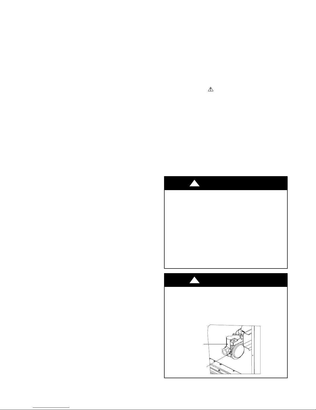
FIRE, EXPLOSION HAZARD
Failure to follow this warning could result in personal
injury or death.
Disconnect gas piping from unit when leak testing at
pressure greater than 0.5 psig (3450 Pa). Pressures
greater than 0.5 psig (3450 Pa) will cause gas valve
damage resulting in hazardous condition. If gas valve is
subjected to pressure greater than 0.5 psig (3450 Pa), it
must be replaced before use. When pressure testing
field--supplied gas piping at pressures of 0.5 psig
(3450 Pa) or less, a unit connected to such piping must
be isolated by closing the manual gas valve.
FIRE HAZARD
Failure to follow this warning could result in personal
injury, death, and/or property damage.
Inlet pressure tab set screw must be tightened and
NPT pipe plug must be installed to prevent gas leaks.
!
. When you see this symbol on the
WARNING
WARNING
1
/8in.
SAFETY CONSIDERATIONS
Improper installation, adjustment, alteration, service,
maintenance, or use can cause explosion, fire, electrical
shock or other conditions which may cause personal injury
or property damage. Consult a qualified installer, service
agency, or your distributor or branch for information or
assistance. The qualified installer or agency must use
factory--authorized kits or accessories when modifying this
518
GAS VALVE
INLET PRESSURE
TAP SET SCREW
2
Page 3
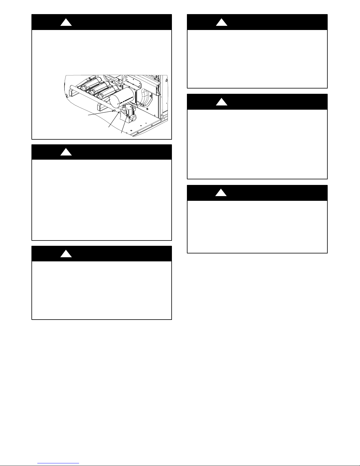
!
WARNING
!
WARNING
FIRE HAZARD
Failure to follow this warning could result in personal
injury, death, and/or property damage.
Manifold pressure tap set screw must be tightened and
1
/8in. NPT pipe plug must be installed to prevent gas
leak.
MANIFOLD PRESSURE
TAP SET SCREW
MANIFOLD
GAS VALVE
!
WARNING
CARBON--MONOXIDE POISONING HAZARD
Failure to follow instructions could result in severe
personal injury or death due to carbon--monoxide
poisoning, if combustion products infiltrate into the
building.
Check that all openings in the outside wall around the
vent (and air intake) pipe(s) are sealed to prevent
infiltration of c om bustion products into the building.
Check that furnace vent (and air intake) terminal(s)
are not obstructed in any way during all seasons.
!
WARNING
UNIT OPERATION AND SAFETY HAZARD
Failure to follow this warning could cause personal
injury, death and/or equipment damage.
Puronr (R--410A) refrige rant systems operate at
higher pressures than standard R--22 systems. Do not
use R--22 service equipment or components on Puron
refrigerant equipment.
!
WARNING
PERSONAL INJURY AND ENVIRONMENTAL
HAZARD
Failure to follow this warning could cause personal
injury or death.
Relieve pre ssure and recover all refrigerant before
system repair or final unit disposal.
Ware safety glasses and gloves when handling
refrigerants. Keep torches and other ignition sources
away from refrigerants and oils.
!
CAUTION
CUT HAZARD
Failure to follow this caution may result in personal
injury.
Sheet metal parts may have sharp edges or burrs. Use
care and wear appropriate protective clothing, safety
glasses and gloves when handling parts and servicing
air conditioning equipment.
ELECTRICAL SHOCK HAZARD
Failure to follow this warning could cause personal
injury or death.
Before performing service or maintenance operations
on unit, always turn off main power switch to unit and
install lock(s) and lockout tag(s). Unit ma y have more
than one power switch.
3
518
Page 4
Rated Indoor Airflow (cfm)
The table to the right lists the rated indoor airflow used
for the AHRI efficiency rating for the units covered in this
document.
Model Number Full Load Airflow (cfm)
48LC**14 4375
48LC**17 4875
48LC**20 5690
48LC**24 6500
48LC**26 7500
Position:
Example:
1234567891011 12 13 14 15 16
48LCD0 24A1A5 -0A0A0
Unit Heat Type
48 - Gas Heat Packaged Rooftop
Model Series - WeatherExpert
®
LC - Ultra High Efficiency
Heat Options
D = Low Gas Heat
E = Medium Gas Heat
F = High Gas Heat
S = Low Heat w/ Stainless Steel Exchanger
R = Medium Heat w/ Stainless Steel Exchanger
T = High Heat w/ Stainless Steel Exchanger
Refrig. Systems Options
0 = Three stage cooling capacity control with TXV
A = Three stage cooling capacity control with TXV
and Humidi-MiZer
®
system
Cooling Tons
14 - 12.5 ton
17 - 15 ton
20 - 17.5 ton
24 - 20 ton
26 - 23 ton
Sens or Options
A = None
B = RA Smoke Detector
C = SA Smoke Detector
D = RA + SA Smoke Detector
E = CO
2
F = RA Smoke Detector and CO
G = SA Smoke Detector and CO
H = RA + SA Smoke Detector and CO
2
2
2
Indoor Fan Motor Options
1 = Standard Static / Vertical Supply, Return Air Flow
2 = Medium Static / Vertical Supply, Return Air Flow
3 = High Static / Vertical Supply, Return Air Flow
4 = Ultra High Static / Vertical Supply, Return Air Flow
5 = Standard Static / Horizontal Supply, Return Air Flow
6 = Medium Static / Horizontal Supply, Return Air Flow
7 = High Static / Horizontal Supply, Return Air Flow
8 = Ultra High Static / Horizontal Supply, Return Air Flow
17
18
Packaging
0 = Standard
1 = LTL
Electrical Options
A = None
B = HACR Circuit Breaker
C = Non-Fused Disconnect
Service Options
0 = None
1 = Unpowered Convenience Outlet
2 = Powered Convenience Outlet
3 = Hinged Panels
4 = Hinged Panels and
Unpowered Convenience Outlet
5 = Hinged Panels and
Powered Convenience Outlet
Intake / Exhaust Options
A = None
B = Temperature Standard Leak Economizer with
Barometric Relief
C = Temperature Standard Leak Economizer with
Centrifugal Power Exhaust - Vertical Only
E = Enthalpy Standard Leak Economizer with
Barometric Relief
F = Enthalpy Standard Leak Economizer with
Centrifugal Power Exhaust - Vertical Only
N = Temperature Ultra Low Leak Economizer with
Barometric Relief
P = Temperature Ultra Low Leak Economizer
with Centrifugal Power Exhaust - Vertical Only
R = Enthalpy Ultra Low Leak Economizer with
Barometric Relief
S = Enthalpy Ultra Low Leak Economizer with
Centrifugal Power Exhaust - Vertical Only
Base Unit Controls
0 = Electro-mechanical Controls
1 = RTU Open Multi-Protocol Controller
4 = SystemVu™ Controller
Design Revision
- = Factory Design Revision
Coil Options: Fin/Tube (Condenser- Evaporator - Hail Guard)
A = Al/Cu - Al/Cu
B = Precoat Al/Cu - Al/Cu
C = E-coat Al/Cu - Al/Cu
D = E-coat Al/Cu - E-coat Al/Cu
E = Cu/Cu - Al/Cu
F = Cu/Cu - Cu/Cu
M = Al/Cu -Al/Cu — Louvered Hail Guard
N = Precoat Al/Cu - Al/Cu — Louvered Hail Guard
P = E-coat Al/Cu - Al/Cu — Louvered Hail Guard
Q = E-coat Al/Cu - E-coat Al/Cu — Louvered Hail Guard
R = Cu/Cu - Al/Cu — Louvered Hail Guard
S = Cu/Cu - Cu/Cu — Louvered Hail Guard
Fig. 1 -- 48LC 14--26 Model Number Nomenclature (Example)
Voltage
1 = 575/3/60
5 = 208-230/3/60
6 = 460/3/60
a48--- 9335
4
Page 5
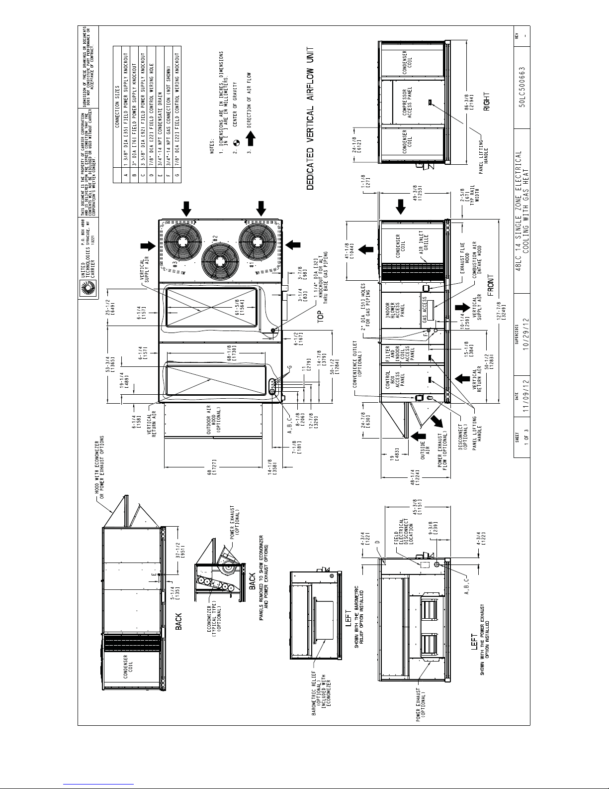
Fig. 2 -- Unit Dimensional Drawing – 14 Size Unit, Sheet 1 of 3
C13057
5
Page 6
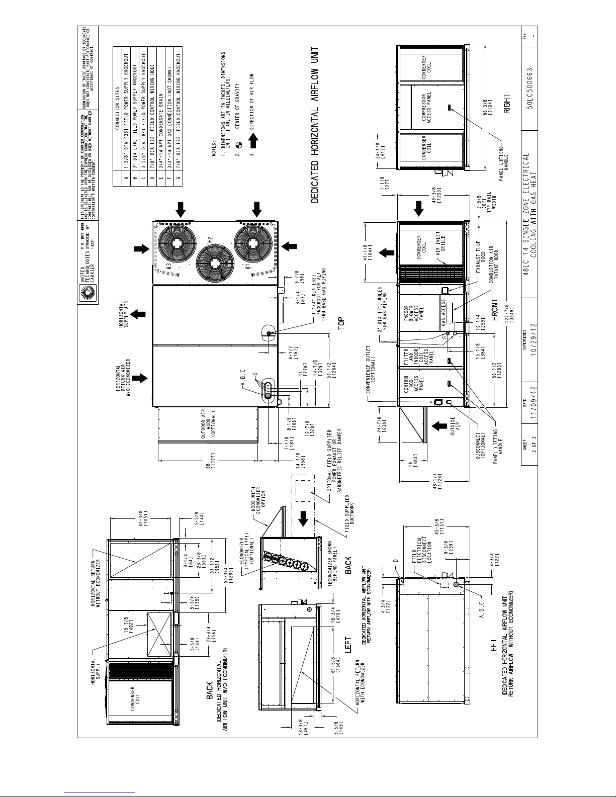
Fig.2(cont)--UnitDimensionalDrawing–14SizeUnit,Sheet2of3
C13058
6
Page 7
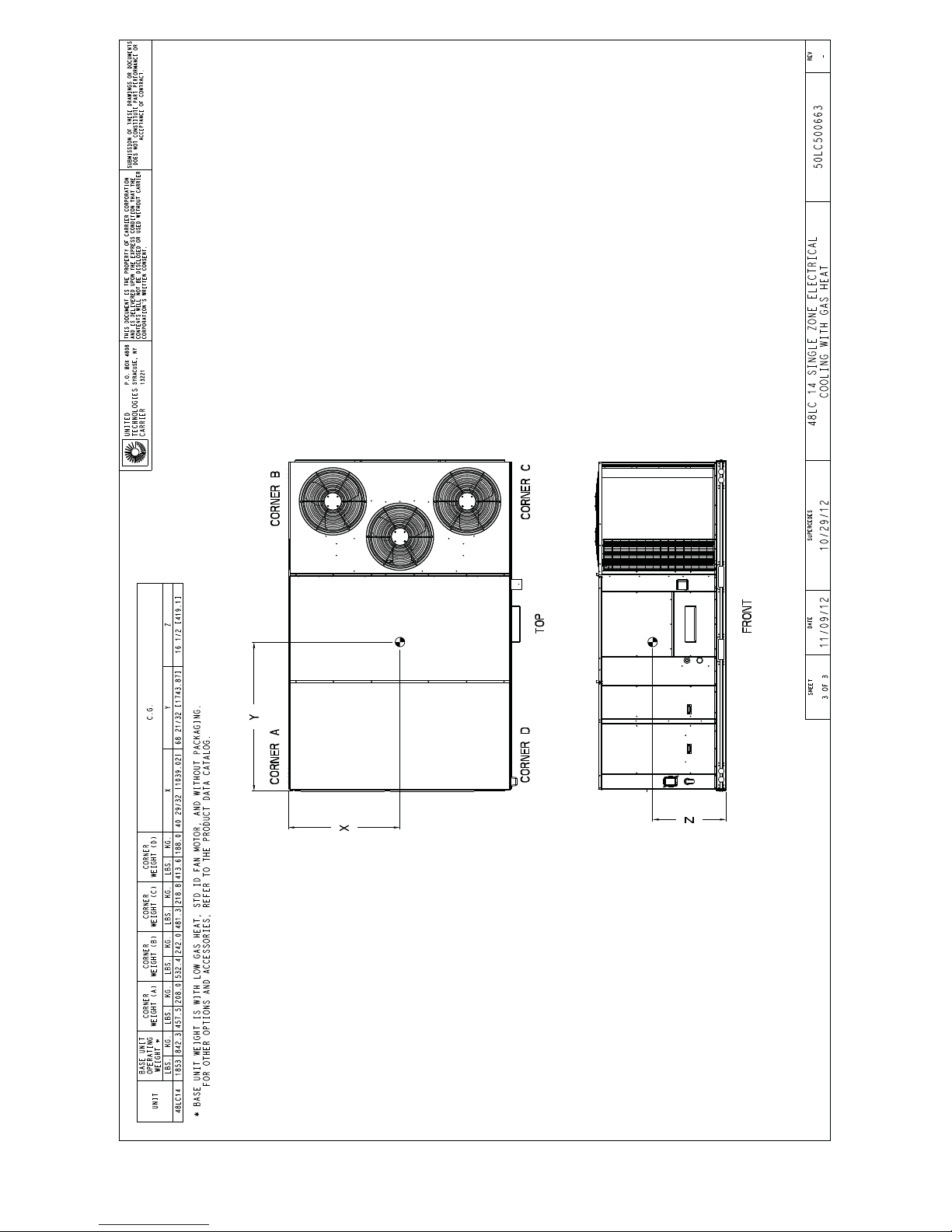
Fig.2(cont)--UnitDimensionalDrawing–14SizeUnit,Sheet3of3
C13059
7
Page 8
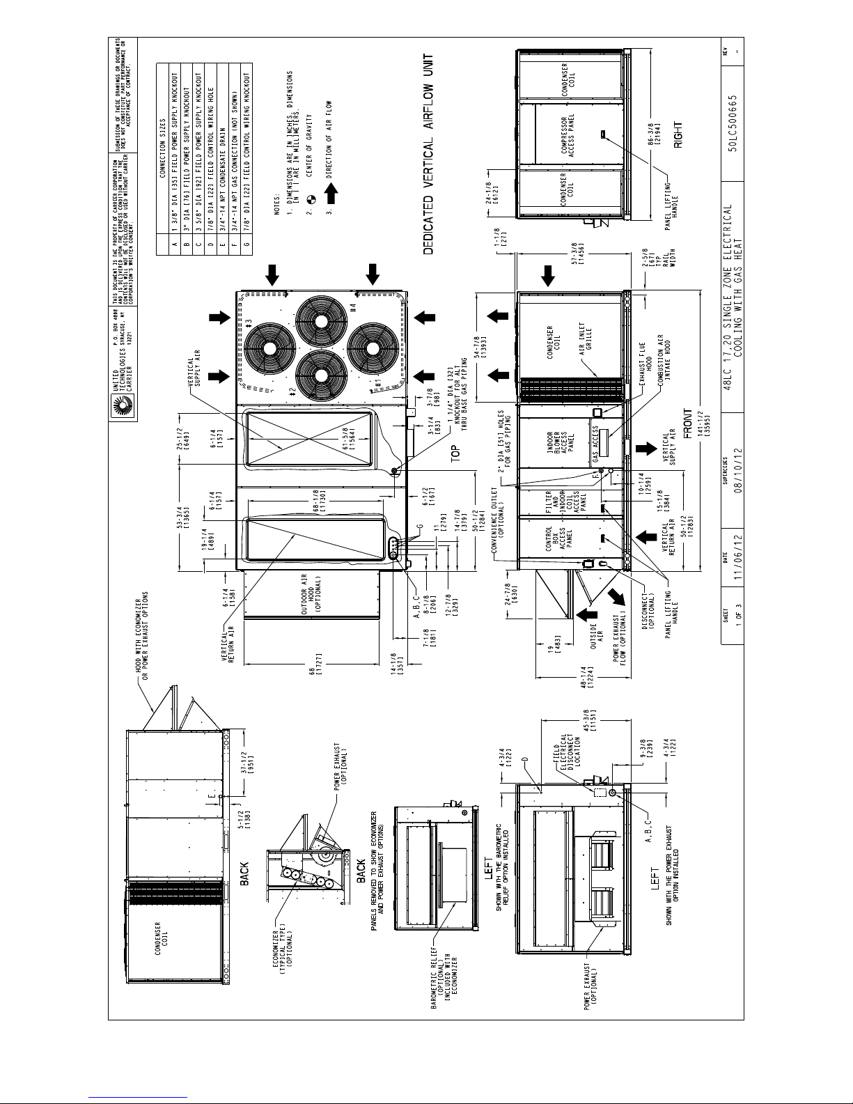
Fig. 3 -- Unit Dimensional Drawing – 17 and 20 Size Units, Sheet 1 of 3
C13032
8
Page 9
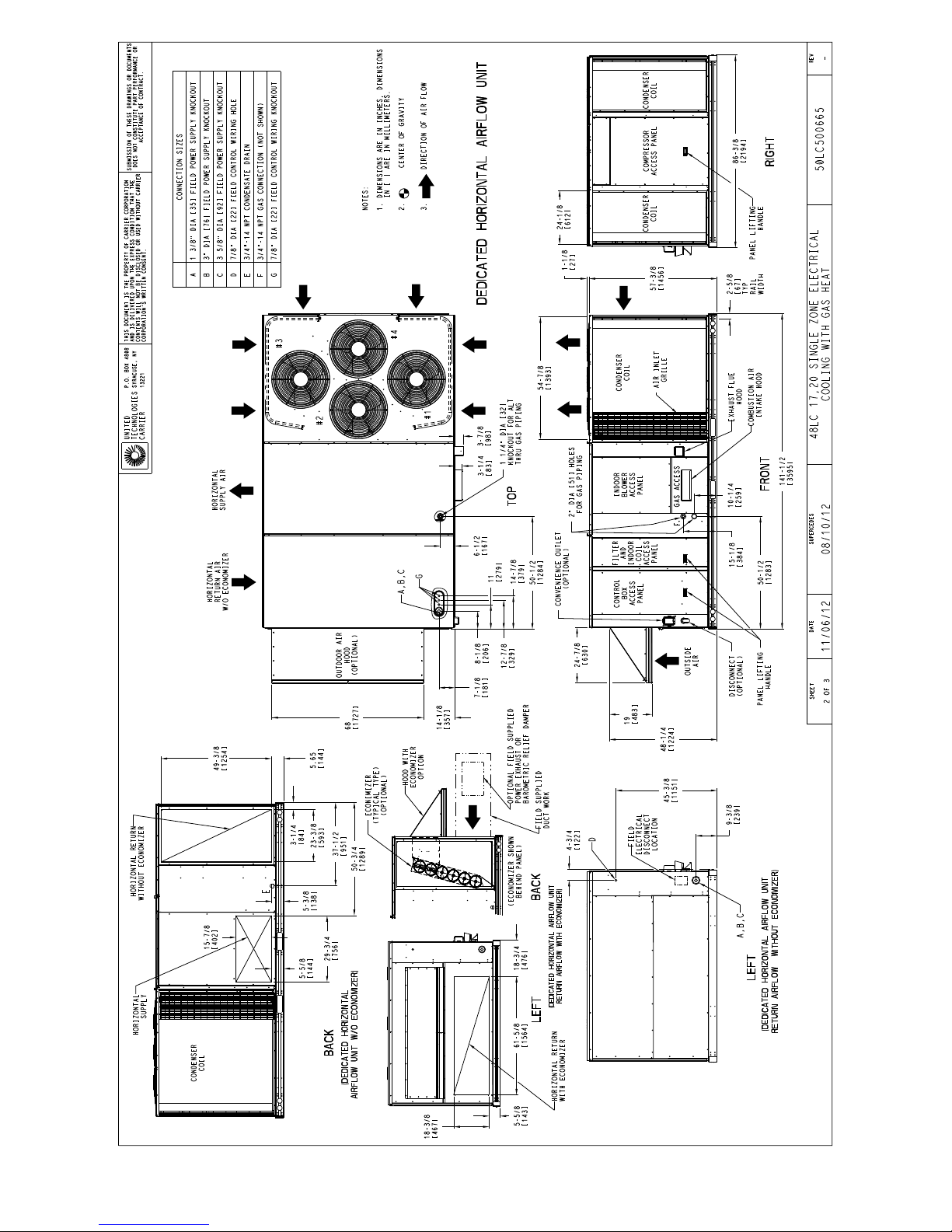
Fig. 3 (cont) -- Unit Dimensional Drawing – 17 and 20 Size Units, Sheet 2 of 3
C13033
9
Page 10
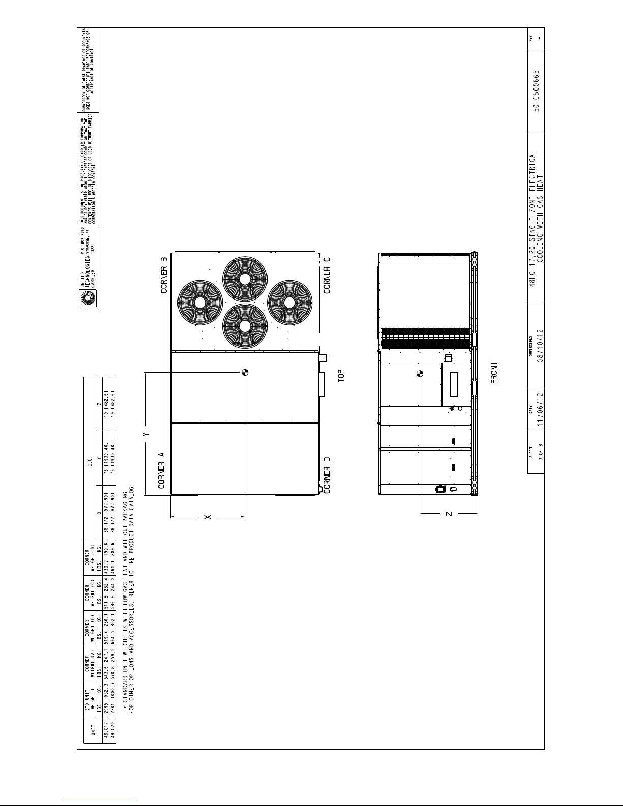
Fig. 3 (cont) -- Unit Dimensional Drawing – 17 and 20 Size Units, Sheet 3 of 3
C13034
10
Page 11
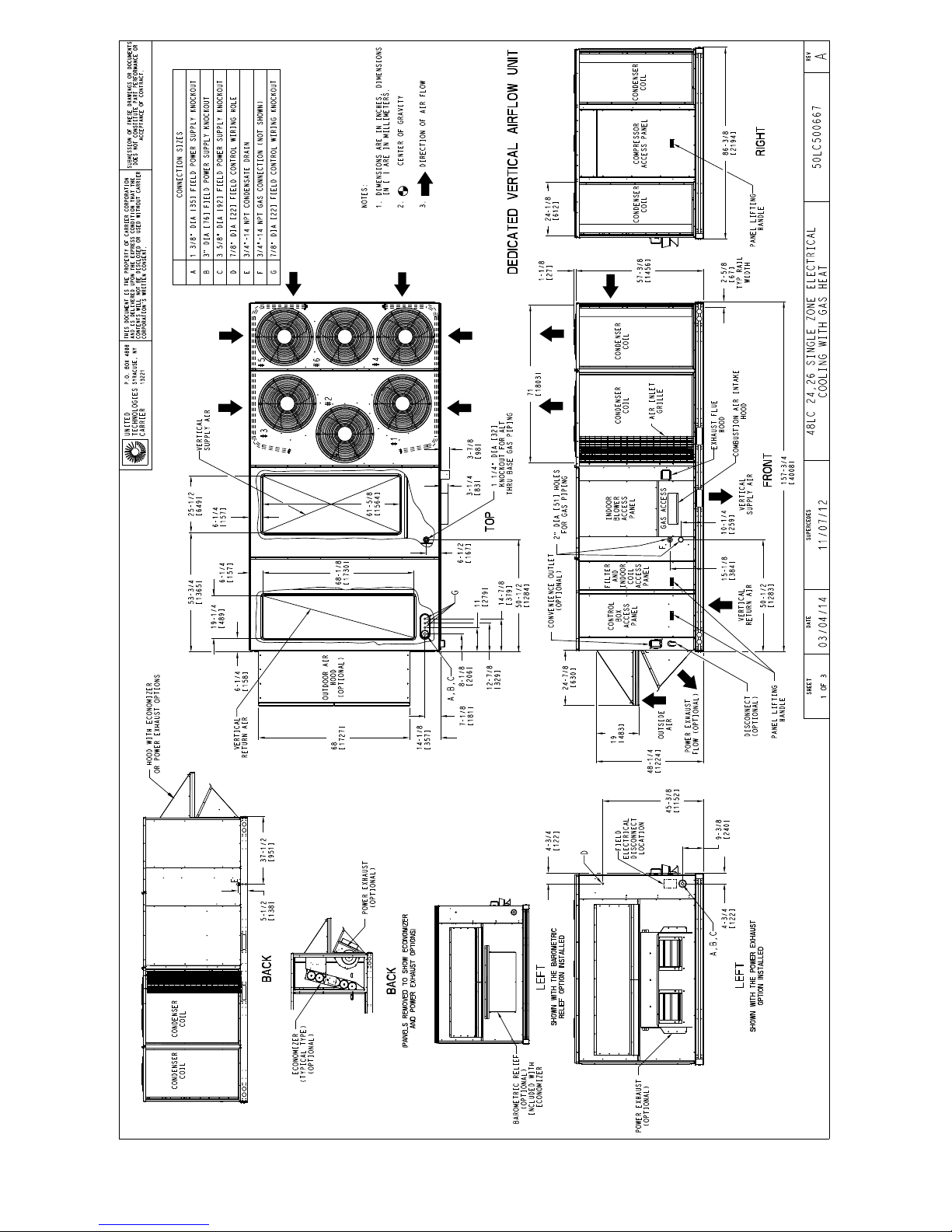
Fig. 4 -- Unit Dimensional Drawing – 24 and 26 Size Units, Sheet 1 of 3
C14106
11
Page 12
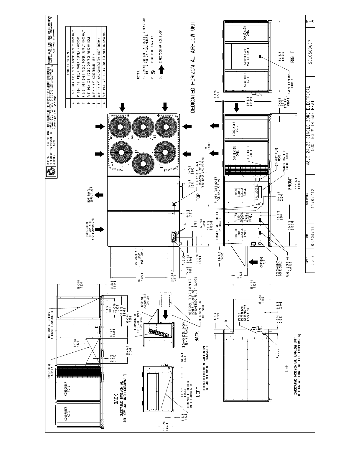
Fig. 4 (cont) -- Unit Dimensional Drawing – 24 and 26 Size Units, Sheet 2 of 3
C14107
12
Page 13
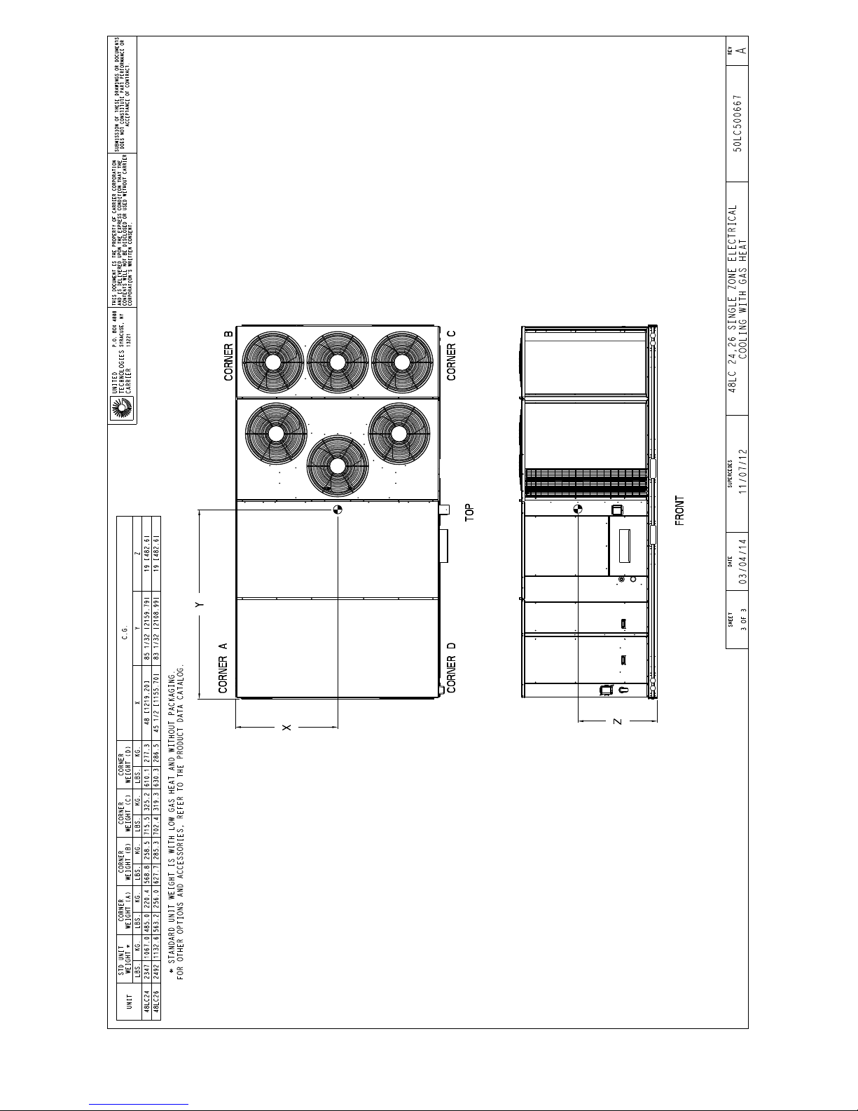
Fig. 4 (cont) -- Unit Dimensional Drawing – 24 and 26 Size Units, Sheet 3 of 3
C14108
13
Page 14
C
D
B
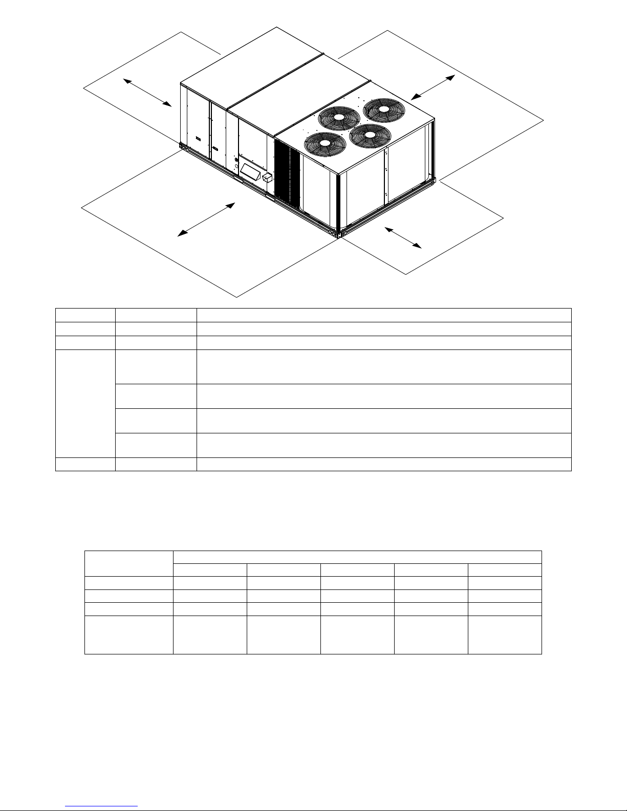
LOCATION DIMENSION CONDITION
A 36-- -in (914 mm) • Recommended clearance for air flow and service
B 42--- in (1067 mm) • Recommended clearance for air flow and service
• No Convenience Outlet
18-- -in (457 mm)
36-- -in (914 mm)
C
42-- -in (1067 mm)
96-- -in (2438 mm)
D 42--- in (1067 mm) • Recommended clearance for service.
NOTE: Unit not designed to have overhead obstruction. Contact Application Engineering for guidance on any application planning
overhead obstruction or for vertical clearances.
•NoEconomizer
• No field--- installed disconnect on economizer hood side (Factory --- installed disconnect installed).
• Convenience Outlet installed.
• Vertical surface behind servicer is electrically non ---conductive (e.g.: wood, fiberglass).
• Convenience Outlet installed.
• Vertical surface behind servicer is electrically conductive (e.g.: metal, masonry).
• Economizer and/or Power Exhaust installed.
• Check for sources of flue products with 10 feet (3 meters) of economizer fresh air intake.
A
Fig. 5 -- Service Clearance Dimensional Drawing
C12384
48LC**
Base Unit 1853 (842.3) 2095 (952.3) 2201 (1000.7) 2347 (1067.0) 2492 (1132.6)
Economizer 246 (112) 246 (112) 246 (112) 246 (112) 246 (112)
Powered Outlet 35 (16) 35 (16) 35 (16) 35 (16) 35 (16)
Curb
14--- in/356 mm 240 (109) 240 (109) 255 (116) 255 (116) 273 (124)
24--- in/610 mm 340 (154) 340 (154) 355 (161) 355 (161) 355 (161)
14 17 20 24 26
Table 1 – Operating Weights
UNIT LB (KG)
14
Page 15

INSTALLATION
Jobsite Survey
Complete the following checks before installation.
1. Consult local building codes and the NEC (National
Electrical Code) ANSI/NFPA 70 for special installation requirements.
2. Determine unit location (from project plans) or select
unit location.
3. Check for possible overhead obstructions which may
interfere with unit lifting or rigging.
Step 1 — Plan for Unit Location
Select a location for the unit and its support system (curb or
other) that provides for the minimum clearances required for
safety. This includes the clearance to combustible surfaces,
unit performance and service access below, around and
above unit as specified in unit drawings. See Fig. 5.
NOTE: Consider also the effect of adjacent units.
Be sure that the unit is installed such that snow will not
block the combustion air intake or flute outlet.
Unit may be installed directly on wood floo rin g or on Class
A, B, or C roof--covering material when roof curb is used.
Do not install unit in an indoor location. Do not locate air
inlets near exhaust vents or other sources of contaminated
air. For proper unit operation, adequate combustion and
ventilation air must be pro vid ed in accord an ce with S ection
5.3 (Air for Combustion and Ventilation) of the National
Fuel Gas Code, ANSI Z223.1 (American National Standards
Institute) and NFPA (National Fire Protection Association)
54 TIA----54----84----1. In Canada, installation must be in
accordance with the CAN1----B149 installation codes for gas
burning appliances.
Although unit is weatherproof, avoid locations that permit
water from higher level runoff and overhangs to fall onto the
unit.
Locate mechanical draft system flue assembly at least 4 ft
(1.2 m) from any opening through which combustion
products could enter the building, and at least 4 ft (1.2 m)
from any adjacent building (or per local code). Locate the
flue assembly at least 10 ft (3.05 m) from an adjacent
unit’s fresh air intake hood if within 3 ft (0.91 m) of same
elevation (or per local code). When unit is located
adjacent t o public walkways, flue assembly must be at
least 7 ft (2.1 m) above grade.
Select a unit mounting system that provides adequate
height to allow installation of condensate trap per
requirements. Refer to Step 11 — Install External
Condensate Trap and Line for required trap dimensions.
Roof Mount —
Check building codes for weight distribution
requirements. Unit operating weight i s shown in Table 1.
Step 2 — Plan for Sequence of Unit Installation
The support method used for this unit will dictate different
sequences for the steps of unit installation. For example, on
curb--mounted units, some accessories must be installed on
the unit before the unit is placed on the curb. Review the
following for recommended sequences for installation steps.
Curb--mounted installation —
Install curb
Install field--fabricated ductwork inside curb
Install thru-- base service connection fittings (affects
curb and unit)
Rig and place unit
Remove top skid
Install outside air hood
Install smoke detector tube
Install combustion air hood
Install flue hood
Install gas piping
Install condensate line trap and piping
Make electrical connections
Install other accessories
Pad--mounted installation —
Prepare pad and unit supports
Rig and place unit
Remove duct covers and top skid
Install smoke detector return air sensor tube
Install field--fabricated ductwork at unit duct openings
Install outside air hood
Install combustion air hood
Install flue hood
Install gas piping
Install condensate line trap and piping
Make electrical connections
Install other accessories
Frame--mounted installation —
Frame--mounted applications generally follow the
sequence for a curb installation. Adapt as required to
suit specific installation plan.
Step 3 — Inspect unit
Inspect unit for transportation damage. File any claim
with transportation agency.
Confirm before i nstallation of unit that voltage, amperage
and circuit protection requirements listed on unit data
plate agree with power supply provided.
On units with hinged panel option, check to be sure all
latches are tight and in closed position.
Locate the carton containing the outside air hood parts; see
Fig. 7 and 13. Do not remove carton until unit has been
rigged and located in final position.
15
Page 16
Step 4 — Provide Unit Support
A
Roof Curb Mount —
Accessory roof curb details and dimensions are shown in
Fig. 8, 9 and 10. Assemble and install accessory roof curb in
accordance with instructions shipped with the curb.
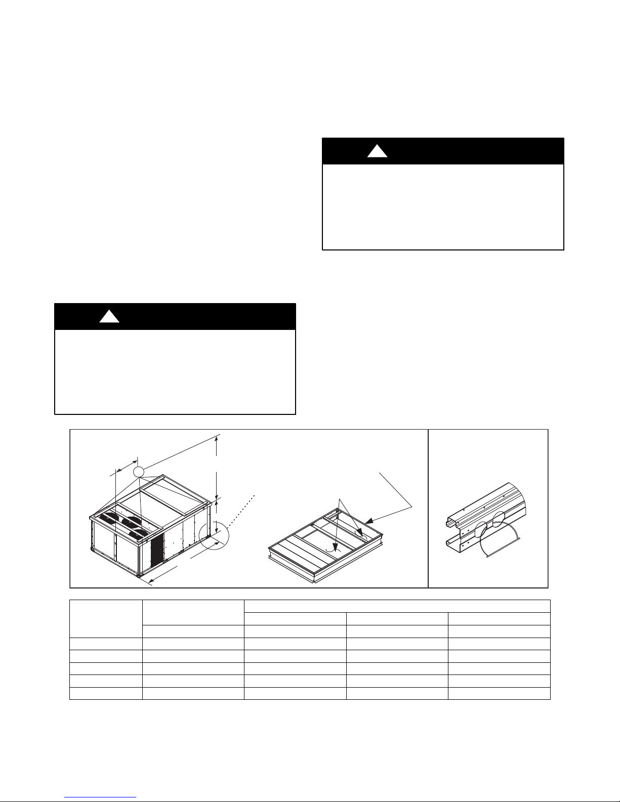
NOTE: The gasketing of the unit to the roof curb is critical
for a watertight seal. Install gasket supplied with the roof
curb as shown in Fig. 8, 9 and 10. Improperly applied
gasket can also result in air leaks and poor unit performance.
Curb should be level. This is necessary for unit drain to
function properly. Unit leveling tolerances are shown in
Fig. 6. Refer to Accessory Roof Curb Installation
Instructions for additional information as required.
C
A
B
Fig. 6 -- Unit Leveling Tolerances
Install insulation, cant strips, roofing fe lt, and counter
flashing as shown. Ductwork must be attached to curb and
not to the unit. Thru--the--base power connection must be
installed before the unit is set on the roof curb. If
field--i nstalled thru--the--roof curb gas connections are
desired, remove knockout in basepan located in the gas
section; see Fig. 7 for location. Gas connections and
power connections to the unit must be field--installed after
the unit is installed on the roof curb.
MAXIMUM ALLOWABLE
DIFFERENCE IN. (MM)
A-B
0.25” (6)
B-C
0.5” (12)
A-C
0.5” (12)
C10628
box area of access panel; see Fig. 2, 3, or 4 for basepan
knockout loc ations for location. Attach the service
connections to the basepan.
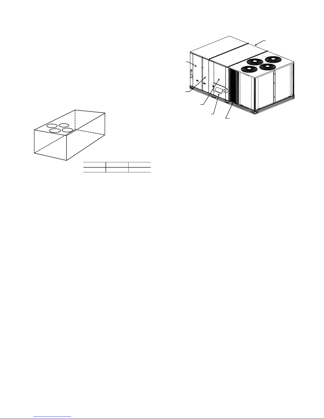
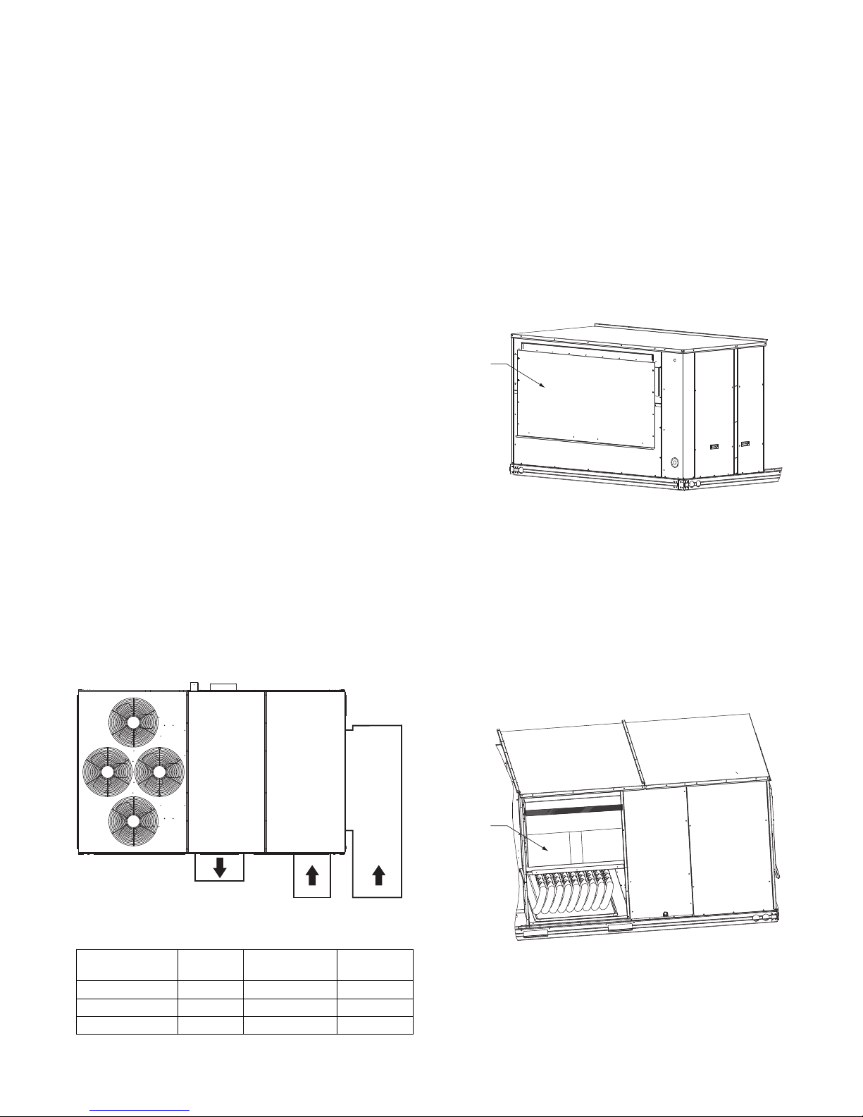
Hood Carton Location
(rear access panel)
Control Box
ccess Panel
Filter and
Indoor Coil
Access Panel
Indoor Blower
Access Panel
Gas Heat
Access Panel
Compressor
(each side)
C11154
Fig. 7 -- Typical Access Panel and Compr es s o r Locations
Slab Mount (Horizontal Units Only) —
Provide a level concrete slab that extends a minimum of
6–in. (150 mm) beyond unit cabinet. Install a gravel apron
in front of condenser c oil air inlet to prevent grass and
foliage from obstructing airflow.
NOTE: Horizontal units may be installed on a roof curb
if required.
Alternate Unit Support (In Lieu of Curb or Slab
Mount) —
A non--combustible sleeper rail can be used in the unit
curb support area. If sleeper rails cannot be used, support
the long sides of the unit with a minimum of 4 equally
spaced 4--in. x 4--in. (102 mm x 102 mm) pads on each
side. Locate pads so that they support the rail s. Make sure
to avoid the fork openings.
If electric and control wiring is to be routed through the
basepan, remove knockouts in basepan located in control
16
Page 17

C13054
Fig. 8 -- Roof Curb Details – 14 Size Unit
17
Page 18
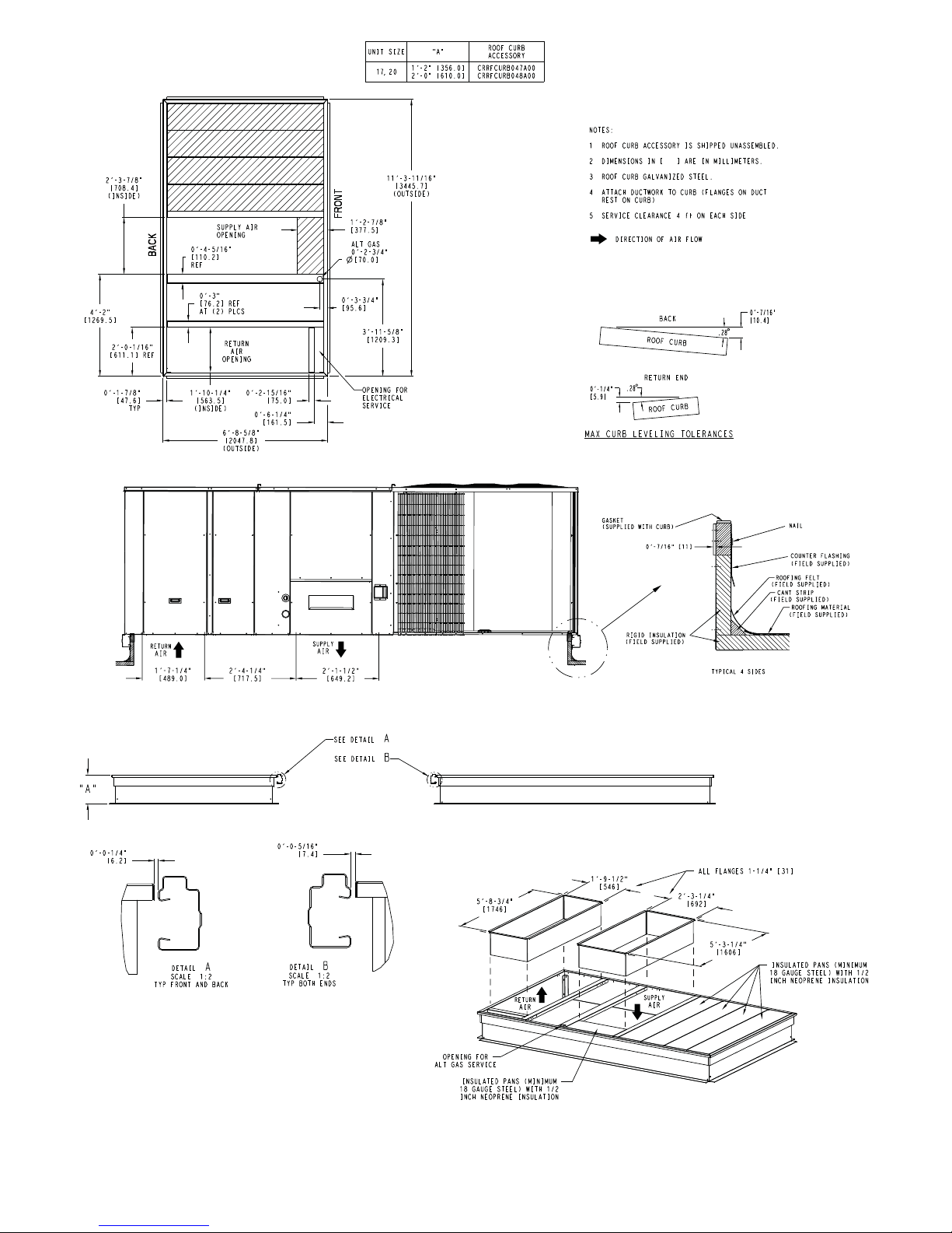
Fig. 9 -- Roof Curb Details – 17 and 20 Size Units
C13055
18
Page 19
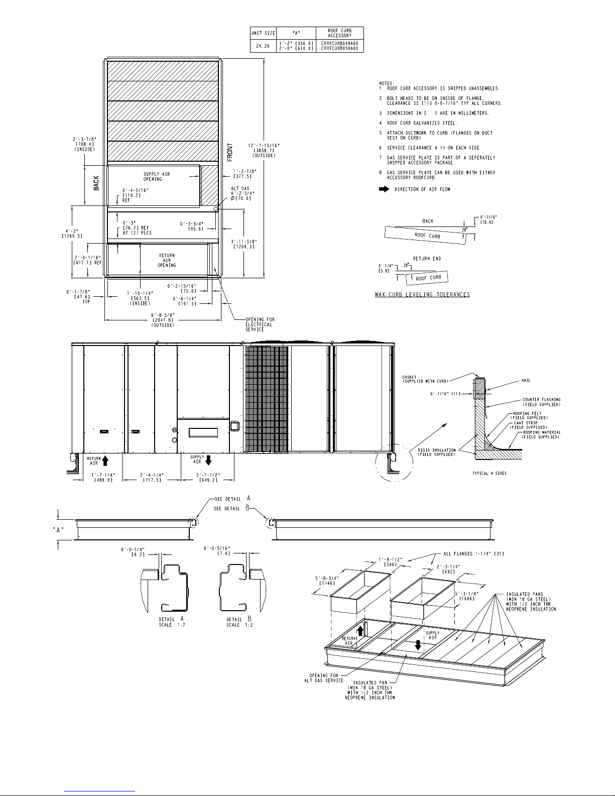
Fig. 10 -- Roof Curb Details – 24 and 26 Size Units
C13056
19
Page 20
Step 5 — Field Fabricate Ductwork
Cabinet return-air static pressure (a negative condition)
shall not exceed 0.5 in. wg (87 Pa) with economizer or
without economizer.
For vertical ducted applications, secure all ducts to roof curb
and building structure. Do not connect ductwork to unit.
Fabricate supply ductwork so that the cross sectional
dimensions are equal to or greater than the unit supply
duct opening dimensions for the first 18 in. (458 mm) of
duct length from the unit basepan.
Step 6 — Rig and Place Unit
Keep unit upright and do not drop. Spreader bars are not
required if top crating is left on unit. Rollers may be used
to move unit across a roof. Level by using unit frame as a
reference. See Table 1 (on page 14) and Fig. 11 (below)
for additional information.
Lifting holes are provided in base rails as shown in
Fig. 11. Refe r to riggi ng instructions on unit .
!
CAUTION
Insulate and weatherproof all external ductwork, joints,
and roof openings with counter flashing and mastic in
accordance with applicable codes.
Ducts passing through unconditioned spaces must be
insulated and covered with a vapor barrier.
If a plenum return is used on a vertical unit, the return
should be ducted through the roof deck to comply with
applicable fire codes.
A minimum clearance is not required around ductwork.
!
CAUTION
PROPERTY DAMAGE HAZARD
Failure to follow this caution may result in damage
to roofing materials.
Membrane roofs can be cut by sharp sheet metal
edges. Be careful when placing any sheet metal parts
on such roof.
"914-1371"
(36"-54")
"B"
SEE DETAIL A
UNIT DAMAGE HAZARD
Failure to follow this caution may result in
equipment damage.
All panels must be in place when rigging. Unit is not
designed for handling by fork truck when packaging
is removed.
Before setting the unit onto the curb, recheck gasketing on
curb.
PLACE ALL SEAL STRIP
IN PLACE BEFORE PLACING
UNIT ON ROOF CURB.
DUCT END
DETAIL A
"A"
UNIT
48LC**14 2135 970 127.8 3249 59.1 1501 52.3 1328
48LC**17 2377 1080 141.5 3595 65.5 1664 60.3 1532
48LC**20 2483 1129 141.5 3595 65.5 1664 60.3 1532
48LC**24 2629 1195 157.8 4007 72.8 1849 60.3 1532
48LC**26 2774 1261 157.8 4007 7208 1849 60.3 1532
NOTES:
1. Dimensions in ( ) are inches.
2. Hook rigging shackles through holes in base rail, as shown in detail “A .” Holes in b ase rails are centered around the unit center of
gravity. Use wooden top to prevent rigging straps from damaging unit.
MAX WEIGHT
LB KG IN MM IN MM IN MM
"C"
C09107
DIMENSIONS
A B C
Fig. 11 -- Rigging Details
20
Page 21
PositioningonCurb—
r
Position unit on roof curb so that the following clearances
are maintained:
curb and the base rail inside the right and left,
1
/4in. (6 mm) clearance between the roof
1
/2in.
(12 mm) clearance between the roof curb and the base rail
inside the front and back. This will result in the distance
between the roof curb and the base rail inside on the
condenser end of the unit being approximat ely equal to
Details A and B in Fig. 8, 9 and 10.
Do not attempt to slide unit on curb after unit is set. Doing
so will result in damage to the roof curb seal.
Although unit is weatherproof, guard against water from
higher level runoff and ove rhangs.
Flue vent dischar ge must have a minimum horizontal
clearance of 48 in. (1220 mm) from electric and gas meters,
gas regulators, and gas relief equipment. Minimum distance
between unit and other electrically live parts is 48 inches
(1220 mm).
Flue gas can deteriorate building materials. Orient unit such
that flue gas will not affect building materials . Locate
mechanical draft system flue assembly at least 48 in.
(1220 mm) from an adjacent building or combustible
material.
Field--supplied(3/4--inch) flanges should be attached to
horizontal duct openings (see Fig. 12) and all ductwork
should be secured to the flanges. Insulate and weatherproof
all external ductwork, joints, and roof or building openings
with counter flashing and mastic in accordance with
applicable codes.
Step 8 — Install Outside Air Hood — Factory
Option
The outside air hood for factory--option economizer is
shipped in knock--down form and requires field assembly.
The panel for the hood top is shipped on the end of the
unit (see Fig. 13). The remaining parts for the hood
assembly (including side panels, filters and tracks) are
shippedinacartonthatissecuredtotherearoftheblower
assembly. Access the carton location through rear panel
(see Fig. 14).
Hood Top
Shipping
Position
After unit is in position, remove rigging skids and
shipping materials.
Step 7 — Horizontal Duct Connection
Refer to Fig. 2, 3 and 4 for locations and sizes of the
horizontal duct connections. Note that there are two different
return air duct connection locations – one for unit without an
economizer (on back side of unit) and a different one for
unit equipped with an economizer (on left end, under the
economizer hood). The supply air duct connection is on the
back side. See Fig. 12 for top view depicting typical
horizontal duct arrangements.
C09134
Fig. 13 -- Hood Top – Shipping Position
To remove the hood parts package:
1. Remove the back blower access panel.
2. Locate and cut the strap, being careful to not damage
any wiring.
3. Carefully lift the hood package carton through the
back blower access opening.
See Fig. 15 for identification of the various parts of the
hood assembly.
Hood
Package
Horizontal
Supply Air
Supply
Location Back Back Left end
H e i g h t --- I n . ( m m ) 157/8(402) 493/8(1253) 183/8(467)
W i d t h --- i n . ( m m ) 293/4(756) 233/8(593) 615/8(1564)
Return Air Duct
Return without
Economizer
Fig. 12 -- Horizontal Duct Opening Dimensions
without
Economizer
Return Air Duct
with Economize
Return with
Economizer
C10626
C09133
Fig. 14 -- Hood Package – Shipping Location
21
Page 22
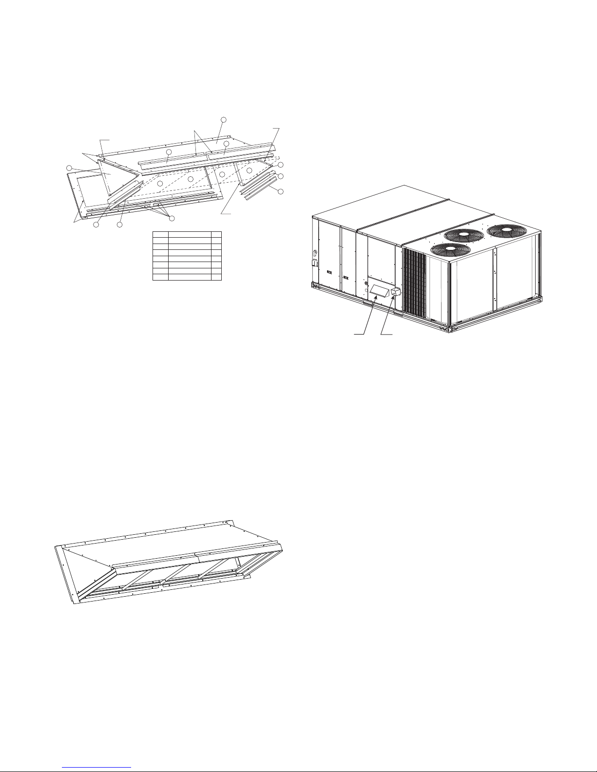
To assemble the outside air hood:
A
1. Remove hood top panel from shipping position on
unit end.
2. Install four angles to the upper end panel using the
screws provided.
3. Apply seal strip to mating flanges on the side plates
of the hood (see Fig. 15).
pply Seal Strips
to the back of
these flanges
2
Seal Strips
5
Apply Seal Strip
to the front of
this flange
6
Apply Seal Strips
to the back of
these surfaces
7
4
Item # Description Qty
1 Angles 4
2 Side Plates 2
3 Hood 1
4 Outdoor Air Screens 4
5 Side Filter Supports 2
6 Side Drip Angles 2
7 Top Diverters 2
4
1
3
7
4
Apply Seal Strip
to the back of
this flange
Apply Seal Strip
to the front of
this flange
4
C09079
Fig. 15 -- Hood Part Identification and Seal Strip
Application Areas
Step 9 — Install Flue Hood and Combustion Air
Hood
The flue hood is shipped screwed to the fan deck inside
the burner compartment. Remove the burner access panel
and then rem ove the flue hood from i ts shipping location.
Using the screws provided, install flue hood in the
location shown in Fig. 17.
The combustion air hood is attache d to the back of the
burner access panel. Remove the two screws securing the
hood to the back of the burner access panel. Using the two
2
5
6
screws, re--attach the hood to the front of the burner
access panel as shown in Fig. 17.
4. Secure side plates to panel using the screws provided.
5. Apply seal strip to mating flange of the hood (see
Fig. 15).
Combustion
Air Hood
Flue Hood
C10744
Fig. 17 -- Flue Hood and Combustion Air Hood Details
6. Secure top flange using screws provided in kit.
7. Install outdoor air screens by sliding them into the
channel formed by the four angles install ed in step 2.
Make sure that the screens extend across the entire
length of the hood.
8. Install side filter supports using the screws provided.
9. Install side drip angles using the screws provided.
10. Run a continuous length of seal strip across the hood
covering the engagement holes in the lower hood.
11. Install top diverter using the screws provided.
12. On units with barometric relief, remove screws at bottom of relief damper. Do not discard damper door.
C09090
Fig. 16 -- Hood Assembly – Completed
22
Page 23
Step 10 — Install Gas Piping
Installation of the gas piping must be in accordance with
local building codes and with applicable national codes.
In U.S.A., refer to NFPA 54/ANSI Z223.1 National Fuel
Gas Code (NFGC). In Canada, installation must be
accordance with the CAN/CSA B149.1 a nd CAN/CSA
B149.2 installation codes for gas burning appliances.
This unit is factory equipped for use with Natural Gas fuel
at elevations up to 2000 ft (610 m) above sea level. Unit
may be field converted for operation at elevations above
2000 ft (610 m) and/or for use with liquefied petroleum
fuel. See accessory kit installation instructions regarding
these accessories.
NOTE: Furnace gas input rate on rating plate is for
installation up to 2000 ft (610 m) above sea level. In
U.S.A. the input rating for altitudes above 2000 ft (610 m)
must be derated by 4% for each 1000 ft (305 m) above sea
level.
For natural gas applications, gas pressure at unit gas
connection must not be less than 5 in. wg (1246 Pa) or
greater than 13 in. wg (3240 Pa) while the unit is
operating. For liquified petroleum applications, the gas
pressure must not be less than 11 in. wg (2740 Pa) or
greater than 13 in. wg (3240 Pa) at the unit connection.
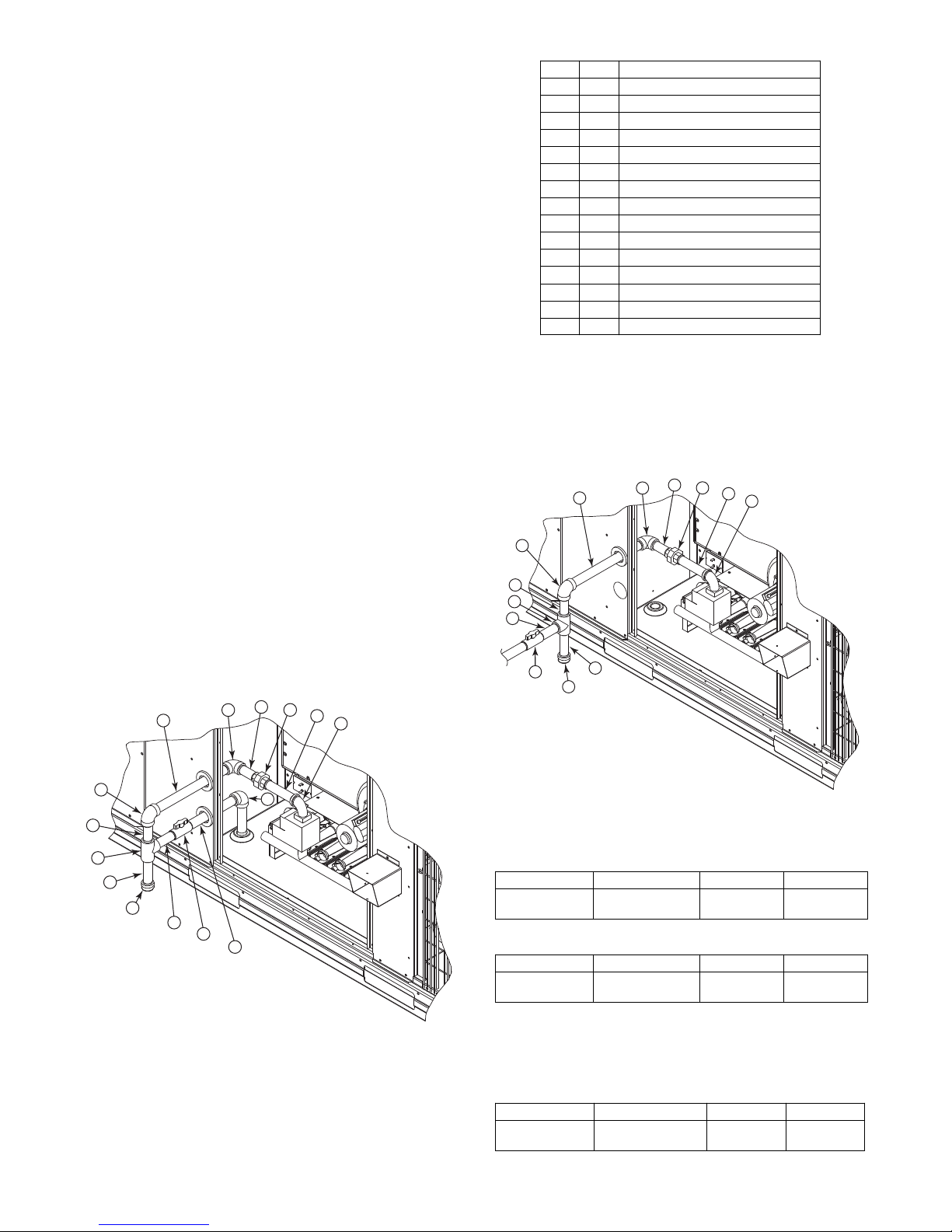
T able 2 – Typical
Item Qty Description
1 1 90 Deg Street Elbow
2 1 5 Inch Long Nipple
3 1 Ground--- Joint Union
4 1 3 Inch Long Nipple
5 1 90 Deg Elbow
6 1 12 Inch Long Nipple
7 1 90 Deg Elbow
8 1 3 Inch Long Nipple
9 1 TEE
10 1 4 Inch Long Nipple (Sediment Trap)
11 1 Cap
12 1 31/2Inch Long Nipple
13 1 NIBCO* Ball Valve (GB30)
14 1 8 Inch Long Nipple
15 1 90 D eg Elbow
3
/4--in. NPT Field Supplied Piping Parts
Pipe gas supply into 90 degree elbow item 15 (see Table 2)
through the hole in the unit basepan.
For typical3/4inch NPT field supplied fittings required
for NON Thru--Base gas supply starting from the unit gas
valve, omit items 14 and 15 from Table 2 and pipe gas
supply into TEE. See Fig. 19.
4
6
5
3
2
1
Gas Supply Line —
The gas supply pipe enters the unit adjacent to the burner
access panel on the front side of the unit, through the
grommeted hole. The gas connection to the unit is made
3
to the
Table 2 lists typical
/4in. FPT gas inlet port on the unit ga s valve.
3
/4inch NPT (National Pipe Thread)
field supplied pipe fittings required for Thru--Base gas
supply, starting from the unit gas valve (see Fig. 18).
4
6
7
8
9
10
11
12
5
13
14
3
2
1
15
7
8
9
12
13
10
11
C101006
Fig. 19 -- Gas Supply Line Piping
Table 3 – Natural Gas Supply Line Pressure Ranges
UNIT MODEL UNIT SIZE MIN MAX
48LC** 14, 17, 20, 24, 26
5.0 in. wg
(1246 Pa)
13.0 in. wg
(3240 Pa)
Table 4 – Liquid Propane Supply Line Pressure Ranges
UNIT MODEL UNIT SIZE MIN MAX
48LC** 14, 17, 20, 24, 26
11.0 in. wg
(2740 Pa)
13.0 in. wg
(3240 Pa)
Fig. 18 -- Gas Supply Line Piping with Thru--Base
C10999
Manifold pressure is factory--adjusted for natural gas (NG)
fuel use. Adjust as required to obtain best flame
characteristics.
Table 5 – Natural Gas Manifold Pressure Ranges
UNIT MODEL UNIT SIZE HIGH FIRE LOW FIRE
48LC** 14, 17, 20, 24, 26
* NIBCO is a registered trademark of NIBCO Inc.
23
3.0 in. wg
(747 Pa)
2.0 in. Wg
(498 Pa)
Page 24
Manifold pressure for liquid propane (LP) fuel must be
R
adjusted to specified range. Follow instructions in the
accessory kit to make initial readjustment.
Table 6 – Liquid Propane Manifold Pressure Ranges
UNIT MODEL UNIT SIZE HIGH FIRE LOW FIRE
48LC** 14, 17, 20, 24, 26
48LCS* 14 only
!
CAUTION
11.0 in. wg
(2740 Pa)
9.8 in. wg
(2441 Pa)
7.3 in. Wg
(1818 Pa)
6.5 in. Wg
(1619 Pa)
EQUIPMENT DAMAGE HAZARD
Failure to follow this caution may result in damage
to equipment.
When connecting the gas li ne to the unit gas valve,
the installer MUST use a backup wrench to prevent
damage to the valve.
Install a gas supply line that runs to the unit heating
section. Refer to the NFPA 54/NFGC or equivalent code
for gas pipe sizing data. Do not use a pipe smaller than the
size specified. Siz e the gas supply line to allow for a
maximum pressure drop of 0.5--in. wg (124 Pa) between
gas regulator source and unit gas valve connection when
unit is operating at high--fire flow rate.
The gas supply line can approach the unit in two ways:
horizontally from outside the unit (across the roof), or
through unit basepan. Observe clearance to gas line
components per Fig. 20.
X
9” MINIMUM CLEARANCE
BASE UNIT
BASE RAIL
FOR PANEL REMOVAL
MANUAL GAS
SHUTOFF VALVE
48” MINIMUM
ROOF
CURB
NFGC – National Fuel Gas Code
Field supplied.
*
NOTE: Follow all local codes.
STEEL PIPE
NOMINAL DIAMETER
(in.)
1
/
2
3
/
or 1
4
1
1
/
or larger
4
LEGEND
GAS
REGULATOR
*
DRIP LEG
PER NFGC
FABRICATED
SPACINGOFSUPPORTS
X DIMENSION
(ft)
6
8
10
*
*
FIELD-
SUPPORT
FROM
GAS
METE
*
C11121
Fig. 20 -- Gas Piping Guide
Factory--Option Thru--Base Connections —
Electrical Connections: Knockouts are located in the
control box area. Remove the appropriate size knockout
for high voltage connection. Use the field supplied
connector depe nding on wiring or conduit being utilized.
7
Remove the
/8--in. (22mm) knockout and appropriate
connector for low voltage wiring. If non--unit powered
7
convenience outlet is being utilized, remove the
/8-- i n .
(22mm) knockout and utilize appropriate connector for
115 volt line. See “Step 12 — Make Electrical
Connections” for details.
Gas Connections: Remove the knockout in the base pan
3
and route
/4--in. gas line up through the opening. Install an
elbow and route gas line through opening in panel after first
removing plastic bushing. Install a gas shut off followed by a
drip leg and ground--joint union. Route gas line into gas
section through the grommet (Part #: KA56SL112) at the gas
inlet and into the gas valve. See Fig. 18 and Table 2. If a
regulator is installed, it must be located 4 feet (1.22 meters)
from the flue outlet.
Some municipal codes require that the manual shutoff
valve be located upstream of the sediment trap. See
Fig. 19 for typical piping arrangements for gas piping that
has been routed through the sidewall of the base pan.
When installing the gas supply line, observe local codes
pertaining to gas pipe installations. Refer to the NFPA
54/ANSI Z 223. 1 NFGC latest edition (in Canada,
CAN/CSA B149.1). In the absence of local building codes,
adhere to the following pertinent recommendations:
1. Avoid low spots in long runs of pipe. Grade all pipe
1
/4--in. in every 15 ft (7 mm in every 5 m) to prevent
traps. Grade all horizontal runs downward to risers.
Use risers to connect to heating section and to meter.
2. Protect all segments of piping system against physical
and thermal damage. Support all piping with appropriate straps, hangers, etc. Use a minimum of one
hanger every 6 ft (1.8 m). For pipe sizes larger than
1
/2--in., follow recommendations of national codes.
3. Apply joint compound (pipe dope) sparingly and only
to male threads of joint when making pi pe
connections. Use only pipe dope that is resistant to
action of liquefied petroleum gases as specified by
local and/or national codes. If using PTFE (Teflon*)
tape, ensure the material is Double Density type and
is labeled for use on gas lines. Apply tape per
manufacturer’s instructions.
4. Pressure--test all gas piping in accordance with local
and national plumbing and gas codes before connecting piping to unit.
NOTE: Pressure test the gas supply system after the gas
supply piping is connected to the gas valve. The supply
piping must be disconnected from the gas valve during the
testing of the piping systems when test pressure is in
excess of 0.5 psig (3450 Pa). Pressure test the gas supply
piping system at pressures equal to or less than 0.5 psig
(3450 Pa). The unit heating section must be isolated from
the gas piping system by closing the external ma in manual
shutoff valve and slightly opening the ground--joint union.
Check for gas leaks at the field--installed and
factory--installed gas lines after all piping connections
have been completed. Use soap--and--water solution (or
method specified by local codes and/or regulations).
* Teflon is a registered trademark of DuPont.
24
Page 25
!
WARNING
FIRE OR EXPLOSION HAZARD
Failure to follow this warning could result in personal
injury, death and/or property damage.
S Connect gas pipe to unit using a backup wrench to
avoid damaging gas controls.
S Never purge a gas line into a combustion chamber.
S Never test for gas leaks with an open flame. Use a
commercially available soap solution made
specifically for the detection of leaks to check all
connections.
S Use proper length of pipe to avoid stress on gas
control manifold.
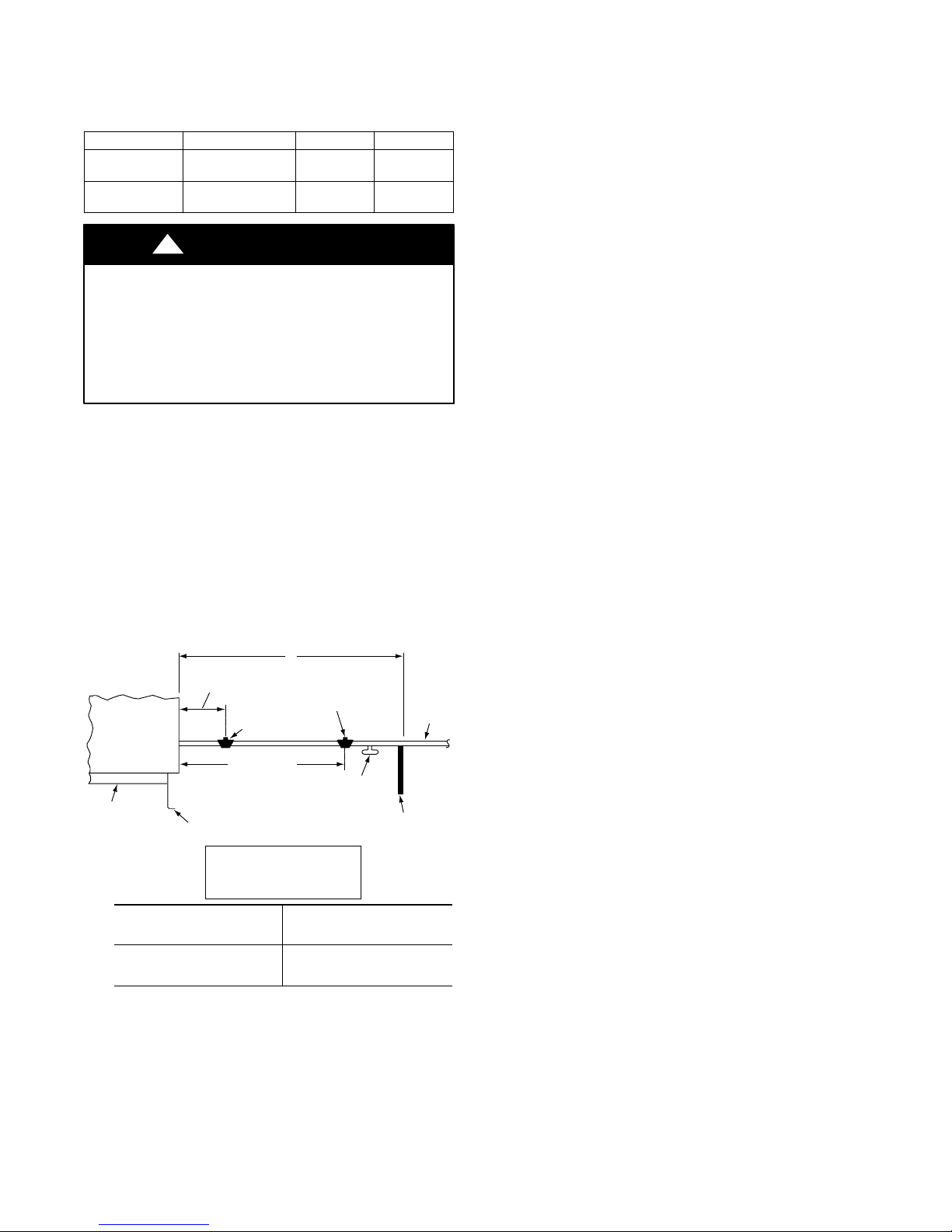
The piping for the condensate drain and external trap can
be completed after the unit is in place. Hand tighten
fittings to the drain pan fitting. Provide adequate support
for the drain line. Failure to do so can result in damage to
the drain pan. See Fig. 23.
MINIMUM PITCH
1” (25mm) PER
10’ (3m) OF LINE
TO ROOF
DRAIN
BASE RAIL
OPEN
VENT
3˝ (76mm)
MIN
SEE NOTE
NOTE: If orifice hole appears damaged or it is suspected to
have been redrilled, check orifice hole with a numbered drill
bit of correct size. Never redrill an orif ice. A bur r--free and
squarely aligned orifice hole is essential for proper flame
characteristics.
BURNER
ORIFICE
A93059
Fig. 21 -- Orifice Hole
Step 11 — Install External Condensate Tr ap and
Line
The unit has one3/4-in. condensate drain connection on the
end of the condensate pan (see Fig. 22). See Fig. 2, 3 and 4,
item “E”, in the view labeled “BACK (HORIZONTAL
DISCH A RG E) ” (located on sh eet 2 of 3 of each figure) for
the location of the condensate drain connection.
ROOF
DRAIN PLUG
NOTE: Trap should be deep enough to offset maximum unit static
difference. A 4” (102mm) trap is recommended.
CURB
C11291
Fig. 23 -- Condensate Drain Piping Details
All units must have an external trap for condensate
drainage. Install a trap at least 4-in. (102 mm) dee p and
protect against freeze-up. If drain line is installed
downstream from the external trap, pitch the line away
from the unit at 1-in. per 10 ft (25 mm in 3 m) of run. Do
not use a pipe size smaller than the unit connection
3
/4-in.).
(
Step 12 — Make Electrical Connections
!
WARNING
ELECTRICAL SHOCK HAZARD
Failure to follow this warning could result in personal
injury or death.
Do not use gas piping as an electrical ground. Unit
cabinet must have an uninterrupted, unbroken electrical
ground to minimize the possibility of personal injury if
an electrical fault should occur. This ground may consist
of electrical wire connected to unit ground lug in control
compartment, or conduit approved for electrical ground
when installed in accordance with NEC (National
Electrical Code); ANSI/NFPA 70, latest edition (in
Canada, Canadian Electrical Code CSA [Canadian
Standards Association] C22.1), and local electrical
codes.
CONDENSATE
DRAIN
CONNECTION
Fig. 22 -- Condensate Drain Pan Connection
C10729
NOTE: Field--supplied wiring shall conform with the
limitations of minimum 63_F(33_C) rise.
Field Power Supply —
If equipped with optional Powered Convenience Outlet:
The power source leads to the convenience outlet’s
transformer primary are not factory connected. Installer
must connect these leads according to required operation
of the convenience out let. If an always--energized
convenience outlet operation is desire d, connect the
source leads to the line side of the uni t--mounted
25
Page 26
disconnect. (Check with local codes to ensure this method
is acceptable in your area.) If a de--energize via unit
disconnect switch operation of the convenienc e outlet is
desired, connect the source leads to the load side of the
unit disconnect. On a unit without a unit--mounted
disconnect or HACR, connect the source leads to the
terminal block with unit field power leads. See Fig. 24.
BLK
YEL
BLU
LOAD
SIDE
LINE
SIDE
SEE
DETAIL
A
L1
L2
L3
A
DETAIL
CONTROL BOX
C11181
Fig. 24 -- Location of TB1
Field power wires are connected to the unit at line--side
pressure lugs on the terminal block (see wiring diagram
label for control box component arrangement) or at
factory--installed option non--fused disconnect switch or
HACR breaker. Use copper conductors only.
NOTE: Make field power connections directly to line
connection pressure lugs only.
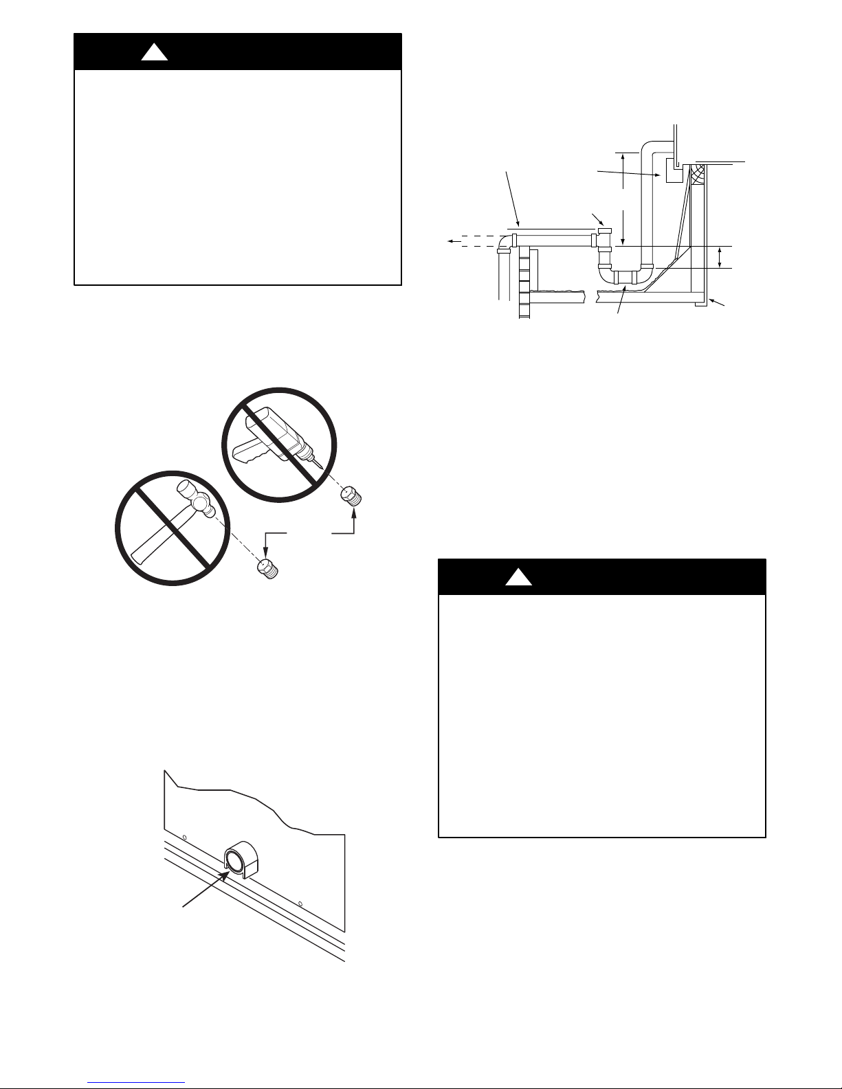
!
WARNING
FIRE HAZARD
Failure to follow this warning could result in
intermittent operation or unsatisfactory performance.
Do not connect aluminum wire between disconnect
switch and air conditioning unit. Use only copper
wire.(SeeFig.25.)
ELECTRIC
DISCONNECT
SWITCH
COPPER
WIRE ONLY
ALUMINUM
WIRE
A93033
Fig. 25 -- Disconnect Switch and Unit
26
Page 27

Fig. 26 -- 48LC 14--26 Electro--mechanical Control Wiring Diagram
a48--- 9336
27
Page 28

Fig. 27 -- 48LC 14--26 RTU Open Control Wiring Diagram
a48--- 9337
28
Page 29

Fig. 28 -- 48LC 14--26 SystemVut Control Wiring Diagram
a48--- 9338
29
Page 30

Fig. 29 -- Typical Power Wiring Diagram, Electro--mechanical and RTU Open Controls, 48LC 14--20 208/230V Shown
C14112
30
Page 31

Fig. 30 -- Typical Power W iring Diagram, SystemVut Controls, 48LC 26 208/230V Shown
a48--- 9339
31
Page 32

Units Without Factory--Installed Non--Fused
Disconnect or HACR —
When installing units, provide a disconnect switch per
NEC (National Electrical Code) of adequate size.
Disconnect sizing data is provided on the unit informative
plate. Locate on unit c abinet or within sight of the unit per
national or local codes. Do not cover unit informative
plate if mounting the disconnect on the unit cabinet.
Units With Factory--Installed Non--Fused Disconnect or
HACR—
The factory--installed option non--fused disconnect switch
(NFD) or HACR is located in the main control box. The
manual switch handle and shaft are shipped in the control
box and must be mounted on the corner post adjacent to
the control box (see Fig. 31 or 32). Note that the tape
covering the hole for the shaft in the corner post must be
removed prior to handle and shaft installation.
To field install the NFD shaft and handle:
1. Open the control box panel.
2. Make sure the NFD shipped from the factory is at
OFF position (the arrow on the black handle knob or
on the silver metal collar is at OFF).
3. Insert the shaft with the cross pin on the top of the
shaft in the horizontal position.
4. Measure the tip of the shaft to the outside surface of
the corner post to be 0.88”.
5. Tighten the locking screw to secure the shaft to the
NFD.
6. Turn the handle to OFF position with red arrow pointing at OFF.
7. Install the handle on to the corner post vertically with
the red arrow pointing up.
8. Secure the handle to the corner post with (2) screws
and lock washers supplied.
To field install the HACR shaft and handle:
1. Open the control box panel.
2. Make sure the HACR shipped from the factory is at
OFF position (the white arrow pointing at OFF).
3. Insert the shaft with the cross pin on the top of the
shaft in the horizontal position.
4. Measure the tip of the shaft to the outside surface of
the corner post to be 0.88”.
5. Tighten the locking screw to secure the shaft to the
HACR.
6. Turn the handle to OFF position with red arrow pointing at OFF.
7. Install the handle on to the corner post vertically with
the red arrow pointing up.
8. Secure the handle to the corner post with (2) screws
and lock washers supplied.
C12385
Fig. 31 -- Handle and Shaft Assembly for NFD
Fig. 32 -- Handle and Shaft Assembly for HACR
C12386
32
Page 33

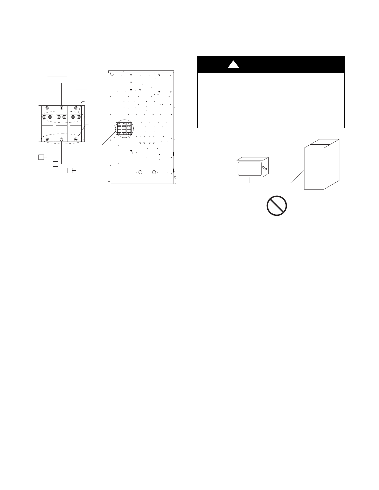
All Units --
All field wiring must comply with NEC and all local code
requirements.
Size wire based on MCA (Minimum Circuit Amps) on the
unit informative plate. See Fig. 33 for power wiring
connections to the unit power terminal block and equipment
ground. Maximum wire size is 2/0 AWG per pole.
Units Without Disconnect or HACR Option
TB1
11 1 3
12
Disconnect
per NEC
L1
L2 L3 Ground
208/230-3-60
460-3-60
575-3-60
Units With Disconnect or HACR Option
(GR)
Equip
GR Lug
!
CAUTION
UNIT DAMAGE HAZARD
Failure to follow this caution may result in equipment
damage.
Operation on improper line voltage or excessive phase
imbalance constitutes abu s e and may caus e damage to
electrical components. Such operation would invalidate
any applicable Carrier warranty.
Convenience Outlets —
!
WARNING
ELECTRICAL OPERATION HAZARD
Failure to follow this warning could result in personal
injury or death.
Units with convenience outlet circuits may use
multiple disconnects. Check convenience outlet for
power status before opening unit for service. Locate
its disconnect switch, if appropriate, and open it.
Lock--out and tag--out this switch, if necessary.
Factory
Wiring
T1
T2 T3
Optional
Disconnect
Switch
or HACR
L1 L2 L3
L1 L2 L3
Equip
GR Lug
Ground
(GR)
C12387
Fig. 33 -- Power Wiring Connections
Provide a ground--fault and short--circuit over--current
protection device (fuse or breaker) per NEC Article 440
(or local codes). Refer to unit informative data plate for
MOCP (Maximum Over--current Protection) device size.
NOTE: Units ordered with factory--installed HACR do
not need additional ground--fault and short circuit ove r
current protection devic e unless required by local codes.
Voltage to compressor terminals during operation must be
within voltage range indicated on unit nameplate. See
Tables 26 and 27. On 3--phase units, voltages between
phases must be balanced within 2% and the current within
10%. Use the formula shown in the legend for Tables 26
and 27 (see Note 3 on page 79) to determine the percent
of voltage imbalance.
Tw o types of convenience outlets are offered on 48LC
models: Non--unit powered and unit--powered. Both types
provide a 125--volt GFCI (ground--fault circuit--interrupter)
duplex receptacle rated at 15--A behind a hinged access
cover, located on the corner panel of the unit. See Fig. 34.
Control Box
Access Panel
Electric
Disconnect
Switch
Convenience
Outlet
C10641
Fig. 34 -- Convenience Outle t Location
Installing Weatherp roof Cover: A weatherproof
while-in-use cover for the factory-installed convenience
outlets is now required by UL standards. This cover cannot
be factory-mounted due to its depth; it must be installed at
unit installation. For shipment, the convenience outlet is
covered with a blank cover plate.
The weatherproof cover kit is shipped in the unit’s control
box. The kit include s the hinged cover, a backing plate
and gasket.
DISCONNECT ALL POWER T O UNIT AND
CONVENIENCE OUTLET. LOCK--OUT AN D TAG--OUT
ALL POWER.
Remove the blank cover plate at the convenience outlet;
discard the blank cover.
33
Page 34

Loosen the two screws at the GFCI duplex outlet, until
1
approximately
/2-in. (13 mm) under screw heads are
exposed. Press the gasket over the screw heads. Slip the
backing plate over the screw heads at the keyhole slots
and align with the gasket; tighten the two screws until
snug (do not over-tighten).
Mount the weatherproof cover to the backing plate as
shown in Fig. 35. Remove two slot fillers in the bottom of
the cover to permit service tool cords to exit the cover.
Check for full closing and latching.
COVER – WHILE-IN-USE
WEATHERPROOF
RECEPTACLE
NOT SHOWN
BASE PLATE FOR
GFCI RECEPTACLE
C09022
Fig. 35 -- Weatherproof Cover Installation
Non--unit powered type: This type re quires the field
installation of a general--purpose 125--volt 15--A circuit
powered from a source elsewhere in the building. Observe
national and local codes when sel ecting wire size, fuse or
breaker requirements and disconnect switch size and
location. Route 125--v power supply conductors into the
bottom of the utility box containing the duplex receptacle.
Code Article 210, Branch Circuits, for use of convenience
outlets.
C10730
UNIT
VOLTAGE
208,
230
460 480
575 600
CONNECT
AS
240
PRIMARY
CONNECTIONS
L1: RED +YEL
L2: BLU + GRA
L1: RED
Splice BLU + YEL
L2: GRA
L1: RED
L2: GRA
TRANSFORMER
TERMINALS
H1 + H3
H2 + H4
H1
H2 + H3
H4
H1
H2
Unit--powered type: A unit--mounted transformer is
factory--installed to stepdown the main power supply
voltage to the unit to 115--v at the duplex receptacle. This
option also includes a manual switch with fuse, located in
a control box and mounted on a bracket behind the
convenience outlet; access i s through the unit’s control
box access panel. See Fig. 34.
The primary leads to the convenience outlet transformer
are not factory--connected. If local codes permit, the
transformer primary leads can be connected at the
line--side terminals on the unit--mounted non--fused
disconnect switch; this will provide service power to the
unit when the unit disconnect switch is open. See Fig. 36.
Test the GFCI receptacle by pressing the TEST button on
the face of the receptacle to trip and open the receptacle.
Check for proper grounding wires and power line phasing
if the GFCI receptacle does not trip as required. Press the
RESET button to clear the tripped condition.
Using unit--mounted convenience outlets: Units with
unit--mount ed convenience outlet circuits will often
require that two disconnects be opened to de--energize all
power to the unit. Treat all units as electrically energized
until the convenience outlet power is also checked and
de--energization is confirmed. Observe National Electrical
Fig. 36 -- Powered Convenience Outlet Wiring
NOTICE/AVIS
Convenience Outlet Utilization
Maximum Intermittent Use 15 - Amps
Maximum Continuous Use 8 - Amps
Observe a 50% limit on the circuit
Loading above 8 - Amps
Utilisation de la prise utilitaire
Usage intermittent maximum 15 - Amps
Usage continu maximum 8 - Amps
Observez une limite de 50% sur le circuit
Chargement au-dessus de 8 - Amps
Fig. 37 -- Convenience Outlet Utilization Notice
HACR —
The amp rating of the HACR factory--installed option is
based on the size, voltage, indoor motor and other
electrical options of the unit as shipped from the factory.
If field--installed accessories are added or changed in the
field (i.e., power exhaust), the HACR may no longer be of
the proper amp rating and therefore will need to be
removed from the unit. See unit nameplate and label on
factory--installed HACR for the amp rating of the HACR
that was shipped with the unit from the factory. See unit
2.050HE501288
C10077
34
Page 35

nameplates for the proper fuse, HACR or maximum
over--current protection device required on the unit with
field--installed accessories.
C12105
Fig. 38 -- HACR Caution Label
Factory--Option Thru--Base Connections —
All units are equipped with the ability to bring utilities
through the base.
Gas is brought up through an embossed area located in the
gas section behind the gas entrance post. Access is gained
through the gas access panel. A knock out must be
removed to accomplish this.
The electrical entrance is located in the control box area
and can be accessed through the control box access panel.
An embossed area is provided with three knock outs. High
voltage is brought through the multi knock out by
removing the appropriate size for the size of the fitting
7
required. A
An additional
/8--in. knock out is provided for low voltage.
7
/8--in. knock out is provide d for a 115 volt
line which is used when the unit is equipped with the
non--unit powered convenience outlet option.
All required fittings are field supplied. Install fittings
when access to both top and bottom of the base pan is
available. See electrical and gas connections for routing
and connection information.
Units Without Thru--Base Connections —
1. Install liquid tight conduit between disconnect and
control box.
2. Pull correc tly rated high voltage wires through the
conduit.
3. Install power lines to terminal connections as shown
in Fig. 33.
Field Control Wiring —
The 48LC unit requires an external t emperature control
device such as a thermostat (field--supplied).
Thermostat —
Install a Carrier--approved accessory 3--stage thermostat
according to installation instructions included with the
accessory. If a 3--stage cooling thermostat is not available
use a 2--stage cooling thermostat instead, but note that this
will limit cooling to just 2 stages. Locate the thermostat
accessory on a solid wall in the conditioned space to sense
average temperature in accordance with the thermostat
installation instructions.
If the thermostat contains a logic circuit requiring 24--v
power, use a thermostat cabl e or equivalent single leads of
different colors with minimum of eight leads. If the
thermostat does not require a 24--v source (no “C”
connection required), use a t hermostat cable or equivalent
with minimum of seven leads. Check the thermostat
installation instructions for additional features which
might require additional conductors in the cable.
For wire runs up to 50 ft (15 m), use no. 18 AWG
(American Wire Gage) insulated wire (35_C minimum).
For 50 to 75 ft (15 to 23 m), use no. 16 AWG insulated
wire (35_C minimum). For over 75 ft (23 m), use no. 14
AWG insulated wire (35_C minimum). All wire sizes
larger than no. 18 AWG cannot be directly conne cted to
the thermostat and will require a junction box and splice
at the thermostat.
Unit Without Thru--Base Connection Kit —
Correctly rated l ow voltage wire can be routed through the
rubber grommet located on the corner post adjacent to the
control box access panel. Route wire through the grommet
and then route the wire behind the corner post utilizing the
factory provided wire ties secured to the control box. This
will insure separation of the field low voltage wire and the
high voltage circuit. Route the low voltage wire to the
Integrated Staging Control (ISC) board. See Fig. 39.
Typical
Thermostat
Connections
C
W1
W2
G
Y3
O/B/Y2
(Note 1)
Y1
R
Note 1: Typical multi-function marking. Follow manufacturer’s configuration
Instructions to select Y2.
Note 2: Y2 to Y3 connection required for 2-stage cooling operation and when
integrated economizer function is desired.
Note 3: To Connect a 2-Stage Thermostat:
Y2 to Y3 connection required for 2-stage cooling operation which
provides low and high cooling states.
Note 4: SystemVu
2-stage heating thermostats; it can be configured for other thermostat types.
Field Wiring
(Note 3 & 4)
(Notes 2, 3 & 4)
controller is default configured for 3-stage cooling and
Integrated Staging Control
(ISC) Board or
SystemVu
C
W1
W2
G
Y3
Y2
Y1
R
TM
Controller
T
H
E
R
M
O
S
T
A
T
a48--- 9346
Fig. 39 -- Typical Low--Voltage Control Connections
35
Page 36

NOTE: If utilizing the through the base connections,
route the low voltage wire through the wire ties to the
Integrated Staging Control (ISC) board (see Fig. 40).
Rubber
Grommet
Corner
Post
Heat Anticipator Settings —
Set heat anticipator settings at 0.14 amp for the first stage
and 0.14 amp for second--stage heating.
Transformer Connection for 208--v Power Supply —
All units except 208/230-v units are fa ctory wired for the
voltage shown on the nameplate. If the 208/230-v unit is
to be connected to a 208-v power supply, the control
transformer must be rewired by moving the black wire
1
with the
connection and moving it to the 208-v
/4-in. female spade connector from the 230-- v
1
/4-in. male
terminal on the primary side of the transformer. Refer to
unit label diagram for additional information.
RTU Open Controller (Factory--Installed Option)
Wire
Ties
Thru the Base
Connection
Fig. 40 -- Field Control Wiring Raceway
C10734
For details on operating 48LC*014--26 units equipped
with the factory--installed RTU Open option refer to
48/50LC 07--26 F actory Install ed Option RTU Open
Multi--P rotocol Controller Controls, Start--up, Operation
and Troubleshooting.
SystemVut Controller (Factory--Installed Option)
For details on operating 48LC*014-26 units equipped with
the factory-installed SystemVu control option refer to
48/50LC 04-26 Single Package Rooftop Units with
SystemVu Controls Version 2.X Controls, Start-up,
OperationandTroubleshootingmanual.
618
36
Page 37

Humidi--MiZerRSystem Control Connections
NOTE: It is suggested to ensure the Auto--Changeover
function of an installed thermostat is enabled when used
in conjunction with the Humidi--MiZer Adaptive
Dehumidification system.
Humidi--MiZer System – Space RH Controller —
The Humidi--MiZer dehumidification sys tem requires a
field--supplied and installed space relative humidity contr ol
device. This device may be a separate humidistat control
(contact closes on rise in space RH above control setpoint)
or a combination thermostat--humidistat control device with
isolated contact set for dehumidification control.
NOTE: Use of a humidistat device is not permitted on
48LC units equipped with R TU Open control; these units
require use of a field--supplied RH sensor
(33ZCSENSRH--02 or 33ZHCSENDRH--02), or a ZS series
sensor with humidity sensing. SystemVut controls requires
a Space Humidistat (HL38MG029) or a W all Mount Space
Humidity Sensor (33ZCSENSRH--01) or a Duct Mount
Humidity Sensor (33ZCSENDRH--01).
To connect the Carrier humidistat (HL38MG029):
1. Route the humidistat 2--conductor cable (field--supplied)
through the hole provided in the unit corner post.
2. Feed wires through the raceway built into the corner
post (see Fig. 40) to the 24--v barrier located on the
left side of the control box. The raceway provides the
ETL--required clearance between high--voltage and
low--voltage wiring.
3. Us e wire nuts to connect humidistat cable to two PINK
leads in the low–voltage wiring as shown in Fig. 42.
% RELATIVE HUMIDITY
C09295
Fig. 41 -- Accessory Field--Installed Humidistat
NOTE: 48LC**014 -- 26 units require a 3--stage cooling
thermostat device and are not compatible with Carrier’s
R
Edge
Pro thermidistat.
Humidistat
Fig. 42 -- Typical Humidi--MiZer Adaptive Dehumidification System Humidistat Wiring
C14113
37
Page 38

Integrated Staging Control (ISC) Board
Economizer
DDC
Control
DDC
Control
Indoor Fan
“On” Status
IGC
Board
Power
Plug
Phase
Phase
Monitor
Monitor
Relay
Relay
Auxilary
Shutdown
Condensate
Overflow
Remote
Shutdown
Smoke
Shutdown
Smoke
Alarm
Occupancy
Status Code LEDs
Thermostat
Outdoor Fan
Motors
Fig. 43 -- Integrated Staging Control (ISC) Board
ISC Board -- Sequence of Operation
General —
The Carrier Integrated Staging Control (ISC) is inte nded
for use with a standard thermostat or direct digital controls
(DDC) capable of three cooling stages. After initial power
to the board, a Green LED will blink with a 1 second duty
cycle indicating the unit is running properly. In the event
of the ISC board failing, the Green LED will be OFF or
continuously ON. When the unit is not running properly,
the Green LED will blink along with Red LED lights. The
Red LED light configuration will indicate the t ype of
error the board has identified. See Fig. 43 for LED
locations and Table 7 for a list of status codes.
The ISC board can be remotely shutdown by removi ng
Jumper 4 and wiring to the Remote Shutdown terminal.
The Smoke Control Module can shutdown the unit by
removing Jumpe r 3 and wiring to the Smoke Shutdown
terminal. The Smoke Alarm terminal on the ISC Board
Low Ambient
Outdoor Fan
Control
Compressors
Reheat
Low-Pressure
Switch
Indoor Fan
Motor
High-Pressure
Switch
a48--- 9321
provides a pass thru connection should a smoke alarm
signal be connected. In the case of the RTU Open option,
the RTU Open controller provides the signal which is
passed thru the ISC board to the Smoke Alarm terminal.
The crankcase heater will run at all times except when the
compressors are running. An auxiliary power supply
(24Vac) available at TB--4 Terminal is provided to power
auxiliary equipment. An optional Phase Monitor Relay
can be wired to the PMR terminal by removing Jumpe r 5.
An optional Condensate Flow Switch can be wired to the
COFS Terminal by removing Jumper 7.
Ventilation —
In the Ventilation/Fan Mode (G on the thermostat), the
indoor--fan will run at low speed and the damper will
operate at minimum position.
38
Page 39

Table 7 – Status Code Descriptions for ISC Board LEDs
ERROR# ERROR NAME
1 Check Smoke Detector/PMR/AUX RED
2 Check HPS/LPS/COFS RED RED
3 Call for Y3 with no call for Y1. Check Y1 wiring. RED
4 Call for Y3 with no call for Y1/Y2. Check Y1 wiring. RED RED
5 Call for Y2 with no call for Y1. Check Y1 wiring. RED RED
6 Call for W2 with no call f or W1. Check W1 wiring. RED RED
7 Call for heat (W1/W2) and cooling (Y1/Y2/Y3). Check thermostat wiring. RED RED RED RED
8 Call for heat (W1/W2) with no IFM. Check G wiring. RED RED RED
9 Call for cooling (Y1/Y2/Y3) with no G. Check G wiring RED RED RED
Call for heat (W1/W2) and cooling (Y1/Y2/Y3) with no G.
10
Check thermostat and G wiring.
11 Check ISC Board and the thermostat wiring RED RED RED
Call for Economizer Y1 Feedback (ECON) from economizer with no call
12
for Y1 from thermostat. Check thermostat and economizer wiring.
13 Check ISC Board and the thermostat wiring RED RED
14 Check ISC Board and the thermostat wiring RED
15 Check ISC Board and the thermostat wiring RED RED
NOTES: 1. Green LED Blinking at 1HZ indicates normal operation.
2. Solid red LED indicates an error exists, see above LED configuration.
LED01 LED02 LED03 LED04 LED05
RED RED RED
RED
LED INDICATION
Blinking
Green
LED
(Note 1)
Cooling —
In the Cooling Mode, the small and large compressors will
be sequenced to maintain the thermostat temperature
setpoint. The chart below shows the cooling operation
based on t he following conditions.
INPUT OUTPUT
Thermostat
First Stage Cooling
(Y1)
Second Stage Cooling
(Y2)
Third Stage Cooling
(Y3)
Compresso rC1Compresso r
On Off Low
Off On Medium
On On High
C2
Indoor
Fan
Speed
Outdoor
Fan
Speed
Low
(700 rpm)
Medium
(800 rpm)
High
(1000 rpm)
The outdoor fan and VFD controlled indoor--fan will
operate at low, medium and high speed. The indoor-- fan
speed (rpm) is factory set by the CFM and static pressure
requirements for the unit installed.
R
Humidi--MiZer
System (Optional) —
In the Dehumidification Mode, both compressors will run
and Indoor a irflow will be rise to High Speed.
At subcooler reheating mode (reheat--1), during part load
conditions when the room tempera ture and humidity are
above the set point, the unit initiates the sub--cooling
mode of operation; a call for cooling and
dehumidificat ion. RDV (Reheat Discharge Valve) and
TWV (Three Way Valve) close; Indoor and Outdoor
airflow will rise until reaching 100% of Speed.
At hot--gas--bypass reheating mode (reheat--2), when there
is a call for dehumidification without a call for cooling, a
portion of the hot gas from the com pressor bypasses the
condenser coil when RDV opens and hot gas is fed into
the liquid line, TWV closes in this mode and the system
provides mainly latent cool ing. Indoor a irflow will rise
until reaching 100% of Speed, Outdoor airflow will run at
High speed as long as outdoor temperature is above 80_F
(26.7_C); when operating in this mode be low 80_F
(26.7_C) OAT, the system outdoor fan will operate as
shown in the table below based on Size:
LC Size RPM Number of Fans On Number of Fans Off
14 250 3 0
17 250 4 0
20 160 4 0
24 250 6 0
26 250 6 0
Economizer (Optional) —
When the economizer is in Free Cooling Mode and a
demand for cooling exists (Y1 on the thermostat), the
economizer will modulate the outdoor--air damper to
provide a 50_F(10_C) to 55_F(13_C) mixed--air
temperature into the zone and run the indoor--fan at high
speed. As mixed--air temperature fluctuates above 55 ºF
(13_C) or below 50_F(10_C) dampers will be modulated
(open or close) to bring the mixed--air temperature back
within control. Upon more call for cooling (Y2 on the
thermostat), the outdoor--a ir damper will maintain its
current position, compressor C1 will run and the
outdoor--fan will run at l ow speed. If there is further
demand for cooling, the outdoor--air damper will maintain
its current position, compressor C2 will run and the
outdoor--fan will run at medium speed. The VFD
controlled indoor--fan will operate at high speed
regardless of the cooling demand.
If the increase in cooling capacity causes the mixed--air
temperature to drop below 45_F(7_C), the outdoor--air
damper will return to the minimum position. If the
mixed--a ir temperature continues to fall, the outdoor--air
damper will close. Control returns to normal once the
mixed--a ir tem perature rises above 48_F(9_C). The
power exhaust fans will be energized and de--energized, if
installed, as the outdoor--air damper opens and closes.
39
Page 40

In field--installed accessory CO2sensors are connected to
the Economizer, a demand controlled ventilation strategy
will begin to operate. As the CO
increases above the CO
set--point, the minimum position
2
level in the zone
2
of the damper will be increased proportionally. As the
level decreases because of the increase of fresh air,
CO
2
the outdoor--air damper will be proportionally closed. For
economizer operation, there must be a thermostat call for
the fan (G). If the unit is occupied and the fan is on, the
damper will operate at minimum position. Otherwise, the
damper will be closed.
Low Ambient Cooling Operation Down to 40_F(4_C)—
In Low Ambient RTU conditions when the temperature is
between 55_F(13_C) and 40_F(4_C), the Low Ambient
Switch (LAS) will be active and the outdoor fans will run
to the pre--set factory outdoor--fan speed. When the
temperature is greater than 65_F(18_C), the Low
Ambient Switch will deactivate and the outdoor fans will
run in the standard cooling mode. If the Outdoor Fan
Select Switch (see Fig. 44) is in the ON position, the
outdoor fans will run in the Fan Cycle Speed Mode (FCS)
set to 250 rpm. If the Outdoor Fan Select Switch is in the
OFF posit ion, the outdoor fans will run in the Minimum
Fan Speed Mode (MIN) set to 160 rpm regardless of the
cooling demand.
LC Size 14 through 26 units have a SPST normally open
Low Ambient Switch wired acros s the TS and OF terminal
and a jumper placed across the PS terminal (see Fig. 45).
When the LAS is active, the switch will clos e making
contact to the OF terminal. This is done for units that require
all outdoor fans to run at the same pre--set factory Low
Ambient Speed.
OF SPEED
SELECT
ON
FCS
MIN
OFF
a48--- 9341
Fig. 44 -- Outdoor Fan Speed Select Switch
JUMPER ON
PS PS
TS OF
LAS
SPST
C13328
Fig. 45 -- Schematic of SPST Low Ambient Switch
The Low Ambient Tempera ture Outdoor Fan Control
Table (below) shows the operation of the outdoor fan for
each unit.
T able 8 – Low Ambient Temperatur e Outdoor Fan Control
LC Size
14 3 0 SPST Up 250
17 4 0 SPST Up 250
20 4 0 SPST Up 250
24 6 0 SPST Up 250
26 6 0 SPST Up 250
No. of
Fans On
No. of
Fans Off
Switch
Outdoor Fan
Select Switch
RPM
Heating —
In the Heating Mode (W1 and G on the thermostat), the
ISC board sends power to W on the IGC boa rd. Assuming
the unit is controlled through a room thermostat set for fa n
auto, the indoor--fan motor will energize and the
outdoor--air dampers will open to t heir minimum position.
The ISC board upon seeing W1 and G ON will turn the
indoor fan to high speed.
The IGC board starts its gas ignition process. A check is
made to ensu re that the rollout sw itch and limit switch are
closed. If the check was successful, the induced draft motor is
energized, and when its speed is satisfactory, as proven by the
flue gas pressure switch, the ignition activation period begins.
The burners will ignite within 5 seconds. If the burners do not
light, there is a 22--second delay before another 5--second
attempt. This sequence is repeated for 15 minutes or until the
burners light. If, after the 15 minutes, the burners still have
not lit, heating is locked out. To reset the control, break
24VAC power to the thermostat.
When gas ignition occurs, the IGC board will continue to
monitor the condition of the rollout switch, the limit
switches, the flue gas pressure switch, as well as the flame
sensor.
When W1 is turned OFF, the IGC board turns off the gas
valve. The IGC board has a delay time before it turns
IFO=OFF. At this time, the ISC board sees W1=OFF and
IFO=ON. The ISC will keep the indoor fan ON high
speed. Once the IGC board delay times out, the ISC board
will see W1=OFF and IFO=OFF, which then turns the
indoor fan OFF.
If the call for W1 lasted less than 1 minute, the heating
cycle will not terminate until 1 minute after W1 became
active. If the unit is controlled through a room thermostat
set for fa n auto, the indoor fan motor will continue t o
operate for a n additional 45 seconds then stop. If the over
temperature limit opens after the indoor motor is stopped,
but within 10 minutes of W1 becoming inactive, on the
next cycle the time will be extended by 15 seconds. The
maximum delay is 3 minutes. Once modified, the fan OFF
delay will not change back to 45 seconds unless power is
reset to the control. A LED indicator is provided on t he
IGC to monitor operation.
When additional heat is required, W2 closes and initiates
power to the second stage of the main gas valve. When
the thermostat is satisfied, the gas valve closes,
interrupting the flow of gas to the main burners.
40
Page 41

EconoMi$erRX (Factory--Installed Option)
EconoMi$er X is an economizer system which is available
for 48LC 14--26 units.
The factory--installed option consists of:
S Either a Low leak or a Standard leak economizer
damper assembly
S Direct--drive damper actuator with local equipment bus
communications
S W7220 ec onomizer controller with keypad and display
S Supply Air Temperature sensor (20K ohm)
S Outdoor changeover condition sensor (either 20K ohm
dry--bulb or enthalpy sensor)
Unit Installation —
All damper hardware and standard economizer control
components except the enthalpy sensor are factory--mounted
in their operating location. Complete the unit installation by
relocating the enthalpy sensor (when provided; see below),
then assembling and mounting the unit’s outside air hood.
Refer to the base unit’s installation instruction manual for
directions on locating the hood parts package and
assembling the hood with filters.
Enthalpy Sensor Relocation —
See Fig. 54 for view of the enthalpy sensor. Locate the
enthalpy sensor on the side of the economizer housing;
remove mounting screws and save screws. Confirm the DIP
switches are set at OFF, OFF, OFF (see Table 16). Move the
enthalpy sensor to the front face of the economizer housing
and mount per label.
W7220 Economizer Controller
The economizer controller used on electro mechanical units
is the Honeywell W7220.
The W7220 provides typical economizer functions,
including:
S Management of outside air damper for base unit
Occupied (damper open and modulating) and unit OFF
or Unoccupied status (damper closed)
S Free--cooling using all out side air when out door
conditions permit Integrated cooling operation using
outside air and mechanical cooling when required
S Demand Controlled Ventila tion (DCV) for modulating
ventilation airflow according to space CO
(requires factory--option or field --installed CO
The W7220 control also includes a new capability that will
adjust the damper control points during DCV or minimum
ventilation operation as the indoor fan speed is changed.
This control function ensures that required space ventilation
airflow quantities are maintained during redu ced fan speed
operation.
Additional control capabilities include automatic detection of
new sensors and detection of sensor failure or loss of
communication.
2
level
2
sensor)
The W7220 control module includes an integral user
interface with keypad and LCD display that permits direct
input of setpoint values and configurations and display of
status and alarms.
The W7220 controller is located in the RTU base unit’s
Control Box. See the Installation Instructions for this base
unit for the location of the Control Box access panel.
User Interface —
The user inte rface consists of a 2--line LCD display and a
4--button keypad on t he front of the economizer controller.
2 LINE
LCD
MENU UP
(EXIT)
BUTTON
SCROLL
UP/DOWN
BUTTONS
SELECT
(ENTER)
BUTTON
C14206
Fig. 46 -- W7220 Controller
Keypad
The four navigation buttons (see Fig. 46) are used to scroll
through the menus and menu items, select menu items,
and to change parameter and configuration settings.
Using the Keypad with Menus
To use the keypad when working with menus:
S Press the
(Up arrow) button to move to the previous
menu.
S Press the
(Down arrow) button to move to the next
menu.
S Press the
(Enter) button to display the first item in
the currently displayed menu.
S Press the
(Menu Up/Exit) button to exit a menu’s
item and return to the list of menus.
The Menus in display order are:
S STATUS
S SETPOINTS
S SYSTEM SETUP
S ADVANCED SETUP
S CHECKOUT
S ALARMS
41
Page 42

Using the Keypad with Settings and Parameters
To use the keypad when working with Setpoints, System
and Advanced Settings, Checkout tests and Alarms:
9. Press the
menu parameter.
10. Press the (MenuUp/Exit)buttontoreturntothe
previous menu.
1. Navigate to the desired menu.
2. Press the
the currently displayed menu.
3. Use the
rameter.
4. Press the
currently displayed item.
5. Press the
(Enter) button to display the first item in
and buttons to scroll to the desired pa-
(Enter) button to display the value of the
button to increase (change) the displayed
Menu Structure
IMPORTANT : Tab le 9 illustrates the complete hierarchy.
Your menu parameters may be different depending on
your configuration. For example if you do not have a
DCV (CO
appear .
) sensor, then none of the DCV parameters
2
parameter value.
6. Press the
button to dec r ease (change) the displayed
parameter value.
NOTE: When values are displayed, pressing and
holding the
or button ca uses the
display to automatically increment.
7. Press the
(Enter) button to accept the displayed
value and store it in nonvolatile RAM.
8. “CHANGE STORED” displays.
The menu hierarchy has been modified to reflect controller
configuration for 2--speed indoor fan application in the
Staged Air V olume option.
NOTE: Some parameters in the menus use the letters MA
or M AT, indicating a mixed air temper atur e sensor location
before the cooling coil. This unit application has the control
sensor located after the cooling coil, in the fan section,
where it is designated as (Cooling) Supply Air Temperature
or SAT sensor.
Table 9 – Menu Structure*
Parameter
Menu Para meter
STATUS ECON AVAIL NO YES/NO ECONOMIZING AVAILABLE
ECONOMIZING NO YES/NO ECONOMIZING ACTIVE
OCCUPIED NO YES/NO OCCUPIED
HEAT PUMP n/a** COOL
COOL Y1 - -- IN OFF ON/OFF FIRST STAGE COOLING D EMAND (Y1 ---IN)
COOL Y1 - -- OUT OFF ON/OFF FIRST STAGE COOLING RELAY OUTPUT
COOL Y2 - -- IN OFF ON/OFF SECOND STAVE COOLING DEMAND (Y2- -- IN)
COOL Y2 - -- OUT OFF ON/OFF SECOND STAGE COOLING RELAY OUT PUT
MA TEMP nn_F(or_C) 0 to 140_F
DA TEMP nn _F(or_C) 0 to 140_F
OA TEMP nn_F(or_C) --- 40 to 140_F
OA HUM nn% 0 to 100% OUTSIDE AIR RELATIVE HUMIDITY
RA TEMP nn_F(or_C) 0 to 140_F
Default
Value
Parameter
Range and Increment
HEAT
(---18 to 60_C)
(---18 to 60_C)
(---40 to 60_C)
(---18 to 60_C)
{
YES = economizing available; the system can use outside air for free
cooling when required
YES = Outside air being used for Cooling Stage 1.
NO = Economizi ng not active
YES = OCC signal received from space thermostat
or unitary controller.
YES = 24 Vac on terminal OCC.
NO = 0 Vac on terminal OCC.
HEAT PUMP MODE
(Not available on 2- -- Speed configuration)
Y1---I signal from space thermostat or unitary controller for Cooling Stage 1.
ON = 24 Vac on terminal Y1- -- I
OFF = 0 Vac on terminal Y1- -- I
ON = 24 Vac on terminal Y1- -- O; Stage 1 mechanical cooling called on
OFF = 0 Vac on terminal Y1 - --O; no mechanical cooling
Y2---I signal from space thermostat or unitary controller for Cooling Stage 2.
ON = 24 Vac on terminal Y2- -- I
OFF = 0 Vac on terminal Y2- -- I
ON = 24 Vac on terminal Y2- -- O; Stage 2 mechanical cooling called on
OFF = 0 Vac on terminal Y2- --O; no Stage 2 mechanical cooling
SUPPL Y AIR TEMPERATURE, Cooling Mode
Displays value of measured mixed/cooled air from SAT sensor in fan
section.
D isp l a y s --- --- . --- if n o t c o n n e c t e d, s h o r t o r o u t --- of --- r a n g e . S e e M e n u N o t e 2
DISCHARGE AIR TEMPERA TUR E, after Heating section
(Accessory sensor required)
Displays wh en Discharge Air sen sor is connected and displays measured
discharg e temperat ure.
D isp l a y s --- --- --- --- --- --- if s e n s o r sen ds i n v a l i d v a l u e , i f n o t connecte d , s h o r t
or out---of- --range.
OUTSIDE AIR TEMPE RATURE
Displays measured value of outdoor air temperature.
D isp l a y s --- --- --- --- --- --- if s e n s o r sen ds i n v a l i d v a l u e , i f n o t connecte d , s h o r t
or out---of- --range.
Display s measured value of outdoor humidity from OA enthalpy sensor.
RETURN AIR TEMPERATURE
(Accessory sensor required)
Displays measured value of return air temperature from RAT sensor.
EXPAN DED PARAM ETER NAME
42
(Enter) button to return to the current
Notes
Page 43

Menu Para meter
Parameter
STATUS
RA HUM nn% 0 to 100% RETURN AIR RELATIVE HUMIDITY
(cont)
IN CO2 ___ppm 0 to 2000 ppm SPACE/RETURN AIR CO2
DCV STATUS n/a ON/OFF DEMAND CONTRO LLED VENTILATION STATUS
DAMPER OUT 2.0V 2.0 to 10.0V Disp lays voltage output to the damper actuator .
ACT POS nn% 0 to 100% Displays actual position of outdoor air damper actuator
ACT COUNT n/a 1 to 65535 Displays number of times actuator has cycled.
ACTUATOR n/a OK /Alarm
EXH1 OUT OFF ON/OFF EXHAUST STAGE 1 RELAY OUTPUT
EXH2 OUT OFF ON/OFF EXHAUST STAGE 2 RELAY OUTPUT
MECH COOL ON 0 0, 1, or 2 Displays stage of mechanic al cooling that is active.
FAN SPEED n/a LOW or HIGH SUPPLY FAN SPEED
W(HEATON) n/a ON/OFF HEAT D EM AND STATUS
SETPOINTS MAT SET 53_F
(12_C)
LOW T LOCK 32_F
(0_C)
DRYBLB SET 63_F
(17_C)
ENTH CURVE ES3 ES1, ES2, ES3, ES4, or
DCV SET 1100ppm 500 to 2000 ppm;
MIN POS L 6.0 V 2to10Vdc VENTILATION MINIMUM POSITION AT LOW SPEED
MIN POS H 4.4 V 2to10Vdc VENTILATION MINIMUM POSITION AT HIGH SPEED
VENTMAX L 6.0 V 2to10Vdc DCV MAXIMUM DAMPER POSI TION AT LOW SPEED
VENTMAX H 4.4 V 2to10Vdc DCV MAXIMUM DAMPER POSITI ON AT HIGH SPEED
VENTMIN L 3.7 V 2to10Vdc DCV MINIM UM DAMPER POSITION AT LOW SPEED
VENTMIN H 2.8 V 2to10Vdc DCV MINIMUM DAMPER POSITION AT HIGH SPEED
EXH1 L SET 65% 0 to 100%;
EXH1 H SET 50% 0 to 100%;
Default
Value
Table 9 -- Menu Structure* (cont)
Parameter
Range and Increment
(on Alarm menu)
38 to 65_F;
(3 to 18_C)
increment by 1
---45 to 80_F;
(---43 to 27_C)
increment by 1
48 to 80_F
(9 to 27_C)
increment by 1
ES5
increment by 100
Increment by 1
Increment by 1
{
(Accessory enthal py sensor required)
Display s measured value of return air humidi t y from RA sensor .
(CO
sensor required, accessory or factory option)
2
Displays value of measured CO
Invalid if not connected, short or out ---of ---range
sensor required, accessory or factory option)
(CO
2
Display s ON if IN CO
setpoint DCV SET.
0% = OSA Damper fully closed
100% = OSA Damper full open
2.0V = OSA Damper fully ---closed
10.0V = OSA Damper full open
1 Cycle equals accrued 180_ of actuator movement in any direction
Displays Error if voltage or torque is below actuator range
Output of EXH1 terminal:
ON = relay closed
OFF = relay open
Output of AUX terminal; displays only if AUX = EXH2
ON = relay closed
OFF = relay open
Displays speed setting of fan on a 2 -- -speed fan unit.
Displa ys status of heat demand on a 2---speed fan unit.
SUPPLY AIR SETPOINT
Setpoint determines where the economizer will modulate the OA damper to
maintain the mixed air temperature.
SeeMenuNote2.
COMPRESSOR LOW TEMPERATURE LOCKOUT
Setpoint determines outdoor temperature when the mechanical cooling
cannot be turned on.
OA DRY BULB TEMPERATURE CHANGEOVER SETPOINT
Setpoint determines where the economizer will assume outdoor air
temperature is good for free cooling; e.g.: at 63_F(17_C), unit will
economize at 62_F (16.7_C) and below and not economize at 64_F
(17.8_C) and above. There is a 2_F(1.1_C)deadband.
SeeMenuNote3
ENTHALPY CHANGEOVER CURVE
(Requi res enthalpy sensor option)
Enthalpy boundary “curves” for economizing using single enthalpy.
DEMAND CONTROLLED VENTILA TION SETPOINT
Displays only if CO
Ventilation of space. Above the setpoint, the OA dampers will modulate
open to bring in additional OA to maintain a space ppm level below the
setpoint.
Display s ONLY if a CO
Display s ONLY if a CO
(Requires CO
(Requires CO
(Requires CO
(Requires CO
EXHAUST FAN STAG E 1 SETPOINT AT LOW SPEED
Setpoi nt for OA damper position when exhaust fan1 is powered by the
economizer
EXHAUST FAN STAGE 1 SETPOINT AT HIGH SPEED
Setpoi nt for OA damper position when exhaust fan1 is powered by the
economizer
EXPAN DED PARAM ETER NAME
Notes
from CO2sensor.
2
value above setpoint DCV SET and OFF if below
2
sensor is connected . Setpoint for Demand Controlled
2
sensor is NOT connected.
2
sensor is NOT connected.
2
sensor connect e d )
2
sensor connect e d )
2
sensor connect e d )
2
sensor connect e d )
2
43
Page 44

Menu Para meter
SETPOINTS
(cont)
SYSTEM
SETUP
ADVANCED
SETUP
EXH2 L SET 80% 0 to 100%;
EXH2 H SET 75% 0 to 100%;
INSTALL 01/01/10 Display order = MM/DD/YY
UNITS DEG _F _For_C Sets economizer controller in degrees Fahrenheit or Celsius.
EQUIPMENT CONV Conventional or HP CONV = conventiona l;
AUX 2 I W W required for 2 ---speed
FAN TYPE 2speed 2speed required Sets the economizer controller for operation of 1 speed or 2 speed indoor
FAN CFM 5000cfm 100 to 15000 cfm;
AUX OUT NONE NONE
OCC INPUT INPUT or ALWAYS OCCUPIED MODE BY EXTERNAL SIGNAL
FACTORY D EFAULT NO NO or YES Resets all set points to factory defaults when set to YES. LCD will briefly
MA LO SET 45_F
FREEZE POS CLO CLO or MIN FREEZE PROTECTION DAMPER POSITION
CO2 ZERO 0ppm 0 to 500 ppm:
CO2 SPAN 2000ppm 1000 to 3000 ppm;
STG3 DLY 2.0h 0 min, 5 min, 15 min,
SD DMPR POS CLO CLO or OPN Function NOT AVAILABLE with 2 -- -speed mode
DCVCAL ENA MAN MAN (manual) Turns on the DCV automati c control of the dampers. Resets ventilati on.
MATTCAL 0.0_F
OA T CAL 1.0_F
OA H CAL 0% RH + / --- 1 0 % R H OUTSIDE AIR HUMIDITY CALIBRATION
RA T CAL 2.0_F
RA H CAL 0% RH + / --- 1 0 % R H RETURN AIR HUMIDITY CALIBRATION
DA T CAL 0.0_F
2SP FAN DELAY 5 Minutes 0to20minutesin
Parameter
Default
Value
(7_C)
(or C)
(or C)
(or C)
(or C)
Table 9 -- Menu Structure* (cont)
Parameter
Range and Increment
Increment by 1
Increment by 1
mode
increment by 100
EXH2
SYS
35 to 55_F;
(2 to 12_C)
Incremented by 1_
Increment by 10
Increment by 50
then 15 min intervals.
Up to 4 h or OFF
+ / --- 2 . 5 _F
( + / --- 1 . 4 _C)
+ / --- 2 . 5 _F
( + / --- 1 . 4 _C)
+ / --- 2 . 5 _F
( + / --- 1 . 4 _C)
+ / --- 2 . 5 _F
( + / --- 1 . 4 _C)
1 minute increments
{
EXHAUST FAN STAG E 2 SETPOINT AT LOW SPEED
Setpoi nt for OA damper position when exhaust fan1 is powered by the
economizer . Only used when AUX1- --O is set to EHX2.
EXHAUST FAN STAGE 2 SETPOINT AT HIGH SPEED
Setpoi nt for OA damper position when exhaust fan1 is powered by the
economizer . Only used when AUX1- --O is set to EHX2.
Setting order = DD, MM, then YY .
HP O/B = Enable Heat Pump mode. Not available with 2 --- speed
SeeMenuNote4
W = Informs controller that system is in heating mode.
SD = Enables configuration of shutdown (not available on 2 ---Speed)
SeeMenuNote4
fan system.
SeeMenuNote4.
UNIT DESIGN AIRFLO W (CFM)
Enter ONL Y of using DCVCAL ENA = AUTO
The value is found in the Project Submittal documents for the specific RTU.
Select OUTPUT for AUX1 O relay
NONE = not configured (output is not used)
EXH2 = second damper position r elay closure for second
SYS = use output as an alarm signal
When using a setbac k thermos t at with occupancy out (24 Vac), the 24 Vac
is input to the OCC terminal. RTU control circuit provid es 24 --- Vac to OCC
through OCCUPIED terminals on Integrated Staging Control. Board
flash YES and change to NO but all parameters will change to the factory
default values. RECHECK AUX2 I and FANTYPE for required 2- --speed
values.
SUPPLY AIR TEMPERATURE LOW LIMIT
Te mperat ure to achieve Freeze Protection (close damper and alarm if
temperat ure falls below setup value)
Damper position when freeze protection is active
CLO = closed
MIN = MIN POS or VENTMAX
CO2ppm level to match CO2Sensor start level.
CO2ppm span to match CO2sensor.
COOLING STAGE 3 DELAY
Delay after stage 2 for cool has been active. Turns on 2
when economizer is 1
SUPPLY AIR TEMPERATURE CALIBRATION
Allows for the operator to adjust for an out of calibration supply air
temperat ure (SAT) sensor
OUTSIDE AIR TEMPE RATURE CAL IBRATION
Allows for the operator to adjust for an out of calibration outside air
temperat ure (OAT) sensor
Allows for the operator to adjust for an out of outside air enthalpy sensor
RETURN AIR TEMPERATURE CALIBRATION
Allows for the operator to adjust for an out of calibration return air
temperature (RA) sensor
Allows for the operator to adjust for an out of calibration return air enthalpy
sensor
DISCHARGEAIRTEMPERATURECALIBRATION
Allows for the operator to adjust for an out of calibration discharge air
temperat ure (DAT) sensor
TIME DELAY ON 2ndSTAGE ECONOMIZING
While in the Econ omizing mode, this is the delay between thermostat Y2
call and Y1---O output to mechanical cooling stage, to allow high speed fan
operation to attempt to cool space first.
exhaust fan
EXPAN DED PARAM ETER NAME
st
stage and mechanical cooling is 2
Notes
nd
stage of cooling
nd
44
Page 45

Table 9 -- Menu Structure* (cont)
Parameter
Menu Parameter
CHECKOUT DAMPER VMIN .HS n/a n/a Positions OA damper to VMIN High Speed position
DAMPER VMAX .HS n/a n/a Positions OA damper to VMAX High Speed position
DAMPER OPEN n/a n/a Pos i ti ons OA damper to the full open position.
DAMPER CLOSE n/a n/a Positions damper to the fully closed position
CONNECT Y1--- O n/a n/a C l o s e s the Y1 --- O r e l ay ( Y 1 --- O)
CONNECT Y2--- O n/a n/a C l o s e s the Y2 --- O r e l ay ( Y 2 --- O)
CONNECT AUX1O n/a n/a Energizes the AUX1O output. If Aux setting is:
ALARMS(_) Alarms display only when they are active. The menu title “ALARMS(_)”
MA T SENS ERR n/a n/a SUPPLY AIR TEMPERATURE SENSOR ERROR
CO2 SENS ERR n/a n/a CO2 SENSOR ERROR
OA T SENS ERR n/a n/a OUTSIDE AIR T EMPERATURE SENSOR ERROR
OA SYLK SENS ERR n/a n/a OUTSIDE AIR T EMPERATURE SENSOR ERROR
DA T SENS ERR n/a n/a DISCHARGE AIR TEMPERATURE SENSOR ERROR
SYS ALARM n/a n/a When AUX is set to SYS and there is any alarm (e.g., failed sensors,
ACT UNDE R V n/a n/a ACTUATOR VOLTAGE LOW
ACT OVER V n/a n/a ACTUATOR VOLTAGE HIGH
ACT STALLED n/a n/a ACTUATOR STALLED
* Table 9 illustrates the complete hierarchy, your menu parameters may be different depending on your configuration.
For exampl e if you do n ot have a DCV ( CO
{
When values are displayed, pressing and holding the Y or B button causes the display to automatically increment.
** n/a = not applicable
{{
ERV Operation: When in Cooling mode AND the conditions are NOT OK for economizing --- the ERV terminal will be en er gized.
In the Heating mode the ERV terminal will be energized when the OA is below the ERV OAT setpoint in the setpoint menu.
Menu Notes
1 S T A T U S --- > O C C U P I E D – Th e factory-standard Occupancy signal originates with a thermostat or other controller call for indoor fan operation at ISC
terminal G. This signal passes thr ough the Integrated Staging Con trol Board’s OCCUPIED ju mper JMP1 to the E CONO connector and to the W7220’s
OCC input terminal. An external timeclock or relay is required to implement an Occupancy schedule on the economizer damper position.
2 STATUS -> MA TEMP, SETP O IN TS -> MAT SET – The W7220 menu parameters and labels include designations MA, MAT an d Mixed Air for the eco-
nomizer cooling control sensor. On these rooftop units, the economizer control sensor is located downstream of the evaporator/indoor coil in the
supply fan section wher e this sen so r is design a te d as Su pply Air Temper a ture (S AT) sensor.
3 SETPOINTS -> DRYBLB SET – This point is not displayed if a Return Air (differential) temperature sensor or an Outdoor Air enthalpy sensor is connected.
4 SYSTEM SETUP parameters must be configured as noted for 2-Speed unit operation:
EQUIPMENT =CONV
AUX2 I =W
FAN TYP E = 2SPEED
Default
Value
) sensor, then none of the DCV parameters appear.
2
Parameter
Range and Increment
{
S NONE --- n o t action taken
S ERV --- 24 Vac out. Turns on or signals an ERV that the conditions
are not good for economizing but are good for ERV operation.
S S Y S --- 2 4 V a c o u t . I s s u e s a s y s t e m a l a r m
includes the number of active alarms in parenthesis ( ).
OAT sensor connected at input terminals OAT
OAT sensor connected on S --- bus
etc.), the AUX terminal has 24 Vac out.
Voltage received at actuator is below expected range
Voltage received at actuator is above expected range
Actuator stopped before reaching commanded position
EXPAN DED PARAM ETER NAME
Notes
{{
45
Page 46

Connections and Applications
W7220 Economizer Module Wiring —
Use Fig. 47 and Tables 10 and 11 to locate the wiring
terminals for the Economizer module.
W7220 Controller
NOTE: The bottom 4 Pin actuator header is not used
Left Terminal
Block Label
Fig. 47 -- W7220 Economize r Module Terminal Connection Labels
Table 10 – Economizer Module --
Left Hand Terminal Blocks
Label Type Description
Top Left Terminal Block
MAT
MAT
OAT
OAT
S --- B U S
S --- B U S
I A Q 2 --- 1 0 2 --- 1 0 V d c Air Quality Sensor Input
IAQ COM COM Air Quality Sensor Common
IAQ 24V 24 Vac Air Quality Sensor 24 Vac Source
A C T 2 --- 1 0 2 --- 1 0 V d c Damper Actuator Output (2 --- 10 Vdc)
ACT COM COM Damper Actuator Output Common
ACT 24V 24 Vac Damper Actuator 24 Vac Source
20k NTC
and
COM
20k NTC
and
COM
S --- B u s
(Sylk Bus)
Bottom Left Termina l Block
Supply Air Temperature Sensor
(polarity insensitive connection)
Outdoor Air Temperature Sensor
(polarity insensitive connection)
Enthalpy Control Sensor
(polarity insensitive connection)
(e.g. CO
sensor)
2
Right Terminal
Block Label
C14156
Table 11 – Economizer Module --
Right Hand Terminal Blocks
Label Type Description
Top R i g h t Te r min a l B l o ck
N/A n/a The first terminal is not used
A U X 2 --- I 24 Vac IN Input from Thermostat W1 indicating
base unit is in Heat mode, damper
controls to High Fan Speed
setpoints
OCC 24 Vac IN Occupied / Unoccupied Input
E --- G N D E --- G N D Earth Ground --- System Required
EXH1 24 Vac OUT Exhaust Fan 1 Output
A U X 1 --- O 24 Vac OUT Programmable:
Exhaust fan 2 output
or
ERV
or
System Alarm output
Bottom Right Terminal Block
Y 2 --- I 24 Vac IN Y2 in --- Cooling Stage 2 Input from
space thermostat
Y 2 --- O 24 Vac OUT Y2 out --- Cooling Stage 2 Output to
stage 2 mechanical cooling
Y 1 --- I 24 Vac IN Y1 in --- Cooling Stage 2 Input from
space thermostat
Y 1 --- O 24 Vac OUT Y1 out --- Cooling Stage 2 Output to
stage 2 mechanical cooling
C COM 24 Vac Common
R 24 Vac 24 Vac Power (Hot)
Refer to Figs 48 and 49 for sensor and controls connections.
46
Page 47

Y
SAT
20-K OHM
PNO HH79NZ007
(1)
OAT
20-K OHM
PNO HH79NZ007
CO2 SENSOR
BRN
ORN
PNK
VIO
GRA
GRA
BLK
BLU
BLK
BLU
1
2
1
2
1
2
1
2
3
1
2
3
4
MAT
MAT
OAT
OAT
S - BUS
S - BUS
IAQ - 2 - 10
IAQ COM
IAQ 24V+
ACT - 2 - 10
ACT COM
ACT 24V+
W7220
CONTROLLER
W1
AUX2-I
OCC
E- GND
BLUEGRAY
EXH 1
AUX1-O
Y2 - I
Y2 - O
Y1 - I
Y1 - O
6
5
WHT
4
BLK
3
GRN/YEL
2
VIO
1
6
YEL
5
ORN
4
BLU
3
GRA
2
C
R
BRN
1
RED
TSTAT W1
OCCUPANCY --- TSTAT G
GROUND
POWER EXHAUST RELA
TSTAT Y3
TSTAT Y1
(2)
OFF STATUS
ECON
24-V COM
24-V POWER
(1)
If no Enthalpy sensor connected
1 2 3 4
ACTUATOR
ENTHALPY
SENSOR
1 2
ECONO
Fig. 48 -- W7220 Sensor and Control I/O Connections
1
BRN
ORN
PNK
VIO
GRA
GRA
BLK
BLU
BLK
BLU
2
1
2
1
2
1
2
3
1
2
3
4
MAT
MAT
OAT
OAT
S - BUS
S - BUS
IAQ - 2 - 10
IAQ COM
IAQ 24V+
ACT - 2 - 10
ACT COM
ACT 24V+
W7220
CONTROLLER
W1
BLUEGRAY
Fig. 49 -- Actuator/S--BUS
(2)
24V @ Y1-0 means Stage 1 mechanical cooling
6
5
AUX2-I
OCC
E- GND
EXH 1
AUX1-O
Y2 - I
Y2 - O
Y1 - I
Y1 - O
C
R
WHT
4
BLK
3
GRN/YEL
2
VIO
1
6
YEL
5
ORN
4
BLU
3
GRA
2
BRN
1
RED
a48--- 9347
a48--- 9348
Economizer Control Configurations
Enthalpy Changeover Control —
Economizer changeover based on outdoor air enthalpy
requires an outdoor air enthalpy sensor to replace the OAT
sensor. The enthalpy sensor is available as a
factory--installed option or as a field--installed accessory (part
number HH57AC081). See Fig. 1 for model number
nomenclature; check Pos itio n #15 for codes R or S
indicating a factory--installed enthalpy sensor. Use Fig. 50
and Table 12 to select the enthalpy changeover setting to
enter in menu item SETPOINTS --> ENTH CURVE.
Enthalpy Settings —
When the OA temperature, enthalpy a nd dew point are
below the respective setpoints, the Outdoor Air can be
used for economizing. Fig. 50 shows the new single
enthalpy boundaries in the W7220. There are 5 boundaries
(setpoints ES1 through ES5), which are defined by dry
bulb temperature, enthalpy and dew point.
Refer to Table 12 for ENTH CURVE setpoint values.
47
Page 48

The W7220 calculates the enthalpy and dew point using
the OA temperature and humidity input from the OA
enthalpy sensor. When the OA temperature, OA humidity
and OA dew point are all below the selected boundary, the
economizer sets the economizing mode to YES,
economizing is available.
When all of the OA conditions are above the selected
boundary, the conditions are not good to economize and
the mode is set to NO.
Fig. 50 shows the 5 current boundaries. There is also a
high limit boundary for differential enthalpy. The high
limit boundary is ES1 when there are no stages of
mechanical cooling energized and HL (high limit) when a
compressor stage is energized.
Table 12 provides the values for each boundary limit.
ECONOMIXING
AVAILABLE
NOT AVAILABLE
Enthalpy
Curve
ES1 80.0 60.0 28.0 80.0 36.8 66.3 80.1
ES2 75.0 57.0 26.0 75.0 39.6 63.3 80.0
ES3 70.0 54.0 24.0 70.0 42.3 59.7 81.4
ES4 65.0 51.0 22.0 65.0 44.8 55.7 84.2
ES5 60.0 48.0 20.0 60.0 46.9 51.3 88.5
TEMPERATURE
ENTHALPY
A
R
M
U
H
RA TEMP
DUAL ENTHALPY
)
H
R
%
(
ABSOLUTE HUMIDITY
SINGLE ENTHALPY
P2 (T,RH)
ES5 ES4 ES3 ES2 ES1 HL
HIGH LIMIT
P1
(T,RH)
Fig. 50 -- Single Enthalpy Curve and Boundaries
Table 12 – Single Enthalpy and Dual Enthalpy High Limit Curves (EN Units)
Tem p .
D r y --- B u l b ( _F)
Tem p .
Dewpoint (_F)
Enthalpy
(btu/lb/da)
Tem p . ( _F) Humidity %RH Te m p . ( _F) Humidity %RH
HL 86.0 66.0 32.4 86.0 38.9 72.4 80.3
Point P1 Point P2
C12015
48
Page 49

Demand Controlled Ventilation —
Demand Controlled Ventilation (DCV) function requires a
space air CO
controller. The CO
proportional to the space CO
sensor be connected to the W7220
2
sensor provides a 2 to 10 vdc signal
2
level. This sensor is
2
available as a factory-- installed option (located in the
unit’s return air plenum) or as a field--installed accessory.
See Fig. 1 for model number nomenclature; check
Position #9 for codes E, F, G or H indicating a
factory--installed CO
sensor. The W7220 automatically
2
recognizes the connection of this sensor and self--enables
the DCV function after the Configuration period.
VENTMAX
VENTILATION FOR PEOPLE
VENTMIN
INCREASING VENTILATION
VENTILATION FOR SOURCES
should be set to an economizer position that brings in
enough fresh air to remove contaminants and CO
generated by sources other than people; this airflow rate is
designated Va. The VENTMAX should be set to an
economizer position that brings in enough fresh air to
remove contaminants and CO
generated by all sources
2
including people at the design condition for maximum
space occupancy; this airflow rate is designated Vbz.
DCV With Two--Speed Fan System: Ventilation codes
require that the same ventilation rates (Vbz and Va,
expressed as CFM) be provided regardless of supply fan
speed. When the supply fan speed is reduced, the internal
static pressure in the unit’s return plenum also decreases.
If the same outside air damper position is retained, the
airflow rate through the OA damper decreases below the
Va and Vbz levels. To restore ventilation rates to design
levels, the damper positions VENTMIN and VENTMAX
must be automatically adjusted when the fan speed
changes. The W7220 provides this function when it is
configured for 2--speed fan operation through a second set
of damper position setpoints.
During operation at High fan speed, the damper setpoint
limits are designated VENTMIN H and VENTMAX H.
Damper operation is same as described under
Single--Speed Fan above.
2
100 700
INSIDE OUTSIDE CO
DIFFERENTIAL
2
C12167
Fig. 51 -- DCV Single--Speed System Setpoints
DCV With Single--Speed Fan System: During DCV, the
outside air damper modulates between two user
configurations depe nding upon the signal level of the
space or return air CO
sensor representing the space
2
occupancy level. The lower of these two positions is
referred to as the Minimum IAQ Damper Position
(designated VENTMIN) while the higher is referred to as
Economizer Minimum Position (designated MINIMUM
POSITION or VENTMAX). The VENTMIN position
HIGH SPEED FAN LOW SPEED FAN
VENTMAX H
VENTILATION FOR PEOPLE
VENTMIN H
INCREASING VENTILATION
VENTILATION FOR SOURCES
During operation at Low fan speed, the damper setpoint
limits change to VENTMIN L and VENTMAX L. These
settings are higher than the comparable High speed
settings and ca use the outside air damper to open more to
allow the same Va and Vbz airflow rates to be admitted to
the space.
Adjust the DCV setpoints VENTMAX H and VENTMAX L
with supply fan speed in High speed and Low speed
respectively to provide the design load ventilation airflow
rate Vbz by measuring outside air temperature, return air
temperature and supply air temperature. Make damper
position adjustments with at least 10_F temperature
difference between the outdoor and return--air temperatures.
VENTMAX L
VENTILATION FOR PEOPLE
INCREASING VENTILATION
VENTMIN L
VENTILATION FOR SOURCES
100 700
INSIDE OUTSIDE CO
Fig. 52 -- DCV 2--Speed System Setpoints — Same Ventilation CFM at Both Speeds
DIFFERENTIAL
2
49
100 700
INSIDE OUTSIDE CO
DIFFERENTIAL
2
C12168
Page 50

To determine the damper setpoint posit ion, perform the
following procedure for each condition setpoint, with
mechanical cooling OFF:
Calculate the appropriate supply air temperature using the
following formula:
TS = (TO x Vbz/CFM) + TR x (CFM – Vbz)/CFM
TS = Supply Air Temperature
TO = Outdoor Air Temperature
Vbz = Design Maximum Ventilation CFM
CFM= Unit Supply Airflow Rate
TR = Return Air Temperature
As an example:
Unit Airflow Ra te at High Speed is 4000 CFM
Ventilation CFM at design occupancy Vbz is 1200 CFM
TO = 60 F
TR = 75 F
Required TS = 60 x (1200/4000) + 75 x (4000 – 1200/4000)
=60x0.30+75x0.70=18.0+52.5
= 70.5
At the W7220 keypad, ente r the param eter SETUP -->
VENTMAX H and adjust the setpoint value until the
observed Supply Air Temperature (MA TEMP) reaches
70.5. Press the
“Enter” key to save this se tpoint to
controller memory.
When determining VENTMIN setpoints, substitute the
value for Va in place of Vbz in the formula.
DCV Setpoint: The SETPOINTS parameter DCV SET
defines the space CO
level above which the DCV mode
2
begins to open the outside air damper beyond its
VENTMIN ventilation lower limit. This setpoint should
be a minimum of 100 ppm greater than the outdoor
ambient CO
capable of diluting the space CO
for outdoor CO
to 500 ppm if outdoor CO
level to ensure the outside air will be
2
level. A typical value
is 400 ppm; adjust the setpoint DCV SET
2
2
level is not known. The
2
factory default value for DCV SET is 1100 ppm.
Economizer Occupancy Control —
The 24--v signal that terminates at the W7220’s OCC
input to place the ec onomizer control in Occupied mode
when the supply fan starts is routed through the rooftop
unit’s Integrated Staging Control Board at its
OCCUPANCY jumper. To implement an occupancy
control for the economizer operation, connect a contact
set at ISC OCCUPANCY quick--connect terminals and cut
jumper JMP1. To allow automatic occupancy mode, close
the control contacts. To place the economizer in
Unoccupied mode, open the control contacts.
OCCUPANCY
TERMINALS
Fig. 53 -- Integrated Staging Control (ISC) Board -- Occupancy Terminals and Jumper
CUT JUMPER JMP1
TO IMPLEMENT
OCCUPANCY
CONTROL
C13674
50
Page 51

Hardware
T able 14 – SAT/OAT Sensor Characterist ics
Actuators —
R
The EconoMi$er
X damper act uators are direct--coupled
types with spring--ret urn. Power is 24--v from the W7220
outputs. Range of rotation is 95--degrees; timing for
full--range movement is 90 seconds to drive open in
normal operation, 30 seconds in Test Mode and 25
seconds for spring return.
These actuators are S--bus enabled. The S--bus is a
proprietary local equipment network that connects the
W7220 controller, one S--enabled actuator and up to three
S--type enthalpy sensors on a two--wire communication
network. The S--bus is polarity--insensitive. Devices
attached to the S--bus are automatically recognized by the
controller.
Actuator command position is defined in a 2--10 vdc
value. 2.0--v is outside air damper position fully--closed
(0% open); 10.0--v is damper position fully -- open (100%
open). See Table 13 to correlate control voltage values to
outside air damper opening percentage.
Table 13 – Actuator Voltage vs. Damper Position
Vdc %Open Vdc %Open Vdc %Open
2.0 0 4.8 35 7.6 70
2.4 5 5.2 40 8.0 75
2.8 10 5.6 45 8.4 80
3.2 15 6.0 50 8.8 85
3.6 20 6.4 55 9.2 90
4.0 25 6.8 60 9.6 95
4.4 30 7.2 65 10.0 100
These units use a 5--Nm (44 lb--in.) torque model,
Honeywell Series MS3105K actuator.
Supply Air Temperature Sensor —
The W7220 controller uses a 20--k ohm analog sensor for
Supply Air Temperature (SAT). T he thermistor is attached
to a ring terminal. The ring terminal is attached to the
unit’s supply fan housing, downstream of the unit’s indoor
coil. The SAT sensor is connected to the W7220 input
terminals marked MAT. See Table 14 for sensor resistance
to temperature correlations.
The W7220 controller requires a valid signal from its SAT
channel in order to function. If the SAT c onnection to the
W7220 is lost, the W7220 will initiate an alarm condition
immediately. No economizing operation will be permitted
until this alarm is cleared.
Deg C Ohms Deg F Ohms
--- 3 0 415156 --- 2 0 386130
--- 2 5 301540 0 193070
--- 2 0 221210 20 101820
--- 1 5 163834 32 70200
--- 1 0 122453 40 55420
--- 5 92382 45 47771
0 70200 50 41258
5 53806 55 35725
10 41561 60 31035
15 32341 65 27069
20 25346 70 23719
25 20000 77 20000
30 15886 80 18473
35 12698 100 11544
40 10212 120 6768
45 8261
50 6720
Outside Air Temperature Sensor —
EconoMi$er X systems equipped with outdoor dry bulb
temperature changeover control include a 20--k ohm
analog sensor to measure Outdoor Air Temperature
(OAT). This is the same sensor used for the SAT function;
see Table 14 for resistance vs temperature characteristics.
The OAT sensor is attached to the outside air damper frame.
It is connected to the W7220’s OAT input terminals.
If an accessory enthalpy sensor is added to an EconoMi$er
X system with factory dry bulb changeover, disconnect this
OAT sensor wiring at the W7220’s OAT input terminals.
Enthalpy Control Sensor Configuration—
The W7220 economizer control system can accommodate
up to three S--bus ent halpy sensors. On EconoMi$er X
models with factory--installed Enthalpy Changeover
control, one S--bus sensor is provided in the economizer
outdoor section. Additional sensors may be added to
measure Return Air and Discharge Air conditions.
The Enthalpy Control sensor (Part Number: HH57A C081)
communicates with the W7220 Economizer controller on the
two--wire local equipment network bus (S--bus) and can
either be wired using a two--pin header or using a side
connector. This sensor is used for all OAT (Outdoor Air
T emper atu re) , RAT (Return Air Temperature) and DAT
(Discharge Air Temperature), depending on how its three
position DIP switch is set.
Use Fig. 54 and Table 15 to locate the wiring terminals for
each Enthalpy Control sensor .
Use Fig. 54 and Table 16 to set the DIP switches for the
desired use (location) of the sensor.
51
Page 52

4-1/4 (108)
2-3/4 (70)
51/64 (21)
2-1/64 (55)
T able 17 – Supply Fan Speed Logic without Economizer
TSTAT
OUTPUT
G/OCC 0 --- V 2 4 --- V 0 --- V 0 --- V
Y1 0 --- V 2 4 --- V 0 --- V 0 --- V
Y2 0 --- V 0 --- V 2 4 --- V 0 --- V
Y3 0 --- V 0 --- V 0 --- V 2 4 --- V
W1 0 --- V 0 --- V 0 --- V 2 4 --- V
W2 0 --- V 0 --- V 0 --- V 2 4 --- V
SUPPLY
FAN
MOTOR
SPEED
OFF LOW MED HIGH
NOTE: Dimensions are in inches. Dimensions in ( ) are in mm.
a50--- 9614
Fig. 54 -- Enthalpy Control Sensor, Dimensions and
DIP Switch Location
T able 15 – Enthalpy Control Sensor
Wiring Terminations*
Ter m i n al
Nbr Label
1 S --- B U S S --- B U S
2 S --- B U S S --- B U S
* Terminals are polarity insensitive.
Type Description
S --- B u s C o m m u n i c a t i o n s
(Enthalpy Control Sensor Bus)
S --- B u s C o m m u n i c a t i o n s
(Enthalpy Control Sensor Bus)
T able 16 – Enthalpy Control Sensor DIP Switch Settings
Use
DA OFF ON OFF
RA ON OFF OFF
OA OFF OFF OFF
Legend
DA = Discharge Air
RA = Return Air
OA = Outside Air
DIP Switch Positions for Switches 1, 2, and 3
1 2 3
When a S--bus sensor is connected to an existing network,
it will take 60 minutes for the network to recognize and
auto--confi gure itself to use the new sensor. During the 60
minute setup period, no alarms for sensor failures (except
SAT) will be issued and no economizing function will be
available.
Operating Sequences
Staged Air Volume (3--Speed) Fan Motor —
The Integrated Staging Control (ISC) Board in the main
unit determines the operating speed (LOW/MED/HIGH)
of the indoor fan based on space ther mostat demand
conditions. See Table 17 for this logic.
W7220 Economizer Control —
Tables 18 and 19 provide the W7220 Input/Output Logic.
Table 18 describes economizer functions for a unit
without a CO
sensor. Table 19 describes economizer
2
functions for a unit with Demand Controlled Ventilation
sensor connected). The supply fan speed is included
(CO
2
in these tables for reference; this is neither an input or
output of the W7220 controller.
Base Unit Controls —
Base unit includes standard electro--mechanical controls,
Staged Air Volume (3--speed supply fan motor with VFD),
EconoMi$er
R
X (with W7220 controller) and thermostat
or unitary controller that energizes the G terminal in
cooling and heating to control the supply fan operation.
Cooling, Unit With EconoMi$er X Without CO
2
Sensor —
For Occupied mode operation of the EconoMi$er X
control, there must be a 24--v signal at terminal G at the
unit’s Integrated Staging Control Board from the
thermostat; supply fan motor will start and run in Low
Speed. The signal at G is connected to W 7220 input OCC,
placing the EconoMi$er X control in Occupied mode; the
economizer actuator is commanded open to the MIN POS
L ventilation position. Removing the signal at OCC places
the EconoMi$er X control in Unoccupied mode; the
economizer actuator is driven back to full--closed position.
When free cooling using outside air is not available, the
unit cooling sequence will be controlled directly by the
space thermostat. Thermostat call for Stage 1 Cooling
energizes ISC te rminals G and Y1; supply fan motor starts
and runs in Low Speed. The Y1 demand is received at
W7220 terminal Y1--I. Outside air damper position will be
at MIN POS L. W7220 output Y1-- O is energized; first
stage mechanical cooling starts.
As space temperature falls and space cooling load is
satisfied, the thermostat will remove its call for first stage
cooling; ISC terminal Y1 call is removed. The W7220
input Y1--I is removed; output Y1--O is de--energized,
stopping first stage cooling.
When ISC terminal Y1 is de--energized, terminal G may
remain energized, indicating Continuous Fan operation.
52
Page 53

The supply fan motor will continue to run in Low Speed.
W7220 input OCC remains energized; the outside air
damper remains in MIN POS L. If ISC terminal G is also
de--energized with Y1, indicating AUTO Fan operation,
then the supply fan motor will stop. The W7220 input at
OCC is remove d; the outside air damper closes.
If the space temperature continues to rise, the thermostat will
call for second stage cooling; ISC terminal Y2 is also
energized. The supply fan motor shifts to MED Speed.
Outside air damper position will remain in MIN POS L,
second stage cooling starts.
As space temperature falls, the thermostat will remove its
call for second stage cooling; ISC terminal Y2 call is
removed. The supply fan motor shifts back to Low Speed.
The outside air damper will remain at MIN POS L and the
ISC board will stop second stage mechanical cooling.
If the space temperature continues to rise, the thermostat will
call for third stage cooling; ISC terminal Y--3 is also
energized. The supply fan motor shifts to High Speed. The
outside air damper position will s hif t to MIN POS H, third
stage cooling starts.
As space temperature falls, the thermostat will remove its
call for third stage cooling; ISC terminal Y3 call is
removed. The supply fan will shift to Medium Speed. The
outside air damper is repositioned to MIN POS L and stop
third stage mechanical cooling.
When free cooling is available as determined by the
appropriate changeover command (outdoor dry bulb,
outdoor enthalpy, differential dry bulb or differential
enthalpy), a space thermostat call for Stage 1 Cooling
energizes ISC te rminals G and Y1; supply fan motor starts
and runs in High Speed. The G demand is received at
W7220 input OCC; outside air damper moves to MIN
POS L. The Y1 demand is received at W7220 terminal
Y1--I. The W7220 economizer control will modulate the
outside air damper open and closed to maintain the unit
cooling supply air temperature at setpoint MAT SET
(default 53_F(12_C)). Compressor will not run.
During free cooli ng operation, a supply air temperature
(SAT) above MAT SET will cause the outside air damper
to modulate between MIN POS L setpoint and 100%
open. As SAT decreases and approaches setpoint MA LO
SET (default 45_F(7_C)), the outside air damper will
maintain at the MIN POS L setting. With SAT below MA
LO SET, the outside air damper will be closed or at
minimum (see FREEZE POS) When SAT rises to MA LO
SET plus 3_F, the out side air damper will re--open to MIN
POS L setting.
Should 100% outside air not be capable of satisfying the
space cooling load, space temperature will rise and the
thermostat will call for second stage cooling; ISC terminal
Y2 is also energized. The supply fan motor remains at
High Speed. Outside air damper position will remain at
MIN POS L, starting second stage cooling (Compressor 1
operation). Damper will modulate to maintain SAT at
MAT SET concurrent with Compressor 1 opera tion.
Table 18 – W7220 Input/Output without CO
INPUTS
DEMAND
CONTROLLED
VENTILATION
NO C O
2
SENSOR
*
Fan Speed for reference only; this is not an input or output function of the W7220.
{
See Menu ADV SETUP --- > 2SP FAN DELAY for details.
**
See Menu ADV SETUP --- > STG# DLY. With Stage 3 delay enabled, control can turn on 2ndstage of cooling Y2 ---O after delay if the call for Y2 ---I has not
been satisfied.
OUTSIDE AIR
Good to
economize?
No
Yes
Y 1 --- I Y 2 --- I
Off Off Low 0 --- v / O f f 0 --- v / O f f MIN POS L Closed
On Off Low 2 4 --- v / O n 0 --- v / O f f MIN POS L Closed
On On High 2 4 --- v / O n 2 4 --- v / O n MIN POS H Closed
Off Off Low 0 --- v / O f f 0 --- v / O f f MIN POS L Closed
On Off Low 0 --- v / O f f 0 --- v / O f f
On On High
Ref:
FAN SPD*
Mechanical Cooling Stage
Y 1 --- O / 1 S T Y 2 --- O / 2 N D Outside Air Damper Position
2SP DELAY{;
24v/On
Sensor
2
0 --- v / O f f * *
OUTPUTS
MIN POS L to
MIN POS H to
Occupancy
OCC Yes OCC No
Modulating:
F u l l --- O p e n
Modulating:
F u l l --- O p e n
Modulating:
Closed to
F u l l --- O p e n
Modulating:
Closed to
F u l l --- O p e n
53
Page 54

Table 19 – W7220 Input/Output with Demand Controlled Ventilation (DCV)
INPUTS
DEMAND
CONTROLLED
VENTILATION
Below set
Above set
*
Fan Speed for reference only; this is not an input or output function of the W7220.
{
See Menu ADV SETUP --- > 2SP FAN DELAY for details.
**
See Menu ADV SETUP --- > STG# DLY. With Stage 3 delay enabled, control can turn on 2ndstage of cooling Y2 ---O after delay if the call for Y2 ---I has not
been satisfied.
OUTSIDE AIR
Good to
economize?
No
Yes
No
Yes
Y 1 --- I Y 2 --- I
Off Off Low 0 --- v / O f f 0 --- v / O f f VENTMIN L Closed
On Off Low 2 4 --- v / O n 0 --- v / O f f VENTMIN L Closed
On On High 2 4 --- v / O n 2 4 --- v / O n VENTMIN H Closed
Off Off Low 0 --- v / O f f 0 --- v / O f f VENTMIN L Closed
On Off Low 0 --- v / O f f 0 --- v / O f f
On On High
Off Off Low 0 --- v / O f f 0 --- v / O f f
On Off Low 2 4 --- v / O n 0 --- v / O f f
On On High 2 4 --- v / O n 2 4 --- v / O n
Off Off Low 0 --- v / O f f 0 --- v / O f f
On Off Low 0 --- v / O f f 0 --- v / O f f
On On High
Ref:
FAN SPD*
Mechanical Cooling Stage
Y 1 --- O / 1 S T Y 2 --- O / 2 N D Outside Air Damper Position
2SP DELAY{;
24v/On
2SP DELAY{;
24v/On
0 --- v / O f f * *
0 --- v / O f f * *
OUTPUTS
VENTMIN L to
VENTMIN H to
VENTMIN L to
VENTMIN L to
VENTMIN H to
VENTMIN L to
VENTMIN L to
VENTMIN H to
Occupancy
OCC Yes OCC No
Modulating:
F u l l --- O p e n
Modulating:
F u l l --- O p e n
Modulating:
VENTMAX L
Modulating:
VENTMAX L
Modulating:
VENTMAX H
Modulating:
VENTMAX L
Modulating:
F u l l --- O p e n
Modulating:
F u l l --- O p e n
Modulating:
Closed to
F u l l --- O p e n
Modulating:
Closed to
F u l l --- O p e n
Modulating:
Closed to
F u l l --- O p e n
Modulating:
Closed to
F u l l --- O p e n
Closed
Closed
Closed
Closed
As space temperature falls, the thermostat will remove its
call for second stage cooling; ISC terminal Y2 call is
removed. The supply fan motor remains High Speed. The
outside air damper limit is repositioned to between MIN
POS L a nd 100% open. Second stage cooling (Compressor
1 operation) stops. As space temperature continues to fall
and space cooling load is satisfied, the thermostat will
remove its call for first stage cooling; ISC terminal Y1
call is removed. The W7220 input Y1--I is removed; free
cooling mode ends. Outside air damper will remain at
MIN POS L if supply fan remains in operation (CONT
FAN) or to closed if supply fan stops (AUTO FAN).
Should 100% outside air and second stage cooling
(Compressor 1 operation) not be capable of satisfying the
space cooling load, space temperature will rise and the
thermostat will call for third stage cooling: ISC terminal
Y3 is also energized, starting third stage cooling
(Compressor 2 operation). The supply fan motor will
remain at High Speed. The Y3 demand is received at
W7220 input Y2--I. The outdoor air damper position will
modulate from MIN POS H t o 100% Open to maintain
SAT at MAT SET concurrent with Compressor 2
operation.
As space temperature falls, the thermostat will remove its
call for third stage cooling; ISC terminal Y3 call is removed.
The supply fan will remain at High Speed. The W7220 input
Y2--I is also removed; the outside air damper is repositioned
to modulate from MIN POS L to 100% Open, third stage
cooling (Compressor 2 operation) stops.
Power Exhaust: If accessory power exhaust is installed,
the power exhaust fan motors will be energized by the
economizer control as the dampers open above the
setpoint EXH1 SET L during Low Speed operation or
EXH1 SET H during High Speed fan operation. The
EXH1 output will be de--energized as the dampers close
below the EXH1 setpoint value.
Damper movement from full closed to full open (or vice
1
R
X—
/2minutes.
versa) will take approximately 1--
Heating With EconoMi$er
When the space temperature calls for heat (W1 closes),
ISC terminal W1 is energized. The supply fan will start
and run in High Speed. The W1 signal will connect to
W7220 input AUX2I; the outside air damper will move to
MIN POS H. Unit heating sequence will follow base unit
control sequences.
54
Page 55

Demand Controlled Ventilation —
If a space or return air CO
EconoMi$er
R
X control, a Demand Controlled Ventilation
sensor is connected to the
2
strategy will operate automatically.
When the space CO2level is below setpoint DCV SET
(default 1100 ppm), the minimum ventilation position for
the outside air damper will be rese t to lower settings
suited for offsetting CO
loads from space sources not
2
including people. The settings will vary according to
supply fan speed. When the supply fan speed is Low, the
DCV minimum ventilation point is VENTMIN L. When
the supply fan speed is High, the DCV minimum
ventilation point is VENTMAX H.
As the CO
level in the space increases above the setpoint
2
DCV SET (default 1100 ppm), the DCV ventilation
position of the outside air damper will be increased
proportionally, until the Maximum Ventilation setting is
reached. The settings will vary according to supply fan
speed. When the supply fan speed is Low, the DCV
maximum ventilation point is VENTMAX L. When the
supply fan speed is High, the DCV maximum ventilation
point is VENT MAX H.
DCV operation will float between its VENTMIN and
VENTMAX settings, never exceeding the VENTMAX
limit as the space CO
level varies according to changes
2
in people occupancy levels.
During concurrent demand for DCV and free cooling, t he
outdoor--damper will follow the higher demand condition
from the DCV mode or from the free--cooling mode.
Setup and configuration involves stepping through three
menus and enabling re quired functions and re--se lecting
setpoints to meet project requirements. The menus used
are SYSTEM SETUP, ADV SETUP and SETPOINTS.
Obtain a copy of t he project control specifications before
starting setup and configuration process.
NOTE: W7220 will be in the “set up” mode for the first
60 minutes after powered. If a sensor for OA air or S--bus
device (sensor, actuator) is disconnected during the set up
mode, the W7220 will not alarm that failure. The SAT
sensor is a system “critical” sensor, if the SAT sensor is
removed during the set up mode, the W7220 will alarm.
After 60 minutes the W7220 controller will c hange to
operation mode and all components removed or failed will
alarm in the operation mode.
For this application with the 2--spee d supply fan option,
note that parameters EQUIPMENT, AUX2I and FAN
TYPE have required settings. Check that these parameters
are set at these required settings:
EQUIPMENT must be CONV
AUX2I must be W
FAN SPEED must be 2SPEED
Press the
(EXIT) button to exit the SYSTEM SETUP
menu and return to top level menu. Scroll down to ADV
SETUP menu and press
(ENTER) button to enter this
menu. Scroll down through the list of parameters and
adjust settings as required. Be sure that the message
CHANGE STORED appears with every change in
parameter setting.
Setup and Configuration
Before being placed into service, the W7220 Economizer
module must be setup and configured for the installed
system according to project control specifications.
Inspect all wiring connections at the Economizer module’s
terminals, and verify compliance with the installation
wiring diagrams.
Initial Menu Display —
On initial start up, Honeywell displays on the first line and
Economizer W7220 on the second line. After a brief
pause, the revision of the software appears on the first line
and the second line will be blank.
Time--out and Screensaver —
When no buttons have been pressed for 10 minutes, the
LCD displays a screen saver, which cycles through the
Status items. Each Status items displays in turn and cycles
to the next item after 5 seconds.
IMPORTANT: During setup, the Economizer module is
live at all times.
Press the
(EXIT) button to exit the ADV SETUP menu
and return to top level menu. Scroll down to SETPOINTS
menu and press
(ENTER) button to enter this menu.
Scroll down through the list of parameters and adjust
settings as required. Be sure that the message CHANGE
STORED appears with every change in parameter setting.
SETPOINT Defaults: The default setpoint values
represent many years of successful experience with
economizing systems. Any changes that represent
significant deviations from the default values should be
well considered.
DCV SETPOINT: The default value for DCV SET is
1100 ppm. It is recommended tha t this setpoint be
adjusted down to 500 ppm (or CO
level of outdoor air
2
plus 100 ppm, whichever is higher) to permit an earlier
initiation of the DCV mode as space occupancy increases.
Checkout
For checkout, review the Status of each configured
parameter by observing the scrolling display from the
Screensaver mode or by entering the STATUS menu.
Use the Checkout menu (see Table 9 on page 45) to test
the damper operation and any configured outputs. Only
items that are configured are shown in the Checkout
menu.
55
Page 56

To perform a Checkout test:
1. Scroll to the desired test in the Checkout menu using
the the
2. Press the
3. RUN? appears.
4. Press the
5. The unit pauses and then displays IN PROGRESS.
6. When the test is complete, DONE appears.
7. When all desired parameters have been tested, press
the
The Checkout tests can all be performed at the time of
installation or at any time during the operation of the system
as a test that the system is operable.
EQUIPMENT DAMAGE HAZARD
Failure to follow this caution may result in equipment
damage.
Be sure to allow enough time for compressor startup
and shutdown between checkout tests so that you do
not short--cycle the compressors.
Status —
Use the STATUS menu (see pages 42 and 43) to check the
parameter values for the various devices and sensors
configured.
Calibration of Sensors —
There are up to six sensor calibration settings available in
the ADV SETUP menu (depe nding on which sensors are
connected to the W7220). See page 44 for this menu.
Resetting All Defaults —
Menu SYSTEM SETUP contains parameter FACTORY
DEFAULT. This parameter will reset all setpoints back to
factory default values.
To reset all values to defaults, scroll to the SYSTEM
SETUP menu, enter the menu and scroll to parameter
FACTORY DEFAULT. Enter this parameter and change
the display value from NO to YES. Press ENTER
After resetting all values, scroll up in SYSTEM SETUP to
ensure the three parameters requiring special val ues for
use with 2--speed fan system are correct.
and buttons.
button to select the item.
button to start the test.
(Menu up) button to end the test.
!
CAUTION
.
Troubleshooting
Power Up Delay—
Upon power up (or after a power outage or brownout) the
W7220 controller module begins a 5--m inute power up
delay before enabling mec hanical cooling.
Power Loss (Outage or Brownout) —
All setpoints and advanced settings are restore d after any
power loss or interruption.
NOTE: If the power goes below 18 Vac, the W7220
controller module assumes a power loss and the 5--minute
power up delay will become functional when power
returns above 18 Vac.
Alarms —
The Economizer module provides alarm me ssages that
display on the 2--line LCD.
NOTE: Upon power up, the module waits 60 minutes
before checking for alarms. This allows time for all the
configured devices (e.g. sensors, actuator) to become
operational. The exception is the SAT sensor which will
alarm immediately.
If one or more alarms are present and there has been no
keypad activity for at least 5 minutes, the Alarms menu
displays and cycles through the active alarms. You can
also navigate to the Alarms menu at any time. The list of
alarms included in Table 9 (see page 45) is not a complete
list of available alarm messages. Each sensor has alarms
for temperature, humidity and enthalpy. The list of
possible alarms will vary from unit to unit as different
sensors are connected.
Clearing Alarms —
Once the alarm has been identified and the cause has been
removed (e.g. replaced faulty sensor) the alarm can be
cleared from the display.
To clear an alarm, perform the following:
1. Navigate to the desired alarm.
2. Press the
3. ERASE? displays.
4. Press the
5. ALARM ERASED displays.
6. Press the
action and return to the previous menu.
NOTE: If the alarm still exists after you clear it, it is
redisplayed within 5 seconds.
button.
button.
(Menu up/Exit) button to complete the
56
Page 57

Table 20 – Operating Issues and Concerns
Issue or Concern Possible Cause and Remedy
My outdoor temperature reading on
the STATUS menu is not accurate.
If my enthalpy sensor drifts in
accuracy over time, can I re --- calibrate
it?
Can I go back to factory defaults and
start over?
WillIbeabletoseetheLCDscreen
when it is in the unit?
What is a good setpoint for the Supply
Air Temperature (SAT)?
I am using enthalpy sensors. Why did
the control ask me to input a dry bulb
changeover temperature?
In checkout, the outdoor damper
closes when I command it to open.
How do I set my minimum position? The minimum position is set using the VENTMIN and VENTMAX setup in the SETPOINTS menu.
What if my damper does not go
completely closed in the checkout
operation?
How do I set the OCC? There are two settings for the OCC setting, INPUT and ALWAYS. INPUT is from the space
Doestheeconomizersavemy
program values if the unit loses
power?
If the unit is left in checkout, how long
will the unit stay in checkout mode
without input?
Check the sensor wiring:
•EnthalpysensorsaretobewiredtotheS---Busterminals.
• Temperature sensors are to be wired to the OAT and MAT terminals.
The sensor are not able to be re --- calibrated in the field. However there is a menu item under the
ADVANCED menu where you are able to input a limited offset in temperature and humidity for each
sensor you have connected to the economizer.
Under the SYSTEM SETUP menu y ou can change the setpoints to the factory defaults.
The LCD screen has a backlight that is always illuminated.
The supply air temperature is the temperature of air that you want to supply to the space. In a
commercial building, this is between 50 to 55_F (10 to 13_C). The supply air is the mixing of the
return air and the outdoor air.
In the event the humidity sensor in the enthalpy sensors fails, the backup algorithm in the control is
to default to the temperature sensor in the enthalpy sensor.
Check the actuator linkage or rotation. In the CHECKOUT mode, the outdoor damper should drive
open or closed with the return air damper having the opposite effect.
VENTMIN is the minimum ventilation required when using an occupancy sensor and VENTMAX is
the minimum ventilation when not using an occupancy sensor for Demand Controlled Ventilation.
The VENTMAX position is set the same as with the potentiometer on the analog economizers and is
the output voltage to the damper actuator. The range is 2 Vdc closed OA damper and 10 Vdc open
OA damper.
Check the damper linkage or hub to make sure the damper is able to close completely.
thermostat, if it has an occupancy output. ALWAYS is the unit in the occupied mode, if the
economizer is powered (fan on).
Yes, once the changes are stored in the controller they will be stored until they are changed by the
operator.
The unit will remain in checkout for 10 minutes, then return to normal operation.
57
Page 58

Fig. 55 -- Typical Ec onoMi$erRX Wiring Diagram
a48--- 9340
58
Page 59

Menu Tables:
1. SYSTEM SETUP
2. ADVANCED SETUP
3. SETPOINTS
Menu 1: System Setup
CONTROL SET POINT AND CONFIGURATION LOG
Project Name/Location:
Model Number:
Serial Number:
Date:
Technician
Parameter
INSTALL 01/01/10 Display order = MM/DD/YY
UNITS DEG _F _F or _C Sets economizer controller in degrees Fahrenheit or Celsius.
EQUIPMENT CONV CONV required for
AUX2 I W Wrequiredfor
FAN TYPE 2speed 2speed required Sets the economizer controller for operation of 1 speed or 2 speed
FAN CFM 5000cfm 100 to 15000 cfm; UNIT DESIGN AIRFLOW (CFM)
AUX OUT NONE NONE
OCC INPUT INPUT or ALWAYS OCCUPIED MODE BY EXTERNAL SIGNAL
FACTORY DEFAULT NO NO or YES Resets all set points to factory defaults when set to YES. LCD will
Project
Value
Parameter
Default
Value
Parameter
Range and Increment
2 --- s p e e d m o d e
2 --- s p e e d m o d e
ERV
EXH2
SYS
Notes
Setting order = DD, MM, then YY
CONV = conventional;
HP O/B = Enable Heat Pump mode; not available with 2 - -- speed
SeeMenuNote4(onpage45)
W = Informs controller that system is in heating mode.
SD = Enables configuration of shutdown (not available on 2-- -speed)
SeeMenuNote4(onpage45)
indoor fan system.
SeeMenuNote4(onpage45)
Enter ONLY if using DCVCAL ENA = AUTO
The value is found in the Project Submittal documents for the specific
RTU.
Select OUTPUT for AUX1 O relay
NONE = not configured (output is not used)
ERV = Energy Recovery Ventilator
EXH2 = second damper position relay closure for second exhaust fan
SYS = use output as an alarm signal
When using a setback thermostat with occupancy out (24 Vac), the
24- -- Vac is input to the OCC terminal. RTU control circuit provides
24---Vac to OCC through OCCUPIED terminals on Integrated Staging
Control Board.
briefly flash YES and change to NO but all parameter s will change to
the factory default values.
RECHECK AUX2 I and FANTYPE for required 2---speed values.
59
Page 60

Menu 2: Advanced Setup
Parameter
MA LO SET 45_F(7_C) 35 to 55_F;
FREEZE POS CLO CLO or MIN FREEZE PROTECTION DAMPER POSITION
CO2 ZERO 0ppm 0 to 500 ppm:
CO2 SPAN 2000ppm 1000 to 3000 ppm;
STG3 DLY 2.0h 0 min, 5 min, 15 min,
SD DMPR POS CLO CLO or OPN Function NOT AVAILABLE with 2-- -speed mode
DCVCAL ENA MAN MAN (manual) Turns on the DCV automatic control of the dampers. Resets ventilatio n
MATTCAL 0.0 1.0_F
OA T CAL 2.0 3.0_F
OA H CAL 0% RH + / --- 1 0 % R H OUTSIDE AIR HUMIDITY CALIBRATION
RA T CAL 4.0 5.0_F
RA H CAL 0% RH + / --- 1 0 % R H RETURN AIR HUMIDITY CALIBRATION
DA T CAL 0.0 1.0_F
2SP FAN DELAY 5 Minutes 0to20minutesin
Project
Value
Parameter
Default
Value
(or _C)
(or _C)
(or _C)
(or _C)
Parameter
Range and Increment
(2 to 13_C)
incremented by 1_
Increment by 10
Increment by 50
then 15 min intervals.
Up to 4 h
or OFF
+/ --- 2 . 5 _F
( + / --- 1 . 4 _C)
+/ --- 2 . 5 _F
( + / --- 1 . 4 _C)
+/ --- 2 . 5 _F
( + / --- 1 . 4 _C)
+/ --- 2 . 5 _F
( + / --- 1 . 4 _C)
1 minute increments
Notes
SUPPLY AIR TEMPERATURE LOW LIMIT
Temperature to achieve Freeze Protection (close damper and alarm if
temperature at SAT location falls below setup value)
Damper position when freeze protection is active
CLO =closed
MIN = MIN POS or VENTMAX
CO2ppm level to match CO2Sensor start level.
CO2ppm span to match CO2sensor.
COOLING STAGE 3 DELAY
Delay after stage 2 for cool has been active. Turns on 2nd stage of
cooling when economizer is 1st stage and mechanical cooling is 2nd
SUPPLY AIR TEMPERATURE CALIBRATION
Allows for the operator to adjust for an out of calibration supply air
temperature (SAT) sensor
OUTSIDE AIR TEMPERATURE CALIBRATION
Allows for the operator to adjust for an out of calibration outside air
temperature (OAT) sensor
Allows for the operator to adjust for an out of calibration of outside air
enthalpy sensor
RETURN AIR TEMPERATU RE CALIBRATION
Allows for the operator to adjust for an out of calibration return air
temperature (RA) sensor
Allows for the operator to adjust for an out of calibration return air
enthalpy sensor
DISCHARGEAIRTEMPERATURECALIBRATION
Allows for the operator to adjust for an out of calibration discharge air
temperature (DAT) sensor
TIME DELAY ON 2ND STAGE ECONOMIZING
While in the Economizing mode, this is the delay between thermostat
Y2 call and Y1 - -- O output to mechanical cooling stage, to allow high
speed fan operation to attempt to cool space first.
60
Page 61

Menu 3: Setpoints
Parameter
Project
Value
MAT SET 53_F
Parameter
Default
Value
(12_C)
Parameter
Range and Increment
38 to 65_F;
(3 to 18_C)
increment by 1_
Notes
SUPPLY AIR SETPOINT
Setpoint determines where the economizer will modulate the OA
damper to maintain the supply air temperature.
SeeMenuNote2(onpage45).
LOW T LOCK 32_F
(0_C)
DRYBLB SET 63_F
(17_C)
--- 45 to 80_F
(--- 43 to 27_C)
increment by 1_
48 to 80_F;
(9 to 27_C)
increment by 1_
COMPRESSOR LOW TEMPERATURE LOCKOUT
Setpoint determines outdoor temperature when the mechanical
cooling cannot be turned on.
OA DRY BULB TEMPERATURE CHANGEOV E R SETPOIN T
Setpoint determines where the economizer will assume outdoor air
temperature is good for free cooling; e.g.: at 63_F(17_C), unit will
economize at 62_F (16.7_C) and below and not economize at 64_F
(17.8_C) and above. There is a 2_F(1.1_C) deadband.
SeeMenuNote3(onpage45).
ENTH CURVE ES3 ES1, ES2, ES3, ES4,
or ES5
ENTHALPY CHANGEOVER CURVE
(Requires enthalpy sensor option)
Enthalpy boundary “curves” for economizi ng using single enthalpy.
DCV SET 1100ppm 500 to 2000 ppm;
increment by 100
DEMAND CONTROLLED VENTILATION SETPOINT
Displays only if CO
Controlled Ventilation of space. Above the setpoint, the OA dampers
sensor is connected. Setpoint for Demand
2
will modulate open to bring in additional OA to maintain a space ppm
level below the setpoint.
MIN POS L 6.0 V 2 to 10Vdc VENTILATION MINIMUM POSITION AT LOW SPEED
Displays ONLY if a CO
sensor is NOT connected.
2
MIN POS H 4.4 V 2 to 10Vdc VENTILATION MINIMUM POSITION AT HIGH SPEED
Displays ONLY if a CO
sensor is NOT connected.
2
VENTMAX L 6.0 V 2 to 10Vdc DCV MAXIMUM DAMPER POSITION AT LOW SPEED
(Requires CO
sensor connected)
2
VENTMAX H 4.4 V 2 to 10Vdc DCV MAXIMUM DAMPER POSITION AT HIGH SPEED
(Requires CO
sensor connected)
2
VENTMIN L 3.7 V 2 to 10Vdc DCV MINIMUM DAMPER POSITION AT LOW SPEED
(Requires CO
sensor connected)
2
VENTMIN H 2.8 V 2 to 10Vdc DCV MINIMUM DAMPER POSITION AT HIGH SPEED
ERV OAT SP 32_F
(0_C)
0to50_F;
(--- 18 to 10_C)
increment by 1_
EXH1 L SET 65% 0 to 100%;
increment by 1
(Requires CO
ENERGY RECOVERY VENTILATION UNIT OUTDOOR AIR
TEMPERATURE SETPOINT
Only when AUX1 O = ERV
EXHAUST FAN STAGE 1 SETPOINT AT LOW SPEED
Setpoint for OA damper position when exhaust fan1 is powered by the
sensor connected)
2
economizer.
EXH1 H SET 50% 0 to 100%;
increment by 1
EXHAUST FAN STAGE 1 SETPOINT AT HIGH SPEED
Setpoint for OA damper position when exhaust fan1 is powered by the
economizer.
EXH2 L SET 80% 0 to 100%;
increment by 1
EXHAUST FAN STAGE 2 SETPOINT AT LOW SPEED
SetpointforOAdamperpositionwhenexhaustfan2ispoweredby
the economizer .
Only used when AUX1--- O is set to EHX2.
EXH2 H SET 75% 0 to 100%;
increment by 1
EXHAUST FAN STAGE 2 SETPOINT AT HIGH SPEED
SetpointforOAdamperpositionwhenexhaustfan2ispoweredby
the economizer .
Only used when AUX1--- O is set to EHX2.
61
Page 62

Staged Air Volume (SAVt) with Variable
Frequency Drive
The Staged Air Volume (SAV) system utilizes a Variable
Frequency Drive (VFD) to automatically adjust the indoor
fan motor speed in sequence with the unit’s ventilation,
cooling and heating operation. Per ASHRAE 90.1--2016
standard during the fi rst stage of cooling operation the
SAV system will adjust the fan motor to provide 66% of
the design airflow rate for the unit. When the call for the
second stage of cooling is required, the SAV system will
allow the design airflow rate for the unit establ ished
(100%). During the heating mode, the SAV system will
allow total design airflow rate (100%) operation. During
ventilation mode, the SAV system will operate the fan
motor at 66% speed.
230V/460V
Fig. 56 -- Variable Frequency Drive (VFD)
575V ONLY
C13209
Fig. 57 -- VFD Location
C13110
62
Page 63

Multi--Speed VFD Display Kit
(Field--Installed Accessory)
NOTE: The Remote VFD Keypad is part of the
Multi--Speed VFD display kit (PN: CRDISKIT002A00)
which is a field--installed accessory. It is not included with
the 48LC 14--26 base units.
The VFD keypad as shown in Fig. 58 consists of the
following sections:
ALPHA
NUMERIC
DISPLAY
MENU KEY
NAVIGATION
KEYS
AND
STATUS
LEDs
1-20 Motor Power
[2] 0.12KW-0.16HP
Setup 1
Status
Menu
Com.
k
c
a
On
Warn.
Alarm
Hand
B
On
OK
O
Reset
Quick
Menu
Main
Menu
Auto
On
Navigation Keys and Status LEDs: The Navigation keys
and Status LEDs are detailed in the following table.
1
2
3
4
Com.
On
Warn.
Alarm
5
k
c
a
B
OK
6
7
5
C13114
1 Com. LED: Flashes when bus communications is
communicating.
2 Green LED/On: Control selection is working.
3 Yellow LED/Warn.: Indicates a warning.
4 Flashing Red LED/Alarm: Indicates an alarm.
5 Arrows YB: Use the Up and Down arrow keys
to navigate between parameter groups, parameters
and within parameters. Also used for setting local
reference.
6 Back key: Press to move to the previous step or
layer in the navigation structure.
7 OK key: Press to select the currently displayed
parameter and for accepting changes to parameter
settings.
OPERATION KEYS & LEDs
C13112
Fig. 58 -- VFD Keypad
Alpha Numeric Display: The LCD dis p lay is back lit with
2 alpha--numeric lines. All data is displayed on the LCD.
1
2
3
1-20 Motor Power
[2] 0.12KW-0.16HP
Setup 1
4
5
C13113
1 Parameter number and name.
2 Parameter value.
3 Setup number shows the active setup and the edit
setup. If the same set--up acts as both the active
and edit set--up, only that setup number is shown
(factory setting). When the active and edit setup
differ, both numbers are shown in the display
(SETUP 12). The flashing number indicates the
edit setup.
4 The symbol in the number 4 position in the figure
above indicates motor direction. The arrow point
either clockwise or count er--clockwise to show the
motor’s current direction.
5 The position of the triangle indicates the currently
selected menu: Status, Quick Menu or Main Menu.
Menu Key: Use the Menu key to select between Status,
Quick Menu or Main Menu. The triangle icon at the bottom
of the LCD display indicates the currently selected mode.
(See number 5 in the table above.)
Operation Keys and LEDs: The follow ing table details the
functions of the Operating keys. An illuminated yellow LED
above the key indicates the active key.
Hand
On
1 2 3
O
Reset
Auto
On
C13115
1 Hand On key: Starts the motor and enables
control of the variable frequency drive (VFD) via
the VFD Keypad option.
NOTE: Please note that terminal 27 Digital Input
(5--12 Terminal 27 Digital Input) has coast inverse
as default setting. This means that the Hand On
key will not start the motor if there is no 24V to
terminal 27, so be sure to connect terminal 12 to
terminal 27.
2 Off/Reset key: Stops the motor (off). If in alarm
mode the alarm will be reset.
3 Auto On key: The variable frequency drive is
controlled e ither via control terminals or serial
communication.
Connecting the Keypad to the VFD
The VFD keypad can be mounted directly to the variable
frequency drive, provided you can easily access the front
panel of the VFD. If you do not have easy access to the
VFD front panel, use the cable included with the kit to
connect the keypad to the VFD.
63
Page 64

Connecting the Keypad Directly to the VFD —
1. Place the bottom of the VFD keypad into the variable
frequency drive as shown in Fig. 59.
C13116
Fig. 59 -- Align Bottom of VFD Keypad with Opening
in VFD Front Panel
Male Connector connect to VFD
Front Panel
2. Push the top of the VFD keypad into the variable frequency drive as shown in Fig. 60.
C13117
Fig. 60 -- Secure Keypad in Place
Using the Cable to Connect the Keypad to the VFD —
Female Connector connect to back of
VFD Remote Keypad
C13118
Fig. 61 -- VFD Remote Keypad Cable
1. Connect the male end of the cable to the front panel
of the variable frequency drive. Use 2 of the screws
included with the kit to secure the cable to the VFD.
2. Connect the female end of the cable to the back panel
of the VFD Remote keypad. Secure the cable to the
remote keypad using the 2 remaining screws from the
kit.
Program the VFD for 3 Discrete Indoor Fan Speeds
IMPORTANT: 48LC 14--26 units are programmed at
the factory for 3 discrete indoor fan speeds. The
following procedure is only to be used to recover this
function after an event such as a system crash.
NOTE: This procedure requires use of the VFD Keypad
which is included as part of the field--installed
Multi--Speed VFD display kit (PN: CRDISKIT002A00). If
the VFD keypad is not already installed, install it. See
“Connecting the Keypad to the VFD” for details.
The VFD keypad can be connected to the variable
frequency drive via the cable included with the
Multi--Speed VFD display kit (PN: CRDISKIT002A00).
To program the VFD for 3 discreet indoor fan motor
speeds:
1. At Power--Up:
At the first power up the LCD displays the Select
Language screen. The defa ult setting is English. To
64
Page 65

change the language, press the OK key and use the Y
and B keys to scroll to the desired language and then
press OK.
Select language English
[0] English
SETUP 1
Com.
On
Warn.
Alarm
Hand
On
Menu
Status
k
c
a
B
OK
O
Reset
Quick
Menu
Main
Menu
Auto
On
C13119
Fig. 62 -- Keypad with Power Up Screen Displayed
2. Selecting Regional Settings:
a. Press the Off Reset key.
b. Press the Menu key to move the B(triangle
icon) so i t is positioned over Main Menu. The
display show the following --
0 --- * * O p e r a t i o n / D i s p l a y
1---** Load and Motor
c. Press the OK key, the display changes to --
0 --- 0 * B a s i c S e t t i n g s
0 --- 1 * S e t --- u p O p e r a t i o n s
NOTE:PresstheBack key to return to the previous display
d. With the top row highlighted, press OK.The
display changes to --
0---01 Language
[0] English
e. Press B(Down Arrow key) once; the display
changes to --
0 --- 0 3 R e g i o n a l Se t t i n g s
[0] International
3. Clearing Alarm 060: External Interlock:
a. Press the Menu key twice to position the B(tri-
angle icon) over Main Menu; the display
changes to --
0 --- * * O p e r a t i o n / D i s p l a y
1---** Load and Motor
b. Press the B(Down Arrow) key until the follow-
ing display appears --
4---** Limits / Warnings
5 --- * * D i g i t a l I n / O u t
c. Press OK. The display changes to --
5 --- 0 * D i g i t a l I / O m o d e
5--- 1* Digital Inputs
d. Press B(Down Arrow) once to highlight the bot-
tom row and press OK. The display changes to --
5--- 10 T erminal 18 Digital In…
[8] Start
e. Press B(Down Arrow) twice; the following
display appears--
5--- 12 T erminal 27 Digital In…
[7] External Interlock
f. Press OK to highlight the number in the bracket.
g. Press B(Down Arrow) until the following display
appears --
5--- 12 T erminal 27 Digital In…
[0] No operation
h. Press OK.
i. Pres s Off Reset. The Alarm indicator disappears.
4. Entering Grid Type:
a. Press the Menu key to move the B(triangle
icon) so i t is positioned over Main Menu. The
display show the following --
0 --- 0 * B a s i c S e t t i n g s
0 --- 1 * S e t --- u p O p e r a t i o n s
b. Press OK twice: the display changes to --
0---01 Language
[0] English
f. Press OK; t he [0] is now highlighted.
g. Press B(Down Arrow) key onc e; the display
changes to --
0 --- 0 3 R e g i o n a l Se t t i n g s
[1] North America
h. Press OK
NOTE: If the Alarm 060 appears, follow Step 3 to clear
thealarm.MakesuretopressOff Reset when done. If
there is no alarm, continue at Step 4.
c. Press B(Down Arrow) three times, to reach the
following display --
0 --- 0 6 G r i d T y p e
[102] 200--- 240V/60Hz
d. Press OK to highlight the number in the bracket
andthenusetheY and B (Up and Down
Arrow) keys to select the desired voltage and
Hertz for the unit.
e. Press OK to accept the selection and continue.
65
Page 66

5. Entering Motor Data:
a. Press the Menu key to move the B(triangle
icon) so i t is positioned over Main Menu. The
display show the following --
0 --- * * O p e r a t i o n / D i s p l a y
1---** Load and Motor
b. Press B(Down Arrow) once to highlight the
bottom row.
c. Press OK, the display changes to --
1---0* General Settings
1--- 1* Motor Selection
d. Press B(Down Arrow) twice to reach the
following display --
1--- 1* Motor Selection
1 --- 2 * M o t o r D a t a
e. Press OK, the following display appears --
1-20 Motor Power
[ 9 ] 1. 5 k W --- 2 h p
m. Press B(Down Arrow) once to display the
following --
1-25 Motor Nominal Speed
1740rpm
n. Press OK to highlight the rpm value and then
use the Y and B (Up and Down Arrow)keys
to select the nameplate rpm. Press OK again to
set the selected rpm.
6. Entering Parameters for 1--71, 1--73, 1--82, and 1--90:
a. Press the Menu key to move the B(triangle
icon) so i t is positioned over Main Menu. The
display show the following --
0 --- * * O p e r a t i o n / D i s p l a y
1---** Load and Motor
b. Press B(Down Arrow) once to highlight the
bottom row.
c. Press OK, the display changes to --
1---0* General Settings
1--- 1* Motor Selection
NOTE: The number in the bracket may be different from
what is shown above.
f. Press OK andthenusetheY and B (Up and
Down Arrow) keys to scroll to the proper motor
horsepower. Press OK again to set the selected hp.
g. Press B(Down Arrow) once, the following dis-
play appears --
1-22 Motor Voltage
230V
h. Press OK to highlight the voltage value. Use the
Y and B (Up and Down Arrow) keys to select
the nameplate voltage. Press OK again to set the
selected voltage.
i. Press B(Down Arrow) once to display the
following --
1-23 Motor Frequency
60Hz
j. Press OK to highlight the Frequency value and
then use the Y and B (Up and Down Arrow)
keys to select the nameplate Hz. Press OK again
to set the selected Hz.
k. Press B(Down Arrow) once to display the
following --
1-24 Motor Current
6.61A
l. Press OK to highlight the Current value and
then use the Y and B (Up and Down Arrow)
keys to select the Max Amps value provided.
Press OK again to set the selected Max Amps.
NOTE: The Max Amps is greater than the nameplate value.
Check the VFD Unit Parameters (see Tables 21 -- 25 on
pages 70 -- 74) and use the value listed fo r the given unit in
the column labeled “Motor Current Must--Hold Amps”.
d. Press B(Down Arrow) until the following display
appears --
1---6* Load Depen. Setting
1--- 7* Start Adjustments
e. Press OK, the following display appears --
1-71 Start Delay
2.0s
f. Press OK to highlight the number and t hen use
the Y and B (Up and Down Arrow)keysto
select the number provided in Tables 21 -- 25.
Press OK again to set the selected value.
g. Press B(Down Arrow) twice, the following
display appears --
1-73 Flying Start
[1] Enabled
h. Press OK to highlight the number in the bracket
andthenusetheY and B (Up and Down Ar-
row) keys to select the number provided in Tables
21 -- 25. Press OK again to set the selected value.
i. Press the Back key once, the following di splay
appears --
1---6* Load Depen. Setting
1--- 7* Start Adjustments
j. Press B(Down Arrow) once, the following
display appears --
1--- 7* Start Adjustments
1 --- 8 * S t o p Ad j u s t m e n t s
k. Press OK, the following display appears --
1-80 Function at Stop
[0] Coast
66
Page 67

l. Press B(Down Arrow) once, the following
display appears --
1-82 Min Speed for Functio…
1.0 Hz
f. Press the Back key until the following display
appears --
3--- 0* Reference Limits
3 --- 1 * R e f e r e n c e s
m. Press OK to highlight the number and then use
the Y and B (Up and Down Arrow)keysto
select the number provided in Tables 21 -- 25.
Press OK again to set the selected value.
n. Press the Back key once, the following display
appears --
1--- 7* Start Adjustments
1 --- 8 * S t o p Ad j u s t m e n t s
o. Press B(Down Arrow) once, the following
display appears --
1 --- 8 * S t o p Ad j u s t m e n t s
1--- 9* Motor Temperature
p. Press OK, the following display appears --
1-90 Motor Thermal Prote…
[4] ETR trip 1
q. Press OK to highlight the number in the bracket
then use the Y and B (Up and Down Arrow)
keys to select the number provided in Tables 21
-- 25. Press OK again to set the selected value.
7. Setting References:
a. Press the Menu key to move the B(triangle
icon) so i t is positioned over Main Menu. The
display show the following --
0 --- * * O p e r a t i o n / D i s p l a y
1---** Load and Motor
b. Press B(Down Arrow) three times, the following
display appears --
2 --- * * B r a k e s
3 ---** Reference / Ramps
c. Press OK, the following display appears --
3--- 0* Reference Limits
3 --- 1 * R e f e r e n c e s
g. Press B(Down Arrow) once to move the high-
light to the bottom row and then press OK.The
following display appears --
3-10 Preset Reference
[0]0.00%
h. Press OK once t o highlight the number in the
bracket. Press OK again; the highlight moves to
the current percent value.
Use the Y and B (Up and Down Arrow)keys
and the following table to enter the required
Preset Reference values.
[0]0.00% Stop
[1]LL.LL% Low Speed (see Tables 21 --- 25,
column labeled “Preset References
3--- 10[1]” for the proper % for each
unit)
[2]MM.MM% Medium Speed (see Tables 21 ---25,
column labeled “Preset References
3--- 10[2]” for the proper % for each
unit)
[3]100% Override (High Speed)
[4]100% High Speed (100% or close to 100%
to achieve the required CFM at high
speed)
[5]0.00% Stop
[6]0.00% Stop
[7]0.00% Stop
8. Setting the Ramp Time:
a. Press the Back key until the following display
appears --
3--- 0* Reference Limits
3 --- 1 * R e f e r e n c e s
b. Press B(Down Arrow) twice, the following
display appears --
3 --- 1 * R e f e r e n c e s
3 --- 4 * R a m p 1
d. Press OK again, the following display appears --
3-02 Minimum Reference
0.000
NOTE: If the bottom row displays a number other than
0.000, press OK and use the Y and B (Up and Down
Arrow) key to select 0.000.
e. Press B(Down Arrow) once, the following
display appears --
3-03 Maximum Reference
60.000
NOTE: If the bottom row displays a number other than
60.000, press OK and use the Y and B (Up and Down
Arrow) keys to select 60.000.
c. Press OK, the following display appears --
3-41 Ramp 1 Ramp up Time
3.00s
d. Press OK again to highlight the bottom row and
use the Y and B (Up and Down Arrow)keysto
select 10.00s. Press OK again to set the selected
Ramp up Time.
e. Press B(Down Arrow) once, the following
display appears --
3-42 Ramp 1 Ramp Down Time
3.00s
67
Page 68

f. Press OK again to highlight the bottom row and
use the Y and B (Up and Down Arrow)keysto
select 10.00s. Press OK again to set the selected
Ramp Down Time.
9. Setting Limits:
a. Press the Back key until the following display
appears --
2 --- * * B r a k e s
3 ---** Reference / Ramps
b. Press B(Down Arrow) once, the following
display appears --
3 ---** Reference / Ramps
4---** Limits / Warnings
10. Setting Digital Inputs:
a. Press the Back key until the following display
appears --
3 ---** Reference / Ramps
4---** Limits / Warnings
b. Press B(Down Arrow) once, the following
display appears --
4---** Limits / Warnings
5 --- * * D i g i t a l I n / O u t
c. Press OK, the following display appears --
5 --- 0 * D i g i t a l I / O m o d e
5--- 1* Digital Inputs
c. Press OK, the following display appears --
4--- 1* Motor Limits
4 --- 4 * A d j . Wa r n i n g 2
d. Press OK again, the following display appears --
4-10 Motor Speed Direction
[2] Both Directions
e. Press B(Down Arrow) once, the following
display appears --
4-12 Motor Speed Low Limi…
0.0Hz
f. Press B(Down Arrow) again, the following
display appears --
4-14 Motor Speed High Limi…
65.0Hz
NOTE:PressOK to highlight the Hz value and then use
the Y and B (Up and Down Arrow) keys to enter the
required values.
g. Press B(Down Arrow) once, the following
display appears --
4-18 Current Limit
110%
NOTE:PressOK to highlight the % value and then use
the Y and B (Up and Down Arrow) keys to enter the
required value. See Tables 21 -- 25 for proper selection of
the value for this parameter then press OK to set the
selected value.
h. Press B(Down Arrow) once, the following
display appears --
4-19 Max Output Frequency
65.0Hz
NOTE:PressOK to highlight the Hz value and then use
the Y and B (Up and Down Arrow) keys to enter the
required values.
d. Press B(Down Arrow) once to move the high-
light to the bottom row and then press OK.The
following display appears --
5-10 Terminal 18 Digital In…
[8] Start
e. Press B(Down Arrow) again. The following
display appears --
5-11 Terminal 19 Digital In…
[16] Preset ref bit 0
f. Press B(Down Arrow) again. The following
display appears --
5-12 Terminal 27 Digital In…
[17] Preset ref bit 1
g. Press B(Down Arrow) again. The following
display appears --
5-13 Terminal 29 Digital In…
[18] Preset ref bit 2
NOTE: By pressing OK the number in the bracket can be
changed until the desired number appears. Press OK again
to set the selected value.
11. Setting Analog Inputs:
a. Press the Back key until the following display
appears --
4---** Limits / Warnings
5 --- * * D i g i t a l I n / O u t
b. Press B(Down Arrow) until the following display
appears --
5 --- * * D i g i t a l I n / O u t
6 --- * * A n a l o g I n / O u t
c. Press OK, the following display appears --
6 --- * * A n a l o g I n / O u t
6 --- 1 * A n a l o g In p u t 5 3
68
Page 69

d. Press B(Down Arrow) once to move the high-
light to the bottom row and then press OK.The
following display appears --
6-10 Terminal 53 Low Voltage
2V
e. Press B(Down Arrow) once to move the high-
light to the bottom row and then press OK.The
following display appears --
6-11 Terminal 53 High Voltage
[10V]
f. Press B(Down Arrow) once to move the high-
light to the bottom row and then press OK.The
following display appears --
6-14 Set Min Reference
[0 Hz]
g. Press B(Down Arrow) once to move the high-
light to the bottom row and then press OK.The
following display appears --
6-15 Set Max Reference
[60 Hz]
12. Setting Reset Mode and RFI Filter:
a. Press the Back key until the following display
appears --
0 --- * * O p e r a t i o n / D i s p l a y
1---** Load and Motor
e. Press OK, the following display appears --
14-20 Reset Mode
[0] Manual reset
f. Press OK to highlight the number in the bracket.
g. Use the Y and B (Up and Down Arrow)keys
to change the number to 3 for 3 a utomatic resets
andthenpressOK. The display changes to --
14-20 Reset Mode
[3] Automatic reset x 3
h. Press B(Down Arrow) once, the following
display appears --
14-21 Automatic Restart T…
10s
i. Press OK to highlight the number of seconds
and use the Y and B (Up and Down Arrow)
keys to select 600 seconds. Press OK again to
set the selected value.
j. Press the Back key once, the following di splay
appears --
14--- 1* Mains On/Off
14--- 2* Reset Functions
k. Press B(Down Arrow) twice, the following
display appears --
14--- 4* Energy Optimising
14--- 5* Environment
b. Press B(Down Arrow) until the following display
appears --
1 3 --- * * S m a r t L o g i c
1 4 --- * * S p e c i a l F u n c t i o n s
c. Press OK, the following display appears --
14--- 0* Inverter Switching
14--- 1* Mains On/Off
d. Press B(Down Arrow) twice. The following
display appears --
14--- 1* Mains On/Off
14--- 2* Reset Functions
l. Press OK, the following display appears --
14-50 RFI Filter
[1] On
m. Press OK to highlight the number in the bracket
and use the Y and B (Up and Down Arrow)
keys to select [0]. Press OK again to set the
selected value.
13. To Complete Reprogramming:
a. Press the Auto On key before disconnecting the
VFD Remote Keypa d from the variable
frequency drive.
69
Page 70

RFI
Filter
Auto.
Restart
Time (S)
Motor
Min S peed
Motor
Motor
Preset Reference
Thermal
Protection
for
(Hz)
Function
Start
Flying
(Sec)
Star Delay
(rpm)
Speed
Nominal
Amps)
Current
( M u s t --- H ol d
Mode
Reset
53 High
Ter m i n a l
Reference
53 Low
Ter m i n a l
Reference
Voltage
53 High
Ter m i n a l
53 Low
Voltage
Ter m i n a l
Input
Ter m i n a l
29 Digital
Input
Ter m i n a l
27 Digital
Input
Ter m i n a l
19 Digital
(Hz)
Motor
Frequency
Motor
Voltage
Motor
Power
Table 21 – VFD Unit Parameters -- 48LC Size 14
Grid
Typ e
0 --- 0 3 0 --- 0 6 1 --- 2 0 1 --- 2 2 1 --- 2 3 1 --- 2 4 1 --- 2 5 1 --- 7 1 1 --- 7 3 1 --- 8 2 1 --- 9 0 3 --- 10 [ 0 ] 3 --- 10 [ 1 ] 3 --- 10 [ 2 ]
Settings
Regional
VFD
Mfr P/N
VFD
Carrier P/N
Motor P/N
Ramp
Ramp
Ter m i n a l
Current
Down
Up
18 Digital
Preset Reference (cont)
Input
Limit
Time
Time
(Sec)
(Sec)
3 --- 1 0 [ 3 ] 3 --- 1 0 [ 4 ] 3 --- 1 0 [ 5] 3 --- 1 0 [ 6 ] 3 --- 1 0 [ 7 ] 3 --- 4 1 3 --- 4 2 4 --- 1 8 5 --- 1 0 5 --- 1 1 5 --- 1 2 5 --- 1 3 6 --- 1 0 6 --- 1 1 6 --- 1 4 6 --- 1 5 14 ---20 14 ---21 14--- 50
Motor
Option
Unit
Size
460V 14 STD HD58FE654 HK30WA377 131L9864 [1] [122] [10] 460 60 4.2 1735 2.0 [1] 1.0 [4] 0% 53.43% 79.57%
575V 14 STD HD58FE577 HK30WA383 131N0227 [1] [132] [11] 575 60 4.9 1710 2.0 [1] 1.0 [4] 0% 53.43% 79.57%
Voltage
208/230V 14 STD HD58FE654 HK30WA371 131L9796 [1] [102] [10] 230 60 9.2 1735 2.0 [1] 1.0 [4] 0% 53.43% 79.57%
208/230V 14 MID HD60FK658 HK30WA372 131L9797 [1 ] [102] [13] 230 60 13.6 1745 2.0 [1] 1.0 [4] 0% 53.43% 79.57%
460V 14 MID HD60FK658 HK30WA379 131L9866 [1] [122] [13] 460 60 6.8 1745 2.0 [1] 1.0 [4] 0% 53.43% 79.57%
575V 14 MID HD60FE576 HK30WA387 134F0217 [1] [132] [13] 575 60 6.0 1745 2.0 [1] 1.0 [4] 0% 53.43% 79.57%
208/230V 14 HIGH HD60FK657 HK30WA373 131L9798 [1] [102] [14] 230 60 21.2 1760 2.0 [1] 1.0 [4] 0% 53.43% 79.57%
460V 14 HIGH HD60FK657 HK30WA380 131L9867 [1] [122] [14] 460 60 9.7 1760 2.0 [1] 1.0 [4] 0% 53.43% 79.57%
575V 14 HIGH HD60FL576 HK30WA384 131N0229 [1] [132] [14] 575 60 7.2 1745 2.0 [1] 1.0 [4] 0% 53.43% 79.57%
208/230V 14 ULTRA HD62FK654 HK30WA374 131L9799 [1] [102] [15] 230 60 28.0 1760 2.0 [1] 1.0 [4] 0% 53.43% 79.57%
460V 14 ULTRA HD62FK654 HK30WA381 131L9868 [1] [122] [15] 460 60 13.7 1760 2.0 [1] 1.0 [4] 0% 53.43% 79.57%
575V 14 ULTRA HD62FL576 HK30WA384 131N0229 [1] [132] [15] 575 60 8.9 1750 2.0 [1] 1.0 [4] 0% 53.43% 79.57%
70
Motor
Unit
Voltage
Option
Size
460V 14 STD 100% 100% 0% 0% 0% 10.00 10.00 100% [8] [16] [17] [18] 2 [10] 0 [60] [3] 600 [0]
575V 14 STD 100% 100% 0% 0% 0% 10.00 10.00 100% [8] [16] [17] [18] 2 [10] 0 [60] [3] 600 [0]
460V 14 MID 100% 100% 0% 0% 0% 10.00 10.00 100% [8] [16] [17] [18] 2 [10] 0 [60] [3] 600 [0]
575V 14 MID 100% 100% 0% 0% 0% 10.00 10.00 100% [8] [16] [17] [18] 2 [10] 0 [60] [3] 600 [0]
460V 14 HIGH 100% 100% 0% 0% 0% 10.00 10.00 100% [8] [16] [17] [18] 2 [10] 0 [60] [3] 600 [0]
575V 14 HIGH 100% 100% 0% 0% 0% 10.00 10.00 100% [8] [16] [17] [18] 2 [10] 0 [60] [3] 600 [0]
460V 14 ULTRA 100% 100% 0% 0% 0% 10.00 10.00 100% [8] [16] [17] [18] 2 [10] 0 [60] [3] 600 [0]
208/230V 14 STD 100% 100% 0% 0% 0% 10.00 10.00 100% [8] [16] [17] [18] 2 [10] 0 [60] [3] 600 [0]
208/230V 14 MID 100% 100% 0% 0% 0% 10.00 10.00 100% [8] [16] [17] [18] 2 [10] 0 [60] [3] 600 [0]
208/230V 14 HIGH 100% 100% 0% 0% 0% 10.00 10.00 100% [8] [16] [17] [18] 2 [10] 0 [60] [3] 600 [0]
575V 14 ULTRA 100% 100% 0% 0% 0% 10.00 10.00 100% [8] [16] [17] [18] 2 [10] 0 [60] [3] 600 [0]
208/230V 14 ULTRA 100% 100% 0% 0% 0% 10.00 10.00 100% [8] [16] [17] [18] 2 [10] 0 [60] [3] 600 [0]
Page 71

RFI
Filter
Auto.
Restart
Time (S)
Motor
Min S peed
Motor
Motor
Motor
Preset Reference
Thermal
Protection
for
(Hz)
Function
Start
Flying
(Sec)
Star Delay
(rpm)
Speed
Nominal
Amps)
Current
( M u s t --- H ol d
(Hz)
Frequency
Mode
Reset
53 High
Ter m i n a l
Reference
53 Low
Ter m i n a l
Reference
Voltage
53 High
Ter m i n a l
53 Low
Voltage
Ter m i n a l
Input
Ter m i n a l
29 Digital
Input
Ter m i n a l
27 Digital
Input
Ter m i n a l
19 Digital
Input
Ter m i n a l
18 Digital
Ramp
Ramp
Limit
Current
Time
Down
Up
Time
Preset Reference (cont)
(Sec)
(Sec)
3 --- 1 0 [ 3 ] 3 --- 1 0 [ 4 ] 3 --- 1 0 [ 5] 3 --- 1 0 [ 6 ] 3 --- 10 [ 7 ] 3 --- 4 1 3 --- 4 2 4 --- 1 8 5 --- 1 0 5 --- 1 1 5 --- 1 2 5 --- 1 3 6 --- 1 0 6 --- 1 1 6 --- 1 4 6 --- 1 5 14---20 14 ---21 14--- 50
Motor
Option
Unit
Size
Motor
Voltage
Motor
Power
Table 22 – VFD Unit Parameters -- 48LC Size 17
Grid
Typ e
0 --- 0 3 0 --- 0 6 1 --- 2 0 1 --- 2 2 1 --- 2 3 1 --- 2 4 1 --- 2 5 1 --- 7 1 1 --- 7 3 1 --- 8 2 1 --- 9 0 3 --- 1 0 [ 0 ] 3 --- 1 0 [ 1 ] 3 --- 1 0 [ 2 ]
Settings
Regional
VFD
Mfr P/N
VFD
Carrier P/N
Motor P/N
Motor
Option
Unit
Size
460V 17 STD HD58FE654 HK30WA377 131L9864 [1] [122] [10] 460 60 4.2 1735 2.0 [1] 1.0 [4] 0% 56.64% 82.40%
575V 17 STD HD58FE577 HK30WA383 131N0227 [1] [132] [11] 575 60 4.9 1710 2.0 [1] 1.0 [4] 0% 56.64% 82.40%
Voltage
208/230V 17 STD HD58FE654 HK30WA371 131L9796 [1] [102] [10] 230 60 9.2 1735 2.0 [1] 1.0 [4] 0% 56.64% 82.40%
208/230V 17 MID HD60FK657 HK30WA373 131L9798 [1 ] [102] [14] 230 60 21.2 1760 2.0 [1] 1.0 [4] 0% 56.64% 82.40%
460V 17 MID HD60FK657 HK30WA380 131L9867 [1] [122] [14] 460 60 9.7 1760 2.0 [1] 1.0 [4] 0% 56.64% 82.40%
575V 17 MID HD60FL576 HK30WA384 131N0229 [1] [132] [14] 575 60 7.2 1745 2.0 [1] 1.0 [4] 0% 56.64% 82.40%
208/230V 17 HIGH HD62FK654 HK30WA374 131L9799 [1] [102] [15] 230 60 28.0 1760 2.0 [1] 1.0 [4 ] 0% 56.64% 82.40%
460V 17 HIGH HD62FK654 HK30WA381 131L9868 [1] [122] [15] 460 60 13.7 1760 2.0 [1] 1.0 [4] 0% 56.64% 82.40%
575V 17 HIGH HD62FL576 HK30WA384 131N0229 [1] [132] [15] 575 60 8.9 1750 2.0 [1] 1.0 [4] 0% 56.64% 82.40%
208/230V 17 ULTRA HD64FK654 HK30WA375 131L9800 [1] [102] [16] 230 60 37.3 1755 2.0 [1] 1.0 [4] 0% 56.64% 82.40%
460V 17 ULTRA HD64FK654 HK30WA386 131L9869 [1] [122] [16] 460 60 16.9 1755 2.0 [1] 1.0 [4] 0% 56.64% 82.40%
575V 17 ULTRA HD64FL576 HK30WA388 131N0233 [1] [132] [16] 575 60 12.6 1755 2.0 [1] 1.0 [4] 0% 56.64% 82.40%
71
460V 17 STD 100% 100% 0% 0% 0% 10.00 10.00 100% [8] [16] [17] [18] 2 [10] 0 [60] [3] 600 [0]
575V 17 STD 100% 100% 0% 0% 0% 10.00 10.00 100% [8] [16] [17] [18] 2 [10] 0 [60] [3] 600 [0]
460V 17 MID 100% 100% 0% 0% 0% 10.00 10.00 100% [8] [16] [17] [18] 2 [10] 0 [60] [3] 600 [0]
575V 17 MID 100% 100% 0% 0% 0% 10.00 10.00 100% [8] [16] [17] [18] 2 [10] 0 [60] [3] 600 [0]
460V 17 HIGH 100% 100% 0% 0% 0% 10.00 10.00 100% [8] [16] [17] [18] 2 [10] 0 [60] [3] 600 [0]
575V 17 HIGH 100% 100% 0% 0% 0% 10.00 10.00 100% [8] [16] [17] [18] 2 [10] 0 [60] [3] 600 [0]
460V 17 ULTRA 100% 100% 0% 0% 0% 10.00 10.00 100% [8] [16] [17] [18] 2 [10] 0 [60] [3] 600 [0]
Voltage
208/230V 17 STD 100% 100% 0% 0% 0% 10.00 10.00 100% [8] [16] [17] [18] 2 [10] 0 [60] [3] 600 [0]
208/230V 17 MID 100% 100% 0% 0% 0% 10.00 10.00 100% [8] [16] [17] [18] 2 [10] 0 [60] [3] 600 [0]
208/230V 17 HIGH 100% 100% 0% 0% 0% 10.00 10.00 100% [8] [16] [17] [18] 2 [10] 0 [60] [3] 600 [0]
575V 17 ULTRA 100% 100% 0% 0% 0% 10.00 10.00 100% [8] [16] [17] [18] 2 [10] 0 [60] [3] 600 [0]
208/230V 17 ULTRA 100% 100% 0% 0% 0% 10.00 10.00 100% [8] [16] [17] [18] 2 [10] 0 [60] [3] 600 [0]
Page 72

RFI
Filter
Auto.
Restart
Time (S)
Motor
Min S peed
Motor
Motor
Motor
Preset Reference
Thermal
Protection
for
(Hz)
Function
Start
Flying
(Sec)
Star Delay
(rpm)
Speed
Nominal
Amps)
Current
( M u s t --- H ol d
(Hz)
Frequency
Mode
Reset
53 High
Ter m i n a l
Reference
53 Low
Ter m i n a l
Reference
Voltage
53 High
Ter m i n a l
53 Low
Voltage
Ter m i n a l
Input
Ter m i n a l
29 Digital
Input
Ter m i n a l
27 Digital
Input
Ter m i n a l
19 Digital
Input
Ter m i n a l
18 Digital
Ramp
Ramp
Limit
Current
Time
Down
Up
Time
Preset Reference (cont)
(Sec)
(Sec)
3 --- 1 0 [ 3 ] 3 --- 1 0 [ 4 ] 3 --- 1 0 [ 5] 3 --- 1 0 [ 6 ] 3 --- 1 0 [ 7 ] 3 --- 4 1 3 --- 4 2 4 --- 1 8 5 --- 1 0 5 --- 1 1 5 --- 1 2 5 --- 1 3 6 --- 1 0 6 --- 1 1 6 --- 1 4 6 --- 1 5 14 ---20 14 ---21 14--- 50
Motor
Option
Unit
Size
Motor
Voltage
Motor
Power
Table 23 – VFD Unit Parameters -- 48LC Size 20
Grid
Typ e
0 --- 0 3 0 --- 0 6 1 --- 2 0 1 --- 2 2 1 --- 2 3 1 --- 2 4 1 --- 2 5 1 --- 7 1 1 --- 7 3 1 --- 8 2 1 --- 9 0 3 --- 1 0 [ 0 ] 3 --- 1 0 [ 1 ] 3 --- 1 0 [ 2 ]
Settings
Regional
VFD
Mfr P/N
VFD
Carrier P/N
Motor P/N
Motor
Option
Unit
Size
460V 20 STD HD60FE656 HK30WA378 131L9865 [1] [122] [11] 460 60 5.4 1750 2.0 [1] 1.0 [4] 0% 52.57% 61.63%
575V 20 STD HD58FE577 HK30WA383 131N0227 [1] [132] [11] 575 60 4.9 1710 2.0 [1] 1.0 [4] 0% 52.57% 61.63%
Voltage
208/230V 20 STD HD60FE656 HK30WA372 131L9797 [1] [102] [11] 230 60 11.7 1750 2.0 [1] 1.0 [4] 0% 52.57% 61.63%
208/230V 20 MID HD60FK657 HK30WA373 131L9798 [1 ] [102] [14] 230 60 21.2 1760 2.0 [1] 1.0 [4] 0% 52.57% 61.63%
460V 20 MID HD60FK657 HK30WA380 131L9867 [1] [122] [14] 460 60 9.7 1760 2.0 [1] 1.0 [4] 0% 52.57% 61.63%
575V 20 MID HD60FL576 HK30WA384 131N0229 [1] [132] [14] 575 60 7.2 1745 2.0 [1] 1.0 [4] 0% 52.57% 61.63%
208/230V 20 HIGH HD62FK654 HK30WA374 131L9799 [1] [102] [15] 230 60 28.0 1760 2.0 [1] 1.0 [4 ] 0% 52.57% 61.63%
460V 20 HIGH HD62FK654 HK30WA381 131L9868 [1] [122] [15] 460 60 13.7 1760 2.0 [1] 1.0 [4] 0% 52.57% 61.63%
575V 20 HIGH HD62FL576 HK30WA384 131N0229 [1] [132] [15] 575 60 8.9 1750 2.0 [1] 1.0 [4] 0% 52.57% 61.63%
208/230V 20 ULTRA HD64FK654 HK30WA375 131L9800 [1] [102] [16] 230 60 37.3 1755 2.0 [1] 1.0 [4] 0% 52.57% 61.63%
460V 20 ULTRA HD64FK654 HK30WA386 131L9869 [1] [122] [16] 460 60 16.9 1755 2.0 [1] 1.0 [4] 0% 52.57% 61.63%
575V 20 ULTRA HD64FL576 HK30WA388 131N0233 [1] [132] [16] 575 60 12.6 1755 2.0 [1] 1.0 [4] 0% 52.57% 61.63%
72
460V 20 STD 100% 100% 0% 0% 0% 10.00 10.00 100% [8] [16] [17] [18] 2 [10] 0 [60] [3] 600 [0]
575V 20 STD 100% 100% 0% 0% 0% 10.00 10.00 100% [8] [16] [17] [18] 2 [10] 0 [60] [3] 600 [0]
460V 20 MID 100% 100% 0% 0% 0% 10.00 10.00 100% [8] [16] [17] [18] 2 [10] 0 [60] [3] 600 [0]
575V 20 MID 100% 100% 0% 0% 0% 10.00 10.00 100% [8] [16] [17] [18] 2 [10] 0 [60] [3] 600 [0]
460V 20 HIGH 100% 100% 0% 0% 0% 10.00 10.00 100% [8] [16] [17] [18] 2 [10] 0 [60] [3] 600 [0]
575V 20 HIGH 100% 100% 0% 0% 0% 10.00 10.00 100% [8] [16] [17] [18] 2 [10] 0 [60] [3] 600 [0]
460V 20 ULTRA 100% 100% 0% 0% 0% 10.00 10.00 100% [8] [16] [17] [18] 2 [10] 0 [60] [3] 600 [0]
Voltage
208/230V 20 STD 100% 100% 0% 0% 0% 10.00 10.00 100% [8] [16] [17] [18] 2 [10] 0 [60] [3] 600 [0]
208/230V 20 MID 100% 100% 0% 0% 0% 10.00 10.00 100% [8] [16] [17] [18] 2 [10] 0 [60] [3] 600 [0]
208/230V 20 HIGH 100% 100% 0% 0% 0% 10.00 10.00 100% [8] [16] [17] [18] 2 [10] 0 [60] [3] 600 [0]
575V 20 ULTRA 100% 100% 0% 0% 0% 10.00 10.00 100% [8] [16] [17] [18] 2 [10] 0 [60] [3] 600 [0]
208/230V 20 ULTRA 100% 100% 0% 0% 0% 10.00 10.00 100% [8] [16] [17] [18] 2 [10] 0 [60] [3] 600 [0]
Page 73

RFI
Filter
Auto.
Restart
Time (S)
Motor
Min S peed
Motor
Motor
Motor
Preset Reference
Thermal
Protection
for
(Hz)
Function
Start
Flying
(Sec)
Star Delay
(rpm)
Speed
Nominal
Amps)
Current
( M u s t --- H ol d
(Hz)
Frequency
Mode
Reset
53 High
Ter m i n a l
Reference
53 Low
Ter m i n a l
Reference
Voltage
53 High
Ter m i n a l
53 Low
Voltage
Ter m i n a l
Input
Ter m i n a l
29 Digital
Input
Ter m i n a l
27 Digital
Input
Ter m i n a l
19 Digital
Input
Ter m i n a l
18 Digital
Ramp
Ramp
Limit
Current
Time
Down
Up
Time
Preset Reference (cont)
(Sec)
(Sec)
3 --- 1 0 [ 3 ] 3 --- 1 0 [ 4 ] 3 --- 1 0 [ 5] 3 --- 1 0 [ 6 ] 3 --- 10 [ 7 ] 3 --- 4 1 3 --- 4 2 4 --- 1 8 5 --- 1 0 5 --- 1 1 5 --- 1 2 5 --- 1 3 6 --- 1 0 6 --- 1 1 6 --- 1 4 6 --- 1 5 14---20 14 ---21 14--- 50
Motor
Option
Unit
Size
Motor
Voltage
Motor
Power
Grid
Table 24 – VFD Unit Parameters -- 48 LC Size 24
Typ e
0 --- 0 3 0 --- 0 6 1 --- 2 0 1 --- 2 2 1 --- 2 3 1 --- 2 4 1 --- 2 5 1 --- 7 1 1 --- 7 3 1 --- 8 2 1 --- 9 0 3 --- 1 0 [ 0 ] 3 --- 1 0 [ 1 ] 3 --- 1 0 [ 2 ]
Settings
Regional
VFD
Mfr P/N
VFD
Carrier P/N
Motor P/N
Motor
Option
Unit
Size
460V 24 STD HD60FK657 HK30WA380 131L9867 [1] [122] [14] 460 60 9.7 1760 2.0 [1] 1.0 [4] 0% 52.33% 64.48%
575V 24 STD HD60FL576 HK30WA384 131N0229 [1] [132] [14] 575 60 7.2 1745 2.0 [1] 1.0 [4] 0% 52.33% 64.48%
460V 24 MID HD62FK654 HK30WA381 131L9868 [1] [122] [15] 460 60 13.7 1760 2.0 [1] 1.0 [4] 0% 52.33% 64.48%
Voltage
208/230V 24 STD HD60FK657 HK30WA373 131L9798 [1] [102] [14] 230 60 21.2 1760 2.0 [1] 1.0 [4] 0% 52.33% 64.48%
208/230V 24 MID HD62FK654 HK30WA374 131L9799 [1 ] [102] [15] 230 60 28.0 1760 2.0 [1] 1.0 [4] 0% 52.33% 64.48%
575V 24 MID HD62FL576 HK30WA384 131N0229 [1] [132] [15] 575 60 8.9 1750 2.0 [1] 1.0 [4] 0% 52.33% 64.48%
208/230V 24 HIGH HD64FK654 HK30WA375 131L9800 [1] [102] [16] 230 60 37.3 1755 2.0 [1] 1.0 [4 ] 0% 52.33% 64.48%
460V 24 HIGH HD64FK654 HK30WA386 131L9869 [1] [122] [16] 460 60 16.9 1755 2.0 [1] 1.0 [4] 0% 52.33% 64.48%
575V 24 HIGH HD64FL576 HK30WA388 131N0233 [1] [132] [16] 575 60 12.6 1755 2.0 [1] 1.0 [4] 0% 52.33% 64.48%
73
460V 24 STD 100% 100% 0% 0% 0% 10.00 10.00 100% [8] [16] [17] [18] 2 [10] 0 [60] [3] 600 [0]
575V 24 STD 100% 100% 0% 0% 0% 10.00 10.00 100% [8] [16] [17] [18] 2 [10] 0 [60] [3] 600 [0]
460V 24 MID 100% 100% 0% 0% 0% 10.00 10.00 100% [8] [16] [17] [18] 2 [10] 0 [60] [3] 600 [0]
575V 24 MID 100% 100% 0% 0% 0% 10.00 10.00 100% [8] [16] [17] [18] 2 [10] 0 [60] [3] 600 [0]
460V 24 HIGH 100% 100% 0% 0% 0% 10.00 10.00 100% [8] [16] [17] [18] 2 [10] 0 [60] [3] 600 [0]
Voltage
208/230V 24 STD 100% 100% 0% 0% 0% 10.00 10.00 100% [8] [16] [17] [18] 2 [10] 0 [60] [3] 600 [0]
208/230V 24 MID 100% 100% 0% 0% 0% 10.00 10.00 100% [8] [16] [17] [18] 2 [10] 0 [60] [3] 600 [0]
575V 24 HIGH 100% 100% 0% 0% 0% 10.00 10.00 100% [8] [16] [17] [18] 2 [10] 0 [60] [3] 600 [0]
208/230V 24 HIGH 100% 100% 0% 0% 0% 10.00 10.00 100% [8] [16] [17] [18] 2 [10] 0 [60] [3] 600 [0]
Page 74

RFI
Filter
Auto.
Restart
Time (S)
Motor
Min S peed
Motor
Motor
Motor
Preset Reference
Thermal
Protection
for
(Hz)
Function
Start
Flying
(Sec)
Star Delay
(rpm)
Speed
Nominal
Amps)
Current
( M u s t --- H ol d
(Hz)
Frequency
Mode
Reset
53 High
Ter m i n a l
Reference
53 Low
Ter m i n a l
Reference
Voltage
53 High
Ter m i n a l
53 Low
Voltage
Ter m i n a l
Input
Ter m i n a l
29 Digital
Input
Ter m i n a l
27 Digital
Input
Ter m i n a l
19 Digital
Input
Ter m i n a l
18 Digital
Ramp
Ramp
Limit
Current
Time
Down
Up
Time
Preset Reference (cont)
(Sec)
(Sec)
3 --- 1 0 [ 3 ] 3 --- 1 0 [ 4 ] 3 --- 1 0 [ 5] 3 --- 1 0 [ 6 ] 3 --- 10 [ 7 ] 3 --- 4 1 3 --- 4 2 4 --- 1 8 5 --- 1 0 5 --- 1 1 5 --- 1 2 5 --- 1 3 6 --- 1 0 6 --- 1 1 6 --- 1 4 6 --- 1 5 14--- 20 14 ---21 14--- 50
Motor
Option
Unit
Size
Motor
Voltage
Motor
Power
Table 25 – VFD Unit Parameters -- 48LC Size 26
Grid
Typ e
0 --- 0 3 0 --- 0 6 1 --- 2 0 1 --- 2 2 1 --- 2 3 1 --- 2 4 1 --- 2 5 1 --- 7 1 1 --- 7 3 1 --- 8 2 1 --- 9 0 3 --- 1 0 [ 0 ] 3 --- 1 0 [ 1 ] 3 --- 1 0 [ 2 ]
Settings
Regional
VFD
Mfr P/N
VFD
Carrier P/N
Motor P/N
Motor
Option
Unit
Size
460V 26 STD HD60FK657 HK30WA380 131L9867 [1] [122] [14] 460 60 9.7 1760 2.0 [1] 1.0 [4] 0% 60.00% 72.00%
575V 26 STD HD60FL576 HK30WA384 131N0229 [1] [132] [14] 575 60 7.2 1745 2.0 [1] 1.0 [4] 0% 60.00% 72.00%
460V 26 MID HD62FK654 HK30WA381 131L9868 [1] [122] [15] 460 60 13.7 1760 2.0 [1] 1.0 [4] 0% 60.00% 72.00%
Voltage
208/230V 26 STD HD60FK657 HK30WA373 131L9798 [1] [102] [14] 230 60 21.2 1760 2.0 [1] 1.0 [4] 0% 60.00% 72.00%
208/230V 26 MID HD62FK654 HK30WA374 131L9799 [1 ] [102] [15] 230 60 28.0 1760 2.0 [1] 1.0 [4] 0% 60.00% 72.00%
575V 26 MID HD62FL576 HK30WA384 131N0229 [1] [132] [15] 575 60 8.9 1750 2.0 [1] 1.0 [4] 0% 60.00% 72.00%
208/230V 26 HIGH HD64FK654 HK30WA375 131L9800 [1] [102] [16] 230 60 37.3 1755 2.0 [1] 1.0 [4 ] 0% 60.00% 72.00%
460V 26 HIGH HD64FK654 HK30WA386 131L9869 [1] [122] [16] 460 60 16.9 1755 2.0 [1] 1.0 [4] 0% 60.00% 72.00%
575V 26 HIGH HD64FL576 HK30WA388 131N0233 [1] [132] [16] 575 60 12.6 1755 2.0 [1] 1.0 [4] 0% 60.00% 72.00%
74
460V 26 STD 100% 100% 0% 0% 0% 10.00 10.00 100% [8] [16] [17] [18] 2 [10] 0 [60] [3] 600 [0]
575V 26 STD 100% 100% 0% 0% 0% 10.00 10.00 100% [8] [16] [17] [18] 2 [10] 0 [60] [3] 600 [0]
460V 26 MID 100% 100% 0% 0% 0% 10.00 10.00 100% [8] [16] [17] [18] 2 [10] 0 [60] [3] 600 [0]
575V 26 MID 100% 100% 0% 0% 0% 10.00 10.00 100% [8] [16] [17] [18] 2 [10] 0 [60] [3] 600 [0]
460V 26 HIGH 100% 100% 0% 0% 0% 10.00 10.00 100% [8] [16] [17] [18] 2 [10] 0 [60] [3] 600 [0]
Voltage
208/230V 26 STD 100% 100% 0% 0% 0% 10.00 10.00 100% [8] [16] [17] [18] 2 [10] 0 [60] [3] 600 [0]
208/230V 26 MID 100% 100% 0% 0% 0% 10.00 10.00 100% [8] [16] [17] [18] 2 [10] 0 [60] [3] 600 [0]
575V 26 HIGH 100% 100% 0% 0% 0% 10.00 10.00 100% [8] [16] [17] [18] 2 [10] 0 [60] [3] 600 [0]
208/230V 26 HIGH 100% 100% 0% 0% 0% 10.00 10.00 100% [8] [16] [17] [18] 2 [10] 0 [60] [3] 600 [0]
Page 75

DISC. SIZE
MAX
BRKR
HACR
FUSE or
MCA
DISC. SIZE
MAX
BRKR
HACR
FUSE or
MCA
DISC. SIZE
MAX
BRKR
HACR
FUSE or
MCA
Table 26 – Unit Wire/Fuse or HACR Breaker Sizing Data
NO C.O. or UNPWR C.O. w/ PWRD C.O.
DISC. SIZE
FLA LRA FLA LRA FLA LRA FLA LRA
NO P.E. w/ P.E. (pwrd fr/ unit) NO P.E. w/ P.E. (pwrd fr/ unit)
MAX
BRKR
HACR
FUSE or
MCA
IFM
TYPE
STD 59.1/58.3 80/80 61/60 343 70.9/70.1 90/90 75/74 363 63.9/63.1 80/80 67/66 348 75.7/74.9 90/90 80/79 368
MED 64.1/63.2 80/80 67/66 378 75.9/75.0 90/90 81/80 398 68.9/68.0 90/90 73/72 383 80.7/79.8 100/100 86/85 403
HIGH 71.7 90 76 382 83.5 100 89 402 76.5 90 81 387 88.3 100 95 407
ULTRA 79.7 100 84 456 91.5 100 97 476 84.5 100 89 461 96.3 110 103 481
STD 31.3 40 33 167 37.5 45 40 179 33.5 40 35 169 39.7 50 42 181
MED 33.9 45 36 184 40.1 50 43 196 36.1 45 38 186 42.3 50 45 198
HIGH 37.2 45 40 186 43.4 50 47 198 39.4 50 42 188 45.6 50 49 200
SUPER 41.8 50 44 223 48.0 60 51 235 44.0 50 47 225 50.2 60 54 237
STD 24.4 30 26 119 29.2 35 31 127 26.1 30 28 121 30.9 35 33 129
MED 26.1 30 28 133 30.9 35 33 141 27.8 30 30 135 32.6 40 35 143
HIGH 27.1 30 29 131 31.9 35 34 139 28.8 35 31 133 33.6 40 36 141
ULTRA 29.0 35 31 158 33.8 40 36 166 30.7 35 33 160 35.5 40 38 168
STD 67.4/66.6 90/90 70/69 371 79.2/78.4 100/100 83/82 391 72.2/71.4 90/90 75/74 376 84.0/83.2 100/100 89/88 396
MED 80.0 100 84 410 91.8 100 98 430 84.8 100 90 415 96.6 110 103 435
HIGH 86.9 100 92 484 98.7 125 105 504 91.7 100 97 489 103.5 125 111 509
ULTRA 98.5 125 103 524 110.3 125 116 544 103.3 125 108 529 115.1 150 122 549
STD 34.8 45 36 193 41.0 50 43 205 37.0 45 39 195 43.2 50 46 207
MED 40.7 50 43 212 46.9 60 50 224 42.9 50 46 214 49.1 60 53 226
HIGH 44.9 50 48 249 51.1 60 55 261 47.1 60 50 251 53.3 60 57 263
ULTRA 48.9 60 51 269 55.1 60 59 281 51.1 60 54 271 57.3 70 61 283
STD 30.0 40 32 154 34.8 40 37 162 31.7 40 33 156 36.5 45 39 164
MED 32.7 40 35 166 37.5 45 40 174 34.4 40 37 168 39.2 45 42 176
HIGH 34.4 40 37 193 39.2 45 42 201 36.1 45 39 195 40.9 50 44 203
ULTRA 38.7 50 41 204 43.5 50 46 212 40.4 50 43 206 45.2 50 48 214
NOM.
V --- P h --- H z
UNIT
48LC
208/
2 3 0 --- 3 --- 6 0
208/
4 6 0 --- 3 --- 6 0
14
5 7 5 --- 3 --- 6 0
2 3 0 --- 3 --- 6 0
4 6 0 --- 3 --- 6 0
17
5 7 5 --- 3 --- 6 0
See “Legend and Notes for Tables 26 and 27” on page 79.
75
Page 76

DISC. SIZE
MAX
BRKR
HACR
FUSE or
MCA
DISC. SIZE
MAX
BRKR
HACR
FUSE or
MCA
DISC. SIZE
MAX
BRKR
HACR
FUSE or
MCA
NO C.O. or UNPWR C.O. w/ PWRD C.O.
Table 26 -- Unit Wire/Fuse or HACR Breaker Sizing Data (cont)
DISC. SIZE
FLA LRA FLA LRA FLA LRA FLA LRA
NO P.E. w/ P.E. (pwrd fr/ unit) NO P.E. w/ P.E. (pwrd fr/ unit)
MAX
BRKR
HACR
FUSE or
MCA
IFM
TYPE
STD 73.3/72.5 100/100 76/75 412 85.1/84.3 100/100 90/89 432 78.1/77.3 100/100 82/81 417 89.9/89.1 100/100 95/95 437
MED 85.9 100 91 451 97.7 125 104 471 90.7 100 96 456 102.5 125 110 476
HIGH 92.8 100 99 525 104.6 125 112 545 97.6 125 104 530 109.4 125 118 550
ULTRA 104.4 125 109 565 116.2 150 123 585 109.2 125 115 570 121.0 150 128 590
STD 37.2 50 39 231 43.4 50 46 243 39.4 50 42 233 45.6 50 49 245
MED 43.1 50 46 250 49.3 60 53 262 45.3 50 48 252 51.5 60 56 264
HIGH 47.3 60 50 287 53.5 60 58 299 49.5 60 53 289 55.7 60 60 301
ULTRA 51.3 60 54 307 57.5 70 61 319 53.5 60 57 309 59.7 70 64 321
STD 31.8 40 34 182 36.6 45 39 190 33.5 40 36 184 38.3 45 41 192
MED 34.5 40 37 194 39.3 45 42 202 36.2 45 39 196 41.0 50 44 204
HIGH 36.2 45 39 221 41.0 50 44 229 37.9 45 41 223 42.7 50 46 231
ULTRA 40.5 50 43 232 45.3 50 48 240 42.2 50 45 234 47.0 60 50 242
STD 101.9 125 108 538 113.7 125 121 558 106.7 125 113 543 118.5 150 127 563
MED 108.7 125 115 612 120.5 150 129 632 113.5 125 121 617 125.3 150 135 637
HIGH 119.0 150 126 652 130.8 150 140 672 123.8 150 132 657 135.6 150 145 677
STD 56.6 70 60 278 62.8 80 67 290 58.8 70 62 280 65.0 80 70 292
MED 60.6 70 65 315 66.8 80 72 327 62.8 80 67 317 69.0 80 74 329
HIGH 63.8 80 68 335 70.0 80 75 347 66.0 80 71 337 72.2 90 78 349
STD 45.0 50 48 206 49.8 60 54 214 46.7 50 50 208 51.5 60 56 216
MED 46.7 50 50 233 51.5 60 56 241 48.4 60 52 235 53.2 60 58 243
HIGH 50.4 60 54 244 55.2 60 60 252 52.1 60 56 246 56.9 70 62 254
STD 124.9 175 129 629 136.7 175 142 649 129.7 175 134 634 141.5 175 148 654
MED 131.7 175 137 703 143.5 175 150 723 136.5 175 142 708 148.3 175 156 728
HIGH 141.0 175 147 743 152.8 200 161 763 145.8 175 153 748 157.6 200 167 768
STD 64.9 80 68 322 71.1 90 75 334 67.1 90 70 324 73.3 90 78 336
MED 68.9 90 73 359 75.1 90 80 371 71.1 90 75 361 77.3 100 82 373
HIGH 72.1 90 76 379 78.3 100 83 391 74.3 90 79 381 80.5 100 86 393
STD 53.9 60 56 235 58.7 70 62 243 55.6 70 58 237 60.4 80 64 245
MED 55.6 70 58 262 60.4 80 64 270 57.3 70 60 264 62.1 80 66 272
HIGH 59.3 70 62 273 64.1 80 68 281 61.0 80 64 275 65.8 80 70 283
NOM.
V --- P h --- H z
UNIT
48LC
208/
2 3 0 --- 3 --- 6 0
208/
4 6 0 --- 3 --- 6 0
20
5 7 5 --- 3 --- 6 0
2 3 0 --- 3 --- 6 0
4 6 0 --- 3 --- 6 0
24
5 7 5 --- 3 --- 6 0
208/
2 3 0 --- 3 --- 6 0
4 6 0 --- 3 --- 6 0
26
5 7 5 --- 3 --- 6 0
See “Legend and Notes for Tables 26 and 27” on page 79.
76
Page 77

DISC. SIZE
BRKR
HACR
MCA
DISC. SIZE
BRKR
HACR
MCA
DISC. SIZE
BRKR
HACR
MCA
NO C.O. or UNPWR C.O. w/ PWRD C.O.
DISC. SIZE
Table 27 – Unit Wire Sizing Data with Factory--Installed HACR Breaker
FLA LRA FLA LRA FLA LRA FLA LRA
NO P.E. w/ P.E. (pwrd fr/ unit) NO P.E. w/ P.E. (pwrd fr/ unit)
BRKR
HACR
MCA
IFM
TYPE
STD 59.1/59.1 80/80 61/60 343 70.9/70.9 90/90 75/74 363 63.9/63.9 80/80 67/66 348 75.7/75.7 90/90 80/79 368
MED 64.1/64.1 80/80 67/66 378 75.9/75.9 90/90 81/80 398 68.9/68.9 90/90 73/72 383 80.7/80.7 100/100 86/85 403
HIGH 71.7 90 76 382 83.5 100 89 402 76.5 90 81 387 88.3 100 95 407
ULTRA 79.7 100 84 456 91.5 100 97 476 84.5 100 89 461 96.3 110 103 481
STD 31.3 40 33 167 37.5 45 40 179 33.5 40 35 169 39.7 50 42 181
MED 33.9 45 36 184 40.1 50 43 196 36.1 45 38 186 42.3 50 45 198
HIGH 37.2 45 40 186 43.4 50 47 198 39.4 50 42 188 45.6 50 49 200
ULTRA 41.8 50 44 223 48.0 60 51 235 44.0 50 47 225 50.2 60 54 237
STD 24.4 30 26 119 29.2 35 31 127 26.1 30 28 121 30.9 35 33 129
MED 26.1 30 28 133 30.9 35 33 141 27.8 30 30 135 32.6 40 35 143
HIGH 27.1 30 29 131 31.9 35 34 139 28.8 35 31 133 33.6 40 36 141
ULTRA 29.0 35 31 158 33.8 40 36 166 30.7 35 33 160 35.5 40 38 168
STD 67.4/67.4 90/90 70/69 371 79.2/79.2 100/100 83/82 391 72.2/72.2 90/90 75/74 376 84.0/84.0 100/100 89/88 396
MED 80.0 100 84 410 91.8 100 98 430 84.8 100 90 415 96.6 110 103 435
HIGH 86.9 100 92 484 98.7 125 105 504 91.7 100 97 489 103.5 125 111 509
ULTRA 98.5 125 103 524 110.3 125 116 544 103.3 125 108 529 115.1 150 122 549
STD 34.8 45 36 193 41.0 50 43 205 37.0 45 39 195 43.2 50 46 207
MED 40.7 50 43 212 46.9 60 50 224 42.9 50 46 214 49.1 60 53 226
HIGH 44.9 50 48 249 51.1 60 55 261 47.1 60 50 251 53.3 60 57 263
ULTRA 48.9 60 51 269 55.1 60 59 281 51.1 60 54 271 57.3 70 61 283
STD 30.0 40 32 154 34.8 40 37 162 31.7 40 33 156 36.5 45 39 164
MED 32.7 40 35 166 37.5 45 40 174 34.4 40 37 168 39.2 45 42 176
HIGH 34.4 40 37 193 39.2 45 42 201 36.1 45 39 195 40.9 50 44 203
ULTRA 38.7 50 41 204 43.5 50 46 212 40.4 50 43 206 45.2 50 48 214
NOM.
V --- P h --- H z
UNIT
48LC
208/
2 3 0 --- 3 --- 6 0
208/
4 6 0 --- 3 --- 6 0
14
5 7 5 --- 3 --- 6 0
2 3 0 --- 3 --- 6 0
4 6 0 --- 3 --- 6 0
17
5 7 5 --- 3 --- 6 0
See “Legend and Notes for Tables 26 and 27” on page 79.
77
Page 78

DISC. SIZE
BRKR
HACR
MCA
DISC. SIZE
BRKR
HACR
MCA
DISC. SIZE
BRKR
HACR
MCA
NO C.O. or UNPWR C.O. w/ PWRD C.O.
DISC. SIZE
FLA LRA FLA LRA FLA LRA FLA LRA
Table 27 -- Unit Wire Sizing Data with Factory--Installed HACR Breaker (cont)
NO P.E. w/ P.E. (pwrd fr/ unit) NO P.E. w/ P.E. (pwrd fr/ unit)
BRKR
HACR
MCA
IFM
TYPE
STD 73.3/73.3 100/100 76/75 412 85.1/85.1 100/100 90/89 432 78.1/78.1 100/100 82/81 417 89.9/89.9 100/100 95/95 437
MED 85.9 100 91 451 97.7 125 104 471 90.7 100 96 456 102.5 125 110 476
HIGH 92.8 100 99 525 104.6 125 112 545 97.6 125 104 530 109.4 125 118 550
ULTRA 104.4 125 109 565 116.2 150 123 585 109.2 125 115 570 121.0 150 128 590
STD 37.2 50 39 231 43.4 50 46 243 39.4 50 42 233 45.6 50 49 245
MED 43.1 50 46 250 49.3 60 53 262 45.3 50 48 252 51.5 60 56 264
HIGH 47.3 60 50 287 53.5 60 58 299 49.5 60 53 289 55.7 60 60 301
ULTRA 51.3 60 54 307 57.5 70 61 319 53.5 60 57 309 59.7 70 64 321
STD 31.8 40 34 182 36.6 45 39 190 33.5 40 36 184 38.3 45 41 192
MED 34.5 40 37 194 39.3 45 42 202 36.2 45 39 196 41.0 50 44 204
HIGH 36.2 45 39 221 41.0 50 44 229 37.9 45 41 223 42.7 50 46 231
ULTRA 40.5 50 43 232 45.3 50 48 240 42.2 50 45 234 47.0 60 50 242
STD 101.9 125 108 538 113.7 125 121 558 106.7 125 113 543 118.5 150 127 563
MED 108.7 125 115 612 120.5 150 129 632 113.5 125 121 617 125.3 150 135 637
HIGH 119.0 150 126 652 130.8 150 140 672 123.8 150 132 657 135.6 150 145 677
STD 56.6 70 60 278 62.8 80 67 290 58.8 70 62 280 65.0 80 70 292
MED 60.6 70 65 315 66.8 80 72 327 62.8 80 67 317 69.0 80 74 329
HIGH 63.8 80 68 335 70.0 80 75 347 66.0 80 71 337 72.2 90 78 349
STD 45.0 50 48 206 49.8 60 54 214 46.7 50 50 208 51.5 60 56 216
MED 46.7 50 50 233 51.5 60 56 241 48.4 60 52 235 53.2 60 58 243
HIGH 50.4 60 54 244 55.2 60 60 252 52.1 60 56 246 56.9 70 62 254
STD 124.9 175 129 629 136.7 175 142 649 129.7 175 134 634 141.5 175 148 654
MED 131.7 175 137 703 143.5 175 150 723 136.5 175 142 708 148.3 175 156 728
HIGH 141.0 175 147 743 152.8 200 161 763 145.8 175 153 748 157.6 200 167 768
STD 64.9 80 68 322 71.1 90 75 334 67.1 90 70 324 73.3 90 78 336
MED 68.9 90 73 359 75.1 90 80 371 71.1 90 75 361 77.3 100 82 373
HIGH 72.1 90 76 379 78.3 100 83 391 74.3 90 79 381 80.5 100 86 393
STD 53.9 60 56 235 58.7 70 62 243 55.6 70 58 237 60.4 80 64 245
MED 55.6 70 58 262 60.4 80 64 270 57.3 70 60 264 62.1 80 66 272
HIGH 59.3 70 62 273 64.1 80 68 281 61.0 80 64 275 65.8 80 70 283
NOM.
V --- P h --- H z
UNIT
48LC
208/
2 3 0 --- 3 --- 6 0
208/
4 6 0 --- 3 --- 6 0
20
5 7 5 --- 3 --- 6 0
2 3 0 --- 3 --- 6 0
4 6 0 --- 3 --- 6 0
24
5 7 5 --- 3 --- 6 0
208/
2 3 0 --- 3 --- 6 0
4 6 0 --- 3 --- 6 0
26
5 7 5 --- 3 --- 6 0
See “Legend and Notes for Tables 26 and 27” on page 79.
78
Page 79

Legend and Notes for Tables 26 and 27
LEGEND:
BRKR --- Circuit breaker
C.O. --- Convenience outlet
DISC. --- Disconnect
FLA --- Full load amps
LRA --- Locked rotor amps
MCA --- Minimum circuit amps
P.E . --- P o w e r e x h a u s t
Pwrd fr/ unit --- Powered from unit
PWRD C.O. --- Powered convenience outlet
UNPWR C.O. --- Unpowered convenience outlet
NOTES:
1. In complianc e with NEC requirements for multimotor and combination load
equipment (refer to NEC Articles 430 and 440), the overcurrent protective device
for the unit shall be fuse or HACR breaker. Canadian units may be fuse or circuit
breaker.
2. For 208/230 v units, where one value is shown it is the same for either 208 or
230 volts.
3. Unbalanced 3-Phase Supply Voltage
Never operate a motor where a phase imbalance in supply voltage is greater
than 2%. Use the following formula to determine the percentage of voltage
imbalance.
% Voltage Imbalance = 100 x
max voltage deviation from average voltage
average voltage
Example: Supply voltage is 230-3-60
AB = 224 v
BC = 231 v
AC = 226 v
Average Voltage =
Determine maximum deviation from average voltage.
(AB) 227 – 224 = 3 v
(BC) 231 – 227 = 4 v
(AC) 227 – 226 = 1 v
Maximum deviation is 4 v.
Determine percent of voltage imbalance.
% Voltage Imbalance = 100 x
This amount of phase imbalance is satisfactory as it is below the maximum
allowable 2%.
IMPORTANT: If the supply vo ltage phase imbalance is more than 2%, contact
your local electric utility company immediately.
(224 + 231 + 226)
3
= 227
4
227
= 1.76%
681
=
3
7979
Page 80

Smoke Detectors
Smoke detectors are availabl e as factory--installed options
on 48LC 14--26 models. Smoke detectors may be
specified for Supply Air only or for Return Air without or
with economizer or in combination of Supply Air and
Return Air. The unit is factory--configured for immediate
smoke detector shutdown operation; additional wiring or
modifications to unit’s Integrated Staging Control (ISC)
board may be necessary to complete the unit and smoke
detector configuration to me et project requirements.
Return Air Sensor Tube Installation –
ROTATION
Return Air Sampling Tube
(Shipping Location)
The return air sampling tube is shipped in the unit’s
supply fan section, attached to the blower housing (see
Fig. 63. Its operating location is in the ret urn air section of
the unit (see Fig. 64, unit without econom izer, or Fig. 65,
unit with economizer), inserted into the return air sensor
module housing which protrudes through the back of the
control box.
To install the return air sensor sampling tube:
1. Remove the tube from its shipping location.
2. Open the unit end to access the return air sensor
(located on right--hand partition)
3. Orient the tube’s sampling holes into the return air
flow direction. For vertical application, position the
sampling holes on the bottom of the tube, facing into
the bottom return duct opening. For horizontal application, position the sampling holes on the side of the
tube, facing the unit’s e nd panel.
4. Insert the sampling tube into the return air sensor
module until the tube snaps into position.
5. Replace end panel or outside air hood.
Smoke Detector Test Magnet —
Locate the magnet; it is shipped in the control box area.
C09102
Fig. 63 -- T ypical Supply Air Smoke Detector Sensor
Location
Return Air Detector
Sampling Tube
C09135
Fig. 64 -- Return Air Sampling Tube Location
in Unit without Economizer
Additional Application Data —
Refer to Fac tory Installed Smoke Detectors for Small and
Medium Rooftop Units 2 to 25 Tons for discussions on
additional control features of these smoke detectors
including multiple unit coordination.
Step 13 — Install Accessories
Available accessories include:
Roof Curb (must be installed before unit)
EconoMi$er
Power Exhaust
Outdoor enthalpy sensor
Differential enthalpy sensor
CO
2
Temperature and Humidity sensors
Louvered hail guard
Phase monitor control
Refer to separate installation instructions for information
on installing these accessories. See Price Pages for a
complete list of field --installed accessories.
sensor
R
X (with control)
Return Air Detector
Sampling Tube
C09136
Fig. 65 -- Return Air Sampling Tube Location
in Unit with Economizer
80
Page 81

Step 14 — Check Belt Tension
Measure the belt span length as shown in Fig. 66.
Calculate the required deflection by multiplying the belt
span length by 1/64. For example, if the belt span length
is32inches:32x1/64=1/2inchdeflection.
Belt Force -- Deflection Method --
Check the belt tension with a spring--force belt force
deflection gauge.
1. Place a straightedge along the belt between the two
pulleys. Measure the distance between the motor shaft
and the blower shaft.
2. Set the tension gauge to the desired tension (see Table 1
in Fig. 66). Place the large O--ring at that point.
3. Press the tension checker downward on the belt until
the large O--ring is at the bottom of the straightedge .
4. Adjust the belt tension as needed.
Adjust belt tension by loosing the motor mounting plate
front bolts and rear bolt (see Fig. 67 on page 82) and
sliding the plate towards the fan (to reduce tension) or
away from the fan (to increase tension). Ensure the blower
shaft and motor shaft are parallel to each other (pulleys
aligned). Tighten all bolts securely when finished.
C160146
Fig. 66 -- V--Belt Force Label
81
Page 82

MOUNTING
BOLTS (4)
Fig. 67 -- Belt Drive Motor Mounting
Pre--Start and Start--Up
This completes the mechanical installation of the unit.
Refer to the unit’s Service and Maintenance manual for
detailed Pre--Start and Start--up instructions.
BLOWER PULLEY
V-BE LT
MOTOR
PULLEY
MOTOR
MOTOR MOUNTING
PLATE
C11504
ECarrier Corporation 2018 Edition Date: 4/18
Manufacturer reserves the right to change, at any time, s pecifications and designs without notice and without obligations.
618
Printed in U.S.A.
82
Catalog No: 48LC--- 14 --- 26 ---05SI
Replaces: 48LC ---14--- 26 ---04SI
Page 83

UNIT START-UP CHECKLI ST
(Remove and Store in Job File)
NOTE: To avoid injury to personnel and damage to equipment or property when
completing the procedures listed in this start--- up checklist, use good judgement
follow safe practices, and adhere to the safety considerations/information
outlined in the preceding sections of this Installation Instructions
MODEL NO.: SERIAL NO.:
I. PRE-START-UP
j VERIFY THAT ALL PACKAGING MATERIALS HAVE BEEN REMOVED FROM UNIT
j VERIFY INSTALLATION OF OUTDOOR AIR HOOD
j VERIFY INSTALLATION OF FLUE EXHAUST AND INLET HOOD
j VERIFY THAT CONDENSATE CONNECTION IS INSTALLED PER INSTRUCTIONS
j VERIFY THAT ALL ELECTRICAL CONNECTIONS AND TERMINALS ARE TIGHT
j VERIFY GAS PRESSURE TO UNIT GAS VALVE IS WITHIN SPECIFIED RANGE
j CHECK GAS PIPING FOR LEAKS
j CHECK THAT INDOOR--AIR FILTERS ARE CLEAN AND IN PLACE
j CHECK THAT OUTDOOR AIR INLET SCREENS ARE IN PLACE
j VERIFY THAT UNIT IS LEVEL
j CHECK FAN WHEELS AND PROPELLER FOR LOCATION IN HOUSING/ORIFICE AND VERIFY
SETSCREW IS TIGHT
j VERIFY THAT FAN SHEA VES ARE ALIGNED AND BELTS ARE PROPERLY TENSIONED
j VERIFY THAT SCROLL COMPRESSORS ARE ROTATING IN THE CORRECT DIRECTION
j VERIFY INSTALLATION OF THERMOSTAT
j VERIFY THAT CRANKCASE HEATERS HAVE BEEN ENERGIZED FOR AT LEAST 24 HOURS
II. START-UP
ELECTRICAL
SUPPLY VOLTAGE L1--L2 L2--L3 L3--L1
COMPRESSOR AMPS 1 L1 L2 L3
COMPRESSOR AMPS 2 L1 L2 L3
SUPPLY FAN AMPS L1 L2 L3
document.
as
,
TEMPERATURES
OUTDOOR--AIR TEMPERATURE _F DB (DRY BULB)
RETURN--AIR TEMPERATURE _FDB _FWB(WETBULB)
COOLING SUPPLY AIR TEMPERATURE _F
GAS HEAT SUPPLY AIR _F
PRESSURES
GAS INLET PRESSURE IN. WG
GAS MANIFOLD PRESSURE STAGE 1 IN. WG
REFRIGERANT SUCTION CIRCUIT A PSIG
REFRIGERANT DISCHARGE CIRCUIT A PSIG
j VERIFY REFRIGERANT CHARGE USING CHARGING CHARTS
STAGE 2 IN. WG
CIRCUIT B PSIG
CIRCUIT B PSIG
83
Page 84

GENERAL
j ECONOMIZER MINIMUM VENT AND CHANGEOVER SETTINGS TO JOB REQUIREMENTS (IF EQUIPPED )
j VERIF Y SMOKE DETECTOR UNIT SHUTDOWN BY UTILIZING MAGNET TEST
III. HUMIDI--MIZERRSYSTEM START-UP
NOTE: Units equipped with either SystemVut or R TU--Open controls have Service Test menus or modes that can assist
STEPS
j 1. CHECK CTB FOR JUMPER 5, 6, 7
j 2. OPEN HUMIDISTAT CONTACTS
j 3. START UNIT IN COOLING (CLOSE Y1)
j 4. CHECK UNIT CHARGE PER CHARGING CHART
j 5. SWITCH UNIT TO HIGH--LA TENT MODE (SUBCOOLER) BY CLOSING HUMIDISTAT WITH Y1 CLOSED
j A. REDUCTION IN SUCTION PRESSURE (5 TO 7 PSI EXPECTED)
j B. DISCHARGE PRESSURE UNCHANGED
j C. LIQUID TEMPERATURE DROPS TO 50 TO 55_F RANGE
j D. LSV SOLENOID ENERGIZED (VALVE CLOSES)
j 6. SWITCH UNIT TO DEHUMID (REHEAT) BY OPENING Y1
j A. SUCTION PRESSURE INCREASES TO NORMAL COOLING LEVEL
j B. DISCHARGE PRESSURE DECREASES (35 TO 50 PSI)
j C. LIQUID TEMPERATURE RETURNS TO NORMAL COOLING LEVEL
j D. LIQUID SOLENOID VALVE (LSV) ENERGIZED (VALVE CLOSES)
j E. DISCHARGE SOLENOID VALVE (DSV) ENERGIZED, VALVE OPENS
j 7. WITH UNIT IN DEHUMID MODE CLOSE W1
with the Humidi--MiZer System Start--Up function and provide the means to make the observations listed for this
start--up.
JUMPER 5, 6, 7 MUST BE CUT AND OPEN
OBSERVE AND RECORD
A. SUCTION PRESSURE PSIG PSIG
B. DISCHARGE PRESSURE PSIG PSIG
C. ENTERING AIR TEMPERATURE _F _F
D. LIQUID LINE TEMPERATURE
AT OUTLET OR REHEAT COIL _F _F
E. CONFIRM CORRECT ROTATION FOR COMPRESSOR
F . CHECK FOR CORRECT RAMP--UP OF OUTDOOR FAN MOTOR AS CONDENSER COIL WARMS
OBSERVE
OBSERVE
COMPRESSOR AND OUTDOOR FAN STOP; LSV AND DSV SOLENOIDS DE--ENERGIZED
j 8. OPEN W1 RESTORE UNIT TO DEHUMID MODE
j 9. OPEN HUMIDISTAT INPUT
COMPRESSOR AND OUTDOOR FAN STOP; LSV AND DSV SOLENOIDS DE--ENERGIZED
j 10. RESTORE SETPOINTS FOR THERMOSTAT AND HUMIDISTAT
REPEAT PROCESS FOR 2 COMPRESSOR S YSTEMS
ECarrier Corporation 2018 Edition Date: 4/18
Manufacturer reserves the right to change, at any time, s pecifications and designs without notice and without obligations.
618
Printed in U.S.A.
84
Catalog No: 48LC--- 14 --- 26 ---05SI
Replaces: 48LC ---14--- 26 ---04SI
 Loading...