

Page 1
VVVVTT ZZoonnee IIII CCoonnttrroolllleerr
IInnssttaallllaattiioonn aanndd SSttaarrtt--uupp GGuuiiddee
CARRIER CORPORATION ©2019
A member of the United Technologies Corporation family · Stock symbol UTX · Catalog No. 11-808-603-01 · 1/25/2019
Page 2

www.hvacpartners.com
Document revision history
Verify that you have the most current version of this document from
office.
Important changes are listed in
CARRIER CORPORATION ©2019. All rights reserved throughout the world. i-Vu is a registered trademark of Carrier
Corporation. All other trademarks are the property of their respective owners.
at the end of this document.
or your local Carrier
Page 3

Introduction .................................................................................................................................................................. 1
Installing the VVT Zone II............................................................................................................................................. 6
Start-up ....................................................................................................................................................................... 40
Contents
What is a VVT Zone II? ......................................................................................................................................... 1
Specifications ........................................................................................................................................................ 3
Safety Considerations .......................................................................................................................................... 5
Field-supplied hardware ...................................................................................................................................... 5
Mounting the VVT Zone II ..................................................................................................................................... 6
To mount the controller and actuator .................................................................................................. 6
Wiring the VVT Zone II for power ..................................................................................................................... 10
To wire the controller for power .......................................................................................................... 11
Addressing the VVT Zone II ............................................................................................................................... 12
Wiring for communications .............................................................................................................................. 12
Wiring specifications for BACnet MS/TP and ARC156 ...................................................................... 12
To wire the controller to the BACnet network .................................................................................... 13
Wiring devices to the VVT Zone II's Rnet port ............................................................................................... 13
Wiring specifications ........................................................................................................................... 14
To wire ZS sensors to the controller ................................................................................................... 14
To wire the Wireless Adapter for wireless sensors ............................................................................ 15
To wire an Equipment Touch to the VVT Zone II ................................................................................ 17
To wire the TruVu™ ET Display ........................................................................................................... 18
Wiring sensors to the VVT Zone II's inputs ..................................................................................................... 19
Wiring specifications ........................................................................................................................... 19
To wire the T55 sensor to the controller ............................................................................................ 20
To wire the Supply Air Temperature sensor to the controller ........................................................... 20
To wire a Duct Air Sensor to the controller ........................................................................................ 21
To wire the CO2 sensor to the controller ........................................................................................... 21
To wire the Relative Humidity sensor to the controller ..................................................................... 23
Wiring a remote occupancy sensor .................................................................................................... 24
Wiring equipment to outputs ........................................................................................................................... 25
Wiring specifications ........................................................................................................................... 25
Wiring diagram legend ........................................................................................................................ 26
Single duct only ................................................................................................................................... 26
Single duct 2-position hot water ......................................................................................................... 27
Single duct modulating hot water ...................................................................................................... 28
Single duct SCR electric heat ............................................................................................................. 29
Single duct combination base board and ducted heat ..................................................................... 30
Single duct staged electric heat ......................................................................................................... 31
Fan box 2-position hot water .............................................................................................................. 32
Fan box modulating hot water - ducted or baseboard ...................................................................... 33
Fan box SCR electric heat ................................................................................................................... 34
Fan box combination baseboard and ducted heat ........................................................................... 35
Fan box 2-stage electric heat ............................................................................................................. 36
Wiring field-supplied actuators to the analog output ........................................................................ 37
Configuring the VVT Zone II's properties ........................................................................................................ 40
Configuring ZS Sensors ..................................................................................................................................... 41
Performing system checkout ........................................................................................................................... 41
Commissioning the VVT Zone II ....................................................................................................................... 42
Balancing the system ........................................................................................................................................ 42
Step 1: Prepare for balancing ............................................................................................................ 43
Step 2: Balance each zone ................................................................................................................ 43
Step 3: Set the system static pressure ............................................................................................. 44
Page 4

Contents
Sequence of operation .............................................................................................................................................. 46
To adjust the driver properties.................................................................................................................................. 56
Troubleshooting ......................................................................................................................................................... 61
Compliance ................................................................................................................................................................ 64
Appendix A: VVT Zone II Points/Properties ............................................................................................................ 65
Appendix B: VVT terminal modes ............................................................................................................................ 92
Appendix C: ZS Sensor display for VVT Zone II ....................................................................................................... 94
Appendix D: BACnet points list ................................................................................................................................ 95
Document revision history ........................................................................................................................................ 98
Temperature sensors ........................................................................................................................................ 46
Zone airflow control ........................................................................................................................................... 47
Zone reheat control ........................................................................................................................................... 48
Demand control ventilation (DCV) and dehumidification using optional sensors ................................... 49
Occupancy ........................................................................................................................................................... 50
Alarms ................................................................................................................................................................. 51
Demand limiting ................................................................................................................................................ 52
Linkage ................................................................................................................................................................ 52
Linkage modes and operation ......................................................................................................................... 54
Driver ................................................................................................................................................................... 56
Device .................................................................................................................................................................. 57
Notification Classes ........................................................................................................................................... 58
Calendars ............................................................................................................................................................ 59
Common Alarms ................................................................................................................................................ 59
Specific Events ................................................................................................................................................... 60
Switches, Jumpers, Options ............................................................................................................................. 60
Act Net Network Details ................................................................................................................................... 60
LED's .................................................................................................................................................................... 61
To get the serial number .................................................................................................................................. 62
To restore factory defaults ............................................................................................................................... 63
To replace the battery ....................................................................................................................................... 63
FCC Compliance ................................................................................................................................................. 64
CE Compliance ................................................................................................................................................... 64
BACnet Compliance........................................................................................................................................... 64
Status................................................................................................................................................................... 65
Unit Configuration .............................................................................................................................................. 66
Setpoints ............................................................................................................................................................. 68
Alarm Configuration .......................................................................................................................................... 75
Service Configuration ........................................................................................................................................ 77
Maintenance ....................................................................................................................................................... 83
Alarms ................................................................................................................................................................. 86
Linkage ................................................................................................................................................................ 87
I/O Points ............................................................................................................................................................ 89
Page 5
What is a VVT Zone II?
NOTE
Introduction
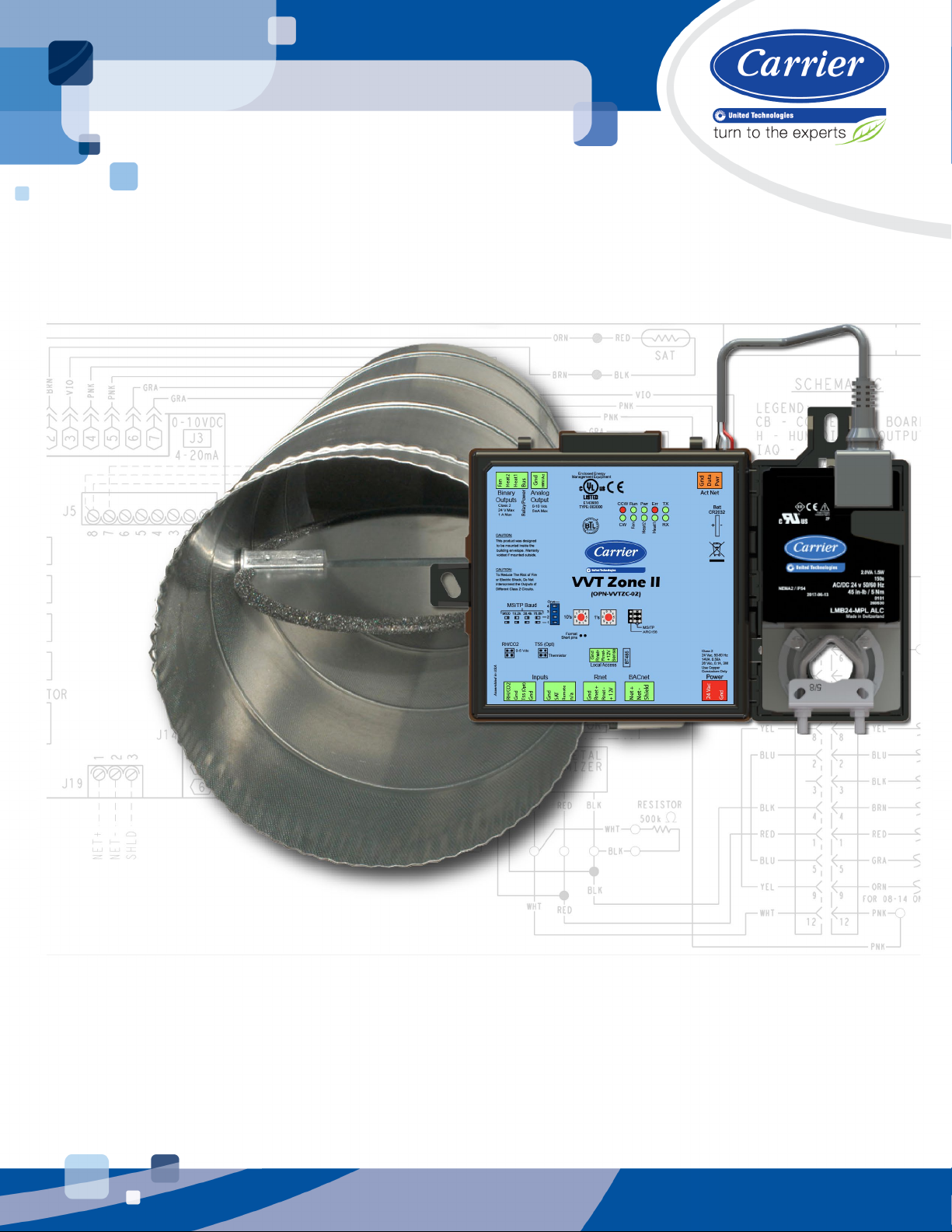
The VVT Zone II (#OPN-VVTZC-02), a component of the i-Vu® Control System, controls zone temperature in single
duct, fan powered, Variable Volume and Temperature (VVT
The VVT Zone II is available in both English or Metric units. The metric version has (-M) appended to the
part number. Everything in this document applies to both versions.
The VVT Zone II with actuator maintains zone temperature by operating the terminal fan and regulating the flow of
conditioned air into the space. Buildings with diverse loading conditions can be supported by controlling the air
source heating and cooling sources or supplemental heat. The VVT Zone II provides dedicated control functions for
single duct and fan box terminals with modulating heat, up to 3 stages of ducted heat, or combination baseboard
and ducted heat.
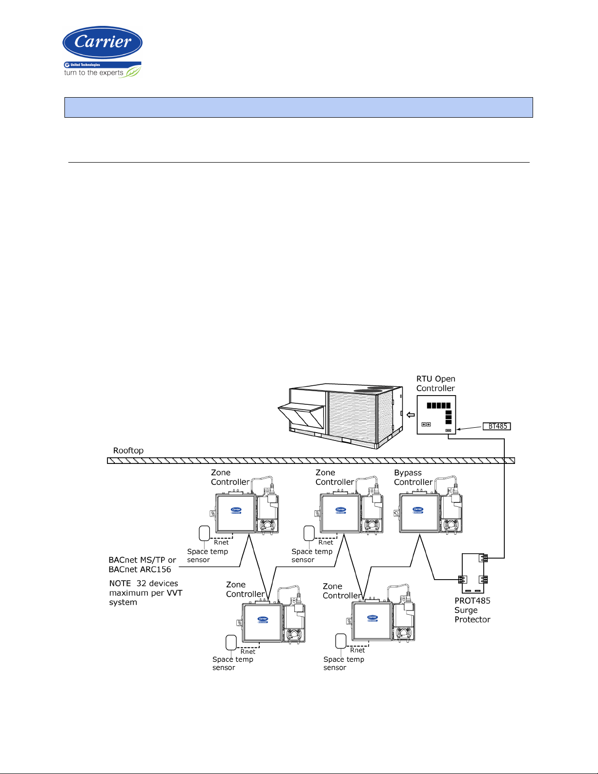
The i-Vu Control System uses linkage to exchange data between the zone terminals and their air source to form a
coordinated HVAC system. The system's air source controller, zone controllers, and bypass controller are linked so
that their data exchange can be managed by one zone controller configured as the VVT Master.
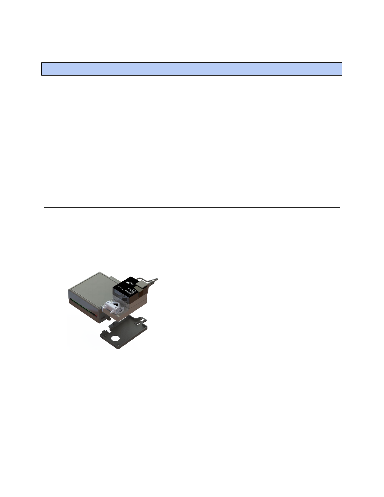
You can disconnect the actuator from the controller and mount them separately, connecting them with just the
actuator cable or using an additional extension cable, up to a maximum distance of 300 feet.
The following illustration shows the VVT Zone II in a typical i-Vu® Control System.
®
) applications.
VVT Zone II Controller CARRIER CORPORATION ©2019
Installation and Start-up Guide All rights reserved
1
Page 6
Introduction
NOTE
This document gives instructions for field-installation of a VVT Zone II in an i-Vu® Control System. However,
VVT Zone IIs are available factory-mounted to Carrier’s round and rectangular dampers. Damper assemblies have
an integrated duct temperature sensor.
VVT Zone II Controller CARRIER CORPORATION ©2019
Installation and Start-up Guide All rights reserved
2
Page 7

Introduction
Specifications
NOTE
Driver drv_vvtopn02
Power 24 Vac ±10%, 50–60 Hz
14 VA power consumption
26 Vdc (25 V min, 28.8 V max)
Single Class 2 source only, 100 VA or less
Actuator Belimo brushless DC motor, torque 45 inch-pounds (5 Nm), runtime 154 seconds
Act Net port To connect the actuator cable and the VVT Zone II
BACnet port
Rnet port
Local Access port For system start-up and troubleshooting using Field Assistant
For communication with the controller network using BACnet ARC156 (156 kbps)
or BACnet MS/TP (9600 bps – 76.8 kbps)
• Supports up to 5 wireless and/or ZS sensors, and one Equipment Touch or
TruVu™ ET Display.
• Supplies 12 Vdc/200 mA power to the Rnet at an ambient temperature of
77°F (25°C) with a 24 Vac nominal power source.
NOTE Ambient temperature and power source fluctuations may reduce the
power supplied by the Rnet port.
If the total power required by the sensors on the Rnet exceeds the power
supplied by the Rnet port, use an external power source. The Wireless Adapter,
Equipment Touch, or TruVu™ ET Display must be powered by an external power
source. See the specifications in each device's Installation and Start-up Guide to
determine the power required.
Thermistor inputs Accepts Precon type II thermistors (10kOhm at 77°F [25°C])
Range: -50°F (-45.5°C) to 250°F (121.1°C)
Dry contact inputs A 3.3 Vdc wetting voltage used to detect the contact position, resulting in a 0.3
mA maximum sense current when the contacts are closed.
Voltage inputs 0-5 Vdc. Input impedance is approximately 30 kOhms
Input resolution 10 bit A/D
Binary outputs 3 binary outputs, relay contact rated at 1 A max. @ 24 Vac/Vdc. Configured
normally open.
Analog output 1 analog output, 0–10 Vdc (5 mA max).
The controlled device must have a minimum of 2000 Ohms resistance measured
from its input to ground and must share the same ground as the controller.
Output resolution 8 bit D/A
Battery 10-year Lithium CR2032 battery retains the following data for a maximum of
10,000 hours during power outages: control programs, editable properties,
schedules, and trends.
VVT Zone II Controller CARRIER CORPORATION ©2019
Installation and Start-up Guide All rights reserved
3
Page 8

Introduction
CAUTION
Protection Built-in surge and transient protection for power and communications in
compliance with EN61000-6-1.
Incoming power and network connections are protected by non-replaceable
internal solid-state polyswitches that reset themselves when the condition that
causes a fault returns to normal.
The power, network, input, and output connections are also protected against
transient excess voltage/surge events lasting no more than 10 msec.
To protect against large electrical surges on serial EIA-485
networks, place a PROT485 at each place wire enters or exits the building.
BT485 connector You attach a BT485 (not included) to a controller at the beginning and end of a
network segment to add bias and to terminate a network segment.
Status indicators LEDs indicate status of communications, running, errors, power, and digital
outputs
Environmental operating
32 to 130°F (0 to 54.4°C), 10–90% relative humidity, non-condensing
range
Storage temperature range -24 to 140°F (-30 to 60°C), 0 to 90% relative humidity, non-condensing
Physical UL94-5VA plenum rated enclosure for installation in plenum (or other space for
environmental air) in accordance with NEC Section 300.22 (c) and (d)
Controller and actuator
overall dimensions
Controller and actuator
mounting dimensions
Controller overall
dimensions
Controller mounting
dimensions
Actuator overall dimensions Width:
Actuator mounting
Width:
Height:
8.9 in. (22.7 cm)
5.9 in. (15.0 cm)
7.1 in. (18.0 cm) from left side controller mounting hole centerline to actuator
mounting hole centerline
Width:
Height:
Depth:
6.4 in. (16.3 cm)
5.7 in. (14.5 cm)
2.1 in. (5.3 cm)
5.3 in. (13.4 cm) from left side controller mounting hole centerline to right side
controller mounting hole centerline
3.0 in. (7.6 cm)
Height:
Depth:
5.9 in. (15.0 cm)
2.5 in. (6.4 cm)
4.4 in. (11.2 cm) from shaft centerline to actuator mounting hole centerline
dimensions
Panel depth 2.5 in. (6.4 cm) minimum
Shaft dimensions Minimum shaft diameter: .25 in. (.64 cm)
Maximum shaft diameter: .63 in. (1.59 cm)
Minimum shaft length: 1.75 in. (4.45 cm)
Weight 1.8 lbs (0.82 kg)
BACnet support Conforms to the BACnet Advanced Application Controller (B-AAC) Standard Device
Profile as defined in ANSI/ASHRAE Standard 135-2012 (BACnet) Annex L,
Protocol Revision 9
Listed by UL-916 (PAZX), cUL-916 (PAZX7), FCC Part 15-Subpart B, Class B, CE
VVT Zone II Controller CARRIER CORPORATION ©2019
Installation and Start-up Guide All rights reserved
4
Page 9
Introduction
Safety Considerations
CAUTION
WARNING Electrical Shock Hazard
WARNING
Field-supplied hardware
Air conditioning equipment will provide safe and reliable service when operated within design specifications. The
equipment should be operated and serviced only by authorized personnel who have a thorough knowledge of
system operation, safety devices, and emergency procedures.
Good judgment should be used in applying any manufacturer's instructions to avoid injury to personnel or damage
to equipment and property.
Failure to follow this warning could cause personal injury, death, and/or equipment damage.
Disconnect all power to the unit before performing maintenance or service. Unit may automatically start if power is
not disconnected.
materials such as mercury contactors.
Follow all local, state, and federal laws regarding disposal of equipment containing hazardous
Each zone controller installation requires the following field-supplied components:
• zone terminal unit
• round or rectangular mounting bracket
• space temperature sensor
• supply air temperature sensor
• 2x4 in. standard single gang electrical box
• transformer — 24 Vac, 40 VA
• two no. 10 x 1/2-in. sheet metal screws (to secure SAT sensor to duct)
• two no. 6-32 x 5/8-in. screws (to mount space temperature sensor base to electrical box)
• wiring
• bushings (required when mounting SAT sensor in a duct 6-in. (15.2 cm) or less in diameter)
Optional:
• contractors (if required for fan or electric heat)
• indoor air quality sensor
• relative humidity sensor
• 2 screws and 2 hollow wall anchors (to mount relative humidity sensor directly to wall)
• valve and actuator for hot water heat (if required)
VVT Zone II Controller CARRIER CORPORATION ©2019
Installation and Start-up Guide All rights reserved
5
Page 10
Installing the VVT Zone II
Mounting the VVT Zone II
To mount the controller and actuator
Installing the VVT Zone II
To install the VVT Zone II:
1 Mount the controller to the VVT box. (page 6)
2 Wire the controller for power. (page 10)
3 Set the controller's address. (page 12)
4 Wire the controller to the BACnet MS/TP or BACnet ARC156 network. (page 12)
5 Wire devices to the Rnet port. (page 13)
6 Wire sensor(s) to the controller. (page 19)
7 Wire equipment to the controller's outputs. (page 25)
To disconnect and mount the controller and actuator separately
VVT Zone II Controller CARRIER CORPORATION ©2019
Installation and Start-up Guide All rights reserved
6
Page 11
Installing the VVT Zone II
Act Net
Adding an extension cable
Act Net
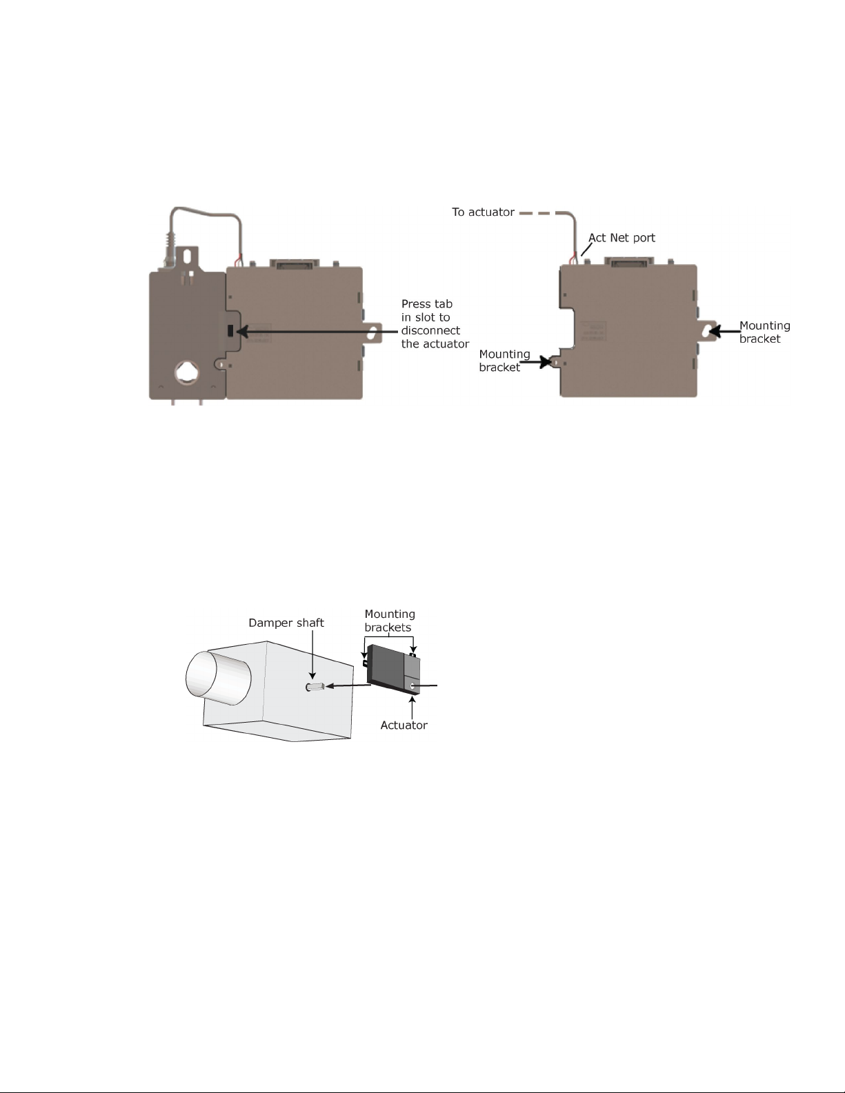
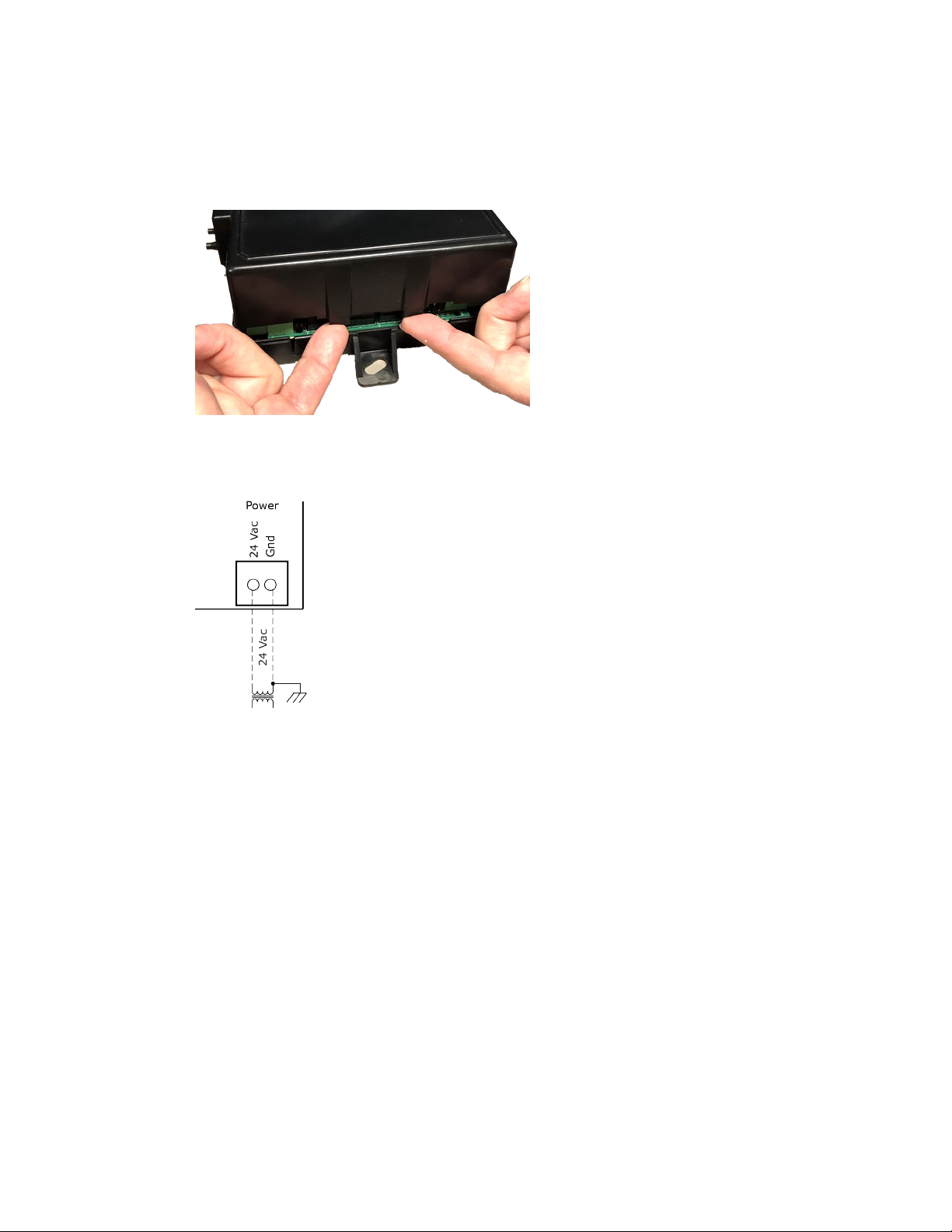
Disconnect the actuator from the controller by inserting a screw driver in the slot on the back of the VVT Zone II
and pressing the tab. The actuator cable or an attached extension cable must connect to the controller's
port.
If you need to mount the actuator more than 14 in. from the controller, you can use an 18 AWG wire for an
extension cable. The maximum distance that the actuator and controller can be separated is 300 feet (91.4 m).
Connect the extension cable to the end of the actuator cable. You can use connectors or splice the wires.
Terminate the extension cable in the
1 Turn the damper shaft to fully close the damper.
2 Mount the controller to the VVT terminal by sliding the clamp assembly onto the damper shaft.
port on the controller.
VVT Zone II Controller CARRIER CORPORATION ©2019
Installation and Start-up Guide All rights reserved
7
Page 12
Installing the VVT Zone II
NOTE
O-ring Bushing
Anti-rotation slot
NOTES
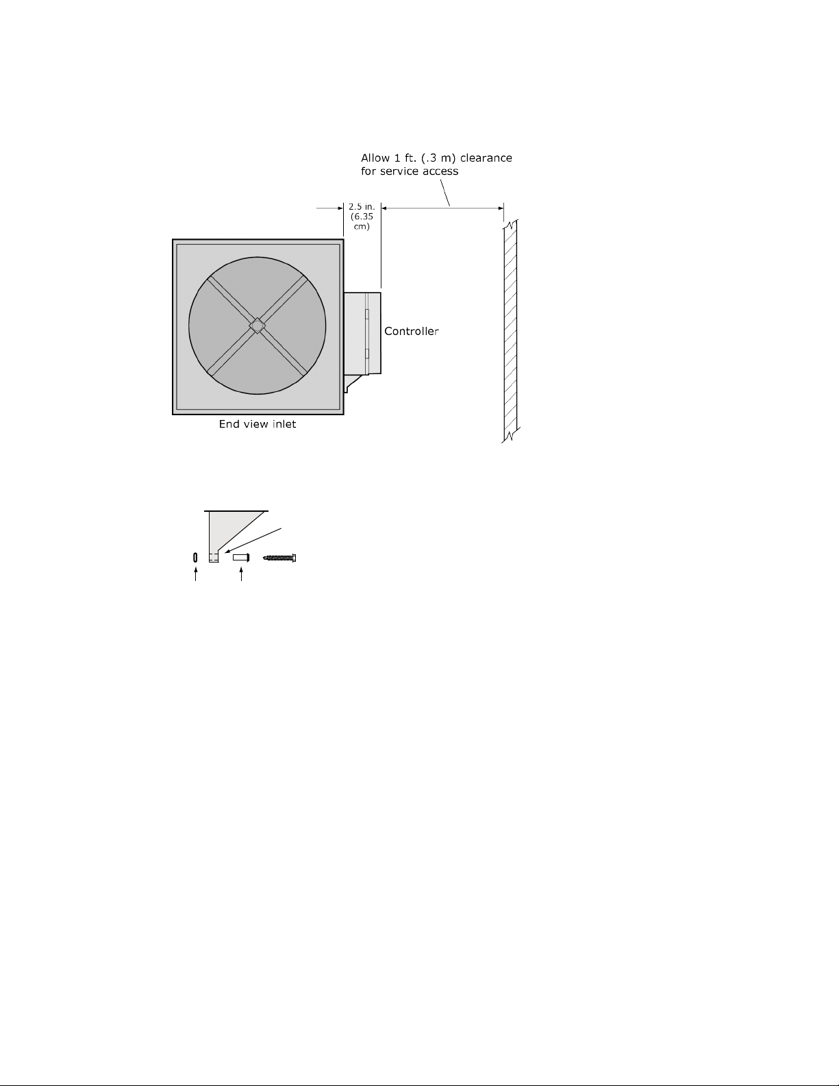
For service access, allow at least 1 foot (.3 m) of clearance between the front of the controller and
adjacent surfaces.
3 Secure the controller and the actuator by installing the screws, anti-rotation slot's bushings, and o-rings that
are supplied with the VVT Zone II.
○ Center the bushing in the slot. Failure to do so may cause the actuator to stick or bind.
○ The VVT Zone II must be secured, but loose enough to allow movement. of the damper shaft.
VVT Zone II Controller CARRIER CORPORATION ©2019
Installation and Start-up Guide All rights reserved
8
Page 13
Installing the VVT Zone II
CAUTIONS
must
○ You
○ Overtightening the screws so that the controller and actuator cannot move may damage the unit.
use the screws, anti-rotation slot's bushings, and o-rings that are shipped with the VVT Zone II.
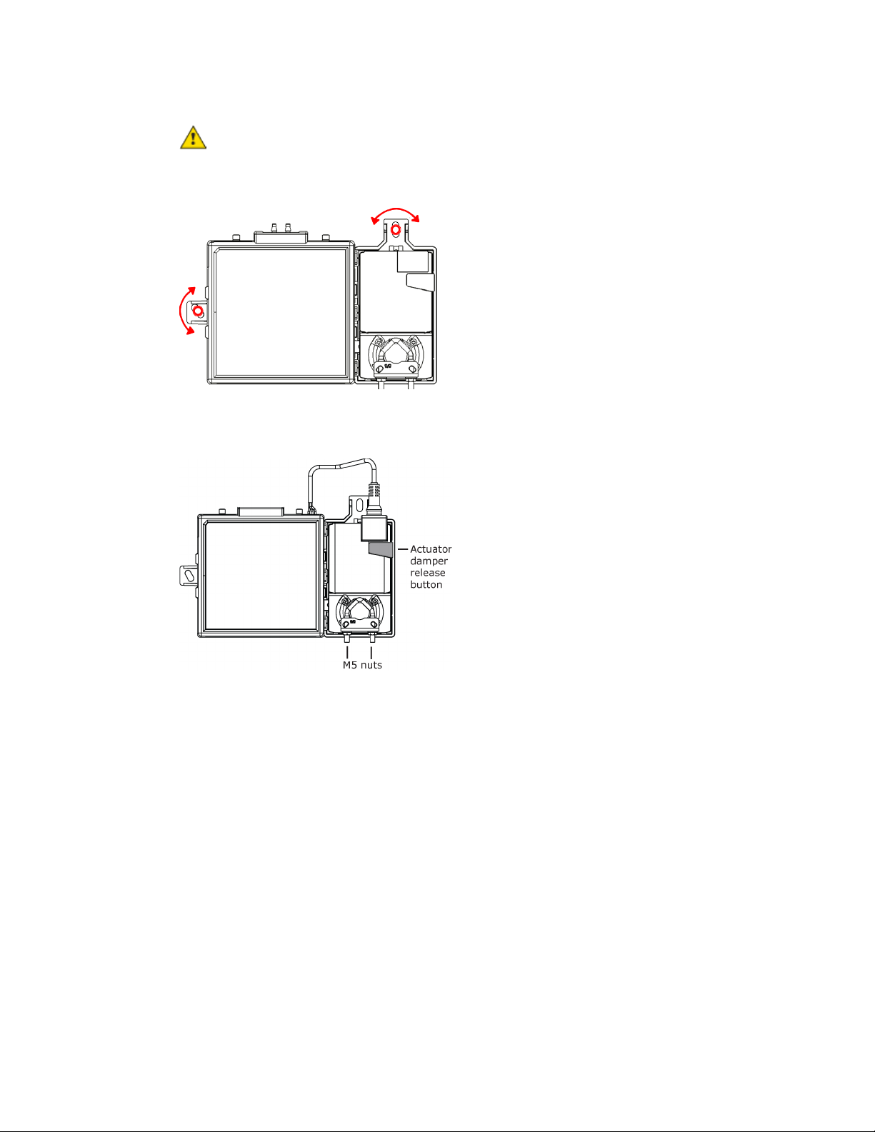
4 Hold down the actuator damper release button and rotate the actuator clamp in the same direction that
closed the damper. Rotate the clamp until it stops, then rotate it back one notch.
5 Release the button.
6 Tighten the actuator clamp to the damper shaft by tightening the two M5 nuts.
VVT Zone II Controller CARRIER CORPORATION ©2019
Installation and Start-up Guide All rights reserved
9
Page 14

Installing the VVT Zone II
Wiring the VVT Zone II for power
WARNING
CAUTIONS
7 Hold down the actuator damper release button and rotate the damper from fully closed to fully open. If the
damper traveled less than 90 degrees, do the following to set the actuator's fully open position:
a) Loosen the appropriate stop clamp screw. See figure below.
b) Move the stop clamp until it contacts the
edge of the actuator cam.
c) Tighten the screw.
8 Hold down the actuator damper release button, rotate the damper to verify that it fully opens and closes, then
release the button.
• The VVT Zone II is powered by a Class 2 power source. Take appropriate isolation measures when mounting it
in a control panel where non-Class 2 circuits are present.
• Carrier controllers can share a power supply as long as you:
• Maintain the same polarity.
• Use the power supply only for Carrier controllers.
Do not apply line voltage (mains voltage) to the controller's ports and terminals.
VVT Zone II Controller CARRIER CORPORATION ©2019
Installation and Start-up Guide All rights reserved
10
Page 15
Installing the VVT Zone II
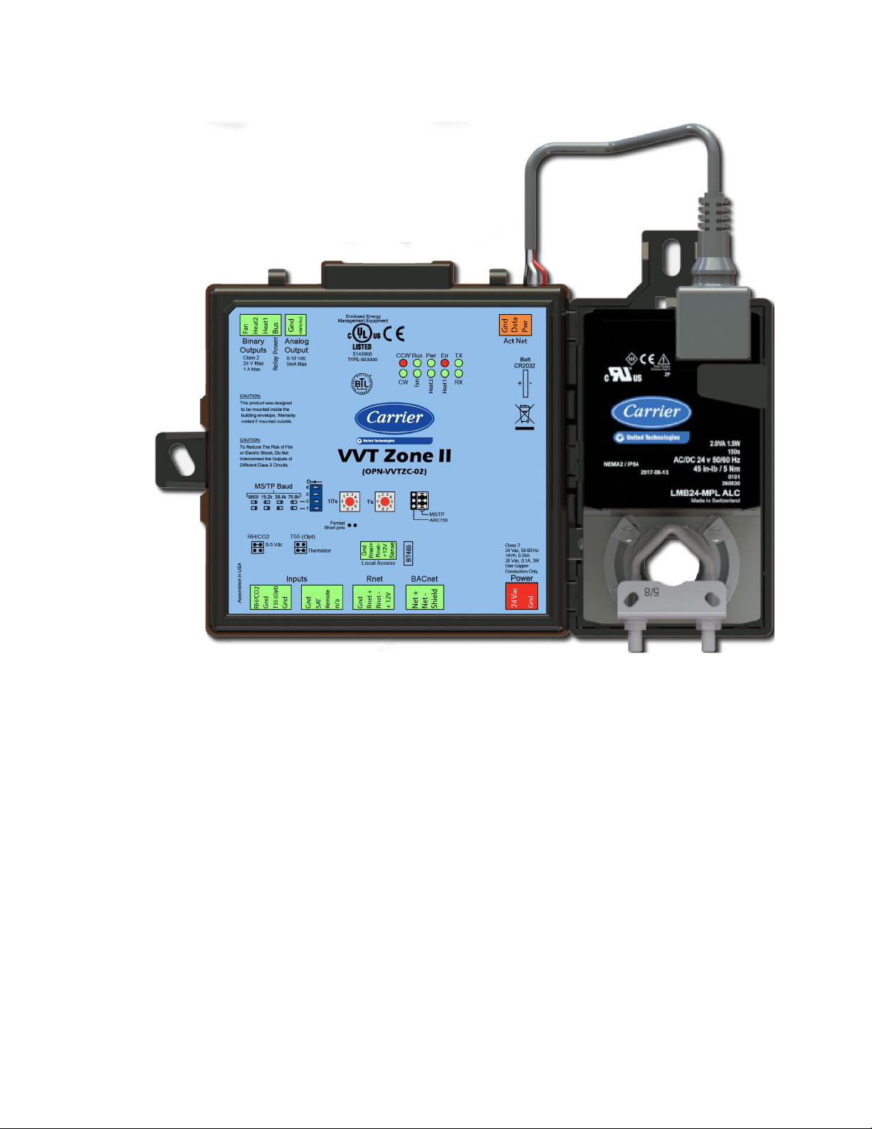
To wire the controller for power
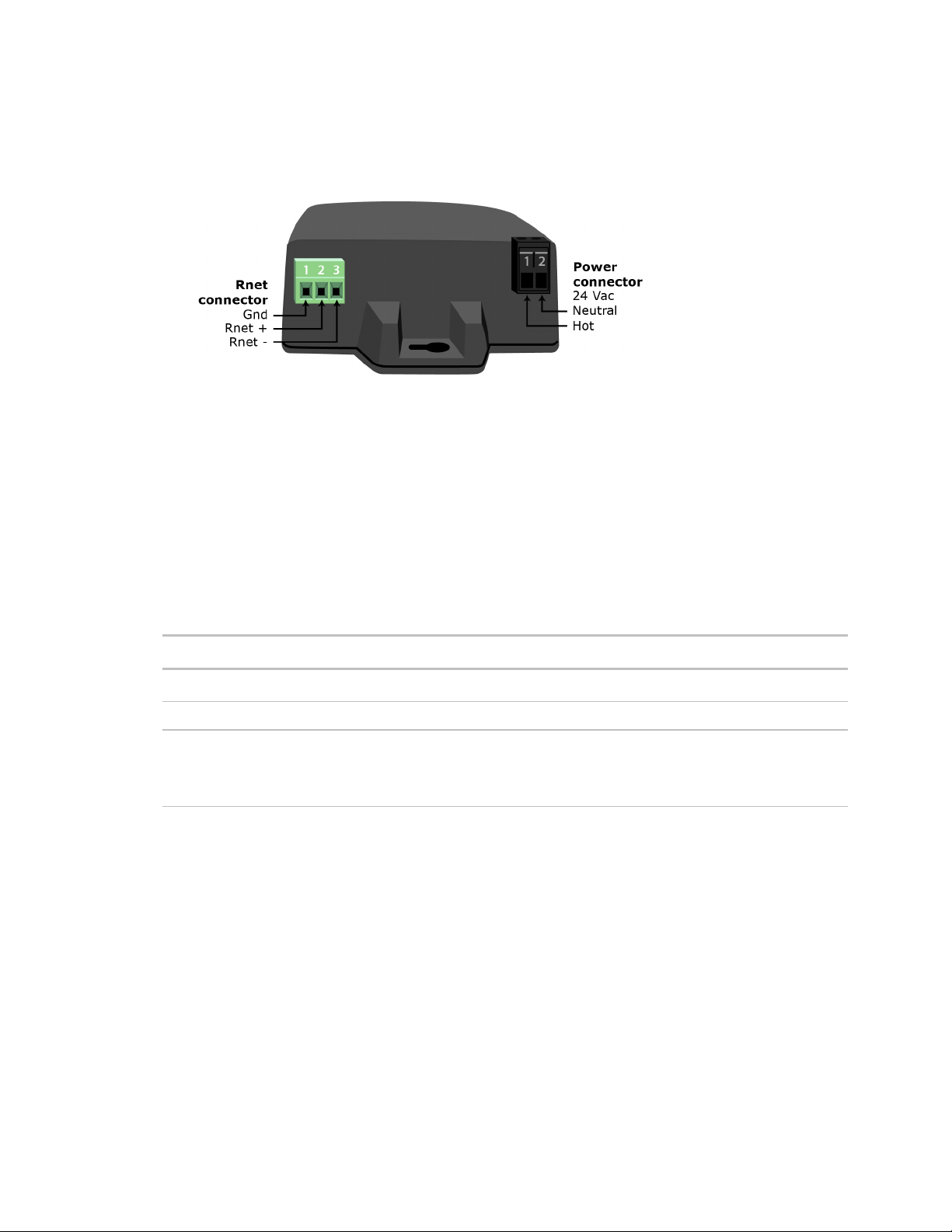
Gnd
24 Vac
Gnd
Power
Run
1 To access the screw terminal connectors, lift up the controller's cover by pulling the tabs located on both
sides of the controller's left mounting bracket.
2 Remove power from the power supply.
3 Pull the screw terminal connector from the controller's power terminals labeled
and
.
4 Connect the transformer wires to the screw terminal connector.
5 Apply power to the power supply.
6 Measure the voltage at the VVT Zone II’s power input terminals to verify that the voltage is within the
operating range of 21.6–26.4 Vac.
7 Connect a 4-inch (10.2 cm) wire from
to the control panel.
8 Insert the screw terminal connector into the VVT Zone II's power terminals.
9 Verify that the
LED is on and the
LED is blinking.
VVT Zone II Controller CARRIER CORPORATION ©2019
Installation and Start-up Guide All rights reserved
11
Page 16
Installing the VVT Zone II
Addressing the VVT Zone II
Gnd
24 Vac
Tens (10's
Ones (1's
EXAMPLE
Tens (10's
Ones (1's
10's 1's
1
3
4
5
2
7
8
9
6
0
1
3
4
5
2
7
8
9
6
0
CAUTION
Wiring for communications
NOTE
Wiring specifications for BACnet MS/TP and ARC156
WARNING
You must give the VVT Zone II an address that is unique on the network. You can address the VVT Zone II before or
after you wire it for power.
1 If the VVT Zone II has been wired for power, pull the screw terminal connector from the controller's power
terminals labeled
2 Using the rotary switches, set the controller's address. Set the
address, and set the
the
If the controller’s address is 25, point the arrow on the
and
) switch to 5.
. The controller reads the address each time you apply power to it.
) switch to the tens digit of the
) switch to the ones digit.
) switch to 2 and the arrow on
The factory default setting is 00 and must be changed to successfully install your VVT Zone II.
The VVT Zone II communicates using BACnet on the following types of network segments:
• MS/TP communicating at 9600 bps, 19.2 kbps, 38.4 kbps, or 76.8 kbps
• ARC156 communicating at 156 kbps
For more networking details, see the Open Controller Network Wiring Installation Guide.
Cable: 22 AWG or 24 AWG, low-capacitance, twisted, stranded, shielded copper wire
Maximum length: 2000 feet (610 meters)
Do not apply line voltage (mains voltage) to the controller's ports and terminals.
VVT Zone II Controller CARRIER CORPORATION ©2019
Installation and Start-up Guide All rights reserved
12
Page 17

Installing the VVT Zone II
To wire the controller to the BACnet network
WARNING
Act Net
Gnd
24 Vac
Net +, Net -
Shield
NOTE
For...
Set BACnet ARC156 or MS/TP
jumper to...
Set DIP switches 1 and 2 to...
ARC156
MS/TP
MS/TP Baud
NOTE
Wiring devices to the VVT Zone II's Rnet port
CAUTION Rnet power
terminating resistors on that network.
1 Pull the screw terminal connector from the controller's power terminals labeled
2 Check the communications wiring for shorts and grounds.
3 Connect the communications wiring to the controller’s screw terminals labeled
4 Set the communication type and baud rate.
Attaching any ARCNET or MS/TP network to the
Use the same polarity throughout the network segment.
port damages BT485s, DIAG485s, or
and
.
, and
.
ARC156
N/A. Baud rate will be 156 kbps regardless of the
DIP switch settings.
MS/TP
The appropriate baud rate. See the
diagram on the controller.
Use the same baud rate for all controllers on the network segment.
5 If the VVT Zone II is at either end of a network segment, connect a BT485 to the VVT Zone II.
6 Insert the power screw terminal connector into the VVT Zone II's power terminals.
7 Verify communication with the network by viewing a Module Status report in the i-Vu® interface.
The Rnet communicates at a rate of 115 kbps and should be wired in a daisy-chain or hybrid configuration.
Supports up to
• 5 wireless and/or ZS sensors
• One Equipment Touch
• One TruVu™ ET Display
For more detailed instructions, see the device's Installation Guide.
The Rnet port provides 12 Vdc/200 mA* maximum at 32°F (25°C). that can be used to power zone sensors. If
the total power required by the sensors on the Rnet exceeds the power supplied by the port, use an external
power supply. See the sensor's Installation and Start-up Guide to determine the power required.
* These numbers will be reduced at higher temperatures.
VVT Zone II Controller CARRIER CORPORATION ©2019
Installation and Start-up Guide All rights reserved
13
Page 18
Installing the VVT Zone II
Wiring specifications
To wire ZS sensors to the controller
NOTE
Outer Jack
et
Inner insulation
.25 in.
(.6 cm)
NOTE
Connect this wire...
To this terminal...
Cable from sensor to controller: If <100 ft (30.5 meters) 22 AWG, unshielded
If >100 ft (30.5 meters) 22 AWG, shielded
Maximum length: 500 feet (152 meters)
ZS Sensors are thermistor-based temperature sensors that may optionally sense humidity, CO2, or VOC. ZS
Sensors are wired to the Rnet port on i-Vu® Open controllers.
You can use the following ZS sensors:
• ZS Standard
• ZS Plus
• ZS Pro
The ZS CO2 model uses 190 mA during sample period. Use auxiliary 12 Vdc, unless it is the only device on
the Rnet port.
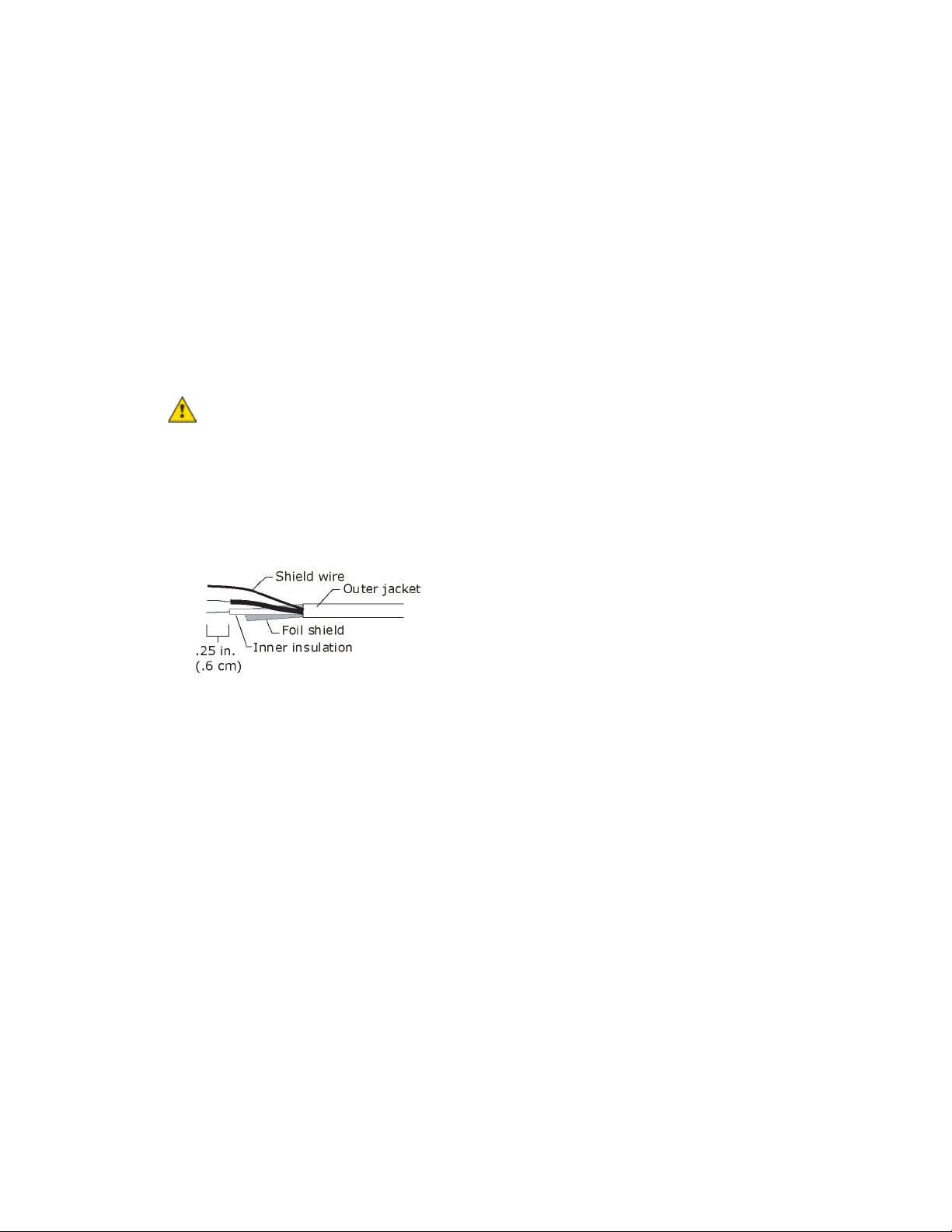
1 Remove power from the VVT Zone II.
2 Partially cut, then bend and pull off the outer jacket of the Rnet cable(s). Do not nick the inner insulation.
Strip about .25 inch (.6 cm) of the inner insulation from each wire.
3 Wire each terminal on the sensor to the same terminal on the controller. See diagram below.
Carrier recommends that you use the following Rnet wiring scheme:
Red
Black
White
Green
+12V
Rnet-
Rnet+
Gnd
4 Apply power to the VVT Zone II.
VVT Zone II Controller CARRIER CORPORATION ©2019
Installation and Start-up Guide All rights reserved
14
Page 19
Installing the VVT Zone II
To wire the Wireless Adapter for wireless sensors
WARNING
REQUIREMENTS
NOTES
Inner insulation
Outer jacket
Foil shield
.25 in.
(.6 cm)
Shield wire
The Carrier wireless sensors are available in 868, 902, and 928 MHz radio frequency. The sensors are thermistorbased temperature sensors that may optionally sense humidity.
Wireless sensors communicate through a Wireless Adapter, which is wired to the Rnet port of the controller.
• A v6.5 or later i-Vu® system
• v6-xx-xxx or later controller drivers
To configure the control program for the desired user interaction with the sensor, see the Wireless Sensors
Application Guide. For detailed instructions, see the Wireless Sensors Installation Guide.
To wire, power, and mount the Wireless Adapter
• The Wireless Adapter requires a 24 Vac power supply. It is not powered by the Rnet.
Do not apply line voltage (mains voltage) to the Wireless Adapter.
• If the Wireless Adapter will be:
○ Daisy-chained on the Rnet with ZS sensors, an Equipment Touch, or TruVu™ ET Displayuse the standard
4-conductor Rnet wiring.
○ The only device on the Rnet, you can use a 3-conductor cable instead of the standard 4-conductor Rnet
cable.
1 Turn off the power to the controller that the Wireless Adapter will be wired to.
2 Partially cut, then bend and pull off the outer jacket of the Rnet cable(s). Do not nick the inner insulation.
3 Strip about 0.25 inch (0.6 cm) of the inner insulation from each wire.
VVT Zone II Controller CARRIER CORPORATION ©2019
Installation and Start-up Guide All rights reserved
15
Page 20
Installing the VVT Zone II
Rnet +, Rnet -
Gnd
Rnet
NOTE
Gnd
LED
If the LED is...
Then the device...
device.
4 Wire the
, and
terminals on the controller's
port to the terminals of the same name on
the Wireless Adapter's Rnet connector.
If using shielded wire, connect the shield wire and the ground wire to the
terminal.
5 Wire the 24 Vac external power supply to the Wireless Adapter's power connector.
6 Mount the Wireless Adapter by inserting 2 screws through the mounting tabs on each end of the Wireless
Adapter.
7 Apply power to the external power supply.
8 Verify that the LED on top of the Wireless Adapter is blinking. See "LED" below.
9 Turn on the controller's power.
The blue LED on the top of the Wireless Adapter indicates the following:
Off Is not powered or there is a problem.
Blinking Is working properly.
Steadily on Has a problem. Do one of the following:
• Cycle power to the device.
• Insert a small screwdriver or paper clip into the hole next to the LED to reboot the
VVT Zone II Controller CARRIER CORPORATION ©2019
Installation and Start-up Guide All rights reserved
16
Page 21
Installing the VVT Zone II
To wire an Equipment Touch to the VVT Zone II
NOTES
CAUTION
off
Rnet+
Rnet-
NOTE
Gnd
• The Equipment Touch requires a 24 Vac power supply. It is not powered by the Rnet.
• If the Equipment Touch will be:
○ Daisy-chained on the Rnet with ZS sensors or a Wireless Adapter, use the standard 4-conductor Rnet
wiring and follow the wiring instructions To wire ZS sensors to the VVT Zone II (page 14).
○ The only device on the Rnet, you can use a 2-conductor cable instead of the standard 4-conductor Rnet
cable and follow the instructions below.
• For complete Equipment Touch installation instructions including wiring diagrams, see the Equipment Touch
Installation and Setup Guide.
• The power supply is AC power.
• You maintain the same polarity.
• You use the power source only for Carrier controllers.
1 Turn
2 Partially cut, then bend and pull off the outer jacket of the cable. Do not nick the inner insulation.
The VVT Zone II can share a power supply with the Carrier controller as long as:
the VVT Zone II's power.
3 Strip about 0.25 inch (0.6 cm) of the inner insulation from each wire.
4 Wire the VVT Zone II's
and
terminals to the terminals of the same name on the Equipment
Touch's connector.
If using shielded wire, connect the shield wire and the ground wire to the
terminal.
5 Turn on the VVT Zone II's power.
6 Turn on the Equipment Touch.
VVT Zone II Controller CARRIER CORPORATION ©2019
Installation and Start-up Guide All rights reserved
17
Page 22
Installing the VVT Zone II
To wire the TruVu™ ET Display
WARNING
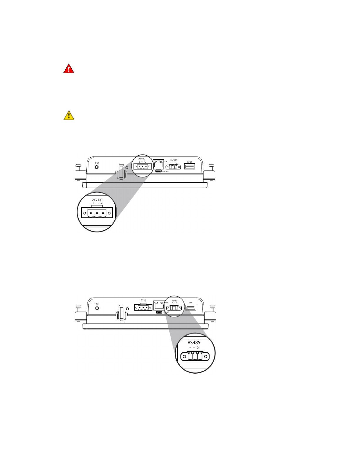
24V DC
CAUTION
RS485
Rnet
Gnd
Gnd, +
Rnet +, -
Rnet -
Wiring power
Do not apply line voltage (main) - 24 Vdc power only.
Wire the TruVu™ ET Display
Maximum distance 100 feet (30 meters).
• The power supply is DC power.
• You maintain the same polarity.
• You use the power source only for Carrier controllers.
The TruVu™ ET Display can share a power supply with the Carrier controller as long as:
connector to the 24 Vdc power supply using 2-conductor 18 AWG wire.
Wiring communication
1 Turn off the VVT Zone II's power.
2 Wire the TruVu™ ET Display's
using 2-conductor 22 AWG wire with a maximum distance of 500 feet (152 meters).
connector to the <ALCProduct>'s
port,
to
to
to
3 Turn on the VVT Zone II's power.
For complete TruVu™ ET Display installation instructions, see the TruVu™ ET Display Installation and Start-up
Guide.
VVT Zone II Controller CARRIER CORPORATION ©2019
Installation and Start-up Guide All rights reserved
18
Page 23

Installing the VVT Zone II
Wiring sensors to the VVT Zone II's inputs
NOTE
WARNING
CAUTION
Wiring specifications
You can wire the following sensors to the VVT Zone II's inputs:
• Alternate space temperature sensor (page 20)
• Supply Air Temperature sensor (page 20)
• Duct Air Temperature sensor (page 21)
• CO
sensor (page 21)
2
• Relative Humidity sensor (page 23)
• Remote occupancy contact sensor (page 24)
This document gives instructions for wiring the sensors to the VVT Zone II. For detailed installation
instructions, see the device's Installation Guide.
Disconnect electrical power to the VVT Zone II before wiring it. Failure to follow this warning could
cause electrical shock, personal injury, or damage to the controller.
• Do not run sensor or relay wires in the same conduit or raceway with Class 1 AC or DC service wiring.
• Do not abrade, cut, or nick the outer jacket of the cable.
• Do not pull or draw cable with a force that may harm the physical or electrical properties.
• Avoid splices in any control wiring.
Cable from sensor to controller: If <100 ft (30.5 meters) 22 AWG, unshielded
If >100 ft (30.5 meters) 22 AWG, shielded
Maximum length: 500 feet (152 meters)
VVT Zone II Controller CARRIER CORPORATION ©2019
Installation and Start-up Guide All rights reserved
19
Page 24
Installing the VVT Zone II
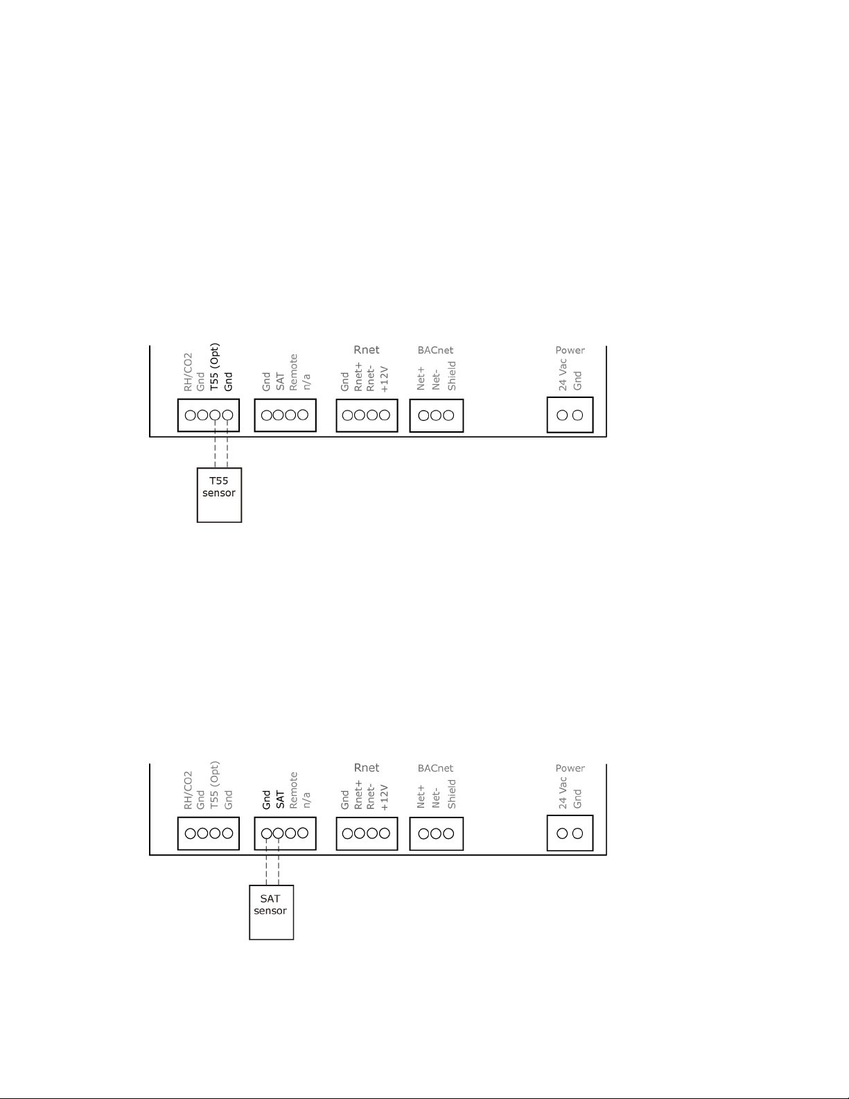
To wire the T55 sensor to the controller
T55 (Opt)
Gnd
T55 (Opt)
Thermistor
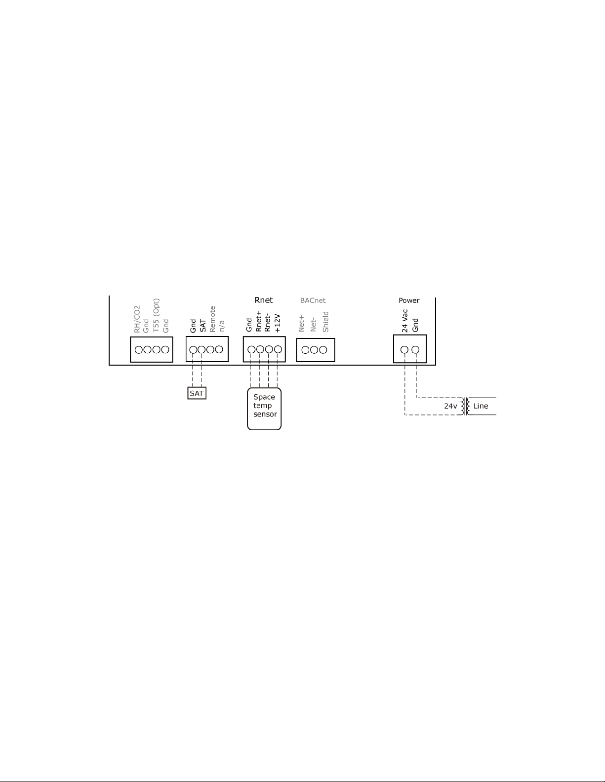
To wire the Supply Air Temperature sensor to the controller
Part #33ZCT55SPT
This wall-mounted sensor monitors space temperature and can be used instead of a ZS or wireless sensors.
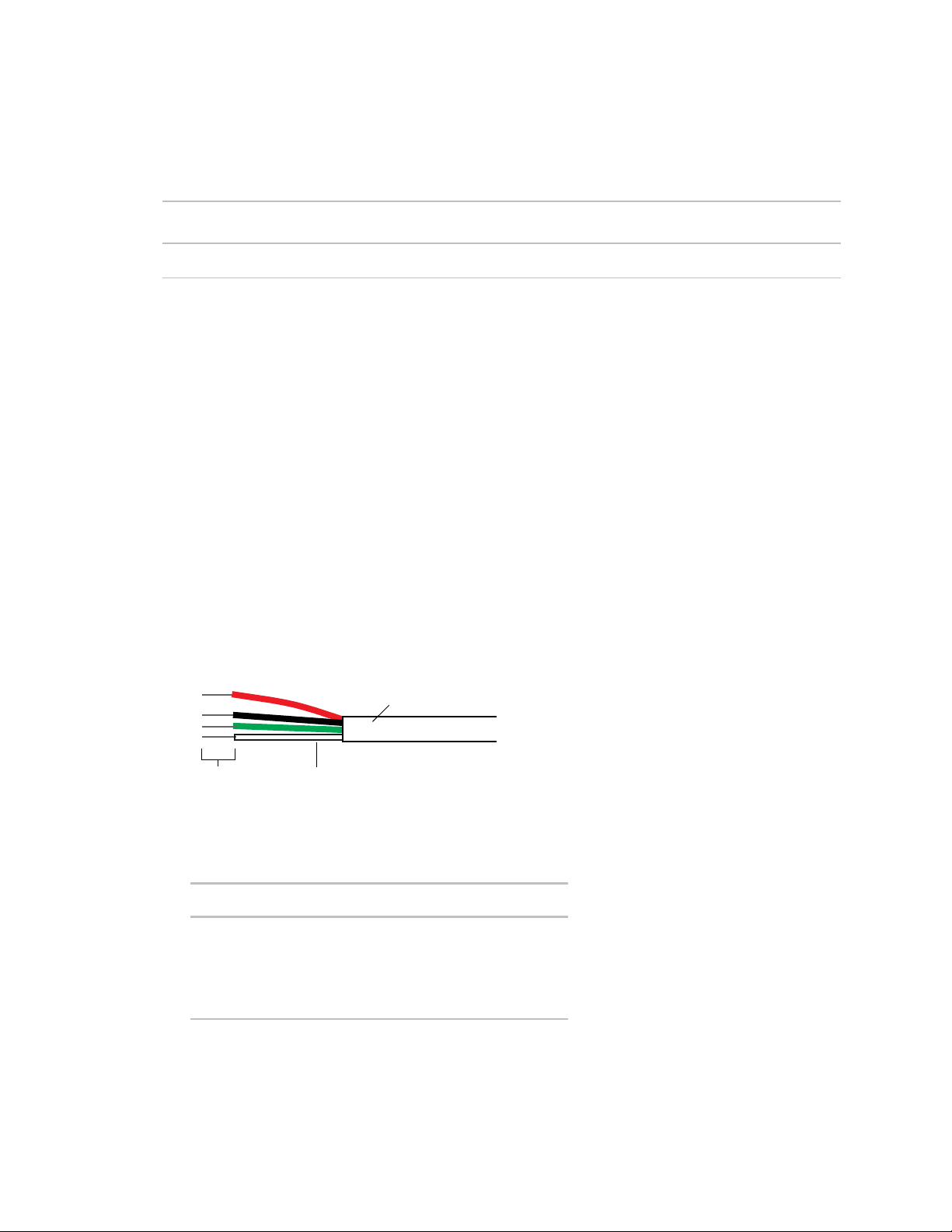
1 Strip the outer jacket from the cable for at least 3 inches (7.62 cm). Strip .25 inch (.6 cm) of insulation from
each wire. Cut the shield and drain wire from the cable.
2 Wire the sensor to the controller, attaching the red wire to the
terminal. See diagram below.
3 Verify that the
jumper is in the
position.
terminal and the black wire to the
Part #33ZCSENSAT
Each VVT Zone II requires that a temperature sensor be installed in the supply air stream. Mount the SAT sensor
at least 2 feet downstream from a hot water or steam coil, or at least 4 feet downstream from an electric heating
coil.
Wire the sensor to the controller. See diagram below.
VVT Zone II Controller CARRIER CORPORATION ©2019
Installation and Start-up Guide All rights reserved
20
Page 25
Installing the VVT Zone II
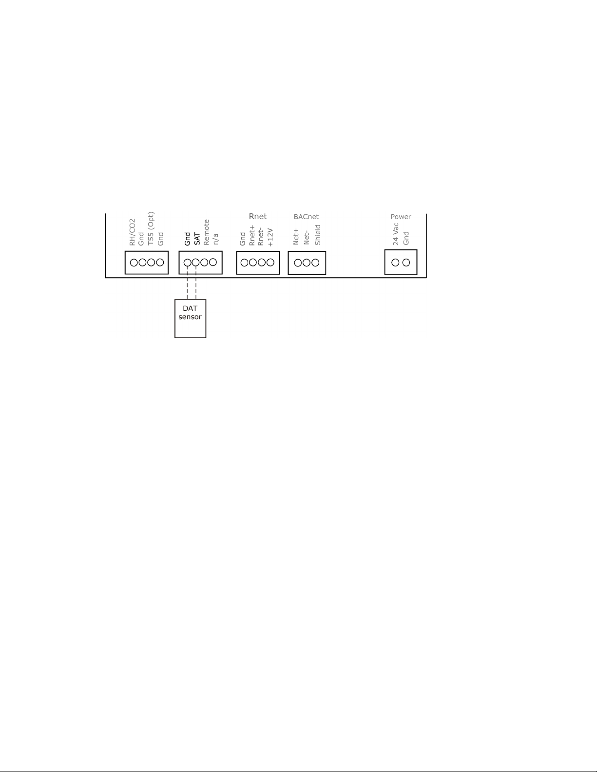
To wire a Duct Air Sensor to the controller
NOTE
Enable SAT
Enable SAT and REMOTE
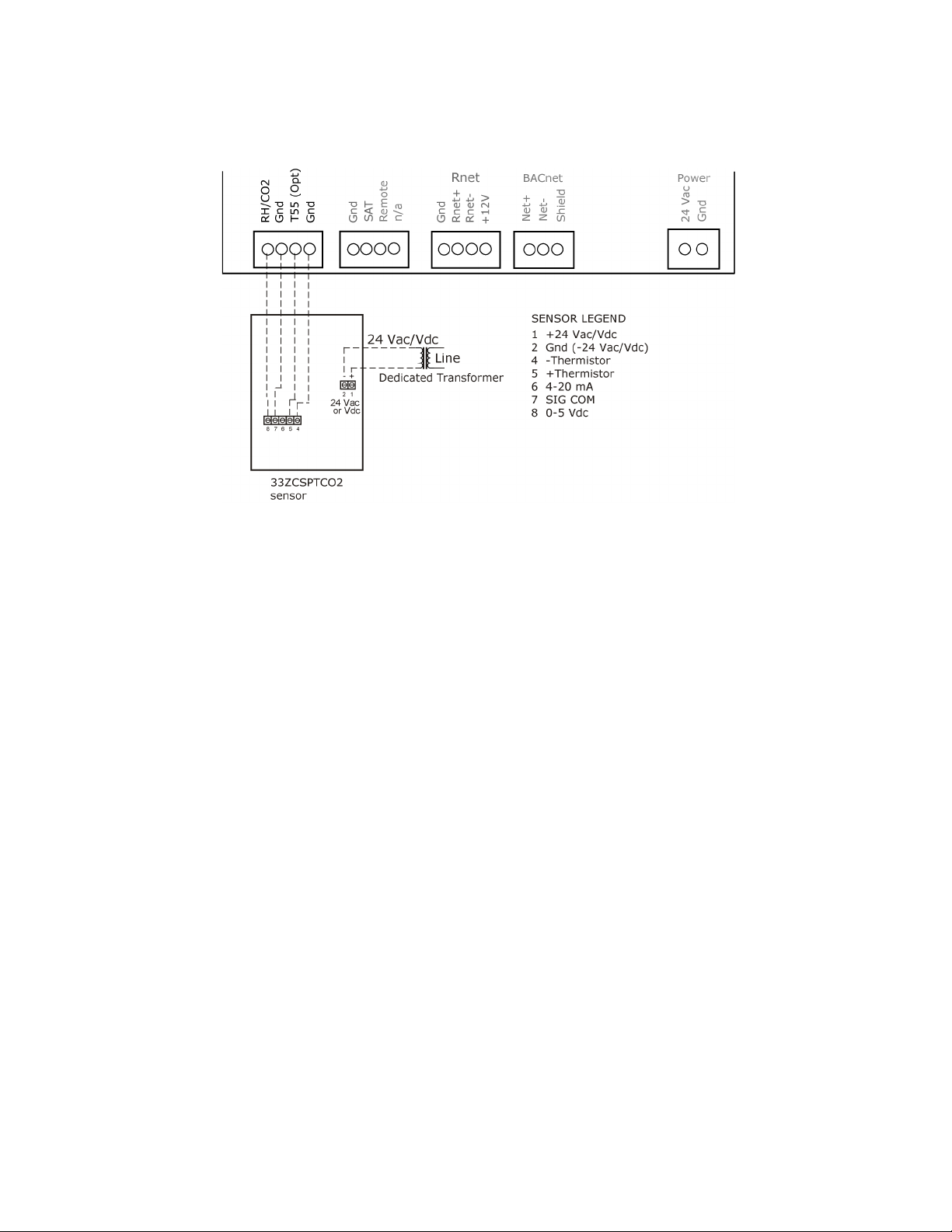
To wire the CO2 sensor to the controller
NOTE
#33ZCSPTCO2
RH/CO2
0-5 Vdc
0-5 Vdc
1 Wire the sensor to the controller. See diagram below.
Sensor wiring does not have polarity. The wires can be connected to either terminal.
2 Using electrical tape, insulate any exposed wire to prevent shorting.
3 Connect shield to earth ground (if using shielded wire to extend cable length).
4 Verify that the
5 Verify that the
jumper is on.
jumper is in the left position.
Part #33ZCSPTCO2LCD-01 (Display model)
Part #33ZCSPTCO2-01 (No display)
Part #33ZCT55CO2 (No display)
A CO
sensor monitors carbon dioxide levels. As CO2 levels increase, the VVT Zone II adjusts the outside air
2
dampers to increase ventilation and improve indoor air quality. These sensors also monitor temperature using a
10K thermistor.
A CO
sensor can be wall-mounted or mounted in a return air duct. (Duct installation requires an Aspirator Box
2
Accessory - Part #33ZCASPCO2.)
The sensor has a range of 0–2000 ppm and a linear 4-20 mA output. This is converted to 1-5 Vdc by a 250 Ohm,
1/4 watt, 2% tolerance resistor connected across the zone controller's CO2 input terminals.
Do not use a relative humidity sensor and CO2 sensor on the same zone controller.
1 Wire the sensor to the controller. See appropriate diagram below.
2 Verify that the
3 Verify the J7 jumper on the sensor is set to
jumper is set to
on the VVT Zone II.
.
VVT Zone II Controller CARRIER CORPORATION ©2019
Installation and Start-up Guide All rights reserved
21
Page 26
Installing the VVT Zone II
Wiring diagram for #33ZCSPTCO2:
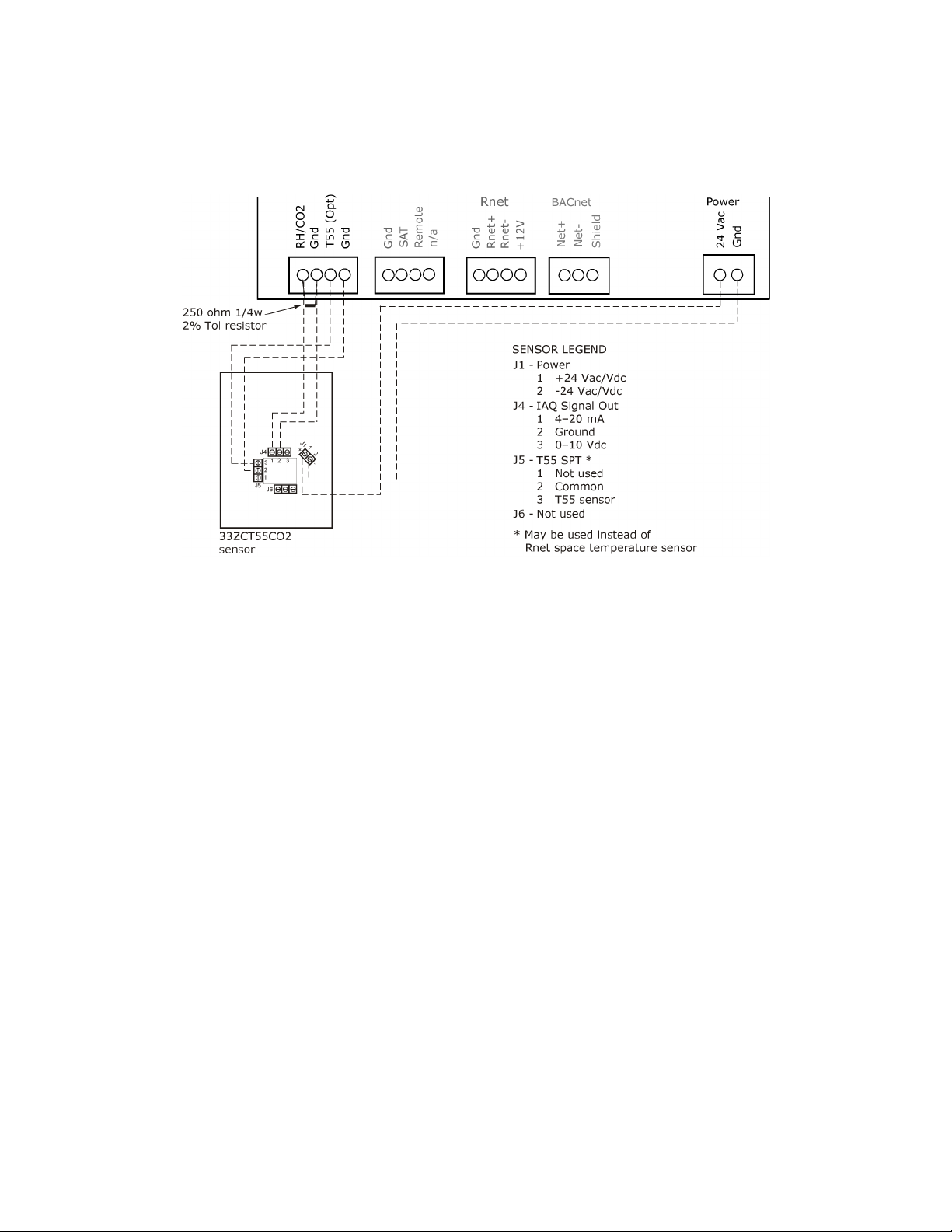
#33ZCT55CO2
RH/CO2
Gnd
RH/CO2
0-5Vdc
1 Wire the sensor to the controller. See appropriate diagram below.
2 Install a field supplied 250 Ohm 1/4 watt 2% tolerance resistor across the controller's
terminals.
3 Verify that the
jumper is set to
on the VVT Zone II.
and
VVT Zone II Controller CARRIER CORPORATION ©2019
Installation and Start-up Guide All rights reserved
22
Page 27
Installing the VVT Zone II
Wiring diagram for #33ZCT55CO2:
To wire the Relative Humidity sensor to the controller
NOTE
RH/CO2
0-5 Vdc
Part #33ZCSENSRH-02
The Relative Humidity (RH) sensor is used for zone humidity control (dehumidification) if the rooftop unit has a
dehumidification device. If not, the sensor only monitors humidity.
Do not use a relative humidity sensor and CO2 sensor on the same zone controller.
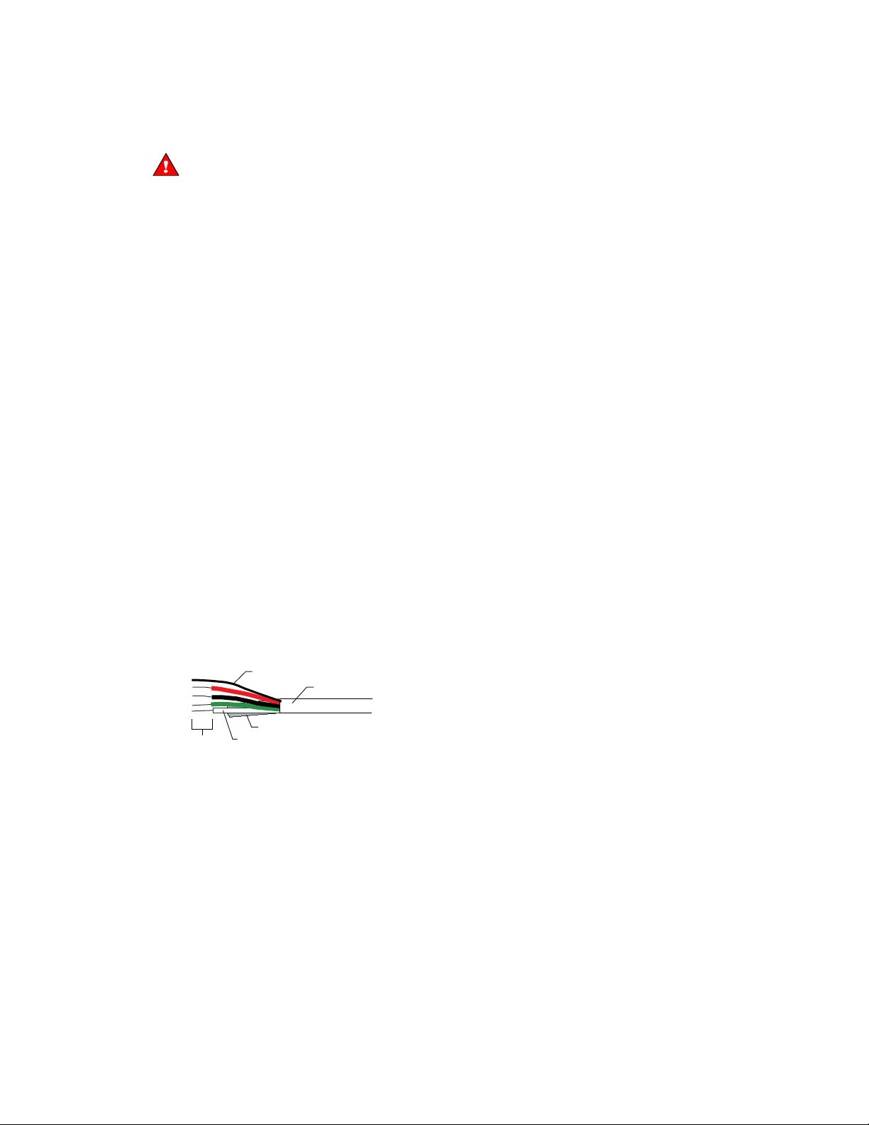
1 Strip the outer jacket from the cable for at least 4 inches (10.2 cm). Strip .25 inch (.6 cm) of insulation from
each wire.
2 Wire the sensor to the controller. See diagram below.
3 Using electrical tape, insulate any exposed resistor lead to prevent shorting.
4 Verify that the
jumper is set to
.
VVT Zone II Controller CARRIER CORPORATION ©2019
Installation and Start-up Guide All rights reserved
23
Page 28

Installing the VVT Zone II
SW3
Wiring a remote occupancy sensor
REMOTE
5 Set
on the sensor as shown below.
You can wire a normally open or normally closed dry-contact occupancy sensor to the VVT Zone II's
as shown below. The controller supplies the voltage needed for the input.
input
VVT Zone II Controller CARRIER CORPORATION ©2019
Installation and Start-up Guide All rights reserved
24
Page 29

Installing the VVT Zone II
Wiring equipment to outputs
WARNING
Wiring specifications
NOTE
Use the following wiring diagrams to wire zone terminal equipment to the VVT Zone II's outputs.
Single duct (page 26)
Single duct 2-position hot water (page 27)
Single duct modulating hot water (page 28)
Single duct SCR electric heat (page 29)
Single duct combination baseboard and ducted heat (page 30)
Single duct staged electric heat (page 31)
Fan box 2-position hot water (page 32)
Fan box modulating hot water (page 33)
Fan box SCR electric heat (page 34)
Fan box combination base board and ducted heat (page 35)
Fan box 2-stage electric heat (page 36)
Wiring field-supplied actuators to the analog output (page 37)
Disconnect electrical power to the VVT Zone II before wiring it. Failure to follow this warning could
cause electrical shock, personal injury, or damage to the controller.
To size output wiring, consider the following:
• Total loop distance from the power supply to the controller, and then to the controlled device
Include the total distance of actual wire. For 2-conductor wires, this is twice the cable length.
• Acceptable voltage drop in the wire from the controller to the controlled device
• Resistance (Ohms) of the chosen wire gauge
• Maximum current (Amps) the controlled device requires to operate
VVT Zone II Controller CARRIER CORPORATION ©2019
Installation and Start-up Guide All rights reserved
25
Page 30
Installing the VVT Zone II
Wiring diagram legend
Gnd
HWV
SAT
SCR
Space temp
sensor
T55 (OPT)
– – –
Single duct only
Ground
=
Hot water valve
=
Supply air temperature sensor
=
Silicon controlled rectifier
=
ZS sensors or Wireless Adapter for
=
wireless sensors
Alternate space temperature sensor
=
Field-supplied wiring
VVT Zone II Controller CARRIER CORPORATION ©2019
Installation and Start-up Guide All rights reserved
26
Page 31

Installing the VVT Zone II
Single duct 2-position hot water
VVT Zone II Controller CARRIER CORPORATION ©2019
Installation and Start-up Guide All rights reserved
27
Page 32

Installing the VVT Zone II
Single duct modulating hot water
VVT Zone II Controller CARRIER CORPORATION ©2019
Installation and Start-up Guide All rights reserved
28
Page 33

Installing the VVT Zone II
Single duct SCR electric heat
VVT Zone II Controller CARRIER CORPORATION ©2019
Installation and Start-up Guide All rights reserved
29
Page 34

Installing the VVT Zone II
Single duct combination base board and ducted heat
VVT Zone II Controller CARRIER CORPORATION ©2019
Installation and Start-up Guide All rights reserved
30
Page 35

Installing the VVT Zone II
Single duct staged electric heat
VVT Zone II Controller CARRIER CORPORATION ©2019
Installation and Start-up Guide All rights reserved
31
Page 36

Installing the VVT Zone II
Fan box 2-position hot water
VVT Zone II Controller CARRIER CORPORATION ©2019
Installation and Start-up Guide All rights reserved
32
Page 37

Installing the VVT Zone II
Fan box modulating hot water - ducted or baseboard
VVT Zone II Controller CARRIER CORPORATION ©2019
Installation and Start-up Guide All rights reserved
33
Page 38

Installing the VVT Zone II
Fan box SCR electric heat
VVT Zone II Controller CARRIER CORPORATION ©2019
Installation and Start-up Guide All rights reserved
34
Page 39

Installing the VVT Zone II
Fan box combination baseboard and ducted heat
VVT Zone II Controller CARRIER CORPORATION ©2019
Installation and Start-up Guide All rights reserved
35
Page 40

Installing the VVT Zone II
Fan box 2-stage electric heat
VVT Zone II Controller CARRIER CORPORATION ©2019
Installation and Start-up Guide All rights reserved
36
Page 41

Installing the VVT Zone II
Wiring field-supplied actuators to the analog output
High-torque actuator
NOTE
You can wire a high-torque actuator or parallel actuators to the controller's 0–10 Vdc analog output.
You can wire one of the following Belimo actuators to the VVT Zone II's analog output instead of using the
controller's built-in, 45 in.-lb (4 Nm) actuator.
NMX24-MFT P-10028 90 in.-lb (10 Nm) actuator with 0–10 Vdc control and 0–10 Vdc feedback
AMX24-MFT P-10028 180 in.-lb (20 Nm) actuator with 0–10 Vdc control and 0–10 Vdc feedback
1 Install the actuator according to the manufacturer's instructions.
2 Wire the actuator to the controller using the diagram below.
For proper operation and to prevent damage to the devices, use the same polarity for the actuator's power
and the VVT Zone II's power.
VVT Zone II Controller CARRIER CORPORATION ©2019
Installation and Start-up Guide All rights reserved
37
Page 42

Installing the VVT Zone II
Linked actuators
You can wire up to 4 of the following Belimo actuators to the VVT Zone II's analog output. Use like actuators so
that travel times and other parameters coincide.
LMX24-MFT P-10028 45 in.-lb (5 Nm) actuator with 0–10 Vdc control
NMX24-MFT P-10028 90 in.-lb (10 Nm) actuator with 0–10 Vdc control
AMX24-MFT P-10028 180 in.-lb (20 Nm) actuator with 0–10 Vdc control
1 Install the actuators according to the manufacturer's instructions.
2 Wire the actuators to the controller using the diagram below.
3 Set the direction rotation switch on each actuator to CW.
VVT Zone II Controller CARRIER CORPORATION ©2019
Installation and Start-up Guide All rights reserved
38
Page 43

Installing the VVT Zone II
IMPORTANT!
Properties
I/O Points > Hot Water Valve Max
200
NOTE
scaling to
If slaving 45° actuators, you must go to
>
for the slave actuator to correctly track the primary actuator.
and change
Maintain polarity if using the same power supply for more than one actuator.
VVT Zone II Controller CARRIER CORPORATION ©2019
Installation and Start-up Guide All rights reserved
39
Page 44

Start-up
This interface...
Provides a...
Field Assistant
Equipment Touch
i-Vu®
System Touch
CAUTION
Configuring the VVT Zone II's properties
NOTE
Start-up
Use one of the following interfaces to start up, access information, read sensor values, and test the controller.
application -
Runs on a laptop that connects to controller's Local Access port
device -
2
Connects to controller's Rnet port
application
Available for BACnet systems only
device
Available only for BACnet MS/TP systems.
1
Temporary or permanent
interface
Permanent interface
Temporary or permanent
interface
Temporary interface
Wire to a BACnet MS/TP network connector and a 24 Vac power supply 3
1
Requires a USB Link (Part #USB-L).
2
See the Equipment Touch Installation and Setup Guide for detailed instructions.
3
See the System Touch Installation and Setup Guide for detailed instructions.
If multiple controllers share power but polarity was not maintained when they were wired, the
difference between the controller's ground and the computer's AC power ground could damage the USB Link and
the controller. If you are not sure of the wiring polarity, use a USB isolator between the computer and the USB
Link. Purchase a USB isolator online from a third-party manufacturer.
To start up the VVT Zone II, you must configure certain points and properties. Appendix A (page 65) is a complete
list of all the points and properties, with descriptions, defaults, and ranges. These properties affect the unit
operation and/or control. Review and understand the meaning and purpose of each property before changing it.
• Unit Configuration properties (page 66)
• Setpoint Configuration properties (page 68)
• Service Configuration properties (page 77)
• Linkage properties (page 87)
See Appendix A (page 65) for a complete list of the controller's points/properties.
Engineering units shown in this document in the defaults and ranges are strictly for reference. You must
enter an integer only.
VVT Zone II Controller CARRIER CORPORATION ©2019
Installation and Start-up Guide All rights reserved
40
Page 45

Start-up
Configuring ZS Sensors
Main ZS
Sensor
Properties
Control Program
Service
Configuration
Details
NOTE
(page 77)
ZS Sensor Binder
ZS Zone Temp
ZS Zone Humidity
ZS Zone CO2
ZS model to show on graphic
Setpoint Adjustment
Occupancy
Override
Performing system checkout
NOTE
CAUTION
The VVT Zone II automatically detects 1 ZS temperature sensor set to address (1). This sensor is labeled
.
You must configure the ZS Sensor properties in the i-Vu® application or Field Assistant as follows:
• Add more ZS temperature, humidity, or CO2 sensors in the
settings on the
See Service Configuration
• Configuring the
○
○
○
○
• Configure
• Set
section. Ctrl+click on the property name to open the microblock popup and configure the
tab.
, and then the following as needed:
and
. See Setpoints (page 68).
properties. See Maintenance (page 83) for details.
• Alarm and Maintenance indications on the ZS Pro (display model) sensors. See Appendix C: ZS Sensor
display for VVT Zone II (page 94).
>
tab >
for details.
1 Verify that all power and communication connections are correct and tight.
2 Verify that all zone terminals, ductwork, and zone controllers are properly installed and set according to
installation instructions and job requirements.
3 Verify that all air duct connections are tight.
4 Verify that zone terminal fans and system controls operate properly. Verify that actuator screws are properly
tightened.
5 At the zone terminals, check electrical system and connections of any optional electric reheat coil. If hot
water reheat is used, check piping and valves against job drawings.
6 Verify that all zone terminal dampers are fully open.
7 If using an air source with field-installed controls, make sure controls and sensors have been installed and
wired per manufacturer installation instructions.
8 Verify that the air source motor starter and, if applicable, the Hand/Off/Auto (HOA) switch are installed and
wired.
9 Verify that the area around the air source is clear of construction dirt and debris.
10 Verify that final filters are installed in the air handler(s). Dust and debris can adversely affect system
operation.
11 Verify that the space sensor and all optional sensors are reading correctly.
You must use the i-Vu® application or Field Assistant to configure ZS Sensors.
Before starting the air source fan, make sure the zone terminal dampers are not closed.
Starting the fan with dampers closed will damage the system ductwork.
VVT Zone II Controller CARRIER CORPORATION ©2019
Installation and Start-up Guide All rights reserved
41
Page 46

Start-up
Commissioning the VVT Zone II
Properties > Configuration > Service Configuration
Pressure Dependent Control > Details
Test and Balance
Calibrated Damper Close
Calibrated Damper Open
Automatic Control
Locks
Fan
Lock value to
On
Apply
Properties > I/O Points
Hot Water Valve
Hot Water Valve
Linkage
Airside Linkage Status
Active
CAUTION
Balancing the system
NOTE
Using Field Assistant or the i-Vu application:
1 Calibrate the damper travel.
a) Go to
b) Click
c) Click
2 For Parallel or Series Fan terminals – in the
select
3 For modulating hot water reheat – Go to
the controller is configured for Single Duct, make sure the air source fan is on. If ducted heat, verify the heat
works by verifying that the SAT rises. For baseboard heat, physically check the heating element for proper
temperature rise. Release the
4 Release the fan.
5 If the controller is part of a linked system, verify
. Click
and verify it travels to the full open.
to return the damper to normal operation.
in the droplist. Click
. Verify the fan's operation.
.
>
and verify it goes to the closed position.
section, select the
>
's
tab, then lock
shows
tab >
checkbox, then
to 100%. If
.
Pressing the actuator release button and moving the damper or disconnecting the actuator ribbon
connector while the bypass controller is powered will cause the damper position to be out of calibration. To
recalibrate the damper position, you must perform steps 1a–1c above or power cycle the controller.
Most VVT system airflow designs are based on cooling requirements which require a greater CFM (liters/second)
flow than heating requirements. Using this balancing procedure, you will adjust the cooling airflow first. If the
heating and cooling maximum airflow requirements are the same, you will not need to balance the heating airflow.
We recommend that the heating minimum airflow settings for all the zones in the system be set to maintain
the air source’s design minimum heat CFM (liters/second) airflow across its heat exchanger to prevent damage to
the equipment.
There are two methods of balancing the system:
• Use the i-Vu application or Field Assistant – Complete the following 3 steps to perform the system balancing.
• Use the Test & Balance program – Test & Balance can perform the 3 steps below, including shutting down
the linked air source and performing global commands to all zones in the system. Do items 1–5 in Step 1
below prior to using Test & Balance. See Test & Balance's Help for required steps to complete the balancing
procedure.
VVT Zone II Controller CARRIER CORPORATION ©2019
Installation and Start-up Guide All rights reserved
42
Page 47

Start-up
Step 1: Prepare for balancing
Properties
Configuration > Service Configuration
Service Test
Service Test
Fan Test
Step 2: Balance each zone
Properties > Control Program > Configuration > Service Configuration > Pressure Dependent Control
Details
Cool Max
Damper Full Close
Fan
Lock value to
On
Apply
Cool Max
Pressure Dependent Control > Details
Cool Min
Cool Min
Cool Min
Fan
Lock value to
Apply
Fan
Lock value to
1 Log in to the i-Vu® application with an Administrator or Installer security level, or use Field Assistant.
2 Make sure the air source and its controller have been properly started and can run as a stand-alone unit.
3 Make sure the zone and bypass controllers have been addressed, commissioned, and started.
4 Verify that a manual damper is installed upstream of the zone damper. This damper will be used to adjust the
maximum design airflow to the space when the zone damper is at 100% open. We strongly recommend that
you do not use the damper Cool or Heat Max damper configuration setting for this purpose. Exception: If the
design maximum airflow for one mode is less the other, the maximum damper position configuration may be
used to adjust the designed airflow of that mode.
5 Verify that zone controllers supplying multiple registers have manual dampers on each register branch duct
for balancing the design airflow through each register.
6 Disable the air source heating and cooling outputs using one of the following methods:
○ Physically disconnect the air source controller’s output wiring to the unit, then enable the fan.
○ In the i-Vu or Field Assistant tree, select the RTU Open or WSHP Open controller. Go to
>
and enable
all other outputs are disabled.
and
>
. Make sure
1 In the i-Vu® or Field Assistant tree, select the zone controller that is physically closest to the air source. Go to
tab.
2 Do one of the following:
○ Single Duct or Parallel Fan zone terminals – Click
open position. Check the zone for design cooling maximum airflow using certified measuring devices.
Make adjustments using the manual volume damper located upstream of the zone damper.
○ Series Fan zone terminals – Click
position. Wait 30 seconds after the damper is closed, select the
select
in the droplist. Click
backwards. When the fan starts, click
Check the zone for design cooling maximum airflow using certified measuring devices. See the zone
terminal manufacturer's instructions to adjust the fan speed to meet design airflow requirements. After
you set the fan speed, verify that the zone terminal plenum air intakes do not have a positive airflow. If
so, adjust the manual volume damper located upstream of the zone damper so that the airflow is not
positive or negative.
Note the zone’s name in the tree. You will need it when setting the system static pressure setpoint.
3 Check all branch duct terminal registers for design flow. If necessary, adjust the manual volume dampers in
the branch ducts.
4 On the zone’s
minimum position. Type the desired damper position next to
value. If you do not have a design value, set the value to no less the 10% for minimum ventilation.
5 Parallel Fan Zone Terminals only - To adjust Parallel Fan airflow, make sure
's
manufacturer's instructions on adjusting the fan speed to meet design airflow requirements. When finished,
clear the
checkbox, then select On in the droplist. Click
's
checkbox.
to override the zone damper to its maximum
to override the zone damper to its fully closed
's
checkbox, then
. You must follow this procedure to prevent the fan from turning
to open the zone damper to its maximum position.
tab, click
to set the zone damper to its cooling
to adjust the airflow to the design
is active, select the
. See the zone terminal
>
VVT Zone II Controller CARRIER CORPORATION ©2019
Installation and Start-up Guide All rights reserved
43
Page 48

Start-up
Vent
Vent
Heating Max Damper Position
Cooling Max Damper Position
Heating Max
Damper Position
Reheat Min
Reheat Min
Heat Max
Heat
Max
Heat Min
Step 3: Set the system static pressure
NOTE
Properties > Control Program > Configuration > Service Configuration
Pressure Dependent Control > Details
Cool Max
Heat Max
6 Click
to set the zone damper to its ventilation position. Type the desired damper position next to
adjust the airflow to the design value. If you do not have a design value, leave the value at 50% for minimum
ventilation.
7 Series Fan Zone Terminals only - If the zone maximum heating airflow design requirements are the same as
cooling, the
the heating requirement is less than the cooling requirement, type the appropriate value in
8 If the terminal has ducted reheat, click
desired damper position next to
per the design requirements.
9 If the zone maximum heating airflow design requirements are the same as cooling, skip this step. If they are
less than cooling, click
to force the zone to its maximum heating position. Check the zone for
design heating maximum airflow using certified measuring devices. Type the damper position next to
.
10 To set the heating minimum airflow, click
sum of this setting for all zones in the system be equal to the minimum heat CFM (liters/second)
requirements of the air source.
11 Repeat steps 1 through 10 for each zone until all zones have been balanced.
For the air source to deliver the required airflow, you must set the bypass controller's static pressure setpoint high
enough to provide the demand but low enough to maintain reasonable noise levels. The bypass controller
maintains static pressure by controlling a damper or a supply fan VFD. You need the following data to set the
static pressure:
• The air source’s design maximum airflow in CFM (liters/second) (manufacturer’s data)
should be 100%, same as the
to force the zone to its reheat damper position. Type the
to adjust the airflow to its design reheat position.
, then type the damper position. We recommend that the
to
. If
• The system’s design external static pressure (inches or water). This is the amount of static pressure that the
air source is designed to deliver at its maximum design airflow in CFM (liters/second) (supplied by the
mechanical design engineer).
• The maximum cooling or heating (whichever is greater) CFM (liters/second) requirements for all zones
connected to the air source
The air source fan must have been tested and certified that it can deliver the above requirements.
The sum of the maximum CFM (liters/second) requirements of all zones will generally exceed the air source's
maximum CFM (liters/second) rating by 10 to 20%. This is by design and based on a factor known as diversity. It
works on the basis that under normal design heating and cooling conditions, not every zone will be 100% open.
Knowing this, you will need to force open only zones whose sum CFM (liters/second) is equal to the unit design
CFM (liters/second) . With the bypass damper fully closed (0%) or supply fan VFD at 100%, the bypass controller's
static pressure should be the controlling setpoint.
To set the static pressure:
1 Starting with zone furthest from the air source and working towards it, add up the maximum design CFM
(liters/second) airflow of the zones until the sum equals the air source’s design CFM (liters/second) (+/-5%).
Note each zone that you included.
2 For each zone noted in step 1, go to
tab. Click
or
(whichever has the highest design
>
max airflow) to force the damper to its maximum open position.
VVT Zone II Controller CARRIER CORPORATION ©2019
Installation and Start-up Guide All rights reserved
44
Page 49

Start-up
Properties > Control Program > Status
Static
Pressure
Unit Configuration > Bypass Control
Details
Damper Position
VFD Output
Duct Static Pressure
Setpoint
Damper Position
VFD Output
Duct Static Pressure Setpoint
Damper Position
VFD Output
Duct Static
Pressure Setpoint
Damper Position
VFD Output
Pressure Dependent Control > Details
Automatic Control
Properties > Control Program > Configuration > Service
Configuration > Service Test
Service Test
Fan Test
CAUTION
3 In the tree, select the Bypass controller, then go to
○ If
○ If the
value, then go to
field.
the
is 100%. If not, repeat the process, adding .05” (.012 kPa) to the previous
is 0% or
is not 0% or
until the
field. Wait 1–2 minutes, then verify that the
4 For each zone in the system that was balanced, go to its
click
to return the zone to normal control.
>
tab.
is 100%, enter the static pressure in the
is not 100%, enter the static pressure +.1” (.025 kPa) in
is 0% or
is 100%.
5 In the tree, select the air source controller, then do one of the following.
a) For an RTU Open or WSHP Open controller, go to
and disable
and
.
b) For any equipment whose wiring was disconnected to insure that only the fan only was running,
reconnect it the wires for normal operation.
You must complete steps 4 and 5 to prevent loss of temperature control to the space and to
maintain normal operation of the system.
. Note the
tab, then
is 0% or
VVT Zone II Controller CARRIER CORPORATION ©2019
Installation and Start-up Guide All rights reserved
45
Page 50

Sequence of operation
Temperature sensors
Sensors
Notes
Space temperature sensors:
System Space
Temperature
Duct temperature sensors:
Sequence of operation
The VVT Zone II supports 3 types of pressure-dependent terminal configurations:
• Single duct
• Series fan-powered
• Parallel fan-powered
The controller can operate as part of a linked VVT system or as a stand-alone controller.
The VVT Zone II supports the following temperature sensors:
• Wireless Standard or Plus1
• ZS Standard, Plus, Pro2
• T553
• Duct Air Temperature (DAT)
• Supply Air Temperature (SAT)
1
To configure the control program for the desired user interaction with the sensor, see the Wireless Sensors
Application Guide. For detailed instructions, see the Wireless Sensors Installation Guide.
2
For basic user instructions, see the ZS Sensor User Guide. For detailed installation instructions, see the ZS
Sensors Installation Guide.
3
See the Carrier Sensors Installation Guide for details on T55 sensors.
VVT Zone II Controller CARRIER CORPORATION ©2019
Installation and Start-up Guide All rights reserved
46
You can average up to 5 wireless sensors.
You can average up to 5 ZS sensors - a combination of temperature,
2
humidity, and/or CO
sensors.
Push the sensor's override button from 2 to 10 seconds to initiate a
timed override.
If a network space temperature value is used, that value must be
written to the BACnet space temperature point (system_spt) at 1 to 5
minute intervals or on a COV of 0.1
°F (.06 °C) .
To reference another zone as your space temperature input, read the
BACnet point zone_temp by using the network point
.
10K Type II.
If the zone does not have ducted reheat, install a DAT sensor on the
inlet of the damper.
If the zone has ducted reheat, install an SAT sensor downstream of the
reheat source. The SAT is used in controlling the reheat.
The DAT/SAT determines the air source mode if Linkage
communication fails or if the controller is stand-alone. See Air Source
Mode Determination (page 54) for details.
Page 51

Sequence of operation
Zone airflow control
Vent
Position
Single duct with reheat
Reheat Min Damper Position
Parallel fan terminals
Parallel Fan On Value
Parallel Fan On Value
Series fan terminals
Power Fail Start Delay
Damper Actuator(s)
The VVT Zone II provides pressure-dependent zone temperature control by modulating its built-in damper actuator
to control the flow of primary air into the zone. The controller uses PID control to calculate the damper position
based on the difference between the zone’s temperature and setpoints.
The air source mode determines if the primary air can meet the zone’s need. If the zone controller is in a linked
system, the air source mode is determined by the air source. If the zone controller is stand-alone or if linkage
communication fails, the mode is determined by the controller's SAT. See Air source mode determination (page
54). If the air source mode is the same as the zone’s local mode, the damper is positioned between the mode’s
configurable minimum and maximum damper position. If not, the damper is positioned at the mode's minimum
damper position to insure sufficient minimum airflow at the air source.
When the air source mode is Vent and the zone’s temperature demand is satisfied, the damper moves to its
to increase airflow and ventilation to the space.
– The
allows an increase of primary airflow across the
terminal’s ducted heating coil when the terminal is operating its local heat while the air source mode is Cool. This
provides the ability to lower the cooling minimum airflow limits while providing the necessary airflow when the
terminal is heating to ensure design load conditions and electric heater minimum airflow.
– The controller's
determines when the fan turns on to increase
airflow at the zone’s diffusers and prevent cold air from dumping into the zone when the system mode is Cool.
This is achieved by increasing the volume and temperature of the air exiting the diffusers. Should the zone’s
damper close below the
, the parallel fan is energized to mix ceiling plenum air with the
primary air to increase total airflow and ventilation to the zone. The fan turns off when the damper position opens
to 1% above the setpoint.
The fan also starts in Heat mode if the zone is configured for ducted heat as described in Zone reheat control
(page 48).
– The fan energizes when the air source fan is on if the zone controller is part of a linked
system or in the unoccupied heat mode and the equipment fan is off. If the zone controller is stand-alone, the fan
runs continuously. There is a fan start delay on transition to occupied, based on the
the fan starts, the damper closes. The damper position must be less than 5% for 10 seconds before the fan starts
to prevent the fan from starting backwards.
See Appendix B: VVT terminal modes (page 92).
– The VVT Zone II's built-in 35 in/lb (4 Nm) actuator has a 205 second full travel time for 90°
operation. For field retrofit applications, the actuator can be adjusted for a damper stroke between 30° and 90°,
and it can be configured to move clockwise (default) or counterclockwise.
If the built-in actuator's torque is insufficient for large damper applications, the VVT Zone II's analog output can
drive an external, 0-10 volt, high-torque actuator. Or, the controller can drive one or more additional slave
actuators. A slave actuator must be mounted and configured to fully close the damper when the output signal is 0
volts. See Wiring field-supplied actuators to the analog output. (page 37)
. Before
VVT Zone II Controller CARRIER CORPORATION ©2019
Installation and Start-up Guide All rights reserved
47
Page 52

Sequence of operation
Zone reheat control
Heat Types
Maximum Heating SAT
Heating Lockout
Temperature
Modulating Hot Water / Steam Heating Heat
Maximum Heating SAT
SCR Electric Heat
Two-Position Hot Water / Steam Heating Heat
Maximum Heating SAT
Electric Auxiliary Heat
Maximum Heating SAT
Combination Modulating Baseboard / Electric Heat
Maximum Heating SAT
Parallel Fan Heat On Delay
Parallel Fan Heat
On Delay
The VVT Zone II can be configured for one of the following
• Modulating Hot Water/Steam
• Modulating SCR Electric
• Two Position Hot Water/Steam
• Staged Electric Heat (2 stages for Series/Parallel Fan, 3 stages for Single Duct.)
• Combination Modulating Baseboard/Staged Electric Heat (2 stages for Series/Parallel Fan, 3 stages for
Single Duct.)
All of the above except Combination Modulating Baseboard/Staged Electric Heat can be ducted or non-ducted
(baseboard). For ducted heat and Combination Modulating Baseboard/Staged Electric Heat, an SAT sensor
(33ZCSENSAT) must be installed in the duct downstream of the heat source. The controller has a configurable
terminal’s ducted heat is operating.
If the network provides the OAT, heating can be disabled if the OAT rises above the configured
water or steam valve connected to the discharge air heating coil. The valve opens and closes as needed to satisfy
the zone's heating requirements. For ducted heat, the terminal’s heat supplements heat from the primary air
source if it is in heating mode and is controlled so that the SAT does not exceed the
[105°F (40.5°C) default]. For baseboard heating (non-ducted heat), the valve modulates to keep the zone’s
temperature at the heating setpoint.
input. The output increases as needed to satisfy the zone’s heating requirements. For ducted heat, the terminal’s
heat supplements heat from the primary air source if it is in heating mode and is controlled so that the SAT does
not exceed the Maximum Heating SAT [105°F (40.5°C) default]. For baseboard heating (non-ducted heat), the
SCR heat output modulates to keep the zone’s temperature at the heating setpoint.
water or steam valve connected to the discharge air heating coil. The valve opens and closes as needed to satisfy
the zone's heating requirements. For ducted heat, the terminal’s heat supplements heat from the primary air
source if it is in the heating mode and is controlled so that the SAT does not exceed the
[105°F (40.5°C) default]. For non-ducted (baseboard) heating, the valve is controlled to keep the zone’s
temperature at the heating setpoint.
supplements heat from the primary air source if it is in the heating mode and is controlled so that the SAT does
not exceed the
stages are controlled as needed to keep the zone’s temperature at the heating setpoint.
open hot water or steam valve connected to a perimeter baseboard radiation system and control up to 2 stages of
ducted electric heat. The valve modulates to satisfy the zone's heating requirements. If the valve cannot meet the
load, electric heat is used. The terminal’s electric heater supplements heat from the primary air source if it is in
heating mode and is controlled so that the SAT does not exceed the
default].
ceiling plenum. If the heating requirement is not met by the end of the delay, reheat is enabled.
.
to save energy. During the delay (15 minute default), only the fan operates to recycle heat from the
for supply air temperature control. The zone controller monitors the (SAT) when the
– The controller modulates a normally closed or normally open hot
– The controller modulates an SCR heat output connected to the SCR electric heat control
– The controller operates a normally closed or normally open hot
– The controller operates 1 or 2 stages of electric heat. For ducted heat, the terminal’s heat
– For Parallel Fan terminals only, the controller has a configurable
[105°F (40.5°C) default]. For non-ducted (baseboard) electric heat, the
– The controller can modulate a normally closed or normally
to meet the zone's heating requirements:
[105°F (40.5°C)
VVT Zone II Controller CARRIER CORPORATION ©2019
Installation and Start-up Guide All rights reserved
48
Page 53

Sequence of operation
Fan Heat Off Delay
Fan Off Delay
Demand control ventilation (DCV) and dehumidification using optional sensors
RH/CO2
NOTE
Enable
DCV Max Vent Airflow
Maximum RH Override Airflow
Demand Control Ventilation (DCV)
DCV Start Ctrl Setpoint
DCV Max Ctrl Setpoint
DCV Max Vent Damper Position.
Cooling Min Damper Position
Heating Min Damper Position
Dehumidification
Occupied RH Control Setpoint
Maximum RH
Override Airflow
NOTE
– For fan-powered terminals, the controller has a configurable
. After the heating
coil de-energizes, the fan continues to run for the length of the delay to deliver to the zone any heat stored in the
coil. The default delay of 2 minutes is optimal for ducted hot water coils. For ducted electric heat coils, the
nominal delay is approximately 1 minute. For baseboard and non-ducted heat, the delay should be set at 0.
This feature applies to parallel fan terminals in both occupied and unoccupied mode and series fan terminals in
the unoccupied mode if the air source fan is off.
The VVT Zone II’s
have a 5-volt maximum output. The range is configurable as either 0–5 or 1–5 volts (1–5 volt supports 4–20 mA
sensors with a 250 ohm resistor). The controller's low and high sensor input configuration allows for a wide range
of sensors.
The controller can also support both DCV and dehumidification functions, by using a system RH or CO2 sensor
input connected to another controller.
If the connected sensor and/or system sensor value are used by the air source through Linkage, set the
appropriate control type to
input supports an optional CO2 sensor or Relative Humidity (RH) sensor. The sensor can
. If you do not need local control at the zone, set
or
to 0.
– Requires CO2 sensor
The zone controller monitors the CO2 sensor and can override the temperature control to respond to increasing
CO2 levels when the zone is occupied. If the sensor’s value exceeds the
and the air source
is in cooling or ventilation mode, the controller increases airflow to the zone at a base rate defined by ASHRAE,
and then proportionally increases ventilation if the CO2 level continues to increase. If the sensor's value exceeds
the
When the zone is unoccupied, the
, the controller modulates the damper to its
and
provide base
ventilation.
If the controller is configured for reheat, the heating setpoint is temporarily increased to a value halfway between
the heating and cooling setpoints. If the zone temperature drops below the heating setpoint, the DCV override is
temporarily suspended and the damper returns to normal control until the zone temperature is satisfied.
– Requires RH sensor
The zone controller monitors the RH sensor and can provide dehumidification if the sensor's value exceeds the
. If the zone is occupied and does not require heating, and the air source is
operating in a cooling mode and providing primary air with a sufficiently low dew point, the controller overrides the
damper control to increase airflow to the zone. During the dehumidification mode, the heating setpoint is
temporarily increased to a value halfway between the heating and cooling setpoints to prevent overcooling the
zone. The controller uses a PID control loop to provide dehumidification. The controller has a
If both control functions are enabled, the zone will control to the greatest calculated damper position of the
setting to prevent excessive airflow during dehumidification.
three values (temperature, RH, or IAQ).
VVT Zone II Controller CARRIER CORPORATION ©2019
Installation and Start-up Guide All rights reserved
49
Page 54

Sequence of operation
Occupancy
Occupancy Schedules
NOTES
Occupancy Schedules
Remote Occupancy Override
Remote
Occ
Override Normal Logic State
Learning Adaptive Optimal Start
learned heating capacity
learned cooling capacity
Learning Adaptive Optimal Start
Optimal Start
Learning Adaptive Optimal Start
Effective Setpoints
Setpoints
BAS On/Off
Occupancy Schedules
Disable
Occupied
Unoccupied, Optimal Start
The VVT Zone II's operation depends on the zone's occupancy state as determined by occupancy schedules or a
remote occupancy override.
• A local schedule set up directly in the controller using a touchscreen device or Field Assistant.
• A network schedule from an i-Vu internal router. The VVT Zone II must be networked to an i-Vu Open Router or
an i-Vu internal router.
• A System Occupancy network point. This point links the controller occupancy to another controller in the
network so that multiple zones can follow the occupancy of another VVT Zone or other controller on the
network.
To set up occupancy schedules, you first define a schedule for each day of the week and then define schedules
for the exceptions, such as holidays. The exceptions can be based on a date, a date range, or a week and day.
• The
• A network schedule downloaded from the i-Vu application will overwrite a local schedule that was set up in a
touchscreen device or Field Assistant.
dry contact of an occupancy sensor located in the zone. The controller can override the occupancy state based on
whether or not the space is actually occupied. If the occupancy sensor contact is in the same state as
opposite state, it overrides the zone into the unoccupied mode. The input can be configured for normally closed or
normally opened contact types and is set to Open by default so that it does not affect the controller occupancy
operation if left unused.
period of time to achieve the occupied setpoint by the time scheduled occupancy begins. This learning adaptive
algorithm uses the
setpoints prior to the occupied start time. The algorithm calculates a learned cooling and heating capacity during
the previous unoccupied time. Set the
. When the
achieved when occupancy begins. Adjustment amounts are defined in the thermographic color fields located
directly above the
set to
– This function allows third party control of the controller occupancy.
to use this function. When set to
For additional information on ZS Sensor occupancy and override settings, see Maintenance (page 83) Points and
Properties.
– An occupancy schedule can be one of the following:
property must be enabled (default).
– The controller monitors its
input that is typically connected to the isolated,
setting, the zone follows its normal occupancy schedule. If the contact is in the
– This function gradually adjusts the unoccupied setpoints over a specified
and
graph under
routine runs, adjustments are based on the color that is
.
or
values to calculate the effective
recovery period from 1 to 4 hours in
must be
is automatically disabled.
VVT Zone II Controller CARRIER CORPORATION ©2019
Installation and Start-up Guide All rights reserved
50
Page 55

Sequence of operation
Alarms
Space Temp Sensor Alarm
Space Temperature Alarm
Occupied Alarm Hysteresis
Supply Air Temperature Alarm
High SAT
Alarm Limit
Low SAT Alarm Limit
High SAT Alarm Limit
Maximum Heating SAT
Space Relative Humidity Alarm
Occ High RH Alarm Limit
Unocc High RH Alarm
Limit
Occ High RH Alarm Limit
Indoor Air Quality Alarm
Occupied High CO2 Alarm Limit
Occupied High CO2 Alarm Limit
Filter Alarm
Filter Runtime
Filter Service Alarm
Timer
Reset Filter
Alarm
Airside Linkage Alarm
– The VVT Zone II monitors each space temperature sensor and the network input for
space temperature. If no valid space temperature value is available, the controller generates an alarm and
disables all local heating or cooling. The controller modulates the damper to the minimum heat, minimum cool, or
ventilation position based on the air source mode. Normal operation resumes when the controller detects a valid
sensor value.
setpoint. The occupied alarm setpoint is the configurable
– The controller generates an alarm if the space temperature exceeds the alarm
(5 °F [2.78 °C] default)
subtracted from and added to the configured occupied heat and cool setpoints. The configurable unoccupied high
and low alarm setpoints have a fixed 10 minute alarm delay. When a transition from unoccupied to occupied
occurs or the occupied temperature setpoints are changed, causing an alarm condition, the controller
automatically calculates an alarm delay of 10 minutes for each degree of change. The delay prevents unnecessary
alarms and gives the zone time to correct the alarm condition. The alarm returns to normal when the space
temperature goes between the current mode’s setpoints.
(120°F [48.9°C] default) or falls below the
than 5 minutes. The hysteresis for return to normal is 3
a value at least 15
°F (8.3 °C) above the
– The controller generates an alarm if the SAT exceeds the configured
°F (1.6 °C) . The
or the maximum discharge temperature from
(45°F [7.2°C] default) for more
should be set to
the air source, whichever is greater.
alarm if the sensor's value exceeds the
(100% rh default). The controller provides a 30-minute alarm delay during unoccupied periods. During
occupied periods, the controller uses the
– If a Space Relative Humidity (RH) sensor is installed, the controller generates an
(100% rh default) or the
. When a transition from unoccupied to
occupied occurs or the occupied high alarm limit is lowered causing an alarm condition to occur, the controller
automatically calculates an alarm delay of 5 minutes per %RH multiplied by the amount of the change. The delay
prevents unnecessary alarms and gives the zone time to correct the alarm condition. The hysteresis for return to
normal is 3% RH.
if the sensor's value exceeds the
– If a CO2 sensor is installed, the controller generates an alarm during occupied periods
. When a transition from unoccupied to occupied
occurs, or if the occupied alarm limit is changed to a value that causes an alarm condition to occur, the controller
automatically calculates an alarm delay based on the error from setpoint (15 minutes minimum, 4 hours
maximum). The delay prevents unnecessary alarms and gives the zone time to correct the alarm condition. To
disable the IAQ alarm, set
to 0. The default value is 1100ppm. The hysteresis for
return to normal is 100ppm.
operation and generates an alarm when the
– For series or parallel fan-powered terminals, the controller monitors the accumulated hours of fan
hours exceed the configured
limit. The default value is 0 hours which disables the alarm. The alarm can be reset by setting
to On or resetting the configured alarm limit to 0 hours.
– The slave zone controller generates an alarm if it does not receive linkage information for
5 minutes. If the controller is the VVT Master, it generates an alarm if it does not communicate with its air source
for 5 minutes. A return-to-normal is generated after successful Linkage communication resumes.
VVT Zone II Controller CARRIER CORPORATION ©2019
Installation and Start-up Guide All rights reserved
51
Page 56

Sequence of operation
Demand limiting
Linkage
Linkage Callers
Linkage Callers
Inhibit Cooling Call from this zone?
Yes
Inhibit Heating Call from this zone?
Yes
Demand limiting is a cost-saving strategy to reduce energy consumption. The strategy expands the setpoints when
the system reaches one of 3 levels of consumption. With the expanded setpoints, the equipment works less,
thereby saving energy.
If the VVT Zone II receives a demand limit signal through the network, it expands its setpoints based on the
demand level. The default amounts are:
• Demand Level 1: 1
• Demand Level 2: 2 °F (1.1 °C)
°F (.6 °C)
• Demand Level 3: 4
The i-Vu Control System uses linkage to exchange data between the zone terminals and their air source to form a
coordinated HVAC system. The system's air source controller, zone controllers, and bypass controller are linked so
that their data exchange can be managed by one zone controller configured as the VVT Master.
The VVT Master gathers the following information from the slave zone controllers: occupancy status, setpoints,
zone temperature, relative humidity, CO
mathematical calculations and algorithms on the data and then sends the composite information to the air
source. The VVT Master receives information from the air source such as mode, supply air temperature, and
outside air temperature, if present, and passes that information to all linked controllers.
The VVT Master determines system operation by prioritizing heating and cooling requirements from all the zones
based on their occupancy and demand. The VVT Master scans the system continuously to determine if any zones
are occupied. Occupied zones are a higher priority than unoccupied zones. The VVT Master evaluates all the
occupied zones' heating or cooling demands and sends a request to the air source for:
• Cooling, if the number of occupied zones with cooling demands exceeds the number of occupied zones with
• Heating, if the number of occupied zones with a heating demand exceeds or is equal to the number of
A Linkage caller zone is determined by two user-adjustable parameters, A binary value is used to inhibit any
individual zone from becoming a heat or cool caller.
If
Likewise, if
Next, if both of the above are set to No, then the amount of zone temperature deviation from setpoint determines
when a zone becomes a caller. For cooling, this is determined by the amount of the yellow setpoint band. A zone
must exceed this band and enter into the orange band to become a cooling caller. The yellow band by default is
1
be counted as a cooling request.
The light blue band is used to determine the deviation required to become a heating caller. It is also set to a
default value of 1
If no zones are occupied, or no occupied zones require heating or cooling, the VVT Master performs the evaluation
described above for the unoccupied zones.
°F (2.2 °C)
level, damper position, and optimal start data. The VVT Master performs
2
heating demands, and the demand is greater than or equal to the number of configured
.
is set to
, then this zone is ignored when determining total cooling calls.
Is set to
, then this zone’s heating requirement will be ignored.
.
°F (.5 °C), therefore the space temperature must exceed the cooling setpoint by more than 1 °F (.5 °C) to
°F (.5 °C), but you can adjust it.
VVT Zone II Controller CARRIER CORPORATION ©2019
Installation and Start-up Guide All rights reserved
52
Page 57

Sequence of operation
The VVT Master then gathers the following information and sends it to the air source:
• The setpoints and zone temperature from the zone with the greatest demand for the requested air source
mode (heating or cooling). (This zone is called the reference zone.)
• The system occupancy status
• Most open damper position from any zone
• RH and CO
values (if applicable)
2
The air source responds by sending the air source mode, supply air temperature, and outside air temperature. The
air source verifies the mode by comparing its supply air temperature to the space temperature received through
Linkage. See the air source documentation for operation and parameters used to verify its mode. This verification
allows the VVT system to determine if the desired air source mode is actually being provided. For example, if the
VVT Master sends a request for heating and the air source does not have heat or it’s heat has failed, the air
source's actual mode indicates that and its current mode is sent to the zones so that they can control accordingly.
The system remains in that mode until all zones of that demand are satisfied or until the System Mode Reselect
Timer (factory default is 30 minutes) causes a forced re-evaluation of the system. If there is no demand for the
opposite mode, the reselect timer starts again and the current mode continues until all zones are satisfied or until
the reselect timer expires, repeating the process. If there is a demand for the opposite mode, the VVT Master
sends the reference zone's space temperature and setpoints to the air source and restarts the reselect timer. The
air source re-evaluates its demand based on the new information and goes to the Vent mode until the new mode
can be verified as described above. The amount of time this takes is determined by the air source’s operating
parameters.
The VVT Master continuously evaluates the system and updates the air source with the most current system
demand. Based on the evaluation, the reference zone can change from one zone to another. The evaluation
process continues until there is no demand from any zone or the 30 minute timer causes a re-evaluation of the
system conditions.
If no heating or cooling is required or the current air source mode is satisfied, the VVT Master calculates the
weighted average of the occupied and unoccupied heating and cooling setpoints. It also calculates a zone
temperature that is midway between the setpoints (occupied or unoccupied based on the system’s current
occupancy status). This information, plus the occupancy status, is sent to the air source so that its current mode is
disabled and the unit ceases heating or cooling operation. If the system is occupied, the air source fan and OA
damper, if applicable, operate to maintain proper ventilation.
VVT Zone II Controller CARRIER CORPORATION ©2019
Installation and Start-up Guide All rights reserved
53
Page 58

Sequence of operation
Linkage modes and operation
Linked air source modes
OFF
WARMUP
HEAT
FREECOOL
COOL
PRESSURIZATION
EVACUATION
VENT
Local air source modes
HEAT
mode based on its own SAT. The following modes can be sent by the air source depending on its capability and
configuration:
Air source fan is off. Terminal damper is positioned approximately 70%
Air source fan is on and providing first cycle of heat when changing from
Air source fan is on and providing heat. The terminal modulates its primary
Air source fan is on and providing cooling using only the economizer and
Air source fan is on and providing cooling. The terminal modulates its
Evacuation is usually the result of a fire-life safety input at the air source
All terminals treat VENT mode the same as the COOL mode. For VVT
See the air source’s installation manual for more specific operation.
controller assumes that the fan is always on and monitors its SAT sensor to determine if the primary air source is
providing heating, cooling, or recirculating air in a fan-only or ventilation mode.
For Series or Parallel Fan controllers when the zone terminal fan is off or for
– In a linked system, the air source determines its operating mode and qualifies that
open to allow for system restart.
unoccupied to occupied. It may also be used as an equipment safety to
increase system airflow. The terminal’s heating setpoint temporarily
increases to the midpoint between the configured occupied heating and
occupied cooling setpoints.
air damper to maintain the current heating setpoint.
usually during an unoccupied period. The terminal modulates its primary air
damper to maintain the midpoint between the configured occupied heating
and occupied cooling setpoints.
primary air damper to maintain the current cooling setpoint.
Air source supply fan is on usually as a result of a fire-life safety input being
active. It may also be used as an equipment safety to increase system
airflow. The terminal modulates its primary air damper to provide the
configured maximum cooling airflow.
being active. The terminal fully closes its primary air damper and disables
its terminal fan, if equipped.
terminals, VENT modes allows for an increase in airflow. VVT terminals use
the greater of the configured Vent Damper Position or the Minimum Cooling
Damper Position as the minimum during the VENT mode.
– If the zone controller is stand-alone, or if linkage communication fails, the zone
single duct controllers: The zone’s local heat has not operated for at least 5
minutes, and the SAT is more than 5
temperature. If the terminal fan is on, the SAT must be at least 8
(4.4
°C) more than the space temperature.
In all cases, Heat mode is maintained until the SAT drops 2
below the space temperature.
°F (2.7 °C) warmer than the space
°F
°F (1.1 °C)
VVT Zone II Controller CARRIER CORPORATION ©2019
Installation and Start-up Guide All rights reserved
54
Page 59

Sequence of operation
VENT
COOL
The zone’s local heat has not operated for at least 5 minutes and the SAT is
between 65 (18.3°C) and 80°F (26.6°C).
The zone’s local heat has not operated for at least 5 minutes, the current
mode is not Heat or Vent, and the SAT is less than 65°F (18.3°C).
See Appendix B: VVT terminal modes (page 92).
VVT Zone II Controller CARRIER CORPORATION ©2019
Installation and Start-up Guide All rights reserved
55
Page 60

To adjust the driver properties
Driver Properties
Properties
Driver
Driver
Driver
Settings
TouchScreen Control
TouchScreen Schedule Edit
Enable
Module Clock
Clock Fail Date and Time
TIP
Time Synch Sensitivity
(seconds)
Network Microblocks
Number of poll retries before
Network Input Microblocks
indicate failure
Periodic rebinding interval
To adjust the driver properties
Use the following if you want to change the driver's properties in the i-Vu® interface.
1 On the i-Vu® navigation tree, right-click the VVT Zone II and select
2 Make changes as needed on the
page for
and any of its children.
.
On the
page >
tab, you can change the Module clock synchronization and failure. See table below.
This field is checked automatically to allow a user to edit this controller's
schedules from an Equipment Touch's Schedules screen. Uncheck to disable.
Date and time the control program uses when controller's time is invalid.
Use an occupied date and time (such as a Tuesday at 10 a.m.) so the
equipment does not operate in unoccupied mode if the controller loses power
during occupancy.
When the controller receives a time sync request, if the difference between the
controller's time and the time sync's time is greater than this field's value, the
controller's time is immediately changed. If the difference is less than this field's
value, the controller's time is slowly adjusted until the time is correct.
The maximum number of retries after the initial attempt that a Network
microblock will attempt to communicate with its target device. If unsuccessful, the
point will transition to an idle state for 30 seconds before attempting to
communicate again. Change this field only if directed by Technical Support.
If a microblock uses a wildcard in its address, this timer determines how often the
microblock will attempt to find the nearest instance of its target. For example, if
an outside air temperature address uses a wildcard, a VAV application will look for
the outside air temperature on the same network segment or on the nearest
device containing that object.
VVT Zone II Controller CARRIER CORPORATION ©2019
Installation and Start-up Guide All rights reserved
56
Page 61

To adjust the driver properties
BACnet COV Throttling
Enable COV Throttling
Excessive COV
Common Alarms
Trend Sampling
Collect a daily midnight
sample for all points in this
controller that are sampling
on COV
Device
Device
Configuration
NOTE
Max Masters and Max Info
Frames
Under normal circumstances, COV Throttling should be enabled to prevent
excessive network traffic if an object's COV Increment is set too low. See
EXCEPTION below.
When enabled, if an object generates excessive COV broadcasts (5 updates in 3
seconds), the driver automatically throttles the broadcasts to 1 per second. Also,
if the object's value updates excessively for 30 seconds, an alarm is sent to the iVu® application listing all objects that are updating excessively. A Return-tonormal alarm is sent only after all objects have stopped updating excessively.
EXCEPTION: In rare circumstances, such as process control, a subscribing object
may require COV updates more frequently than once per second. For these
situations, clear this checkbox, but make sure that your network can support the
increased traffic. You will also need to disable the
the driver's
.
alarms under
For values that change infrequently, select to verify at midnight daily that the
point is still able to communicate trend values.
On the
page, you can view the following properties:
• BACnet device object properties for the VVT Zone II
• VVT Zone II network communication
The three APDU fields refer to all networks over which the VVT Zone II
communicates.
Apply only if the VVT Zone II is on an MS/TP network.
VVT Zone II Controller CARRIER CORPORATION ©2019
Installation and Start-up Guide All rights reserved
57
Page 62

To adjust the driver properties
Notification Classes
Priorities
NOTE
Priority range
Network message priority
Priority of Off-Normal
Priority of Fault
Priority of Normal
Ack Required for Off-Normal,
Fault, and Normal
TIP
Alarm
Enable/Disable
Recipient List
Recipients
Add
Recipient Description
Recipients
Recipient Type
Address
Issue Confirmed
Notifications). This use is rare.
Recipient Device Object
Identifier
Device Instance
#
Process Identifier
Issue Confirmed
Notifications
Transitions to Send
Alarms in the i-Vu® application use Notification Class #1. A BACnet alarm's Notification Class defines:
• Alarm priority for Alarm, Fault, and Return to Normal states
• Options for BACnet alarm acknowledgment
• Where alarms should be sent (recipients)
00–63 Life Safety
64–127 Critical Equipment
128–191 Urgent
192–255 Normal
BACnet priority for Alarms.
BACnet priority for Fault messages.
BACnet priority for Return-to-normal messages.
BACnet defines the following Network message priorities for Alarms and
Events.
Specifies whether alarms associated with this Notification Class require a BACnet
Acknowledgment for Off-Normal, Fault, or Normal alarms.
You can require operator acknowledgment for an Alarm or Return-to-
normal message (stored in the i-Vu® database). In the i-Vu® interface on the
>
source or an alarm category.
tab, change the acknowledgment settings for an alarm
The first row in this list is from the i-Vu® application. Do not delete this row. Click
if you want other BACnet devices to receive alarms associated with this
Notification Class.
Name that appears in the
Use
table.
(static binding) for either of the following:
• Third-party BACnet device recipients that do not support dynamic binding
When you want alarms to be broadcast (you must uncheck
•
Days and times The days and times during which the recipient will receive alarms.
Type the
the
field.
from the network administrator for third-party devices in
Change for third-party devices that use a BACnet Process Identifier other than 1.
The i-Vu® application processes alarms for any 32-bit Process Identifier.
Select to have a device continue sending an alarm message until it receives
delivery confirmation from the recipient.
Uncheck the types of alarms you do not want the recipient to get.
VVT Zone II Controller CARRIER CORPORATION ©2019
Installation and Start-up Guide All rights reserved
58
Page 63

To adjust the driver properties
Calendars
Schedules
Common Alarms
Common alarms:
• Module Halted
Excessive COV
Module Generated Alarm
Description
Alarms
Events
Alarm Category and Alarm
Template
Enable
Notification Class
Calendars are provided in the driver for BACnet compatibility only. Instead, use the
interface.
On these pages, you can enable/disable, change BACnet alarm properties, or set delays for the following BACnet
alarms:
• All Programs Stopped
• Duplicate Address
• Locked I/O
• Control Program
• Program Stopped
•
Short message shown on the i-Vu®
type of alarm is generated.
feature in the i-Vu®
page or in an alarm action when this
VVT Zone II Controller CARRIER CORPORATION ©2019
Installation and Start-up Guide All rights reserved
59
See Alarms in i-Vu® Help.
Clear these checkboxes to disable Alarm or Return to normal messages of this
type from this controller.
Do not change this field.
Page 64

To adjust the driver properties
Specific Events
Specific alarms:
NOTES
Module Generated Alarm
Description
Alarms
Events
Alarm Category and Alarm
Template
Enable
Notification Class
Switches, Jumpers, Options
Switches, Jumpers, Options
Act Net Network Details
NOTE
Act Net
CAUTION
Duplicate address on network
No communication with device
Device Status
Act Net Address Setting
On these pages, you can enable/disable, change BACnet alarm properties, or set delays for the following BACnet
alarms:
• Flow Control Alarm
• Reheat Valve Alarm (future use)
• To set up alarm actions for controller generated alarms, see See Alarms in i-Vu® Help.
• Reheat Valve Alarms are for future use.
Short message shown on the i-Vu®
Clear these checkboxes to disable Alarm or Return to normal messages of this
Do not change this field.
The
page shows the current physical settings on the VVT Zone II.
Act Net Statistics
type of alarm is generated.
See Alarms in i-Vu® Help.
type from this controller.
page or in an alarm action when this
VVT Zone II Controller CARRIER CORPORATION ©2019
Installation and Start-up Guide All rights reserved
60
The actuator serial numbers are automatically read and filled in by the i-Vu® application. Only those devices that
are physically connected or in the control program will show in the table.
See To get the Carrier VVT Zone II serial number (page 62) for the controller serial number.
The
network shows the VVT Zone II’s actuator has Address 1.
contact Carrier Control Systems Support. Do not use
Systems Support.
If you see
or
unless directed by Carrier Control
under
,
Page 65

Troubleshooting
NOTE
LED's
If this LED is on...
Status is...
Power
Rx
Tx
DO#
CW
CCW
Run
Error
If Run LED shows...
And Error LED shows...
Status is...
Run
Error
Run
One or more programs stopped
Troubleshooting
If you have problems mounting, wiring, or addressing the VVT Zone II, contact Carrier Control Systems Support.
To help you troubleshoot, obtain a Module Status (Modstat) from the controller and review the System Error
and Warning details.
The LED's on the VVT Zone II show the status of certain functions. Verify the LED patterns by cycling power to the
controller and noting the lights and flashes.
The VVT Zone II has power.
The VVT Zone II is receiving data from the network segment
The VVT Zone II is transmitting data over the network segment
The digital output is active
The actuator motor is turning clockwise
The actuator motor is turning counterclockwise
The
and
LED's indicate controller and network status.
1 flash per second 1 flash per second, alternating
with the
2 flashes per second Off Normal
2 flashes per second 2 flashes,
alternating with
2 flashes per second 3 flashes,
then off
2 flashes per second 4 flashes, then pause Two or more devices on this network have the
LED
The controller files are archiving. Archive is
complete when
Five minute auto-restart delay after system error
LED
The controller has just been formatted
same network address
LED stops flashing.
2 flashes per second 1 flash per second The controller is alone on the network
2 flashes per second On Exec halted after frequent system errors, due to:
5 flashes per second On Exec start-up aborted, Boot is running
VVT Zone II Controller CARRIER CORPORATION ©2019
Installation and Start-up Guide All rights reserved
61
• Controller halted
• Program memory corrupted
•
Page 66

Troubleshooting
If Run LED shows...
And Error LED shows...
Status is...
Run
Run
NOTE
Error
To get the serial number
Core
Main) board hardware
Module Status
5 flashes per second Off Firmware transfer in progress, Boot is running
7 flashes per second 7 flashes per second,
alternating with
14 flashes per second 14 flashes per second,
alternating with
On On Failure. Try the following solutions:
If you resolve the issue but the
If you need the VVT Zone II's serial number when troubleshooting, the number is on a Module Status report
(Modstat) under
(or
Ten second recovery period after brownout
LED
Brownout
LED
• Turn the VVT Zone II off, then on.
• Download memory to the VVT Zone II.
• Replace the VVT Zone II.
LED does not turn off, cycle power to the controller.
To obtain a modstat in the i-Vu® interface:
1 Select the VVT Zone II in the navigation tree.
2 Right-click and select
.
VVT Zone II Controller CARRIER CORPORATION ©2019
Installation and Start-up Guide All rights reserved
62
Page 67

Troubleshooting
To restore factory defaults
CAUTION
Gnd
24 Vac
Format Short pins
Error
Run
To replace the battery
CAUTION
all custom settings. It is recommended to restore the factory defaults only under the guidance of Carrier Control
Systems Support.
To erase volatile memory data and restore factory default configuration settings:
1 Pull the screw terminal connector from the controller's power terminals labeled
the address switches are not set to 0, 0.
2 Short the
3 Insert the power screw terminal connector into the VVT Zone II's power terminals.
4 Continue to short the jumper until the
5 Remove the short.
This erases all archived information and user-configuration settings. You will have to reconfigure
and
. Make sure
jumper’s pins and maintain the short for steps 3 and 4.
LED flashes three times in sync with the
LED.
If the VVT Zone II experiences a power outage and the control program stops functioning, replace the battery.
You need to replace the battery if the voltage measures below 2.9 volts when the controller is not powered.
1 Verify that the VVT Zone II's power is on.
will be lost.
2 Remove the VVT Zone II's cover.
3 Remove the battery from the controller, making note of the battery's polarity.
4 Insert the new battery, matching the battery's polarity with the polarity indicated on the controller's cover.
5 Replace the VVT Zone II's cover.
6 Download the VVT Zone II.
If the controller's power is not on when replacing the battery, your date, time, and trend data
VVT Zone II Controller CARRIER CORPORATION ©2019
Installation and Start-up Guide All rights reserved
63
Page 68

Compliance
FCC Compliance
IMPORTANT
NOTE
CE Compliance
WARNING
BACnet Compliance
Compliance
This device complies with Part 15 of the FCC Rules. Operation is subject to the following two conditions:
1 This device may not cause harmful interference.
2 This device must accept any interference received, including interference that may cause undesired
operation.
authority to operate the equipment.
This equipment has been tested and found to comply with the limits for a Class B digital device, pursuant to
Part 15 of the FCC Rules. These limits are designed to provide reasonable protection against harmful interference
when the equipment is operated in a residential installation. This equipment generates, uses, and can radiate
radio frequency energy, and if it is not installed and used in accordance with this document, it may cause harmful
interference to radio communications. However, there is no guarantee that interference will not occur in a
particular installation. If this equipment does cause harmful interference to radio or television reception, which
can be determined by turning the equipment off and on, the user is encouraged to try to correct the interference
by one or more of the following measures:
• Reorient or relocate the receiving antenna.
Any changes or modifications not expressly approved by manufacturer could void the user's
• Increase the separation between the equipment and receiver.
• Connect the equipment into an outlet on a circuit different from that to which the receiver is connected.
• Consult the dealer or an experienced radio/TV technician for help.
This is a Class B product. In a light industrial environment, this product may cause radio
interference in which case the user may be required to take adequate measures.
Compliance of listed products to requirements of ASHRAE Standard 135 is the responsibility of BACnet
International. BTL
VVT Zone II Controller CARRIER CORPORATION ©2019
Installation and Start-up Guide All rights reserved
64
®
is a registered trademark of BACnet International.
Page 69

Appendix A: VVT Zone II Points/Properties
NOTE
Status
Navigation:
i-Vu® / Field Assistant:
Properties > Control Program > Status
Point Name/Description
Range
Terminal Mode
Terminal Type
Space Temperature - Prime Variable
Damper Position
Supply Air Temperature
Heating Capacity
Baseboard Heating Capacity
Outdoor Air Temperature
Fan
Term Type
Parallel Fan
Series Fan
Space Relative Humidity
Service Configuration
Hardwired Sensor
RH Sensor
Indoor Air Quality CO2 (ppm)
Service Configuration
Hardwired Sensor
CO2 Sensor
Shutdown
Active
Appendix A: VVT Zone II Points/Properties
Engineering units shown in this document in the defaults and ranges are strictly for reference. You must
enter an integer only.
– The controller's current operating status. R: Off
Heating
Warm-up
Vent
Cooling
Dehumidify
Reheat
Pressurize
Evacuate
Shutdown
IAQ Override
Air Balancing
– The type of zone terminal that the controller is installed on. R: Single Duct
– The space temperature value currently used for
control.
– The current damper position. R: 0 to 100%
– Displays the current supply air temperature. R: -56 to 245°F
– The current reheat capacity when the zone is configured for reheat. R: 0 to 100%
– The current modulating baseboard heat capacity when
the zone is configured for Combination Baseboard and Ducted Heat.
– The current outdoor air temperature from a linked air
source, if available, or from another network source.
– The status of the terminal fan if
– The current space relative humidity if
>
– When
delays and close the damper.
is set to
– The current IAQ value if
is set to
, disables all control functions, at normal equipment time
or, you have a valid ZS RH sensor.
or, you have a valid ZS CO2 sensor.
is
or
Parallel Fan
Series Fan
R: -56 to 245°F
(-48.9 to 118.3°C)
(-48.9 to 118.3°C)
R: 0 to 100%
R: -56 to 245°F
(-48.9 to 118.3°C)
. R: On/Off
R: 0 to 100%rh
>
R: 0 to 5000ppm
D:
Inactive
R:
Inactive/Active
VVT Zone II Controller CARRIER CORPORATION ©2019
Installation and Start-up Guide All rights reserved
65
Page 70

Appendix A: VVT Zone II Points/Properties
Unit Configuration
Navigation:
i-Vu® / Field Assistant:
Properties > Control Program > Configuration > Unit Configuration
Point Name/Description
Default/Range
Heat Enable
Parallel Fan Heat On Delay
Term Type
Parallel
Term Type
Single Duct
Fan Off Delay
Maximum Heating SAT
High SAT Alarm Limit
Maximum Heating SAT
Alarm Configuration
High SAT Alarm Limit
Max RH Override Position
DCV Max Vent Damper Pos
Filter Service Alarm Timer
Filter Alarm
T55 Pushbutton Override
Setpoint Adjustment
Setpoint Adjustment Range
Heating Lockout Temperature
– Enables the reheat function. D:
– The delay in reheat coming on after the zone has a
heating demand. If the
to heat the space prior to bringing mechanical reheat. If the
we recommend that you set this value to 1 minute.
is
, this allows the fan time to use plenum air
is
– Fan-type terminals only. The amount of time the terminal fan continues
to operate after a heating demand is satisfied.
– The maximum supply air temperature allowed while ducted
heat is operating. Ducted type supplemental heat is controlled so that it will not exceed
this limit or the configured
Set the
limit to 5°F (2.8°C) above the desired maximum supply
air temperature you would expect. Refer to
to properly set this parameter.
.
>
– The maximum damper position that the RH function can
override the damper to. When active, the damper modulates to the temperature control
position, RH override position, or the IAQ override position, whichever is greater.
– The maximum damper position that the IAQ function can
override the damper to. When active, the damper modulates to the temperature control
position or the IAQ override position, whichever is greater.
– The amount of time a Parallel or Series fan will run before
generating a
. Set to 0 to disable the alarm.
– Enables or disables the use of a pushbutton override from a
local space temperature sensor.
Enable
R:
Disable/Enable
D:
15 minutes
R:
,
0 to 30 minutes
D:
120 seconds
R:
0 to 180 seconds
D:
105°F (40.6°C)
R:
100 to 140°F
(37.7 to 60°C)
D:
60%
R:
0 to 100%
D:
70%
R:
0 to 100%
D:
0 hr
R:
0 to 9999 hr
D:
Enable
R:
Disable/Enable
– Enables the setpoint adjustment slider on the SPPL space
sensor.
- The maximum amount that a user can adjust the setpoint
on the local ZS or SPT sensor.
– Supplemental reheat is disabled if outside air
temperature exceeds this value. Supplemental reheat is enabled when the outside air
temperature falls below a fixed hysteresis of 2
if there is a valid network outside air temperature.
VVT Zone II Controller CARRIER CORPORATION ©2019
Installation and Start-up Guide All rights reserved
66
°F (1.1 °C). This function is active only
D:
Enable
R:
Disable/Enable
°F (1.1 °C)
D:
2
0 to 5 °F
R:
(0 to 2.7
D:
70°F (21.1°C)
R:
-60 to 150°F
(-51.1 to 65.5°C)
°C)
Page 71

Appendix A: VVT Zone II Points/Properties
Point Name/Description
Default/Range
Power Fail Restart Delay
Occupancy Schedules
Enabled
Disabled
BAS On/Off
System
Occupancy
Occ Override Delay
T55 Override Duration
Pushbutton Override
Enable
Local Sensor Calibration
Space Temperature
Space Temp Calibration
Supply Air Temperature
Supply Air Temp Calibration
Space Relative Humidity –
Relative Humidity Calibration
Status > Space Relative Humidity
– How long the controller delays normal operation after the
power is restored. This is typically used to prevent excessive demand when recovering
from a power failure. Applies to Series Fan start delay when system mode transitions
from unoccupied to occupied. A delay of no greater than 120 seconds is recommended
for Series Fan applications.
– If
, the controller stores and follows a schedule sent
over the network or programmed locally through a touchscreen or Field Assistant. If
, the controller occupancy is controlled from the
or
network point.
– The amount of time the controller remains occupied after the
remote occupancy switch returns to the unoccupied position.
– The amount of time that the controller runs in the occupied
mode when a user presses the T55 sensor's override button for 1 to 10 seconds.
must be set to
.
– The current space temperature. R: -56 to 245°F
– A calibration offset value to allow the local space
temperature sensor to be adjusted to match a calibrated standard measuring the
temperature in the same location.
– Displays the current supply air temperature. R: -56 to 245°F
– A calibration offset value to allow the supply air
temperature sensor to be adjusted to match a calibrated standard measuring the
temperature in the same location.
Displays the current value of relative humidity sensor, if
present.
– You can enter a calibration offset for the relative
humidity. The offset is added to or subtracted from the controller's RH input value, and
the calculated value is shown in the
.
D:
60 seconds
R:
0 to 600 secs
D:
Enable
R:
Disable/Enable
D:
15 minutes
R:
0 to 240 minutes
D:
1 hr
R:
1 to 4 hr
(-48.9 to 118.3°C)
D:
0°F/C
R:
-9.9 to 10
(-5.5 to 5.5
(-48.9 to 118.3°C)
D:
0
°F/ °C
R:
-9.9 to 10 °F
(-5.5 to 5.5
R: 0 to 100%
D:
0%
R:
-15 to 15%rh
°F
°C)
°C)
VVT Zone II Controller CARRIER CORPORATION ©2019
Installation and Start-up Guide All rights reserved
67
Page 72

Appendix A: VVT Zone II Points/Properties
Setpoints
Navigation:
i-Vu® / Field Assistant:
Properties > Control Program > Configuration > Setpoints
Heating
Cooling
NOTE
Occupied Setpoints
Default
Range:
Demand Level
Point Name/Description
Occupied
1 2 3
Occupied Heating
Occupied Cooling
Select a color band on the setpoint graph to see the current setpoints in the
graphic are Fahrenheit. See setpoint descriptions below.
This graphic is an example only. Your setpoints may differ.
and
fields. The values in this
The occupied setpoints described below are the setpoints under normal operating conditions. The Demand Level 1–3
setpoints apply if demand limiting is used.
Demand limiting is a cost-saving strategy to reduce energy consumption. The strategy expands the occupied heating and
cooling setpoints when the system reaches one of 3 levels of consumption. With the expanded setpoints, the equipment
works less, thereby saving energy. By default, Demand Level 1 expands the occupied heating and cooling setpoints by
1
°F ( .5°C), Demand Level 2 by 2 °F (1.1 °C), and Demand Level 3 by 4 °F (2.2 °C). If the occupied heating or
cooling setpoints change, the (effective) demand level setpoints automatically change by the same amount. See
Sequence of Operation (page 46) for more information.
– Green
The heating setpoint the controller maintains while in occupied
mode.
– Green
The cooling setpoint the controller maintains while in occupied
mode.
D:
70°F
(21.1°C)
R:
40 to 90°F
(4.4 to
32.2°C)
D:
76°F
(24.4°C)
R:
55 to 99°F
(12.7 to
37.2°C)
-40 to 245°F (-40 to 118.3°C)
69°F
(20.5°C)
77°F
(25°C)
68°F
(20°C)
78°F
(25.5°C)
66°F
(18.9°C)
80°F
(26.6°C)
VVT Zone II Controller CARRIER CORPORATION ©2019
Installation and Start-up Guide All rights reserved
68
Page 73

Appendix A: VVT Zone II Points/Properties
Default
Range:
Demand Level
Point Name/Description
Occupied
1 2 3
Occupied Heating 1
Occupied Heating
1
Occupied Heating
Occupied Heating 1
Occupied Heating
Occupied Heating 2
Occupied Heating
2
Occupied Heating 1
Occupied Cooling 1
Occupied
Cooling 1
Occupied Cooling
Occupied Cooling 1
Occupied Cooling
Occupied Cooling 2
Occupied
Cooling 2
Occupied Cooling 1
Unoccupied Setpoints
Point Name/Description
Default/Range
Unoccupied Heating
Unoccupied Cooling
Unoccupied Heating 1
Unoccupied Heating 1
Unoccupied Heating
Unoccupied Heating 1
Unoccupied Heating
– Light Blue
The space temperature must be less than the
setpoint for the VVT Master to consider the zone a heating
caller in a linked system. In a single-zone application, the heating
requirement begins as soon as the space temperature falls
below the
value be set no less than 0.5 °F (.27 °C)
below the
– Dark Blue
The space temperature must be less than the
setpoint to generate a low space temperature alarm. We
recommend that this value be set no less than 0.5
below the
– Yellow
The space temperature must be greater than the
setpoint for the VVT Master to consider the zone a
cooling caller in a linked system. In a single-zone application, the
cooling requirement begins as soon as the space temperature
exceeds the
value be set no less than 0.5 °F (.27 °C)
above the
– Orange
The space temperature must be greater than the
setpoint to generate a high space temperature alarm.
We recommend that this value be set no less than 0.5
(.27
°C) above the
setpoint. We recommend that the
setpoint.
°F (.27 °C)
setpoint.
setpoint. We recommend that the
setpoint.
°F
setpoint.
69°F
(20.5°C)
67°F (19.4°C)
77°F
(25°C)
79°F
(26.1°C)
-40 to 245°F (-40 to 118.3°C)
68°F
(20°C)
66°F
(18.9°C)
78°F
(25.5°C)
80°F
(26.6°C)
67°F
(19.4°C)
65°F
(18.3°C)
79°F
(26.1°C)
81°F
(27.2°C)
65°F
(18.3°C)
63°F
(17.2°C)
81°F
(27.2°C)
83°F
(28.3°C)
The heating setpoint the controller maintains while in unoccupied mode.
The cooling setpoint the controller maintains while in unoccupied mode.
The space temperature must be less than the
VVT Master to consider the zone an unoccupied heating caller in a linked system. In a
single-zone application, the unoccupied heating requirement begins as soon as the
space temperature falls below the
the
VVT Zone II Controller CARRIER CORPORATION ©2019
Installation and Start-up Guide All rights reserved
69
– Gray
– Gray
– Light Blue
setpoint. We recommend that
value be set no less than 0.5 °F (.27 °C) below the
setpoint.
setpoint for the
D:
55°F (12.7°C)
R:
40 to 90°F
(4.4 to 32.2°C)
D:
90°F (32.2°C)
R:
45 to 99°F
(7.2 to 37.2°C)
D:
54°F (12.2°C)
R:
40 to 90°F
(4.4 to 32.2°C)
Page 74

Appendix A: VVT Zone II Points/Properties
Point Name/Description
Default/Range
Unoccupied Heating 2
Unoccupied Heating 2
Unoccupied Heating 1
Unoccupied Cooling 1
Unoccupied Cooling 1
Unoccupied Cooling
Unoccupied Cooling 1
Unoccupied Cooling
Unoccupied Cooling 2
Unoccupied Cooling 2
Unoccupied Cooling 1
Point Name/Description
Default/Range
Heating Capacity
Heating Design Temp
Cooling Capacity
Cooling Design Temp
– Dark Blue
The space temperature must be less than the
setpoint to
generate an unoccupied low space temperature alarm. We recommend that this value
be set no less than 0.5
°F (.27 °C) below the
setpoint.
– Yellow
The space temperature must be greater than the
setpoint for the
VVT Master to consider the zone an unoccupied cooling caller in a linked system. In a
single-zone application, the unoccupied cooling requirement begins as soon as the
space temperature exceeds the
setpoint. We recommend that the
value be set no less than 0.5 °F (.27 °C) above the
setpoint.
– Orange
The space temperature must be greater than the
setpoint to
generate an unoccupied high space temperature alarm. We recommend that this value
be set no less than 0.5
°F (.27 °C) above the
setpoint.
– Used for Optimal Start, this is the rate at which the zone
temperature changes when the heating system runs at full capacity to maintain
designed occupied heating setpoint.
– The geographically-based outdoor air temperature at which the
heating system must run constantly to maintain comfort. This information is available in
ASHRAE publications and most design references.
– Used for Optimal Start, this is the rate at which the zone
temperature changes when cooling system runs at full capacity to maintain designed
occupied cooling setpoint.
– The geographically-based outdoor air temperature at which the
cooling system must run constantly to maintain comfort. This information is available in
ASHRAE publications and most design references.
D:
52°F (11.1°C)
R:
40 to 90°F
(4.4 to 32.2°C)
D:
91°F (32.7°C)
R:
45 to 99°F
(7.2 to 37.2°C)
D:
93°F (33.9°C)
R:
45 to 99°F
(7.2 to 37.2°C)
D:
3
°F (1.6 °C)/hr
R:
0 to 120 °F
(0 to 66.6
D:
0°F/C
R:
-100 to 150°F
(-73.3 to 65.5°C)
D:
3
°F (1.6 °C)/hr
R:
0 to 140 °F
(0 to 77.7
D:
100°F (37.7°C)
R:
-100 to 150°F
(-73.3 to 65.5°C)
°C)/hr
°C)/hr
VVT Zone II Controller CARRIER CORPORATION ©2019
Installation and Start-up Guide All rights reserved
70
Page 75

Appendix A: VVT Zone II Points/Properties
Hysteresis
NOTE
Time
Temp
Occupied heating setpoint: 70°
75.5°
70.5°
Occupied cooling setpoint: 76°
.5°
hyster
esis
.5° hyste
resis
Learning Adaptive Optimal Start
Point Name/Description
Range
English
Metric
Red
DkBlue
– The desired difference between the temperature at which the zone color
changes as the zone temperature departs from the acceptable range between the
heating and cooling setpoints (green) into the Cooling 1 (yellow) or Heating 1 (light blue)
and the temperature at which the zone color changes back to the acceptable range
between the heating and cooling setpoints.
For example, the following graph shows the zone color that results as the zone
temperature departs from and returns to the acceptable range in a zone with the
following settings:
• Color Change Hysteresis = .5
°F (.27 °C) (applies as the temperature returns to
the acceptable range)
• Occupied cooling setpoint = 76°F (24.4°C)
• Occupied heating setpoint = 70°F (21.1°C)
The values in the graph below are Fahrenheit.
D:
.5 °F ( .27 °C)
R:
0.2 to 1.0 °F
(.1 to .5
°C)
When the Learning Adaptive Optimal Start algorithm runs, the learned heating capacity or learned cooling capacity values
are adjusted based on the color that is achieved when occupancy begins. The adjustment amounts for each color are
displayed in the thermographic color fields (shown above with English default values).
– The amount the zone’s learned heating capacity is adjusted when the Learning
Adaptive Optimal Start algorithm runs, when the zone’s thermographic color at
occupancy is red.
– The amount the zone’s learned heating capacity is adjusted when the
Learning Adaptive Optimal Start algorithm runs, when the zone’s thermographic color at
occupancy is dark blue.
D:
R:
D:
R:
0.1900
0 to 1
0.1300
0 to 1
.1055
.0722
VVT Zone II Controller CARRIER CORPORATION ©2019
Installation and Start-up Guide All rights reserved
71
Page 76

Appendix A: VVT Zone II Points/Properties
Point Name/Description
Range
English
Metric
LtBlue
Green
SpGrn
Yellow
Orange
Red
Heating –
Heating
Cooling –
Cooling
Learned cooling capacity
Learned heating capacity
Min Setpoint Separation
Optimal Start
NOTE
BAS On/Off
Properties
Control Program
Maintenance
Occupancy
BAS On/Off
Airside Linkage
System Occupancy Network Variable
– The amount the zone’s learned heating capacity is adjusted when the Learning
Adaptive Optimal Start algorithm runs, when the zone’s thermographic color at
occupancy is light blue.
– The amount the zone’s learned heating capacity is adjusted when the Learning
Adaptive Optimal Start algorithm runs, when the zone’s thermographic color at
occupancy is green.
– The amount the zone’s learned cooling capacity is adjusted when the Learning
Adaptive Optimal Start algorithm runs, when the zone’s thermographic color at
occupancy is green.
– The amount the zone’s learned cooling capacity is adjusted when the Learning
Adaptive Optimal Start algorithm runs, when the zone’s thermographic color at
occupancy is yellow.
– The amount the zone’s learned cooling capacity is adjusted when the
Learning Adaptive Optimal Start algorithm runs, when the zone’s thermographic color at
occupancy is orange.
– The amount the zone’s learned cooling capacity is adjusted when the Learning
Adaptive Optimal Start algorithm runs, when the zone’s thermographic color at
occupancy is red.
(Occupied or Unoccupied, depending on mode) The current programmed
setpoint adjusted by any offset that may be in effect.
(Occupied or Unoccupied, depending on mode) The current programmed
setpoint adjusted by any offset that may be in effect.
D:
0.0600
R:
0 to 1
D:
0.0600
R:
0 to 1
D:
0.0600
R:
0 to 1
D:
0.0600
R:
0 to 1
D:
0.1300
R:
0 to 1
D:
0.1900
R:
0 to 1
R: 0 to 120°F
(-17.7 to 48.9°C)
R: 0 to 120°F
(-17.7 to 48.9°C)
.0333
.0333
.0333
.0333
.0722
.1055
Start that is required to bring the space temperature down to the occupied cooling
setpoint prior to the occupied time.
Start that is required to bring the space temperature up to the occupied heating
setpoint prior to the occupied time.
heating and cooling setpoints.
function may begin to adjust the effective setpoints to achieve the occupied setpoints
by the time scheduled occupancy begins. Enter 0 to disable Optimal Start.
network write to the controller's keypad_ovrde variable. (Display name:
utilizing
VVT Zone II Controller CARRIER CORPORATION ©2019
Installation and Start-up Guide All rights reserved
72
– The cooling capacity learned by Learning Adaptive Optimal
– The heating capacity learned by Learning Adaptive Optimal
– Minimum separation that must be maintained between the
– The number of hours prior to occupancy, at which the Optimal Start
Optimal Start is automatically disabled when occupancy is controlled by a
>
or the
>
>
>
. or when
.
, in
R: _°F/C
R: _°F/C
R: _°F/C
D:
1 hr
R:
0 to 4 hrs
Page 77

Appendix A: VVT Zone II Points/Properties
Optimal Start Type
None*
Temp Compensated*
Learning Adaptive Start
Heat Start K factor (min/deg)
Optimal Start Type
Temp Compensated
Cool Start K factor (min/deg)
Optimal Start Type
Temp Compensated
Standby Offset
Occupied RH Control Setpoint
Optional Sensor Type
RH Sensor
RH
Control
Enable
Cool
Vent
Cooling
Vent
DCV Start Ctrl Setpoint
Optional Sensor Type
IAQ Sensor
DCV Control
Enable
DCV Max Ctrl Setpoint
Optional Sensor Type
IAQ Sensor
DCV Control
Enable
DCV MAX Vent Airflow.
Parallel Fan ON Value
Terminal Type
Parallel Fan
Occupied Min Airflow
Setpoints for ZS and wireless sensors
– The method used to change from unoccupied to occupied
setpoint.
Options:
– Unit will not change to occupied setpoint until the scheduled time or the unit
goes into an occupied mode. Setpoints do not ramp, but change immediately from
unoccupied to occupied values.
– Unit changes to occupied setpoints at a variable time prior to
the occupied time, which is calculated by the current difference between space
temperature and the appropriate heating or cooling setpoint. At that time, the setpoints
do not ramp, but change immediately from unoccupied to occupied values.
– Unit gradually changes to occupied setpoints by adjusting the
unoccupied setpoints over a specified period of time to achieve the occupied setpoint
by the time scheduled occupancy begins.
– If
is
, this is the
time in minutes per degree that the equipment starts before the occupied period when
the space temperature is below the occupied heating setpoint (including any setpoint
offset).
– If
is
, this is the
time in minutes per degree that the equipment starts before the occupied period when
the space temperature is above the occupied cooling setpoint (including any setpoint
offset).
– The value by which the occupied setpoints are expanded when the
space occupancy sensor indicates that the space is unoccupied. If 0, the unoccupied
setpoints are used.
is set to
source mode must be
before the dehumidification function can be active.
is set to
– If
is set to
and
, this is the relative humidity setpoint during occupancy. The air
or
and the terminal mode must be
or
– If
is set to
and
, this is the value that the CO2 sensor must exceed to begin the DCV
control function. This value should be set to approximately 75 ppm above the outdoor
air CO2 level.
D:
Temperature
Compensated
R:
None
Temperature
Compensated
Learning Adaptive
D:
15.00
R:
0 to 99
D:
15.00
R:
0 to 99
D:
0°F/C
R:
0 to 15
(0 to 8.3
D:
60%rh
R:
0 to 100%rh
D:
500ppm
R:
0 to 9999 ppm
°F
°C)
set to
, this is the value that the CO2 level must exceed to begin the IAQ function
to control the damper to
heating, when the zone’s airflow control setpoint decreases below this value, the
parallel fan turns on to increase airflow, ventilation, and prevent cold air dumping into
the zone. If the airflow control setpoint rises above this value by more than 1 cfm
(liters/sec), the parallel fan turns off. We recommend this value be set to approximately
10% above the
VVT Zone II Controller CARRIER CORPORATION ©2019
Installation and Start-up Guide All rights reserved
73
– If
– If
is set to
and
is
and the zone does not require
setpoint. Set to 0 to disable this function.
is
D:
1050ppm
R:
0 to 9999 ppm
D:
0 cfm (liters/sec)
R:
0 to 99999 cfm
(liters/second)
Page 78

Appendix A: VVT Zone II Points/Properties
Zone Setpoints:
Setpoints
Properties
Properties
Sensor
Setpoint Adjust
Edit Increment
Allow Setpoint Adjust
Sensor Setpoint Adjust Option
To configure setpoint properties for ZS or wireless sensors, CTRL+click anywhere on the
graph at the top of the
microblock popup.
In the popup, on the
.
>
tab, configure ZS or wireless sensors for
section in order to access the
on the ZS or wireless sensor for setpoint adjustment.
Carrier wireless sensor.
display.
VVT Zone II Controller CARRIER CORPORATION ©2019
Installation and Start-up Guide All rights reserved
74
– Amount of offset in degrees for each press of the up or down arrows
– Check to allow setpoint adjustments on the specified ZS or
– Check to select the ZS or wireless setpoint adjustment
D:
R: 1 0.1
0.5
1
D:
(1) enabled
R:
disabled/enabled
D: 3
Page 79

Appendix A: VVT Zone II Points/Properties
Alarm Configuration
Navigation:
i-Vu® / Field Assistant:
Properties > Control Program > Configuration
Alarm Configuration
Point Name/Description
Default/Range
Space Temperature Alarm
Occupied Alarm Hysteresis
Setpoint
Alarm Delay (min/deg)
Unoccupied Low SPT Alarm Limit
Space Temperature Alarm
Unoccupied High SPT Alarm Limit
Space Temperature Alarm
Supply Air Temperature Alarm
Low SAT Alarm Limit
Supply Air Temp Alarm
High SAT Alarm Limit
Supply Air Temp Alarm
Maximum Heating SAT
Space Humidity Alarm
Occupied High RH Alarm Limit
Space Humidity Alarm
RH Control
Enable
Alarm Delay (min/%RH)
Unocc High RH Alarm Limit
Space Humidity Alarm
RH Control
Enable
>
– This value is added to the effective cooling setpoints and
subtracted from the effective heating setpoints as output from the
microblock.
These values establish the occupied high and low limits that the space temperature
must exceed before an occupied SPT alarm is generated. The alarm returns to normal
when the space temperature drops below the high effective setpoint or rises above the
low effective setpoint.
– Determines the amount of delay before an occupied space
temperature alarm is generated when the controller transitions to the occupied mode.
The delay time equals this value multiplied by the difference between the sensor
temperature and occupied alarm setpoint plus 15 minutes.
–The value that the space temperature must drop
below to generate a
fixed hysteresis of 1
°F (.5 °C) for return to normal.
in the unoccupied mode. There is a
– The value that the space temperature must exceed
to generate a
hysteresis of 1
°F (.5 °C) for return to normal.
in the unoccupied mode. There is a fixed
– The value that the supply air temperature must drop below to
generate a
. There is a fixed hysteresis of 3 °F (1.6 °C) for
return to normal.
– The value that the supply air temperature must exceed to
generate a
return to normal. This should be set at least 15
. There is a fixed hysteresis of 3 °F (1.6 °C) for
°F (8.3 °C) higher than the
.
D:
5
°F (2.7 °C)
R:
0 to 20 °F
(0 to 11.1
D:
10 minutes
R:
0 to 30 minutes
D:
45°F (7.2°C)
R:
35 to 90°F
(1.6 to 32.2°C)
D:
95°F (35°C)
R:
45 to 100°F
(7.2 to 37.7°C)
D:
45°F (7.2°C)
R:
15 to 90°F
(-9.4 to 32.2°C)
D:
120°F (48.9°C)
R:
90 to 175°F
(32.2 to 79.4°C)
°C)
exceed to generate a
to
. There is a fixed hysteresis of 5%rh for return to normal.
– Determines the amount of delay before an occupied RH
alarm is generated when the controller transitions to the occupied mode. The delay time
equals this value multiplied by the difference between the sensor RH value and the
occupied RH setpoint plus 15 minutes.
to generate a
. There is a fixed hysteresis of 5%rh for return to normal.
VVT Zone II Controller CARRIER CORPORATION ©2019
Installation and Start-up Guide All rights reserved
75
– The value that the relative humidity sensor must
in the occupied mode if
is set
– The value that the relative humidity sensor must exceed
in the unoccupied mode if
is set to
D:
100%rh
R:
45 to 100%rh
D:
5 minutes
R:
0 to 30 minutes
D:
100%rh
R:
45 to 100%rh
Page 80

Appendix A: VVT Zone II Points/Properties
Point Name/Description
Default/Range
IAQ/Ventilation Alarm
Occupied High CO2 Alarm Limit
Indoor Air Quality Alarm
DCV Control
Enable
Alarm Delay (min/ppm)
Alarms Displayed on ZS or SPT Sensor
Space Temperature Alarm
Space Temperature
Supply Air Temp Alarm
Supply Air Temp
Dirty Filter Alarm
Filter
Space High Humidity Alarm
Space Relative Humidity
Space High CO2 Alarm
Indoor Air Quality Alarm
Maintenance Displayed on ZS Sensor
Linkage Fault
Net OAT Fault
SPT Sensor Fault
– The value that the CO2 sensor must exceed to
generate an
in the occupied mode if
is set to
. There is a fixed hysteresis of 100ppm for return to normal.
– The fractional portion of a minute used to determine the
amount of delay before an indoor air quality alarm is generated when the controller
transitions to the occupied mode. The delay time equals this value multiplied by the
difference between the sensor CO
value and the setpoint plus 15 minutes.
2
– If set to display, shows the alarm indicator on the
communicating zone sensors, if the
alarm is active.
– If set to display, shows the alarm indicator on the
communicating zone sensors, if the
alarm is active.
– If set to display, shows the alarm indicator on the communicating
zone sensors, if a
alarm is active.
– If set to display, shows the alarm indicator on the
communicating zone sensors with display, if the
active.
alarm is
D:
1100ppm
R:
0 to 9999 ppm
D:
0.25 minutes
R:
0.10 to 1.00 minutes
D:
Ignore
R:
Ignore/Display
D:
Ignore
R:
Ignore/Display
D:
Display
R:
Ignore/Display
D:
Ignore
R:
Ignore/Display
– If set to display, shows the alarm indicator on the
communicating zone sensors with display if the
– If set to display, shows the maintenance indicator on the ZS Pro sensor
if the Airside Linkage is in a Fault condition.
– If set to display, shows the maintenance indicator on the ZS Pro sensor
if the Network Outside Air is not valid.
– If set to display, shows the maintenance indicator on the ZS Pro
sensor if the space temperature sensor is not valid.
D:
Ignore
is in alarm.
R:
Ignore/Display
D:
Ignore
R:
Ignore/Display
D:
Ignore
R:
Ignore/Display
D:
Ignore
R:
Ignore/Display
VVT Zone II Controller CARRIER CORPORATION ©2019
Installation and Start-up Guide All rights reserved
76
Page 81

Appendix A: VVT Zone II Points/Properties
Service Configuration
Navigation:
i-Vu® / Field Assistant:
Properties > Control Program > Configuration > Service Configuration
Point Name/Description
Default/Range
Terminal Type
Damper Size (dia.)
Damper Area (area)
Terminal Fan Airflow
External Actuator Enable
Heat Type
None
Modulating
Two Position
Staged EH
Combination
SCR Electric
Ducted Heat
Heat
Type
Combination
Yes
Number of Heat Stages
Heat Type
Staged EH
Valve Type
– The type of zone terminal that the controller is installed on. D:
– Used by the VVT Master to calculate the weighted average
demand. If the zone damper is round, enter its diameter. If rectangular, enter 0.
– Used by the VVT Master to calculate the weighted average
demand. If the damper is rectangular, enter its area (width x height). If the damper is
round, enter 0.
performance calculations only. Available only on fan-enabled terminal box.
external high-torque or slave actuator. Enabling this setting disables the output for
Modulating Hot Water or Combination reheat functions.
heat may be used with system heat, depending on the space temperature demand.
Options:
– no heat
electric heat
is
Fan powered terminals are limited to no more than 2 stages.
– Enter the terminal fan airflow in cfm (liters/second). Used in
– Enable if the controller's analog output is used for an
– The type of supplemental reheat that the zone controller will control. The
– ducted or baseboard modulating hot water
– two position hot water
– ducted or baseboard electric heat
– combination baseboard modulating hot water and ducted staged
– modulating control for SCR-type electric heater
– Determines whether the zone is using ducted heat or baseboard. If
, set this field to
– The number heat stages when the
for ducted heat.
is
Single Duct
R:
Single Duct
Parallel
Series Fan
D:
6.00 in. (15.2 cm)
R:
0 to 100.00 in./cm
D:
0 sq.in. (cm. sq.)
R:
0 to 9999 sq.in.
(cm. sq.)
D:
1000 cfm
(472 liters/second)
R:
0 to 99999 cfm
(liters/second)
D:
Disable
R:
Disable/Enable
D:
None
R:
None
Modulating
Two Position
Staged EH
Combination
SCR Electric
D:
Yes
R:
No/Yes
.
D:
Two stages
R:
One stage
Two stages
Three stages
– Two Position hot water only - The hot water valve's position with no power
applied to the valve.
VVT Zone II Controller CARRIER CORPORATION ©2019
Installation and Start-up Guide All rights reserved
77
D:
NC
R:
NC/NO (normally
closed/normally open)
Page 82

Appendix A: VVT Zone II Points/Properties
Point Name/Description
Default/Range
Hardwired Sensor
RH/CO2
RH Sensor –
IAQ Sensor
NOTE
RH Control
DCV Control
Min Setpoint Separation
Occ Override Normal Logic State
Remote
Occupancy
RH Sensor Min Input Volts
RH Sensor Max Input Volts
RH Sensor Value @ Min Volts
RH Sensor Value @ Max Volts
CO2 Sensor Min Input Volts
CO2 Sensor Max Input Volts
CO2 Sensor Value @ Min Volts
CO2 Sensor Value @ Max Volts
PD (Pressure Dependent) Control :
Damper Motor Travel Time
– The type of sensor used on the controller's
hardwire input.
This setting determines the control channel input function.
Options:
Relative humidity for zone dehumidification
– Indoor air quality for DCV control
RH and IAQ are also available with communicating ZS RH and CO2 sensors.
– Enables or disables zone dehumidification control if valid RH sensor
values are available.
– Enables or disables demand control ventilation control. D:
– Minimum separation that must be maintained between the
heating and cooling setpoints.
– The normal state of the controller's
input. If the input's contact is the same state as the configured state, the
controller follows its controlling schedule. If the contact is in the opposite state of the
configured state, the controller is forced into the unoccupied mode.
– The lowest voltage that should be read from the hardwired
relative humidity (RH) sensor.
– The highest voltage that should be read from the
hardwired RH sensor.
– The % relative humidity that correlates to the hardwired
RH sensor's low voltage reading.
D:
None
R:
None
RH Sensor
IAQ Sensor
D:
Disable
R:
Disable/Enable
Disable
R:
Disable/Enable
°F (2.2 °C)
D:
4
2 to 10 °F
R:
(1.1 to 5.5
D:
Open
R:
Open/Closed
D:
0.00 V
R:
0 to 5.00 V
D:
5.00 V
R:
0 to 5.00 V
D:
0%
R:
0 to 99%
°C)
RH sensor's high voltage reading.
hardwired CO
hardwired CO
2
2
sensor's low voltage reading.
sensor's high voltage reading.
open. This field is fixed at 205 seconds.
VVT Zone II Controller CARRIER CORPORATION ©2019
Installation and Start-up Guide All rights reserved
78
sensor.
sensor.
– The % relative humidity that correlates to the hardwired
– The lowest voltage that should be read from the
– The highest voltage that should be read from the
– The ppm value that correlates to the hardwired CO2
– The ppm value that correlates to the hardwired CO2
– The actuator's travel time from full closed to full
D:
100%
R:
0 to 100%
D:
1.00 V
R:
0 to 5.00 V
D:
5.00 V
R:
0 to 5.00 V
D:
0 ppm
R:
0 to 9999 ppm
D:
2000 ppm
R:
0 to 9999 ppm
D: 205 seconds
Page 83

Appendix A: VVT Zone II Points/Properties
Point Name/Description
Default/Range
Direction Clockwise
Damper Actuator
Built-in actuator
Target Damper Position
Lock value to
Lock value to
Auxheat
Reheat Min Damper Position
Lock value to
Lock value to
Fan
Lock value to
On
Off
Lock value to
Cooling Min Damper Position
Cooling Max Damper Position
Reheat Min Damper Position
Cooling Min Damper Position
Heating Min Damper Position
Heating Max Damper Position
Vent Position
to the damper's position when it rotates clockwise.
control for troubleshooting purposes, select
– If
- The current damper position. To override normal
The damper moves to that position until
normal control for reheat troubleshooting purposes, select
- The current configured
is set to
and then enter a value.
checkbox is cleared.
. To override
enter a value. The damper moves to that position until
cleared.
troubleshooting purposes, select
stays in that state until the
controls to when the air source mode is Cooling, Vent, or Free Cooling and the
– The current value of the fan output relay. To override normal control for
and then enter
checkbox is cleared.
– The minimum damper position the terminal
space requirements for cooling are at a minimum. We recommend that you set
this no lower than 10%.
controls to when the air source mode is Cooling, Vent, or Free Cooling and the
space requirements for cooling are at a maximum.
the desired damper position at which the reheat will provide optimum
– The maximum damper position the terminal
– For Single Duct units with ducted reheat. Set to
performance. This value is compared to the
and the greater of the two values determines the damper position.
, set this field
and then
checkbox is
or
. The relay
value,
D:
Close
R:
Close/Open
R: 0 to 100%
R: 0 to 100%
R: On/Off
D:
20%
R:
0 to 100%
D:
100%
R:
0 to 100%
D:
45%
R:
0 to 100%
controls to when the air source mode is Heat and the space requirements are at a
minimum.
controls to when the air source mode is Heat and the space requirements are at a
maximum.
air source mode is Vent and the terminal mode is not in the Heat or Cool mode. If
Linkage is not active, the zone determines vent mode by verifying that its SAT
sensor is between 65°F (18.3°C) and 80°F (26.6°C).
VVT Zone II Controller CARRIER CORPORATION ©2019
Installation and Start-up Guide All rights reserved
79
– The minimum damper position the terminal
– The maximum damper position the terminal
– The ventilation damper position the terminal controls to when the
D:
R:
D:
R:
D:
R:
20%
0 to 100%
20%
0 to 100%
50%
0 to 100%
Page 84

Appendix A: VVT Zone II Points/Properties
Point Name/Description
Default/Range
Test and Balance
Automatic Control
Calibrated Damper Close
Calibrated Damper Open
Cool Max
Cool Min
Automatic Control
This must be activated when you finish
using any of the other Test and Balance commands.
Damper Full Close
Heat Max
Heat Min
Reheat Min
Vent
Sensor Binder / Zone Temp / Zone Humidity / ZS Zone CO2
Ctrl+click
Properties
Details
Sensor Binder
Associated Sensors
Network Type
Rnet
Address
Lock Display
(Index)
Network Type
Address
42), replacing the zone controller, or troubleshooting. If
– Use the following command buttons when commissioning a zone, balancing the system (page
controller will resume normal control.
– Forces the damper closed so the 0% damper position can be set.
– Forces the damper to its maximum open position so that the 100% damper position can
be set.
– Forces the damper to its cool maximum position regardless of its current local mode.
– Forces the damper to its cool minimum position regardless of its current local mode.
– Returns the damper to its normal control routines.
– Overrides the damper to its full closed position.
– Forces the damper to its heat maximum position regardless of its current local mode.
– Forces the damper to its heat minimum position regardless of its current local mode.
– Forces the damper to its reheat position regardless of its current local position.
– Forces the damper to its ventilation position regardless of its current local mode.
on the name of these properties to access the microblock popup
page >
tab. See below for instructions on configuring your ZS or wireless sensors.
See the microblock Help for more detailed explanations.
is not selected within 4 hours, the
- Use the
ZS or wireless sensors.
•
•
total) or RnetID assigned to each wireless sensor in SensorBuilder
•
- Set to
- Enter the DIP switch settings that are on the additional ZS sensors (up to 5
- Check to make the sensor display-only
VVT Zone II Controller CARRIER CORPORATION ©2019
Installation and Start-up Guide All rights reserved
80
table to configure the Rnet to use additional
D:
- (1)
- Rnet
- 1
Page 85

Appendix A: VVT Zone II Points/Properties
Zone Temp
Use
Combined Algorithm
Average
Raw Value
Calibration
Corrected Value
Raw
Value
Combination Algorithm
Average, Maximum
Minimum
Corrected Value
(Index) Area
Use -
Calibration
Combination Algorithm
Input Smoothing
Show on Sensors
Display Resolution
COV Increment
Zone Humidity
Use
Combined Algorithm
Maximum
Raw Value
Calibration
Corrected Value
Raw
Value
Combination Algorithm
Average, Maximum
Minimum
Corrected Value
(Index) Area
Use -
Calibration
Combination Algorithm
Input Smoothing
Show on Sensors
Display Resolution
COV Increment
Zone II.
•
- Check to include ZS or wireless sensors' value in the
(
•
sensor's address
•
, in order to calibrate an individual ZS or wireless sensor's sensed value.
•
calculate the
- Configure additional ZS or wireless temperature sensors used on the VVT
is the default).
- Displays sensed temperature for each ZS or wireless temperature
- If needed, enter value to adjust the
- Use
, or
from the
zone temperature to
for temperature control.
D:
Sensor
Average
Calculated Value
- (1) Main
checked
- 0
-
- None
-
- 1
- .1
Zone II.
•
•
•
•
VVT Zone II Controller CARRIER CORPORATION ©2019
Installation and Start-up Guide All rights reserved
81
- Configure additional ZS or wireless humidity sensors used on the VVT
- Check to include ZS or wireless sensors' value in the
(
is the default).
- Displays sensed humidity for each ZS or wireless humidity sensor's
address
- If needed, enter value to adjust the
from the
, in order to calibrate an individual ZS or wireless sensor's sensed value.
humidity to calculate the
- Use
for humidity control.
, or
ZS or wireless
D:
- (1) Main
Sensor
unchecked
- 0
-
Maximum
- None
-
Calculated Value
- 1
- 1
Page 86

Appendix A: VVT Zone II Points/Properties
ZS Zone CO2
Use
Combined Algorithm (Maximum
Raw Value
Calibration
Corrected Value
Raw
Value
Combination Algorithm
Average, Maximum
Minimum
Corrected Value
(Index) Area
Use -
Calibration
Combination Algorithm
Input Smoothing
Show on Sensors
Display Resolution
COV Increment
WS Battery Strength % —
WS Signal Strength % —
Rnet Sensed Occupancy
ZS model to show on graphic –
WS model to show on graphic –
Net Space Temp to show on graphic —
System Space Temperature
System Setpoint Adjustment
- Configure additional ZS CO2 sensors used on the VVT Zone II.
•
- Check to include ZS sensors' value in the
the default).
•
•
-Displays sensed CO
- If needed, enter value to adjust the
for each ZS CO
2
sensor's address
2
from the
, in order to calibrate an individual ZS sensor's sensed value.
•
the
- Use
for CO
control.
2
, or
ZS CO2 to calculate
Displays charge strength indicated on the wireless space
temperature sensor. If there are multiple wireless sensors, it displays the lowest value.
is
D:
Sensor
unchecked
Maximum
Medium
Calculated Value
R: _%
- (1) Main ZS
- 0
-
-
-
- 1
- 10
sensor. If there are multiple wireless sensors, it displays the lowest value.
motion sensor.
want to display on the graphic.
you want to display on the graphic.
received over the network from another source. -999 indicates no value has been
received and it will not be used.
received over the network.
VVT Zone II Controller CARRIER CORPORATION ©2019
Installation and Start-up Guide All rights reserved
82
Displays radio signal strength of the wireless space temperature
– Displays occupancy status detected by wireless infrared
Select the ZS model, from the drop-down list, that you
Select the wireless model, from the drop-down list, that
Select the type of sensor to display on graphic. D:
– The current value of the controlling space temperature
– The space temperature setpoint adjustment value
R: _%
R: Off/On
D:
ZS Pro model
R:
None
ZS Pro model
ZS Base model
ZS Plus model
D:
WS Plus model
R:
WS Base model
WS Plus model
WS Pro model
Equipment Touch
R:
Network Temp
Equipment Touch
R: -50 to 150°F
(-45.5 to 65.5°C)
R: -5 to 5
°F
(-2.7 to 2.7
°C)
Page 87

Appendix A: VVT Zone II Points/Properties
System Space RH
System Space AQ
System Cool Demand Level
System Heat Demand Level
System Outdoor Air Temperature
System Occupancy
System Occupancy
Maintenance
Navigation:
i-Vu® / Field Assistant:
Properties > Control Program > Maintenance
Point Name/Description
Default/Range
Unit
Occupancy Status
Temp Compensated Start
Learning Adaptive Start
Space Temp Source –
Sensor Failure
SPT Sensor
T55/56
Network
Airside Linkage
Locked Value
ZS Sensor
Setpoint Adjustment
Effective Heat Setpoint
Optimal Start
Demand
Limit
– The relative humidity received over the network. -999 indicates no
value has been received and it will not be used.
– The indoor air quality received over the network. -999 indicates no
value has been received and it will not be used.
– The value received over the network and used by the
demand limiting function to expand the cooling setpoint.
– The value received over the network and used by the
demand limiting function to expand the heating setpoint.
– The OAT received over the network. R: -50 to 150°F
– The status of the
network point. D:
R: 2 to 100%
R: 300 to 9999 ppm
R: 0 to 3
R: 0 to 3
(-45.5 to 65.5°C)
Unoccupied
R:
Unoccupied/Occupied
– The controller's occupancy status as determined by a network
schedule, a local schedule, or a timed override.
start (if any) that is configured and whether the algorithm is active or inactive.
The source of the controlling space temperature value.
Options:
– No valid space temperature or sensor status = failed.
– An SPT sensor is connected to the controller's Rnet port.
– A T55, T56, or T59 sensor is connected to the controller's I/O terminals.
– A network temperature sensor is bound to the controller's space
temperature AV.
– The space temperature from a linked terminal.
–The controller's space temperature input has been manually locked at a
value.
– A ZS sensor is connected to the controller's Rnet port.
– The amount that a user has adjusted the setpoints on a zone
sensor.
– The current heating setpoint. May include offsets from
configured occupied/unoccupied setpoints resulting from
.
VVT Zone II Controller CARRIER CORPORATION ©2019
Installation and Start-up Guide All rights reserved
83
or
– Indicates the type of optimal
to
R: Unoccupied/Occupied
R: Inactive/Active
R: Sensor Failure
SPT Sensor
T55/T56
Network
Airside Linkage
Locked Value
ZS Sensor
R: -20 to 20
(-11.1 to 11.1
°F
°C)
R: _°F/C
Page 88

Appendix A: VVT Zone II Points/Properties
Point Name/Description
Default/Range
Effective Cool Setpoint
Optimal Start
Demand
Limit
Relative Humidity Source –
IAQ Source –
Outdoor Air Temperature Source
Remaining Heat Delay –
Heat Delay
Active
Cooling Demand Level
Heating Demand Level
Heat Delay –
Remaining Heat Delay –
Heat Delay
Active
Calculated DCV Damper Position –
Calculated Dehumidify Dmpr Position –
Reset Filter Alarm
Filter Alarm
Filter
Service Alarm Timer
Off
Occupancy Contact State
Remote
Cooling BTU's
Heating BTU's
Occupancy
– The current cooling setpoint. May include offsets from
configured occupied/unoccupied setpoints resulting from
.
The source of the relative humidity value. R: N/A
The source of the indoor air quality value. R: N/A
– The source of the outdoor air temperature. R: N/A
If
is
, this is the remaining delay time. R: 0 to 60 minutes
– The system cool demand level received over the network. R: 0 to 3
– The system heat demand level received over the network. R: 0 to 3
R: _°F/C
to
Local
Network
Linkage
Locked Value
ZS Sensor
Local
Network
Linkage
Locked Value
ZS Sensor
Local
Network
Linkage
Locked Value
The status of the terminal heat delay. R: Inactive/Active
If
is
, this is the remaining delay time. R: 0 to 60 minutes
If the controller is in IAQ Override mode, this is the
calculated minimum damper position that will be maintained to satisfy the mode.
If the controller is in Dehumidify mode, this is
the calculated minimum damper position that will be maintained to satisfy the mode.
– Set this to On to reset an active
and restart the
. After the alarm returns to normal, this automatically changes to
.
- The physical state of the
input. R: Open/Closed
– Current Cooling Energy being delivered to the space. R: 0 to 99999 BTU
– Current Heating Energy being delivered to the space. R: 0 to 99999 BTU
R: 0 to 100%
R: 0 to 100%
D:
R:
Off
On/Off
(0 to 99999 KJoules)
(0 to 99999 KJoules)
VVT Zone II Controller CARRIER CORPORATION ©2019
Installation and Start-up Guide All rights reserved
84
Page 89

Appendix A: VVT Zone II Points/Properties
Point Name/Description
Default/Range
BAS On/Off
Inactive
Occupied
Unoccupied
NOTE
BAS On/Off
Unoccupied
Occupied
Optimal Start
Schedules
Pushbutton Override
Active
Override Time Remaining
Occupancy Contact Status
Remote
Global Occupancy –
System Occupancy
Local BACnet Schedule
Local BACnet Schedule
Local BACnet Schedule
Properties
Details
Sensor Configuration
Allow Force Unoccupied:
Force Unoccupied without Delay:
NOTE
Allow TLO Set During Occupied
Timed Local Override
Increment:
Maximum Duration:
– Determines the occupancy state of the controller and can be set over the
network by another device or third party BAS.
Options:
– Occupancy is determined by a configured schedule.
– The controller is always in the occupied mode.
– The controller is always in the unoccupied mode.
If
is automatically disabled.
– The controller's occupancy status based on the local schedule. R: Occupied/Unoccupied
override the occupancy state.
is set to either
–
The
indicates if a user pushed the sensor's override button to
– The amount of time remaining in an override period. R: 0 to 480 minutes
– The physical state of the controller's
R: Off/On
D:
R:
or
network input's current state. D:
, the
routine
R: Off/Active
input. R: Inactive
R:
Inactive
Inactive
Occupied
Unoccupied
Active Unoccupied/Stdby
Unoccupied
Unoccupied/Occupied
Configure ZS Sensors by setting the following options in the
microblock popup. Click
page >
See the microblock Help for more detailed explanations.
VVT Zone II Controller CARRIER CORPORATION ©2019
Installation and Start-up Guide All rights reserved
85
to access the microblock popup
tab.
– Check to allow a user to save energy by
forcing the zone into an unoccupied schedule on the ZS sensor. The
user does this by holding the sensor's On/Off button for at least 3
seconds. This forced state remains in effect until the schedule
transitions to unoccupied or until a user presses the sensor's On/Off
button again.
to unoccupied immediately instead of the normal 3-second delay.
This option is not available if
checked.
time for each click of the zone's local override button or switch.
microblock outputs, regardless of additional pulses from the controller's
input.
– Check to allow a user to force a zone
is
– Minutes that the microblock adds to the zone's occupied
– Maximum value (up to 960 minutes) the
D:
Enabled
R:
Disabled/Enabled
D:
Enabled
R:
Disabled/Enabled
D: 30:00 mm:ss
D:
60:00 mm:ss
R:
0 to 960:00 mm:ss
Page 90

Appendix A: VVT Zone II Points/Properties
Alarms
Navigation:
i-Vu® / Field Assistant:
Properties > Control Program > Alarms
Point Name/Description
Range
Space Temperature Alarm
Alarming Temperature
Space Temperature
Alarm
Alarm Limit Exceeded
Space
Temperature
Alarm
Space Temp Sensor –
Wireless Battery Strength Alarm
Wireless Signal Strength Alarm
ZS/WS Sensor Configuration–
Indoor Air Quality
Occupied High CO2
Alarm Limit
Supply Air Temperature
Filter
Space Relative Humidity
Network OAT -
Airside Linkage Status
Alarm
Alarm
– Indicates if the space temperature exceeds the high or low
alarm limit.
– Indicates the space temperature value that caused the space
temperature alarm. This value is only displayed when the
(above) is in
.
– Indicates the value of the space temperature alarm limit that
alarm
R: Normal/Alarm
R: -56 to 245°F
R: -56 to 245°F
caused the space temperature alarm condition. Value is only displayed when the
alarm (above) is in
.
Indicates if the space temperature sensor fails. R: Normal/Alarm
– Indicates one of the configured wireless space
temperature sensors is displaying low charge strength.
– Indicates one of the configured wireless space
temperature sensors is displaying low radio signal strength.
Indicates if the ZS or wireless zone temperature sensor
is not configured correctly.
– Indicates if the occupied CO2 level exceeds the
R: Normal/Alarm
R: Normal/Alarm
R: Normal/Alarm
R: Normal/Alarm
.
– Indicates if the supply air temperature exceeds the high
temperature alarm limit or drops below the low temperature alarm limit.
R: Normal/Alarm
– Indicates if the filter's runtime hours exceeds the runtime alarm limit. R: Clean/Dirty
limit.
– Indicates if the relative humidity exceeds the high RH alarm
R: Normal/Alarm
(-48.9 to 118.3°C)
(-48.9 to 118.3°C)
Indicates if the controller is not receiving a valid OAT value over the
network.
Linkage communications with the air source. If the controller is a slave,
that it lost Linkage communications with the VVT master.
VVT Zone II Controller CARRIER CORPORATION ©2019
Installation and Start-up Guide All rights reserved
86
– If the controller is the VVT Master,
indicates that it lost
R: Normal/Alarm
R: Normal/Alarm
indicates
Page 91

Appendix A: VVT Zone II Points/Properties
Linkage
Navigation:
i-Vu® / Field Assistant:
Properties > Equipment > Linkage
Point Name/Description
Default/Range
Airside Linkage
Linkage Collector/Linkage Provider
Summary
Details
Linkage Collector
Number of Providers
Linkage Provider
Network Number
Address
Network Number
Address
NOTE
Network Number
Address
Airside Linkage Status
Active
Not Active
Linkage Zone Type
VAV Master
VVT Master
Inhibit Heating Call from this zone?
Yes
Active Heating Caller?
Inhibit Cooling Call from this zone?
Yes
Active Cooling Caller?
Linkage Callers
Click
and
the linked system, including the bypass and VVT Master.
air source controller.
application or Field Assistant to cycle power to the controller for the changes to take
effect.
the controller is a stand-alone device.
Select
Select
applications do not support sub-masters.
heating caller.
tabs. See the microblock popup's Help for more detailed explanations.
– Set the
– Enter the MS/TP
If you change the
– If
– Select whether the controller is a Master or a slave.
if the controller is the Master or a sub-master in a VAV application.
only if the controller is the Master in a VVT application. VVT
to access the microblock popup's
to the total number of controllers in
and MAC
or
, the controller is part of a linked system. If
- If
, the VVT Master ignores this controller as a
, you must use the i-Vu®
of the linked
D:
R: 1 1 to 32
0
D:
0 to 65535
R:
0
D:
0 to 99
R:
,
R: Not Active/Active
D:
Slave
R:
Slave
VVT Master
VAV Master
D:
No
R:
No/Yes
system.
cooling caller.
system.
into heating or cooling mode. 1 is typical for systems with 8 zones or less. For larger
systems, increase the number by 1 for each 6 zones. For example, 3 linkage callers for
a 20 zone system.
VVT Zone II Controller CARRIER CORPORATION ©2019
Installation and Start-up Guide All rights reserved
87
– Displays if this zone is currently an active heat caller for the
- If
, the VVT Master ignores this controller as a
– Displays if this zone is currently an active cooling caller for the
– The minimum number of zones required to make the air source go
D:
Yes
R:
No/Yes
D:
No
R:
No/Yes
D:
Yes
R:
No/Yes
D:
R: 1 1 to 32
Page 92

Appendix A: VVT Zone II Points/Properties
Point Name/Description
Default/Range
System Mode Reselect Timer (minutes)
Linkage RH Type
Linkage IAQ Type
Air Source Mode
Airside Linkage Status
Active
Airside Linkage Status
Not Active
Air Source Supply Air Temp
Airside Linkage
Status
Active
Air Source Static Pressure
Airside Linkage Status
Active
Air Source Outdoor Air Temp
Airside Linkage
Status
Active
– Applies only to a VVT master. Defines how
long the system continues to operate in the current mode before it reassesses all zones
while the current demand is still active.
– Determines if the VVT or VAV Master sends to the air source the
average or maximum values of all linked zone controllers that have a relative humidity
(RH) sensor.
– Determines if the Master controller sends to the air source the
average or maximum values of all linked zone controllers that have a CO
sensor for
2
DCV and IAQ control.
– If
linked air source. If
source as determined by the zone controller’s SAT sensor.
is
is
, this is the current mode of the
, this is the mode of the air
– Displays the air source's SAT when
is
.
– Displays the air source’s supply static pressure when
is
.
– Displays the air source’s OAT when
is
.
D:
30
R:
10 to 120
D:
Avg
R:
Avg/Max
D:
Max
R:
Avg/Max
R: OFF
WARMUP
HEAT
COOL
FREECOOL
PRESSURE
EVAC
VENT
R: -56 to 245°F
(-48.9 to 118.3°C)
R: 0 to 5.0 in wc
(0 to 1.245 kPa)
R: -56 to 245°F
(-48.9 to 118.3°C)
VVT Zone II Controller CARRIER CORPORATION ©2019
Installation and Start-up Guide All rights reserved
88
Page 93

Appendix A: VVT Zone II Points/Properties
I/O Points
Navigation:
i-Vu® / Field Assistant:
Properties > I/O Points
WARNINGS
Value
Offset/Polarity
Exp:Num
I/O Type
Sensor/Actuator Type
Min/Max
Resolution
Point Name/Description
Default/Range
SPT Sensor/Zone Temp
SPT Sensor
Properties
Details
Do not adjust the following settings:
Min Present Value
Max Present Value
Setpoint Adjustment:
Max Adjust
Reset setpoint adjust to zero when unoccupied -
Each Pulse
Max Accum
Cancel override
Sensor Array:
Sensor calculation method -
BACnet configuration:
Network Visible -
• Do not change the
configuration parameter for the points listed below. Changing these parameters could cause improper control and/or
equipment damage.
• Use extreme caution if locking a point as this may also cause improper control and/or equipment damage.
,
,
,
,
,
, or
- (For the SPT Standard, SPT Plus, and SPT Pro sensors only). Sensor
configurations on the microblock's
information, see the Carrier Sensors Installation Guide.
- Minimum present value the sensor transmits before
indicating an alarm.
indicating an alarm.
– The amount that a user may adjust the setpoint at the sensors.
- Maximum present value the sensor transmits before
>
tab are listed below. For more
R: -56 to 245°F
(-48.9 to 118.3°C)
D: 45°F (7.2°C)
D: 96°F (35.5°C)
D:
5 °F (2.7 °C)
R:
0 to 15 °F
(0 to 8.3
°C)
I/O
when the controller transitions to unoccupied.
pushes the sensor's override button.
pushes the sensor's override button.
cancel an override.
variable to be passed to the controller.
point, and for this point to generate alarms.
– The amount of time added to the total override time when a user
– The maximum amount of override time accumulated when a user
– How long a user must push the sensor's override button to
Must be enabled for other BACnet objects to read or write to this
VVT Zone II Controller CARRIER CORPORATION ©2019
Installation and Start-up Guide All rights reserved
89
Resets the setpoint bias to zero
When using multiple SPT sensors, select the process
D: Off
D:
30:00 mm:ss
R:
0:00 to 1440:00 mm:ss
D:
240:00 mm:ss
R:
0:00 to 2000:00 mm:ss
D:
3 seconds
R:
0 to 60 seconds
D:
Avg
R:
Avg, Min, Max
Enabled
D:
Page 94

Appendix A: VVT Zone II Points/Properties
Point Name/Description
Default/Range
Object Name -
CO2 Sensor
RH/CO2
RH Sensor
RH/CO2
T55 Zone Temp
T55
SAT Sensor
WS Battery Strength % —
WS Signal Strength % —
Zone Humidity
Zone Temp
ZS Zone CO2 -
ZS/WS Sensors
Properties
Details
Zone Humidity
Zone Temp
ZS Zone CO2
Default Value
Valid?
Off
Sensor Configuration table
(Index) Area
Configuration
Service Configuration
Sensor Binder
Use
Enable
Calibration
Calculated Value
Calibration
Raw Value
Combination Algorithm –
Do not change. D: zone_temp
– The current voltage of the controller's
– The current voltage of the controller's
– The value of the controller's
– The current value of the controller's SAT input. R: -56 to 140°F
Displays charge strength indicated on the wireless space
temperature sensor. If there are multiple wireless sensors, it displays the lowest value.
Displays radio signal strength of the wireless space
temperature sensor. If there are multiple wireless sensors, it displays the lowest value.
– The value provided by the controller's ZS or wireless sensor (if
present). See details below.
– The value provided by the controller's ZS or wireless sensor (if present). R: _F°
IAQ/CO2 signal received from CO2-enabled ZS Sensor(s). R: _ppm
space temperature sensor input. R: -56 to 245°F
input. R: 0 to 5 Vdc
input. R: 0 to 5 Vdc
(-48.9 to 118.3°C)
(-48.9 to 60°C)
R: _%
R: _%
R: _%
The following properties apply to the ZS or wireless Standard, ZS or wireless
Plus, and ZS or wireless Pro only. Sensor configurations on the microblock's
>
•
•
•
sensors fails or during sensor startup. The default value is used for each
sensor's corrected value in the i-Vu® system when the
(
).
•
property name. See Service Configuration (page
•
•
– Check
combination algorithm used to determine the output value.
to the
how the enabled sensors' values are to be combined to determine the output
value. When the calculation is performed, only sensors with a valid value will be
included.
tab are listed below for:
– The value that outputs when communication of all enabled
output is False
– The Index number corresponds to the sensors defined in
>
for each sensor that you want to include in the
– If needed, enter a
for each ZS or wireless sensor.
If using more than one ZS or wireless sensor, select
>
. (Ctrl+click the
77).)
by adding the
D:
-999
R:
-999 to 999
D:
(1) Main ZS/WS Sensor
R:
(1) to (5)
D:
Enabled index (1)
R:
checked or unchecked
D: 0 to 10
D:
Average
R:
Average
Maximum
Minimum
VVT Zone II Controller CARRIER CORPORATION ©2019
Installation and Start-up Guide All rights reserved
90
Page 95

Appendix A: VVT Zone II Points/Properties
Input Smoothing
None
Minimum
Medium
Maximum
Show on sensors
Local Value
Calculated Value
Combination Algorithm
Display Resolution
COV Increment
Occupancy Contact State
Remote
Occupancy Override
Sensor Invalid
Off
Rnet Sensed Occupancy
Hot Water Valve
HWV/ACT
Heating Stage 1
HEAT1
Heating Stage 2
HEAT2
Fan S/S or EH 3
FAN/HEAT3
can select one of the following options to send out an average of several
readings on the output wire.
•
•
•
•
individual sensed value, or
value determined by the
sensor. For example, 1 displays only integers (e.g., 74) and 0.5 displays values
to the nearest 0.5 (e.g., 74.5).
its output only when the sensed value changes by more than the COV
Increment.
– This internal input monitors the communication between the controller
and the SPT sensor.
– If the raw value from the sensor changes frequently, you
- The raw value
- The average of the last 2 readings
- The average of the last 5 readings
- The average of the last 9 readings
– Select
to have each enabled sensor display its
to have each sensor display the
.
– Defines the resolution of the value to be displayed on the
– To reduce Rnet traffic, you can force the microblock to update
- The hardware state of the contact used for
.
indicates communication is normal.
D:
Medium
R:
None
Minimum
Medium
Maximum
D:
Calculated Value
R:
Calculated Value
Local Value
D:
R: 1 1000
100
10
1
0.5
0.1
0.01
0.001
D:
.1
R:
0 to 100
R: Open/Closed
R: Off/On
motion sensor.
The function of this output depends on the terminal type.
VVT Zone II Controller CARRIER CORPORATION ©2019
Installation and Start-up Guide All rights reserved
91
– Displays occupancy status detected by wireless infrared
- The current value of the controller's
- The current hardware state of the controller's
- The current hardware state of the controller's
- The current hardware state of the controller’s
output. R: 0 to 100%
output. R: Off/On
output. R: Off/On
output.
R: Off/On
R: Off/On
Page 96

Appendix B: VVT terminal modes
Air Source
Mode
Temperature
Control
Requirements
Terminal Type
Aux
Heat
Terminal
Mode
Damper Control (Damper
Setpoint used)
Heat
Control
Fan
Control
Off
None
All
N/A
Off
Hold Damper @65% (None)
Disable
Disable
Cooling
All
N/A
Off
Hold Damper @65% (None)
Disable
Disable
Heating
Single Duct
N/A
Off
Hold Damper @65% (None)
Disable
N/A
Series or
No
Off
Hold Damper @65% (None)
Disable
Disable
Series Fan
Yes
Heating
Hold Damper @65% (None)
Enable
Enable
Parallel Fan
Yes
Heating
Close Damper (None)
Enable
Enable
Vent
None
Single Duct
N/A
Vent
Vent Damper Position (Vent)
Disable
N/A
Series Fan
N/A
Vent
Vent Damper Position (Vent)
Disable
Enable
Parallel Fan
N/A
Vent
Vent Damper Position (Vent)
Disable
Disable
Cooling
Single Duct
N/A
Cooling
Modulate Damper Position
Disable
N/A
Series Fan
N/A
Cooling
Modulate Damper Position
Disable
Enable
Parallel Fan
N/A
Cooling
Modulate Damper Position
Disable
Disable
Heating
Single Duct,
No
Cooling
Minimum Damper Position
Disable
Disable
Series Fan
No
Heating
Minimum Damper Position
Disable
Enable
Single Duct
Yes
Reheat
Minimum Damper Position
Enable
N/A
Series or
Yes
Heating
Minimum Damper Position
Enable
Enable
Cool or Freecool
None
Single Duct
N/A
Vent
Minimum Damper Position
Disable
N/A
Series Fan
N/A
Vent
Minimum Damper Position
Disable
Enable
Parallel Fan
N/A
Vent
Minimum Damper Position
Disable
Disable
Cooling
Single Duct
N/A
Cooling
Modulate Damper Position
Disable
N/A
Series Fan
N/A
Cooling
Modulate Damper Position
Enable
Enable
Parallel Fan
N/A
Cooling
Modulate Damper Position
Disable
Disable
Heating
Single Duct,
No
Heating
Minimum Damper Position
Disable
Disable
Series Fan
No
Heating
Minimum Damper Position
Disable
Enable
Single Duct
Yes
Reheat
Minimum Damper Position
Enable
N/A
Series or
Yes
Heating
Minimum Damper Position
Enable
Enable
Appendix B: VVT terminal modes
Parallel Fan
Parallel Fan
Parallel Fan
(Cool)
(Cool)
(Cool)
(Cool)
(Cool)
(Cool)
(Cool)
(Cool)
(Cool)
VVT Zone II Controller CARRIER CORPORATION ©2019
Installation and Start-up Guide All rights reserved
92
Parallel Fan
Parallel Fan
(Cool)
(Cool)
(Cool)
(Cool)
(Cool)
(Cool)
Page 97

Appendix B: VVT terminal modes
Air Source
Mode
Temperature
Control
Requirements
Terminal Type
Aux
Heat
Terminal
Mode
Damper Control (Damper
Setpoint used)
Heat
Control
Fan
Control
Heat, Warmup
None
Single Duct,
N/A
Heating
Minimum Damper Position
Disable
Disable
Series Fan
N/A
Heating
Minimum Damper Position
Disable
Enable
Cooling
Single Duct,
N/A
Heating
Minimum Damper Position
Disable
Disable
Series Fan
N/A
Heating
Minimum Damper Position
(Heat)
Disable
Enable
Heating
Single Duct
No
Heating
Modulate Damper Position
Disable
N/A
Single Duct
Yes
Heating
Modulate Damper Position
Enable
N/A
Series or
No
Heating
Modulate Damper Position
Disable
Enable
Series or
Yes
Heating
Modulate Damper Position
Enable
Enable
Pressurization
None
Single Duct,
N/A
Pressurize
Maximum Damper Position
Disable
Disable
Series Fan
N/A
Pressurize
Maximum Damper Position
Disable
Enable
Cooling
Single Duct,
N/A
Pressurize
Maximum Damper Position
Disable
Disable
Series Fan
N/A
Pressurize
Maximum Damper Position
Disable
Enable
Heating
Single Duct,
Parallel Fan
No
Pressurize
Maximum Damper Position
(Cool)
Disable
Disable
Series Fan
No
Pressurize
Maximum Damper Position
Disable
Enable
Single Duct,
Yes
Pressurize
Maximum Damper Position
Disable
Disable
Series Fan
Yes
Pressurize
Maximum Damper Position
Disable
Enable
Evacuation/
All
All
N/A
Evacuate
Close Damper
Disable
Disable
(Linked air
source only)
Parallel Fan
Parallel Fan
Parallel Fan
Parallel Fan
Parallel Fan
Parallel Fan
Parallel Fan
(Heat)
(Heat)
(Heat)
(Heat)
(Heat)
(Heat)
(Heat)
(Cool)
(Cool)
(Cool)
(Cool)
(Cool)
(Cool)
(Cool)
Shutdown
(Linked)
VVT Zone II Controller CARRIER CORPORATION ©2019
Installation and Start-up Guide All rights reserved
93
Page 98

Appendix C: ZS Sensor display for VVT Zone II
Property
ZS Screen
Rnet Tag
Rnet Text
Description
-nonE
StP-AL
SPco2-AL
SP_rH-AL
Sat-AL
-nonESnSr-FLt
Fltr-dtY
Llnc-FLt
OFF
hEAt-uP
hEAt
cooL
FrEEcool
PrESSrZE
EuAcuATE
vEnt
no-Llnc
NOTES
Diagnostic
Appendix C: ZS Sensor display for VVT Zone II
1
Active Alarms Diagnostic 1550
Active Maintenance Diagnostic 1551
Active Air Source Linkage
Diagnostic 1552
Mode
Supply Air Temp Info 304
Air Flow Percentage of
Info 308
Nominal
Outdoor Air Temperature Info
F°
No Active Alarms
Zone Temp Alarm
Zone CO2 Alarm
Zone Humidity Alarm
Supply Air Temp Alarm
No Active Maintenance
Sensor Fault
Dirty Filter
Linkage Fault
Off
Warm-up
Heat
Cool
Freecool
Pressurize
Evacuate
Vent
Linkage Not Active
Air Source Supply Air
Temp, if available
% of design air flow
Outside Air Temp
1
Rnet text is the scrolling text that appears on the ZS Pro Sensor's display.
• To view properties on the
Screen, hold the button for 3 seconds. Tap the button to cycle through
information to help troubleshoot your system.
• The Rnet tag is displayed on the ZS sensor display.
• To view properties on the Info Screen, press the button. Tap the button to cycle through information.
VVT Zone II Controller CARRIER CORPORATION ©2019
Installation and Start-up Guide All rights reserved
94
Page 99

Appendix D: BACnet points list
BACnet
Point Name
Point
Units
Default Value
BACnet Point Name
BACnet Object ID
Cool Min Damper Position
R %
cl_min_dmp_pos
Cool Max Damper Position
R %
cl_max_dmp_pos
Single Duct Reheat Damper Position
R %
re_ht_min_dmp_pos
Heat Min Damper Position
R %
ht_min_dmp_pos
Heat Max Damper Position
R %
ht_max_dmp_pos
Ventilation Position
R %
vent_dmp_pos
Occupied Cooling Setpoint
R/W
°F
75
occ_cl_stpt
AV:3001
Occupied Heating Setpoint
R/W
°F
70
occ_ht_stpt
AV:3002
Unoccupied Cooling Setpoint
R/W
°F
90
unocc_cl_stpt
AV:3003
Unoccupied Heating Setpoint
R/W
°F
60
unocc_ht_stpt
AV:3004
Occupancy Contact State
R
0=Open
occ_switch
BI:1001
Air Source Outdoor Air Temp
R
°F link_ahu_oat
AV:2609
Air Source Static Pressure
R
in H2O
link_ahu_static
AV:2610
Air Source Supply Air Temp
R
°F link_sat
AV:2608
Baseboard Heating Capacity
R %
bas_bd_ht_cap
AV:2031
Cooling Demand Level
R
cool_demand_level
AV:9006
Damper Position
R %
dpr_pos
AV:1013
Effective Cool Setpoint
R
°F eff_cl_stpt
AV:3005
Effective Heat Setpoint
R
°F eff_ht_stpt
AV:3006
Fan Off Delay
R/W
sec
120
fan_delay_off
AV:9024
Filter Runtime
R
hr filter_rntm
AV:2015
Filter Service Alarm Timer
R/W
hr 0 filter_service_hrs
AV:2019
Heating Capacity
R %
htg_cap
AV:2030
Heating Demand Level
R
heat_demand_level
AV:9036
Heating Lockout Temperature
R/W
°F
70
oat_ht_lockout
AV:9003
Indoor Air Quality CO2 (ppm)
R
ppm iaq
AV:1009
lux sensor BACnet accessible
R
lux_bn
Min Setpoint Separation
R/W
°^F 4 min_stpt_sep
Occ Override Delay
R/W
min
15
occ_ovr_delay
AV:9028
Occupied Alarm Hysteresis
R/W
°^F 5 occ_spt_alrm_hyst
Occupied RH Control Setpoint
R/W
%rh
65
occ_dehum_stpt
AV:3011
Outdoor Air Temperature
R
°F oa_temp
AV:1003
Override Time Remaining
R
min ovrde_time
AV:2016
Power Fail Restart Delay
R/W
sec
60
start_delay
AV:9007
Setpoint Adjustment
R
°F stpt_adj
AV:1006
Setpoint Adjustment Range
R/W
°^F 2 stpt_adj_range
AV:9015
Space Relative Humidity
R
%rh space_rh
AV:1011
Space Temperature - Prime Variable
R
°F space_temp
AV:2007
Standby Offset
R/W
°F 0 stdby_offset
AV:1017
Supply Air Temperature
R
°F sa_temp
AV:1008
System Outdoor Air Temperature
R/W
°F
-999
system_oat
AV:1901
System Setpoint Adjustment
R/W
°F
-999
system_stpt_adj
AV:1913
System Space AQ
R/W
ppm
-999
system_iaq
AV:1903
System Space RH
R/W % -999
system_rh
AV:1904
Appendix D: BACnet points list
Access
1=Closed
VVT Zone II Controller CARRIER CORPORATION ©2019
Installation and Start-up Guide All rights reserved
95
Page 100

Appendix D: BACnet points list
BACnet
Point Name
Point
Units
Default Value
BACnet Point Name
BACnet Object ID
Cool Min Damper Position
R %
cl_min_dmp_pos
System Space Temperature
R/W
°F
-999
system_spt
AV:1902
Airside Linkage Status
R
0=Not Active
a_link_status
BV:2601
DCV Control
R/W
0=Disable
Inactive (0)
dcv_enable
Fan
R
0=Off
sfan_status
BV:1003
Heat Enable
R/W
0=Disable
Active (1)
ht_enable
BV:1012
Occupancy Status
R
0=Unoccupied
occ_status
BV:2008
Reset Filter Alarm
R/W
0=Off
Inactive (0)
filter_rntm_clr
BV:7517
RH Control
R/W
0=Disable
Inactive (0)
rh_enable
Setpoint Adjustment
R/W
0=Disable
Active (1)
stpt_adj_enable
BV:1013
Shutdown
R/W
0=Inactive
Inactive (0)
shutdown
BV:9001
Air Source Mode
R
1=Off
8=Vent
link_ahu_mode
MSV:2005
BAS On / Off
R/W
1=Inactive
1
keypad_ovrde
MSV:1001
Optimal Start Type
R/W
1=None
2
start_type
MSV:2009
Space Temp Source
R
1=Sensor Failure
spt_status
MSV:2003
Terminal Mode
R
1=Off
13=Air Balancing
terminal_status
MSV:2006
Terminal Type
R
1=Single Duct
terminal_type
MSV:2007
Access
1=Active
1=Enable
1=On
1=Enable
1=Occupied
1=On
1=Enable
1=Enable
1=Active
2=Warmup
3=Heat
4=Cool
5=Freecool
6=Pressure
7=Evac
2=Occupied
3=Unoccupied
2=Temp
Compensated
3=Learning Adaptive
2=SPT Sensor
3=T55 / T56
4=Network
5=Airside Linkage
6=Locked Value
7=ZS Sensor
8=Wireless Sensor
2=Heating
3=Warm-Up
4=Vent
5=N/A
6=Cooling
7=Dehumidify
8=Reheat
9=Pressurize
10=Evacuate
11=Shutdown
12=IAQ Override
VVT Zone II Controller CARRIER CORPORATION ©2019
Installation and Start-up Guide All rights reserved
96
2=Parallel Fan
3=Series Fan
 Loading...