

Page 1
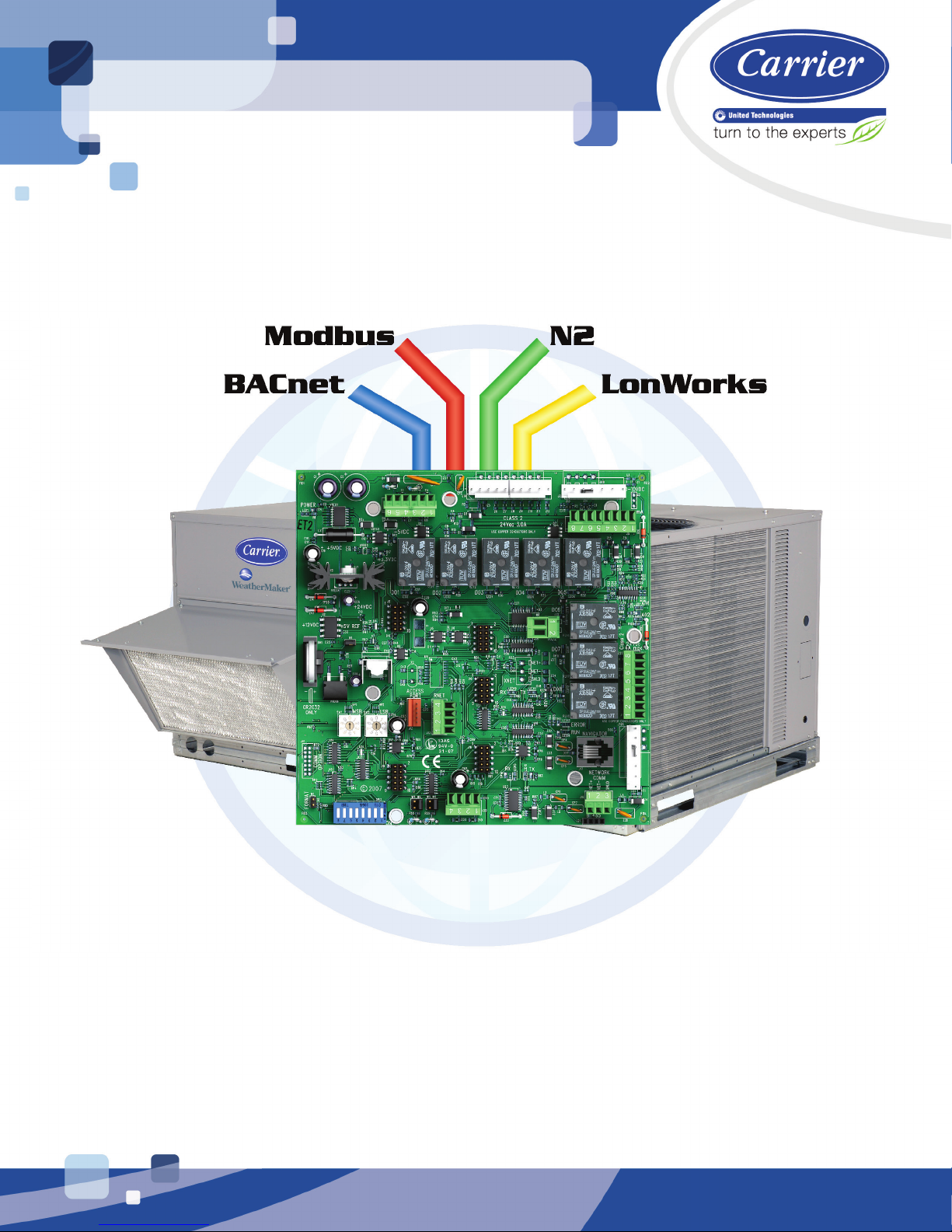
RRTTUU OOppeenn vv33
IInntteeggrraattiioonn GGuuiiddee
CARRIER CORPORATION ©2016
A member of the United Technologies Corporation family · Stock symbol UTX · Catalog No. 11-808-521-01 · 2/22/2016
Page 2

www.hvacpartners.com
Document revision history
Verify that you have the most current version of this document from
or your local Carrier
office.
Important changes are listed in
at the end of this document.
CARRIER CORPORATION ©2016. All rights reserved throughout the world. i-Vu is a registered trademark of Carrier
Corporation. BACnet is a registered trademark of ASHRAE. All other trademarks are the property of their respective
owners.
Page 3

Introduction .................................................................................................................................................................. 1
Wiring inputs and outputs ........................................................................................................................................... 4
Communications wiring .............................................................................................................................................. 6
Start-up ....................................................................................................................................................................... 17
Sequence of Operation ............................................................................................................................................. 18
Troubleshooting ......................................................................................................................................................... 32
Compliance ................................................................................................................................................................ 34
Contents
What is the RTU Open controller? ...................................................................................................................... 1
Safety considerations & handling warning ....................................................................................................... 3
Protocol overview .................................................................................................................................................. 6
BACnet MS/TP ...................................................................................................................................................... 7
To set up the RTU Open for BACnet MS/TP ......................................................................................... 7
Troubleshooting BACnet MS/TP ........................................................................................................... 8
Modbus ................................................................................................................................................................... 9
To set up the RTU Open for Modbus .................................................................................................... 9
Troubleshooting Modbus .................................................................................................................... 11
Johnson N2 ......................................................................................................................................................... 12
To set up the RTU Open for N2 ........................................................................................................... 12
Troubleshooting N2 ............................................................................................................................. 13
LonWorks ............................................................................................................................................................ 14
To set up the RTU Open for the LonWorks Option Card (Part #LON-OC) ......................................... 14
Commissioning the controller for LonWorks communication ........................................................... 15
Troubleshooting LonWorks ................................................................................................................. 16
Occupancy ........................................................................................................................................................... 18
Supply fan ........................................................................................................................................................... 19
Cooling ................................................................................................................................................................. 19
Economizer ......................................................................................................................................................... 20
Power Exhaust .................................................................................................................................................... 21
Pre-Occupancy Purge ........................................................................................................................................ 21
Unoccupied Free Cooling .................................................................................................................................. 21
Optimal Start ...................................................................................................................................................... 22
Enthalpy control ................................................................................................................................................. 23
Indoor Air CO2 .................................................................................................................................................... 23
Heating ................................................................................................................................................................ 24
Heat Pump operation ........................................................................................................................................ 24
Dehumidification ............................................................................................................................................... 25
Demand Limiting ............................................................................................................................................... 25
Door switch ......................................................................................................................................................... 25
Remote Occupancy ........................................................................................................................................... 26
Fire Shutdown .................................................................................................................................................... 26
Compressor Safety ............................................................................................................................................ 26
Fan Status ........................................................................................................................................................... 26
Filter status ......................................................................................................................................................... 27
Alarms ................................................................................................................................................................. 27
Linkage ................................................................................................................................................................ 29
Air source mode determination....................................................................................................................... 31
LED's .................................................................................................................................................................... 32
FCC Compliance ................................................................................................................................................. 34
CE Compliance ................................................................................................................................................... 34
BACnet Compliance........................................................................................................................................... 34
Page 4

Contents
Appendix A: Network Points List for RTU Open ...................................................................................................... 35
Appendix B: BACnet Protocol Implementation Conformance Statement ........................................................... 46
Appendix C: Modbus Protocol Implementation Conformance Statement........................................................... 47
Appendix D: Johnson N2 Protocol Implementation Conformance Statement .................................................... 49
Appendix E: LonWorks Protocol Implementation Conformance Statement ....................................................... 51
Document revision history ........................................................................................................................................ 52
Index ........................................................................................................................................................................... 53
Network points list for BACnet and Modbus ................................................................................................. 35
Network points list for N2 and LonWorks ...................................................................................................... 43
Page 5

What is the RTU Open controller?
NOTE
The RTU Open supports the following:
ZS Sensors
Third party protocols
Mixed systems
California Title 24
Equipment Touch
Introduction
The RTU Open controller (part# OPN-RTUM2) is available as an integrated component of a Carrier rooftop unit, or
as a field-installed retrofit product.
The RTU Open controller is available in both English or Metric units. The metric version has (-M) appended
to the part number. Everything in this document applies to both versions.
Its internal application programming provides optimum rooftop performance and energy efficiency. RTU Open
enables the unit to run in 100% stand-alone control mode or it can communicate to the Building Automation
System (BAS).
•
IAQ/CO2. Sensors provide:
○ Space setpoint offset adjustment
○ Pushbutton override
○ Occupancy indicator
•
following protocols:
○ BACnet
○ Modbus
○ Johnson N2
○ LonWorks
•
- 3 models are available for monitoring space temperature, space relative humidity, and space
- On-board DIP switches allow you to select the baud rate and choose one of the
- Supports CCN air terminals using Linkage to BACnet RTU Open Air Source
•
accordance with California Title 24 requirements
•
device with a 4.3 in. color LCD display that you connect to the RTU Open (driver v6.00:082 or later) to view or
change its property values, schedule equipment, view trends and alarms, and more, without having to access
the system's server.
The RTU Open’s application supports detailed color graphics, status, properties, alarms, trends, performance,
configuration, and help on the Equipment Touch. In addition, an RTU Open Startup Wizard has specific
screens to facilitate the Carrier Controls installation technician in initially configuring the RTU Open.
For more details about the Equipment Touch, see the Equipment Touch Installation and Setup Guide.
RTU Open v3 Carrier Proprietary and Confidential CARRIER CORPORATION ©2016
Integration Guide All rights reserved
1
- Includes advanced Fault Detection and Diagnostic Logic for Economizer Operation in
- Carrier Commercial Control’s user interface. The Equipment Touch is a touchscreen
Page 6
Introduction
RTU Open v3 Carrier Proprietary and Confidential CARRIER CORPORATION ©2016
Integration Guide All rights reserved
2
Page 7

Introduction
Safety considerations & handling warning
WARNING
When you handle the RTU Open:
• Do not contaminate the printed circuit board with fingerprints, moisture, or any foreign material.
• Do not touch components or leads.
• Handle the board by its edges.
• Isolate from high voltage or electrostatic discharge.
• Ensure that you are properly grounded.
RTU Open v3 Carrier Proprietary and Confidential CARRIER CORPORATION ©2016
Integration Guide All rights reserved
3
Page 8

Wiring inputs and outputs
RTU Open Inputs and Outputs Table
Channel
Number
Type Signal
Function
Part Number
Wire/Terminal
Numbers
Alternate
Terminals
Input 1
AI
4-20 mA
CO2
33ZCT55CO2 33ZCT56CO2
J4
N/A
Input 2
AI
4-20 mA
CO2
33ZCT55CO2 33ZCT56CO2
J4 -
N/A
Input 3
BI
24 Vac
N/A
J1 -
J5
Input 4
BI
24 Vac
Safety Chain *
N/A
J1
N/A
Input 5
BI
24 Vac
Field-supplied
J1
J5
Input 6
AI
10K
Supply Air Temperature
33ZCSENSAT 33ZCSENDAT
J2 - 1 & 2
N/A
Input 7
AI
10K
Outside Air Temperature
33ZCSENOAT
J2 - 3 & 2
N/A
Input 8
BI
24 Vac
Enthalpy **
33SENTHSW
J2
J5
Input 9
BI
24 Vac
Humidistat **
--HL--38MG-029
J5 - 7 & 8
N/A
Input 10
AI
10K
Space Temperature
33ZCT55SPT 33ZCT56SPT
J20 - 1 & 2
N/A
Input 11
AI
100K
Space Temperature
33ZCT56SPT 33ZCT59SPT
J20 - 3 & 4
N/A
Rnet
AI Zone Temperature
SPS / SPPL / SPP
J13
N/A
AO - 1
AO
Economizer
Economizer
Actuator-Field-supplied
J2
N/A
AO - 2
AO
0-10 Vdc or
Variable Frequency Drive
Field-supplied
J22
N/A
BO - 1
BO
N/A - Relay
Fan (G)
N/A
J1
N/A
BO - 2
BO
N/A - Relay
Heat 2 (W2) Output
N/A
J1
N/A
BO - 3
BO
N/A - Relay
Heat 1 (W1) Output
N/A
J1
N/A
BO - 4
BO
N/A - Relay
Cool 2 (Y2) Output
N/A
J1 - 7
N/A
Wiring inputs and outputs
OAQ
Space Relative Humidity
OAQ
Space Relative Humidity
Compressor Safety **2
Fan Status
Filter Status
Remote Occupancy
Door Contact
Fire Shutdown **1, 2
Fan Status
Filter Status
Remote Occupancy
Door Contact
Thermistor
33ZCSPTCO2-01
33ZCSPTCO2LCD-01
w/ 33ZCASPCO2
33ZCSENSRH-02
33ZCSPTCO2-01
33ZCSPTCO2LCD-01
w/ 33ZCASPCO2
33ZCSENSRH-02
CRSTATUS005A00
CRSTATUS005A00
Field-supplied
Field-supplied
CRSTATUS005A00
CRSTATUS005A00
Field-supplied
Field-supplied
- 5 & 6
2 & 3
2
***
- 9
- 10
***
- 5 & 6
- 3 & 4
RTU Open v3 Carrier Proprietary and Confidential CARRIER CORPORATION ©2016
Integration Guide All rights reserved
4
Thermistor
- 6 & 7
Fan Status
Filter Status
Remote Occupancy
Door Contact
Fan Status
Filter Status
Remote Occupancy
Door Contact
Thermistor
Thermistor
2-10 Vdc
Setpoint Adjust
CRSTATUS005A00
CRSTATUS005A00
Field-supplied
Field-supplied
CRSTATUS005A00
CRSTATUS005A00
Field-supplied
Field-supplied
33ZCT59SPT
- 1, 2, 3, 4
- 5 & 4
- 1 & 2
- 4
- 5
- 6
***
- 1 & 2
Page 9

Wiring inputs and outputs
Channel
Number
Type Signal
Function
Part Number
Wire/Terminal
Numbers
Alternate
Terminals
BO - 5
BO
N/A - Relay
Cool 1 (Y1) Output
N/A
J1
N/A
BO - 6
BO
N/A - Relay
Humidi-MiZer™
N/A
J11
N/A
BO - 7
BO
N/A - Relay
Reversing Valve / High
Speed Fan
N/A
J11
N/A
BO - 8
BO
N/A - Relay
Power Exhaust
N/A
J11
N/A
Legend
AI
AO
BI
BO
*
Safety Chain Feedback
Run Enabled
J1
**
Default input function
***
1
N.C. contact must be used as a primary safety device for approved fire shutdown operation. N.O. contact for monitoring only.
If a function other the default is used, do NOT connect wires from J1-x.
- Analog Input
- Digital Input
no safeties are used. See "To wire inputs and outputs" in the
Open wiring harness assembly terminations.
Parallel screw terminal at J5 (J5 - 1 = J2 - 6, J5 - 3 = J1 - 10, J5 - 5 = J1 - 2) may be used in place of the associated flying leads
at the harness (Part# OPN-RTUHRN). See "To wire inputs and outputs" in the
information.
2
- Analog Output
- Digital Output
- 24 Vac required at this wire to provide
- 8
- 7 & 8
- 5 & 6
- 2 & 3
status. Provide a jumper from J1 - 1 to
RTU Open Installation Guide for additional information on the RTU
RTU Open Installation Guide for additional
- 9 if
RTU Open v3 Carrier Proprietary and Confidential CARRIER CORPORATION ©2016
Integration Guide All rights reserved
5
Page 10

Communications wiring
Protocol overview
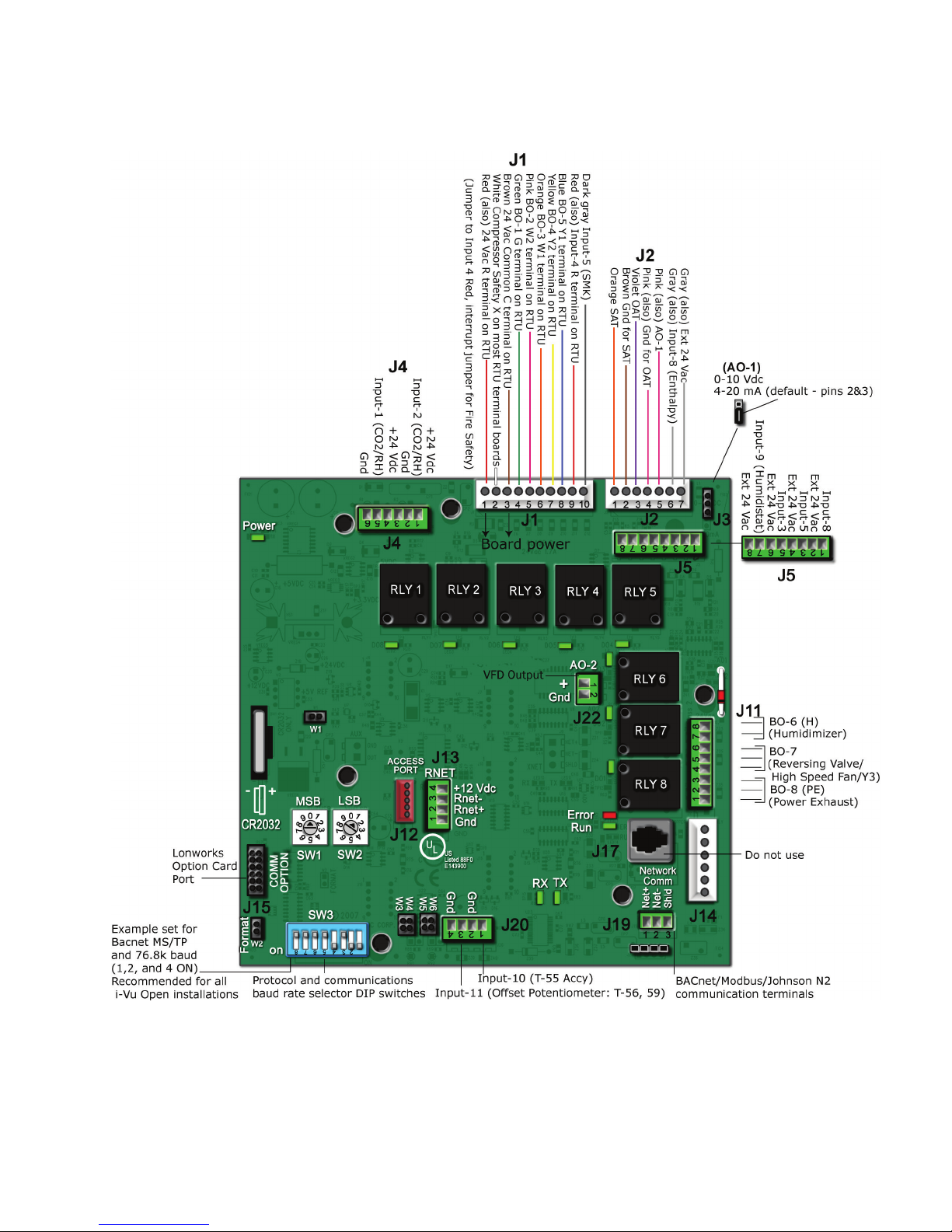
SW3
MSB
SW1
LSB (SW2
J19
J15
NOTES
MSB (SW1
LSB (SW2
J15
SW3 Switch Settings Table
Protocol Selection
Baud Rate
Protocol
DS8
DS7
DS6
DS5
DS4
DS3
DS2
DS1
BACnet MS/TP
Modbus
N2
Lonworks
Baud Selection Table
Baud Rate
SW3/DS2
SW3/DS1
9,600
19,200
38,400
76,800
Communications wiring
Protocols are the communication languages spoken by the control devices. The main purpose of a protocol is to
communicate information in the most efficient method possible. Different protocols exist to provide specific
information for different applications.
In the BAS application, many different protocols are used, depending on manufacturer. Different protocols do not
change the function of the controller, but they typically require the owner to change systems or components in
order to change from one protocol to another. The RTU Open is an effective solution to minimize the amount of
controllers that you may need to change in order to communicate with different types of protocols.
You can set the controller to communicate 1 of 4 different protocols:
• BACnet MS/TP (page 7)
• Modbus (page 9)
• N2 (page 12)
• LonWorks (page 14)
The default setting is BACnet MS/TP. Switch 3 (
(
) and
) set the board’s network address. See table below for specific switch settings. The third
party connects to the controller through port
LonWorks Option Card.
• Changing protocol requires no programming or point assignment by the installer or operator.
) on the board sets protocol and baud rate. Switches
for BACnet MS/TP, Modbus, and N2, and through
for the
• Power must be cycled after changing the
Card to
.
) -
) settings or connecting the LonWorks Option
Master Unused Off Off Off On Off Select Baud Select Baud
(Default)
Slave Unused Off Off On On Off Select Baud Select Baud
Slave Unused Off Off Off On On Off Off
Unused On On Off On Off Off On
Off Off
On Off
Off On
(Default) On On
RTU Open v3 Carrier Proprietary and Confidential CARRIER CORPORATION ©2016
Integration Guide All rights reserved
6
Page 11

Communications wiring
BACnet MS/TP
To set up the RTU Open for BACnet MS/TP
NOTE
off
NOTE
MSB (SW1
LSB (SW2
MSB (SW1
LSB (SW2
NOTE
EXAMPLE
MSB (SW1
LSB (SW2
SW3
DS1
DS2
NOTE
Baud Selection Table
Baud Rate
SW3/DS2
SW3/DS1
9,600
19,200
38,400
76,800
SW3
DS3
DS6
DS7
DS8
SW3 Protocol Switch Settings for MS/TP
DS8 DS7 DS6 DS5 DS4 DS3
Refer to Appendix B (page 46) for the Protocol Implementation Conformance Statement, or download the latest
from BACnet International http://www.bacnetinternational.net/catalog/index.php?m=28.
This controller counts as a full load on the MS/TP bus.
1 Turn
2 Using the rotary switches
the RTU Open's power.
Changes made to the switches when the controller is on will not take effect until the power is cycled!
Set the
Valid addresses are 01-99.
The rotary switches also determine the BACnet device instance of the controller on the BACnet
network. The BACnet device instance is automatically generated based on the scheme 16101xx, where “16”
is the BACnet vendor ID for Carrier Corporation, and xx equals the rotary switch address.
and the arrow on the
generated as 1610101.
To set the controller’s MS/TP MAC address to 01, point the arrow on the
) switch to the tens digit of the address, and set the
) and
) switch to 1. Internally, the BACnet device instance is automatically
), set a unique MS/TP MAC address for the RTU Open.
) switch to the ones digit.
) switch to 0
3 Set the
4 Set
5 Leave
Comm Selector DIP switches
19.2k, 38.4k, or 76.8k bps).
Use the same baud rate and communication settings for all controllers on the network segment. The
RTU Open is fixed at 8 data bits, No Parity, and 1 Stop bit for this protocol's communications.
Off Off
On Off
Off On
On On
Comm Selector DIP switches
and
in the OFF position. These switches are not applicable to MS/TP.
and
for the appropriate communications speed (9600,
through
for BACnet MS/TP. See table and example below.
Off Off Off Off On Off
RTU Open v3 Carrier Proprietary and Confidential CARRIER CORPORATION ©2016
Integration Guide All rights reserved
7
Page 12
Communications wiring
J19
Net+, Net-
SHLD
Wire specifications
NOTE
Troubleshooting BACnet MS/TP
Check the following to troubleshoot your RTU Open:
DS3 - DS6
Network Communications
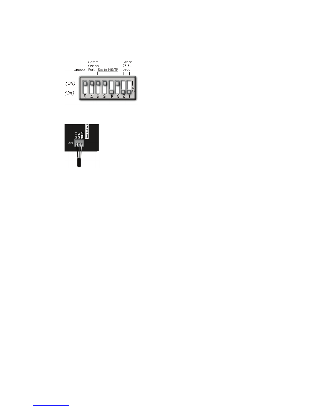
The following example shows the DIP switches set for 76.8k (Carrier default), and MS/TP.
6 Connect the MS/TP network to the controller's
port. Connect to
, and
.
○ A dedicated 22 AWG shielded twisted pair wire (EIA 485)
○ Maximum wire length 2000 feet (610 meters) or 32 nodes
○ Devices should be daisy-chained and not star-wired
○ Attach the drain/shield wire to both ends of the network segment and through every controller
Use the same polarity throughout the network segment.
7 Turn on the RTU Open's power.
1 Verify that the BAS and controller are both set to speak the BACnet MS/TP protocol on the Comm Selector
DIP switches
2 Verify that the BAS and the controller are both set for the same baud rate:
○ Baud rate DIP switches DS2 and DS1
○ Obtain a Modstat of the controller. Scroll to the bottom of the page to
the active protocol and baud rate.
3 Verify that the BAS is configured to speak 2-wire EIA-485 to the controller. The BAS may have to configure
jumper or DIP switches on their end.
4 Verify that the BAS and the controller have the same communication settings (8 data bits, No Parity, and 1
stop bit).
5 Verify proper connection wiring between the BAS and the controller.
6 Verify that the controller has a unique MAC address on the MS/TP bus. The controller’s MS/TP MAC address
is set by its rotary address switches.
RTU Open v3 Carrier Proprietary and Confidential CARRIER CORPORATION ©2016
Integration Guide All rights reserved
8
.
to view
Page 13

Communications wiring
It may be necessary to adjust the following MS/TP protocol timing settings through the Equipment Touch device:
Max Masters
Max Info Frames
NOTES
Modbus
To set up the RTU Open for Modbus
off
NOTE
MSB (SW1
LSB (SW2
7 Verify that the BAS is reading or writing to the proper BACnet objects in the controller. Refer to Appendix A for
the points list for the controller.
8 Verify that the BAS is sending his requests to the proper MS/TP MAC address of our controller.
9 Present the BAS company with a copy of the controller’s BACnet PICS so that they know which BACnet
commands are supported. The PIC statements are updated regularly. Please refer to the BACnet website
http://www.bacnetinternational.net/catalog/index.php?m=28 for the latest information. In certain
situations, it may be necessary to adjust the MS/TP Protocol timing settings through the Equipment Touch
device.
- defines the highest MS/TP Master MAC address on the MS/TP network.
For example, if there are 3 master nodes on an MS/TP network, and their MAC addresses are 1, 8, and 16, then
Max Masters would be set to 16 (since this is the highest MS/TP MAC address on the network).
This property optimizes MS/TP network communications by preventing token passes and “poll for master”
requests to non-existent Master nodes.
In the above example, MAC address 16 knows to pass the token back to MAC address 1, instead of counting up to
MAC address 127. Each MS/TP master node on the network must have their Max Masters set to this same value.
The default is 127.
- defines the maximum number of responses that will be sent when the RTU Open receives the
token. Any positive integer is a valid number. The default is 10 and should be ideal for the majority of applications.
In cases where the RTU Open is the target of many requests, this number could be increased as high as 100 or
200.
• MS/TP networks can be comprised of both master and slave nodes. Valid MAC addresses for master nodes
are 0 – 127 and valid addresses for Slave nodes are 0 - 254.
• If the third party attempts to communicate to the controller but does not get a response, make sure the
controller is set as a BACnet MS/TP (m) master. The BACnet software asks the controllers, “Who Is?” This is
to auto-locate devices on the network. Only controllers set as masters will answer this request.
• See Appendix A (page 35) for Points Mapping tables.
Refer to Appendix C (page 47) for the Modbus Protocol Implementation Conformance Statement (PICS).
1 Turn
2 Using the rotary switches, set a unique Modbus slave address for the RTU Open. Set the
RTU Open v3 Carrier Proprietary and Confidential CARRIER CORPORATION ©2016
Integration Guide All rights reserved
9
the RTU Open's power.
Changes made to the switches when the controller is on will not take effect until the power is cycled!
the tens digit of the address, and set the
are 01-99.
) switch to
) switch to the ones digit. Valid Modbus slave addresses
Page 14
Communications wiring
EXAMPLE
MSB (SW1
LSB (SW2
SW3
DS1
DS2
NOTE
Baud Selection Table
Baud Rate
SW3/DS2
SW3/DS1
9,600
19,200
38,400
76,800
SW3
DS3
DS6
DS7
DS8
SW3 Protocol Switch Settings for Modbus
DS8 DS7 DS6 DS5 DS4 DS3
J19
Net+, Net-
SHLD
and the arrow on the
To set the controller's Modbus slave address to 01, point the arrow on the
) switch to 1.
3 Set the
Comm Selector DIP switches
and
for the appropriate communications speed (9600,
19.2k, 38.4k, or 76.8k bps).
Use the same baud rate and communication settings for all controllers on the network segment. The
RTU Open is fixed at 8 data bits, No Parity, and 1 Stop bit for this protocol's communications.
Off Off
On Off
Off On
On On
through
for Modbus. See example below.
4 Set
5 Leave
Comm Selector DIP switches
and
in the OFF position. These switches are not applicable to Modbus.
) switch to 0
Off Off Off On On Off
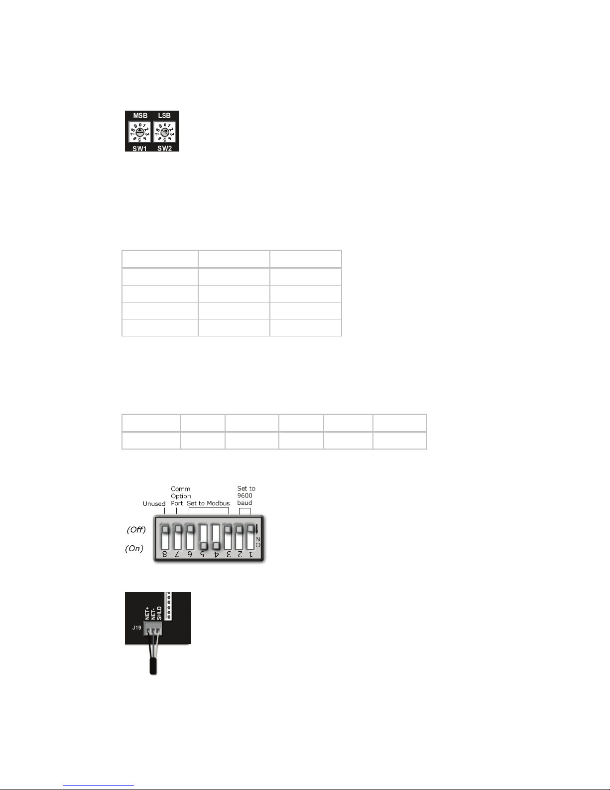
The following example shows the DIP switches set for 9600 baud and Modbus.
6 Connect the Modbus EIA-485 network to the RTU Open's
port. Connect to
, and
.
RTU Open v3 Carrier Proprietary and Confidential CARRIER CORPORATION ©2016
Integration Guide All rights reserved
10
Page 15

Communications wiring
Wire specifications
NOTE
Troubleshooting Modbus
Check the following to troubleshoot your RTU Open:
DS3 - DS6
Network Communications
NOTES
Modbus Exception Codes that might be returned from this controller
Codes
Name
Description
○ A dedicated 22 AWG shielded twisted pair wire (EIA 485)
○ Maximum wire length 2000 feet (610 meters) or 32 nodes
○ Devices should be daisy-chained and not star-wired
○ Attach the drain/shield wire to both ends of the network segment and through every controller
Use the same polarity throughout the network segment.
7 Turn on the RTU Open's power.
1 Verify that the BAS and controller are both set to speak the Modbus RTU protocol on the Comm Selector DIP
switches
2 Verify that the BAS and the controller are both set for the same baud rate:
○ Baud rate DIP switches DS2 and DS1
○ Obtain a Modstat of the controller. Scroll to the bottom of the page to
3 Verify that the BAS is configured to speak 2-wire EIA-485 to the controller. The BAS may have to configure
jumper or DIP switches on their end.
4 Verify that the BAS and the controller have the same communication settings (8 data bits, No Parity, and 1
stop bit).
5 Verify proper connection wiring between the BAS and the controller.
6 Verify that the rotary address switches are set for the controller's unique slave address.
7 BAS must be reading or writing to the proper point addresses on the controller.
8 BAS is sending requests to the proper slave address of the controller.
• Refer to Appendix A (page 35) for the Network Points list.
.
the active protocol and baud rate.
to view
• Refer to Appendix C (page 47) for the Protocol Implementation Conformance Statement.
01 Illegal Function The Modbus function code used in the query is not
02 Illegal Data
Address
04 Slave Device
Failure
RTU Open v3 Carrier Proprietary and Confidential CARRIER CORPORATION ©2016
Integration Guide All rights reserved
11
supported by the controller.
The register address used in the query is not supported
by the controller.
The Modbus Master has attempted to write to a nonexistent register or a read-only register in the
controller.
Page 16
Communications wiring
Johnson N2
To set up the RTU Open for N2
off
NOTE
MSB (SW1
LSB (SW2
EXAMPLE
MSB (SW1
LSB (SW1
DS1
DS2
NOTE
SW3
DS3
DS6
DS7
DS8
SW3 Protocol Switch Settings for N2
DS8 DS7 DS6 DS5 DS4 DS3
J19
Net+, Net-
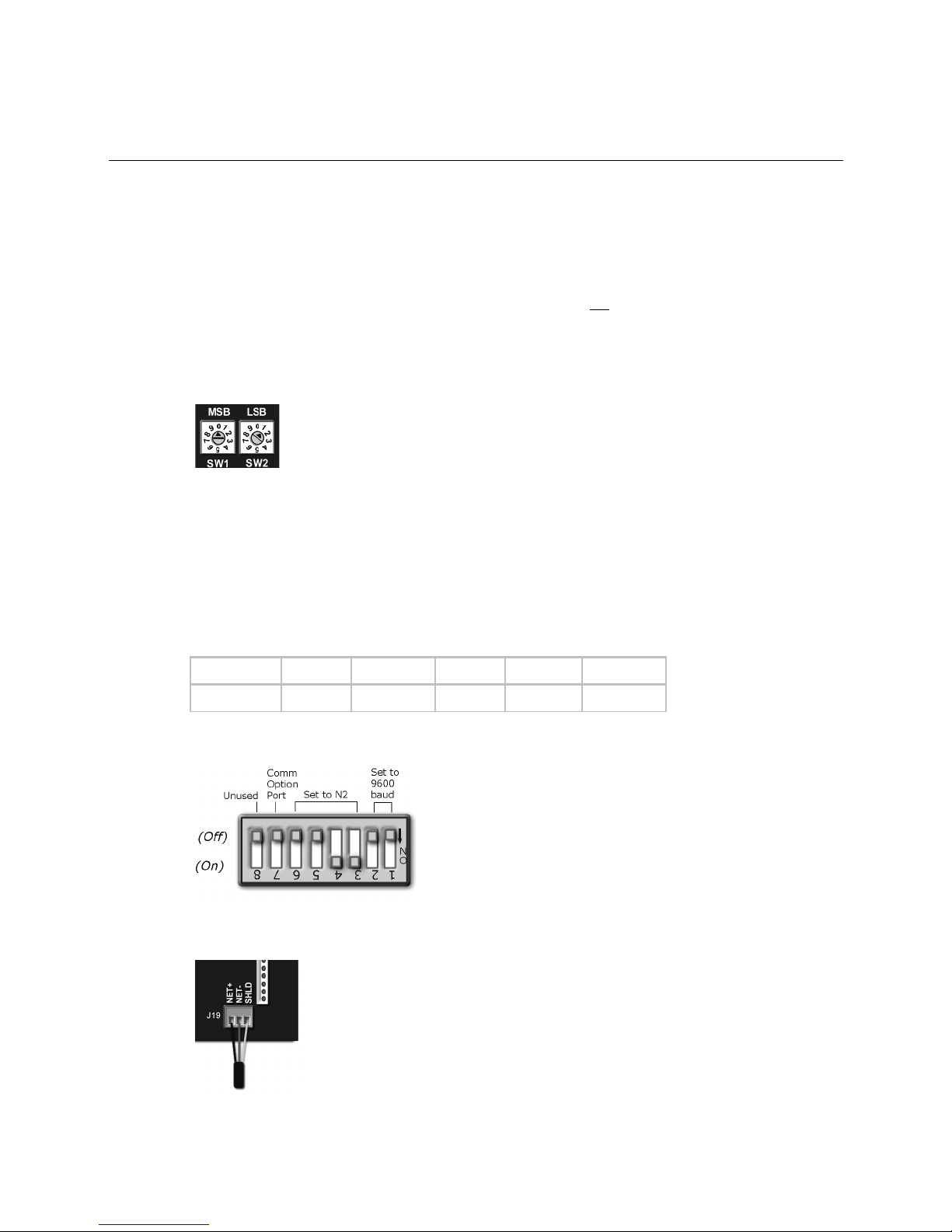
SHLD
Refer to Appendix D (page 49) for the N2 Protocol Implementation Conformance Statement (PICS).
1 Turn
2 Using the rotary switches, set a unique N2 slave address for the RTU Open. Set the
3 Set the Comm Selector DIP switches
4 Set
5 Leave
the RTU Open's power.
Changes made to the switches when the controller is on will not take effect until the power is cycled!
tens digit of the address, and set the
the
RTU Open is fixed at 9600 baud, 8 data bits, No Parity, and 1 Stop bit.
To set the N2 slave address to 01, point the arrow on the
Use the same baud rate and communication settings for all controllers on the network segment. The
) switch to 1.
Comm Selector DIP switches
and
in the OFF position. These switches are not applicable to N2.
) switch to the ones digit. Valid N2 slave addresses are 01-99.
and
through
for the 9600 baud.
for N2. See example below.
) switch to 0 and the arrow on
) switch to the
Off Off Off Off On On
The following example shows the DIP switches set for 9600 baud and N2.
6 Connect the N2 EIA-485 network to the controller's
RTU Open v3 Carrier Proprietary and Confidential CARRIER CORPORATION ©2016
Integration Guide All rights reserved
12
port. Connect to
, and
.
Page 17

Communications wiring
Wire specifications
NOTE
Troubleshooting N2
Check the following to troubleshoot your RTU Open:
DS3 -
DS6
Network Communications
NOTES
○ A dedicated 22 AWG shielded twisted pair wire (EIA 485)
○ Maximum wire length 2000 feet (610 meters) or 32 nodes
○ Devices should be daisy-chained and not star-wired
○ Attach the drain/shield wire to both ends of the network segment and through every controller
Use the same polarity throughout the network segment.
7 Turn on the RTU Open's power.
1 Verify that the BAS and controller are both set to speak N2 protocol on the Comm Selector DIP switches
.
2 Verify that the BAS and the controller are both set for the same baud rate:
○ 9600 for N2
○ Baud rate DIP switches DS2 and DS1
○ Obtain a Modstat of the controller. Scroll to the bottom of the page to
to view
the active protocol and baud rate.
3 Verify that the BAS is configured to speak 2-wire EIA-485 to the controller. The BAS may have to configure
jumper or DIP switches on their end.
4 Verify that the BAS and the controller have the same communication settings (8 data bits, No Parity, and 1
stop bit).
5 Verify proper connection wiring between the BAS and the controller.
6 Verify that the rotary address switches are set for the controller's unique slave address.
7 BAS must be reading or writing to the proper point addresses on the controller.
8 BAS is sending requests to the proper slave address of the controller.
• Refer to Appendix A (page 35) for the Network Points list.
• Refer to Appendix D (page 49) for the Protocol Implementation Conformance Statement.
RTU Open v3 Carrier Proprietary and Confidential CARRIER CORPORATION ©2016
Integration Guide All rights reserved
13
Page 18
Communications wiring
LonWorks
Ensure that you are properly grounded.
To set up the RTU Open for the LonWorks Option Card (Part #LON-OC)
off
NOTES
DS1
DS2
SW3
DS3
DS6
SW3
DS7
SW3
DS8
SW3
SW3 Protocol Switch Settings for LonWorks
DS8 DS7 DS6 DS5 DS4 DS3
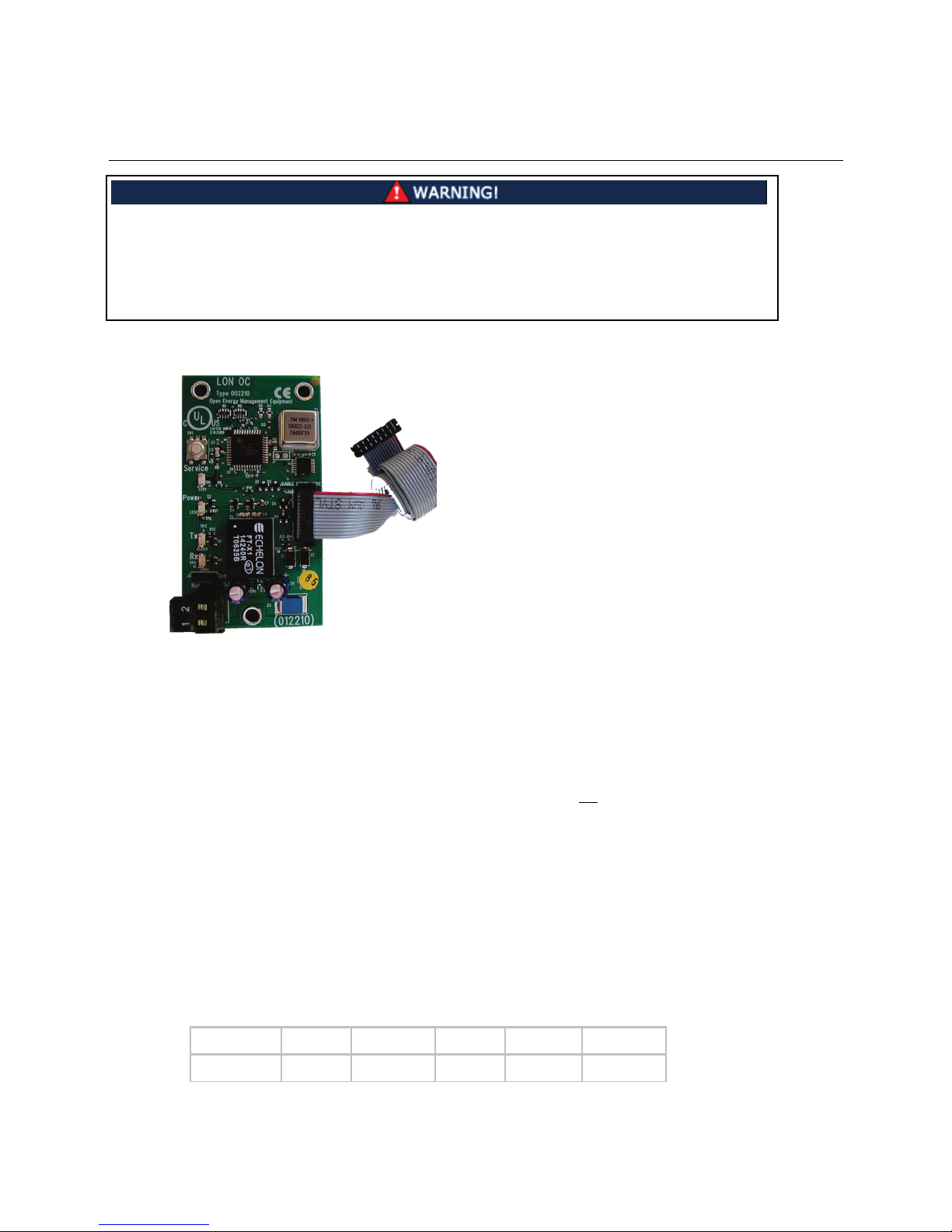
When you handle the LonWorks Option Card:
• Do not contaminate the printed circuit board with fingerprints, moisture, or any foreign material.
• Do not touch components or leads.
• Handle the board by its edges.
• Isolate from high voltage or electrostatic discharge.
•
Refer to Appendix E (page 51) for the LonWorks Protocol Implementation Conformance Statement (PICS).
1 Turn
2 Set the Comm Selector DIP switches
3 Set the Comm Selector DIP switches
4 Set the Comm Selector DIP switch
5 Leave Comm Selector DIP switch
the RTU Open's power.
○ Changes made to the switches when the controller is on will not take effect until the power has been
cycled!
○ The controller’s rotary address switches are not used when the LON-OC is installed. That’s because each
LON-OC has a 48-bit Neuron ID that makes it unique on the LonWorks network.
and
on
for 38.4k Communications speed. This is the
speed at which the LON-OC speaks to the RTU Open. It is fixed at 38.4k.
on
on
through
on
for LonWorks. See example below.
to the ON position to enable the LON-OC.
in the OFF position since it is not used.
Off On On Off On Off
RTU Open v3 Carrier Proprietary and Confidential CARRIER CORPORATION ©2016
Integration Guide All rights reserved
14
Page 19
Communications wiring
J15
CAUTION!
OFF
Net
NOTE
Net
polarity insensitive
Commissioning the controller for LonWorks communication
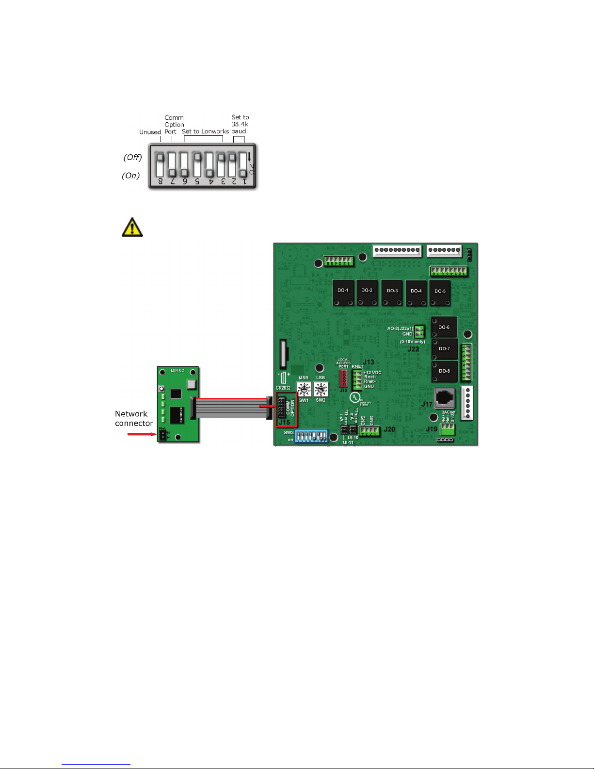
The following example shows the DIP switches set for 38.4k baud and the LON-OC enabled.
6 Plug the LON-OC's ribbon cable into Comm Option Port
The controller must be
before being connected.
on the controller. See illustration below.
7 Connect the LonWorks network to the LON-OC via the 2-pin
The 2-pin
type is
port provides TP/FT-10 channel compatibility. The TP/FT-10 or "Free Topology" network
. Use 24 to 16 AWG twisted pair wire.
port.
8 Turn on the RTU Open's power.
9 Commission the controller for LonWorks communication. See instructions below.
Before a device can communicate on a LonWorks network, it must be commissioned. Commissioning allows the
system integrator to associate the device hardware with the LonWorks system’s network layout diagram. This is
done using the device’s unique Neuron ID.
A network management tool such as Echelon’s LonMaker is used to commission each device, as well as, to assign
addressing. Specific instructions regarding the commissioning of LonWorks devices should be obtained from
documentation supplied with the LonWorks Network Management Tool.
RTU Open v3 Carrier Proprietary and Confidential CARRIER CORPORATION ©2016
Integration Guide All rights reserved
15
Page 20

Communications wiring
Browse
Troubleshooting LonWorks
Check the following to troubleshoot your RTU Open:
DS3 - DS6
Network Communications
SW3
DS7
Browse
When a new device is first commissioned onto the LonWorks network, the system integrator must upload the
device’s External Interface File (XIF) information. LonWorks uses the XIF to determine the points (network
variables) that are available from a device. The RTU Open has a set of predefined network variables. These
variables can be bound or accessed by the Network Management Tool.
The
feature of the Network Management Tool allows you to read real-time values from the RTU Open. The
Network Management Tool allows you to test integration prior to binding the controller's network variables to other
LonWorks nodes.
1 Verify that the BAS and controller are both set to speak the LonWorks protocol by theComm Selector DIP
switches
.
2 Verify that the BAS and the controller are both set for the same baud rate:
○ 38.4k for LonWorks
○ Baud rate DIP switches DS2 and DS1
○ Obtain a Modstat of the controller. Scroll to the bottom of the page to
to view
the active protocol and baud rate.
3 BAS must be reading or writing to the proper point addresses on the controller.
4 Verify that the Comm Option Port is enabled on the controller. The Comm Option Port setting must be set via
(switch
). It should be in the ON position to enable LonWorks communication.
5 Verify that controller has been properly commissioned onto the LonWorks network. See Commissioning the
controller for LonWorks communication (page 15).
6 Use the
feature of the network management tool to verify that you can communicate and get real-
time values from the controller before connecting the BAS.
7 Once you have confirmed communications with the controller using the network management tool, connect
the BAS.
8 Verify that the BAS is connected properly to the LonWorks Option Card's 2-wire TP/FT-10 Net port, which is
polarity insensitive. The BAS may have to configure jumper or DIP switches on their end to support TP/FT-10.
RTU Open v3 Carrier Proprietary and Confidential CARRIER CORPORATION ©2016
Integration Guide All rights reserved
16
Page 21

Start-up
This interface...
Provides a...
Field Assistant
Equipment Touch
i-Vu®
System Touch
CAUTION
Start-up
To start up the RTU Open, you need one of the following user interfaces to the controller. These items let you
access the controller information, read sensor values, and test the controller.
application -
Runs on a laptop that connects to controller's Local Access port
device -
2
Connects to controller's Rnet port
application
Available for BACnet systems only
device
Available for BACnet systems only
1
Temporary or permanent
interface
Permanent interface
Temporary or permanent
interface
Temporary interface
Wire to an MS/TP network connector and a 24 Vac power supply 3
1
Requires a USB Link (Part #USB-L).
2
See the Equipment Touch Installation and Setup Guide for detailed instructions.
3
See the System Touch Installation and Setup Guide for detailed instructions.
If multiple controllers share power but polarity was not maintained when they were wired, the
difference between the controller's ground and the computer's AC power ground could damage the USB Link and
the controller. If you are not sure of the wiring polarity, use a USB isolator between the computer and the USB
Link. Purchase a USB isolator online from a third-party manufacturer.
RTU Open v3 Carrier Proprietary and Confidential CARRIER CORPORATION ©2016
Integration Guide All rights reserved
17
Page 22

Sequence of Operation
Occupancy
Occupied/Unoccupied
Occupied
NOTE
Occupancy Source
Always Occupied
BACnet Schedule
BAS On/Off
Remote Occ Input
Unit Configuration
Occupancy Source
Remote Occ Input
Input Switch Configuration
Remote Occupancy
Sequence of Operation
The RTU Open supports various types of constant volume air source configurations:
• Standard heat/cool unit types with up to 2-stages of mechanical cooling and gas or electric heating
• Heat pump units utilizing a reversing valve output for heating and cooling control
• Heat pump unit (Carrier) with an OEM defrost control board
• Economizer, CO2, Demand Limiting, and RH control strategies are available for appropriately equipped units
• LC WeatherExpert™ unit with 3-stage compressor control and variable speed supply fan control.
The RTU Open may operate as part of a VVT system using Airside Linkage or as a stand-alone controller.
The RTU Open’s operation depends upon its occupancy state (
continuously in the
mode until you configure an occupancy schedule.
). The RTU Open operates
An occupancy schedule may be:
• A local schedule configured in the controller using an Equipment Touch or Field Assistant
• A BACnet schedule configured in the i-Vu® application, networked through an i-Vu® Open Router
• A BACnet or local schedule configured for subordinate VVT Zones, networked through an i-Vu® Open
Router(s) and employing Linkage
To set up occupancy schedules, see the documentation for your user interface.
A BACnet schedule, downloaded from the i-Vu® application will overwrite a local schedule that was set up
with an Equipment Touch or Field Assistant.
- the following settings determine occupancy.
Options:
•
•
•
– (default) Controller operates continuously, regardless of any configured schedule
– Uses a local BACnet occupancy schedule configured within the controller
– Occupancy is set over the network by another device or a third party BAS. Refer to the RTU
Open Integration Guide for additional instructions in communication protocols.
•
configured to receive it. You must set
– Controller monitors an input contact connected to one of the available binary inputs
to
>
to
.
and one
RTU Open v3 Carrier Proprietary and Confidential CARRIER CORPORATION ©2016
Integration Guide All rights reserved
18
Page 23

Sequence of Operation
Supply fan
Fan Control modes
Single
Two Speed
Variable Speed
Fan Modes
Auto
Continuous
Always On
Fan Off Delay
Fire Shutdown
Safety chain
Supply Air Temp Sensor
Space Temp Sensor
Supply Fan Status
Supply Fan Alarm Service Timer
Cooling
Outdoor Air Temperature
Cooling Lockout Temperature
Supply Air Temperature
Space Temperature
The RTU Open supply fan may be configured for 1 of 3
•
- The fan operates at one speed only and provides on/off operation
•
- The fan operates at 1 of 2 speeds depending on the mode of operation and load conditions.
:
During fan only or single stage cooling, the fan operates at low speed. During heating, second stage cooling,
dehumidification, or if maximum economizer operation is required, the fan operates at high speed.
•
- The fan operates at a variable speed to meet the load conditions and SAT safety
requirements to provide maximum energy savings by minimizing fan horsepower consumption. Fan speed is
NOT controlled by static pressure.
The RTU Open supply fan may be configured for 1 of 3
•
- The fan cycles on/off in conjunction with heating or cooling
•
- The fan runs continuously during occupancy and intermittently during unoccupied periods with
:
heating or cooling
•
- The fan runs continuously regardless of occupancy or calls for heating and cooling
Occupancy can be determined by Linkage, BACnet schedules, BAS schedules, or in response to a remote
occupancy switch.
A
allows the supply fan to continue operating after heating or cooling stops.
If the following alarms are active, the fan turns off immediately, regardless of the occupancy state or demand:
•
•
•
•
alarm
alarm
The RTU Open does not include smoke-control functions such as smoke-purge, zone-pressurization, or smokeventilation.
The RTU Open may be configured to accept a
input to provide proof the supply fan is operating.
When enabled, a loss or lack of fan status will stop heating and cooling operation.
A
function is available to track the number of supply fan run hours and generate
an alarm when the accumulated runtime exceeds the set threshold.
The RTU Open's application and configuration determines the specific cooling sequence. The RTU Open can
control up to 2 stages of cooling with an additional output for a reversing valve (heat pump applications). The
number of stages is configurable or is defined by unit type.
The following conditions must be true for the cooling algorithm to operate:
•
• The indoor fan is on
• The unit has a valid
• The unit has a valid
RTU Open v3 Carrier Proprietary and Confidential CARRIER CORPORATION ©2016
Integration Guide All rights reserved
19
, if valid, is greater than the
input
input
setpoint
Page 24

Sequence of Operation
Minimum Cooling SAT
Effective
Cooling Setpoint
Space Temperature
Effective Occupied Cooling Setpoint
Effective Unoccupied Cooling Setpoint
Minimum Cooling SAT Setpoint
Supply Air Temperature
Minimum Cooling SAT Setpoint
Compressor Service Alarm Timer
Economizer
Outdoor Air Temperature
Space Temperature
Economizer High OAT
Lockout Temp
Supply Air Temperature
Space Temperature
Vent Dmpr Pos / DCV Min Pos
Low Fan Econ Min Pos
Minimum Cooling
SAT
• Heat mode is not active and the 5-minute time guard between modes has expired
• Economizer is unavailable, or if the Economizer is active, mechanical cooling is available if the economizer is
open > 90% for at least 7.5 minutes, the SAT > [
+ 0.5 °F (.27 °C)].
+ 5 °F (2.7 °)] and SPT > [
The cooling relays are controlled by the Cooling Control PID Loop and Cooling Capacity algorithm. They calculate
the desired number of stages needed to satisfy the space by comparing the
•
•
when occupied
when unoccupied
to the:
When the cooling algorithm preconditions have been met, the compressors are energized in stages, as applicable.
Anti-recycle timers are employed to protect the equipment from short-cycling. There are fixed 3 minute minimum
on-times, and 5 minute off-times for each compressor output.
During compressor operation, the RTU Open may reduce the number of active stages if the rooftop supply air
temperature falls below the
started again after the normal time-guard period has expired, if the
the
. A compressor staged off in this fashion may be
has increased above
.
functions are available (1 for each stage of compression). This function tracks
the number of compressor run hours and generates an alarm when the accumulated runtime exceeds the
threshold set by the adjustable compressor service alarm timers.
The RTU Open provides an analog economizer output for rooftop units with economizer dampers. Economizer
dampers may be used to provide indoor air quality control and free cooling when outside air conditions are
suitable.
The following conditions must be true for economizer operation:
• The
• The indoor fan is on
• The unit has a valid
• The unit has a valid
If the RTU Open is configured for VFD or 2-speed fan, the economizer minimum position is adjusted to provide a
constant amount of outdoor air. If the fan is on high speed or is configured for single-speed fan, the economizer
minimum position will be set to the
fan, and the fan is on low speed, the economizer minimum position will be set to the
If all preceding conditions are true, the economizer PID loop modulates the damper between the minimum
position and 100% open..
During economizer operation, the economizer position is reduced as the SAT falls below the
The RTU Open provides FDD (Fault Detection and Diagnostics) for economizer operation in compliance with
California Title 24. The FDD logic will detect an economizer that fails to close, fails to open, is stuck fully open, and
fails to fully open. Each condition will cause an Economizer Operation alarm to occur and the specific fault
condition will be displayed.
+ 5 °F (2.8 °C), but never closes below the applicable minimum position.
is less than the
setpoint
input
input
and less than the
setpoint. If it is configured for VFD or 2-speed
.
RTU Open v3 Carrier Proprietary and Confidential CARRIER CORPORATION ©2016
Integration Guide All rights reserved
20
Page 25

Sequence of Operation
Power Exhaust
Fan Control
Two Speed
Variable Speed
Power Exhaust
Setpoint
Calculated PE Setpoint
Maintenance
Continuous Occupied Exhaust
Yes
Power Exhaust
Continuous Occupied Exhaust
Power Exhaust
Calculated Power Exhaust (PE) Setpoint
Power Exhaust Setpoint
Pre-Occupancy Purge
Pre Occupancy Purge
Pre-Occupancy Purge
Enable
Economizer Exists
Yes
Purge
Time
Economizer Purge Min Pos
Pre-Occ Purge
Maintenance
Unoccupied Free Cooling
Unocc Free Cool Enable
Unocc Free Cool Enable
Enable
Economizer High OAT Lockout Temp
Enthalpy
Low
The RTU Open may enable and disable an exhaust fan, based on either the controller’s occupancy or its
economizer damper position. If the
displayed in the
If
is automatically adjusted based on the fan’s air delivery. The
section.
is
, the
is set to
or
, the
used for control is
binary output (BO-8) is energized while the RTU Open
is occupied and de-energized when unoccupied.
If
damper output exceeds the
economizer output falls below the
is No, the
binary output (BO-8) is energized when the economizer
value by a fixed hysteresis of 10%.
value. The output remains energized until the
allows the rooftop equipment with an economizer damper to use outdoor air to purge the
space of contaminants just prior to the beginning of the occupied period.
The following conditions must be true for pre-occupancy purge to operate:
•
•
set to
set to
• A local time schedule is configured
• The local time schedule is currently unoccupied and the remaining time is less than the configured
When the RTU Open schedule is unoccupied and the remaining unoccupied time is less than the purge time, the
supply fan starts. The economizer damper opens to the configured
continues to operate in this mode until the occupied start time is reached. The
the
section.
during unoccupied periods.
The following conditions must be true for unoccupied free cooling to operate:
•
allows rooftop equipment with an economizer damper to use outdoor air for free cooling
set to
. The RTU Open
state is displayed in
• The system is unoccupied
• The outside air temperature is below the
• The outside air temperature is less than the space temperature
•
(if enabled) is
RTU Open v3 Carrier Proprietary and Confidential CARRIER CORPORATION ©2016
Integration Guide All rights reserved
21
setpoint
Page 26
Sequence of Operation
Occupied Cooling Setpoint
Optimal Start
Optimal Start
Learning Adaptive Optimal Start
Properties
Equipment
Configuration
Setpoints
Optimal Start
0 (0.00
Optimal Start
NOTE
Learning Adaptive Optimal Start
NOTE
Learning Adaptive Optimal Start
Properties
Equipment
Configuration
Setpoints
When the RTU Open schedule is unoccupied and the space temperature rises at least 1 °F (.5 °C) above the
, the supply fan starts. The economizer damper opens as necessary to cool the space.
The RTU Open continues to operate in this mode until the space is satisfied or the outside air conditions are no
longer suitable for free cooling.
The RTU Open may use either of 2 different
methods.
is used for
heat pump applications and adjusts the effective setpoints to achieve the occupied setpoints by the time
scheduled occupancy begins. This prevents or minimizes the need for auxiliary heat. The Optimal Start recovery
period may begin as early as 4 hours prior to occupancy. The algorithm works by moving the unoccupied setpoints
toward the occupied setpoints. The rate at which the setpoints move is based on the outside air temperature,
design temperatures, and capacities.
The following conditions must be true for learning adaptive optimal start to operate:
• On the
page >
to 1 and must be set greater than
tab >
disables
>
>
) and less than or equal to 4.
, the default value is set
• The system is unoccupied
If the controller does not have a valid outside air temperature, then a constant of 65°F (18.3°C) is used.
This value is not adjustable.
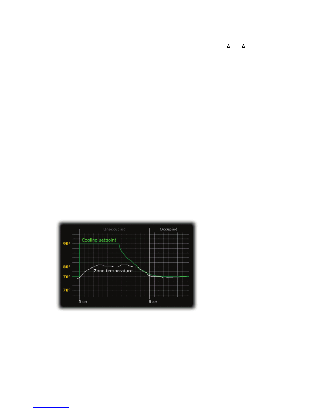
The actual equation that the controller uses to calculate
is nonlinear. An
approximation of the result is shown below.
The values in the graph below are Fahrenheit.
To change
1 In the navigation tree, select the equipment that you want to change.
2 Click
page >
RTU Open v3 Carrier Proprietary and Confidential CARRIER CORPORATION ©2016
Integration Guide All rights reserved
22
settings:
tab >
>
.
Page 27

Sequence of Operation
Temperature Compensated Optimal Start
Properties
Equipment
Configuration
Setpoints
Optimal Start
0 (0.00
Optimal Start
Properties
Equipment
Configuration
Setpoints
Heat Start K factor
Cool Start
K factor
Enthalpy control
Enthalpy
Enthalpy
Status
High
Enthalpy Status
Low
Indoor Air CO2
Indoor Air CO2
Indoor Air CO2
Indoor Air CO2
switches from unoccupied to the occupied setpoints at a calculated time prior to occupancy. This minimizes the
operation of the unit’s fan. The Optimal Start recovery period may begin as early as 4 hours prior to occupancy.
The time at which the setpoints move is based on the difference between the current space temperature and the
desired setpoint, multiplied by the "K" factor, or recovery rate, for the required mode of operation.
The following conditions must be true for Temperature Compensated Optimal Start to operate:
• On the
to 1 and must be set greater than
• The system is unoccupied
To change Temperature Compensated Optimal Start settings:
1 In the navigation tree, select the equipment that you want to change.
2 On the
. This defines the equipment’s recovery rate in minutes / deg.
You may use an enthalpy switch to indicate the suitability of outdoor air for economizer cooling. You can use either
an outdoor air or differential enthalpy switch. A differential enthalpy switch has a sensing device in both the
outdoor and return air streams. A differential enthalpy switch indicates when outside air is more suitable to be
used than the return air and is available for economizer cooling. If no enthalpy switch is configured, a network
point (Object Name: oae) is available. This point is displayed in the i-Vu® application and an Equipment Touch as
The sequence of operation for economizer cooling is the same with or without an enthalpy switch, except that an
enthalpy switch imposes one more validation on the suitability of outside air for economizer cooling. An
met.
(BACnet).
that is
that is
is a second start method used for gas or electric heating applications. It
page >
page >
tab >
tab >
disables
>
>
) and less than or equal to 4.
>
, click
, the default value is set
or
disables the economizer and the outside air damper goes to its minimum position. An
enables the economizer if a call for cooling exists and the remaining preconditions are
installing an air quality (CO2) sensor. A CO2 sensor may be terminated at the RTU Open, or a subordinate zone
controller, when part of a zoned system.
An outdoor air quality sensor may also be installed and terminated at the RTU Open, but it is not required. When
an outdoor air quality sensor is not installed, the algorithm uses 400ppm as the fixed outdoor air CO2 level.
The following conditions must be true for the
• The system is occupied
• The supply fan has been started for at least 30 seconds
• The CO2 sensor has a valid reading
RTU Open v3 Carrier Proprietary and Confidential CARRIER CORPORATION ©2016
Integration Guide All rights reserved
23
is controlled on rooftop equipment with an economizer.
algorithm to operate:
sequence is enabled by
Page 28

Sequence of Operation
Indoor Air CO2
Vent Dmpr Pos / DCV Min Pos
Indoor Air CO2
DCV
Max Vent Damper Pos
Heating
Reversing Valve
Outdoor Air Temperature
Heating Lockout Temperature
Supply Air Temperature
Space Temperature
Space Temperature
Effective Occupied Heating Setpoint
Effective Unoccupied Heating Setpoint
Supply Air
Temperature
Maximum Heating SAT
Supply Air Temperature
Maximum Heating SAT
Heat Pump operation
HP O/B
Y1/W1
HP O/B
(B)
Y2
W1
Y1/W1
W1
As the air quality within the space changes, the minimum position of the economizer damper changes, which
allows more or less outdoor air into the space, depending on the relationship of the indoor air CO2 level to the
differential setpoint.
The
position is then compared against the
algorithm calculates a minimum position value using a PID loop. The CO2 minimum damper
setpoint and the greatest value becomes the
final minimum damper position of the economizer output.
The degree to which the outside air damper may be opened by the
setpoint, which is adjustable between ten and sixty percent (10 – 60%).
algorithm is limited by the
The specific heating sequence is determined by the controller's application and configuration. The RTU Open
controls up to two stages of gas or electric heating with an additional output for a
applications).
The following conditions must be true for the heating algorithm to operate:
• The
is less than the
• The indoor fan has been ON for at least 30 seconds
setpoint
(Heat Pump
• The unit has a valid
• The unit has a valid
• Neither Cool mode nor economizer are active and the time guard between modes has expired
The heating relays are controlled by the Heating Control PID Loop and Heating Stages Capacity algorithm, which
calculate the desired number of stages to satisfy the space by comparing the
•
•
When the heating algorithm preconditions have been met, the heating is energized in stages. Anti-recycle timers
are employed to protect the equipment from short-cycling. There are fixed one minute minimum on and off times
for each heating output.
During heating operation, the RTU Open may reduce the number of active stages if the rooftop
exceeds the
again after the normal time-guard period has expired, if the
setpoint.
The RTU Open can control heat pumps
provides a separate output (BO-7) to control a reversing valve. The reversing valve control may be
configured to be energized with a call for heating
The sequence of operations are as previously described for heating and cooling except that the Y1 and
are compressor outputs, energizing mechanical heating or cooling, depending on the state of the reversing valve.
and W2 are used for auxiliary heat. Up to two stages are available.
Selection
sequences of operations are as described for Heating (page
is not used in this application.
is for heat pumps that do not require a O terminal to energize the reversing valve. The
input
input
when occupied
when unoccupied
setpoint. A heat stage turned off in this fashion may be started
and
.
, or energized with a call for cooling (O).
has decreased below the
24) and Cooling (page 19). The reversing valve output
and W2 are used for auxiliary heat. Up to two stages are available.
to the:
outputs
RTU Open v3 Carrier Proprietary and Confidential CARRIER CORPORATION ©2016
Integration Guide All rights reserved
24
Page 29

Sequence of Operation
Dehumidification
Outside Air Temperature
Cooling Lockout Temperature
Indoor Fan
Supply Air Temperature
Space Temperature
Space Relative Humidity Sensor
Humidistat
Demand Limiting
Demand Level Setpoints
Demand Level
Demand 1
Demand 2
Demand 3
Demand Limit
Level 0
Door switch
Door Contact
Door Contact
The RTU Open provides occupied and unoccupied dehumidification on units that are equipped with the Carrier
Humidi-MiZer™ option from the factory. This requires a space relative humidity sensor or a humidistat for control.
The following conditions must be true for the dehumidification control to operate:
• The
• The
has been on for at least 30 seconds
is greater than the
setpoint
• The unit has a valid
• The unit has a valid
• The unit has a valid
• Heat mode is not active and the time guard between modes has expired
When using a relative humidity sensor to control dehumidification, occupied and unoccupied dehumidification
setpoints are used.
When using a humidistat, the setpoints are not used. The humidistat indicates a high-humidity condition.
When a high indoor relative humidity condition is indicated and the above conditions are satisfied, the RTU Open
enters the dehumidification mode, energizing the Humidi-MiZer™ output.
The mode continues until the space relative humidity falls below the active setpoint by a 5% fixed Hysteresis when
a humidity sensor is used, or when there is no longer a call for dehumidification where a humidistat is used.
See the base unit / Humidi-MiZer™ operations manual for additional information.
The RTU Open may employ a demand limit strategy. Demand limiting in the RTU Open works through setpoint
expansion. The controller’s heating and cooling setpoints are expanded in steps or levels. The degree to which the
setpoints are expanded is defined by the
Each
yields a 1
(2.2
The BACnet
leaves the standard occupied and unoccupied heating and cooling setpoints in effect. Levels 1 through 3 expands
occupied heating and cooling setpoints.
°F (.5 °C) expansion,
°C) expansion.
input
input
or
input
.
(1 through 3) adjusts the heating and cooling setpoints outwards. By default,
yields a 2 °F (1.1 °C) expansion, and
variable sets the desired level of setpoint expansion in the receiving controller.
yields a 4 °F
A
mounted within the space served by a single zone rooftop. The
heating, when active (an open door or window is detected). Economizer cooling, if available, continues to operate.
The input provides a configurable alarm delay (60 second default) before heating and cooling is disabled.
RTU Open v3 Carrier Proprietary and Confidential CARRIER CORPORATION ©2016
Integration Guide All rights reserved
25
may be configured on any unused binary input. A typical application is a door or window contact
disables mechanical cooling and any
Page 30

Sequence of Operation
Remote Occupancy
Remote occupancy
Remote
Occupancy
Remote Occupancy
Occupancy Source
Remote Occ Input
Remote Occupancy
Fire Shutdown
Fire Shutdown
Compressor Safety
Compressor Safety
Compressor Safety Alarm
Properties
Equipment
Alarms
Fan Status
Fan Status
may be configured on any unused binary input channel. A typical application is a remote
contact, controlled by a third party, or an occupancy sensor to set the controller's occupied mode. The
function requires both an input configured for
to operate.
Once configured, the controller will operate in the occupied or unoccupied mode, as determined by the state of
the
shutdown contact, which, when active, immediately shuts down equipment operation.
may be configured on Binary Input 5. A typical application involves a smoke detector or fire
on most Carrier rooftop equipment.
A
equipment requires attention.
Cooling, heating, and supply fan outputs are not interrupted except where the RTU Open is configured for Heat
Pump operation. When configured for Heat Pump, and in the heating mode, a compressor safety fault will cause
the available stages of electric heating to be enabled in place of mechanical heating.
Normal operation resumes when the compressor safety circuit is de-energized.
may be configured on Binary Input 3. A compressor safety tripped indicator circuit is available
input.
is shown on
page >
tab >
, and
and indicates that the
set to
switch, current sensing relay, or other device that provides a supply fan running verification.
Enabling this function displays the supply fan’s status on the equipment graphic.
If the controller loses fan status during operation, heating and cooling are disabled, the economizer damper (if
available) is closed, and an alarm for loss of status is indicated.
If the fan status is on when the controller is commanding the fan off, the unit remains in the off state. An alarm is
generated indicating that the fan is running when it should be off.
RTU Open v3 Carrier Proprietary and Confidential CARRIER CORPORATION ©2016
Integration Guide All rights reserved
26
may be configured on any unused binary input channel. A typical application would be an airflow
Page 31

Sequence of Operation
Filter status
Filter
Filter
Dirty
Alarms
NOTE
Alarms
Properties
Equipment
Alarms
Safety Chain
Fire/Smoke Shutdown
Fire Shutdown
Gas Valve
Compressor Status
Space Temperature
Space Temperature
Alarming Temperature
Space Temperature
Alarm Limit Exceeded
Space Temperature
SPT Sensor
Shutdown
Active
status may be configured on any unused binary input channel. A typical application is a differential pressure
switch that senses the pressure drop across a filter bank.
When the pressure across the filter bank exceeds the setpoint of the differential pressure switch, the
is displayed as
on the controller graphic. An alarm indicates a dirty filter.
status
Some of the
tab >
not configured.
Examples: Low or High Temperature Cutouts (Freezestat / Firestat). This alarm indicates the safety chain circuit
(Input 4) is open. Cooling, heating, and supply fan operation stop after appropriate time guards. Normal operation
resumes when the safety chain circuit is complete.
Examples: Smoke detectors or fire shutdown relays. This alarm indicates this device (Input 5) has tripped. Cooling,
heating, and supply fan operation immediately stop. Reset fire shutdown contact to resume normal operation.
– If configured for the IGC input function, the RTU Open will compare the state of this input with the
requirement for heat (W1 or W2). If the IGC input, which detects an active flame in the gas heat section, is present
1 minute after any call for heating has ended, a gas valve failure alarm will occur, indicating a stuck gas valve.
alarm indicates the base unit's compressor safety circuit is energized. Cooling, heating, and supply fan outputs are
not interrupted except when the RTU Open is configured for Heat Pump. Normal operation resumes when the
compressor safety circuit is de-energized.
If the Heat Pump is a HP O/B Ctrl type and is in the heating mode, it will automatically replace the compressor
stage(s) with the equivalent number of auxiliary heat stages, as available.
• If it's a Carrier Heat Pump HP Y1/W1 Ctrl, there is only 1 auxiliary heat stage output and the staging is done
by the machine itself. The RTU Open control does not take any action.
• For a non-Carrier Heat Pump, when configured for 2 stages of aux heat and two compressors, Compressor 1
is replaced by Aux Heat Stage 1 and Compressor 2 is replaced by Aux Heat Stage 2.
The compressor output stays on when the safety alarm is present. For cooling, the alarm indicates the
compressors are not operating. See Heat Pump operation (page 24) for further information.
active (Alarm), displays additional values for the space temperature when the alarm condition occurred and the
alarm limit exceeded.
The following values are related to the
•
occur and is only visible when the
•
temperature and is only visible when the
actively communicating. The alarm is reset when normal SPT sensor communications resume, if power is cycled to
the controller, or if the
functions described in this section will only be visible on the
when the appropriate inputs are configured. Alarms are not initiated when the input is
page >
- You may use the RTU Open's safety chain circuit to shut down the unit for a safety condition.
- You may configure the RTU Open to accept a
contact on Input 5.
– You may configure the RTU Open to monitor the base unit’s compressor safety circuit. This
– This alarm indicates if the space temperature is outside the configured alarm limits. If
alarm:
– Displays the value of the space temperature that caused the alarm condition to
is in an alarm state.
– Displays the value of the alarm setpoint that was exceeded by the alarming
is in an alarm state.
– This alarm indicates a communication failure of a connected SPT sensor that previously had been
point is set to
.
RTU Open v3 Carrier Proprietary and Confidential CARRIER CORPORATION ©2016
Integration Guide All rights reserved
27
Page 32

Sequence of Operation
ZS Sensor
Shutdown
Active
ZS Configuration
Space Temp Sensor
Supply Air Temperature
Supply Air Temp Sensor
Indoor Air Quality
Indoor Air Quality
Indoor Air Quality Sensor
Indoor Air Quality Sensor
Space Relative Humidity
Space Relative Humidity
Space Relative Humidity Sensor
Space Relative Humidity Sensor
Filter
Filter
Input
Switch
Configuration
Unit Configuration
Filter Service Alarm Timer
Maintenance > Reset Filter Runtime Alarm
Off
Unit Configuration
Filter Service Alarm Timer
Local OAT Sensor
Outdoor Air Temp Sensor
Economizer Operation
Shutdown
Active
Economizer
Failed to Fully Open, Failed to Open, Failed to Close
Stuck Open
– This alarm indicates a communication failure of a connected ZS sensor that had previously been
actively communicating. The alarm is reset when normal ZS sensor communications resume, if power is cycled to
the controller, or if the
point is set to
.
– This alarm indicates that at least 1 ZS sensor is configured in the Sensor Binder properties
and is not communicating. The alarm is reset when the configured ZS sensor is communicating or the
configuration is changed to reflect the sensor is no longer connected to the Rnet.
– This alarm indicates an invalid sensor condition in a physically connected space
temperature sensor (SPT Sensor/T5*). Cooling, heating, and supply fan operation stop after the appropriate time
guards. Normal operation resumes when the controller detects a valid sensor.
– This alarm indicates that the supply air temperature is outside the configured alarm
limits. The alarm is reset to normal when the supply air temperature returns within the configured alarm limits
plus a 5
°F (2.7 °C) hysteresis. This alarm is inhibited until the fan has been running for 15 minutes to allow for
system stabilization after startup.
– This alarm indicates a shorted or open circuit in the SAT input. Cooling, heating, and
supply fan operation stops after the appropriate time guards. Normal operation resumes when the controller
detects a valid sensor.
– The RTU Open generates an
alarm if the CO2 level exceeds the configured
alarm limits. (This alarm is only shown when a valid indoor air quality sensor value is available).
– The RTU Open generates an
alarm if a valid sensor value is
no longer available. For locally connected sensors, the mA input at the associated channel falls below 3.5 mA or
rises above 21 mA. For network sensors, the controller is no longer receiving a value from the network. Cooling,
heating, and supply fan continue to operate. However, the controller’s IAQ control function is disabled until the
fault condition is corrected.
– The RTU Open generates a
alarm if the space humidity level
exceeds the configured low or high alarm limits. (This alarm is only shown when a valid relative humidity sensor
value is available).
– The RTU Open generates a
alarm if a valid
sensor value is no longer available. For locally connected sensors, the mA input at the associated channel falls
below 3.5 mA or rises above 21 mA. For network sensors, the controller is no longer receiving a value from the
network. Cooling, heating, and supply fan operation continues, however, the controller’s Humidi-MiZer™ binary
output is disabled until the fault condition is corrected.
– If the RTU Open is configured to monitor the filter through a hardware input switch contact, it generates a
alarm if the associated input channel detects a dirty filter condition (opposite state of the
the accumulated runtime exceeds the
). Otherwise, if no hardware switch monitoring is used, the RTU Open generates a filter alarm when
>
value (when not set to 0).
“x”
This alarm is most commonly used to indicate a filter replacement is due. Reset the filter service runtime
accumulator by setting the
each setting. Set
>
value to 0 to disable the filter service alarm
to On, back to
, and clicking OK after
function.
– This alarm indicates a shorted or open circuit in the locally connected OAT input.
– This alarm indicates a valid OAT sensor value is no longer available. An alarm
condition can occur from a failed locally connected sensor or if a network OAT value is no longer being received by
the controller. Cooling, heating, and supply fan operation continues. OAT lockouts will not operate while the sensor
is in alarm. Normal operation resumes when the controller detects a valid sensor.
24 Economizer FDD logic. Once detected, this alarm will stay active until the
– This alarm is active when an economizer fault is detected, as required by the CEC Title
input is set to
or the
fan is stopped.
above. Detected fault conditions include
– This point indicates the specific fault detected and announced by the Economizer Operation alarm
, and
.
RTU Open v3 Carrier Proprietary and Confidential CARRIER CORPORATION ©2016
Integration Guide All rights reserved
28
Page 33

Sequence of Operation
Outdoor Air Quality Sensor
Outdoor Air Quality Sensor
Setpoint Slider
Configuration
Unit Configuration
Input Configuration
Space Sensor Type
Unit Configuration
Setpoint Adjustment Range
Switch Configuration
Unit Configuration
Input
Functions 3, 5, 8,
Analog Input Configuration
Unit Configuration
Input Functions 1
2
Supply Fan Runtime
Unit
Configuration
Supply Fan Service Alarm Timer
Maintenance
Reset Supply Fan Runtime Alarm
Clear
Run
OK
Unit Configuration
Supply Fan Service Timer
0
Compressor 1 Runtime
Unit
Configuration
Compressor 1 Service Alarm Timer
Compressor 1 Runtime
Maintenance
Reset Comp 1 Runtime Alarm
Clear
Run
OK
Unit Configuration
Compressor 1 Service Timer
0
Compressor 1 Runtime
Compressor 2 Runtime
Unit
Configuration
Compressor 2 Service Alarm Time
Maintenance
Reset Comp 2 Runtime Alarm
Clear
Run
OK
Unit Configuration
Compressor 2 Service Timer
0
Service
Configuration
Compressor States
Two Stages
Airside Linkage Alarm
Linkage
– The RTU Open generates an
alarm if the mA input at the
associated channel falls below 3.5 mA or rises above 21 mA. For network sensors, the controller is no longer
receiving a value from the network. Cooling, heating, and supply fan operation continues. However, the controller’s
IAQ control function uses 400ppm as the fixed outdoor air CO
Open
– The RTU Open generates this alarm when an open circuit is detected at Input 11 and the RTU
>
>
level until the fault condition is corrected.
2
>
is set to T56. Note that only
an open circuit results in an alarm. A short across this input offsets the setpoints negatively by the amount
configured in the
- The RTU Open generates this alarm when any two of the
>
.
>
or 9 are configured identically. Neither input may work reliably and downstream control may be
affected, depending on the function duplicated. The alarm clears and normal control is restored when the input
function duplication is corrected.
and
are configured identically. Neither input may work reliably and downstream control may be affected,
- The RTU Open generates this alarm when the
>
depending on the function duplicated. The alarm clears and normal control is restored when the input function
duplication is corrected.
- The RTU Open generates a this alarm when the accumulated runtime exceeds the
>
value (when not set to 0). This alarm is most commonly used to
indicate an equipment maintenance interval is due. The supply fan runtime accumulator may be reset by setting
the
selection by clicking the
to
disables the supply fan runtime alarm function.
to indicate an equipment maintenance interval is due. The
setting the
selection by clicking the
value to
>
button when it appears. Setting
- The RTU Open generates this alarm when the accumulated runtime exceeds the
>
disables the
>
button when it appears. Setting
- The RTU Open generates this alarm when the accumulated runtime exceeds the
>
to
, and then back to
– acknowledging each
>
value (when not set to 0). This alarm is most commonly used
to
, and then back to
accumulator may be reset by
– acknowledging each
>
alarm function.
r value (when not set to 0). This alarm is most commonly used
value
to indicate an equipment maintenance interval is due. The Compressor 2 runtime accumulator may be reset by
setting the
selection by clicking the
value to
disables the Compressor 2 runtime alarm function. Note that this function is unavailable if the
>
>
button when it appears. Setting
value is not set to
to
, and then back to
>
.
– acknowledging each
- An RTU Open may act as an air source in a zoned system. Carrier systems use a function
called Linkage™ to pass data between a master zone and its air source over an MS/TP network connection. When
the RTU Open is part of a linked system, it will indicate an airside linkage alarm if it loses communications with its
linkage master or if it receives data from more than 1 master zone.
The RTU Open may serve as an air source to an Open Variable Volume Terminal (VVT) system. When the RTU Open
is part of a VVT system and the controllers are wired together to form a network, the controllers may use a method
of communication known as Linkage™. Linkage is a method by which an air source and its subordinate zone
terminals exchange data to form a coordinated HVAC system. The system's air source controller, zone controllers,
and bypass controller are linked so that their data exchange can be managed by one zone controller configured as
the VVT Master.
RTU Open v3 Carrier Proprietary and Confidential CARRIER CORPORATION ©2016
Integration Guide All rights reserved
29
Page 34

Sequence of Operation
NOTE
Linkage Callers
Linkage Callers
The VVT Master gathers the following information from the slave zone controllers:
• occupancy status
• setpoints
• zone temperature
• relative humidity
• CO
level
2
• damper position
• optimal start data
The VVT Master performs mathematical calculations and algorithms on the data and then sends the composite
information to the air source. The VVT Master receives information from the air source such as System Mode,
Supply Air Temperature, and Outside Air Temperature (if available), and passes that information to all linked
controllers.
The following paragraphs describe the interaction between the air source (RTU Open) and its subordinate
zones. Additional information regarding Open Zoned Systems may be found in the VVT Zone and VVT Bypass
Controller Installation Guides.
The VVT Master determines system operation by prioritizing heating and cooling requirements from all the zones
based on their occupancy and demand. The VVT Master scans the system continuously to determine if any zones
are occupied. Occupied zones are a higher priority than unoccupied zones. The VVT Master evaluates all the
occupied zones' heating or cooling demands and sends a request to the air source (RTU Open) for:
• Cooling, if the number of occupied zones with cooling demands exceeds the number of occupied zones with
heating demands, and the demand is greater than or equal to the number of configured
.
• Heating, if the number of occupied zones with a heating demand exceeds or is equal to the number of
.
If no zones are occupied or no occupied zones require heating or cooling, the VVT Master performs the evaluation
described above for the unoccupied zones.
The VVT Master then gathers the following information and sends it to the air source (RTU Open):
• The setpoints and zone temperature from the zone with the greatest demand for the requested air source
mode (heating or cooling). (This zone is called the reference zone.)
• The system occupancy status
• Most open damper position from any zone
• RH and CO2 values (if applicable)
The air source responds by sending the air source mode, supply air temperature, and outside air temperature. The
air source verifies the mode by comparing its supply air temperature to the space temperature received through
Linkage. See the air source documentation for operation and parameters used to verify its mode. This verification
allows the VVT system to determine if the desired air source mode is actually being provided. For example, if the
VVT Master sends a request for heating and the air source does not have heat or it’s heat has failed, the air
source's actual mode indicates that and it's current mode is sent to the zones so that they can control accordingly.
The system remains in that mode until all zones of that demand are satisfied or until the system mode reselect
timer (default 30 minutes) causes a forced re-evaluation of the system. If there is no demand for the opposite
mode, the reselect timer starts again and the current mode continues until all zones are satisfied or until the
reselect timer expires, repeating the process. If there is a demand for the opposite mode, the VVT Master sends
the reference zone's space temperature and setpoints to the air source and restarts the reselect timer. The air
source re-evaluates its demand based on the new information and goes to the Vent mode until the new mode can
be verified as described above. The amount of time this takes is determined by the air source’s operating
parameters.
The VVT Master continuously evaluates the system and updates the air source with the most current system
demand. Based on the evaluation, the reference zone can change from one zone to another. The evaluation
process continues until there is no demand from any zone or the system mode reselect timer causes a reevaluation of the system conditions.
RTU Open v3 Carrier Proprietary and Confidential CARRIER CORPORATION ©2016
Integration Guide All rights reserved
30
Page 35

Sequence of Operation
Air source mode determination
Linked air source modes
OFF
WARMUP
HEAT
FREECOOL
COOL
PRESSURIZATION
EVACUATION/SHUTDOWN
VENT
If no heating or cooling is required or the current air source mode is satisfied, the VVT Master calculates the
weighted average of the occupied and unoccupied heating and cooling setpoints. It also calculates a zone
temperature that is midway between the setpoints (occupied or unoccupied based on the system’s current
occupancy status). This information, plus the occupancy status, is sent to the air source so that its current mode is
disabled and the unit ceases heating or cooling operation. If the system is occupied, the air source fan and OA
damper, if applicable, operate to maintain proper ventilation.
– In a linked system, the air source determines its operating mode and qualifies that
mode based on its own SAT and the referenced zone's temperature. The following modes can be sent by the air
source depending on its configuration:
•
– Air source fan is off.
•
•
•
•
•
– Air source fan is on and providing first cycle of heat when changing from unoccupied to occupied.
– Air source fan is on and providing heat.
– Air source fan is on and providing cooling using economizer only.
– Air source fan is on, and cooling is provided by economizer and mechanical cooling.
– Fire-Life safety override input is active. Air source fan is on providing 100 percent
outside air. Mechanical heating and cooling may be disabled.
•
•
– Air source fan is on, economizer providing ventilation without heating or cooling, providing neutral
– Fire-Life safety override input is active. Air source fan is off.
supply air temperature.
See the air source’s Installation manual for specific operation.
RTU Open v3 Carrier Proprietary and Confidential CARRIER CORPORATION ©2016
Integration Guide All rights reserved
31
Page 36

Troubleshooting
LED's
If this LED is on...
Status is...
Power
The RTU Open has power
Rx
The RTU Open is receiving data from the network segment
Tx
The RTU Open is transmitting data over the network segment
BO#
The binary output is active
NOTE
Run
Error
If Run LED shows...
And Error LED shows...
Status is..
2 flashes per second
Off
Normal
2 flashes per second
2 flashes,
Run
Five minute auto-restart delay after
Troubleshooting
The RTU Open controller acts as an intelligent embedded thermostat to the rooftop unit, but can be monitored and
controlled from a third party network. For this reason, there are 3 distinct components for troubleshooting.
The three parts to the system are:
• The mechanical systems of the rooftop unit
• The RTU Open controller
• The third party network connected
Determining which component needs troubleshooting is the first step.
The RTU Open controller can be used to troubleshoot itself with service test, communicating LED’s, and built-in
alarms, which are discussed in the unit Controls and Troubleshooting instructions. Disconnecting the RTU Open
from the unit control inputs can be valuable in determining whether the problem is related to the unit/equipment,
the controller/equipment, or the controller/network. Generally, this should be the first step in troubleshooting
operational problems. When disconnected from the unit control inputs, simple 24V signals can be used to activate
the units G, Y1, Y2, W1, W2, etc. and verify proper unit operation. If the problem occurs without the RTU Open
connected, then the operator should begin troubleshooting the unit/equipment rather than the RTU Open or
network.
Third party network may also help in troubleshooting the controller and rooftop unit. Third party network
troubleshooting may also be required.
The LED’s indicate if the controller is speaking to the other devices on the network. The LED’s should reflect
communication traffic based on the baud rate set. The higher the baud rate, the more solid the LED’s will appear.
The LED's on the RTU Open show the status of certain functions.
If Tx is not lit, the MS/TP token is not being passed between controllers.
The
and
LED's indicate controller and network status.
alternating with
LED
system error
RTU Open v3 Carrier Proprietary and Confidential CARRIER CORPORATION ©2016
Integration Guide All rights reserved
32
Page 37

Troubleshooting
If Run LED shows...
And Error LED shows...
Status is..
2 flashes per second
3 flashes, then off
Controller has just been formatted
2 flashes per second
On
Two or more devices on this network
2 flashes per second
On
Firmware halted after frequent
5 flashes per second
Off
Firmware transfer in progress, Boot is
7 flashes per second
7 flashes per second,
Run
Ten second recovery period after
14 flashes per second
14 flashes per second, alternating with
Run
Brownout
On
On
Failure. Try the following solutions:
Replace the RTU Open.
alternating with
LED
LED
have the same network address
system errors or control programs
halted
running
brownout
• Turn the RTU Open off, then
on.
•
RTU Open v3 Carrier Proprietary and Confidential CARRIER CORPORATION ©2016
Integration Guide All rights reserved
33
Page 38
Compliance
FCC Compliance
CAUTION
CE Compliance
WARNING
BACnet Compliance
Compliance
This equipment has been tested and found to comply with the limits for a Class A digital device, pursuant to Part
15 of the FCC Rules. These limits are designed to provide reasonable protection against harmful interference
when the equipment is operated in a commercial environment. This equipment generates, uses, and can radiate
radio frequency energy and, if not installed and used in accordance with the instruction manual, may cause
harmful interference to radio communications. Operation of this equipment in a residential area is likely to cause
harmful interference in which case the user will be required to correct the interference at his own expense.
void the user’s authority to operate the equipment.
Changes or modifications not expressly approved by the responsible party for compliance could
This is a Class A product. In a domestic environment, this product may cause radio interference
in which case the user may be required to take adequate measures.
BACnet® is a registered trademark of ASHRAE. ASHRAE does not endorse, approve or test products for compliance
with ASHRAE standards. Compliance of listed products to requirements of ASHRAE Standard 135 is the
responsibility of BACnet International. BTL
®
is a registered trademark of BACnet International.
RTU Open v3 Carrier Proprietary and Confidential CARRIER CORPORATION ©2016
Integration Guide All rights reserved
34
Page 39

Appendix A: Network Points List for RTU Open
Network points list for BACnet and Modbus
BACnet
Modbus
Point Name
Point
Units
Default
BACnet Point Name
BACnet Object
Modbus Register Type
Modbus
Active Heat
Effective Cool
High Space
0=Normal
Low Space
0=Normal
Input_6
R
°F ai_6
AI:1006
Supply Fan Relay
0=Off
0=Off
Economizer
Outdoor Air
0=Normal
DCV Max Vent
Holding Register
Space
HP Rev Cycle
Holding Register
System Outdoor
Holding Register
Economizer Purge
Holding Register
Active
1=Off
12=Pre-occ Purge
Appendix A: Network Points List for RTU Open
Stages
Setpoint
Temperature
Temperature
State
Supply Fan Status R
Output
Quality Sensor
Damper Pos
Temperature Prime Variable
Lockout Temp
Air Temperature
Min Pos
Access
R heat_run AV:2003 Input Register (Float) 33
R °F eff_cl_stpt AV:3005 Input Register (Float) 55
R
R
R
R %Open econ_output AV:2022 Input Register (Float) 51
R
R/W %Open 50 iaq_dpr_max AV:9011
R °F space_temp AV:2007 Input Register (Float) 107
R/W °F -3 hp_rev_cycle_lockout AV:9004
R/W °F -999 system_oat AV:1901
R/W %Open 40 econ_purge_min AV:9029
1=Alarm
1=Alarm
1=On
1=On
1=Alarm
Value
spt_hi_alarm BV:7011 Discrete Input 35
spt_lo_alarm BV:7012 Discrete Input 39
sfan BV:2001 Discrete Input 23
sfan_status BV:1003 Discrete Input 24
oaq_fail BV:7006 Discrete Input 41
ID
(Float)
(Float)
(Float)
(Float)
Register #
47
71
119
75
Compressor
Stages
System Mode R
RTU Open v3 Carrier Proprietary and Confidential CARRIER CORPORATION ©2016
Integration Guide All rights reserved
35
R comp_run AV:2020 Input Register (Float) 31
2=Fan Only
3=Economizer
Cooling
4=Cooling
5=Heating
6=Dehumidificati
on
7=Test
8=Shutdown
9=Unocc Free
Cooling
10=Fire
Shutdown
11=IAQ Override
run_status MSV:2002
Input Register
(Signed)
1
Page 40

Appendix A: Network Points List for RTU Open
BACnet
Modbus
Point Name
Point
Units
Default
BACnet Point Name
BACnet Object
Modbus Register Type
Modbus
13=IGC Override
Supply Air
DCV Max Ctrl
Holding Register
Occ Relative
Holding Register
0=Unoccupied
1=Occupied
1=None
Holding Register
Economizer Test
R/W
%Open
0
econ_test
AV:81001
Space Relative
0=Normal
Setpoint
Effective Heat
Setpoint
Low Fan Econ Min
Holding Register
Fire / Smoke
0=Normal
0=Off
Holding Register
ZS Sensor
0=Normal
Space Relative
Outdoor Air
Cooling Lockout
Holding Register
Power Exhaust
Holding Register
1=Inactive
Holding Register
Holding Register
Compressor
0=Normal
Filter Service
Alarm Timer
Holding Register
(Float)
Indoor Air Quality
0=Normal
Heating Lockout
Holding Register
Dehumidification
R
0=Inactive
dehum
BV:2006
Discrete Input
9
Temperature
Setpoint
Humidity Setpoint
Occupancy Status R
Optimal Start
Type
Access
R °F sa_temp AV:1008 Input Register (Float) 109
R/W ppm 650 iaq_stpt_max AV:3013
R/W %rh 60 occ_dehum_stpt AV:3011
2=Temp
R/W
Compensated
3=Learning
Adaptive
Value
ID
occ_status BV:2008 Discrete Input 18
2 start_type MSV:2009
Setpoint R/W °F unocc_ht_stpt AV:3004
Humidity Sensor
Adjustment
R
1=Alarm
R °F stpt_adj AV:1006 Input Register (Float) 99
sprh_sensor_fail BV:7022 Discrete Input 45
R °F eff_ht_stpt AV:3006 Input Register (Float) 57
Pos
Shutdown
Reset Filter Alarm R/W
R/W %Open 33 econ_min_2 AV:9030
R
1=Alarm
1=On
fire_alarm BV:7007 Discrete Input 32
Inactive (0) filter_rntm_clr BV:7517 Coil 22
Setpoint R/W °F unocc_cl_stpt AV:3003
Configuration
Humidity
Temperature
Temperature
Setpoint
R
R %rh space_rh AV:1011 Input Register (Float) 103
R °F oa_temp AV:1003 Input Register (Float) 87
R/W °F 45 oat_cl_lockout AV:9002
R/W %Open 50 pexh_stpt AV:3010
BAS On / Off R/W
1=Alarm
2=Occupied
3=Unoccupied
zs_config_fail BV:7055 Discrete Input 63
1 keypad_ovrde MSV:1001
System Space AQ R/W ppm -999 system_iaq AV:1903
System Space RH R/W % -999 system_rh AV:1904
Status
R
1=Alarm
comp_alarm BV:7013 Discrete Input 30
R/W hr 600 filter_service_hrs AV:2019
(Float)
(Float)
Holding Register
(Signed)
(Float)
(Float)
(Float)
(Float)
(Float)
Holding Register
(Signed)
(Float)
(Float)
Register #
45
83
154
17
89
15
43
97
133
149
151
67
Sensor
Temperature
R
1=Alarm
R/W °F 65 oat_ht_lockout AV:9003
RTU Open v3 Carrier Proprietary and Confidential CARRIER CORPORATION ©2016
Integration Guide All rights reserved
36
iaq_sensor_fail BV:7039 Discrete Input 37
(Float)
69
Page 41

Appendix A: Network Points List for RTU Open
BACnet
Modbus
Point Name
Point
Units
Default
BACnet Point Name
BACnet Object
Modbus Register Type
Modbus
1=Active
Reversing Valve
0=Off
Password
Vent Dmpr Pos /
Holding Register
0=Clean
0=Normal
Unocc Relative
Holding Register
Holding Register
(Float)
Supply Air Temp
0=Normal
Override Time
Setpoint
0=Disable
System Space
Holding Register
Space
System Outdoor
Holding Register
Outdoor Air Temp
0=Normal
0=Normal
1=Off
5=On
Setpoint
Holding Register
0=High
Holding Register
(Float)
System Cooling
System Heating
System OAT
T5x Override
VFD Speed Test
R/W % 0
vfd_spd_test
AV:81002
0=Off
0=Off
Relay State
Protected Output
Variable
DCV Min Pos
Filter R
Safety Chain R
Humidity Setpoint
Access
R
1=On
R/W 0 ppo AV:90000
R/W %Open 20 econ_min AV:9005
1=Dirty
1=Alarm
R/W %rh 95 unocc_dehum_stpt AV:3012
Value
ID
aux_1 BV:2007 Discrete Input 20
filter_alarm BV:7017 Discrete Input 31
safety_alarm BV:7024 Discrete Input 43
Setpoint R/W °F occ_ht_stpt AV:3002
Sensor
Remaining
Adjustment
Temperature
Temperature
Offset Pot
AQ
Sensor
SPT Sensor R
R
1=Alarm
R min ovrde_time AV:2016 Input Register (Float) 93
R/W
1=Enable
R/W °F -999 system_spt AV:1902
R °F stpt_adj_offset AV:91006
R/W ppm -999 system_oaq AV:1908
R
1=Alarm
1=Alarm
loc_sat_sensor_fail BV:7020 Discrete Input 51
Active (1) stpt_adj_enable BV:1013 Coil 26
oat_fail BV:7029 Discrete Input 27
spt_sensor_fail BV:7032 Discrete Input 38
(Float)
(Float)
(Float)
(Float)
Register #
131
129
19
123
155
2=Low
Fan / Speed R
3=Med
fan_run MSV:2004
4=High
Adjustment Range
Enthalpy (BACnet) R/W
R/W °^F 5 stpt_adj_range AV:9015
1=Low
Active (1) oae BV:1901 Coil 6
Optimal Start R/W hr 1 optm_start AV:9026
Demand Level
Demand Level
Master
Duration
input_3 R
input_4 R
R cool_demand_level AV:9006
R heat_demand_level AV:9036
R °F mstr_oa_temp AV:80001
R/W hr 1 ovr_dur AV:9023
1=On
1=On
di_3 BI:1003
di_4 BI:1004
Input Register
(Signed)
(Float)
175
101
147
RTU Open v3 Carrier Proprietary and Confidential CARRIER CORPORATION ©2016
Integration Guide All rights reserved
37
Page 42

Appendix A: Network Points List for RTU Open
BACnet
Modbus
Point Name
Point
Units
Default
BACnet Point Name
BACnet Object
Modbus Register Type
Modbus
0=Off
0=Off
0=Off
0=Normal
Analog Input
0=Normal
Compressor 1
0=Normal
Compressor 1
0=Off
Compressor 1
0=Disable
Compressor 2
0=Off
Compressor 2
0=Normal
Compressor 2
Test
0=Disable
1=Enable
Compressor
0=Normal
Continuous
0=No
DCV Control
R/W Inactive (0)
dcv_enable
BV:1027
Dehumidification
0=Disable
Door Contact
0=Off
0=No
0=High
0=Off
1=On
Factory Test Relay
0=Off
Factory Test Relay
0=Off
Factory Test Relay
0=Off
Factory Test Relay
0=Off
Factory Test Relay
0=Off
Factory Test Relay
0=Off
Factory Test Relay
0=Off
Factory Test Relay
0=Off
0=Clean
Fire Shutdown
R
0=Run Enabled
firedown_status
BV:1005
input_5 R
input_8 R
input_9 R
Airside Linkage R
Configuration
Runtime
Relay State
Test
Relay State
Runtime
Safety Status
Occupied Exhaust
Access
R
R
R
R/W
R
R
R/W
R
R/W
1=On
1=On
1=On
1=Alarm
1=Alarm
1=Alarm
1=On
1=Enable
1=On
1=Alarm
1=Trouble
1=Yes
Value
ID
di_5 BI:1005
di_8 BI:1008
di_9 BI:1009
air_linkage_fail BV:7030
ai_cfg_alarm BV:7026
comp1_rntm_alarm BV:7014
comp_1 BV:2005
Inactive (0) comp1_test BV:81005
comp_2 BV:2004
comp2_rntm_alarm BV:7015
Inactive (0) comp2_test BV:81004
comp_status BV:1008
Inactive (0) occ_exh BV:9002
Register #
Test
Status
R/W
R
Economizer Exists R/W
Enthalpy Status R
Factory Test R/W
1 Control
2 Control
3 Control
4 Control
5 Control
6 Control
7 Control
8 Control
R/W
R/W
R/W
R/W
R/W
R/W
R/W
R/W
Filter Status R
1=Enable
1=On
1=Yes
1=Low
1=On
1=On
1=On
1=On
1=On
1=On
1=On
1=On
1=Dirty
Inactive (0) dehum_test BV:81006
door_contact_status BV:1010
Inactive (0) econ_exist BV:99001
enthalpy_status BV:1002
Inactive (0) fac_test_enable BV:91000
Inactive (0) relay1_fac_test BV:91001
Inactive (0) relay2_fac_test BV:91002
Inactive (0) relay3_fac_test BV:91003
Inactive (0) relay4_fac_test BV:91004
Inactive (0) relay5_fac_test BV:91005
Inactive (0) relay6_fac_test BV:91006
Inactive (0) relay7_fac_test BV:91007
Inactive (0) relay8_fac_test BV:91008
filter_status BV:1004
RTU Open v3 Carrier Proprietary and Confidential CARRIER CORPORATION ©2016
Integration Guide All rights reserved
38
Page 43

Appendix A: Network Points List for RTU Open
BACnet
Modbus
Point Name
Point
Units
Default
BACnet Point Name
BACnet Object
Modbus Register Type
Modbus
Status
1=Shutdown
0=Disable
0=Disable
Heat Stage 1
0=Off
Heat Stage 2
Relay State
0=Off
1=On
0=Electric
High Speed Fan
0=Disable
Humidistat Input
Status
0=High
1=Low
0=Off
0=Normal
Occupancy
0=Off
Power Exhaust
0=Off
Power Exhaust
0=Disable
Reset Comp 1
0=Run
Reset Comp 2
0=Run
Reset Supply Fan
0=Run
Reversing Valve
RH Control
R/W Inactive (0)
rh_enable
BV:1025
Safety Chain
0=Off
0=Unoccupied
0=Disable
0=Normal
0=Inactive
Supply Fan
0=Normal
Supply Fan in
0=Normal
Supply Fan
0=Normal
Switch
Configuration
0=Normal
1=Alarm
System is shut
0=No
0=Disable
Access
Heat 1Test R/W
Heat 2Test R/W
Relay State
R
R
Heat Type R/W
Test
R/W
R
IGC Override R
Local OAT Sensor R
Contact
Relay State
Test
Runtime Alarm
Runtime Alarm
Runtime Alarm
Output
R
R
R/W
R/W
R/W
R/W
R/W Inactive (0) rev_vlv_type BV:1026
1=Enable
1=Enable
1=On
1=Gas
1=Enable
1=Active
1=Alarm
1=On
1=On
1=Enable
1=Clear
1=Clear
1=Clear
Value
ID
Inactive (0) heat1_test BV:81003
Inactive (0) heat2_test BV:81002
heat_1 BV:2003
heat_2 BV:2002
Inactive (0) heat_type BV:99002
Inactive (0) hi_spd_test BV:81010
humstat_status BV:1006
igcovr_status BV:1022
loc_oat_sensor_fail BV:7003
occ_contact_status BV:1007
pexh BV:2010
Inactive (0) pexh_test BV:81008
Inactive (0) comp1_rntm_clr BV:7514
Inactive (0) comp2_rntm_clr BV:7515
Inactive (0) sfan_rntm_clr BV:7510
Register #
Feedback
R
Schedule R/W
Service Test R/W
Setpoint Slider R
Shutdown R/W
Failure
Hand
Runtime
R
R
R
R
down
R
Unocc Free Cool R/W
1=On
1=Occupied
1=Enable
1=Alarm
1=Active
1=Alarm
1=Alarm
1=Alarm
1=Yes
1=Enable
safety_status BV:1009
0 schedule BV:8000
Inactive (0) test_enable BV:81000
slidepot_alarm BV:7002
Inactive (0) shutdown BV:9001
sfan_fail_alarm BV:7008
sfan_hand_alarm BV:7009
sfan_rntm_alarm BV:7010
di_cfg_alarm BV:7025
shutdown_status BV:2011
Inactive (0) ntfc_ena BV:80001
RTU Open v3 Carrier Proprietary and Confidential CARRIER CORPORATION ©2016
Integration Guide All rights reserved
39
Page 44

Appendix A: Network Points List for RTU Open
BACnet
Modbus
Point Name
Point
Units
Default
BACnet Point Name
BACnet Object
Modbus Register Type
Modbus
1=Off
Compressor
1=One Stage
1=Disabled
1=Single Speed
1=Auto
1=No Sensor
1=No Sensor
1=No Function
Input 3 Switch
1=NO
1=No Function
Input 5 Switch
1=NO
1=No Function
Input 8 Switch
1=NO
1=No Function
2=HumidiStat
Access
Air Source Mode R
Stages
R/W
Equipment Status R
Fan Control R/W
Fan Mode R/W
Input 1 Function R/W
Input 2 Function R/W
2=Warmup
3=Heating
4=Cooling
5=Freecool
6=Pressure
7=Evac
8=Vent
2=Two Stages
2=Test
3=Run
2=Two Speed
3=Variable Speed
2=Continuous
3=Always On
2=IAQ Sensor
3=OAQ Sensor
4=Space RH
Sensor
2=IAQ Sensor
3=OAQ Sensor
4=Space RH
Sensor
Value
ID
link_ahu_mode MSV:2005
2 comp_stages MSV:91003
mode_status MSV:2001
3 fan_type MSV:9031
2 fan_mode MSV:9032
1 ai1_function MSV:81001
1 ai2_function MSV:81002
Register #
Input 3 Function R/W
Configuration
R/W
Input 5 Function R/W
Configuration
R/W
Input 8 Function R/W
Configuration
R/W
Input 9 Function R/W
2=Compressory
Safety
3=Fan Status
4=Filter Status
5=Remote
Occupancy
6=Door Contact
2=NC
2=Fire Shutdown
3=Fan Status
4=Filter Status
5=Remote
Occupancy
6=Door Contact
2=NC
2=Enthalpy
Switch
3=Fan Status
4=Filter Status
5=Remote
Occupancy
6=Door Contact
2=NC
2 di3_function MSV:81003
1 di3_type MSV:81013
2 di5_function MSV:81005
1 di5_type MSV:81015
2 di8_function MSV:81008
1 di8_type MSV:81018
2 di9_function MSV:81009
RTU Open v3 Carrier Proprietary and Confidential CARRIER CORPORATION ©2016
Integration Guide All rights reserved
40
Page 45

Appendix A: Network Points List for RTU Open
BACnet
Modbus
Point Name
Point
Units
Default
BACnet Point Name
BACnet Object
Modbus Register Type
Modbus
3=Fan Status
Input 9 Switch
1=NO
1=1
3=0
1=Always
Input
1=T55
1=Sensor Failure
1=Heat / Cool
0=Normal
Economizer
0=Normal
Space
zone_temp_zone_
zone_temp_override_
input_10
R
°F ai_10
AI:1010
Factory Test
Economizer High
Maximum Heating
Compressor 2
Linkage Max
Air Source Supply
Max VFD Output
R/W % 100
max_vfd_spd
AV:3026
Dehum Min VFD
R/W % 100
dehum_min_vfd
AV:3028
Access
Configuration
Number Of Heat
Stages
Occupancy
Source
R/W
R/W
R/W
Space sensor type R/W
Space Temp
Source
R
4=Filter Status
5=Remote
Occupancy
6=Door Contact
2=NC
2=2
Occupied
2=BACnet
Schedule
3=BAS On/Off
4=Remote Occ
2=T56
3=SPT Sensor
4=None
2=SPT Sensor
3=T55 / T56
4=Network
5=Airside Linkage
6=Locked Value
Value
ID
1 di9_type MSV:81019
2 heat_stages MSV:91004
1 occ_source MSV:1002
1 spt_type MSV:9001
spt_status MSV:2003
Register #
2=LC
Unit Type R/W
WeatherExpert
3=HP O/B Ctrl
ZS Temp Sensor R
Operation
Temperature
Alarm Status
4=HP Y1/W1 Ctrl
1=Alarm
R
R
1=Fault Detected
0=Normal
1=Alarm
SPT Sensor R °F
SPT Sensor R min
Analog 1 Control
OAT Lockout
Temp
SAT
Runtime
Damper Position
Air Temp
R/W % 0 ao1_fac_test AV:91001
R/W °F 75 oat_ec_lockout AV:9008
R/W °F 120 sat_ht_max AV:83004
R hr comp2_rntm AV:2018
R % link_max_dmpr AV:2611
R °F link_sat AV:2608
2 unit_type MSV:9018
zst_sensor_fail BV:7051
econ_opr BV:7054
spt_alrm_status BV:7056
temp
time_remaining
AI:1
AV:1
RTU Open v3 Carrier Proprietary and Confidential CARRIER CORPORATION ©2016
Integration Guide All rights reserved
41
Page 46

Appendix A: Network Points List for RTU Open
BACnet
Modbus
Point Name
Point
Units
Default
BACnet Point Name
BACnet Object
Modbus Register Type
Modbus
Output
Air Source
Stage 3 SAT Stpt
R/W
°F
56
stg_3_sat
AV:83010
Stage 1 SAT Stpt
R/W
°F
57
stg_1_sat
AV:83008
HP Aux Heat
input_1
R
ai_1
AI:1001
Factory Test
Compressor 2
Compressor 1
Compressor 1
Min VFD Output
R/W % 40
min_vfd_spd
AV:3027
Stage 2 SAT Stpt
R/W
°F
57
stg_2_sat
AV:83009
slidepot voltage
Filter Runtime
R
hr filter_rntm
AV:2015
Fan Off Delay
R/W
seconds
90
fan_delay_off
AV:9024
input_7
R
°F ai_7
AI:1007
input_11
R
ai_11
AI:1011
input_2
R
ai_2
AI:1002
Minimum Cooling
Power Fail Restart
Holding Register
Supply Fan
Supply Fan
Indoor Air Quality
CO2 (ppm)
Supply Fan VFD
R %
vfd_output
AV:2027
0=Normal
Supply Air
0=Normal
Space Relative
0=Normal
Space Temp
0=Normal
Outdoor Air
0=Normal
Holding Register
Outdoor Air Temp
Lockout Temp
Analog 2 Control
Service Alarm
Timer
Service Alarm
Timer
Runtime
reading
Access
Value
ID
R °F link_ahu_oat AV:2609
R/W °F 40 oat_auxht_lockout AV:3025
R/W V 0 ao2_fac_test AV:91002
R/W hr 0 comp2_service_hrs AV:83007
R/W hr 0 comp1_service_hrs AV:83006
R hr comp1_rntm AV:2017
R slidepot_volts AI:1012
Register #
SAT
Delay
Service Alarm
Timer
Runtime
R/W °F 50 sat_cl_min AV:83003
R/W seconds 5 start_delay AV:9007
R/W hr 0 sfan_service_hrs AV:83005
R hr sfan_rntm AV:2014
R ppm iaq AV:1009 Input Register (Float) 73
Indoor Air Quality R
Temperature
Humidity
Sensor
Quality CO2 (ppm)
Gas Valve R
1=Alarm
R
R
R
1=Alarm
1=Alarm
1=Alarm
R ppm oaq AV:1012 Input Register (Float) 85
1=Alarm
iaq_alarm BV:7005 Discrete Input 33
sat_alarm BV:7004 Discrete Input 47
sprh_hi_alarm BV:7018 Discrete Input 34
spt_fail BV:7001 Discrete Input 46
igc_alarm BV:7050 Discrete Input 40
Setpoint R/W °F occ_cl_stpt AV:3001
(Float)
(Float)
127
9
RTU Open v3 Carrier Proprietary and Confidential CARRIER CORPORATION ©2016
Integration Guide All rights reserved
42
Page 47

Appendix A: Network Points List for RTU Open
Network points list for N2 and LonWorks
N2 Lonworks
Point Name
Point
Units
Default
N2 Network
N2
SNVT Type
SNVT Name
Active Heat Stages
R
ADF
11
SNVT_count_inc(9)
nvoHtStgs
Effective Cool Setpoint
R
°F ADF
22
SNVT_temp_p(105)
nvoEffCoolSP
0=Normal
0=Normal
1=Alarm
0=Off
0=Off
Economizer Output
R
%Open
ADF
20
SNVT_lev_percent(81)
nvoEconOut
Outdoor Air Quality
0=Normal
DCV Max Vent Damper
Space Temperature -
HP Rev Cycle Lockout
System Outdoor Air
Economizer Purge Min
Active Compressor
1=Off
occ Purge
Supply Air Temperature
R
°F ADF
49
SNVT_temp_p(105)
nvoSAT
DCV Max Ctrl Setpoint
R/W
ppm
650
ADF
17
SNVT_ppm(29)
nviDCVMaxPPM
Occ Relative Humidity
0=Unoccupied
1=None
Setpoint
R/W
°F ADF 8 SNVT_temp_p(105)
nviUnoccHtSP
Space Relative Humidity
R
0=Normal
BI
45
SNVT_switch(95)
nvoSpRHSenr
High Space Temperature R
Low Space Temperature R
Supply Fan Relay State R
Supply Fan Status R
Sensor
Pos
Prime Variable
Temp
Temperature
Pos
Stages
Access
1=Alarm
1=On
1=On
R
R/W %Open 50 ADF 18 SNVT_lev_percent(81) nviDCVMaxPos
R °F ADF 48 SNVT_temp_p(105) nvoSpaceTemp
R/W °F -3 ADF 30 SNVT_temp_p(105) nviHPRvClLk
R/W °F -999 ADF 54 SNVT_temp_p(105) nviSysOAT
R/W %Open 40 ADF 5 SNVT_lev_percent(81) nvoEcnPrgMin
R ADF 10 SNVT_count_inc(9) nvoCmpStages
1=Alarm
Value
BI 35 SNVT_switch(95) nvoHiSpTemp
BI 39 SNVT_switch(95) nvoLoSpTmp
BI 23
BI 24 SNVT_switch(95) nvoFanStatus
BI 41 SNVT_switch(95) nvoOAQSensor
Point Type
Network
Point
Address
2=Fan Only
3=Economizer
Cooling
4=Cooling
5=Heating
6=Dehumidification
System Mode R
Setpoint
Occupancy Status R
Optimal Start Type R/W
RTU Open v3 Carrier Proprietary and Confidential CARRIER CORPORATION ©2016
Integration Guide All rights reserved
43
R/W %rh 60 ADF 36 SNVT_lev_percent(81) nviOcRHSP
7=Test
8=Shutdown
9=Unocc Free
Cooling
10=Fire Shutdown
11=IAQ Override
12=Pre13=IGC Override
1=Occupied
2=Temp
Compensated
3=Learning Adaptive
ADI 13 SNVT_count_inc(9) nvoOpMode
BI 18 SNVT_switch(95) nvoOccStatus
2 ADI 20 SNVT_count_inc(9) nviOptStType
Page 48

Appendix A: Network Points List for RTU Open
N2 Lonworks
Point Name
Point
Units
Default
N2 Network
N2
SNVT Type
SNVT Name
Sensor
1=Alarm
Setpoint Adjustment
R
°F ADF
44
SNVT_temp_p(105)
nvoSPAdjust
Effective Heat Setpoint
R
°F ADF
23
SNVT_temp_p(105)
nvoEffHeatSP
Low Fan Econ Min Pos
R/W
%Open
33
ADF
32
SNVT_lev_percent(81)
nviLwFnEcnMn
0=Normal
0=Off
Inactive
Setpoint
R/W
°F ADF 7 SNVT_temp_p(105)
nviUnoccClSP
0=Normal
Space Relative Humidity
R
%rh ADF
46
SNVT_lev_percent(81)
nvoSpaceRH
Outdoor Air Temperature
R
°F ADF
38
SNVT_temp_p(105)
nvoOAT
Cooling Lockout
Power Exhaust Setpoint
R/W
%Open
50
ADF
43
SNVT_lev_percent(81)
nviPwrExhSP
1=Inactive
System Space AQ
R/W
ppm
-999
ADF
39
SNVT_count_inc(9)
nviSysSpAQ
System Space RH
R/W % -999
ADF
40
SNVT_lev_percent(81)
nviSysSpRH
0=Normal
Filter Service Alarm
0=Normal
Heating Lockout
0=Inactive
Reversing Valve Relay
0=Off
Vent Dmpr Pos / DCV
0=Clean
0=Normal
Unocc Relative Humidity
Setpoint
R/W
°F ADF 9 SNVT_temp_p(105)
nviOccHeatSP
0=Normal
Override Time
0=Disable
Active
System Space
System Outdoor AQ
R/W
ppm
-999
ADF
63
Outdoor Air Temp
0=Normal
Access
Fire / Smoke Shutdown R
Reset Filter Alarm R/W
ZS Sensor Configuration R
Temperature
R/W °F 45 ADF 16 SNVT_temp_p(105) nviClLckTemp
BAS On / Off R/W
Compressor Status R
Timer
R/W hr 600 ADF 28 SNVT_count_inc(9) nviFltAlmTm
Indoor Air Quality Sensor R
Temperature
R/W °F 65 ADF 29 SNVT_temp_p(105) nviHtLckTmp
Dehumidification R
State
Min Pos
R
R/W %Open 20 ADF 60 SNVT_lev_percent(81) nviDCVMinPos
Filter R
Safety Chain R
Setpoint
R/W %rh 95 ADF 59 SNVT_lev_percent(81) nviUnoccRHSP
1=Alarm
1=On
1=Alarm
2=Occupied
3=Unoccupied
1=Alarm
1=Alarm
1=Active
1=On
1=Dirty
1=Alarm
Value
Point Type
Network
Point
Address
BI 32 SNVT_switch(95) nvoFrShtdwn
(0)
BO 22 SNVT_switch(95) nviRstFilAlm
BI 63 SNVT_switch(95) nvoZsCfgFail
1 ADI 1 SNVT_count_inc(9) nviBASOnOff
BI 30 SNVT_switch(95) nvoCmpSafety
BI 37 SNVT_switch(95) nvoIAQSensor
BI 9
BI 20
BI 31 SNVT_switch(95) nvoFilter
BI 43 SNVT_switch(95) nvoSftyChain
Supply Air Temp Sensor R
Remaining
R min ADF 41 SNVT_count_inc(9) nvoOvrTmRem
Setpoint Adjustment R/W
Temperature
Sensor
R/W °F -999 ADF 56 SNVT_temp_p(105) nviSysSpTmp
R
1=Alarm
1=Enable
1=Alarm
RTU Open v3 Carrier Proprietary and Confidential CARRIER CORPORATION ©2016
Integration Guide All rights reserved
44
BI 51 SNVT_switch(95) nvoSATSensor
(1)
BO 26 SNVT_switch(95) nviSPAdjEnbl
BI 27
Page 49

Appendix A: Network Points List for RTU Open
N2 Lonworks
Point Name
Point
Units
Default
N2 Network
N2
SNVT Type
SNVT Name
0=Normal
1=Off
Setpoint Adjustment
0=High
Active
Optimal Start
R/W
hr 1 ADF
61
SNVT_count_inc(9)
nviOptmStart
Power Fail Restart Delay
R/W
seconds
5
ADF
58
SNVT_count_inc(9)
nviUntStrDly
Indoor Air Quality CO2
0=Normal
0=Normal
0=Normal
0=Normal
Outdoor Air Quality CO2
0=Normal
Setpoint
R/W
°F ADF 4 SNVT_temp_p(105)
nviOccCoolSP
Access
SPT Sensor R
Fan / Speed R
Range
R/W °^F 5 ADF 45 SNVT_count_inc(9) nviSPAdjRng
Enthalpy (BACnet) R/W
(ppm)
R ppm ADF 31 SNVT_ppm(29) nvoIAQ
Indoor Air Quality R
Supply Air Temperature R
Space Relative Humidity R
Space Temp Sensor R
(ppm)
R ppm ADF 37 SNVT_ppm(29) nvoOAQ
Gas Valve R
1=Alarm
2=Low
3=Med
4=High
5=On
1=Low
1=Alarm
1=Alarm
1=Alarm
1=Alarm
1=Alarm
Value
Point Type
Network
Point
Address
BI 38
ADI 4
(1)
BO 6 SNVT_switch(95) nviSysEnth
BI 33 SNVT_switch(95) nvoIAQAlm
BI 47 SNVT_switch(95) nvoSATAlm
BI 34 SNVT_switch(95) nvoHiSPRHAlm
BI 46 SNVT_switch(95) nvoSPTmpSen
BI 40 SNVT_switch(95) nvoGasVlvAlm
RTU Open v3 Carrier Proprietary and Confidential CARRIER CORPORATION ©2016
Integration Guide All rights reserved
45
Page 50

Appendix B: BACnet Protocol Implementation Conformance Statement
Appendix B: BACnet Protocol Implementation Conformance Statement
The PIC statements are updated regularly. Please refer to the BACnet website
http://www.bacnetinternational.net/catalog/index.php?m=28 for the latest information.
RTU Open v3 Carrier Proprietary and Confidential CARRIER CORPORATION ©2016
Integration Guide All rights reserved
46
Page 51

Appendix C: Modbus Protocol Implementation Conformance Statement
Carrier
RTU Open
RTU Open
Serial Transmission Mode:
Supported?
RTU
Slave only
ASCII
Not supported
Communication
Types:
Baud rates:
Data Bits:
Parity:
Stop Bits:
2-wire EIA-485,
9600, 19200,
8
None
1
Function Codes:
Purpose:
Used with Register
Numbers:
01 – Read Coil Status
Read Discrete Outputs
00001 - 65535
02 – Read Input Status
Read Discrete Inputs
00001 - 65535
03 – Read Holding Registers
Read Holding Registers
00001 - 65535
04 – Read Input Registers
Read Input Registers
00001 - 65535
05 – Force Single Coil
Write Discrete Outputs (single)
00001 - 65535
06 – Preset Single Register
Write Holding Registers (single)
00001 - 65535
15 – Force Multiple Coils
Write Discrete Outputs
00001 - 65535
16 – Preset Multiple Coils
Write Holding Registers
00001 - 65535
Register Type:
Range:
Function Codes Used with this
Register Type:
3 – Read Holding Register
16 – Preset Multiple Register
Appendix C: Modbus Protocol Implementation Conformance Statement
Date: 11/12/2013
Vendor Name:
Product Names:
Product Model Number:
Protocol Description:
The RTU Open controller speaks the Modicon Modbus RTU/ASCII Protocol as described in the Modicon Modbus
Protocol Reference Guide, PI-MBUS-300 Rev.J. Further details on the Modbus implementation are described
below.
Product Description:
The RTU Open is a factory-installed rooftop controller that is capable of speaking multiple protocols.
Float Value (FLOAT)
38400, 76800
Single-Precision IEEE floating point
value
6 – Preset Single Register
RTU Open v3 Carrier Proprietary and Confidential CARRIER CORPORATION ©2016
Integration Guide All rights reserved
47
Page 52

Appendix C: Modbus Protocol Implementation Conformance Statement
3 – Read Holding Register
3 – Read Holding Register
Discrete Input (DI)
0 = Off, 1 = On
2 – Read Input Status
1 – Read Coil Status
Unsigned Integer (UINT) 0 - 65535
Signed Integer (SINT) -32768 - 32767
Discrete Output (DO) 0 = Off, 1 = On
6 – Preset Single Register
16 – Preset Multiple Register
6 – Preset Single Register
16 – Preset Multiple Register
5 – Force Single Coil
15 – Force Multiple Coils
RTU Open v3 Carrier Proprietary and Confidential CARRIER CORPORATION ©2016
Integration Guide All rights reserved
48
Page 53

Appendix D: Johnson N2 Protocol Implementation Conformance Statement
Carrier
RTU Open
RTU Open
Communication Types:
Baud
rates:
Data Bits:
Parity:
Stop Bits:
2-wire EIA-485
9600
8
None
1
Network Point Types:
Analog Inputs (AI)
Binary Inputs (BI)
Analog Outputs (AO)
Binary Outputs (BO)
Internal Floats (ADF)
Internal Integers (ADI)
Internal Bytes (BD)
Protocol Commands:
Identify Device Type
Sync Time
Poll Without Acknowledge
Poll With Acknowledge
Read Analog Input
Read Binary Input
Read Analog Output
Read Binary Output
Read Internal Parameter
Write Analog Input
Write Binary Input
Write Analog Output
Write Binary Output
Appendix D: Johnson N2 Protocol Implementation Conformance
Statement
Vendor Name:
Product Names:
Product Model Number:
Protocol Description:
N2 is not a standard protocol, but one that was created by Johnson Controls, Inc. that has been made open and
available to the public. The speed of N2 network is limited to only 9600 baud. The N2 slave address can be set
from 01 to 99.
Product Description:
The RTU Open is a factory-installed rooftop controller that is capable of speaking multiple protocols. The RTU Open
controller speaks the Johnson N2 Open Protocol as described in the Metasys N2 System Protocol Specification
(for Vendors) document, revision 6/13/96. Further details on the N2 supported implementation are described
below.
RTU Open v3 Carrier Proprietary and Confidential CARRIER CORPORATION ©2016
Integration Guide All rights reserved
49
Page 54

Appendix D: Johnson N2 Protocol Implementation Conformance Statement
Write Internal Parameter
Override Analog Input
Override Binary Input
Override Internal Parameter
Override Release Request
RTU Open v3 Carrier Proprietary and Confidential CARRIER CORPORATION ©2016
Integration Guide All rights reserved
50
Page 55

Appendix E: LonWorks Protocol Implementation Conformance Statement
Carrier
RTU Open
RTU Open
J15
DS1
DS2
SW3
SW1
SW2
Transceiver Type
Appendix E: LonWorks Protocol Implementation Conformance Statement
Vendor Name:
Product Names:
Product Model Number:
Product Description:
The RTU Open is a factory-installed rooftop controller that is capable of speaking multiple protocols. When the
LonWorks Option Card (LON-OC), is installed in the field, it enables the RTU Open to communicate over a LonTalk
network. The RTU Open does not conform to a standard LonWorks profile, but is self-documenting and any
network management tool can manage and configure it over the network. An external interface file (.XIF), is also
available so that any network management tool can design and configure the RTU Open prior to installation.
Contact your Carrier representative for this .XIF file.
LonWorks is an open protocol that requires the use Echelon's Neuron microprocessor to encode and decode the
LonWorks packets. In order to reduce the cost of adding the Echelon chip to every module, a separate LonWorks
Option Card (LON-OC) was designed to connect to the RTU Open.
This accessory card must be ordered separately and is connected by attaching its ribbon cable into the
connector on the RTU Open. The RTU Open’s baud rate (
communicate with the LON-OC. The address switches (
: TP/FT 10
and
and
on
) must be set to 38.4k to
) are not used with LonWorks.
RTU Open v3 Carrier Proprietary and Confidential CARRIER CORPORATION ©2016
Integration Guide All rights reserved
51
Page 56

Document revision history
Date
Topic
Change description
Code*
2/22/16
Start-up
Added USB Link wiring caution.
C-TS-RD-E-JH
1/8/16
Configuring for BACnet MS/TP
Added note that controller counts as a full load on the MS/TP bus.
C-TS-RD-E
Document revision history
Important changes to this document are listed below. Minor changes such as typographical or formatting errors are not
listed.
* For internal use only
RTU Open v3 Carrier Proprietary and Confidential CARRIER CORPORATION ©2016
Integration Guide All rights reserved
52
Page 57

Index
Index
B
BACnet compliance • 34
BACnet MS/TP • 7
C
Compliance • 34
F
FCC compliance • 34
J
Johnson N2 • 12, 49
L
LED's • 32
LonWorks • 14, 15, 51
LonWorks Option Card • 14
M
Modbus • 9, 11, 47
N
Network Points List • 35
S
Sequence of operation
Air source mode determination • 31
Alarms • 27
Compressor Safety • 26
Cooling • 19
Dehumidification • 25
Demand limiting • 25
Door switch • 25
Economizer • 20
Enthalpy control • 23
Fan Status • 26
Filter Status • 27
Fire Shutdown • 26
Heat Pump operation • 24
Heating • 24
Indoor Air CO2 • 23
Indoor Air Quality • 23
Linkage • 29
Occupancy • 18
Optimal Start • 22
Power Exhaust • 21
Pre Occupancy Purge • 21
Remote occupancy • 26
Supply fan • 19
Unoccupied Free Cooling • 21
Start-up • 17
T
Troubleshooting
Troubleshooting for LonWorks • 16
Troubleshooting for Modbus • 11
Troubleshooting for N2 • 13
RTU Open v3 Carrier Proprietary and Confidential CARRIER CORPORATION ©2016
Integration Guide All rights reserved
53
Page 58

Page 59

Page 60

A member of the United Technologies Corporation family · Stock symbol UTX · Catalog No. 11-808-521-01 · 2/22/2016
CARRIER CORPORATION ©2016
Page 61

 Loading...