

Page 1
INSTALLATION, OPERATION AND
MAINTENANCE INSTRUCTIONS
Hermetic Centrifugal Liquid Chillers
DUAL STAGE
19DV - PIC 5
Nominal cooling capacity 2100 – 2800 kW
ORIGINAL INSTRUCTIONS – CARRIER PROPERTY
IOM19DV_ENG_002 – 05/2019
1
Page 2

1. SAFETY CONSIDERATIONS .................................................................................................................... 6
1.1 Installation safety considerations ............................................................................................................. 6
1.2 Maintenance safety considerations .......................................................................................................... 6
1.3 Operating checks, relief valves ................................................................................................................ 7
1.4 Equipment and components under pressure ........................................................................................... 7
1.5 - Repair safety considerations .................................................................................................................. 8
2. INTRODUCTION AND CHILLER FAMILIARISATION ............................................................................... 9
2.1 Operating conditions range ...................................................................................................................... 9
2.2 Abbreviations and explanations ............................................................................................................... 9
2.3 Chiller technical documentation (wiring diagram, dimensional drawings, PID) ..................................... 10
2.4 CE marking ............................................................................................................................................. 10
2.4.1 CLASSIFICATION ........................................................................................................................... 10
2.5 - Chiller familiarization 19DV .................................................................................................................. 11
2.5.1 - Chiller information plate ................................................................................................................. 11
2.5.2. System components ....................................................................................................................... 11
2.5.3 Product identification ....................................................................................................................... 12
2.5.4 - Refrigeration cycle ......................................................................................................................... 15
2.5.5 Refrigerant lubrication cycle ............................................................................................................ 16
2.6 – CONTROLS ......................................................................................................................................... 25
2.6.1 Definitions ........................................................................................................................................ 25
2.6.2 General ............................................................................................................................................ 25
2.6.3 PIC 5+ system components ............................................................................................................. 25
2.6.4 Temperature sensors: ...................................................................................................................... 29
2.6.5 Pressure transducers ....................................................................................................................... 30
3. INSTALLATION ........................................................................................................................................ 30
3.1 Introduction ............................................................................................................................................. 30
3.2 Step 1 – Receive the machine ............................................................................................................... 30
3.2.1 – Inspect the product delivered ........................................................................................................ 30
3.2.2 – Identify machine ............................................................................................................................ 30
3.2.3 Installation requirements .................................................................................................................. 33
3.2.4 Provide machine protection ............................................................................................................. 34
3.2.5 Operating Environment .................................................................................................................... 34
3.3 Step 2 – Rig the machine ....................................................................................................................... 34
3.3.1 - Rigging the complete machine ...................................................................................................... 34
3.3.2 - Rigging the machine components ................................................................................................. 40
3.4 Step 3 – Install Machine Supports .......................................................................................................... 41
3.4.1 Install standard isolation .................................................................................................................. 41
3.4.2 Installation of levelling accessory (if necessary) .............................................................................. 41
3.4.3 Installation of spring isolation system .............................................................................................. 44
3.5 Step 4 – Connection of water, vent and purge piping ............................................................................ 45
3.5.1 Install water piping to heat exchanger ............................................................................................. 46
3.5.2 Install vent piping to relief devices ................................................................................................... 48
3.5.3 Purge discharge ............................................................................................................................... 48
3.6 Step 5 – Electrical connection ................................................................................................................ 48
3.6.1 CONNECT CONTROL INPUTS ...................................................................................................... 49
2
Page 3

3.6.2 CONNECT CONTROL OUTPUTS .................................................................................................. 49
3.6.3 High pressure safety accessory: SRMCR – Chiller equipped with VFD LF2 .................................. 58
3.6.4 VFD wiring : ..................................................................................................................................... 60
3.6.5 Carrier Comfort Network Interface (CCN) ....................................................................................... 61
4 START-UP/SHUT-DOWN/RECYCLE SEQUENCE ..................................................................................... 62
4.1 Local Start/Stop Control ......................................................................................................................... 62
4.2 Lubrication control .................................................................................................................................. 65
4.3 Shutdown ................................................................................................................................................ 66
5. BEFORE INITIAL START-UP ...................................................................................................................... 67
5.1 - Necessary checks ................................................................................................................................ 67
5.1.1 - Job data required ........................................................................................................................... 67
5.1.2 - Equipment required ....................................................................................................................... 67
5.1.3 - Remove shipping packaging ......................................................................................................... 68
5.1.4 – Lubrication and purge circuit valves ............................................................................................. 68
5.1.5 - Tighten all gasketed joints ............................................................................................................. 68
5.1.6 Check Chiller Tightness ................................................................................................................... 69
5.1.7 Standing Vacuum Test .................................................................................................................... 72
5.1.8- Chiller dehydration .......................................................................................................................... 72
5.1.9- Inspect water piping ........................................................................................................................ 73
5.1.10 - Check relief devices .................................................................................................................... 74
5.2 Inspect wiring .......................................................................................................................................... 74
5.3 Ground Fault Troubleshooting ................................................................................................................ 75
5.4 Check Purge Compressor Operation ..................................................................................................... 75
5.5 Checking the Installation ........................................................................................................................ 76
5.6 Check Lubrication Circuit system ........................................................................................................... 76
5.7 Charge unit with refrigerant .................................................................................................................... 77
5.8 Software configuration ............................................................................................................................ 78
5.8.1 Input the Design Set Points ............................................................................................................. 78
5.8.2 Input the local occupied schedule .................................................................................................... 79
5.8.3 Input service configurations ............................................................................................................. 79
5.8.4 Field Set Up and Verification ........................................................................................................... 86
5.9 Perform a control test (quick calibration / quick test) ............................................................................. 86
5.9.1 Cooler and condenser pressure transducer and waterside flow device calibration ........................ 87
6. INITIAL START-UP ...................................................................................................................................... 88
6.1 Preparation ............................................................................................................................................. 88
6.2 Check Motor Rotation ............................................................................................................................. 88
6.3 Check Refrigerant Lube.......................................................................................................................... 89
6.4 To Prevent Accidental Start-Up .............................................................................................................. 89
6.5 Check Chiller Operating Condition ......................................................................................................... 89
6.6 Instruct the Customer Operator .............................................................................................................. 89
6.6.1 Cooler - Condenser ......................................................................................................................... 89
6.6.2 Motor compressor assembly ............................................................................................................ 89
6.6.3 Compressor Lubrication System...................................................................................................... 89
6.6.4.Economizer ...................................................................................................................................... 89
6.6.5 Control system ................................................................................................................................. 89
3
Page 4

6.6.6 Purge ............................................................................................................................................... 89
6.6.7 Auxiliary equipment ......................................................................................................................... 89
6.6.8 Describe chiller cycles ..................................................................................................................... 89
6.6.9 Review maintenance ....................................................................................................................... 89
6.6.10 Safety devices and procedures ..................................................................................................... 89
6.6.11 Check operator knowledge ............................................................................................................ 89
6.7 Surge prevention trouble shooting guide:............................................................................................... 90
7. OPERATING INSTRUCTIONS .................................................................................................................... 92
7.1 operator duties ........................................................................................................................................ 92
7.2 to start the chiller .................................................................................................................................... 92
7.3 Check the running system ...................................................................................................................... 92
7.4 To stop the chiller ................................................................................................................................... 93
7.5 After Limited Shutdown .......................................................................................................................... 93
7.6 Preparation for Extended Shutdown ...................................................................................................... 93
7.7 After Extended Shutdown ....................................................................................................................... 93
7.8 Cold Weather Operation ......................................................................................................................... 93
7.9 Manual Guide Vane Operation ............................................................................................................... 94
7.10 Service and operation Log ................................................................................................................... 94
7.11 Chiller Idle Requirement ....................................................................................................................... 95
7.11.1 Be idle for a short time: .................................................................................................................. 95
7.11.2 Be idle for a long time: ................................................................................................................... 95
8. PURGE OPERATION SEQUENCE ............................................................................................................. 95
8.1 Purge Operating Modes ......................................................................................................................... 95
8.2 Non-condensable Gas Pump Out .......................................................................................................... 95
8.3 Carbon Tank and Regeneration Subsystem .......................................................................................... 95
9. MAINTENANCE ........................................................................................................................................ 96
9.1 General maintenance ............................................................................................................................. 96
9.1.1 Soldering and welding ..................................................................................................................... 97
9.1.2 Refrigerant properties ...................................................................................................................... 97
9.1.3 Adding Refrigerant ........................................................................................................................... 97
9.1.4 Adjusting the Refrigerant Charge .................................................................................................... 97
9.1.5 Refrigerant Leak Testing ................................................................................................................. 97
9.1.6 Leak Rate ......................................................................................................................................... 97
9.1.7 Test After Service, Repair, or Major Leak ....................................................................................... 97
9.1.8 Repair the Leak, Retest, and Apply Standing Vacuum Test ........................................................... 98
9.1.9 Checking Guide Vanes .................................................................................................................... 98
9.1.10 Trim Refrigerant Charge ................................................................................................................ 99
9.2 Weekly maintenance ............................................................................................................................ 100
9.2.1 Check the Refrigerant Lubrication System .................................................................................... 100
9.2.2 Check for Leaks / purge operation................................................................................................. 101
9.3 Scheduled maintenance ....................................................................................................................... 101
9.3.1 Service On time ............................................................................................................................. 101
9.3.2 Inspect the Control Panel .............................................................................................................. 102
9.3.3 Inspect Purge ................................................................................................................................. 102
9.3.4 Purge Unit Maintenance ................................................................................................................ 102
4
Page 5

9.3.5 Changing Refrigerant Lubrication Filters ....................................................................................... 102
9.3.6 Purge Carbon Filter ....................................................................................................................... 102
9.3.7 Changing refrigerant pump ............................................................................................................ 102
9.3.8 Inspect Refrigerant Float System .................................................................................................. 103
9.3.9 Inspect Safety Relief Devices and Piping ...................................................................................... 104
9.3.10 - Periodic check of the safety loop ............................................................................................... 104
9.3.11 – Compressor bearing maintenance ........................................................................................... 105
9.3.12 – Inspect the Heat Exchanger Tubes and Flow Devices ............................................................. 106
9.3.13 Water Leaks ................................................................................................................................. 106
9.3.14 Water treatment ........................................................................................................................... 106
9.3.15 - Inspect / remove the power cabinet equipment ......................................................................... 106
9.3.16 Recalibrate Pressure Transducers .............................................................................................. 108
9.3.17 Recalibrate Temperature Thermistors ......................................................................................... 108
9.3.18 Corrosion control.......................................................................................................................... 108
9.3.19 Ordering Replacement Chiller Parts ............................................................................................ 108
10. TROUBLE SHOOTING GUIDE .......................................................................................................... 108
10.1 overview ............................................................................................................................................. 108
10.2 Checking Display Messages .............................................................................................................. 108
10.3 Checking Temperature Sensors ......................................................................................................... 108
10.4 Resistance Check ............................................................................................................................... 109
10.5 Voltage Drop Check ........................................................................................................................... 109
10.6 Check Sensor Accuracy ..................................................................................................................... 110
10.7 Checking Pressure Transducers ........................................................................................................ 111
10.8 High Altitude Locations ....................................................................................................................... 112
10.9 Quick Test .......................................................................................................................................... 112
10.10 Quick Calibration .............................................................................................................................. 112
10.11 Pumpdown/Lockout .......................................................................................................................... 112
5
Page 6

1. SAFETY CONSIDERATIONS
19DV centrifugal liquid chillers are designed to provide safe and reliable service when operated within design
specifications. When operating this equipment, use good judgment and safety precautions to avoid damage to
equipment and property or injury to personnel. Be sure you understand and follow the procedures and safety
precautions contained in the machine instructions, as well as those listed in this guide.
To find out, if these products comply with European directives (machine safety, low voltage, electromagnetic
compatibility, equipment under pressure, etc.) check the declarations of conformity for these products.
1.1 Installation safety considerations
In certain cases the safety relief valves are installed on ball valves. These ball valves are factory-supplied lead-sealed
in the open position. This system permits isolating and removing the safety relief valves for checking and replacing.
The safety relief valves are designed and installed to ensure protection against fire risk. Removing the safety relief
valves is only permitted if the fire risk is fully controlled and the responsibility of the user.
All factory-installed safety valves are lead-sealed to prevent any calibration change. If a safety stop is removed for
checking or replacement please ensure that there is always an active safety stop on each of the reversing valves
installed in the unit.
The safety valves must be connected to discharge pipes. These pipes must be installed in a way that ensures that
people and property are not exposed to refrigerant leaks. These fluids may be diffused in the air, but far away from
any building air intake, or they must be discharged in a quantity that is appropriate for a suitably absorbing
environment.
The set pressure of a relief valve that has leaked is generally lower than its original setting. The new setting may
affect the operating range. To avoid nuisance tripping or leaks, replace or re-set the valve.
DANGER: Do not vent refrigerant relief valves within a building. Outlet from relief valve must be vented outdoors.
The accumulation of refrigerant in an enclosed space can displace oxygen and cause asphyxiation.
Provide adequate ventilation, especially for enclosed and low overhead spaces. Inhalation of high concentrations of
vapour is harmful and may cause heart irregularities, unconsciousness, or death. Misuse can be fatal. Vapour is
heavier than air and reduces the amount of oxygen available for breathing. Product causes eye and skin irritation.
Decomposition products are hazardous.
Do not use oxygen to purge lines or to pressurize a machine for any purpose. Oxygen gas reacts violently with oil,
grease, and other common substances. Never exceed specified test pressures, verify the allowable test pressure by
checking the instruction literature and the design pressures on the equipment nameplate.
Do not use air for leak testing. Use only refrigerant or dry Nitrogen.
Do not valve off any safety device. Be sure that all pressure relief devices are properly installed before operating the
machine.
1.2 Maintenance safety considerations
Engineers working on the electric or refrigeration components must be authorized, trained and fully qualified to do
so. All refrigerant circuit repairs must be carried out by a trained person, fully qualified to work on these units. He
must have been trained and be familiar with the equipment and the installation. All welding operations must be
carried out by qualified specialists.
During maintenance operations (such as a refrigerant charge transfer or pumpdown) or leak repairs, that can result
in a significant pressure loss of saturated evaporation pressure, the qualified technician must ensure that the heat
exchanger water pumps continue to operate to ensure a sufficient flow rate and prevent evaporator freeze-up. If
there is a fault, the chiller control is wired to automatically control the water pumps and the cooling tower fans to
guarantee independent machine frost protection. If for a specific installation water flow control and control of the
cooling towers must be done by another means, a parallel Carrier control must be put in place.
Any manipulation (opening or closing) of a shut-off valve must be carried out by a qualified and authorized
engineer. These procedures must be carried out with the unit shut-down.
During any handling, maintenance and service operations the engineers working on the unit must be equipped with
safety gloves, glasses, shoes and protective clothing.
6
Page 7

WARNING: Do not weld or flamecut any refrigerant line or vessel until all refrigerant (liquid and vapour) has been
removed from chiller. Traces of vapour should be displaced with dry air nitrogen and the work area should be well
ventilated. Refrigerant in contact with an open flame produces toxic gases.
Do not work on electrical components, including control panels, switches, relays etc, until you are sure all power is
off; residual voltage can leak from capacitors or solid state components. Lock open and tag electrical circuits during
servicing.
If work is interrupted, confirm that all circuits are deenergized before resuming work.
WARNING: machines can be equipped with two independent power supplies to power the following equipments:
- compressor power,
- machine control, purge group and refrigerant pump, to be supplied by an uninterruptible power supply (UPS)
resulting from the installation.
Do not work on electrical components until you have disconnected each of the power supplies.
Each of the power supply is connected to the main power cabinet containing the power converter. The external
operating handle on this cabinet is intended to shut off the compressor power supply, but does not shut down the
UPS power supply: refer to the detailed wiring diagram supplied with the unit.
Beware of electrostatic discharges (static electricity) when handling or contacting circuit boards or module
connections. Always touch a portion (grounded) of the chassis to dissipate the electrostatic charge from the body
before working inside the control cabinet.
Use extreme care when handling tools near boards and when connecting or disconnecting terminal plugs. Circuit
board can easily be damaged.
This equipment uses, and can radiate, radio frequency energy. If not installed and used in accordance with the
instruction manual, it may cause interference to radio communications.
RISK OF INJURY OR DEATH by electrocution. Voltage can be present on motor leads even though the motor is
not running. Open the power supply disconnect before touching motor leads or terminals.
1.3 Operating checks, relief valves
Operating checks :
Important information regarding the refrigerant used:
Refrigerant type: HFO-R1233zd(E)
Low pressure refrigerant and non-flammable.
Global Warming Potential (GWP): 1 (very low)
Periodic inspections for refrigerant leaks may be required depending on European or local legislation. Please
contact your local dealer for more information. During the life-time of the system, inspection and tests must be
carried out in accordance with national regulations.
The information on operating inspections given in annex C of standard EN378-2 can be used if no similar criteria
exist in the national regulations.
Safety device checks (annex C6 – EN378-2): The safety devices must be checked on site once a year for safety
devices (high-pressure switches), and every five years for external overpressure devices (safety valves).
See Periodic check of the safety loop section for this safety device check procedure.
For a detailed explanation of the high pressure switch test method contact Carrier Service.
Do not attempt to repair or recondition any safety devices when corrosion or build-up of foreign material (rust, dirt,
scale, etc.) is found within the valve body or mechanism. If necessary, replace the device.
Do not install safety valves in series or backwards.
Provide a drain connection in the vent line near each pressure relief device to prevent a build-up of condensate or
rain water.
1.4 Equipment and components under pressure
These products incorporate equipment or components under pressure, manufactured by Carrier or other
manufacturers. We recommend that you consult your appropriate national trade association or the owner of the
equipment or components under pressure (declaration, re-qualification, re-testing, etc.).
7
Page 8

The characteristics of this equipment/these components are given on the nameplate or in the required
documentation, supplied with the products.
1.5 - Repair safety considerations
All installation parts must be maintained by the personnel in charge, in order to avoid material deterioration and
injuries to people. Faults and leaks must be repaired immediately. The authorized technician must have the
responsibility to repair the fault immediately. Each time repairs have been carried out to the unit, the operation of
the safety devices must be re-checked.
If a leak occurs or if the refrigerant becomes polluted remove the complete charge using a recovery unit and store
the refrigerant in mobile containers. Repair the leak detected and recharge the circuit with the total refrigerant
charge, as indicated on the unit name plate.
Do not siphon refrigerant.
Avoid spilling liquid refrigerant on skin or getting it into the eyes. Use safety goggles and safety gloves. Wash any
spills from the skin with soap and water. If liquid refrigerant enters the eyes, immediately flush eyes with water and
consult a doctor.
Never apply an open flame or live steam to a refrigerant cylinder. Dangerous overpressure can result. If it is
necessary to heat refrigerant, use only warm water (43°C).
DO NOT USE TORCH to remove any component. System contains refrigerant under pressure.
To remove a component, wear protective gloves and goggles and proceed as follows:
a. Shut off electrical power to unit.
b. Recover or isolate refrigerant from system using high-pressure and low pressure ports as appropriate.
Note that R-1233zd(E) will be less than atmospheric pressure until a temperature of about 18.5°C.
c. Traces of vapor should be displaced with nitrogen and the work area should be well ventilated. Refrigerant
in contact with an open flame produces toxic gases.
d. Cut component connection tubing with tubing cutter and remove component from unit.
e. Carefully unsweat remaining tubing stubs when necessary.
DANGEROUS AND ILLEGAL: Do not reuse disposable (non-returnable) cylinders or attempt to refill them. When
cylinders are emptied, evacuate remaining gas pressure, loosen the collar and unscrew and discard the valve stem.
Do not incinerate.
VERIFY that refrigerant storage cylinders are clean with no residual moisture, oil, or refrigerant that can
contaminate the refrigerant charge.
After refrigerant draining operations, check the refrigerant type before adding refrigerant to the machine. The
introduction of the wrong refrigerant can cause damage or malfunction to this machine.
Any use of these chillers with a different refrigerant must be in accordance with applicable national standards.
Do not attempt to remove connections, components etc., while the machine is under pressure or operating. Make
sure that the pressure is 0 kPa, before disconnecting the refrigerant connections.
ATTENTION: No part of the unit must be used as a walkway, rack or support.
Periodically monitor and repair or if necessary replace any component or piping that shows signs of damage.
Do not climb over a machine. Use platform, or staging.
Use mechanical equipment (crane, hoist, etc.) to lift or move heavy components. Even if components are light, use
mechanical equipment when there is a risk of slipping or losing your balance.
Do not use eyelets to lift any part of the machine or the complete machine.
ATTENTION: Be aware that certain automatic start arrangements can engage cooling tower fan or pumps.
Use only repair or replacement parts that meet the code requirements of the original equipment.
Do not vent or drain waterboxes containing industrial brines, without the permission of your process control group.
Do not loosen waterbox bolts until the waterbox has been completely drained.
Do not loosen a packing gland nut before checking that the nut has a positive thread engagement.
Periodically inspect all valves, fittings, and piping for corrosion, rust, leaks, or damage.
During refrigerant removal and storage operations follow applicable regulations. These regulations, permitting
conditioning and recovery of HFO refrigerant under optimum quality conditions for the products and optimum
safety conditions for people, property and the environment are described in standard NFE 29795.
R1233zD dissolves in some non-metallic materials, dries the skin, and in high concentrations can replace enough
oxygen to cause asphyxiation.
When handling this refrigerant, protect hands and eyes and avoid inhaling vapors.
8
Page 9

Evaporator (fresh water)
Minimum
Maximum
Evaporator entering water temperature
°C
28**
Evaporator leaving water temperature
°C
3
Condenser (water-cooled)
Condenser entering water temperature
°C
13*
Condenser leaving water temperature
°C
18
45
Any refrigerant transfer and recovery operations must be carried out using a transfer unit for HFO application. A
connection under the evaporator is supplied with all units for connection to the transfer station. The units must
never be modified to add refrigerant and oil charging, removal and purging devices. These devices are provided
with the units. Please see to the certified dimensional drawings for the units.
2. INTRODUCTION AND CHILLER FAMILIARISATION
Prior to initial start-up of the 19DV unit, those involved in the start-up, operation, and maintenance should be
thoroughly familiar with these instructions and other necessary job data. This document is outlined so that you
may become familiar with the control system before performing start-up procedures. Procedures in this manual
are arranged in the sequence required for proper chiller start-up and operation.
Since 19DV is equipped with VFD (Variable Frequency Drive), special qualifications are required for personnel
commissioning these machines or working on the variable-frequency drive.
2.1 Operating conditions range
Transport and storage of 19DV units
The minimum and maximum allowable outside temperatures are:
Minimum temperature = -15°C
Maximum temperature = +60°C.
Operating limits
In operating the minimum and maximum allowable outside temperatures are:
Minimum temperature = +5°C
Maximum temperature = +40°C.
The operating and storage conditions are as those described for the standard machine. The machines must be
installed inside the building. Electrical cabinets are protected IP23 in accordance with standard IEC60529-1.
The operating range of the selected unit must always be verified at full load and part load by the selection program
for the chosen configuration.
The selection program values apply. If they are outside the operating limits below, the selection must be validated
by the factory customer support team.
Indicative operating range of 19DV chiller
*: this minimum can be maintained with head pressure control system such as 2 or 3 way valve or any other applicable
devices…
** : In operation or before starting, the user must maintain a water inlet temperature at the evaporator of 28 ° C maximum to
avoid, in the event of extreme failure of the control system and the pressure switches, any risk of overpressure causing relief
valve exhaust.
When chiller is stopped, the maximum permissible circulation temperature in the exchangers is 65 ° C. Higher temperatures can
result in a risk of valve tripping.
2.2 Abbreviations and explanations
Frequently used abbreviations in this manual include:
CCN — Carrier Comfort Network
CCW — Counter Clock Wise
CW — Clock Wise
CHWR — Chilled Water Reclaim
CHWS — Chilled Water Supply
ECDW — Entering Condenser Water
ECW — Entering Chilled Water
EMS — Energy Management System
I/O — Input /Output
IOB — Input /Output Board
LCDW — Leaving Condenser Water
LCW — Leaving Chilled Water
LED — Light-Emitting Diode
OLTA — Overload Trip Amps
PIC 5+ — Product Integrated Controls version 5 and more
9
Page 10
RLA — Rated Load Amps
Safety component (1)
Accessory for limiting damage in case of
external fire (2)
Refrigerant circuit
Safety contactor X
Relief valves (3) X
Coolant circuit
Relief valves
(4)
(4)
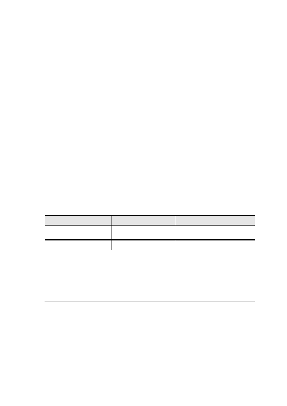
(1) Classification for protection in a normal service situation.
(2) Classification for protection in a abnormal service situation. These accessories are fire sized for a thermal flux
of 10kW/m2. No combustible material should be within 6.5m of the unit.
(3) The momentary overpressure limited to 10% of the service pressure does not apply to this abnormal service
situation.
The set pressure may be above the operating pressure. In this case, the failure to exceed the operating
pressure under normal operating conditions is ensured either by the design temperature or by the high
pressure switch.
(4) The classification of these valves must be done by the integrators who carry out the entire hydraulic
installation.
SI — International System of Units
SIOB — Starfire 2 Input Output Board (for Purge system control)
VFD — Variable Frequency Drive
The PIC5+ software version number of your 19DV unit will be located on the HMI module.
Information on the unit control is not included in this manual. Refer to separate controls manual.
2.3 Chiller technical documentation (wiring diagram, dimensional
drawings, PID)
All figures, chiller view, and schematics of the IOM documents are not contractual not-certified drawings. Please
refer to the certified drawings and electrical diagrams supplied with the unit or available on request, when
designing and installation.
Weight and dimensions are not-certified and only indicative data. Please refer to certified drawings of the selected
chiller.
2.4 CE marking
19DV chillers with CE marking have been designed and manufactured according to the following European
directives:
- Pressure Equipment Directive 2014/68 / EU, by application of harmonized standard 378-2 Refrigeration
and heat pump systems Safety and environmental requirements
- Machinery Directive 2006/42 / EC, by application of Harmonized Standard 60204-1: Safety of machinery Electrical equipment of machines - Part 1: General rules
- Electromagnetic compatibility (EMC) 2014/30 / EU by application of harmonized standard 61800-3 for
variable speed drives.
The electromagnetic emission and immunity levels comply with the requirements for an industrial environment and
are not designed for operation in a residential environment.
This equipment uses and can emit radio energy. In the event of installation or use not in accordance with the
instruction manual, interference with radio communications may occur.
2.4.1 CLASSIFICATION
In accordance with the requirements of the Pressure Equipment Directive and the national regulations, the safety
accessories of the unit are classified as follows:
The unit is equipped with a safety loop, also called measurement, control and regulation devices playing a role in
safety (SRMCR for protection against overpressure that could be created by the compressor).
Made of :
- 2 active pressure switches (HPS) at compressor discharge
- Safety relay inside the control cabinet
- Power contactor inside the VFD
- VFD
This SRMCR is designed in accordance with EN ISO 13849-1: 2016 according to the following characteristics:
- PL d
- Category 3.
- Mission duration 20 years.
10
Page 11

2.5 - Chiller familiarization 19DV
2.5.1 - Chiller information plate
The chiller information plate is located in front of the electrical control box.
2.5.2. System components
The main components include the cooler and condenser heat exchangers in separate vessels, motorcompressor, refrigerant, lubrication package, control panels, PIC5+ Touch Screen HMI, economizer, VFD, and
purge system.
2.5.2.1. Cooler
This vessel is located underneath the compressor. The cooler is maintained at lower temperature/pressure so
evaporating refrigerant can remove heat from water flowing through its internal tubes. Water is flowing through the
tube internals to provide comfort or process cooling.
2.5.2.2. Condenser
The condenser operates at a higher temperature/pressure than the cooler and has water flowing through its
internal tubes in order to remove heat from the refrigerant. It contains a metering device that regulates the flow of
refrigerant into the economizer.
2.5.2.3. Economizer
This chamber reduces the refrigerant pressure to an intermediate level between the evaporator and condenser
vessels. In the economizer, vapor is separated from the liquid, the separated vapor flows to the second stage of
the compressor, and the liquid flows into the cooler.
The energy removed from the vaporized refrigerant in the economizer allows the liquid refrigerant in the cooler to
absorb more heat when it evaporates and benefits the overall cooling efficiency cycle. It contains a float assembly
that regulates the flow of refrigerant into the evaporator.
2.5.2.4. Motor-compressor
This component maintains system temperature and pressure differences and moves the heat-carrying refrigerant
from the cooler to the condenser. The 19DV utilizes a two-stage back to back direct drive configuration.
2.5.2.5. Purge unit
A small independent condensing unit with compressor, separator, regenerative carbon filters heater and vacuum
pump. The purge extracts gas from condenser (or from compressor if unit is not in operation) and purifies it by
removing non-condensable gases and any water vapor that may be present.
2.5.2.6. Variable Frequency Drive (VFD)
A variable-frequency drive allows start-up and compressor motor power supply interruption. It also allows
adjustment of the compressor speed based on the required capacity. It is either factory-installed in the unit in a
cabinet that also includes the protection and power transmission elements, or not unit-mounted.
2.5.2.7. Refrigerant lubrication system
This system provides lubrication to the compressor bearing by means of a refrigerant pump.
2.5.2.8. Chiller control cabinet
This control panel includes the input and output boards (IOB), control transformer, relays, contactors, and circuit
breakers. It provides the power distribution and protection to the electrical components installed on chiller and has
the following functions:
• Communication with PIC5+ touch screen
• Communication with purge panel
• Communication with VFD
• Sensor input and outputs
• Actuators control
• Refrigerant pump control
2.5.2.9. Purge control panel
The purge panel includes the input and output board, control transformer, relays, and fuse. It provides the power
distribution and protection to the electrical components which installed in the purge system and has the following
functions:
• Communication with PIC5+ touch screen
• Sensor input and outputs
• Solenoid valve control
11
Page 12

• Control of purge compressor, vacuum pump, heater, and fan.
Model number
(example)
19
DV
G44
G44 4 4 4 A H 9
(1)
(2)
(3)
(4)
(5)
(6)
(7)
(8)
(9)
(10)
Service number
(example)
19DV
G44
G44
444
001 E -
(1)
(2)
(3)
(4)
(5)
(6)
2.5.2.10. PIC 5+ Touch screen HMI
This panel is the user interface for controlling the chiller and has the following functions:
• Chiller operation
• Chiller diagnostic
• Chiller status display
• Chiller parameter configuration
• Provide open protocol interface to outside BMS system
2.5.3 Product identification
1 : High Efficiency Semi-Hermetic Centrifugal Chiller
2 : D : low pressure V : Variable Speed Drive
3 : Evaporator frame size (Length, Pass arrangement, tube count)
4 : Condenser frame size (Length, Pass arrangement, tube count)
5 : Compressor frame size / 4 : 1758 – 2813 kW
6 : Compressor shroud code (3-4-5-6)
7 : Compressor Impeller Diameter Code (2 – 4)
8 : VFD code * (A : high tier LF2 Rockwell / 5 : low tier VFD / 0 : Freestanding)
9 : Motor code * (B/D/F/H)
10 : Motor voltage code 3: 380/3/60 4 : 416/3/60 5 : 460/3/60 9 : 400/3/50
1 : Chiller designation
2 : Evaporator designation
3 : Condenser designation
4 : Compressor designation
5 : Unit manufacturing incrementing number
6 : E : Unit manufactured at MTL factory
Figure 1 – Chiller model identification
12
Page 13
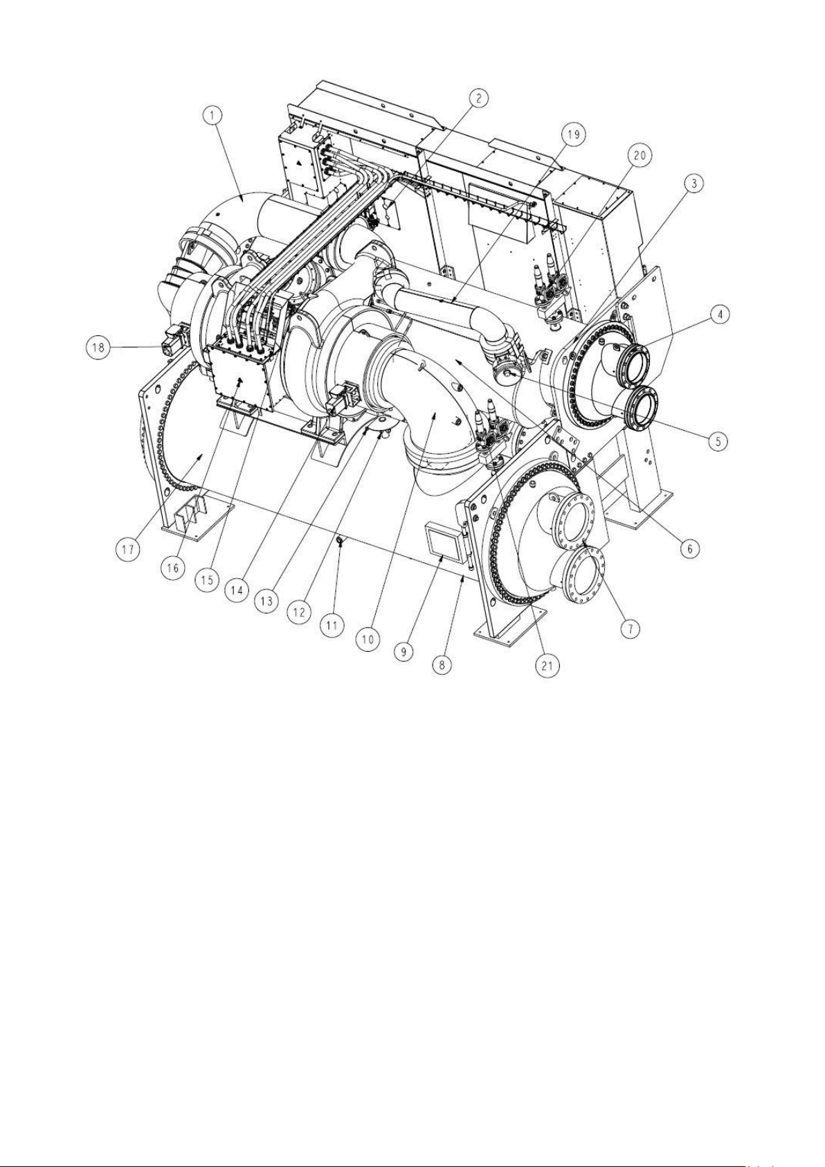
1. Interconnecting Compressor Piping (ICP) from 1st stage to 2nd stage
2. VFD cooling piping
3. Condenser
4. Condenser waterbox nozzles
5. Economizer isolation valve (option)
6. Economizer
7. Evaporator waterbox nozzles
8. Evaporator
9. PIC5+ HMI touchscreen panel
10. Suction elbow
11. Evaporator sightglass
12. Evaporator charging valve
13. Evaporator pressure transducer
14. 1st stage Inlet Guide Vane (IGV) actuator
15. Compressor
16. Motor terminal box
17. Power cables from VFD to compressor motor
18. 2nd stage Inlet Guide Vane (IGV) actuator
19. Economizer pipe
20. Condenser relief valve assy
21. Evaporator relief valve assy
13
Page 14
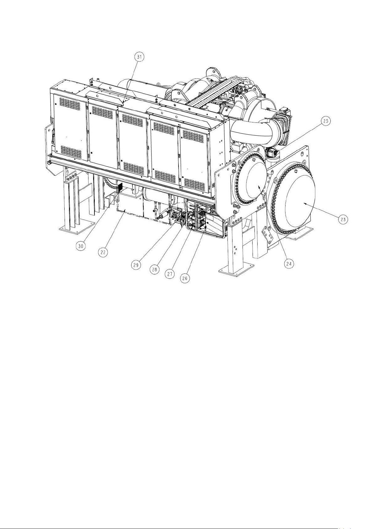
22. Control cabinet
23. Evaporator return end waterbox
24. Condenser return end waterbox
25. Envelop stability control valve (ECV) (option)
26. Purge system assy
27. Lubrication assy
28. VFD
29. Chiller serial plate label
30. Pressure switches assy
Figure 2 – Typical 19DV chiller components (Chiller shown with LF2 2CC VFD model)
14
Page 15
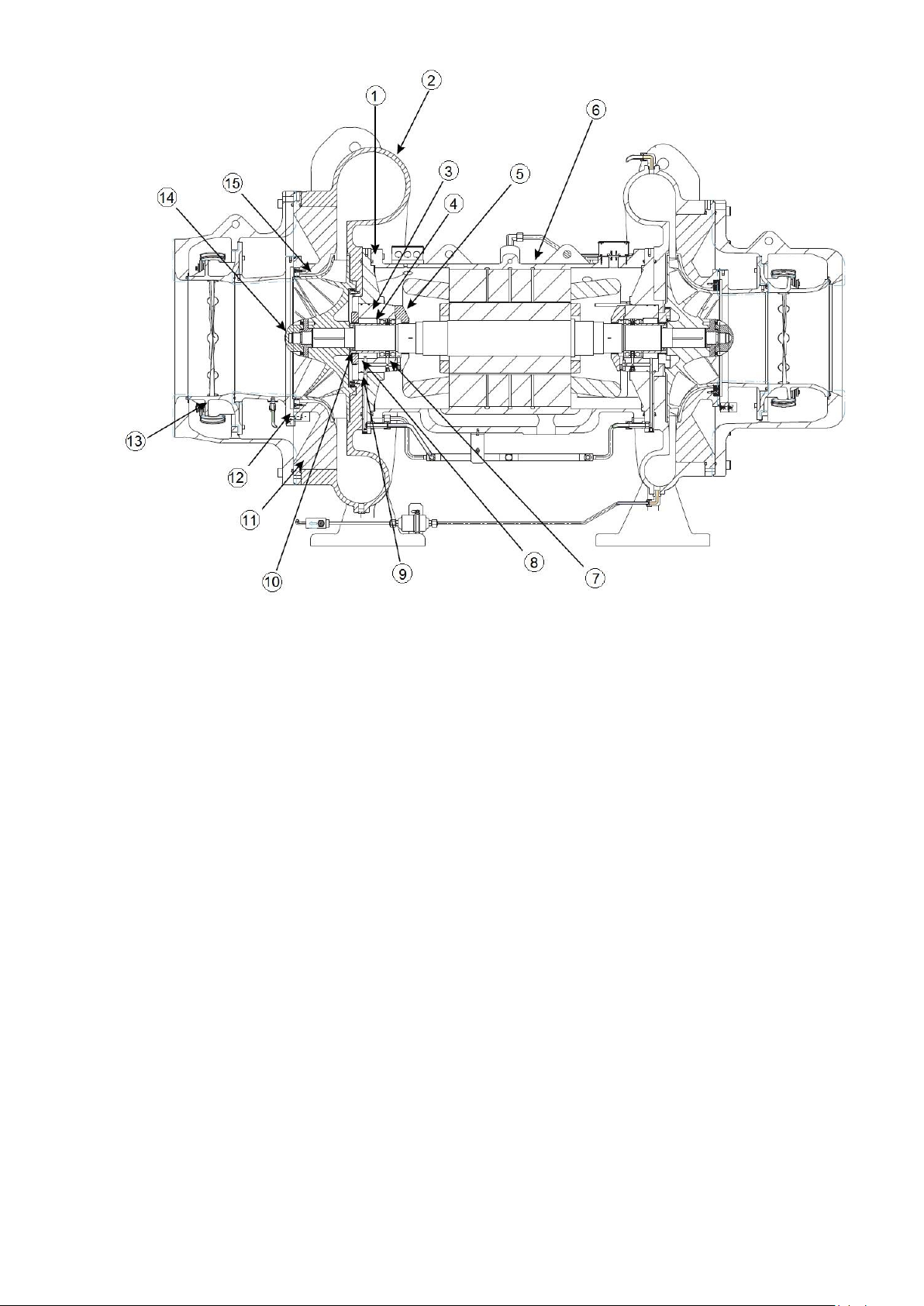
1. Bearing support housing
2. Volute
3. Bearing housing
4. Spacer / sizer
5. Motor shaft laby
6. Motor housing
7. Roller element bearing assembly
8. Impeller labyrinth
9. Bearing flange
10. Impeller shim
11. Shroud
12. Eye laby
13. IGV
14. Nose piece
15. Impeller
Figure 3 – Typical 02DV compressor internal view
2.5.4 - Refrigeration cycle
The compressor continuously draws refrigerant vapor from the evaporator at a rate set by the amount of first stage
guide vane opening and motor speed. As the compressor suction reduces the pressure in the evaporator, the
remaining refrigerant boils at a fairly low temperature (typically 3 to 6°C). The energy required for boiling is
obtained from the water flowing through the evaporator tubes. With heat energy removed, the water becomes cold
enough to use in an air-conditioning circuit or process liquid cooling.
After taking heat from the water, the refrigerant vapor is compressed by a back-to-back compression connected by
means of interstage piping. Compression adds heat energy and the refrigerant is quite warm (typically 37 to 40°C)
when it is discharged from the compressor into the condenser. Relatively cool (typically18 to 32°C) water flowing
into the condenser tubes removes heat from the refrigerant, and the vapor condenses to liquid. The liquid drains
into a high side float valve chamber between the condenser and the economizer. The refrigerant is then metered
into the economizer.
15
Page 16
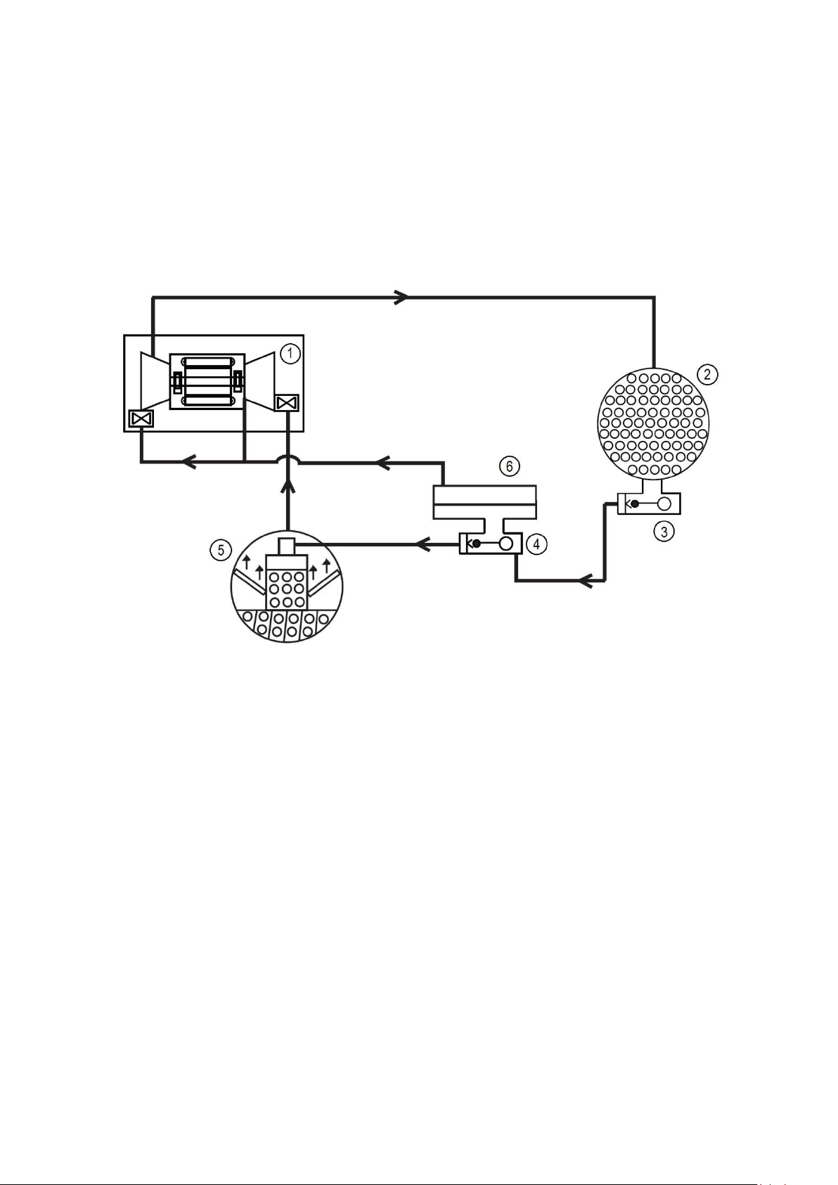
In the economizer, due to lower pressure, as liquid enters the high side chamber, some liquid will flash into a
vapor and cool the remaining liquid. The separated vapor flows to the second stage of the compressor for greater
cycle efficiency. The second stage guide vane on the compressor acts as a pressure regulating device to stabilize
operating conditions. At part load the second stage guide vane will back up gas flow and thereby raises the
economizer pressure to allow appropriate refrigerant flow from economizer to the compressor.
The cooled liquid left in the economizer flows through a low side float valve and then into the evaporator. The float
valve forms a liquid seal to keep vapor from entering the evaporator. The refrigerant is now at a temperature and
pressure at which the cycle began. Fig. 4 summarizes the refrigeration cycle.
The 19DV unit utilizes R-1233zd(E) refrigerant. At atmospheric pressure its boiling point is 18.6°C. The result is
that at normal operating conditions the evaporator typically will be in a vacuum condition and the condenser will
operate at a pressure above atmospheric pressure. Unit near room temperature will be close to atmospheric
pressure.
1.Compressor
2.Condenser
3.High side float chamber
4.Low side float chamber
5.Cooler
6.Economizer
Figure 4 – Refrigeration cycle – 19DV Two Stage Compressor
CAUTION: To avoid adverse effects on chiller operation, considerations must be made to condenser water
temperature control. For steady state operation, the minimum operating refrigerant pressure differential between
cooler and condenser is approximately 7 psid (48 kPa) with a maximum evaporator refrigerant temperature of 18°C.
Consult Chiller Builder for required steady state operational limits and low lift options. Inverted start conditions are
acceptable for short durations of time, but for periods exceeding 5 minutes, a special control solution strategy should
be used to allow the chiller to establish a minimum refrigerant pressure differential (and thereby adequate
equipment cooling).
2.5.5 Refrigerant lubrication cycle
2.5.5.1 Summary
The 19DV Series chiller uses refrigerant to lubricate the bearings. The lubrication control is automatically
controlled by the chiller controls. In normal RUN mode refrigerant is pumped by means of a refrigerant pump from
the high side condenser float chamber to the bearings. Prior to start-up liquid level in the high side condenser float
chamber is maintained by pumping refrigerant liquid from the evaporator to the high side float chamber until level
sensor is satisfied.
If liquid high side float level is not satisfied the pump will move refrigerant from the evaporator to the condenser.
Figures 5 and 6 identify the refrigerant lubrication assembly.
16
Page 17
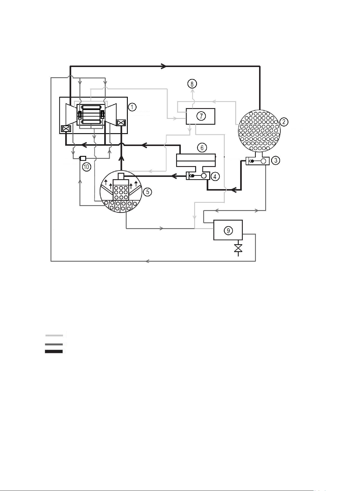
Supply refrigerant is pulled through a filter drier by the refrigerant pump and is pumped to the bearings through
two protective filters and then returned to the evaporator.
There are two pressure sensors located across the refrigerant pump. During RUN mode a minimum of 82.7 kPa is
required for the refrigerant pump delta difference. An alert will trigger if this value is less than 89.6 kPa while the
machine is in normal operating mode. Consult the Controls Operation and Troubleshooting Manual for details.
1.Compressor
2.Condenser
3.High side float chamber
4.Low side float chamber
5.Cooler
6.Economizer
7. Purge system
8. Vent line
9. Refrigerant lubrication system
10. Eductor
: Purge
: Lube system
: Main refrigerant system
Figure 5 – Refrigerant lubrication Cycle
2.5.5.2 Bearings
The 19DV motor-compressor assembly include two sets of purely refrigerant lubricated bearings. The motor shaft
is supported by a combination set of journal bearing and roller element bearings on each end of compressor.
The refrigerant lubrication pressure difference is defined as the bearing input pressure minus the bearing output
pressure plus the Refrigerant Delta P Offset.
17
Page 18
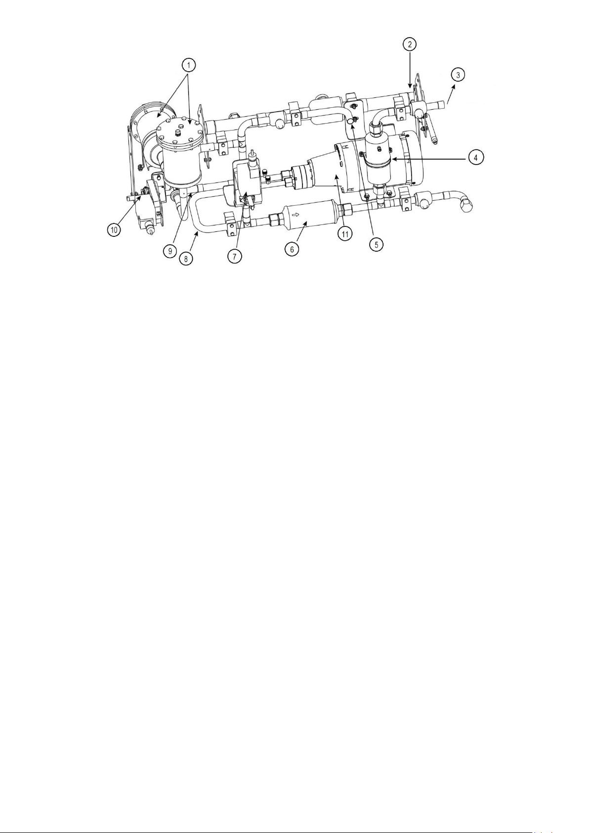
1. Strainer
2. From evaporator
3. To compressor motor bearings
4. Filter
5. From high side float chamber
6. Filter
7. Actuator, condenser valve
8. Pump discharge
9. Pump suction
10. Actuator and 3 way valve, cooler valve
11. Pump
Figure 6 – Refrigerant lubrication Assembly
2.5.5.3 Motor cooling system
The motor is cooled by liquid refrigerant taken from the bottom of the high side condenser float chamber.
Refrigerant flow is maintained by the pressure differential that exists due to compressor operation. After the
refrigerant flows past an isolation valve, an in-line filter drier, and a sight glass/moisture indicator, it is directed
over the motor by spray nozzles. The refrigerant collects in the bottom of the motor casing and is then drained
back into the cooler through the motor refrigerant drain line. The motor is protected by temperature thermistors
embedded in the stator windings. An increase in motor winding temperature past the motor override set point
overrides the temperature capacity control to hold, and if the motor temperature exceeds 5.5°C above this set
point, the controls close the inlet guide vanes. If the temperature rises above 50°C, the compressor shuts down.
See Fig. 7.
18
Page 19
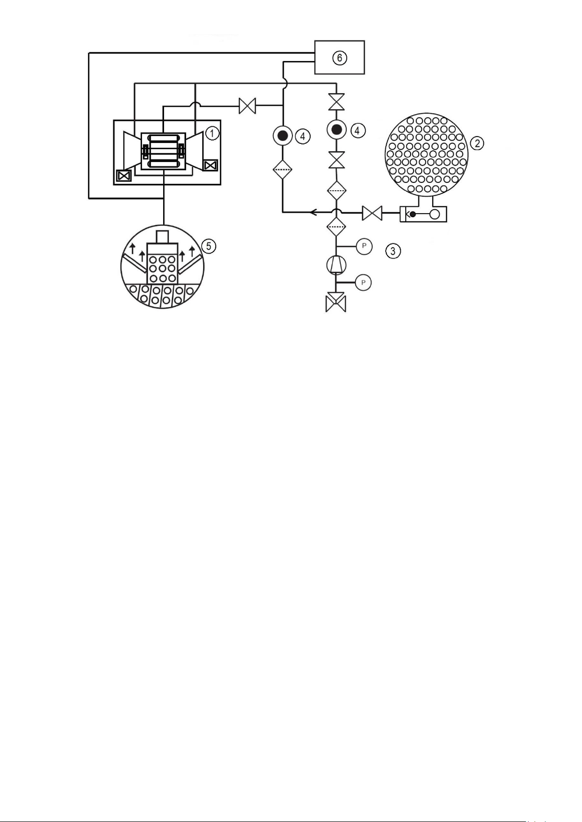
1.Compressor
2.Condenser
3.Motor cooling system
4.Moisture indicator
5.Cooler
Figure 7 – Motor/VFD cooling system
2.5.5.4 VFD cooling
The VFD enclosure is sealed from the atmosphere to protect electronics from outside contaminants. Refrigerant is
routed through a coil in the VFD enclosure to regulate enclosure temperature while still maintaining a temperature
high enough to prevent condensation.
VFD cooling line is branched off the motor cooling supply. The refrigerant is then drained back into the cooler
through the motor/VFD drain line. The power module of the variable-frequency drive is equipped with a heat
exchanger to provide cooling, using the refrigerant in the machine. If equipped with a unit-mounted VFD, the
refrigerant line that feeds the motor cooling also feeds the heat exchanger on the unit-mounted VFD.
2.5.5.5 VFD
All 19DV units are equipped with a VFD to operate the centrifugal hermetic compressor motor. The VFD and
control panel are the main field wiring interfaces for the installing contractor. The VFD and control panel are most
of time mounted on the chiller. See Manufacturer VFD specific information and VFD schematics.
This VFD is used with low voltage motors between 380 and 460 vac. It reduces the starting current inrush by
controlling the voltage and frequency to the compressor motor. Operational parameters and fault codes are
displayed relative to the drive. Refer to specific drive literature along with troubleshooting sections. The display is
also the interface for entering specific chiller operational parameters. These parameters have been
preprogrammed at the factory. VFD is designed to operate in an ambient range of up 40°C.
The compressor power variable-frequency drive cabinet includes the following functional components (identified in
accordance with the references on the wiring diagram):
19
Page 20
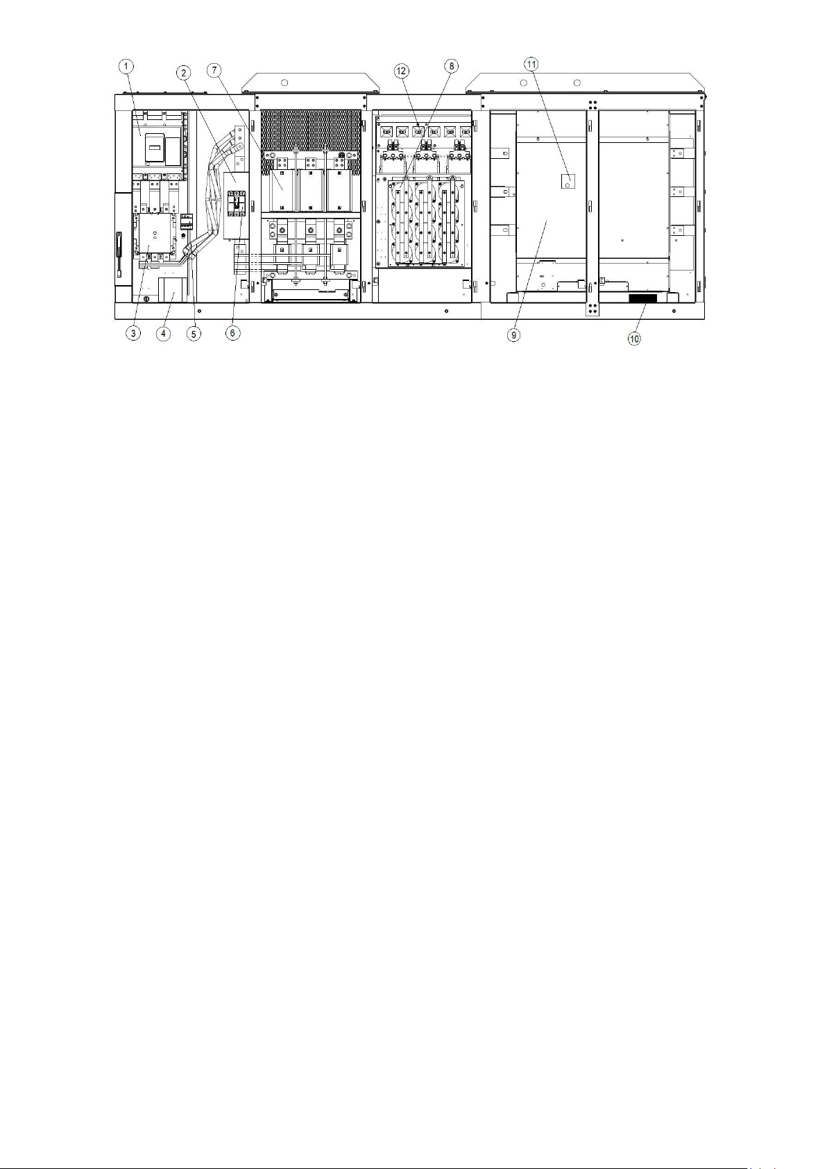
Fig 8 – VFD cabinet view (example of LF2 4AA)
1. Circuit breaker/main disconnect switch (QF101) for the following functions:
- Short-circuit protection of the main circuit
- Single connection point of the installation power cables
- Isolation and shut-down of the machine, using the handle accessible on the outside of the control box
- Emergency stop, initiated by the PIC control
2. Filter CEM RFI (ZGS) to limit high-frequency conductor interferences (>150 kHz).
3. Power safety contactor (K101)
4. Power transformer (T1) and fuse (FU10) for the internal control circuit of the variable-frequency drive.
5. Surge limiter (F).
6. Power supply circuit protection disconnect switch for the PIC control box (QF).
7. Load resistor shunt capacitors (K1-). They short-circuit the load resistors when the capacitors are loaded.
8. Capacitor resistors (R1-3C) and coils for inlet filtering of the main circuit
9. Power module and associated control interface board (GS) for the following functions:
- Compressor start-up and shutdown by voltage/frequency ramping to permit limiting of the couple and inrush current at start-up
- Control of the voltage/frequency applied to the compressor
- All electrical compressor protection devices
- All devices to protect against internal faults of the variable-frequency drive as well as pressure safety switch cut-out and re-starting the oil pump
- Report of variable-frequency drive status parameters and internal faults to the PIC control.
10- Terminal connections (XP), I/O with chiller (Gatekill chain from pressure switches terminals, run feedback, com… )
11. Communication gateway board. Provides the communication interface between the variable-frequency drive and the PIC control.
12. Load resistors of the main power circuit (R4-6C) and protection fuses of the load circuit (FU**). To limit the inrush current while power is
supplied to the variable-frequency drive.
20
Page 21
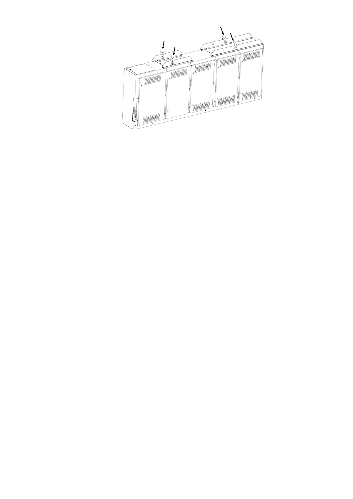
Fig 9 – VFD cabinet lifting lugs
2.5.5.6 Purge system
The purge system is located under the condenser. See Fig. 10. It has two gas inlets coming from condenser and
compressor. When chiller is running, the condenser line is active/open and non-condensable gas will pulled out
from condenser and when chiller is idle the compressor line is active and non-condensable are pulled out from
compressor volute. This is implemented due to non-condensable gas density being less than refrigerant and
therefore it will accumulate at the highest point when chiller is not running.
In the purge tank the purge gas is cooled by a separate integral R-134a cooling system. The cooling system
consists of an compressor, an air cooled condenser coil, an expansion valve, and a cooling coil in purge tank.
Cooling the purge gas results in condensation of R-1233zd(E) vapor as it touches the coil resulting in a vacuum
which the result that more refrigerant is pushed to the coil. As the purge tank fills up with refrigerant it will be
drained through the purge drain to the refrigerant pump assembly. See Fig. 11.
Non-condensable that comes into contact with the cold coil in the purge tank will not condense and will
accumulate at the top of the purge tank. When the controls sense that there is sufficient non-condensable gas in
the purge tank, the control will open the pumpout valve, activate the purge evacuation pump, and force the gas
through the active carbon filters. To capture any remaining refrigerant the gas is routed through two active carbon
filters that will absorb any remaining refrigerant. As the carbon filters becomes saturated the system will
regenerate the filters by applying heat to the filters while under vacuum and then disperse the regenerated
refrigerant back to the cooler while releasing the non-condensable to atmosphere.
The 19DV purge control is automatic. Purge control should be active when purge inlet temperature (evaporator
refrigerant liquid temp when chiller compressor OFF or condenser saturated temperature when chiller compressor
ON) is greater than purge active temperature set point default 18.3°C. If chiller compressor is running, condenser
solenoid valve should be opened to purge refrigerant from condenser.
If chiller compressor is not running, open the compressor solenoid valve to purge refrigerant from compressor. If
Purge Comp Suction Temp is less than purge compressor off temp (default to -15.5°C) and the refrigerant level
flag is ON, close compressor solenoid valve, condenser solenoid valve, and open pump out solenoid valve. Purge
vent valve and purge vacuum pump shall be kept ON for about 10s. After 10s discharge, pump out solenoid valve,
purge vent valve, and purge vacuum pump shall be kept OFF. Condenser solenoid valve shall be opened if chiller
compressor is running or compressor solenoid valve shall be opened if chiller compressor is not running.
After 10s discharge, it will start 20s delay. Then, check purge compressor suction temperature again; if it is less
than -14°C, it will continue cycle as before.
If refrigerant level in the purge tank is high (both PGLE_HI and PGLE_LO are ON), or purge compressor suction
temperature is less than -11°C and PGLE_LO is ON, then drainage solenoid valve should be opened to drain
refrigerant from purge tank to evaporator (open SV04, SV01, SV02 when chiller is off, open SV04, SV01 when
chiller is on). After PGLE_LO is OFF, keep drain process for another 1s, then set the refrigerant level flag to ON. If
purge level in the purge tank is low (both PGLE_HI and PGLE_LO are OFF), drainage solenoid valve should be
closed.
If pump out solenoid valve is accumulated ON for 100 minutes, purge system should do regeneration process for
reg_tim minutes (default = 120 minutes - 19DV Configuration Menu), regardless whether purge is active. When
regeneration process active, the Purge Regeneration Valve and Purge Heater should be on for reg_tim minutes,
purge vacuum pump should be on for 3 minutes and then 10 minutes off, alternating during reg_tim minutes. Upon
regeneration completion, purge system will wait for another 4 hours to let carbon filter cool down before it will
operate normally.
21
Page 22
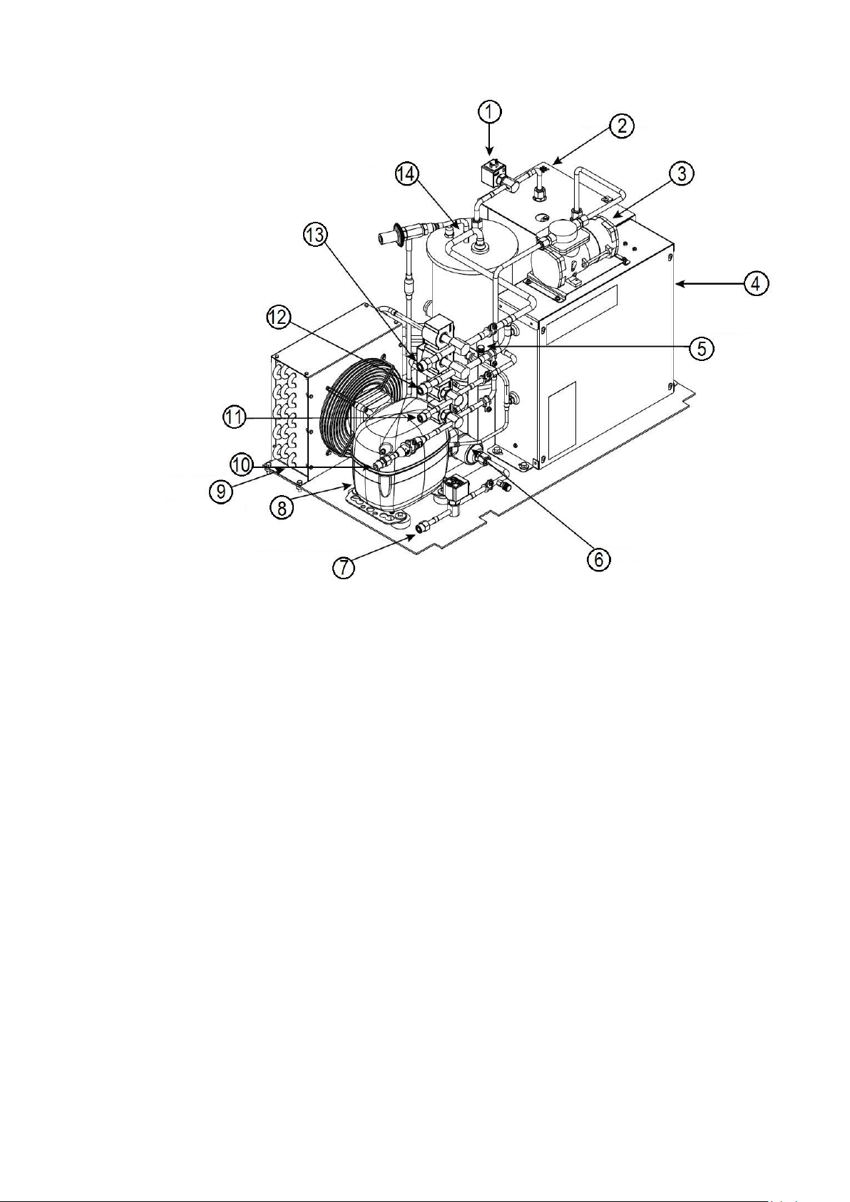
1. Purge pumpout (SV01)
2. Extra filters with strap heaters (not shown)
3. Vacuum pump
4. Control panel
5. Compressor suction
6. Strainer
7. Purge drain (SV04) – connected to refrigerant pump inlet piping
8. Compressor
9. Condenser assembly
10. Venting (SV06), non-condensable exhaust
11. Connected to motor drain (SV05)
12. Connected to chiller condenser (SV01)
13. Connected to compressor volute (SV02)
14. Purge tank
Fig 10 – purge system
22
Page 23
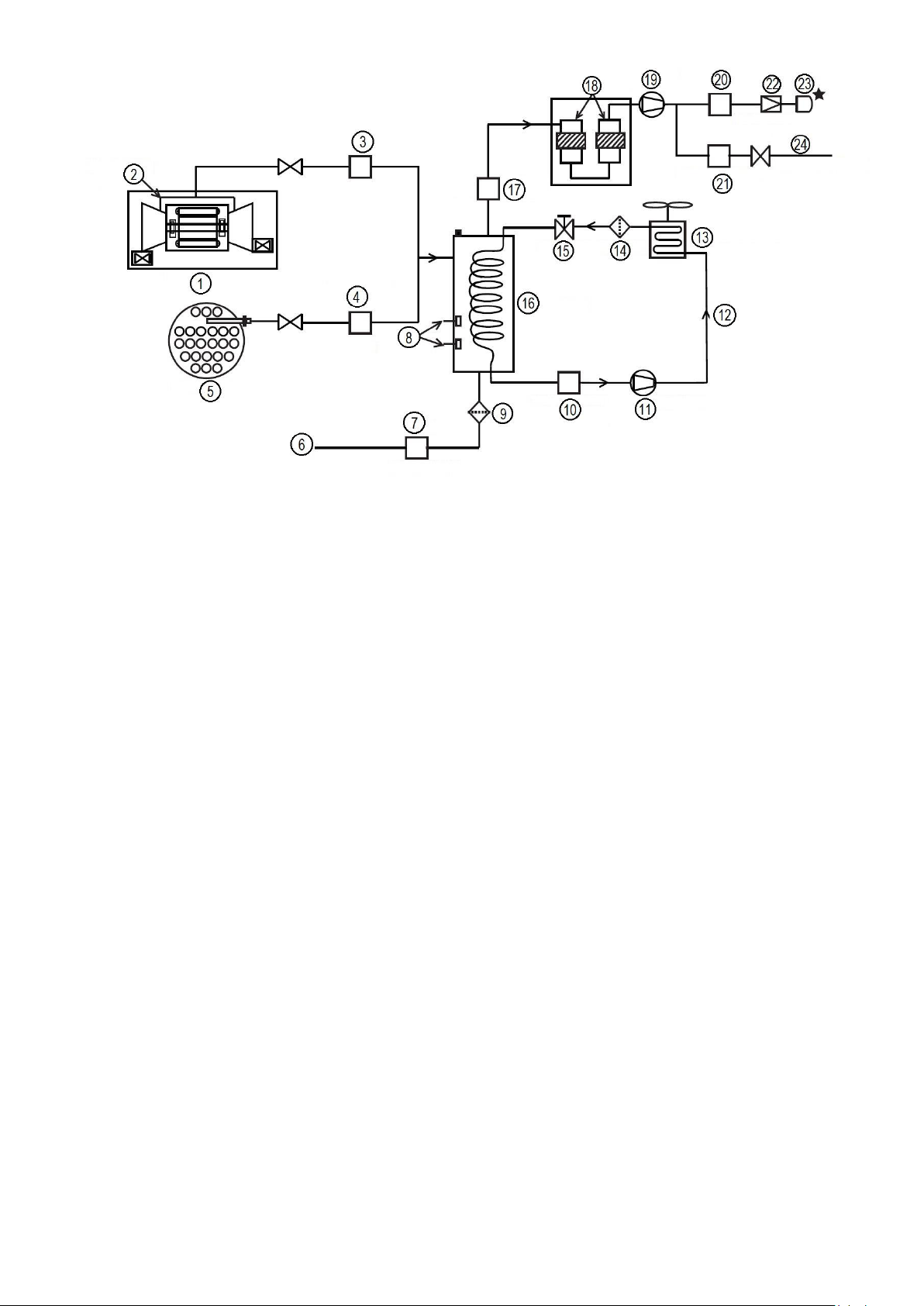
1. Compressor
2. Check valve (hidden)
3. Compressor valve (SV02)
4. Condenser valve (SV01)
5. Condenser
6. Purge drain (to lube assy)
7. Drain valve (SV04)
8. Level switches
9. Strainer
10. Suction temperature
11. Purge compressor
12. R134a circuit
13. Purge condenser assy
14. Strainer
15. Throttle service
16. Sight glass
17. Pumpout valve (SV03)
18. Carbon filters
19. Vacuum pump
20. Vent valve (SV06)
21. Regeneration valve (SV05)
22. Check valve
23. Vent line (field connection / purge vent 3/8 NPT)
24. Regenerated refrigerant (to motor drain)
Fig 11 – purge system diagram
23
Page 24
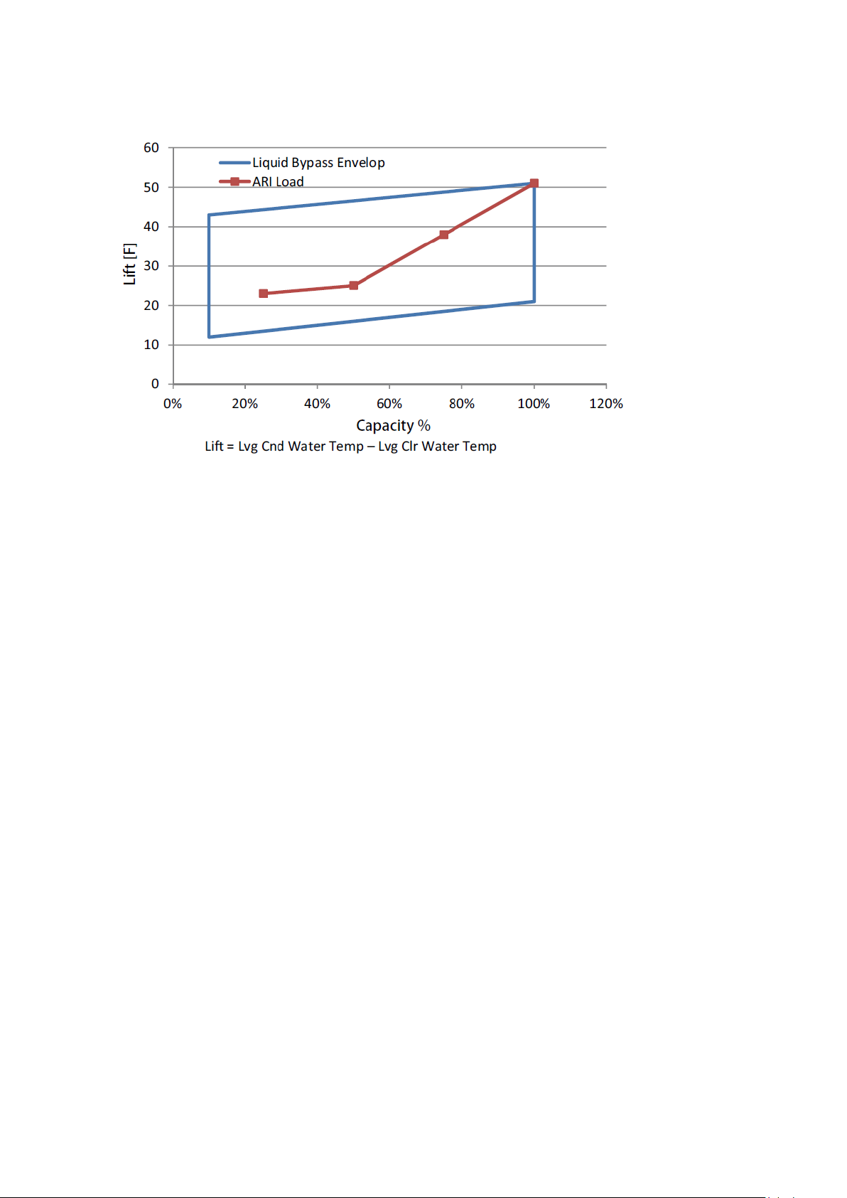
2.5.5.7 Liquid bypass
The liquid bypass (LBP) system will be an option for customer when the chiller operation envelope has lower
profile like below:
Fig 12 – liquid bypass envelop
At very low Entering Condenser Water Temp, the pressure difference between condenser and evaporator is
reduced. At bigger system flow rate, the piping resistance may get higher than system pressure difference. In this
case, the liquid may stack in the condenser or the economizer, and cause evaporator lack of refrigerant.
Therefore, the chiller will easily get tripped out due to low evaporating temperature alarm.
The LBP system is designed to avoid above operation failure. It includes an Economizer Bypass Valve installed
between condenser float chamber and evaporator inlet piping, an Economizer Isolation Valve installed on the
vapor piping between economizer and compressor interstage.
When the LBP is activated, the chiller will operate as a single stage system. The condenser float valve will still
control the system flow rate according to the chamber liquid level.
When system lift decrease, and evaporating saturated temperature goes to below evaporator freezing point
(default 0.56°C) for a period of time, or when the Leaving Condenser Water Temperature minus Leaving Evap
Water Temperature is less than 11.8°C and Cooler LTD is larger than 2.78°C for a period of time, the valve
installed on bypass piping will be actuated to fully open, and the valve installed on the economizer vapor piping
needs to be closed completely.
When the system lift increase, the bypassed line will pass more refrigerant than the system requires. So the
evaporator will have too much refrigerant, and its liquid level will increase to cause liquid carryover to the
compressor. The system discharge temperature difference (DTD) will drop down.
When the DTD is less than the required, close the bypass valve and open the economizer vapor line valve, then
the system will switch back to a two stage economized cycle.
24
Page 25

2.6 – CONTROLS
2.6.1 Definitions
ANALOG SIGNAL — An analog signal varies in proportion to the monitored source. It quantifies values between
operating limits. (Example: A temperature sensor is an analog device because its resistance changes in proportion
to the temperature, generating many values.)
DISCRETE SIGNAL — A discrete signal is a 2-position representation of the value of a monitored source.
(Example: A switch produces a discrete signal indicating whether a value is above or below a set point or
boundary by generating an on/off, high/low, or open/closed signal.)
2.6.2 General
The 19DV centrifugal liquid chiller contains a microprocessor-based control center that monitors and controls all
operations of the chiller. The microprocessor control system matches the cooling capacity of the chiller to the
cooling load while providing state-of-the-art chiller protection.
The system controls cooling load within the set point plus the deadband by sensing the leaving chilled water or
brine temperature and regulating the inlet guide vanes and compressor speed. The guide vane is a variable flow
pre-whirl assembly that controls the refrigeration effect in the cooler by regulating the amount of refrigerant vapor
flow into the compressor. An increase in guide vane opening increases capacity. A decrease in guide vane
opening decreases capacity. The microprocessor-based control center
protects the chiller by monitoring the digital and analog inputs and executing capacity overrides or safety
shutdowns, if required. The variable frequency drive (VFD) allows compressor start-up and capacity control by
modulating the motor frequency based on the operation condition.
2.6.3 PIC 5+ system components
The chiller control system is called the PIC5+ (Product Integrated Control 5).
As with previous PIC versions, the PIC5+ system controls the operation of the chiller by monitoring all operating
conditions. The PIC5+ control system can diagnose a problem and let the operator know what the problem is and
what to check. It positions the guide vanes and VFD speed to maintain leaving chilled water temperature. It
controls the refrigerant pump providing compressor bearing lubrication and can interface with auxiliary equipment
such as pumps and cooling tower fans to turn them on when required.
It continually checks all safeties to prevent any unsafe operating condition. It regulates the envelope control
valve for stabilized aerodynamic operation, if installed. The PIC5+ controls offer an operator trending function to
help the operator monitor the chiller status more easily and for critical compressor motor protection. The PIC5+
system provides open protocols to support the competitive BMS system and can be integrated into Carrier’s
Lifecycle System Management for remote monitoring and data management.
25
Page 26
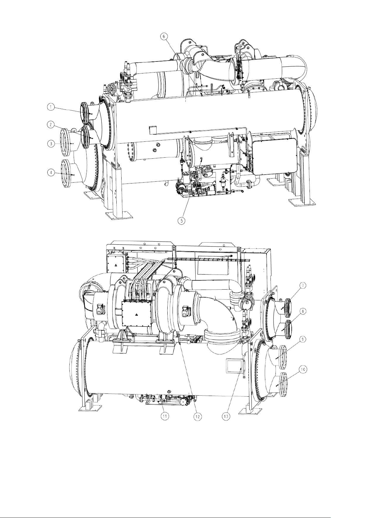
(VFD not shown)
Fig 13 – Sensors, actuators location
26
Page 27
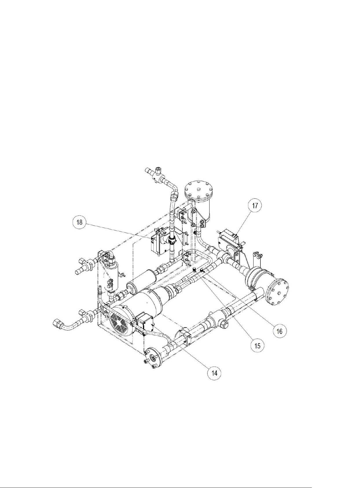
1. Condenser water outlet temperature sensor (RT8)
2. Condenser water inlet temperature sensor (RT7)
3. Evaporator water outlet pressure transducer (BP12)
4. Evaporator water inlet pressure transducer (BP13)
5. High side level switch (HF_LS)
6. Condenser refrigerant pressure transducer (BP1)
7. Condenser water outlet pressure transducer (BP14)
8. Condenser water inlet pressure transducer (BP15)
9. Evaporator water outlet temperature sensor (RT2)
10. Evaporator water inlet temperature sensor (RT1)
11. Evaporator refrigerant liquid temperature sensor (RT15)
12. Evaporator refrigerant pressure transducer (BP3)
13. PIC5+ HMI touchscreen panel
14. Refrigerant pump motor terminal
15. Refrigerant pump outlet pressure transducer (BP81)
16. Refrigerant pump inlet pressure transducer (BP80)
17. Evaporator control valve (ECV1)
18. Condenser control valve (CCV1)
Fig 13 – Sensors, actuators location (cont.)
27
Page 28
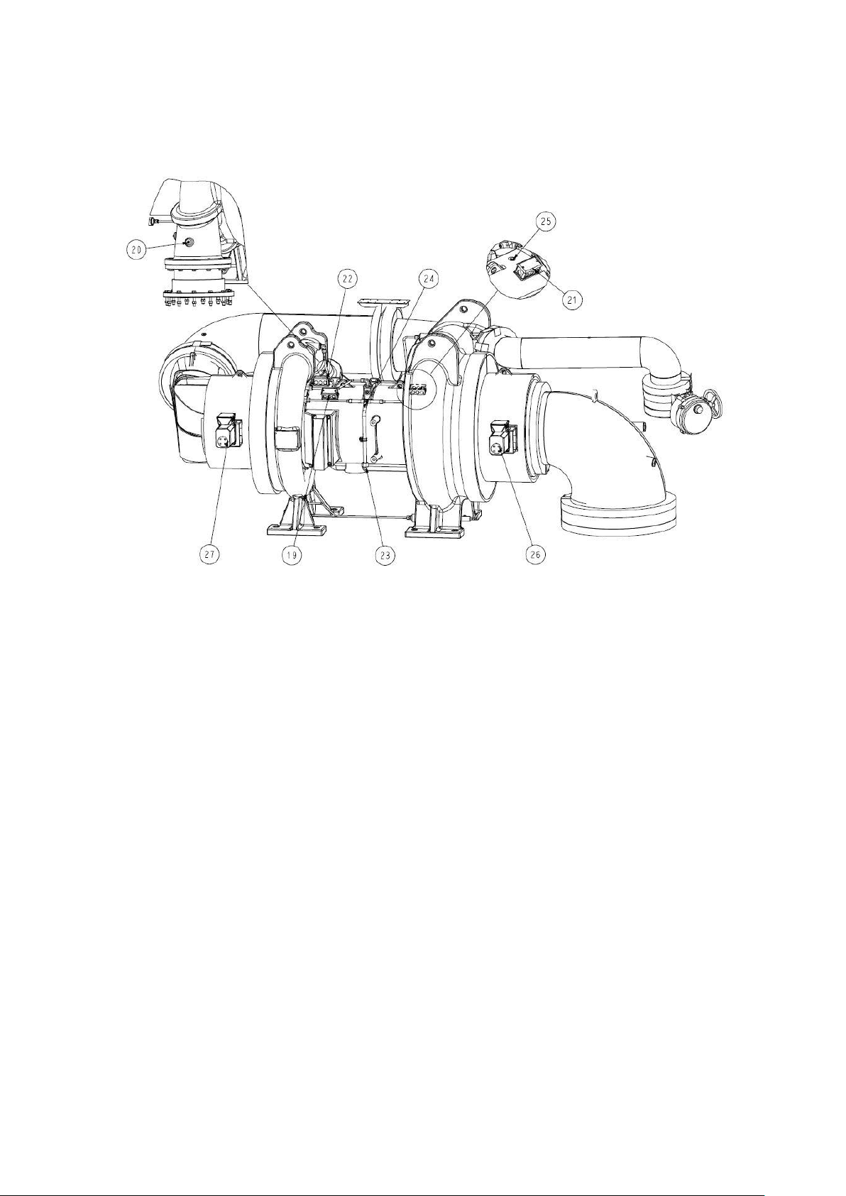
19. Motor winding temperature sensor (RT31C)
20. Compressor discharge temperature sensor (RT21)
21. 1st stage bearing temperature sensor (RT39C)
22. 2nd stage bearing temperature sensor (RT40C)
23. Bearing refrigerant supply temperature sensor (RT41)
24. Bearing inlet pressure transducer (BP70)
25. Bearing outlet pressure transducer (BP71)
26. 1st Inlet Guide Vane actuator (M67)
27. 2nd Inlet Guilde Vane actuator (M69)
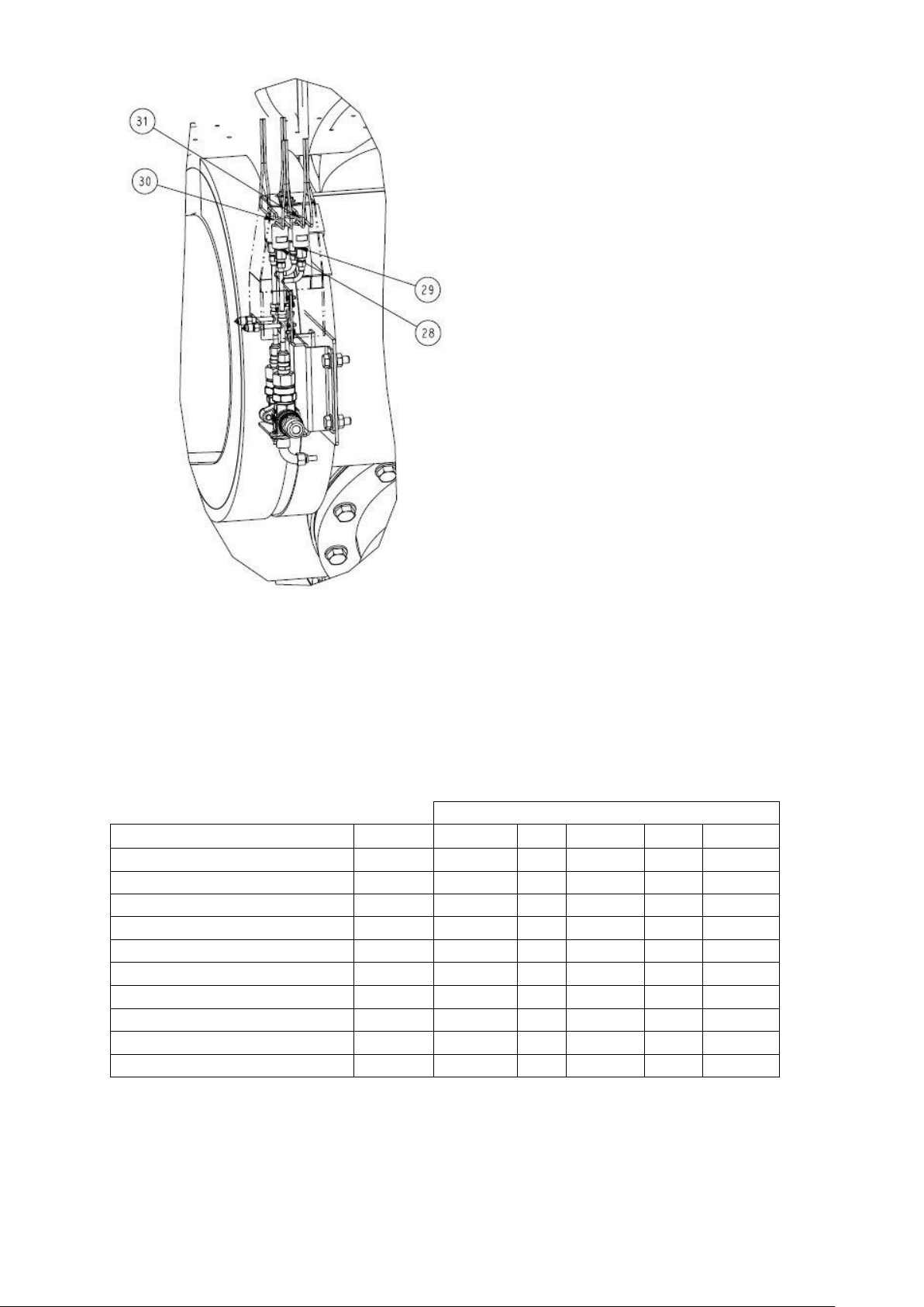
28. Pressure switch, safety device, (SP1FB)
29. Pressure switch, safety device, (SP1FA)
30. Pressure switch, safety device, spare (SP2FB)
31. Pressure switch, safety device, spare (SP2FA)
Fig 13 – Sensors, actuators location (cont.)
28
Page 29
Wiring information (see chiller wiring diagram)
Temperature sensor
Point Name
Designation
#IOB
# Channel
# Block
# Terminal
Entering chilled water temperature
ECW
RT1
IOB 1
AI1
J16
1-5
Leaving chilled water temperature
LCW
RT2
IOB 1
AI2
J16
2-6
Entering condenser water temperature
ECDW
RT7
IOB 1
AI3
J16
3-7
Leaving condenser water temperature
LCDW
RT8
IOB 1
AI4
J16
4-8
Evap. refrigerant liquid temperature
EVAP_T
RT15
IOB 1
AI5
J15
6-12
Compressor Discharge temperature
DGT
RT21
IOB 1
AI6
J15
5-11
Motor winding temperature 1
MTRW1
RT31C
IOB 2
AI1
J16
1-5
1st stage Bearing Temp
CBH1_T
RT39C
IOB 3
AI1
J16
1-5
2nd stage Bearing temp
CBH2_T
RT40C
IOB 3
AI2
J16
2-6
Bearing Ref Supply Temp
BRGI_T
RT41
IOB 3
AI3
J16
3-7
(VFD not shown)
Fig 13 – Sensors, actuators location (end)
2.6.4 Temperature sensors:
The system uses temperature sensors to measure and control the temperatures in the unit. There are three types
of temperature sensors, 5K thermistor (standard), 10K thermistor and RTD (three wires) based on the IOB
channel configurations.
The temperature sensor range is -40 ~ +118°C.
Table 1a – Temperature sensors
29
Page 30
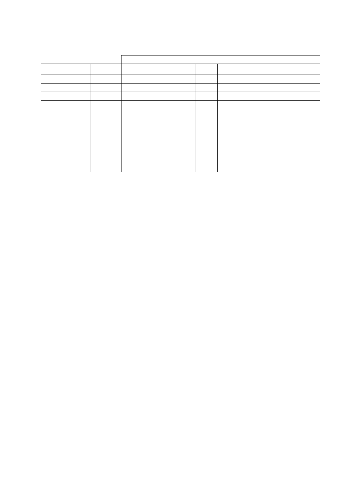
2.6.5 Pressure transducers
Wiring information (see chiller wiring diagram)
Pressure transducer type
Pressure sensor
Point Name
Designation
#IOB
#
Channel
# Block
#
Terminal
5VDC – low refr. Pressure range
Condenser pressure
COND_P
BP1
IOB 1
AI7
J15
4-10
5VDC – low refr. Pressure range
Evaporator pressure
EVAP_P
BP3
IOB 1
AI8
J15
3-9
5VDC – low refr. Pressure range
Pump Outlet Pressure
PUMPO_P
BP81
IOB 2
AI5
J15
6-12
5VDC – low refr. Pressure range
Bearing Outlet
pressure
BRGO_P
BP71
IOB 2
AI6
J15
5-11
5VDC – low refr. Pressure range
Bearing inlet pressure
BRGI_P
BP70
IOB 2
AI7
J15
4-10
5VDC – low refr. Pressure range
Pump inlet Pressure
PUMPI_P
BP80
IOB 2
AI10
J15
1-7
5VDC – low refr. Pressure range
Entering Evap water
pressure
EVAP_EWP
BP13
IOB 4
AI3
J16
3-7
5VDC – water side pressure range
Leaving Evap water
pressure
EVAP_LWP
BP12
IOB 4
AI4
J16
4-8
5VDC – water side pressure range
Entering Cond water
pressure
COND_EWP
BP15
IOB 4
AI5
J15
6-12
5VDC – water side pressure range
Leaving Cond water
pressure
COND_LWP
BP14
IOB 4
AI6
J15
5-11
5VDC – water side pressure range
Pressure transducers are used to measure and control the pressures in the unit. These electronic sensors deliver
0 to 5 VDC. The transducers can be calibrated through the controller. The pressure transducers are connected to
the IOBs.
Table 1b – Pressure sensors
3. INSTALLATION
3.1 Introduction
The 19DV machines are factory assembled, wired, leak tested and electrically tested. Installation (not by Carrier)
consists primarily of establishing water and electrical services to the machine. The rigging, installation, field wiring,
field piping, and insulation of waterbox covers are the responsibility of the contractor and/or customer.
3.2 Step 1 – Receive the machine
3.2.1 – Inspect the product delivered
CAUTION: Do not open any valves or loosen any connections. The standard 19DV machine is shipped with a full
refrigerant charge. Some machines may be shipped with a nitrogen holding charge as an option. Damage to
machine may result.
1. Inspect for shipping damage while machine is still on shipping conveyance. If machine appears to be
damaged or has been torn loose from its anchorage, have it examined by transportation inspectors before
removal. Forward claim papers directly to transportation company. Manufacturer is not responsible for any
damage incurred in transit.
2. Check all items against shipping list. Immediately notify the nearest Carrier representative if any item is
missing.
3. To prevent loss or damage (standard EN 378-2 11.22 k, annex A and B), leave all parts in original packages
until beginning installation. All openings are closed with covers or plugs to prevent dirt and debris from
entering machine components during shipping. A full operating inhibitor charge is placed in the
lubrication assembly before shipment. from the factory. Do not open lube assembly valves until unit is fully
charged with refrigerant.
3.2.2 – Identify machine
Confirm that the unit received is the one ordered. Compare the name plate data with the order. The unit name
plate must include the following information:
-- Service number
-- Serial number
-- Model number
-- Variant
-- Year of manufacture and test date
-- CE marking
30
Page 31

-- Medium used during the transport and quantity (kg)
-- Medium used and group
-- Medium charge
-- Containment medium to be used
-- PS: Min./max. allowable pressure (high and low pressure side)
-- TS: Min./max. allowable temperature (high and low pressure side)
-- Pressure switch setting
-- Safety relief valve setting
-- Unit leak test pressure
-- Operating voltage
-- Number of phases
-- Maximum current drawn
-- Maximum power input
-- Unit net weight
-- Cutout pressure setting of rupture disks if unit is equipped.
31
Page 32
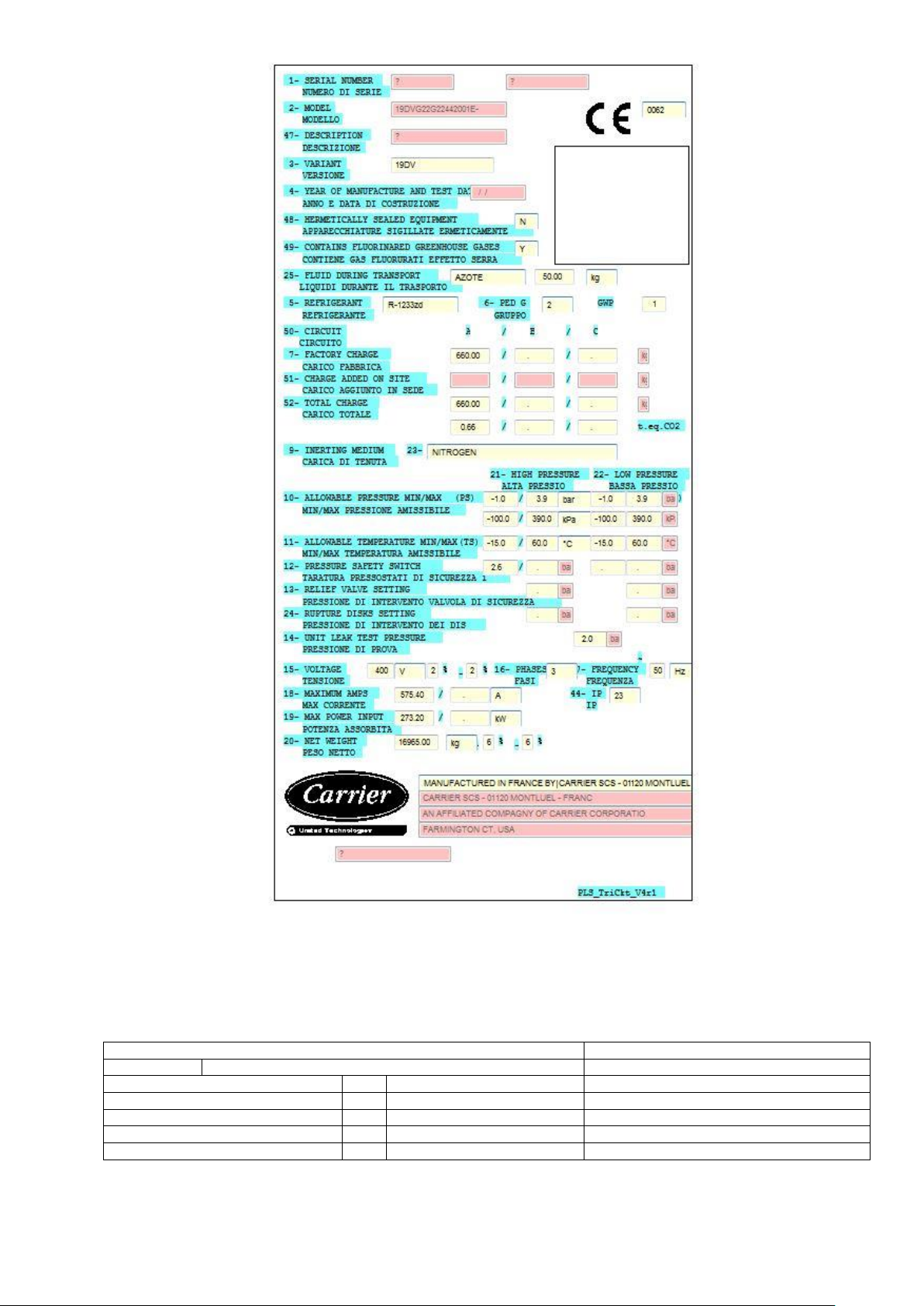
Fig 14 – Example of chiller serial plate
High pressure side
Low pressure side
Min Max.
Min Max.
PS (see in the list above)
kPa
-100 390
-100 390
TS (see in the list above)
°C
-15 60
-15 60
Pressure switch cut-out pressure
kPa
262
Relief valve cut-out pressure
kPa
500
500
Test pressure, unit leak test
kPa
200
200
Check all items against shipping list. Immediately notify the nearest Carrier representative if any item is missing.
32
Page 33
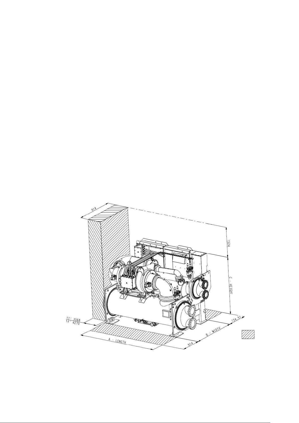
3.2.3 Installation requirements
Prior to starting the chiller’s electrical installation, certain requirements should be checked. Input power wire sizes,
branch circuit protection, and control wiring are all areas that need to be evaluated.
Conduit Entry Size — It is important to determine the size of the conduit openings in the enclosure power entry
plate so that the wire planned for a specific entry point will fit through the opening. Do NOT punch holes or drill into
the top surface of any panels. Knockouts are provided on the enclosure. The VFD entry plate is designed to be
removed before any holes are made to prevent particulate from entering the cabinet.
Recommended Control and Signal Wire Sizes — The recommended minimum size wire to connect I/0 signals to
the control terminal blocks is 0.75 mm2.
Recommended Airflow Clearances — Be sure there is adequate clearance for air circulation around the enclosure.
152.4 mm minimum clearance is required wherever vents are located in an enclosure.
Service Clearances — Verify that there are adequate service clearances as identified in Fig. 15.
Match Power Module Input and Supply Power Ratings — It is important to verify that building power will meet the
input power requirements of the Machine Electrical Data nameplate input power rating. Be sure the input power to
the chiller corresponds to the chiller’s nameplate voltage, current, and frequency and to the design data sheet
provided by the equipment salesman. Verify all electrical inputs against design data sheets.
Fig 15 – 19DV overhead service clearance
33
Page 34

3.2.4 Provide machine protection
Protect machine from construction dirt and moisture. Keep protective shipping covers in place until machine is
ready for installation. Do not keep the 19DV units outside where they are exposed to the weather.
If machine is exposed to freezing temperatures after water circuits have been installed, open waterbox drains and
remove all water from cooler and condenser. Leave drains open until system is filled.
It is important to properly plan before installing a 19DV unit to ensure that the environmental and operating
conditions are satisfactory and the machine is protected. The installation must comply with all requirements in this
document and in the certified prints.
3.2.5 Operating Environment
Chiller should be installed in an indoor environment where the ambient temperature is between 5 and 40°C with a
relative humidity of 95% or less, non-condensing. To ensure that electrical components operate properly, do not
locate the chiller in an area exposed to dust, dirt, corrosive fumes, or excessive heat and humidity.
3.3 Step 2 – Rig the machine
The 19DV machine can be rigged as an entire assembly. It also has connections that allow the compressor,
evaporator, condenser, VFD, an major accessories be separated for plant introduction under the supervision of
Carrier. Contact local Carrier office for details if separation is required.
3.3.1 - Rigging the complete machine
See rigging instructions on label attached to machine. Lift machine only from the points indicated in the
instructions supplied and in the machine rigging drawings. Each lifting cable or chain must be capable of
supporting the entire weight of the machine.
WARNING: Lifting machine from points other than those specified may result in serious damage to the unit and
personal injury. Rigging equipment and procedures must be adequate for machine weight. See table 2 for the
machine weights.
If the unit is disassembled for slinging, the weight of each element of the machine must be known: motor,
compressor, heat exchangers with and without refrigerant charge, electrical equipment, special water boxes, etc.
This information is available on the dimensional drawing supplied with the machine.
IMPORTANT: Only a qualified service technician should perform this operation.
WARNING: Do not attempt to disconnect flanges while the machine is under pressure. Failure to relieve pressure
can result in personal injury or damage to the unit.
CAUTION: Before rigging the compressor, disconnect all wires entering the control box.
IMPORTANT: Verify with company performing the rigging that they have access to required spreader beam for 4
point lift. Carrier is not responsible for rigging damage.
CAUTION: Factory-supplied insulation is not flammable but can be damaged by welding sparks and open flame.
Protect insulation with a wet canvas cover.
Each lifting cable or chain must be capable of supporting the entire weight of the machine.
Contractors are not authorized to disassemble any part of the chiller without Carrier’s supervision. Any request
otherwise must be approved in writing by the Carrier Technical Service Manager. Non-conformance to this
requirement may result in loss of product warranty.
NOTE: Carrier suggests that a structural engineer be consulted if transmission of vibrations from mechanical
equipment is of concern and is not the responsibility of the manufacturer.
Lifting chiller or components from points other than those specified may result in serious damage to the machine
or personal injury. Rigging equipment and procedures must be adequate for maximum chiller weight.
34
Page 35
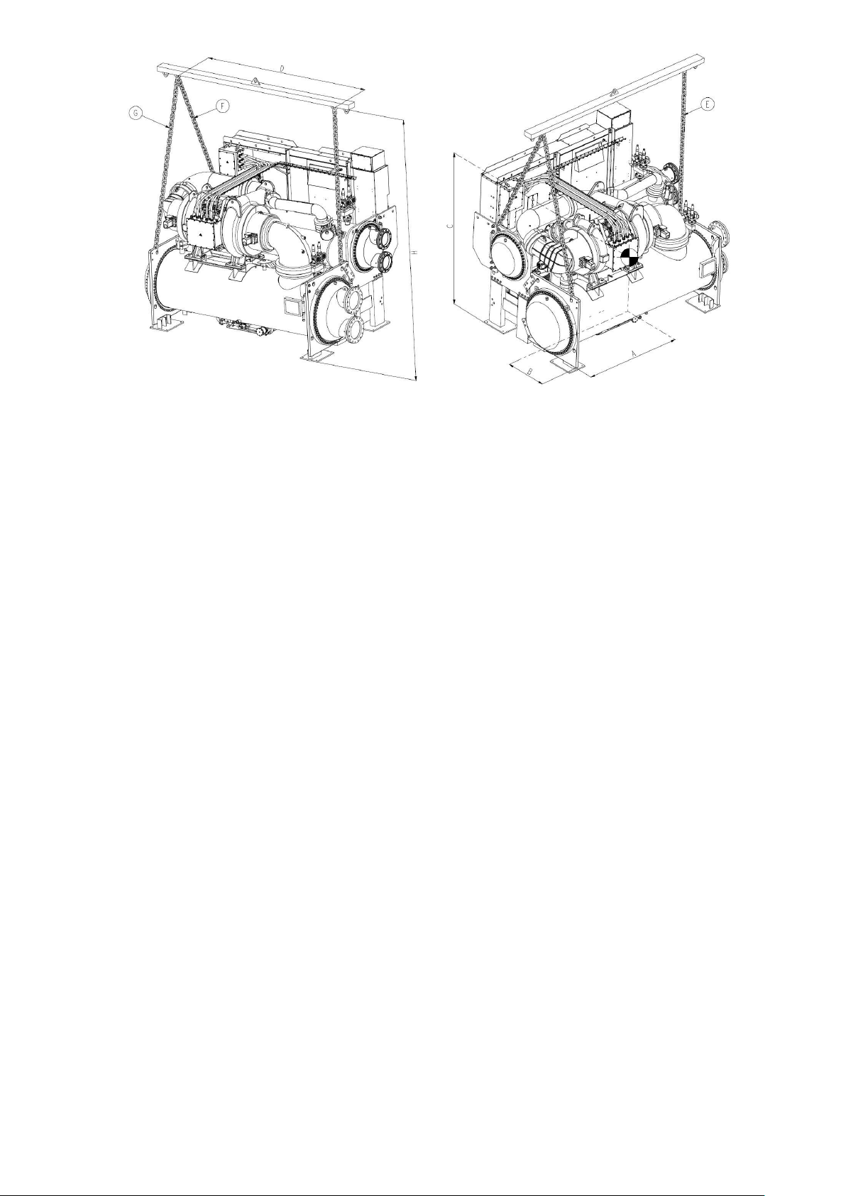
Fig 16 – Machine Rigging Guide (comp frame size DV4)
Notes :
1. Each chain must be capable of supporting the entire weight of the machine. See chart for maximum
weight. (The maximum weights shown cover weights from steel and copper tubing, insulation, and
refrigerant charge, excluding water weight.)
2. Chain lengths shown are typical for 4.5 m lifting height. Some minor adjustments may be required.
Dimensions A and B define distance from machine center of gravity to tubesheet outermost surfaces. Dim
“C” defines distance from machine c.o.g. to floor. Dim “D” defines distance measured between the chain a nd
lifting hooks.
3. Rigging can be different and specific if unit is equipped of special components or devices which
could have interference with chain way. Please refer always to the official dimensional drawings of
the ordered job and contact customer service to get more information for rigging.
IMPORTANT : Make sure that rigging cable is over the rigging bar before lifting.
35
Page 36
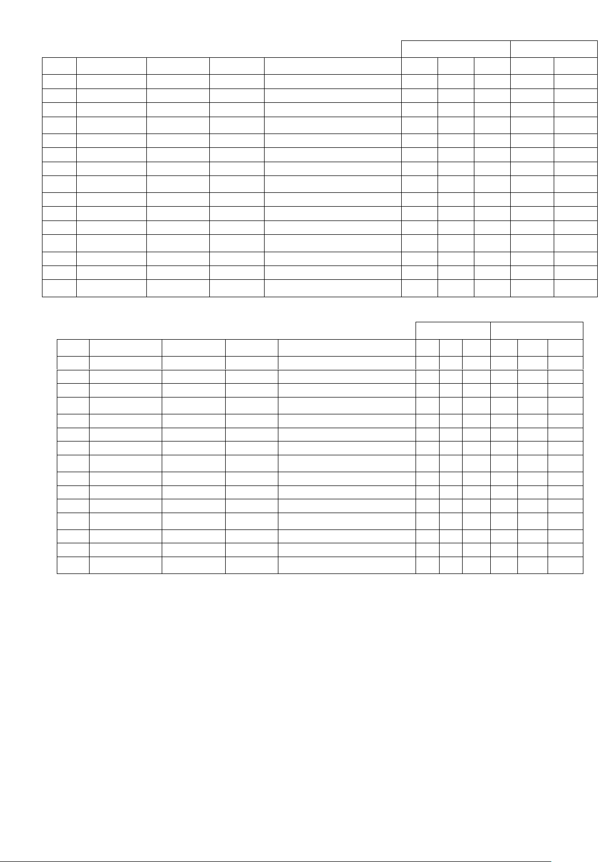
Overall max dimensions
(mm)
Weight max (kg)
Unit
model
heat exch. frame
Compr frame
Motor frame
Power VFD configuration
Length
Height
Width
Rigging
Operating
19DV
G2*G2* (12 feets)
02DV4
B, D,F, or H
VFD LF2 2CC (608 A)
4760
3190
3055
16500
18800
19DV
G2*G2* (12 feets)
02DV4
B, D,F, or H
VFD LF2 4AA (900 A)
4760
3190
3055
17390
19690
19DV
G2*G2* (12 feets)
02DV4
B, D,F, or H
VFD Danfoss E
* * *
16700
19000
19DV
G2*G2* (12 feets)
02DV4
B, D,F, or H
Control cabinet only (VFD not unit
mounted)
4760
2900
2585
15070
17370
19DV
G4*G4* (14 feets)
02DV4
B, D,F, or H
VFD LF2 2CC (608 A)
5275
3190
3055
17900
21350
19DV
G4*G4* (14 feets)
02DV4
B, D,F, or H
VFD LF2 4AA (900 A)
5275
3190
3055
18300
21750
19DV
G4*G4* (14 feets)
02DV4
B, D,F, or H
VFD Danfoss E
* * *
18100
21550
19DV
G4*G4* (14 feets)
02DV4
B, D,F, or H
Control cabinet only (VFD not unit
mounted)
5275
2900
2585
15970
19420
19DV
H2*H2* (12 feets)
02DV4
B, D,F, or H
VFD LF2 2CC (608 A)
4760
3330
3260
18290
20350
19DV
H2*H2* (12 feets)
02DV4
B, D,F, or H
VFD LF2 4AA (900 A)
4760
3330
3260
18660
20710
19DV
H2*H2* (12 feets)
02DV4
B, D,F, or H
VFD Danfoss E
* * *
18470
20530
19DV
H2*H2* (12 feets)
02DV4
B, D,F, or H
Control cabinet only (VFD not unit
mounted)
4760
3075
2790
16480
18610
19DV
H4*H4* (14 feets)
02DV4
B, D,F, or H
VFD LF2 4AA (900 A)
5195
3330
3260
19960
22980
19DV
H4*H4* (14 feets)
02DV4
B, D,F, or H
VFD Danfoss E
* * *
19760
22780
19DV
H4*H4* (14 feets)
02DV4
B, D,F, or H
Control cabinet only (VFD not unit
mounted)
5195
3075
2790
17630
20650
COG position (mm)
Rigging chain lengths
(mm)
Unit
model
heat exch. frame
Compr frame
Motor frame
Power VFD configuration
A B C D E
F
19DV
G2*G2* (12 feets)
02DV4
B, D,F, or H
VFD LF2 2CC (608 A)
1810
1135
1490
2500
2215
2670
19DV
G2*G2* (12 feets)
02DV4
B, D,F, or H
VFD LF2 4AA (900 A)
1800
1270
1470
2500
2150
2720
19DV
G2*G2* (12 feets)
02DV4
B, D,F, or H
VFD Danfoss E
* * *
2500
2210
2670
19DV
G2*G2* (12 feets)
02DV4
B, D,F, or H
Control cabinet only (VFD not unit
mounted)
1750
1240
1430
2500
2150
2720
19DV
G4*G4* (14 feets)
02DV4
B, D,F, or H
VFD LF2 2CC (608 A)
2020
1140
1470
2500
2215
2670
19DV
G4*G4* (14 feets)
02DV4
B, D,F, or H
VFD LF2 4AA (900 A)
2000
1270
1475
2500
2150
2720
19DV
G4*G4* (14 feets)
02DV4
B, D,F, or H
VFD Danfoss E
* * *
2500
2215
2670
19DV
G4*G4* (14 feets)
02DV4
B, D,F, or H
Control cabinet only (VFD not unit
mounted)
1965
1235
1435
2500
2150
2720
19DV
H2*H2* (12 feets)
02DV4
B, D,F, or H
VFD LF2 2CC (608 A)
1840
1060
1670
2380
2200
2570
19DV
H2*H2* (12 feets)
02DV4
B, D,F, or H
VFD LF2 4AA (900 A)
1820
1210
1690
2390
2110
2630
19DV
H2*H2* (12 feets)
02DV4
B, D,F, or H
VFD Danfoss E
* * *
2380
2200
2570
19DV
H2*H2* (12 feets)
02DV4
B, D,F, or H
Control cabinet only (VFD not unit
mounted)
1790
1005
1615
2390
2230
2550
19DV
H4*H4* (14 feets)
02DV4
B, D,F, or H
VFD LF2 4AA (900 A)
1990
1210
1660
2390
2110
2630
19DV
H4*H4* (14 feets)
02DV4
B, D,F, or H
VFD Danfoss E
* * *
2380
2200
2570
19DV
H4*H4* (14 feets)
02DV4
B, D,F, or H
Control cabinet only (VFD not unit
mounted)
1980
1015
1590
2380
2230
2550
* : not available, see official dim drawing
Table 2 – 19DV dimensions / rigging information
36
Page 37
Compressor components
Weight (kg)
Power Train Assembly(Include Motor Stator, Rotor Assembly and 2nd Stage Lube Support)
1000
2nd Stage lube support
75
Rotor Assembly (Include Motor Rotor, 1st Stage Lube Support)
310
1st Stage Lube Support
70
1st Stage Suction Assembly(Include 1st Stage Blade Ring, 1st Stage Suction Housing)
379
1st Stage Blade Ring Assembly
79
1st Stage Suction Housing
281
2nd Stage Suction Assembly(Include 2nd Stage Blade Ring, 2nd Stage Suction Housing)
351
2nd Stage Blade Ring Assembly
60
2nd Stage Suction Housing
274
1st Stage Volute
613
2nd Stage Volute
478
1st Stage Shroud
225
2st Stage Shroud
200
1st Stage IGV Shroud
54
2st Stage IGV Shroud
44
1st Stage Impeller
29
2st Stage Impeller
27
Miscellaneous
172
Total Weight (Excludes Motor Stator and Motor Rotor )
2810
COMPRESSOR FRAME
MOTOR CODE
STATOR & HOUSING WEIGHT
(kg)
ROTOR & SHAFT WEIGHT
(kg)
DV4
NB
494
150
DV4
ND
522
154
DV4
NF
558
159
DV4
NH
597
165
VFD type
Frame
Weight (kg)
LF2 Rockwell 608 Amps
2CC
1180
LF2 Rockwell 900 Amps
4AA
1590
Danfoss E 300
Table 3 - 19DV Compressor weights
Table 4 - 19DV motor weigths
Table 5 - 19DV VFD weights
37
Page 38
Frame size
Dry weight (kg)
Water weight (kg)
Frame size
Dry weight (kg)
Water weight (kg)
G20
4858
890
G2A
4672
896
G21
4936
925
G2B
4718
926
G22
5013
960
G2C
4769
960
G23
5091
995
G2D
4818
992
G24
5194
1042
G2E
4892
1040
G25
4858
890
G2F
4642
880
G26
4914
916
G2G
4685
908
G27
4992
951
G2H
4742
944
G28
5075
989
G2J
4804
984
G29
5165
1030
G2K
4862
1023
G40
5174
928
G4A
4961
935
G41
5264
968
G4B
5014
970
G42
5354
1008
G4C
5074
1008
G43
5444
1048
G4D
5130
1044
G44
5563
1101
G4E
5216
1099
G45
5174
928
G4F
4927
917
G46
5240
958
G4G
4977
949
G47
5329
998
G4H
5043
991
G48
5426
1041
G4J
5115
1035
G49
5530
1089
G4K
5182
1080
H20
6316
962
H2A
6060
953
H21
6402
1001
H2B
6117
991
H22
6486
1039
H2C
6184
1035
H23
6599
1090
H2D
6257
1083
H24
6712
1142
H2E
6335
1135
H25
6287
950
H2F
6041
943
H26
6371
988
H2G
6098
981
H27
6471
1033
H2H
6162
1023
H28
6566
1077
H2J
6227
1067
H29
6679
1129
H2K
6305
1118
H40
6812
1011
H4A
6518
1002
H41
6912
1055
H4B
6584
1045
H42
7009
1099
H4C
6662
1095
H43
7140
1158
H4D
6747
1149
H44
7271
1216
H4E
6838
1208
H45
6779
997
H4F
6496
989
H46
6876
1041
H4G
6563
1032
H47
6991
1092
H4H
6638
1080
H48
7102
1143
H4J
6714
1130
H49
7233
1201
H4K
6804
1189
Table 6 – 19DV Cooler weights
38
Page 39
Frame size
Dry weight (kg)
Water weight (kg)
Frame size
Dry weight (kg)
Water weight (kg)
G22
2845
611
G2C
2620
652
G23
2951
656
G2D
2708
707
G24
3068
705
G2E
2788
756
G27
2808
597
G2H
2594
638
G28
2902
637
G2J
2670
686
G29
3013
684
G2K
2752
736
G42
3065
667
G4C
2807
713
G43
3188
718
G4D
2909
775
G44
3322
773
G4E
3002
831
G47
3023
651
G4H
2777
697
G48
3131
696
G4J
2865
751
G49
3260
750
G4K
2961
808
H22
3446
760
H2C
3158
820
H23
3589
818
H2D
3262
883
H24
3743
882
H2E
3376
951
H27
3390
738
H2H
3109
793
H28
3526
795
H2J
3203
851
H29
3671
855
H2K
3311
916
H42
3759
831
H4C
3430
899
H43
3923
897
H4D
3550
971
H44
4100
970
H4E
3681
1049
H47
3694
806
H4H
3374
869
H48
3852
870
H4J
3483
934
H49
4018
939
H4K
3608
1009
Frame size
Steel weight (kg)
DV4
1204
Cooler
Condenser
Frame size
Steel weight (kg)
Water weight (kg)
Steel weight (kg)
Water weight (kg)
G
845
614
407
215 H 783
607
315
249
Table 7 - 19DV Condenser weights
Table 8 - 19DV Economizer weight
Table 9 - 19DV Std type Dish head water box weights
39
Page 40
Item
Weight (kg)
Suction piping
225
ICP (interstage connecting piping)
460
Discharge piping
70
Purge assy
60
Copper pipings
250
Control pannel
90
PIC5+ touch screen
10
Cable and cable tray
120
Condenser frame
Envelop control & piping (kg)
Liquid bypass & isolation valve (kg)
G
180
227
H
-
-
Table 10 - 19DV Piping and others weights
Table 11 - 19DV accessories weight (kg)
3.3.2 - Rigging the machine components
Refer to instructions Fig. 16 and Table 2 , and Carrier Certified Prints for machine component disassembly.
IMPORTANT: Only a qualified service technician should perform this operation.
WARNING: Do not attempt to disconnect flanges while the machine is under pressure. Failure to relieve pressure
can result in personal injury or damage to the unit.
NOTE: If the cooler, economizer, and condenser vessels must be separated, the heat exchangers should be kept level
by placing a support plate under the tube sheets. The support plate will also help to keep the vessels level and aligned
when the vessels are bolted back together.
NOTE: Wiring must also be disconnected. Label each wire before removal (see Carrier Certified Prints). In order to
disconnect the VFD from the machine, remove wiring between the VFD from the machine, remove wiring between
VFD and control panel, purge system and the main motor leads at the starter lugs. Remove all transducer and
sensor wires at the sensor. Clip all wire ties necessary to pull heat exchangers apart.
To Separate Evaporator and Condenser:
1. Place a support plate under each tube sheet leg to keep each vessel level.
2. Cut tubing between high side float chamber and motor/ VFD cooling.
3. Cut tubing between high side float chamber and lube assembly.
4. Disconnect the compressor discharge pipe.
5. Disconnect bolted connection between the low side float chamber and the evaporator.
6. Disconnect bolted economizer pipe between economizer and second stage compressor inlet.
7. Cut tubing between purge and compressor volute.
8. Cut tubing between purge regeneration line and motor drain.
9. Cover all openings.
10. Disconnect all wires and cables that cross from cooler side of the machine to the condenser side.
11. Disconnect the marriage brackets connecting the evaporator and condenser tubesheets (both ends).
To Separate the Compressor from the Evaporator:
1. Unbolt motor drain flange.
2. Unbolt suction pipe flange.
3. Unbolt discharge pipe flange.
4. Cut tubing from purge to compressor volute.
5. Disconnect O-ring face seal from bearing drain (near motor drain).
40
Page 41
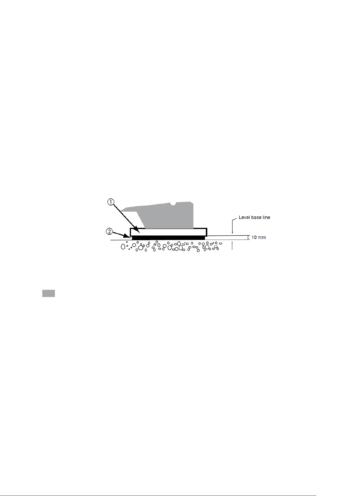
6. Cut bearing supply tubing from lube assembly.
7. Cut motor cooling supply line tubing from high side float chamber.
8. Disconnect inhibitor reclaim line running from compressor to near bottom of evaporator.
9. Disconnect all power and control wires connected to the compressor.
10. Cover all openings
11. Disconnect compressor motor power cables from VFD to motor.
12. Unbolt compressor mounting from the evaporator.
Additional Notes
1. Use silicone grease on new O-rings when refitting.
2. Use gasket sealant on new gaskets when refitting.
3.4 Step 3 – Install Machine Supports
Typical applications of these units are in refrigeration systems, and they do not require earthquake resistance.
Earthquake resistance has not been verified.
3.4.1 Install standard isolation
Figure X shows the position of support plates and shear flex pads, which together form the standard machine
support system.
Note: the isolation package includes four shear flex pads.
1.Support plate
2.Shear flex pad
: Machine foot
Fig 17 – Standard isolation
Important: Chiller housekeeping pad, anchor bolts, and attachment points that are designed by others must be in
accordance with all applicable national and local codes.
3.4.2 Installation of levelling accessory (if necessary)
Uneven floors or other considerations may dictate the use of accessory soleplates (supplied by Carrier for field
installation) and leveling pads. Refer to Fig 18.
Chiller support plates must be level within 1/4-in. (6 mm) from one end to the other.
Level machine by using jacking screws in isolation soleplates. Use a level at least 24-in. (600 mm) long.
For adequate and long lasting machine support, proper grout selection and placement is essential. Carrier
recommends that only pre-mixed, epoxy type, non-shrinking grout be used for machine installation.
Follow manufacturer’s instructions in applying grout.
1. Check machine location prints for required grout thickness.
2. Carefully wax jacking screws for easy removal from grout.
3. Grout must extend above the base of the soleplate and there must be no voids in grout beneath the plates.
4. Allow grout to set and harden, per manufacturer’s instructions, before starting machine.
5. Remove jacking screws from leveling pads after grout has hardened.
41
Page 42
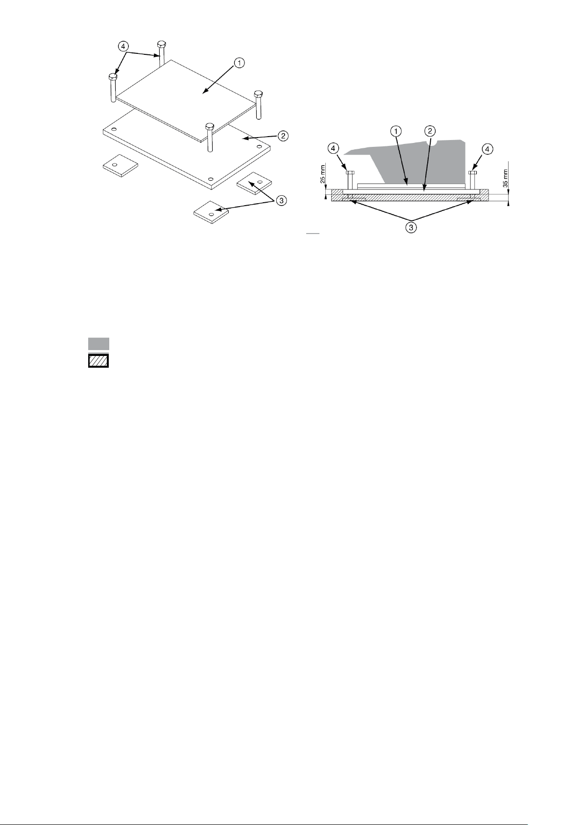
1. Accessory spring isolator
2. Soleplate (accessory) attaches securely to isolator
3. Level foundation
4. Adjusting screws
Note : Accessory (Carrier supplied, field-installed) soleplate package includes 4. Thickness of grout will
vary depending on the amount necessary to level chiller.Use only pre-mixed non-shrinkink grout.
Masterflow 648CP-Plus or Chemrex Embeco 636 Plus Grout 38 to 57 mm thick.
: Machine foot (side view)
: System base (concrete)
Fig 18 – Levelling accessory for 19DV units
42
Page 43
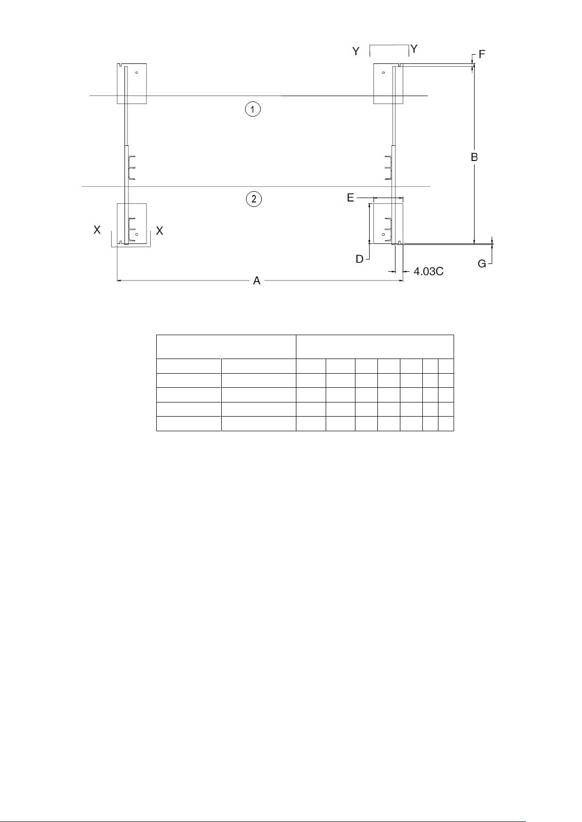
1 : Condenser
19DV heat exchanger size
Dimensions ( mm)
COOLER
CONDENSER
A B C D E F G
G2
G2
3951
2508
102
559
406
38
13
G4
G4
4472
2508
102
559
406
38
13
H2
H2
3951
2612
102
559
406
38
13
H4
H4
4472
2612
102
559
406
38
13
2 : Cooler
Fig 19 – 19DV footprint
Note: X-X dimension refers to accessory soleplate. See fig 20.
Those dimensions are standard. Please always refer to the certified dimensional drawings supplied with the unit.
43
Page 44
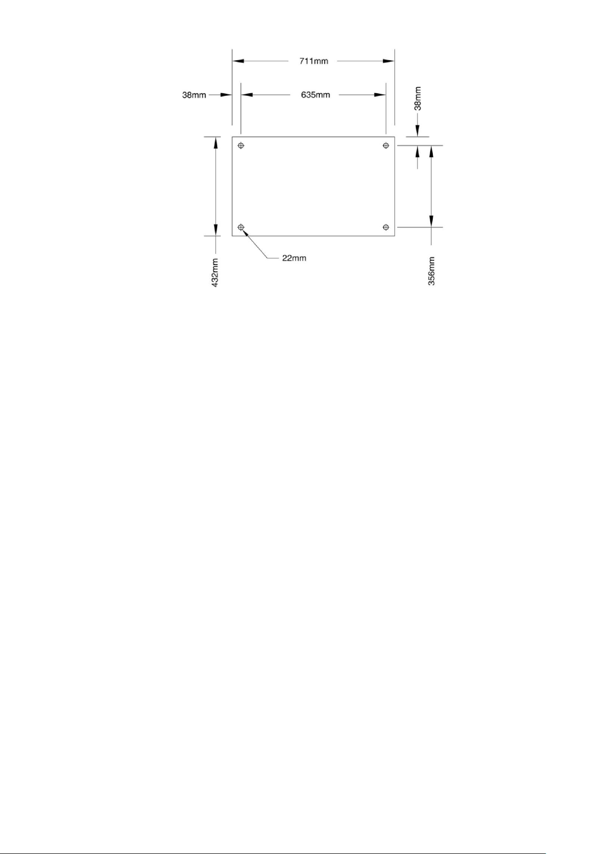
Fig 20 – Soleplate dimensions
3.4.3 Installation of spring isolation system
Spring isolation may be purchased as an accessory from Carrier for field installation. It may also be field supplied
and installed. Spring isolators may be placed directly under machine support plates or located under machine
soleplates. See Fig. 21 . Low profile spring isolation assemblies can be field supplied to keep the machine at a
convenient working height.
Obtain specific details on spring mounting and machine weight distribution from job data. Also, check job data for
methods to support and isolate pipes that are attached to spring isolated machines.
NOTE: The springs are designed to support the weight of the chiller only. Connected piping must be supported
independently of the chiller.
NOTE: It is recommended that any installation other than the ground floor should have spring isolation for the
chiller and piping.
NOTE: These isolators are not intended for seismic duty, but are intended to reduce the vibration and noise levels
transmitted from the chiller to the surrounding environment. For installations adjacent to areas that are sensitive to
noise and/or vibration, use the services of a qualified consulting engineer or acoustics expert to determine whether
these springs will provide adequate noise/vibration suppression.
44
Page 45
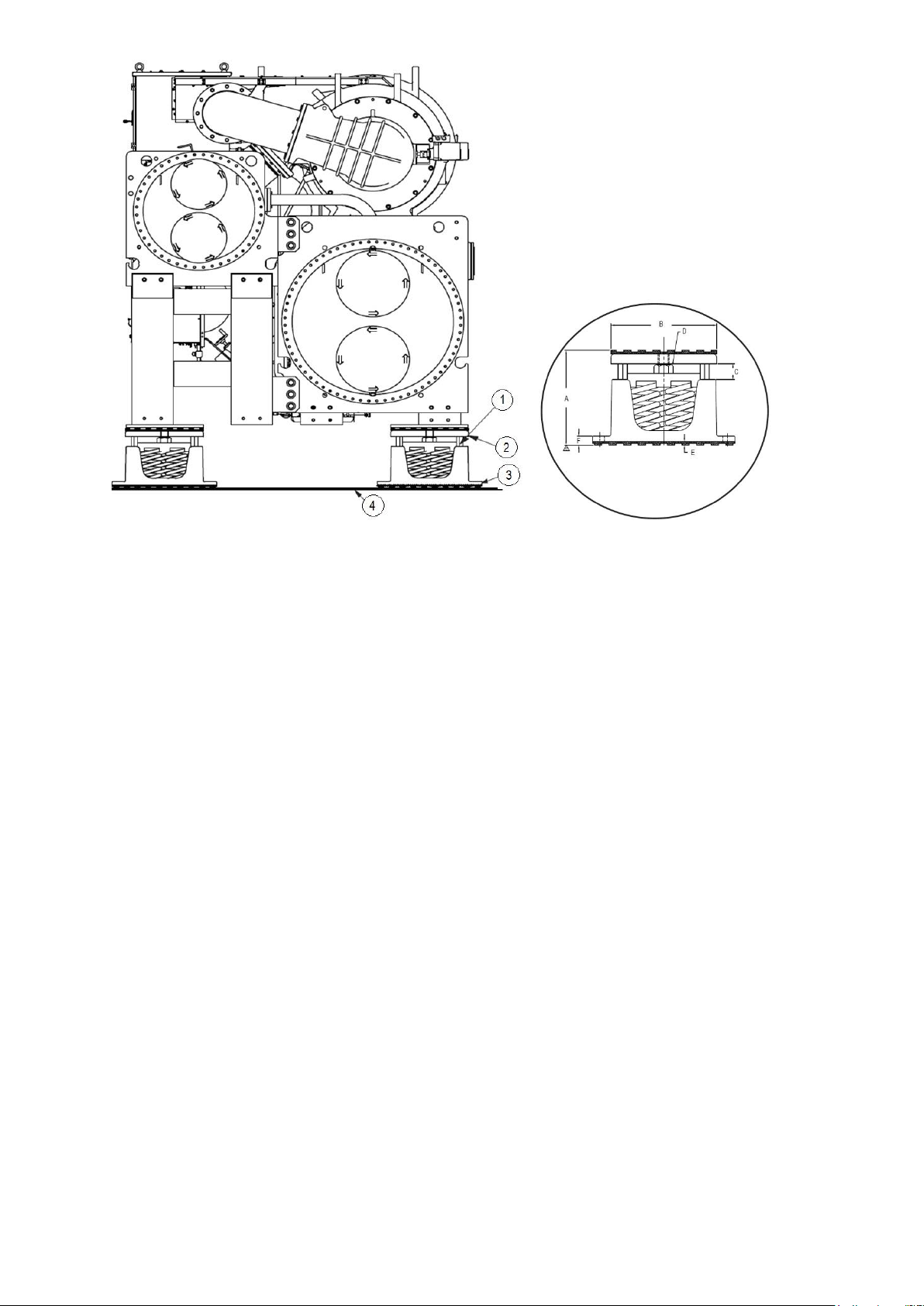
1 : Accessory spring isolator
2, 3 : Resilient sheer flex pad, bonded to top and bottom of spring amount
4 : Level foundation
A : 168 mm free height
B : 184 mm
C : 6 to 13 mm gap
D : Adjusting bolt
E : 6 mm elastomeric pad top & bottom
F : 16 mm
NOTES:
1. For spring installation follow manufacturer’s instructions.
Set chiller on all springs in one rig; jacking one end out of level will result in excess loading on springs and may cause damage.
2. The accessory spring isolators are supplied by Carrier for installation in the field if the accessory is purchased.
Fig 21 – Spring isolation installation
3.5 Step 4 – Connection of water, vent and purge piping
For size and position of the heat exchanger water inlet and outlet connections refer to the certified dimensional
drawings supplied with the unit. See. Fig. 22 - “Standard waterboxes and nozzle arrangements” The water pipes
must not transmit any radial or axial force nor any vibration to the heat exchangers.
The water supply must be analyzed and appropriate filtering, treatment, control devices, isolation and bleed valves
and circuits built in, to prevent corrosion, fouling and deterioration of the pump fittings. Consult either a water
treatment specialist or appropriate literature on the subject.
45
Page 46
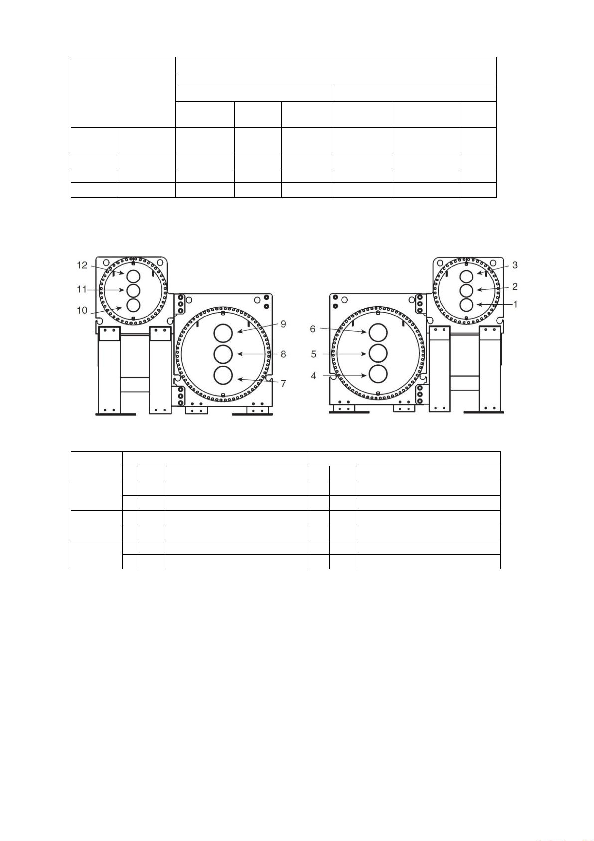
Heat exchanger
frame size
Nozzle size (mm)
(Nominal size)
Cooler
Condenser
1 pass
2 pass
3 pass
1 pass
2 pass
3
pass
G-G
NIH
356
(DN350)
356
324
(DN300)
324
273
(DN250)
273 MWB
356
356
324
324
273
273
H-H
NIH
356
356
324
324
324
273 MWB
356
356
324
324
273
273
Pass
Evaporator waterboxes
Condenser waterboxes
In
Out
Arrangement code*
In
Out
Arrangement code*
1
8
5
A
11
2 P 5
8 B 2
11
Q
2
7
9 C 10
12 R 4
6 D 1
3
S
3
7
6 E 10
3 T 4
9 F 1
12
U
Table 12 – 19DV nozzle size
* : Refer to certified drawings
3.5.1 Install water piping to heat exchanger
Install piping using job data, piping drawings, and procedures outlined below. A typical piping installation is
shown in Fig. 23.
CAUTION: Factory-supplied insulation is not flammable but can be damaged by welding sparks and open flame.
Protect insulation with a wet canvas cover.
CAUTION: To prevent damage to sensors, remove evaporator and condenser water temperature sensors before
welding connecting piping to water nozzles. Replace sensors after welding is complete.
Fig. 22 - “Standard waterboxes
and nozzle arrangements”
46
Page 47
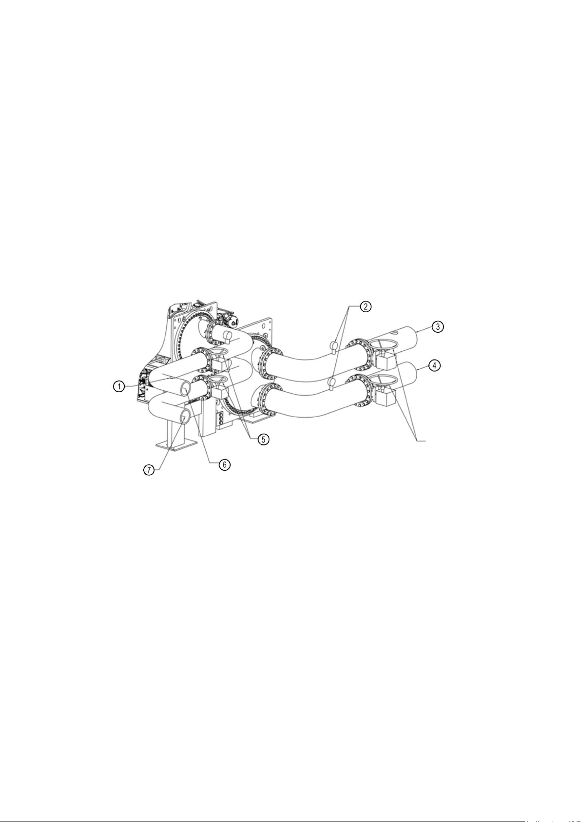
CAUTION: When flushing the water systems, isolate the chiller from the water circuits to prevent damage to the
heat exchanger tubes.
1 - Offset pipe flanges to permit removal of waterbox cover for maintenance and to provide clearance for pipe
cleaning. No flanges are necessary with marine waterbox option; however, water piping should not cross in front
of the waterbox or compressor because service access will be blocked.
2 - Provide openings in water piping for required pressure gages and thermometers. For thorough mixing and
temperature stabilization, wells in the leaving water pipe should extend inside pipe at least 2 in. (50 mm).
3. Install air vents at all high points in piping to remove air and prevent water hammer.
4. Field-installed piping must be arranged and supported to avoid stress on the equipment and transmission of
vibration from the equipment. Piping must be installed to prevent interference with routine access for the reading,
adjusting, and servicing of the equipment. Provisions should be made for adjusting the piping in each plane for
periodic and major servicing of the equipment.
5. Water flow direction must be as specified in Fig. 23.
NOTE: Entering water is always the lower of the 2 nozzles. Leaving water is always the upper nozzle for evaporator
or condenser for two and three pass arrangements.
1 : Air vent
2 : Pressure gages
3 : Leaving chilled water
4 : Entering chilled water
5 : Isolation valves
6 : Leaving condenser water
7 : Entering condenser water
Note: It is also strongly recommended to install 1-inch diameter connection points with valves on each
customer side water pipe. These connection points are used to connect an heating device (water heatpump)
on closed loop to warm the water inside the cooler or condenser in case of refrigerant retrieving.
Fig 23 – Typical nozzle piping (not supplied by Carrier)
6. Install waterbox vent and drain piping in accordance with individual job data. Consult certified drawings for
connection size.
7. Install waterbox drain plugs in the unused waterbox and vent openings..
8. Isolation valves are recommended on the cooler and condenser piping to each chiller for service. The isolation
valves should allow for piping between the valves and chiller to be removed without draining the system fluid.
9. Apply appropriate torque on the retaining bolts in a crisscross pattern for the water box covers before insulating
the water box cover. The gasket can relax during transportation and storage and the water box cover requires
retightening of the bolts during installation.
47
Page 48

3.5.2 Install vent piping to relief devices
If the relief valves are installed on a change-over manifold, this is equipped with a relief valve on each of the two
outlets. Only one of the two relief valves is in operation, the other one is isolated. Never leave the change-over valve
in the intermediate position, i.e. with both ways open (Bring the actuator in abutment, front or back according to the
outlet to isolate). If a relief valve is removed for checking or replacement please ensure that there is always an active
relief valve on each of the change-over valves installed in the unit.
All factory-installed relief valves are lead-sealed to prevent any calibration change. The external safety valves are
designed and installed to ensure damage limitation in case of a fire. In accordance with the regulations applied for
the design, the European directive on equipment under pressure and in accordance with the national usage
regulations:
• These safety valves are not safety accessories but damage limitation accessories in case of a fire,
• The high pressure switches are the safety accessories.
The relief valve must only be removed if the fire risk is fully controlled and after checking that this is allowed by
local regulations and authorities. This is the responsibility of the operator.
The external safety valves must in principle be connected to discharge pipes for units installed in a room. Refer to
the installation regulations, for example those of European standards EN 378 and EN 13136.
If a safety valve is replaced, do not leave the machine without safety valves. Only remove the safety valve, if the
risk of fire is completely controlled and under the responsibility of the user. Only one safety valve at a time must be
removed and replaced so that fire protection is maintained during this operation. Please refer to “Safety
considerations”.
Vent relief devices to the outdoors in accordance with the applicable national standard (for example, NFE 35400 in
France and EN 378 when applicable) for the safety of chilling devices as well as any other applicable codes.
DANGER: Refrigerant discharged into confined spaces can displace oxygen and cause asphyxiation.
If relief devices are manifolded, the cross-sectional area of the relief pipe must at least equal the sum of the areas
required for individual relief pipes.
Provide a pipe plug near outlet side of each relief device for leak testing. Provide pipe fittings that allow vent piping
to be disconnected periodically for inspection of valve mechanism.
Piping connected to relief devices must not apply stress to the device. Adequately support piping. A length of flexible
tubing or piping near the device is essential on spring isolated machines.
Cover the outdoor vent with a rain cap and place a condensation drain at the low point in the vent piping to
prevent water build-up on the atmospheric side of the relief device.
Equip the piping with connections to allow disconnection of the piping for inspection.
See figure 2, item 20 and 21 for relief valves location.
3.5.3 Purge discharge
Purge discharge shall be connected to the safety valve vent line assembly with 9.6 mm flare connection to the
discharge line from purge unit.
See figure 10, item 10 for purge discharge location.
3.6 Step 5 – Electrical connection
Field wiring must be installed in accordance with job wiring diagrams and all applicable electrical codes.
CAUTION:
Do not run any hazardous voltage wiring in the control panel sections associated with extra-low voltage wiring.
Damage to machine could occur as a result.
Do not run 50 volt or higher wiring into the PIC5+ Touch screen Panel and Control Panel. The panel should only
be used for low voltage wiring (50V max).
Wiring diagrams in this publication are for reference only and are not intended for use during actual installation;
follow job specific wiring diagrams.
CAUTION:
Do not attempt to start compressor or any motor (even for a rotation check) or apply test voltage of any kind to the
VFD or motor while the chiller is under a dehydration vacuum. Motor insulation breakdown and serious damage
may result.
48
Page 49
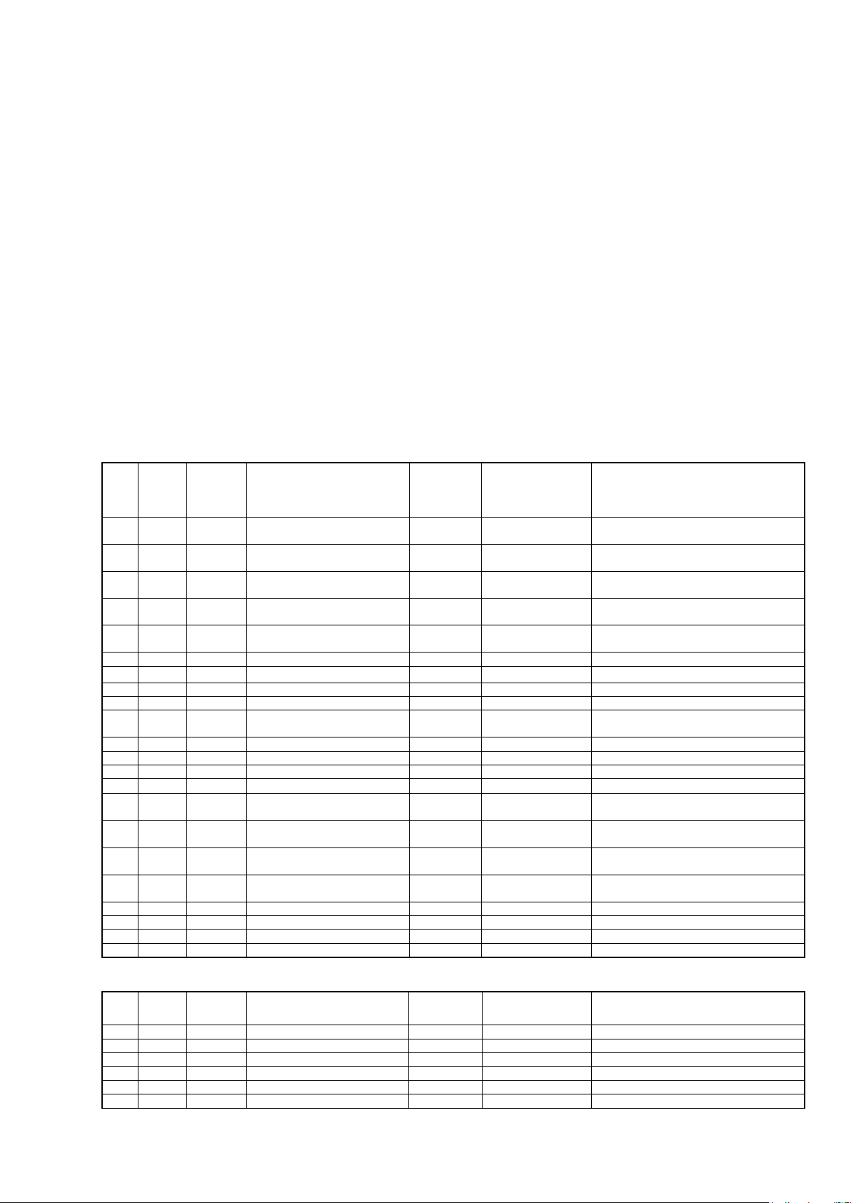
IOB1
BLOCK
Terminal
#
Point Description
Point name
Designation for
wiring diagram
Comments
AI1
J16
1-5
Entering chilled water
temperature
ECW
RT1
AI2
J16
2-6
Leaving chilled water
temperature
LCW
RT2
AI3
J16
3-7
Entering condenser water
temperature
ECDW
RT7
AI4
J16
4-8
Leaving condenser water
temperature
LCDW
RT8
AI5
J15
6-12
Evap. refrigerant liquid
temperature
EVAP_T
RT15
AI6
J15
5-11
Comp Discharge temperature
DGT
RT21
AI7
J15
4-10
Condenser pressure
COND_P
BP1
AI8
J15
3-9
Evaporator pressure
EVAP_P
BP3
AI9
J15
2-8
AI10
J15
1-7
FS VFD Load current
VFDC_MA
-
For freestanding VFD option - customer
terminals
AI11
J10
1-7
AO1
J14
1-4
Chiller Status Output mA
CHST_OUT
Chiller status
used in std
AO2
J14
2-5
AO3
J14
3-6
DI1
J13
1-5
Evap Water Flow Switch
EVAP_FS
-
User option, dry contact "Closed"
indicates "Flow" / not connected in std
DI2
J13
2-6
Cond Water Flow Switch
COND_FS
-
User option, dry contact "Closed"
indicates "Flow" / not connected in std
DI3
J13
3-7
Remote contact input
REM_CON
Remote on/off
User option, dry contact "Closed"
indicates Turn ON chiller
DI4
J13
4-8
Remote emergency stop input
E_STOP
Remote emergency
stop
User option, dry contact "Closed"
indicates Chiller Emergency stop
DO1
J12
6-7
Economizer bypass valve
ECBY_VLV
EBPV
Factory option
DO2
J12
9-10
Refrigerant Pump
REF_PUMP
KM1233
DO3
J12
1-2
Chiller Alarm Relay
ALM
K112
DO4
J12
4-5
Vapor Venting Line SV
VAPL_SV - not used / special
IOB2
BLOCK
Terminal
#
Point Description
Point name
Designation for
wiring diagram
Comments
AI1
J16
1-5
Motor winding temperature 1
MTRW1
RT31C
AI2
J16
2-6
AI3
J16
3-7
EC valve feedback Ma
HGBP_MA
Y11 13-14
factory option / 4 - 20 mA
AI4
J16
4-8
AI5
J15
6-12
Pump Outlet Pressure
PUMPO_P
BP81
AI6
J15
5-11
Bearing Outlet pressure
BRGO_P
BP71
NOTE: The dry contacts for the field inputs should be located as close to the unit as possible. The field wiring
should be capable of preventing electrical noise or induced voltage and should not be routed with any wires with
voltage over 50 v.
3.6.1 CONNECT CONTROL INPUTS
Wiring may be specified for a spare safety switch, and a remote start/stop contact can be wired to the terminal
strip. Additional spare sensors and control modules may be specified as well. Carrier Comfort Network® (CCN)
communication is wired to the machine HMI panel.
Wiring may be specified for a remote start/stop contact, a remote emergency stop contact, an ice build contact, a
spare safety switch, a power request feedback switch, a cooler water flow switch and a condenser water flow
switch can be wired to the control panel field terminal strip. Additional spare sensors may be specified for auto
demand limit input, refrigerant leak sensor, common CHWS temperature sensor, auto water temp reset and
common CHWR temp sensor can be wired to the control panel field terminal strips as well. These are wired to the
machine control panel. See electrical wiring diagrams.
3.6.2 CONNECT CONTROL OUTPUTS
Wiring maybe specified for a chiller alarm relay, a free cooling mode relay and a power request relay can be wired
to the control panel field terminal strip. Additional analog output signals may be specified for chiller running status
(on/off/ready) and head pressure output can be wired to the control panel field terminal strips as well. These are
wired to the machine control panel. See electrical wiring diagrams.
49
Page 50
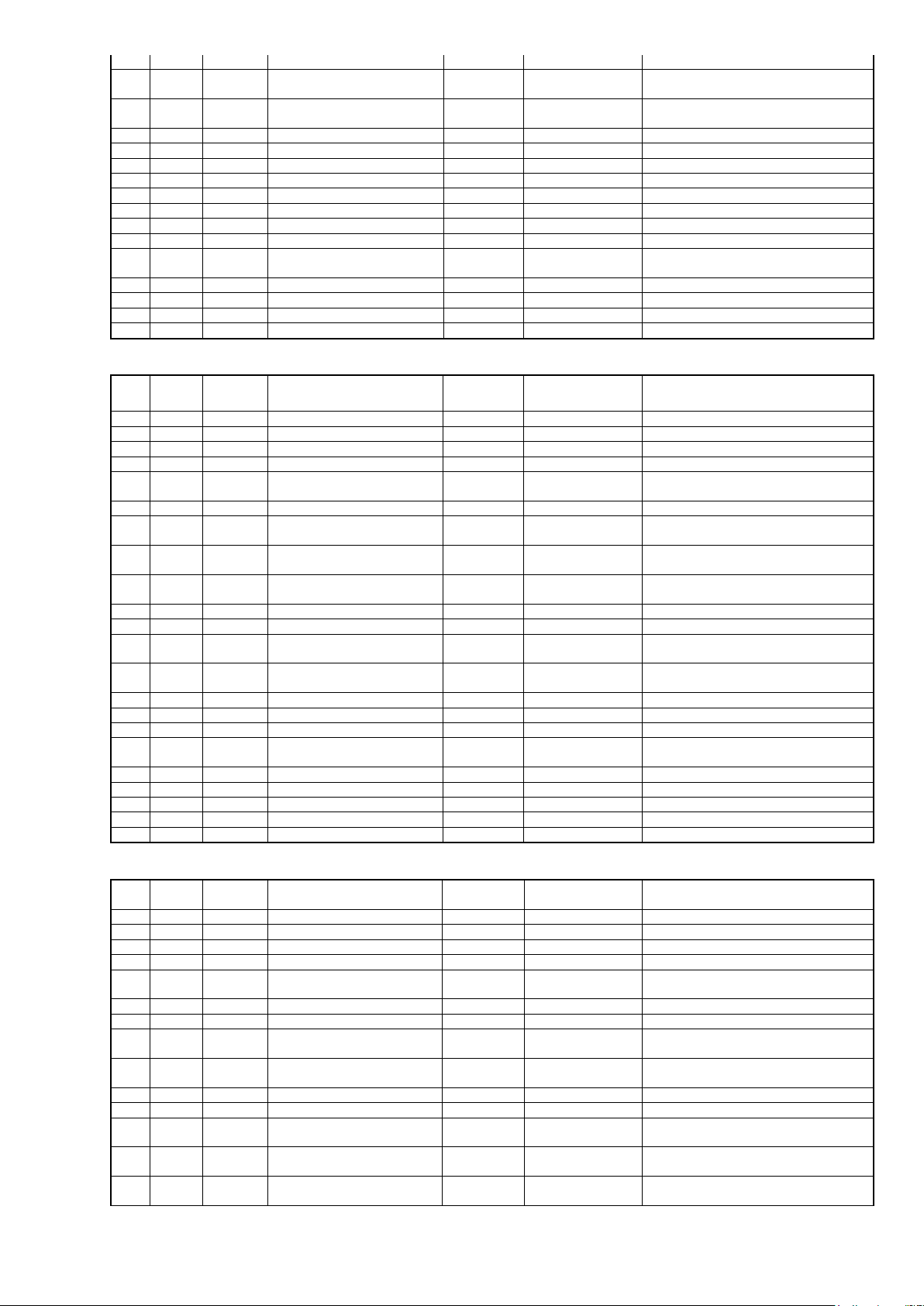
AI7
J15
4-10
Bearing inlet pressure
BRGI_P
BP70
AI8
J15
3-9
Auto Demand limit input
AUTO_DEM
Auto demand limit
User option, 4-20 mA - customer
terminals
AI9
J15
2-8
Refrigerant leak sensor
REF_LEAK
User option, 4-20 mA / not connected in
std
AI10
J15
1-7
Pump inlet Pressure
PUMPI_P
BP80
AI11
J10
1-7
AO1
J14
1-4
Guide Vane1 output
GV1_OUT
M67 3-4
AO2
J14
2-5
AO3
J14
3-6
EC Valve Output mA
HGBP_OUT
Y11 15-16
factory option / 4 - 20 mA
DI1
J13
1-5
DI2
J13
2-6
Liquid Level Switch
HF_LS
HF_LS
DI3
J13
3-7
High Pressure Switch
HP_SW
K2
contact NO coming from Safety relay
DI4
J13
4-8
Ice build contact
ICE_CON
User option, dry contact / not connected
in std
DO1
J12
6-7
Condenser Control Valve
COND_CV
CCV1
DO2
J12
9-10
Evaporator Control Valve
EVAP_CV
ECV1
DO3
J12
1-2
Condenser Filling Valve
COND_FCV - Option
DO4
J12
4-5
Economizer Isolation Valve
ECON_IV - Option
IOB3
BLOCK
Terminal
#
Point Description
Point name
Designation for
wiring diagram
Comments
AI1
J16
1-5
1st stage Bearing Temp
CBH1_T
RT39C
with spare
AI2
J16
2-6
2nd stage Bearing temp
CBH2_T
RT40C
with spare
AI3
J16
3-7
Bearing Ref Supply Temp
BRGI_T
RT41
AI4
J16
4-8
Guide Vane 2 Actual Pos
GV2_POS
M69 5-6
AI5
J15
6-12
Remote Reset Sensor
R_RESET
Remote reset
sensor
User option, 5K thermistor / connected
on terminals
AI6
J15
5-11
Guide Vane 1 Actual Pos
GV1_POS
M67 5-6
AI7
J15
4-10
Common CHWS Temp
CHWS_T
Common CHWS
Temp
Used for lead lag option / connected on
terminals
AI8
J15
3-9
Auto Water Temp Reset
AUTO_RES
Auto Chiller Water
Temp Reset
User option, 4-20 mA / connected on
terminals
AI9
J15
2-8
Common CHWR Temp
CHWR_T
Chiller CHWR
Temp
Used for lead lag option
AI10
J15
1-7
AI11
J10
1-7
AO1
J14
1-4
Head Pressure Output
HDPV_OUT
Condenser sea
water valve
4 - 20 mA / connected on terminals
AO2
J14
2-5
Head Pressure Output 2
HDPV_OU2
-
4- 20 mA / Not used yet but can be
used
AO3
J14
3-6
Guide Vane 2 Output
GV2_OUT
M69 3-4
DI1
J13
1-5
DI2
J13
2-6
DI3
J13
3-7
Spare safety
SAFETY
Spare safety
User option, dry contact NO /
connected on terminals
DI4
J13
4-8
DO1
J12
6-7
Evaporator Drain Valve
EVAP_DCV
-
Not used with new design lubrication
DO2
J12
9-10
Condenser Drain Valve
COND_DCV
-
Not used with new design lubrication
DO3
J12
1-2
Chilled water pump
CHWP - User option / not connected
DO4
J12
4-5
Condenser water pump
CDWP - User option / not connected
IOB4
BLOCK
Terminal
#
Point Description
Point name
Designation for
wiring diagram
Comments
AI1
J16
1-5
AI2
J16
2-6
AI3
J16
3-7
Entering Evap water pressure
EVAP_EWP
BP13
User option
AI4
J16
4-8
Leaving Evap water pressure
EVAP_LWP
BP12
User option
AI5
J15
6-12
Entering Cond water
pressure
COND_EWP
BP15
User option
AI6
J15
5-11
Leaving Cond water pressure
COND_LWP
BP14
User option
AI7
J15
4-10
AI8
J15
3-9
Evap water flow
measurement
EVAP_FL
-
User option, 4-20 mA / not connected in
std
AI9
J15
2-8
Cond water flow
measurement
COND_FL
-
User option, 4-20 mA / not connected in
std
AI10
J15
1-7
AI11
J10
1-7
AO1
J14
1-4
Chilled Water Pump
(Variable)
CHWP_V
Evaporator pump
control
User option, 4-20 mA / 0-5 V /
connected on terminals
AO2
J14
2-5
Condenser Water Pump
(Variable)
CDWP_V
Condenser pump
control
User option, 4-20 mA / 0-5 V /
connected on terminals
AO3
J14
3-6
Tower Fan (Variable)
TOW_FAN
-
User option, 4-20 mA / 0-5 V / not
connected in std
50
Page 51
DI1
J13
1-5
DI2
J13
2-6
Power Request Feedback
POW_FDB
Power Available
Marine option
DI3
J13
3-7
Customer Alert
CUS_ALE
ICCP 7-8
Marine option, dry contact, NO,
connected on terminals to ICCP
DI4
J13
4-8
Freecooling Start Switch
FC_SS
SW2
Marine option, dry contact
DO1
J12
6-7
Free Cooling Mode
FC_MODE
K120
Factory option
DO2
J12
9-10
Power Request Output
POW_REQ
Power Request
Output
Marine option
DO3
J12
1-2
Tower Fan High
TFR_HIGH
-
User option / not connected in std
DO4
J12
4-5
Tower Fan Low
TFR_LOW
-
User option / not connected in std
Point description
Type
Terminal
identification -
TB5
Power supply 24AC for Digital Output
power supply
1-2
Chiller Alarm relay
Digital output
3-4
Chiller water pump
Digital output
9
Condenser water pump
Digital output
10
Tower fan high
Digital output
11
Tower fan low
Digital output
12
Feeback run
Digital output
13-14
Evaporator flow switch
Digital input
15-16
Condenser flow switch
Digital input
17-18
Remote contact input
Digital input
19-20
Emergency stop
Digital input
21-22
Ice build contact
Digital input
23-24
Spare safety
Digital input
25-26
Auto demand limit input
Analog input
35-36
Common CHWR Temp
Analog input
37-38
Autowater temp reset
Analog input
39-40
Common CHWS Temp
Analog input
41-42
Remote reset sensor
Analog input
43-44
Chiller status *
Analog output
45-46
Head pressure output
Analog output
47-48
Tower fan command signal
Analog output
53-54
Table 13 – PIC 5 – 19DV I/Os mapping list
* : chiller status in standard, %capacity load in option.
Table 14 – PIC 5 – 19DV I/Os terminal identification
51
Page 52
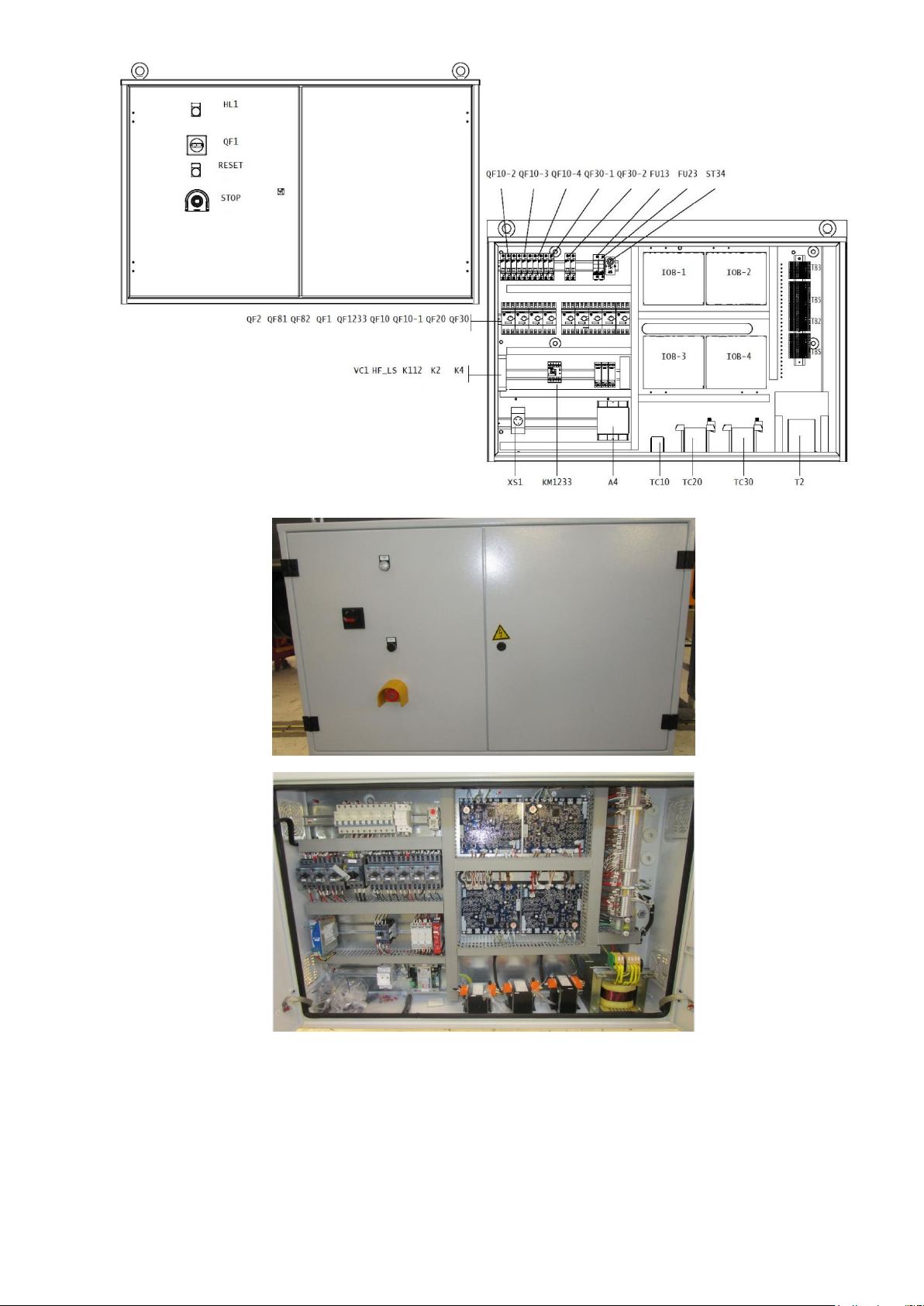
Fig 24 - 19DV control box
52
Page 53
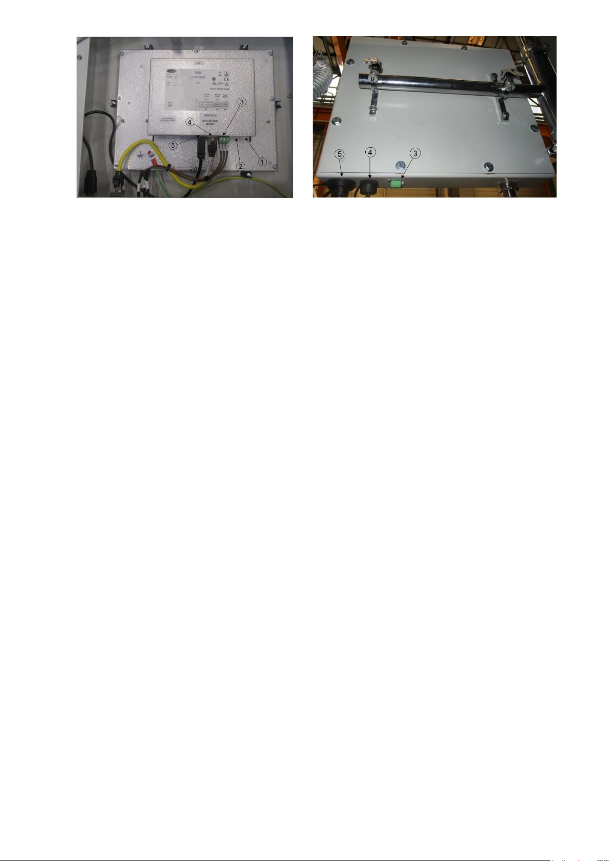
1 : Power supply 24V AC
2 : LEN
3 : CCN
4 : Ethernet
5 : USB
Fig 25 - 19DV HMI box rear view
53
Page 54
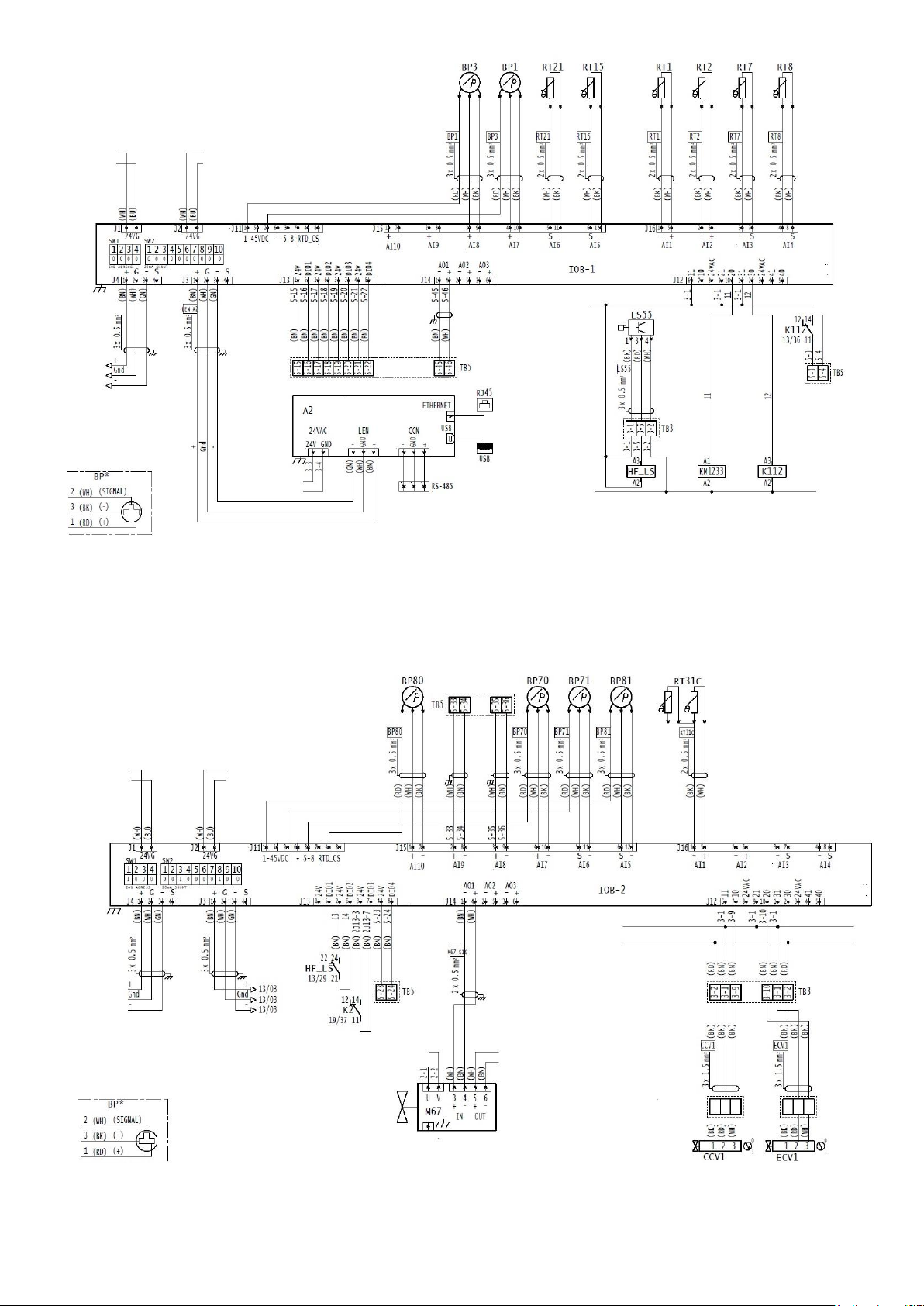
Fig 26 - 19DV – IOB1 wiring
Fig 27 - 19DV – IOB2 wiring
54
Page 55
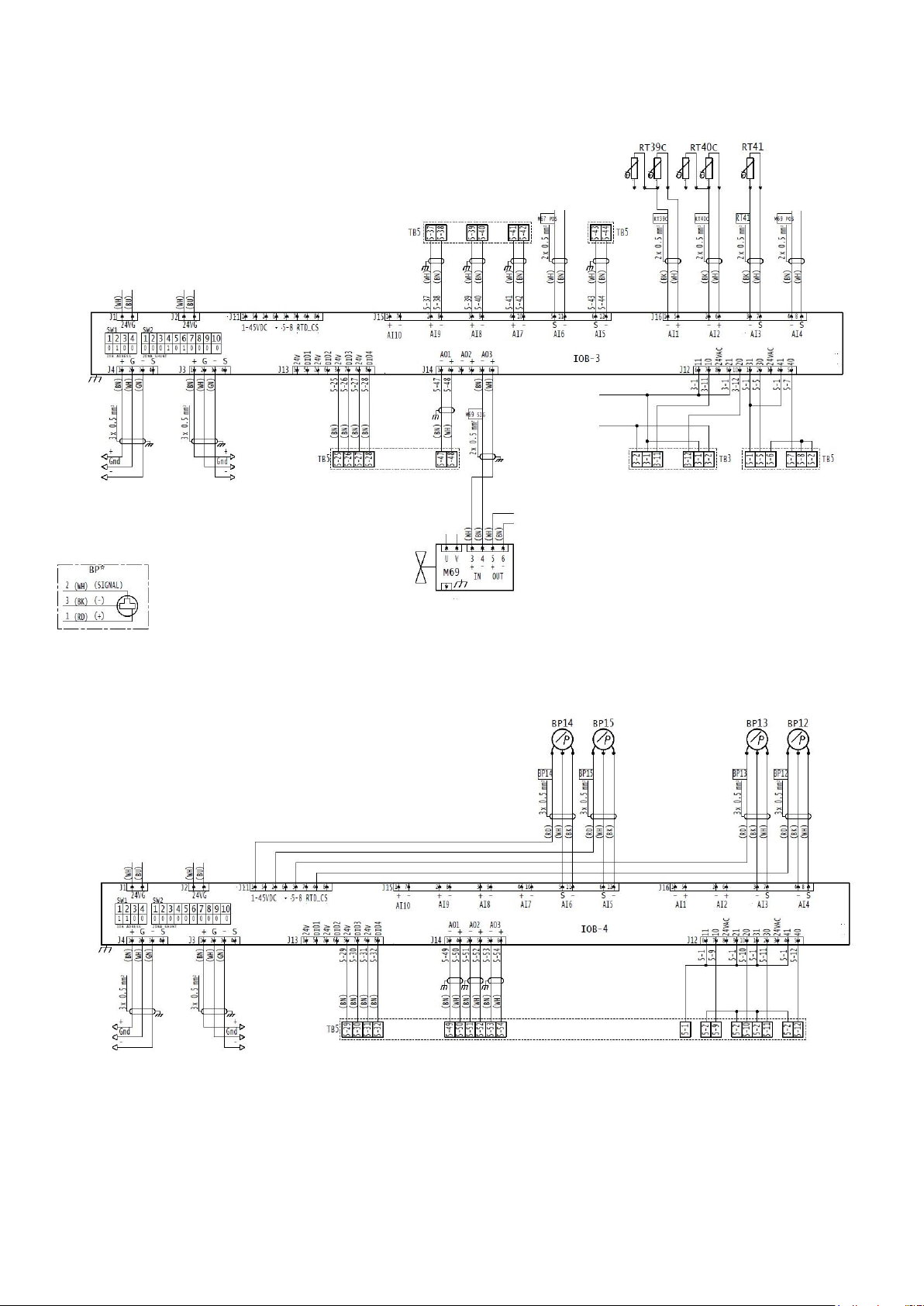
Fig 28 - 19DV – IOB3 wiring
Fig 29 - 19DV – IOB4 wiring
NOTE:
1. Field-supplied control connectors to be at least 0.75mm2 or larger. Supplied voltage of the wires in control
panel should be low (limited to 50V).
2. Each digital output loop shall be limited to a maximum of 1A AC RMS steady –stat @24Vac, high load relay is
recommended and the coil voltage of relay is 24VAC. Connect 5TB-1 to 3TB-1 and 5TB-2 to 3TB-2 for 24VAC
55
Page 56

power supply if total power consumes less than 40VA@20VAC. Others, power supply shall be provided by customer fused transformer.
3. The discrete input loop is powered by internal 24VAC power supply. Field optional contactor or switch must can
withstand rated 24VAC voltage, maximal 60mA and rated 20 mA current.
4. The analog input support 5kΩ/10kΩ NTC thermistor, 0/4-20mA sensor and 5VDC sensor.
5. Each analog output loop support 0/4-2OMA 0/2-10 VDC voltage output. The analog output loop is powered by
board. Do not supply external power.
6. For standard discrete input (on 1/2/3/4 IOB), only when the contactor switch is closed, an alarm will be
generated.
7. SW2 configured by field, if 4-20 mA signal sensor, shall turn the switch to “ON” position.
8. For 4thIOBdiscrete input, only when the contactor or switch is open, an alarm will be generated.
9. All the plug in the IOB use wire of 0.75mm2.
56
Page 57
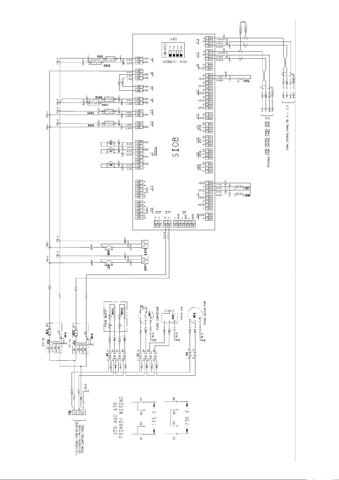
57
Page 58
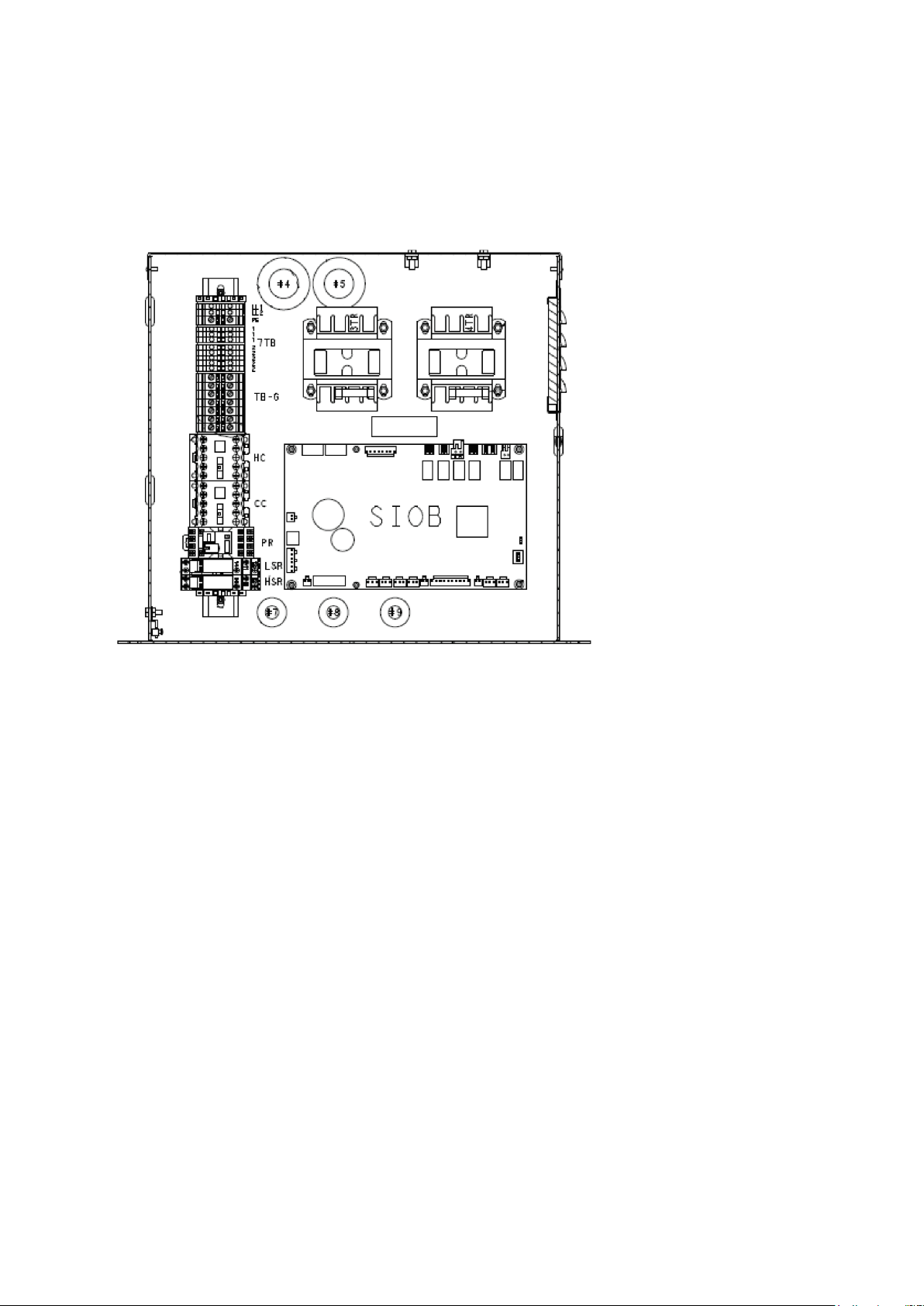
SV01 — Condenser Solenoid Valve
SV02 — Compressor Solenoid Valve
SV03 — Pumpout Solenoid Valve
SV04 — Drain Solenoid Valve
SV05 — Regeneration Solenoid Valve
SV06 — Vent Solenoid Valve
TS01 — Purge Compressor Inlet Temperature
Fig 30 – Purge system wiring
3TR — Transformer
4TR — Transformer
7TB 1,2 — 24VAC Low Voltage Wiring Terminal Block
7TB LL1, LL2 — Main One Phase Power
7TB PE — Ground
CC — Purge Compressor/Fan Contactor
HC — Purge Heater Contactor
HSR — High Level Switch Relay
LSR — Low Level Switch Relay
PR — Purge Vacuum Pump Relay
SIOB — Purge Input/Output Board
Fig 31 – Purge system control box
3.6.3 High pressure safety accessory: SRMCR – Chiller equipped with VFD LF2
3.6.3.1 General description :
The unit is equipped with a safety loop, also called measurement, control and regulation devices playing a role in
safety (SRMCR for protection against overpressure that could be created by the compressor).
Made of :
- 2 active pressure switches (HPS) at compressor discharge
- Safety relay K4 inside the control cabinet
- Power contactor K101 inside the LF2 VFD
- LF2 VFD
See chiller wiring diagram and bill of material (part numbers).
This SRMCR is designed in accordance with EN ISO 13849-1: 2016 according to the following characteristics:
- PL d
- Category 3.
58
Page 59
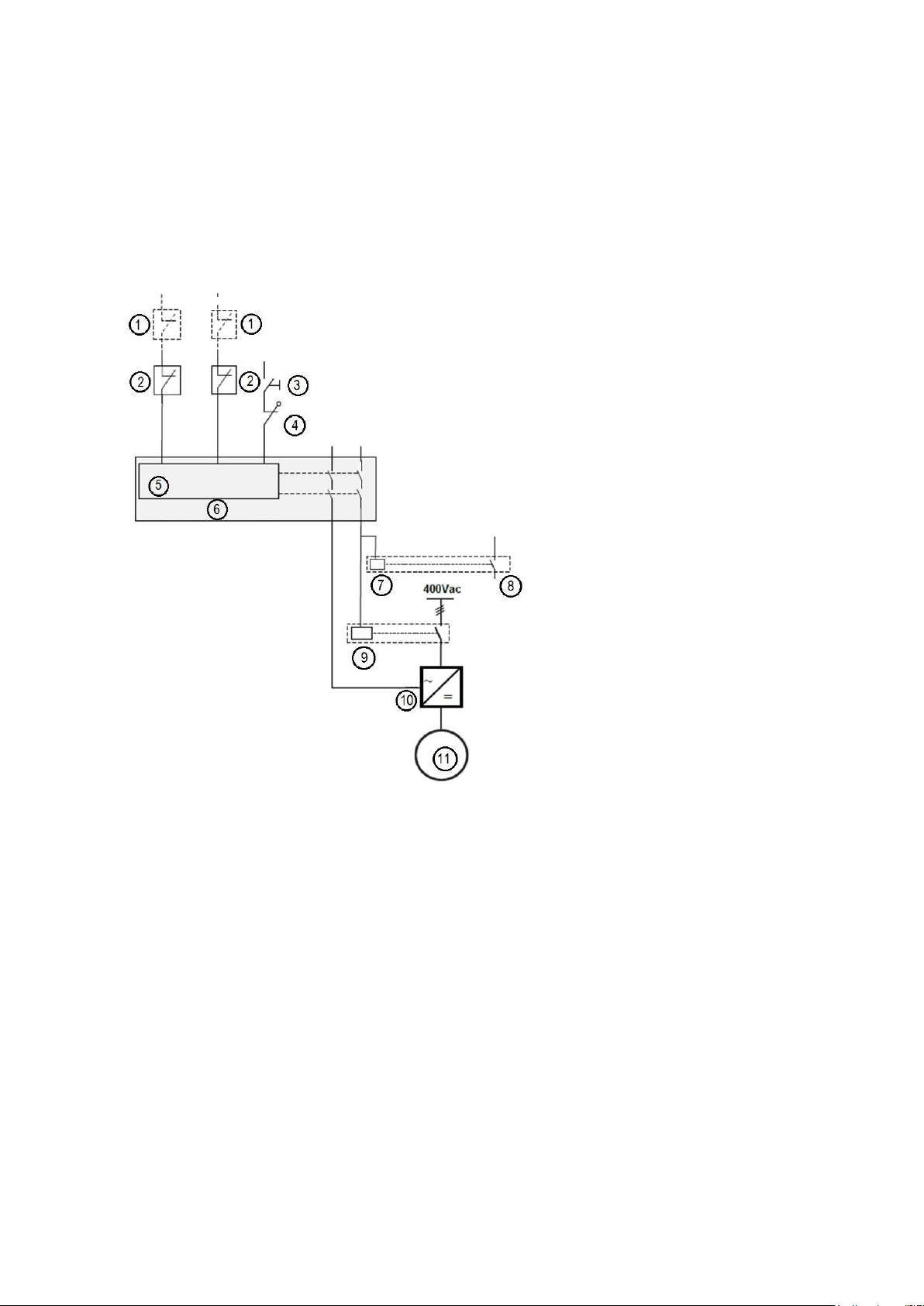
- Mission duration 20 years.
A periodic annual check is required. See annex maintenance test section.
The K4 safety relay monitors the status of the HPS switches as well as the compressor power contactor.
His security contacts are closed under the following conditions :
• No overpressure, closed HPS contacts and no short circuit
• No failure of the power contactor
Activation of one of the two HPS causes the opening of the safety contacts of the K4 relay which causes the
opening of the power contactor and the activation of the gate kill input of the VFD.
The functionality and setting of this safety loop must be checked at least annually, in accordance with the
applicable national regulations. See annex XX for the test procedure.
3.6.3.2 Operation, commissioning and reset
The diagram below is for illustration: refer to the wiring diagram supplied with the machine for detailed information.
1. HPS spare : Non active pressure switch
2. HPS : active pressure switch
3. Reset : button reset
4. K101 : main power contactor
5. Logic
6. Safety relay K4
7. K2 control relay
8. To control (status feedback)
9. K101
10. Gate kill
11. Compressor
Figure 32 – SRMCR description
The K4 safety relay monitors the status of the two active pressure switch (HPS) sensors, the absence of a shortcircuit between the sensors, and the position of the K101 contactor power contacts.
After switching on, the closing of its safety contacts is carried out by pressing the Reset button if the following
conditions are met:
The contacts of the pressure switches are closed (no overpressure)
Contactor K101 is open: its auxiliary NC contact is closed.
The safety contacts open when an HPS sensor is opened.
This causes the opening of the contactor K101 by removing the voltage that supplies its coil. The drive power is off
(K101) and the Gate Kill input of the drive is open; each of his actions being sufficient to stop the compressor.
59
Page 60
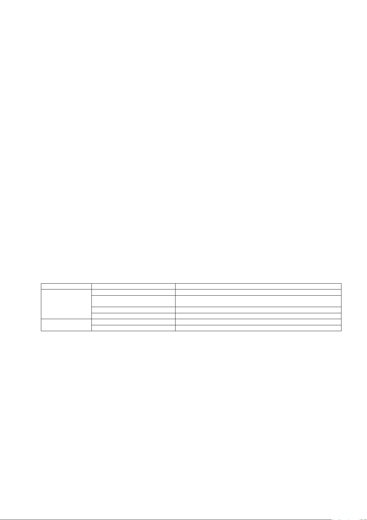
Relay K2 provides feedback to machine control with no effect on the safety function.
LED status
Status
Description
PWR/Fault
Continuous green
Normal operating
Blinking red
Non-resettable fault. Need Cycling of supply voltage
Example: only one pressure switch open.
Green + red blinking
Resettable fault.
Continuous red
Internal fault ; Need Cycling of supply voltage
IN
ON
HPS closed
OFF
HPS opened
The architecture is two-channel:
A first functional channel consisting of the pressure switches sensors, the safety relay and the contactor K101.
A second functional channel consisting of the pressure switch sensors, the safety relay and the LF2 drive, with its
Gate-Kill function.
The reset of the HPS sensors is automatic when the pressure has dropped to an acceptable level. However, the
safety relay is configured for a controlled manual reset: closing its safety contacts always requires an action on the
reset button (see below).
3.6.3.3 Restart after triggering a High pressure switch
If a single pressure switch (HPS) is opened, the safety relay detects an inconsistency between the two sensors
and is de-energized to allow a change of state.
In this case, the restart procedure is as follows:
• Switch off the safety relay.
• Wait 5 seconds
• Switch on the safety relay again
• Wait 5 seconds
• Press the reset button
The duration of pressing the reset button is controlled: it must be between 250ms and 3s.
3.6.3.4 Feedback state of pre-actionning relay contacts
The state of the power contactor is linked to the relay SI 440R by a mirror contact circuit. Relay safety contacts
can only go into the closed position when the state is closed.
This good feedback is checked at each relay initialization and at each activation of the safety loop, annually during
the functional test of the loop.
The proper operation of the Gate Kill function is self-controlled by the drive.
3.6.3.5 Detection of crossed short circuits
The safety relay also has the function of detecting any short-circuit that may occur between the inputs of the safety
pressure switches (HPS).
3.6.3.6 Safety relay LED state
The state of the relay can be visually verified with the status LEDs present on the component:
3.6.4 VFD wiring :
Incoming power is connected to the line side of the circuit breaker inside the VFD.
Connect Wiring to VFD — Connect control wiring to the VFD. All control wiring must use shielded cable. Also,
connect the communications cable. Refer to the job wiring diagrams for cable type and cable number. Make sure
the control circuit is grounded in accordance with applicable electrical codes and instructions on machine control
wiring label.
For Rockwell VFD, UPS can not be connected directly without VFD modification.
NOTE:
I General
1.0 Variable Frequency Drive (VFD) shall be designed and manufactured in accordance with Carrier engineering
requirement.
1.1 All field-supplied conductors and devices must be compliant, and be installed in compliance with all applicable
codes and job specifications.
1.2 The routing of field-installed conduit and conductors and the location of field-installed devices must not
interfere with equipment access or the reading, adjusting or servicing of any component.
60
Page 61
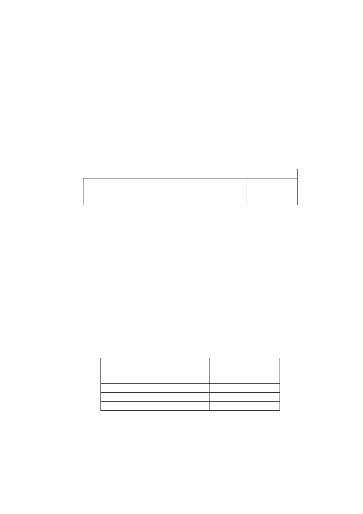
1.3 Equipment installation and all starting and control devices must comply with details in equipment submittal
Maximum connectable wire sections
VFD type
VFD max input amps
Conductors qty
Sections (mm2)
Rockwell 2CC
608
3
95 to 240
Rockwell 4CC
900
4
50 to 300
Signal type
CCN Bus Conductor
Insulation Color
CCN Network
Interface (PIC5+
Touch Screen Panel)
+
Red
+
Ground
White
G
-
Black
-
drawings and literature.
1.4 Contacts and switches are shown in the position they would assume with the circuit deenergized and the
chiller shutdown.
1.5 Warning — Do not use aluminum conductors.
1.6 Warning — Remove panel above VFD main circuit breaker before drilling. Do not drill into any other VFD cabinet panels.
II Power Wiring To VFD
2.0 Provide a means of disconnecting branch feeder power to VFD. Provide short circuit protection and interrupt
capacity for branch feeder in compliance with all applicable codes.
2.1 Metal conduit must be used for the power wires, from VFD to branch feeder.
2.2 Line side power conductor rating must meet VFD nameplate voltage and chiller full load amps (minimum
circuit ampacity).
2.3 Lug adapters may be required if installation conditions dictate that conductors be sized beyond the minimum
ampacity required. Circuit breaker lugs will accommodate the quantity (#) and size cables (per phase) as follows.
If larger lugs are required, they can be purchased from the manufacturer of the circuit breaker (Cutler-Hammer or
Square D).
2.4 Compressor motor and controls must be grounded by using equipment grounding lug provided inside unitmounted VFD enclosure.
IMPORTANT: Before connection of the main power cables (L1 - L2 - L3) on the terminal block, it is imperative to
check the correct order of the 3 phases before proceeding to the connection on then terminal block or the main
disconnect/isolator switch.
3.6.5 Carrier Comfort Network Interface (CCN)
The Carrier Comfort Network (CCN) communication bus wiring is supplied and installed by the electrical
contractor. It consists of shielded, 3-conductor cable with drain wire.
The system elements are connected to the communication bus in a daisy chain arrangement. The positive pin of
each system element communication connector must be wired to the positive pins of the system element on either
side of it. The negative pins must be wired to the negative pins. The signal ground pins must be wired to the signal
ground pins. See Fig. 33 for location of the CCN network connections on the terminal strip labelled CCN.
Conductors and drain wire must be 0.5mm2 minimum stranded, tinned copper. Individual conductors must be
insulated with PVC, PVC/nylon, vinyl, Teflon, or polyethylene. An aluminum/polyester 100% foil shield and an
outer jacket of PVC, PVC/nylon, chrome vinyl, or Teflon with a minimum operating temperature range of -20 °C to
60 °C is required. See table below for cables that meet the requirements.
When connecting the CCN communication bus to a system element, a color code system for the entire network is
recommended to simplify installation and checkout. The following color code is recommended:
If a cable with a different color scheme is selected, a similar color code should be adopted for the entire network.
at each system element, the shields of its communication bus cables must be tied together. If the communication
bus is entirely within one building, the resulting continuous shield must be connected to ground at only one single
point. See Fig. 33. If the communication bus cable exits from one building and enters another, the shields must be
connected to ground at the lightening suppressor in each building where the cable enters or exits the building (one
point only).
To connect the 19DV chiller to the network, proceed as follows (see Fig. 33):
1. Route wire through knockout in back of control panel.
2. Strip back leads.
61
Page 62
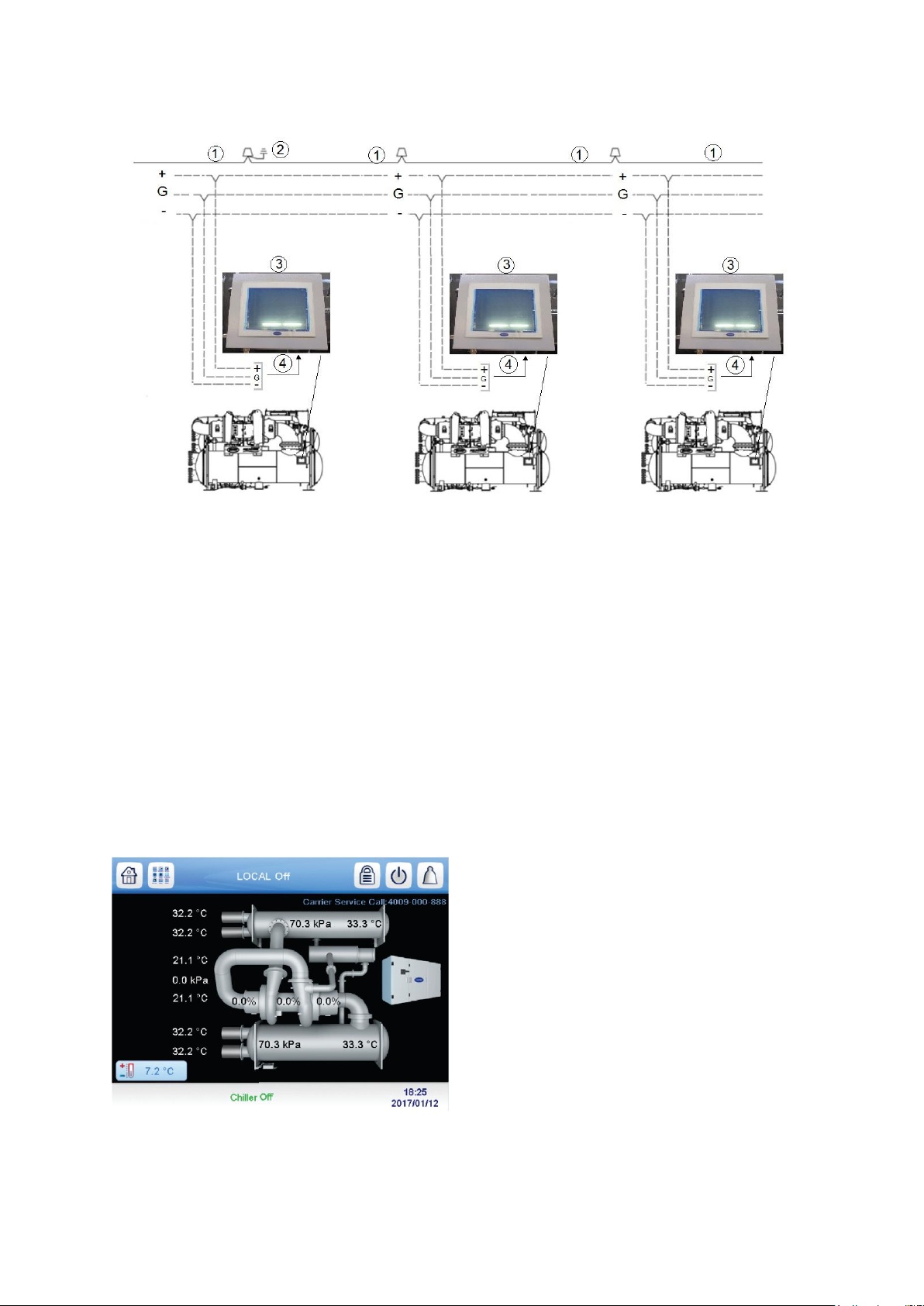
3. Crimp one no. 8 size spring spade terminal on each conductor.
4. Attach red to “+” terminal and white to “G” terminal and black to “–” terminal of CCN Network interface
located in the PIC5+ touch screen panel.
1: drain wire
2 : ground drain wire
3 : PIC5+ touch screen panel
4 : CCN wiring
______ : factory wiring
- - - - - - : field wiring
Fig 33 – CCN network wiring
4 START-UP/SHUT-DOWN/RECYCLE SEQUENCE
4.1 Local Start/Stop Control
Local start-up (or manual start-up) is initiated by pressing the gray Start/Stop icon on the HMI interface. See fig 34
Fig 34 – Chiller start/stop icon
This initiates the PIC5+ starting sequence by displaying the list of operating modes. Press Local On to initiate
start-up. See Fig. 35.
62
Page 63
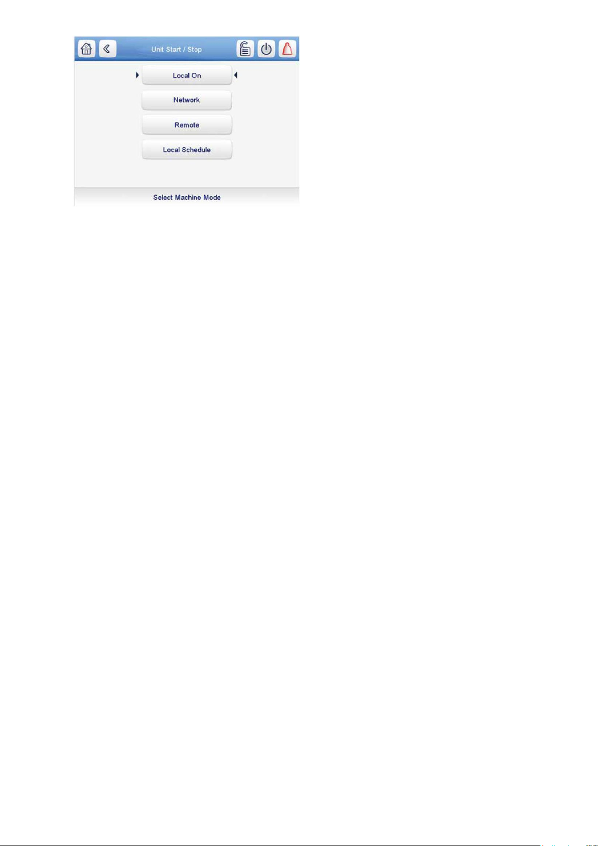
Fig 35 – Operating mode / Local On
Note: Prior to start-up, the start-to-start timer and the stop-to-start timer must have elapsed and all alarms must be
cleared.
When start-up is initiated, the status screen displays the startup progress and the Start/Stop icon blinks green.
Once local start-up begins, the PIC5+ control system performs a series of prestart tests to verify that all prestart
alerts and safeties are within acceptable limits. Table XX shows appropriate Prestart Alerts/Alarms conditions. If a
test is not successful, the start-up is delayed or aborted. If the tests are successful, the start-up will be in progress
and the COMPRESSOR RUN STATUS shall be “Startup.” The control shall then energize the chilled water/brine
pump relay.
Five seconds later, the condenser pump relay energizes. Thirty seconds later the PIC5+ control system monitors
the chilled water and condenser water flow devices and waits until the WATER FLOW VERIFY TIME (operatorconfigured, default 5 minutes) expires to confirm flow.
After flow is verified, the chilled water temperature is compared to CONTROL POINT plus 1/2 CHILLED WATER
DEADBAND. If the temperature is less than or equal to this value, the PIC5+ control system turns off the
condenser pump relay and goes into a Recycle mode.
If the water/brine temperature is high enough, the start-up sequence continues and checks the guide vane
position. If the guide vanes are more than 4% open, the start-up waits until the PIC5+ control system closes the
vanes. If the vanes are closed and the refrigerant pump pressure difference is less than 34.5 kPa, the refrigerant
pump relay energizes.
The PIC5+ control system then waits until the refrigerant pressure (REF PRESS VERIFY TIME, operatorconfigured, default of 40 seconds) reaches a maximum of 82.7 kPa. After refrigerant pressure is verified, if high
side float chamber has adequate liquid level, refrigerant pump will be kept ON for 20 seconds for pre-lube; if not,
refrigerant pump will be kept ON pumping refrigerant from evaporator to the high side float chamber until liquid
level is satisfied. Upon pre-lube satisfied the compressor start relay is energized.
Compressor on-time and service on-time timers start, and the compressor STARTS IN 12 HOURS counter and
the number of starts over a 12-hour period counter advance by one.
Failure to verify any of the requirements up to this point will result in the PIC5+ control system aborting the start
and displaying the applicable prestart alert alarm state number near the bottom of the home screen on the HMI
panel. A prestart failure does not advance the STARTS IN 12 HOURS counter. Any failure after the compressor
relay has energized results in a safety shutdown, advances the starts in 12 hours counter by one, and displays the
applicable shutdown status on the display.
The minimum time to complete the entire prestart sequence is approximately 185 seconds. See Fig. 36 for normal
start-up timing sequence. See Table 15 for a list of prestart checks.
63
Page 64
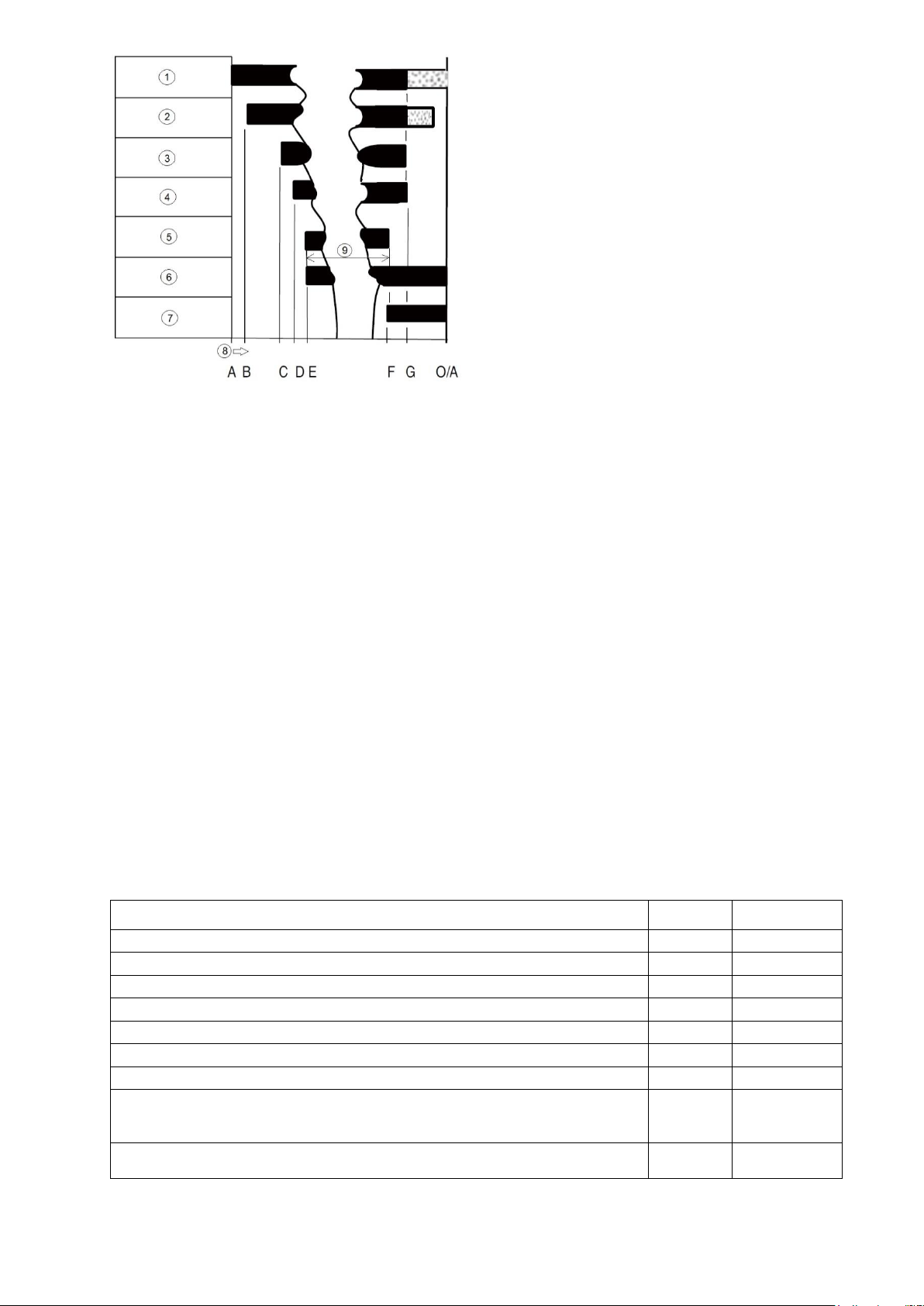
1 : Machine safeties evaporator pump
Prestart check / alert - alarm condition *
State
Number
Alarm or Alert
STARTS IN 12 HOURS >= 8 (not counting recycle restarts or auto restarts after power failure)
100
Alert
CONDENSER PRESSURE >= COND PRESS OVERRIDE /186.2kPa
102
Alert
Number of recycle restart in the last 4 hours is greater than 5
103
Alert
COMP BEARING TEMP >= COMP BEARING ALERT/ 5.6°C
230
Alarm
COMP MOTOR WINDING TEMP >= MOTOR TEMP OVERRIDE / 5.6°C
231
Alarm
COMP DISCHARGE TEMP >= COMP DISCHARGE ALERT/ 5.6°C
232
Alarm
EVAP_SAT < Evap. trip point** + EVAP OVERRIDE DELTA T OR
EVAP REFRIG LIQUID TEMP < Evap. trip point + EVAP OVERRIDE DELTA T
NOTE: Evap. trip point = 0.56°C(water) or EVAP REFRIG TRIPPOINT(brine)
233
Alarm
ACTUAL LINE VOLTAGE <= UNDERVOLTAGE THRESHOLD
(Not applicable for Rockwell UM VFDs)
234
Alarm
2 : Condenser water pump
3 : Waterflow chilled water temp, guide vanes, refrigerant pump, and tower fan control
4 : Refrigerant pump
5 : Compressor, compressor on time, service on time
6 : 15-minute start-to-start
7 : 2 minute stop-to-start
8 : Elapsed time
9 : Compressor running
A : START INITIATED: Pre-start checks are made; cooler pump started.*
B : Condenser water pump started (5 seconds after A).
C : Water flows verified (30 seconds to 5 minutes maximum af-ter B). Chilled water temperatures checked against
control point. Guide vanes checked for closure. Refrigerant pump started; tower fan control enabled.
D : Ref pressure verified (15 seconds minimum, 300 seconds maximum after C).
E : Compressor motor starts; compressor ontime and service ontime start, 15-minute inhibit timer starts
(20seconds after D), total compressor starts advances by one, and the num-ber of starts over a 12-hour period
advances by one.
F : SHUTDOWN INITIATED — Compressor motor stops; compressor ontimeand service ontime stop, and 2minute inhibit timer starts.
G : Ref pump and cooler pumps de-energized (120 seconds after F).Condenser pump and tower fan control may
contin-ue to operate if condenser pressure is high. Cooler pump may continue if in RECYCLE mode.
O/A : Restart permitted (both inhibit timers expired: minimum of 15 minutes after E; minimum of 2 minute after F).
* : Autorestart after power failure timing sequence will be faster.
Fig 36 – Control Timing Sequence for Normal Start-Up
64
Page 65

ACTUAL LINE VOLTAGE >= OVERVOLTAGE THRESHOLD
(Not applicable for Rockwell UM VFDs)
235
Alarm
Guide vane 1 has not been calibrated successfully
236
Alarm
Guide vane 2 has not been calibrated successfully
238
Alarm
* : If prestart Check condition is true, then resulting state is as indicated in the state number column.
Table 15 – Prestart check / alert – alarm conditions
The compressor RUN STATUS parameter on the default screen line now reads PRESTART. If one test is not
successful, the start-up is delayed or aborted. If all the tests are successful, the chilled water pump relay
energizes, and the main screen line now reads STARTUP.
4.2 Lubrication control
For the 19DV system, refrigerant is used to lubricate and cool the compressor bearings. The refrigerant lubrication
system includes refrigerant pump, pressure transducers, control valves, filters, liquid level switch See Fig. 37 for
the lube assembly schematic.
When the chiller is powered on, the controller will maintain liquid level in condenser float chamber. If liquid level is
low, refrigerant will be pumped from cooler to condenser high side float chamber until the liquid level switch is ON.
Once the operator pushes the start button, the system will go into prestart check process.
When Refrigerant Pump request is on for pre-lube and the bearing pressure difference is OK for start, if cooler
temperature minus leaving condenser water temperature is less than 5.6°C, pump refrigerant from Cooler to
Condenser until compressor is ON. Else, if cooler temperature plus leaving condenser water is equal or larger
than 5.6°C, pump refrigerant from condenser to bearing and drain to condenser until compressor is ON.
During pre-lubrication, if the bearing pressure difference is less than 55.2 kPa for 8 seconds continuously, the
chiller will shut down. To proceed to start-up, the bearing pressure difference needs to exceed 82.7 kPa during the
pressure verification time. The compressor will run after the pre-lubrication process. Refrigerant from the high side
condenser float chamber will be pumped to bearings and will drain to cooler. When chiller shuts down, the
condenser control valve will be opened and the refrigerant evaporator control valve will open (3-way valve will
connect evaporator to pump suction).
This position allows refrigerant to be pumped from cooler to condenser high side float chamber. When the chiller is
OFF, always open cooler control valve. During running, if compressor
is ON and the bearing pressure difference is less 68.9 kPa for 10 seconds continuously, the chiller will shut
down.
65
Page 66
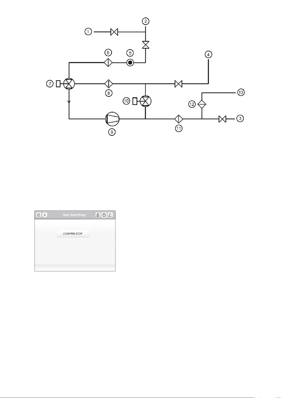
1: purge drain, 2: Cooler, 3: Pumpout drain, 4: High side float chamber, 5: sight glass, 6: strainer, 7: 3-way
actuated valve, 8: strainer, 9: pump, 10: 2-way actuated valve, 11: refrigerant filter, 12: bearing filter, 13: pumpout
drain.
Fig 37 – Lube control assembly schematic
4.3 Shutdown
The unit can be stopped locally using the HMI by pressing the green Start/Stop icon. The Unit Start/Stop screen is
displayed. Press Confirm Stop (see Fig. 38).
Fig. 38 — Confirm Stop
Chiller shutdown begins if any of the following occurs:
• Local OFF button is pressed
• A recycle condition is present
• The time schedule has gone into unoccupied mode when in Network or Local Schedule control mode
• The chiller protective limit has been reached and chiller is in alarm
• The start/stop status (CHIL_S_S) is overridden to stop from the network when in Network mode.
If the chiller is normally shut down from running; soft stop shutdown will be performed. The soft stop feature closes
the guide vanes of the compressor automatically if a non-alarm stop signal occurs before the compressor motor is
de-energized.
Any time the compressor is directed to stop (except in the cases of a fault shutdown), the guide vanes are directed
to close and VFD is directed to minimum speed for variable speed compressor, and the compressor shuts off
when any of the following is true:
• PERCENT LOAD CURRENT (%) drops below the SOFT STOP AMPS THRESHOLD
• ACTUAL GUIDE VANE OPENING drops below 4%
66
Page 67

• 4 minutes have elapsed after initializing stop.
When any one of the above conditions is true, the shutdown sequence stops the compressor by deactivating the
compressor start relay. Then the guide vane shall be closed and stay at the fully closed position, the refrigerant
pump relay will be turned off after 120 seconds post lube, and the chilled water/brine pump and condenser water
pump will be shut down.
5. BEFORE INITIAL START-UP
5.1 - Necessary checks
5.1.1 - Job data required
Checks before system start-up: Before the start-up of the refrigeration system, the complete installation, including
the refrigeration system must be verified against the installation drawings, dimensional drawings, system piping
and instrumentation diagrams and the wiring diagrams.
During the installation test national regulations must be followed. If no national regulation exists, paragraph 9-5 of
standard EN 378-2 can be used as a guide.
External visual installation checks:
• Compare the complete installation with the refrigeration system and power circuit diagrams.
• Check that all components comply with the design specifications.
• Check that all safety documents and equipments required by the applicable European standard are present.
• Verify that all safety and environmental protection devices and arrangements are in place and comply with
the applicable European standard.
• Verify that all documents for pressure containers, certificates, name plates, files, instruction manuals required by
the applicable European standard are present.
• Verify the free passage of access and safety routes.
• Check that ventilation in the plant room is adequate.
• Check that refrigerant detectors are present.
• Verify that the instructions and directives to prevent the deliberate removal of refrigerant gases that are harmful
to the environment are being applied.
• Verify the installation of connections.
• Verify the supports and fixing elements (materials, routing and connection).
• Verify the quality of welds and other joints.
• Check the mechanical integrity of the machine.
• Check the protection against heat.
• Check the protection of moving parts.
• Verify the accessibility for maintenance or repair and to check the piping.
• Verify the status of the valves.
• Verify the quality of the thermal insulation and of the vapour barriers.
5.1.2 - Equipment required
• mechanic’s tools (refrigeration)
• digital volt-ohmmeter (DVM)
• true RMS (root mean square) digital multimeter with clamp-on current probe or true RMS digital clamp-on
ammeter rated for at least 480 vac
• electronic leak detector absolute pressure manometer or electronic micron gage (see Fig. 39)
• drum charging valve (unless refrigerant bottles already have charging valves)
• charging hose
• Refrigerant charge device
67
Page 68
BOLT
SIZE
CLASS 8.8, SAE 5, SA499(N•m)
CLASS10.9, SAE 8, SA354 GR
BD(N•m)
SOCKET HEAD OR HEX
WITH 3 RADIAL LINES
MEDIUM CARBON STEEL
HEX HEAD
WITH 6 RADIAL LINES
MEDIUM CARBON STEEL
mm
Minimum
Maximum
Set
Minimum
Maximum
Set 6 8.1
12.2
10±1
12.2
17.6
14±1 8 17.6
24.4
20±1
27.1
38
34±1
10
29.8
42
34±1
43.4
62.3
47±1
7/16’’
47.4
67.8
61±7
71.8
101.6
81±7
12
71.8
101.6
81±7
108.4
155.8
122±7
14
101.6
149.1
122±14
155.8
223.6
176±14
16
142.3
203.3
163±14
216.8
304.9
244±14
18,
20
237.1
388.8
285±34
352.3
501.4
393±34
22
359.1
514.9
407±34
562.3
799.5
610±34
24
555.6
785.9
597±34
846.9
1210
894±34
27
738.5
1056.9
786±34
1334.7
1910.6
1382±34
30
1043.4
1490.5
1084±34
1870
2655.8
1911±34
Fig 39 : Digital Vacuum gage
5.1.3 - Remove shipping packaging
After receipt remove any packaging material from the unit, VFD, and control panels.
5.1.4 – Lubrication and purge circuit valves
Check if the motorized valves on lubrication circuit are open and all solenoid valves and service valves are open
on purging circuit.
5.1.5 - Tighten all gasketed joints
Gaskets normally relax by the time the chiller arrives at the jobsite. Tighten all gasketed joints to ensure a leaktight chiller (does not apply to refrigerant joints covered by factory insulation). Gasketed joints (excluding O-rings)
may include joints at some or all of the following:
• Waterbox covers
• Compressor first suction elbow flanges (at compressor and at the cooler)
• Compressor secondary suction flanges (at compressor and low side float chamber)
• Compressor discharge flange
• Cooler inlet line spacer (both sides)
• Envelope control flange (both sides of valve)
• ICP piping flange
• High and low side float chamber covers
See Tables 16 for bolt torque requirements.
68
Page 69

33,
36
1382.1
1978.3
1423±34
2493.2
3563.7
2534±34
39
1653.1
2371.3
1721±68
2981
4268.3
3049±68
42
2262.9
3238.5
2331±68
4092.1
5840.1
4160±68
45
2953.9
4214.1
3022±68
5325.2
7601.6
5393±68
48
3970.2
5677.5
4038±68
7154.4
10230.3
7222±68
52
4268.3
6165.3
4336±68
7682.9
10975.5
7751±68
56,
60
6165.3
8807.5
6233±68
11111
15867.1
11179±68
64
6775
96747
6843±68
15379.3
21964.6
15447±68
68
11463.3
16382
11531±68
221287.1
30406.2
21355±68
72,
76
14959.2
21368.4
15027±68
26964.5
38536.2
27032±68
Table 16 : Bolt torque requirements N.m (gasket or O-ring joint)
5.1.6 Check Chiller Tightness
Chillers can be shipped either with full refrigerant charge or with 1 bar dry nitrogen-holding charge.
5.1.6.1 Chiller shipped with 1 bar nitrogen-holding charge / without refrigerant:
Follow chart figure 40 – 19DV leak test procedure
To check leaks in chiller, in addition to the nitrogen gas, the chiller should be charged with helium tracer gas. Use
an electronic leak detector to check all flanges and solder joints after the chiller is pressurized. If any leak is
detected, follow the leak test procedure.
If the chiller is spring isolated, keep all springs blocked in both directions to prevent possible pipe stress and
damage during the transfer of refrigerant from vessel to vessel during the leak test process, or any other time
refrigerant is transferred. Before initial start, ensure that springs are adjusted, chiller is charged with refrigerant,
and water circuits are full with water.
69
Page 70
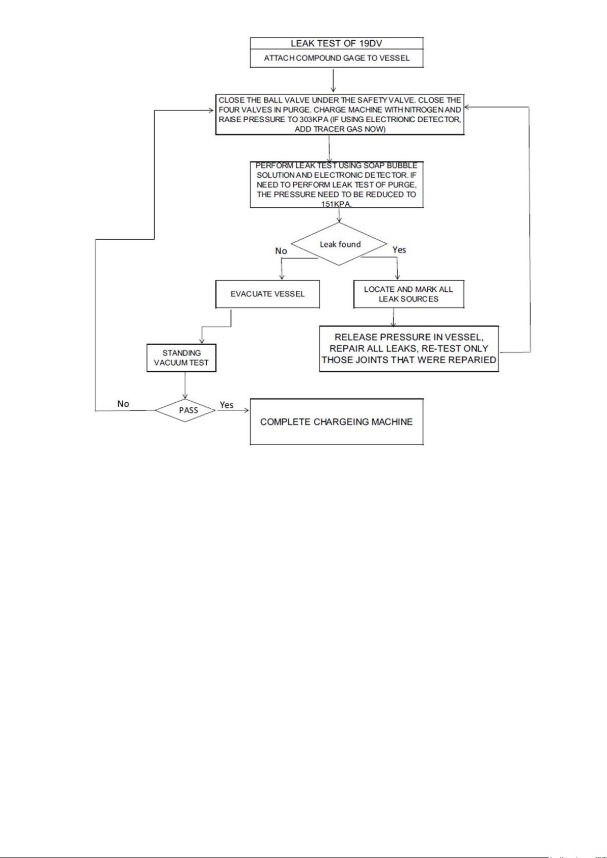
Fig 40 – 19DV leak test procedure
5.1.6.2 Refrigerant Tracer
Carrier recommends the use of an environmentally acceptable refrigerant tracer for leak testing with an electronic
detector. Ultrasonic leak detectors can also be used if the chiller is under pressure.
WARNING: Do not use air or oxygen as a means of pressurizing the chiller. Mixtures of HFO R-1233zd(E) and air
at elevated pressure can undergo combustion, resulting in equipment damage and possible personal injury.
5.1.6.3 Leak Test Chiller
Due to regulations regarding refrigerant emissions and the difficulties associated with separating contaminants
from the refrigerant, Carrier recommends the following leak test procedure. Refer to Table XX for refrigerant
pressure/temperature values.
1. If the pressure readings are normal for the chiller condition:
a. Evacuate the charge from the vessels, if present.
b. Raise the chiller pressure, if necessary, by adding refrigerant until pressure is at the equivalent saturated
pressure for the surrounding temperature.
CAUTION: Never charge liquid refrigerant into the chiller if the pressure in the chiller is less than R-1233zd(E)
saturation pressure corresponding to local temperature. Charge as a gas only, with the cooler and condenser pumps
running, until this pressure is reached, using PUMPDOWN/LOCKOUT (located in the Maintenance menu) and
END LOCKOUT mode on the PIC5+ control interface. Flashing of liquid refrigerant at low pressures can cause
tube freeze-up and considerable damage.
70
Page 71
Temperature / °C
Pressure / kPag
Pressure / kPa
abs
% vaccum
-12.2
-74.1
27.3
75
-9.4
-70.1
31.3
70
-6.7
-65.8
35.6
65
-3.9
-60.9
40.5
60
-1.1
-55.5
45.9
55
1.7
-49.6
51.8
49
4.4
-43
58.4
42
7.2
-35.8
65.6
36
10
-28
73.4
28
12.8
-19.3
82.1
19
15.6
-10
91.4
10
18.3
0.3
101.7
-
21.1
11.4
112.8
-
23.9
23.4
124.8
-
26.7
36.4
137.8
-
c. Leak test chiller as outlined in Steps 3 to 9.
2. If the pressure readings are abnormal for the chiller condition:
a. Prepare to leak test chiller.
b. For cooling machines, check for leaks by connecting a nitrogen bottle with added tracer to allow for
electronic leak detection if possible; otherwise, soap bubble solution is to be used. Raise the pressure to a. If
electronic leak detector is available, ensure small amount of tracer material is added.
c. Plainly mark any leaks that are found.
d. Release the pressure in the system.
e. Repair all leaks.
f. Retest the joints that were repaired (note suggested test pressure is 138 kPa; maximum allowable
test pressure 310 kPa.
3. Check the chiller carefully with an electronic leak detector or soap bubble solution.
4. Leak Determination
If an electronic leak detector indicates a leak, use a soap bubble solution, if possible, to confirm. Total all leak
rates for the entire chiller. Leakage at rates greater than 0.1% of the total charge per year should be repaired.
Local regulation governs the requirements for when repair of leaks become mandatory. Note
the total chiller leak rate as well as the full charge amount on the start-up report.
5. If no leak is found during the initial start-up procedures, complete the transfer of refrigerant gas from the
storage tank to the chiller. Recover any gas used for leak detection purposes as required per local jurisdiction.
6. If no leak is found after a retest:
a. Perform a standing vacuum test as outlined in the Standing Vacuum Test section, below.
b. b. If the chiller fails the standing vacuum test, repeat leak test and repair.
c. If the chiller passes the standing vacuum test, dehydrate the chiller. Follow the procedure in the
Chiller Dehydration. Charge the chiller with refrigerant.
7. If the chiller is opened to the atmosphere for an extended period, evacuate it before repeating the leak test.
NOTE: Alternate optional leak testing method is to isolate the water circuits and use a portable water heater to
raise the temperature of the cooler and condenser water circuits to approximately 38°C which corresponds to a
pressure of 99.3 kPag.
71
Page 72

29.4
50.5
151.9
-
32.2
65.6
167
-
35
81.9
183.3
-
37.8
99.3
200.7
-
40.6
118.1
219.5
-
43.3
138.1
239.5
-
46.1
159.6
261
-
48.9
182.4
283.8
-
51.7
206.8
308.2
-
54.4
232.7
334.1
-
57.2
260.3
361.7
-
60
289.6
391
-
Table 17 – R1233zd(E) Pressure / Temperature
5.1.7 Standing Vacuum Test
When performing the standing vacuum test or chiller dehydration, use a manometer or a wet bulb indicator. Dial
gages cannot indicate the small amount of acceptable leakage during a short period of time.
1. Attach an absolute pressure manometer or wet bulb indicator to the chiller.
2. Evacuate the vessel to at least 0.06 kPa [abs], using a vacuum pump.
3. Shut off pump valve to hold the vacuum and record the manometer or wet bulb indicator reading.
4. If the pressure rise is less than 56 Pa within 8 hours, the chiller is sufficiently tight.
If the pressure rise exceeds above criteria, re-pressurize the vessel and conduct leak test and repair the leak
point.
5.1.8- Chiller dehydration
Dehydration is recommended if the chiller has been open for a considerable period of time, if the chiller is known
to contain moisture, or if there has been a complete loss of chiller holding charge or refrigerant pressure.
CAUTION: Do not start or megohm-test the compressor motor or any other pump motor, even for a rotation check,
if the chiller is under dehydration vacuum. Insulation breakdown and severe damage may result.
WARNING: Power to the motor and VFD must be disconnected by an isolation switch before placing the machine
under a vacuum. To be safe, isolate input power before evacuating the chiller if you are not sure if there are live
leads to the hermetic motor.
Dehydration can be done at room temperatures. Using a cold trap (Fig. 41) may substantially reduce the time
required to complete the dehydration and is recommended should the unit be exposed to liquid moisture. The
higher the room temperature, the faster dehydration takes place. At low room temperatures, a very deep vacuum
is required for boiling off any moisture. If the ambient temperatures are low, contact a qualified service
representative for the dehydration techniques required.
72
Page 73
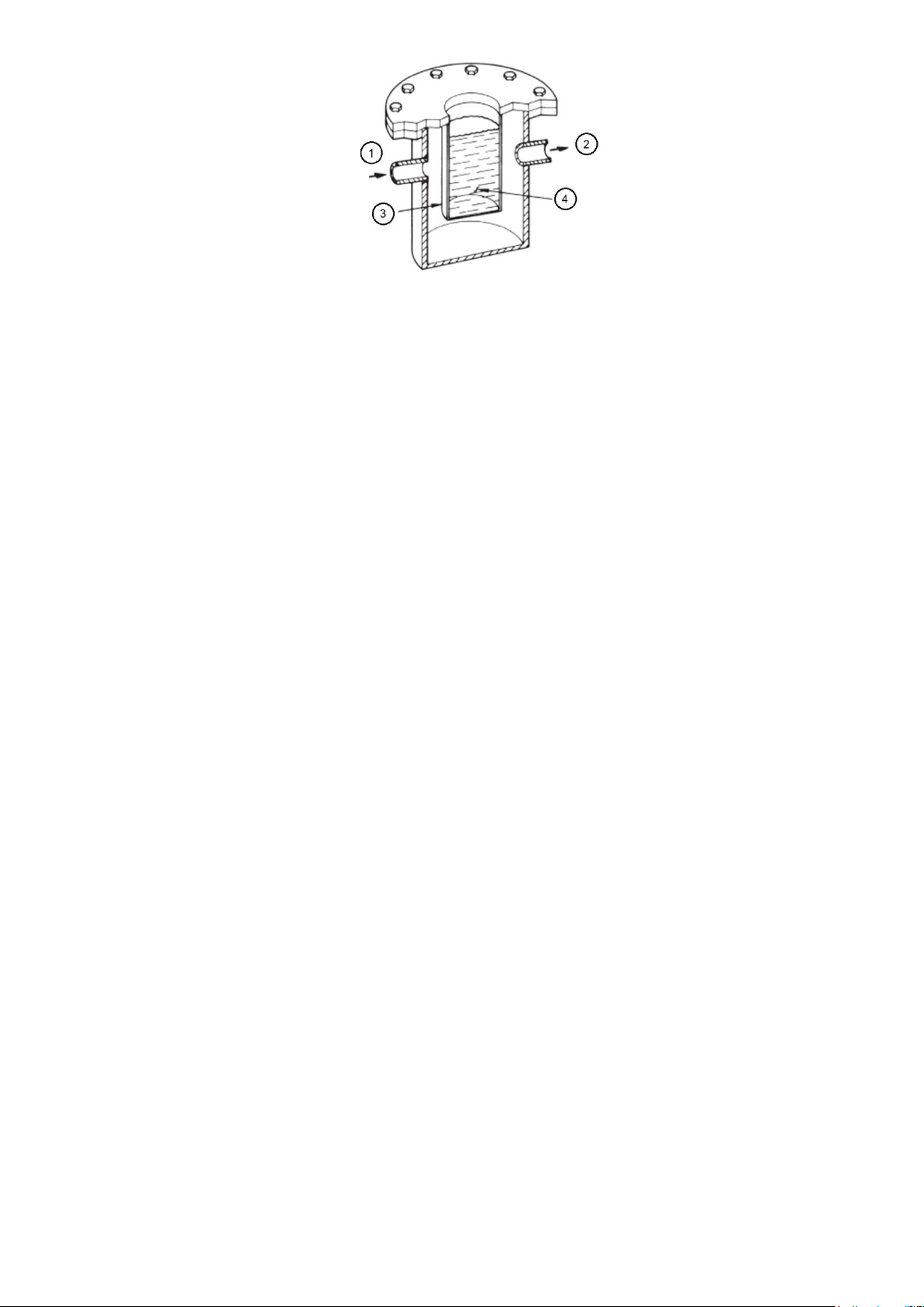
1: From system
2: To vacuum pump
3: Moisture condenses on cold surfaces
4: Mixture of dry ice and methyl alcohol
Fig 41 – dehydration cold trap
Perform dehydration as follows:
1. Connect a high capacity vacuum pump (0.002 m3/s or larger is recommended) to the refrigerant vacuum/
charging valve. Tubing from the pump to the chiller should be as short in length with a minimum diameter of 13
mm and as large in diameter as possible to provide least resistance to gas flow.
2. Use an absolute pressure manometer or a electronic micron gage to measure the vacuum. Open the shutoff
valve to the vacuum indicator only when taking a reading. Leave the valve open for 3 minutes to allow the
indicator vacuum to equalize with the chiller vacuum.
3. If the entire chiller is to be dehydrated, open all isolation valves (if present).
4. With the chiller ambient temperature at 15.6°C or higher, operate the vacuum pump until the manometer reads
757 mm Hg (vac), (-100.9 kPag), or a vacuum indicator reads 1.7°C. Operate the pump an additional 2 hours. Do
not apply a greater vacuum than 100.1 kPa (757 mm Hg) or go below 0.56°C on the wet bulb vacuum indicator.
At this temperature and pressure, isolated pockets of moisture can turn into ice. The slow rate of evaporation
(sublimation) of ice at these low temperatures and pressures greatly increases dehydration time.
5. Valve off the vacuum pump, stop the pump, and record the instrument reading.
6. After a 2-hour wait, take another instrument reading. If the reading has not changed, dehydration is complete. If
the reading indicates vacuum loss, repeat Steps 4 and 5.
7. If the reading continues to change after several attempts, perform a leak test (maximum 310 kPa pressure).
Locate and repair the leak, and repeat dehydration.
8. Once dehydration is complete, the evacuation process can continue. The final vacuum prior to charging the unit
with refrigerant should in all cases be 0.3 kPa [abs] or less.
5.1.9- Inspect water piping
Refer to piping diagrams provided in the certified drawings, Inspect the piping to the cooler and condenser. Be
sure that flow directions are correct and that all piping specifications have been met. Check the tightening of
waterboxes mounting. Check if there’s no water leak between tube-sheet and waterbox. Do not introduce any
significant static or dynamic pressure into the heat exchange circuit (with regard to the design operating
pressures).
Before any start-up verify that the heat exchange fluid is compatible with the materials and the water circuit
coating. In case additives or other fluids than those recommended by Carrier are used, ensure that the fluids are
not considered as a gas, and that they belong to class 2, as defined in directive 97/23/EC.
Carrier recommendations on heat exchange fluids:
• No NH4+ ammonium ions in the water, they are very detrimental for copper. This is one of the most important
factors for the operating life of copper piping. A content of several tenths of mg/l will badly corrode the copper over
time.
• Cl- Chloride ions are detrimental for copper with a risk of perforations by corrosion by puncture. If possible
keep below 10 mg/l.
• SO4 2- sulphate ions can cause perforating corrosion, if their content is above 30 mg/l.
No fluoride ions (<0.1 mg/l).
• No Fe2+ and Fe3+ ions with non negligible levels of dissolved oxygen must be present. Dissolved iron < 5 mg/l
with dissolved oxygen < 5 mg/l.
• Dissolved silica: Silica is an acid element of water and can also lead to corrosion risks. Content < 1mg/l.
73
Page 74

• Water hardness: >0.5 mmol/l. Values between 1 and 2.5 mmol/l can be recommended. This will facilitate scale
deposit that can limit corrosion of copper. Values that are too high can cause piping blockage over time. A
carbonate hardness (TAC) below 100 is desirable.
• Dissolved oxygen: Any sudden change in water oxygenation conditions must be avoided. It is as detrimental to
deoxygenate the water by mixing it with inert gas as it is to over-oxygenate it by mixing it with pure oxygen. The
disturbance of the oxygenation conditions encourages destabilisation of copper hydroxides and enlargement of
particles.
• Specific resistance - electric conductivity: The higher the specific resistance, the slower the corrosion tendency.
Values above 30 Ohm·m are desirable. A neutral environment favours maximum specific resistance values. For
electric conductivity values in the order of 20-60 mS/m can be recommended.
• pH: Ideal case pH neutral at 20-25 °C 7 < pH < 8
If the water circuit must be emptied for longer than one month, the complete circuit must be placed under nitrogen
charge to avoid any risk of corrosion by differential aeration. Charging and removing heat exchange fluids should
be done with devices that must be included on the water circuit by the installer. Never use the unit heat
exchangers to add heat exchange fluid.
Piping systems must be properly vented, with no stress on waterbox pipes and covers. Use flexible connections to
reduce the transmission of vibrations. Water flows through the cooler and condenser must meet job requirements.
Measure the pressure drop across cooler and across condenser and compare this with the nominal values (see
selection document).
CAUTION: Water must be within design limits, clean, and treated to ensure proper chiller performance and to
reduce the potential of tube damage due to corrosion, scaling, or erosion. Carrier assumes no responsibility for
chiller damage resulting from untreated or improperly treated water.
5.1.10 - Check relief devices
Be sure that relief devices have been piped to the outdoors in compliance with standard EN 378-2. Piping
connections must allow for access to the valve mechanism for periodic inspection and leak testing. The standard
19DV relief valves are set to relieve at 500 kPa pressure.
5.2 Inspect wiring
WARNING: Do not check the voltage supply without proper equipment and precautions. Serious injury may result.
Follow power company recommendations.
CAUTION: Do not apply any kind of test voltage, even for a rotation check, if the chiller is under a dehydration
vacuum. Insulation breakdown and serious damage may result.
1. Examine the wiring for conformance to the job wiring diagrams and all applicable electrical codes.
2. Connect a voltmeter across the power wires to the VFD and measure the phase to phase and phase to
ground voltage. The voltage imbalance for these two measurements should be consistent. If not, confirm
the power supply to the chiller is a wye configuration with solidly grounded neutral. Compare this reading
to the voltage rating on the compressor and VFD nameplates.
3. Compare the ampere rating on the VFD enclosure nameplate to the rating on the compressor nameplate.
4. The VFD must be wired to components and terminals required for PIC5+ refrigeration control. Check line
side power and control components shown on the certified prints.
5. Ensure that fused disconnects or circuit breakers have been supplied to the VFD.
6. Ensure all electrical equipment and controls are properly grounded in accordance with the job drawings,
certified drawings, and all applicable electrical codes.
7. Ensure the customer’s contractor has verified proper operation of the pumps, cooling tower fans, and
associated auxiliary equipment. This includes ensuring motors are properly lubricated and have proper
electrical supply and proper rotation. The 19DV unit must maintain pump control through the IOBs/Carrier
Control Panel for freeze prevention algorithm.
8. Verify tightness of all wiring connections on the high and low voltage terminal blocks in the VFD
enclosure.
9. Inspect the control panels and VFD enclosure to ensure that the contractor has used the knockouts or
provided top hat to feed the wires into the enclosures. Generally, wiring into the top of the enclosures can
allow debris to fall into the enclosures. Clean and inspect the interior of the power panel and VFD
74
Page 75

enclosure if this has occurred. If metal particulate has fallen into the rectifier or inverter assemblies
contact Service Engineering or your Technical Service Manager for further instructions.
WARNING: Do not apply power unless a qualified Carrier technician is present. Serious personal injury may result.
5.3 Ground Fault Troubleshooting
Follow this procedure only if ground faults are declared by the chiller controls. Test the chiller compressor motor
and its power lead insulation resistance with a 500-v insulation tester such as a megohmmeter.
1. Open the VFD main disconnect switch and follow lockout/ tagout rules.
CAUTION: The motor leads must be disconnected from the VFD before an insulation test is performed. The voltage
generated from the tester can damage the VFD.
2. With the tester connected to the motor leads, take 10-second and 60-second megohm readings as follows: Tie
terminals 1, 2, and 3 together and test between the group and ground.
3. Divide the 60-second resistance reading by the 10-second reading. The ratio, or polarization index, must be one
or higher. Both the 10 and 60-second readings must be at least 50 megohms.
If the readings are unsatisfactory, repeat the test at the motor with the power leads disconnected. Satisfactory
readings in this second test indicate the fault is in the power leads.
5.4 Check Purge Compressor Operation
Enter Quick Test menu (under Main Menu), select “Quick Test Purge Comp.” Connect a pressure gauge to purge
compressor inlet Schrader valve (suction is top fitting). The purge system is shown in Fig. 10. The reading should
be about 62.1+/- 6.9 kPa. If not, please adjust the purge expansion valve in the R-134a purge compressor circuit
until the reading is correct.
NOTE: This step should only be performed if the purge is not working correctly. The installation of the gage will
result in a loss of refrigerant and the charge of R-134a is a very small quantity affecting the operation of the purge.
The charge should be weighed into this circuit using a charging cylinder or similar device.
75
Page 76
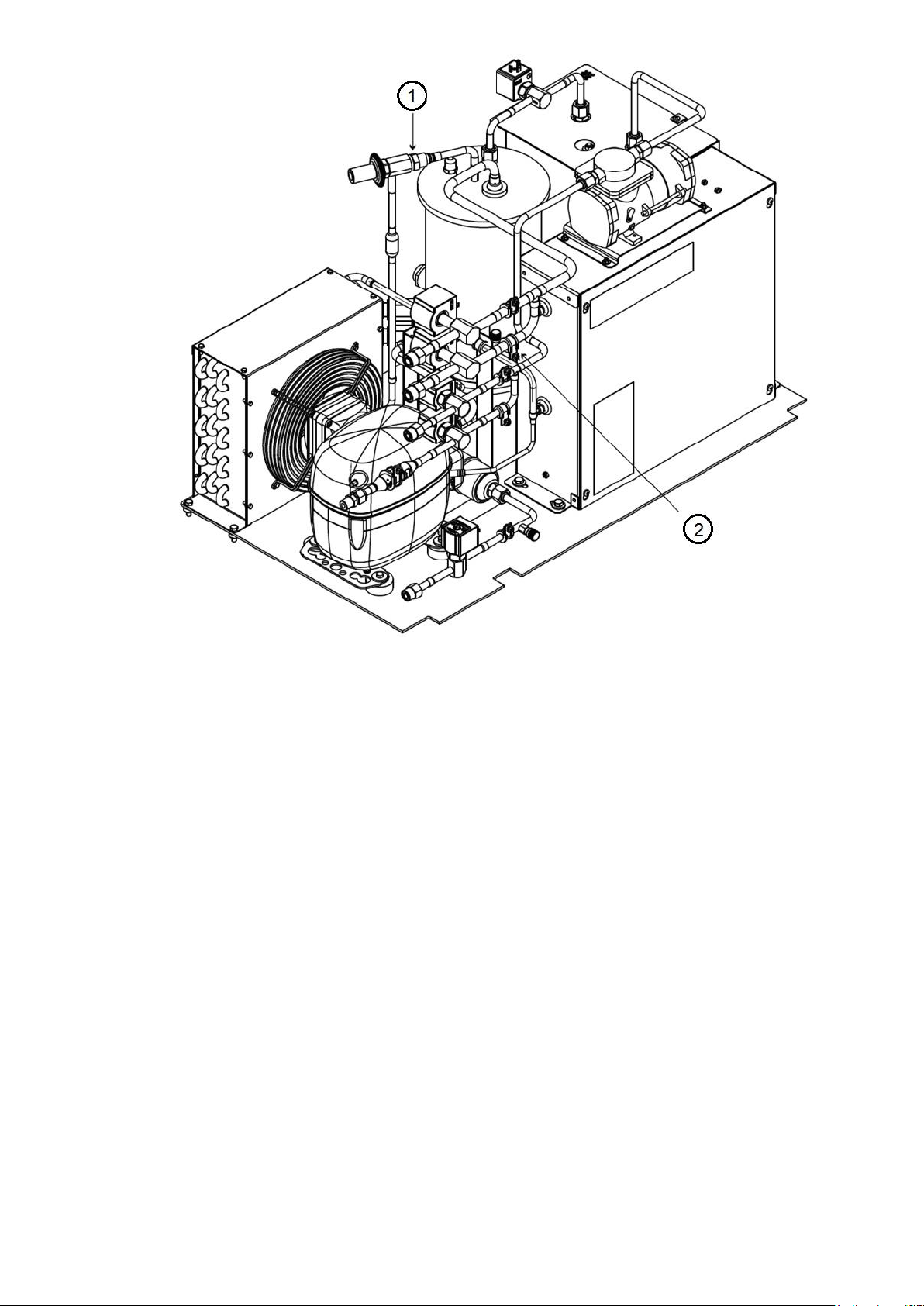
1 : Expansion valve
2 : Suction Schrader valve
Note : Clockwise rotation of expansion valve adjustment screw increases the pressure setting and counterclockwise rotation
decreases pressure setting.
Fig 42 – purge system setting
5.5 Checking the Installation
Use the following instructions to verify the condition of the installation:
1. Turn off, lock out, and tag the input power to the drive.
2. Wait a minimum of 5 minutes for the DC bus to discharge.
3. All wiring should be installed in conformance with the applicable local, national, and international codes.
4. Remove any debris, such as metal shavings from the enclosure.
5. Check that there is adequate clearance around the machine.
6. Verify that the wiring to the terminal strip and the power terminals is correct and that no external voltage
potential are connected to any of the inputs.
7. Verify that all of the VFD power module circuit board connectors are fully engaged and taped in place.
8. Check that the wire size is within terminal specifications and that the wires are tightened properly and
adequately supported.
9. Check that specified branch circuit protection is installed and correctly rated.
10. Check that the incoming power is within ±10% of chiller nameplate voltage.
11. Verify that a properly sized ground wire installed and a suitable earth ground is used. Check for and eliminate
any grounds between the power leads. Verify that all ground leads are unbroken to the power supply. Only a wye
secondary power supply transformer with solidly grounded neutral is acceptable as a power supply to this chiller.
5.6 Check Lubrication Circuit system
Please check condenser float chamber liquid level. If lubrication system works properly, the liquid level sensor
should indicate ON.
76
Page 77
5.7 Charge unit with refrigerant
Compressor frame size
Condenser HX designation
Evaporator HX designation
R-1233zd(E)
charge (+/- 11kg)
DV4
G22, G27, G2C, G2H
G20, G21, G22, G23, G24, G25,
G26, G27, G28, G29,G2A,
G2B, G2C, G2D, G2E, G2F, G2G,
G2H, G2J, G2K
660
G23, G28, G2D, G2J
656
G24, G29
655
G2E, G2K
653
G42, G47, G4C, G4H
G40, G41, G42, G43, G44, G45,
G46, G47, G48, G49,G4A,
G4B, G4C, G4D, G4E, G4F, G4G,
G4H, G4J, G4K
748
G43, G48, G4D, G4J
744
G44, G49
743
G4E, G4K
740
Standard 19DV is shipped with refrigerant but it can also be shipped with holding nitrogen charge of 103 kPa.
Chiller has to be loaded on job site with refrigerant.
IMPORTANT: Turn on the chilled water and condenser water pumps to prevent freezing.
CAUTION: Always operate the condenser and chilled water pumps whenever charging, transferring, or removing
refrigerant from the chiller. Always confirm that water flow is established.
Failure to follow this procedure may result in equipment damage.
CAUTION: The transfer, addition, or removal of refrigerant in spring isolated chillers may place severe stress on
external piping if springs have not been blocked in both up and down directions. Failure to block springs in both up
and down directions could result in severe personal injury and equipment damage.
CAUTION: Always operate the condenser and chilled water pumps during charging operations to prevent freezeups. Damage could result to equipment if condenser and chilled water pumps are not operated during pumpdown or
charging.
WARNING : Always charge refrigerant gas into unit until pressure exceeds water freeze temperature using
PUMPDOWN/ LOCKOUT (located in the Maintenance menu) and TERMINATE LOCKOUT mode on the PIC5+.
Cooler and condenser water pumps must be running to prevent tube freezing.
For R-1233zd(E) water freeze point is exceeded at -15 in. Hg (-51 kPa).
Charge the unit from refrigerant cylinders. Use Table 18 to find expected approximate charge by adding cooler
and condenser charge together. Refer to unit nameplate and E-Cat output for certified values.
Prior to charging ensure the following:
a. Standing vacuum test completed
b. Only initiate refrigerant charging into a deep vacuum
c. Adequate refrigerant supply is available as per unit nameplate. With water pumps running, connect charging
hose from refrigerant cylinder to chiller cooler charging valve. Start with charging gas until the pressure is greater
than the above saturation pressure temperature to avoid refrigerant flashing and potential tube freezing. Once
required pressure is reached switch over to charge liquid by either lifting refrigerant cylinder above charging valve
to allow for gravity feed or if charge isolated in storage tank using pumpout equipment suited for low pressure
refrigerant.
After the machine has been started, adjust charge for optimum machine performance. Operate the chiller at
design load and then add or remove refrigerant slowly until the difference between the leaving chilled water
temperature and the cooler refrigerant temperature reaches design conditions or becomes a minimum. Do not
overcharge. Use the cooler sight glass to determine the correct refrigerant at all times. During steady state
operation at full load, the boiling pool tubes under compressor suction should be covered with liquid refrigerant.
There is no benefit to a refrigerant liquid level higher than the tubes.
Table 18 – refrigerant charge
77
Page 78
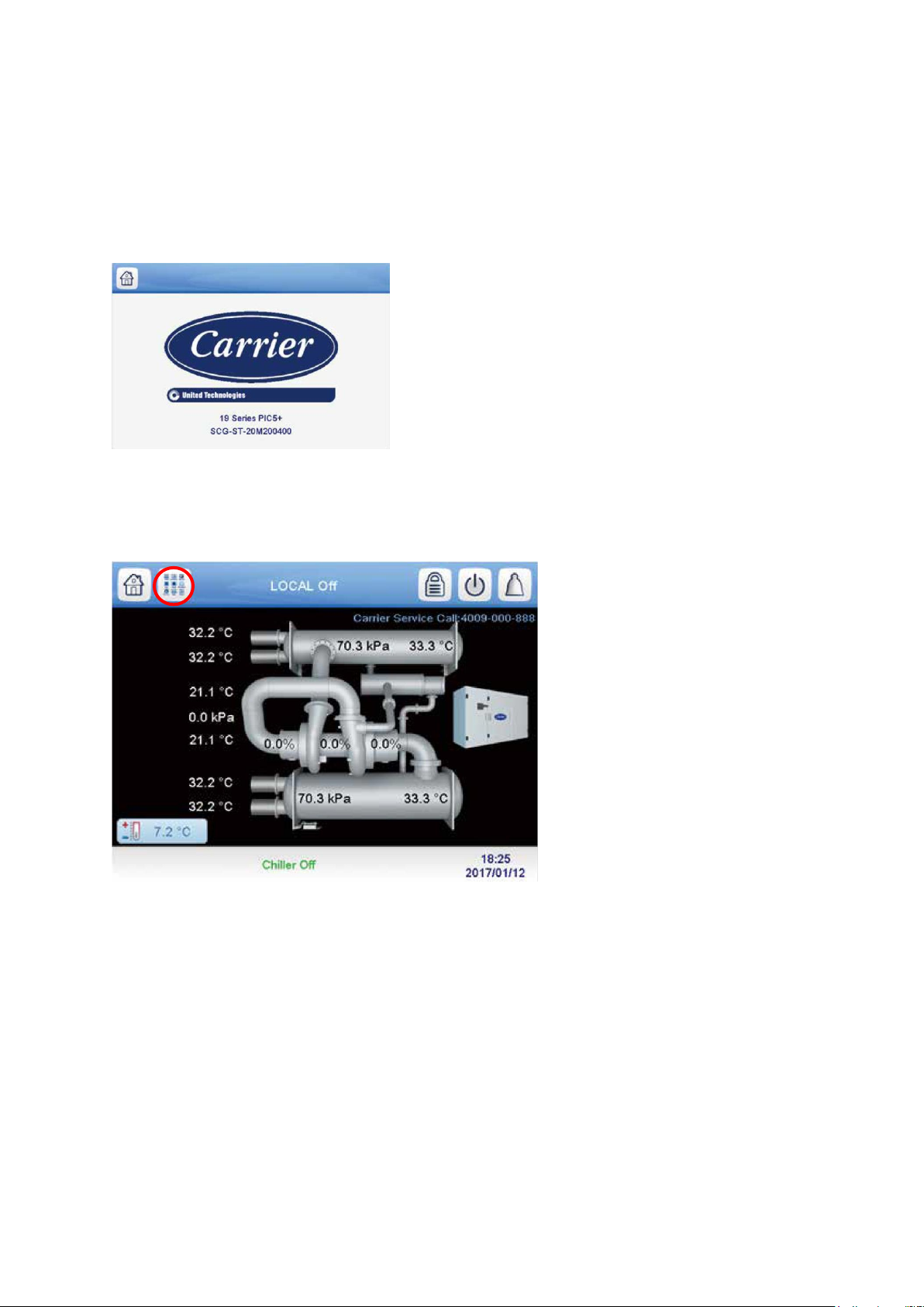
5.8 Software configuration
WARNING: Do not operate the chiller before the control configurations have been checked and a Calibration and
Control Test has been satisfactorily completed. Protection by safety controls cannot be assumed until all control
configurations have been confirmed.
See the 19DV with PIC 5+ Controls Operation and Troubleshooting manual for instructions on using the PIC 5+
interface to configure the 19DV unit. As the unit is configured, all configuration settings should be written down.
The welcome screen is the first screen shown after switching the unit on or after the re-animation of the screen. It
displays the application name as well as current software version number.
Fig 43: Welcome screen
5.8.1 Input the Design Set Points
To access the set point screen, press the Main Menu icon on the home screen. See Fig. 44
Fig 44: main menu icon
The Main Menu screen is displayed. Press the Setpoint Table icon (Fig. 45).
78
Page 79
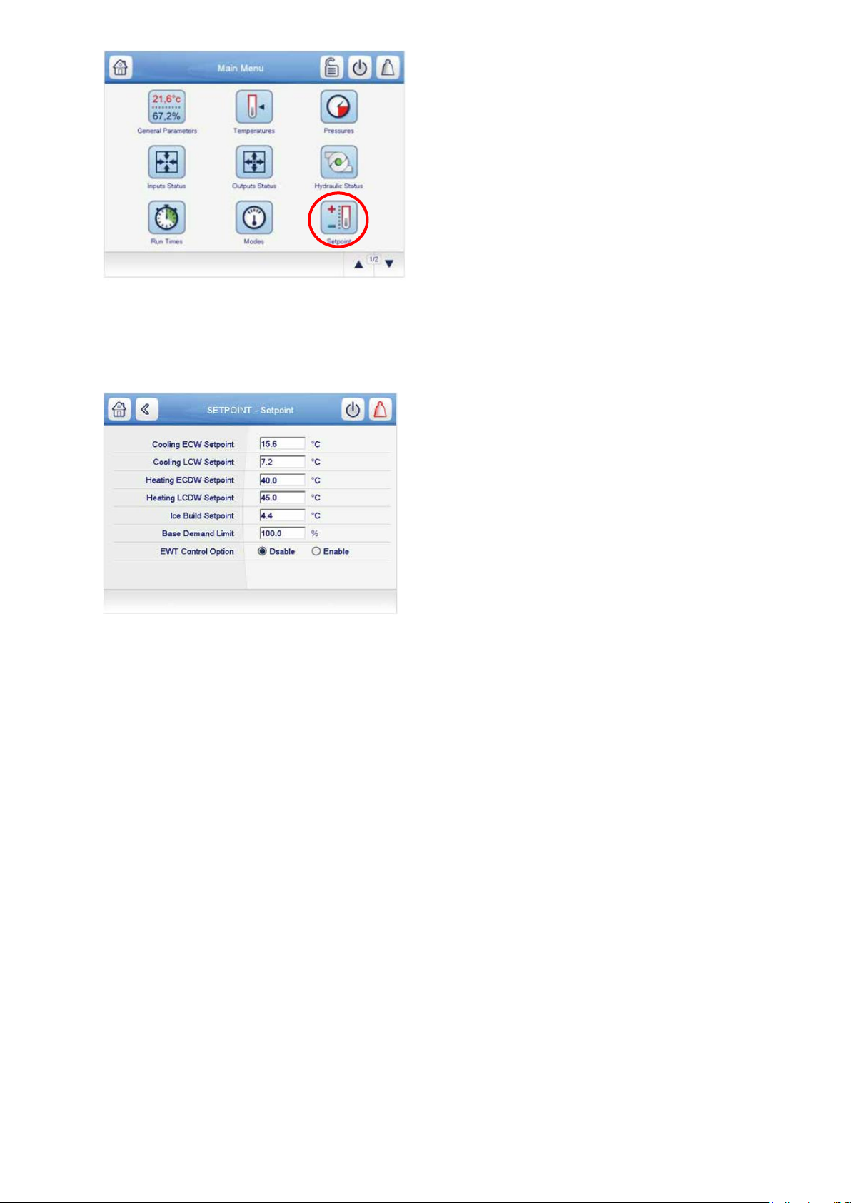
Fig 45: main menu – setpoint table icon
The Setpoint screen is displayed (see Fig. 46). Set the base demand limit set point, and either the LCW set point
or the ECW set point. To set a value, press the appropriate set point, enter the value, and press OK. For more
information, see the PIC5+ Control User Manual.
Fig 46: Setpoint table screen
5.8.2 Input the local occupied schedule
Access the schedule screen and set up the occupied time schedule according to the customer’s requirements. If
no schedule is available, the default is factory set for 24 hours occupied, 7 days per week including holidays. The
Schedule Menu as well as the Holiday Menu can be reached through the Configuration Menu. When the control
mode is LOCAL SCHEDULE, the chiller will be automatically started if the configured local schedule is occupied
and will be automatically shut down by the unoccupied schedule.
The Network Schedule should be configured if a CCN system is being installed. When control mode is
NETWORK, the chiller can be started and stopped by the CHIL_S_S software point as written by other equipment
through the network command and network schedule.
For more information about setting time schedules, please refer to the PIC5+ Control User Manual.
5.8.3 Input service configurations
For specific values or the following configurations, refer to the chiller performance data or job-specific data sheet:
• password
• log in/logout
• input time and date
• service parameters
• equipment configuration
• automated control test
PASSWORD — The PIC 5+ control system provides different levels of access: Basic access, User access,
Advanced User/ Service access and Factory access. User access provides basic access to the chiller controls.
Advanced User access has access to all Service tables, and Factory user has access to factory tables. The PIC
5+ default password configurations are as follows:
• Basic User: No password required
• User: 1111
• Advanced User / Service Access: 2222
• Factory: 4444
79
Page 80
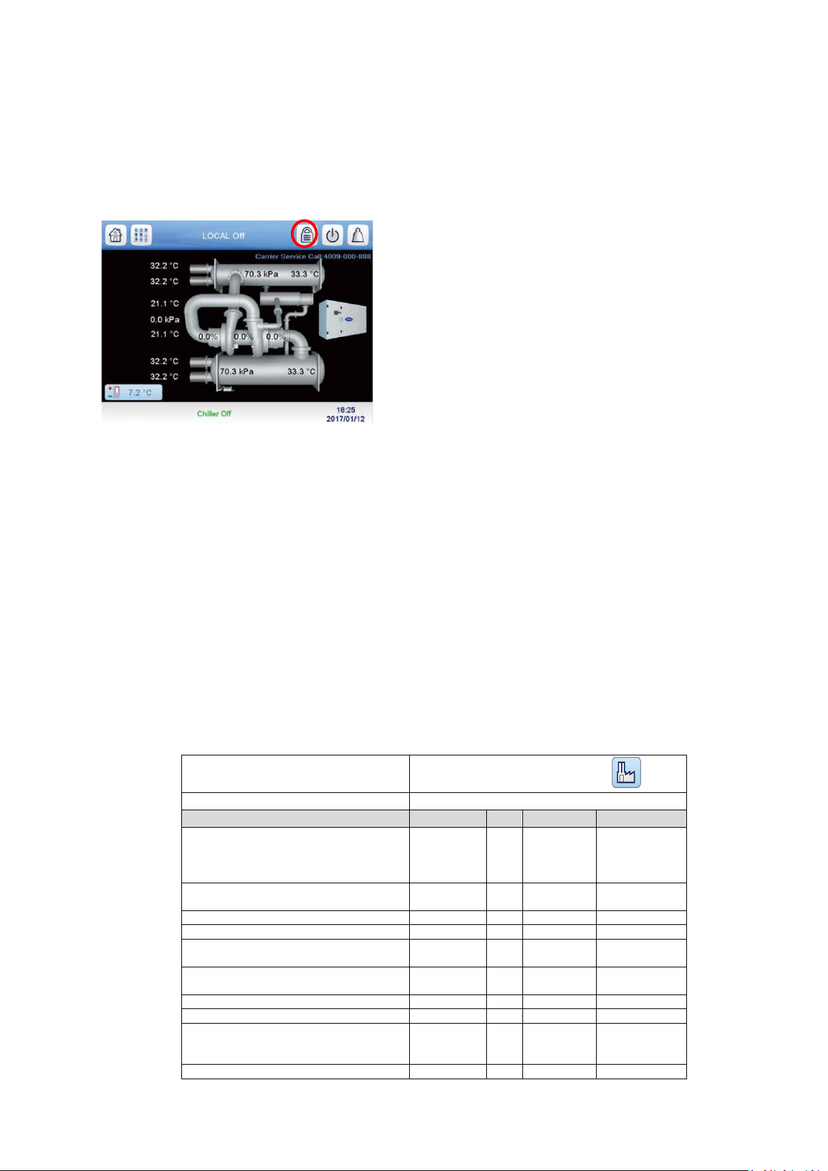
TABLE
FACTORY - Factory Parameters
Access Menu
Configuration Menu / Factory parameters
Setting
Range
Units
Default value
Settings value
Chiller Type
19XR6/7=0,
19XR2~E/D/V=1,
19DV=2
0 to 2
- 0 2
Unit Type
Cool Only=0,Heat Mach=1
0 to 1
- 0 per selection
Comp (Single = 0, Dual = 1)
0 to 1
- 1 1
Chilled Medium Type Water/brine
Water/Brine
-
Water
per selection
Cond Shell Side MAWP
185PSI=0, 300PSI=1
0 to 1
- 0 0
19DV Comp Design Pressure
300 kPa = 0, 500 kPa= 1
0 to 1
- 0 0
Country Code
0 to 999
-
86
33
Free Cooling Option
No/yes
-
NO
per selection
VFD Option No=0,FS VFD=1,Carrier=2
RockwellLF2=3, Eaton=4, Rockwell Std=5,
ABB=6, Danfoss=7
0 to 7
-
0
1, 3, or 7 per
selection
IOB3 option (19XR2~E/D/V)
No/yes
-
Yes
Yes
When accessing the SERVICE tables, a password must be entered. The password can be changed from the
Configuration Menu. USER CONFIGURATION allows change of the User access password. SERVICE
PARAMETERS allows change of the Advanced User/Service password, and FACTORY PARAMETERS allows
change of the Factory password. Passwords must be 4 digits (from 1111 to 9999).
IMPORTANT: Be sure to remember the password. Retain a copy for future reference. Without the password, access
to the SERVICE menu will not be possible unless accessed by a Carrier representative.
LOGIN/LOGOUT — Press the lock icon on the home screen to enter the password.
Fig 47: Lock icon
The User Login Screen is displayed. Enter the password on this screen. The language and system of
measurement can also be changed on this screen. For details, see the PIC 5+ Controls Operation and
Troubleshooting guide.
INPUT TIME AND DATE — Set day and time and if applicable Holidays through MAIN MENU CONFIGURATION MENU and then select appropriate icon. See the Controls Operation and Troubleshooting
guide for details. Because a schedule is integral to the chiller control sequence, the chiller will not start until the
time and date have been set.
NOTE: The date format is MM-DD-YY for English units and DD-MM-YY for SI units.
MODIFY CONTROLLER IDENTIFICATION IF NECESSARY — The CCN address can be changed from the
Configuration Menu. Change this address under CONTROL IDENTIFICATION for each chiller if there is more than
one chiller at the jobsite. Write the new address on the PIC5+ Touch Screen module for future reference.
CONFIGURE TABLES — Access the related tables through MAIN MENU CONFIGURATION MENU to modify or
view job site parameters shown in 19DV Configuration tables. Table 19 should be verified or configured during
startup/commissioning. Consult chiller nameplates as indicated.
80
Page 81
IOB 4 Option
No/yes
-
No
Yes
Guide Vane1 Type
Digital=0, Analog=1
- 0 1
VFD Feedback Voltage Sel
0-5V=0, 0-10V=1
- 0 0
Marine option
Disable/Enable
-
Dsable
Dsable
Power Request option
Disable/Enable
-
Dsable
Dsable
Cont. Power Request
Disable/Enable
-
Dsable
Dsable
Purge System Option
Disable/Enable
-
Dsable
Enable
Liquid bypass Option
Disable/Enable
-
Dsable
per selection
Heat Reclaim Option No=0, Full=1, Partial=2
0 to 2
- 0 0
TABLE
CFGSURGE - Surge Correction Config
Access Menu
Configuration Menu / Surge Correction Config
Setting
Default value (SI units)
Settings value (SI)
Surge Line Configuration
PR = 0, Delta T = 1 0 1
IGV1 Pos Configuration
Degree = 0, Percentage = 1
0
0
Surge Delta Ts max
38,9°C
selection output
Surge Delta Ts min
25°C
selection output
PR at Full Load Opening
3
3
PR at Minimum opening
1.5
1.5
IGV1 Full Load Open Deg
88
88
Sound Ctrl IGV1 Open Deg
27
27
IGV1 Minimum open Deg
2
2
IGV1 Actuator max deg
109
94
IGV1 minimum position
5
5
IGV1 Full load Position
100%
93.6%
Surge Line Offset
0.8
0.8
Surge Line Lower DB
0.6
0.6
Surge Line Upper DB
0.6
0.6
Surge Line Shape Factor
-0.01
selection output
Sound Line Shape Factor
0.01
selection output
Surge Line speed factor
2
selection output
Surge delay time
15 sec
15 sec
Surge Time Period
8 min
8 min
Surge Delta Amps %
20%
20%
Rampdown Factor
0.1
0.1
GV1 Close Step Surge
2%
2%
VFD Speed Step Surge
1.50%
1.50%
EC valve Step Surge
4%
4%
Surge Profile Step
0.6
0.6
Surge Profile Offset
1.7
1.7
High Efficiency Mode
Enable
Enable
High Noise Alert
Disable
Disable
TABLE
CFGLIMIT - Protective Limit Config
Access Menu
Configuration Menu / Protective Limit Config
Setting
Default value (SI units)
Settings value (SI)
Evap Approach Alert
2.8
2.8
Cond Approach Alert
3.3
3.3
Cond Press Override Low
965.3
965.3
Cond Press Override High
1723.8
1723.8
Cond Press Cutout Low
1103.2
1103.2
Cond Press cutout high
1896.1
1896.1
Evap Override Delta T
1.4
2.6
Evap Refrig Trippoint
0.6
-1
High evap press override
965.3
965.3
High evap press cutout
1137.7
1137.7
Hi Evap Pre override DV
379.2
379.2
Hi Evap Pre Cutout DV
406.8
406.8
Cond Pre Override DV 44
180
180
Cond Pre Cutout DV 44
206.9
206.9
81
Page 82
Cond Pre Override Dv 72
379.2
379.2
Cond Pre Cutout DV 72
406.8
406.8
Condenser freeze point
1.1
1.1
Comp discharge Alert
93.3
93.3
Comp Motor Temp Override
93.3
93.3
Comp Bearing Temp Alert
79.4
79.4
Comp Bearing Temp trip
85
85
Comp Bearing Alert R6/7
98.9
98.9
Comp Bearing Trip R6/7
104.4
104.4
Comp Bearing Alert DV
40
40
Comp bearing Trip DV
50
50
Minimum Brine LWT
1.1
1.1
Heating LWT Protect Set
6
6
Liquid Bypass Temp Band
1.7
1.7
Evap Flow Delta P Cutout
35
Jobsite specific
Cond Flow Delta P Cutout
35
Jobsite specific
Cond Hi Flow DP Limit
344.7
Jobsite specific
Cond Hi Flow Alarm
Disable
Disable
TABLE
General Configuration
Access Menu
Configuration Menu / General Configuration
Setting
Default value
(SI units)
Settings value (SI)
User password
1111
1111
Stop to Start Delay 2 2
Start to Start Delay
15
15
Demand limit Type (Base demand=0, 4-20mA=1)
0
0
Pulldown rampe type (Temp=0, Load=1)
1
1
Demand limit source (Amps=0, kW=1)
0
0
TABLE
CFGEVFD - General VFD Config
Access Menu
Configuration Menu / General VFD Config
Setting
Default value (SI units)
Settings value (SI)
Comments
VFD gain
0.75
0.75
VFD Max Speed Per
100%
100%
VFD Min Speed Per
70%
55%
VFD Start Speed Per
100%
100%
VFD Current limit
250 A
872
Max current output for UM VFD
VFD Load Current 20mA
200 A
200 A
Comp Frequency 100%
50 Hz
50 Hz
VFD load current input
Enable
Enable
TABLE
19DV Configure
Access Menu
Configuration Menu / 19DV Config
Setting
Default value (SI units)
Settings value (SI)
Pressure sensor option (Tianmu=0,
Texas=1, Sensata=2)
0
0
Motor pole pair 1 1
IGV2 Travel limit
100%
96.0%
IGV2 Minimum Deg
2
2
IGV2 Full Load open Deg
88
90
IGV2 Actuator Max Deg
94
94
IGV2 Deg @IGV1 20 Deg
28.1
28.1
IGV2 Deg @IGV1 30 Deg
37.2
37.2
IGV2 Deg @IGV1 50 Deg
71.6
71.6
Comp Based Speed Hz
80.5
80.5
Purge Regen Lasting time
120
120
Daily PG Pumpout Limit
50 min
50 min
DSH_Req param VFD F
0.5
0.5
DSH_Req param VFD 2nd
-0.0059
-0.0059
82
Page 83
DSH_Req param VFD 1st
0.9427
0.9427
DSH_Req param VFD Const
-34.5
-34.5
DSH_Req param IGV F
0.2
0.2
DSH_Req param IGV 2nd
0.0046
0.0046
DSH_Req param IGV 1st
-0.562
-0.562
DSH_Req param IGV Const
21
21
DSH_Req param Lift F
0.3
0.3
DSH_Req param Lift 2nd
0.0006
0.0006
DSH_Req param Lift 1st
-0.1104
-0.1104
DSH_Req param Lift Const
5.5
5.5
Liquid Bypass Temp Diff
11.1
11.1
Liquid Bypass Cond Appro
2.8
2.8
Bearing Sub Cooling
-5
-5
Purge Discharge Temp
-15.6
-15.6
Purge Drainage Temp
-11.1
-11.1
CLT Factory Option
disable
enable
Refrig Lube Option 7
disable
disable
TABLE
CFGUMVFD - UM VFD Configuration
Access Menu
Configuration Menu / UM VFD Configuration
Setting
Default value (SI units)
Settings value (SI)
Comments
Compressor Speed 100%
50 Hz
98 Hz
Nameplate
Rated line voltage
460 V
400 V
Nameplate
Motor Nameplate Current
200 A
Nameplate
Motor Rated Load Current
200 A
Nameplate
Motor Nameplate Voltage
460 V
Nameplate
Motor Nameplate RPM
3000 rpm
Nameplate
Motor Nameplate KW
1500 kW
Nameplate
Skip Frequency 1
102 Hz
102 Hz
UM Rockwell LF2
Skip Frequency 2
102 Hz
102 Hz
UM Rockwell LF2
Skip Frequency 3
102 Hz
102 Hz
UM Rockwell LF2
Skip Frequency Band
0 Hz
0 Hz
Increase Ramp Time
30 sec
30 sec
Decrease Ramp Time
30 sec
30 sec
Line Voltage % Imbalance
0.1
10%
Line Volt Imbalance Time
10 sec
10 sec
Line Current % Imbalance
0.4
40%
Line Current Imbal Time
10 sec
10 sec
Motor Current % Imbalance
0.4
40%
Motor Current Imbal Time
10 sec
10 sec
Single Cycle Dropout
Dsable
Dsable
PWM Frequency (0=2 k Hz, 1=4 k Hz)
0
0
Restore Defaults
No
No
LEN Comm Timeout
10 sec
10 sec
Modbus Comm Timeout
2 sec
2 sec
Gateway Modbus Baud Rate
4800 = 1, 9600 = 2, 19200 = 3,
38400=4 2 2
Number of GDCBs
0
0
GDCB Startup Delay
50%
50%
TABLE
CONF_OPT - Option configuration
Access Menu
Configuration Menu / Option Configuration
Setting
Default value (SI units)
Settings value (SI)
Auto Restart Option
Dsable
job site specific
Common Sensor Option
Dsable
job site specific
EC Valve Option
No=0, Cont.=1, ON/OFF=2, mA=3
0
2 if selected
EC valve selection
Disable =0, Surge=1, Low Load=2, Comb=3
0
job site specific
ECV Open IGV1 Position
5%
5% (adjust as required)
ECV Close IGV1 Position
10%
10% (adjust as required)
ECV Off DT for Low Load
2,2 °C
2,2 °C (adjust as required)
83
Page 84
ECV On DT for Low Load
1,1 °C
1,1 °C (adjust as required)
ECV Low Load DB
0,6 °C
0,6 °C (adjust as required)
Head Pres Valve Option
Dsable
job site specific
Head Pres Delta P 0%
172,4 kPa
172,4 kPa (adjust as required)
Head Pres Delta P 100%
344,7 kPa
344,7 kPa (adjust as required)
Head Pressure Min Output
0%
0% (adjust as required)
Tower Fan High Setpoint
24 °C
24 °C (adjust as required)
Refrig Leakage Option
Dsable
job site specific
Refrig Leak Alarm mA
20 mA
20 mA (adjust as required)
Oil EXV Option
Dsable
Dsable
Oil Temp High Threshold
50 °C
N/A
Oil Temp Low Threshold
45 °C
N/A
Gas Torque Factor 1 1
Guide Vane/SRD Factor
0.95
0.95
Power Recovery Timeout
15 min
15 min
Condenser Flush Alert
Dsable
Dsable
Customer Alert Option
Dsable
job site specific
Ice Build Option
Dsable
job site specific
Ice Build Recycle
Dsable
job site specific
Ice Build Termin Source
Temp=0,Contact=1,Both=2
0
job site specific
Water Pressure Option
No=0, Flow Meter=1, Water Pres. D=2
0
1
Water Flow Measurement
No=0, Flow Meter=1,Water PD=2
0
0
Water Flow Determination
Sat Temp=0,Flow Switch=1
0
job site specific
Water Flow at 4mA
0 l/sec
adjust as required
Water Flow at 20mA
0 l/sec
adjust as required
Evap Flow Rate Baseline
0 l/sec
adjust as required
Evap Pres Drop Baseline
0 kPa
adjust as required
Cond Flow Rate Baseline
0 l/sec
adjust as required
Cond Pres Drop Baseline
0 kPa
adjust as required
Water Pres Drop @20mA
68,95 kPa
adjust as required
Max Oil Pressure Diff
344,7 kPa
N/A
Oil Pump VFD Max Step
7%
N/A
Vapor Source SV Delay
5 min
N/A
Vapor Source SV Option
Dsable
N/A
Liquid Bypass Selection
Dsable
per selection
Purge on Idle option
Dsable
adjust as required for force
Evap Liquid Temp Opt
Enable
N/A
Evap App Calc Selection
Sat Temp=0, Ref Temp=1
1
1
TABLE
SERVICE - Service Parameters
Access Menu
Configuration Menu / Service parameters
Setting
Default value (SI units)
Settings value (SI)
Atmospheric Pressure
99,978 kPa
*
GV1 Travel Limit
80.70%
*
GV1 Closure at Startup
4.00%
*
Controlled Fluid DB
0,6°C
*
Derivatived EWT Gain 2 *
Proportional Dec Band
6
*
Proportional Inc Band
6.5
*
Maximum GV Movement
2.00%
*
Demand Limit at 20 mA
40%
*
Demand Limit Prop Band
10%
*
Amps or KW Ramp per Min
5%
*
Temp Ramp per Min
1,7°C
*
Recycle Shutdown Delta T
0,6°C
*
Recycle Restart Delta T
2,8°C
*
Damper Valve Act Delay
2 min
*
Damper Valve Close DB
34,5 kPa
*
Damper Valve Open DB
89,6 kPa
*
Damper Action Delta T
3,9°C
*
Oil Press Verify Time
40 sec
*
Soft Stop Amps Threshold
70%
*
Water flow verify Time
5 min
*
Power calibration factor 1 *
Purge Active Temp SP
18.3
*
84
Page 85
Enable Excessive Starts
No
*
Oil Stir Cycle (19XR6/7)
No Stir = 0, 30s/30m = 1, 1m/4h = 2, Comb.
0&1=3
1
*
TABLE
SETPOINT
Access Menu
Main Menu / Setpoint
Setting
Default value (SI units)
Settings value (SI)
Cooling ECW Setpoint
12
job site specific
Cooling LCW Setpoint
7
job site specific
Heating ECDW Setpoint
40
job site specific
Heating LCDW Setpoint
45
job site specific
Ice Build setpoint
4.4
job site specific
Base Demand limit
100%
100%
EWT Control Option
Disable
job site specific
TABLE
CONF_IOB - IOB configuration
Access Menu
Configuration Menu / IOB Configuration
Setting
Default value
Settings value
IOB1 AI#1 Type
4
4
Entering chilled water temperature
IOB1 AI#2 Type
4
4
Leaving chilled water temperature
IOB1 AI#3 Type
4
4
Entering condenser water temperature
IOB1 AI#4 Type
4
4
Leaving condenser water temperature
IOB1 AI#9 Type
2
0
nothing
IOB1 AO#1 Type
1
1
Chiller status output mA
IOB2 AI#1 Type
4
4
Motor winding temperature 1
IOB2 AI#2 Type
4
0
IOB2 AI#3 Type
4
2
EC option
IOB2 AI#4 Type
0
0
IOB2 AI#8 Type
0
2
Auto Demand limit input
IOB2 AI#9 Type
0
0
No Refrigerant leak sensor
IOB2 AI#10 Type
5
1
IOB2 AO#1 Type
1
1
Guide Vane1 output
IOB2 AO#2 Type
1
0
not used
IOB3 AI#1 Type
4
4
1st stage bearing temp
IOB3 AI#2 Type
4
4
2nd stage bearing temp
IOB3 AI#3 Type
4
4
Bearing ref supply temp
IOB3 AI#4 Type
4
2
Guide Vane 2 actual position
IOB3 AI#5 Type
0
4
Remote Reset Sensor
IOB3 AI#6 Type
5
2
Guide Vane 1 Actual Pos
IOB3 AI#8 Type
0
0
Auto Water Temp Reset
IOB3 AI#9 Type
0
0
Common CHWR Temp, not used
IOB3 AI#10 Type
0
0
not used
IOB3 AO#1 Type
1
1
Head Pressure Output
IOB3 AO#2 Type
1
0
not used
IOB4 AI#3 Type
0
1
Entering Evap water pressure
IOB4 AI#4 Type
0
1
Leaving Evap water pressure
IOB4 AI#5 Type
0
1
Entering Cond water pressure
IOB4 AI#6 Type
0
1
Leaving Cond water pressure
IOB4 AI#7 Type
0
0
not used
IOB4 AI#10 Type
0
0
not used
ISM Input Enable
Disable
Disable
* : Most Service Parameters do not require any change from default. Adjust as required.
Information for IOB input (AI) type as below:
0 : not used
1 : 0 – 5V
2 : 0 – 20 mA
3 : 10 K
85
Page 86
4 : 5 K
POINT
STATUS
DEFAULT
UNITS
DESCRIPTION
LOW
LIMIT
HIGH
LIMIT
LEN
FORCE
1
QCK_TEST
0~1
0
Quick Test Enable
0 1 X 2 Q_OILH
0~1
0
Quick Test Oil Heater
0 1 X
3
Q_OILP
0~1
0
Quick Test Oil/Ref Pump
0 1 X 4 OP_PASS
NO/YES
0
Ref Press Test Passed
0 1 5 OIL_PDQ
-6.7~420.0
kPa
Ref Pump Delta Press
-6.7
420 6
Q_EXV
0.0~100.0
0
Quick Test Oil EXV
0
100
X
7
Q_HDP
0.0~100.0
0
%
Quick Test Head Val Pos
0
100
8
Q_CHST
4.0~20.0
0
mA
Quick Test Chiller Stat
4
20
9
Q_GV1POS
0.0~100.0
0
%
Guide Vane 1 Tested Pos
0
100
10
Q_GV2POS
0.0~100.0
0
%
Guide Vane 2 Tested Pos
0
100
11
Q_GV1OP
0~1
0
Quick Test GV1 Open
0 1 X
5 : Resist
Information for IOB output (AO) type as below:
0 : disable
1: 0-20ma
2 : 0-10V
Table 19 - PIC 5 - 19DV CONFIGURATION (example for SW build SCG-SR-20M200400)
5.8.4 Field Set Up and Verification
IMPORTANT: Some parameters are specific to the chiller configuration and will need to be verified prior to
operation. All command functions must be initiated from the HMI.
Use the HMI touch screen to confirm that the VFD values match the chiller parameter labels and Chiller Builder
design data sheet. The VFD values can be located from MAIN MENU >> CONFIGURATION MENU.
LABEL LOCATIONS — verify the following labels have been installed properly and match the chiller requisition:
• Chiller identification nameplate — Located on control panel.
• VFD Nameplate data - located on the VFD.
MODIFY EQUIPMENT CONFIGURATION IF NECESSARY
— The EQUIPMENT SERVICE table has screens to select, view, or modify parameters. Carrier’s certified
drawings have the configuration values required for the jobsite. Modify these values only if requested.
Modifications can include:
• Chilled water reset
• Entering chilled water control (Enable/Disable)
• 4 to 20 mA demand limit
• Auto restart option (Enable/Disable)
• Remote contact option (Enable/Disable)
See the 19DV with PIC5+ Controls Operation and Troubleshooting guide for more details about these functions;
see the Control Panel Schematic for field wiring.
5.9 Perform a control test (quick calibration / quick test)
Check the safety controls status by performing an automated controls test. First, perform a Quick Calibration Test
(Path Main Menu→ Quick Calibration. This is required for all modulating analog actuators. Upon successful
calibration go Main Menu → Quick Test and verify operation on desired components. Note that this is a very
useful feature for troubleshooting. (The QUICK TEST screens can only be accessed when the chiller is in STOP
mode.) On the QUICK TEST table screen, select a test to be performed.
The Quick Test checks all outputs and inputs for proper functionality. In order to successfully proceed with the
controls test, the compressor must be off, no alarms showing, and voltage should be within ±10% of rating plate
value. Each test asks the operator to confirm the operation is occurring and whether or not to continue. If an error
occurs, the operator can try to address the problem as the test is being done or note the problem and proceed to
the next test.
If during the control test the guide vanes do not open, check the low pressure alarm, which shall not be active. (An
active low pressure alarm causes the guide vanes close.)
The refrigerant pump test will not energize the refrigerant pump if cooler pressure is below–89.63 kPa.
When the controls test is finished the test stops and the QUICK TEST menu displays. If a specific automated test
procedure is not completed, access the particular control test to test the function when ready. Disable the Quick
Test feature when testing is complete.
86
Page 87
12
Q_GV1CL
0~1
0
Quick Test GV1 Close
0 1 X
13
Q_GVSRD
DISABLE/ENABLE
0
GV1/SRD Joint Test
0 1 X
14
Q_SRD
0.0~100.0
0
%
Quick Test Diffuser Pos
0
100
X
15
Q_GV1ACT
Guide Vane 1 Actual Pos
16
Q_DIFTGT
Diffuser Target Pos
17
Q_HGBPOP
0~1
0
Quick Test ECV Open
0 1 X
18
Q_HGBPCL
0~1
0
Quick Test ECV Close
0 1 X
19
Q_HGBP_T
0.0~100.0
%
EC Valve Tested Pos
0
100
X
20
Q_DMPOP
0~1
0
Quick Test Damper Open
0 1 X
21
Q_DMPCL
0~1
0
Quick Test Damper Close
0 1 X
22
Q_ALM
0~1
0
Quick Test Alarm Output
0 1 X
23
Q_ALE
0~1
0
Quick Test Alert Output
0 1 X
24
Q_CDWP
0~1
0
Quick Test Cond Pump
0 1 X
25
CDW_FLOW
NO/YES
0
Condenser Water Flow
0 1
26
Q_CHWP
0~1
0
Quick Test Chilled Pump
0 1 X
27
CHW_FLOW
NO/YES
0
Chilled Water Flow
0 1
28
CDW_DT
-40.0~245.0
0
° C
Condenser Water Delta T
-40
245
29
CHW_DT
-40.0~245.0
0
° C
Chilled Water Delta T
-40
245
30
Q_LLCEXV
0.0~100.0
0
%
Quick Test LLC EXV
0
100
X
31
Q_VFDCOL
0~1
0
Quick Test VFD Cooling
0 1 X
32
Q_VAPLSV
0~1
0
QCK TST Vapor Venting SV
0 1 X
33
Q_VSSV
0~1
0
Quick Test Vapor SV
0 1 X
34
Q_CONDSV
0~1
0
Quick Test Condenser CV
0 1 X
35
Q_EVAPSV
0~1
0
Quick Test Evaporator CV
0 1 X
36
Q_OPRLUB
0~1
0
QCK TST EvapDrain CV
0 1 X
37
Q_PRELUB
0~1
0
QCK TST Cond Drain CV
0 1 X
38
Q_CDPSV
0~1
0
Quick Test Purge Cond SV
0 1 X
39
Q_CMPSV
0~1
0
Quick Test Purge Comp SV
0 1 X
40
Q_POPSV
0~1
0
Quick Test Pumpout SV
0 1 X
41
Q_DRPSV
0~1
0
Quick Test Drainage SV
0 1 X
42
Q_RGPSV
0~1
0
Quick Test Rege SV
0 1 X
43
Q_DCPSV
0~1
0
Quick Test Discharge SV
0 1 X
44
Q_PVPSV
0~1
0
Quick Test Vacuum Pump
0 1 X
45
Q_PCPSV
0~1
0
Quick Test Purge Comp
0 1 X
46
Q_PHPSV
0~1
0
Quick Test Purge Heater
0 1 X
47
Q_MRC
0~1
0
Motor Rotation Check
0 1 X
48
Q_MRC_ST
Check State
IDLE=0, PreLub=1
Rotat=2, PosLub=3, End=4
49
Q_ECBP
0~1
0
Quick Test Eco Bypass
0 1 X
50
Q_ECONIV
0~1
QCK TST Eco Isolation
0 1 X
51
Q_CONDCV
0~1
QCK TST Cond Filling VLV
0 1 X
52
Q_LOWFAN
0~1
0
Quick Test Lo Tower Fan
0 1 X
53
Q_HIFAN
0~1
0
Quick Test Hi Tower Fan
0 1 X
Table 20 - PIC 5 – QUICK TEST LIST
5.9.1 Cooler and condenser pressure transducer and waterside flow device calibration
(Waterside Device Optional with IOB Inputs Available) — Calibration can be checked by comparing the pressure
readings from the transducer to an accurate refrigeration gage reading. The transducer can be checked and
calibrated at 2 pressure points.
These calibration points are 0 psig (0 kPa) and between 10 psig (68.9 kPa) - 30 psig (206.8 kPa). To calibrate
these transducers:
1. Shut down the compressor and the cooler and condenser pumps.
NOTE: There should be no flow through the heat exchangers.
2. Disconnect the transducer in question from its Schrader fitting for cooler or condenser transducer calibration.
For pump pressure or bearing pressure or flow device calibration keep transducer in place.
NOTE: If the cooler or condenser vessels are at 0 psig (0 kPa) atmospheric pressure, the transducers can be
calibrated for zero without removing the transducer from the vessel.
3. Access the PRESSURE screen from the Main Menu and view the particular transducer reading (the cooler
pressure, condenser pressure, economizer pressure, pump inlet pressure, pump outlet pressure, bearing inlet
pressure, bearing outlet pressure). To calibrate a device, view the particular reading on the screen. It should read
0 kPa). If the reading is not 0 kPa, but within 35 kPa, the value may be set to zero while the appropriate
transducer parameter is highlighted. The value will now go to zero. No high end calibration is necessary for REF
PUMP DELTA P or flow devices. If the transducer value is not within the calibration range, the transducer will
return to the original reading. If the pressure is within the allowed range (noted above), check the voltage ratio of
the transducer. To obtain the voltage ratio, divide the voltage (dc) input from the transducer by the supply voltage
signal (See Maintenance Others in Maintenance Menu) or measure across the positive (+ red) and negative (–
black) leads of the transducer. The voltage ratio must be between 0.80 and 0.11 for the software to allow
calibration. Rotate the waterside flow pressure device from the inlet nozzle to the outlet nozzle and repeat this
87
Page 88

step. If rotating the waterside flow device does not allow calibration then pressurize the transducer until the ratio is
within range. Then attempt calibration again.
4. A high pressure point can be calibrated between 10-30 psig (68.9 -206.8 kPa) by attaching a regulated pressure
source (usually from a nitrogen cylinder with high resolution pressure gage). The high pressure point can be
calibrated by accessing the appropriate transducer parameter on the PRESSURES screen, highlighting the
parameter, then increasing or decreasing the value to the exact pressure on the refrigerant gage.
Pressures at high altitude locations must be compensated for, so the chiller temperature/pressure relationship is
correct. This is set in the Service Parameters (Configuration Menu). The PIC5+ does not allow calibration if the
transducer is too far out of calibration. In this case, a new transducer must be installed and re-calibrated.
IMPORTANT: When screen display calibration is complete, do not depress calibration Enable/Disable since the new
values will be deleted. Values are kept by exiting the pressure sensor table.
6. INITIAL START-UP
6.1 Preparation
Before starting the chiller, verify:
1. Power is on to the VFD, chiller control panel, water pumps, and other equipment as required.
2. Cooling tower water is at proper level and at-or-below design entering temperature.
3. Chiller is charged with refrigerant and all refrigerant valves are in their proper operating positions.
4. Valves in the evaporator and condenser water circuits are open and flow is as per design.
NOTE: If the pumps are not automatic, ensure water is circulating properly.
6.2 Check Motor Rotation
1. Close the VFD enclosure door.
2. Apply 3-phase power to drive.
3. The VFD checks for proper phase rotation as soon as power is applied to the starter and the PIC5+ controls
power up.
4. An alarm message will appear on the HMI screen if the phase rotation is incorrect. If this occurs reverse any 2
of the 3 incoming power leads to the starter and reapply power. The motor is now ready for a rotation check.
5. Go to Main Menu, Quick Test and Enable Quick Test following by enable Motor Rotation Check. This starts the
following sequence:
a. Fully open the first IGV.
b. Open evaporator control valve, condenser drain valve, close condenser control valve, and evaporator control
valve. Run refrigerant pump for 30 seconds.
c. Start the motor and ramp to 5 Hz in 10 seconds.
d. Once the motor speed reaches 5 Hz, stop motor.
e. Stop refrigerant pump 1 minute after motor speed reaches 5 Hz, then reset all 4 refrigerant lubrication valves to
close.
f. Three minutes after motor speed reaches 5 Hz, close first IGV.
Status can be followed in Quick test as Check State IDLE=0, PreLub=1, Rotat=2, PosLub=3, End=4.
6. When the VFD is energized and the motor begins to turn, check for clockwise motor rotation through first stage
sight glasses.
IMPORTANT: Do not check motor rotation during coastdown. Rotation may have reversed during equalization of
vessel pressures.
CORRECT MOTOR ROTATION IS CLOCKWISE WHEN VIEWED THROUGH SUCTION PIPE LEADING TO
COMPRESSOR 1ST STAGE SIGHT GLASS.
When rotation checking, do not let machine develop condenser pressure. Check rotation immediately. Allowing
condenser pressure to build or checking rotation while machine coasts down may give a false indication due to
gas pressure equalizing through compressor.
88
Page 89

6.3 Check Refrigerant Lube
1. In Quick Test the refrigerant lube pressure can be checked. First open cooler valve and condenser drain valve,
then run the refrigerant pump. Usually the pressure drop across bearing is above 55 kPa. If the bearing pressure
drop is negative, please check pump rotation. If bearing pressure drop is below 55 kPa, please check if the
moisture filter is clogged.
2. Press the Stop button and listen for any unusual sounds from the compressor as it coasts to a stop.
6.4 To Prevent Accidental Start-Up
A chiller STOP override setting may be entered to prevent accidental start-up during service or whenever
necessary. From the Main Menu, access the General Parameters Menu and use the down arrow to reach Stop
Override on the GENUNIT table. Change Stop Override to Yes; then execute the command by touching the
lightning button. The message “ALM-276 Protective Limit - Stop Override” will appear in the Home Screen
message area. To restart the chiller, access the same screen and change the Stop Override option to No.
6.5 Check Chiller Operating Condition
Check to be sure that chiller temperatures, pressures, water flows, and refrigerant levels indicate the system is
functioning properly.
6.6 Instruct the Customer Operator
Ensure the operator( s) understand all operating and maintenance procedures. Point out the various chiller parts
and explain their function as part of the complete system.
6.6.1 Cooler - Condenser
High side float chamber, relief devices, refrigerant charging valve, temperature sensor locations, pressure
transducer locations, Schrader fittings, waterboxes and tubes, and vents and drains.
6.6.2 Motor compressor assembly
Guide vane actuator, transmission, motor cooling system, temperature and pressure sensors, sight glasses, motor
temperature sensors, and compressor serviceability.
6.6.3 Compressor Lubrication System
Valves, dryers and filters, liquid level switch.
6.6.4.Economizer
Float valve, drain valve, Schrader fitting, economizer isolation valve.
6.6.5 Control system
CCN and LOCAL start, reset, menu, softkey functions, HMI operation, occupancy schedule, set points, safety
controls, and auxiliary and optional controls.
6.6.6 Purge
Check for potential leaks by monitoring purge hours in RUNTIME. Note changes over time.
6.6.7 Auxiliary equipment
Starters and disconnects, separate electrical sources, pumps, and cooling tower.
6.6.8 Describe chiller cycles
Refrigerant, motor cooling, lubrication, and liquid reclaim.
6.6.9 Review maintenance
Scheduled, routine, and extended shutdowns, importance of a log sheet, importance of water treatment and tube
cleaning, and importance of maintaining a leak-free chiller.
6.6.10 Safety devices and procedures
Electrical disconnects, relief device inspection, and handling refrigerant.
6.6.11 Check operator knowledge
Start, stop, and shutdown procedures, safety and operating controls, refrigerant charging, and job safety.
89
Page 90
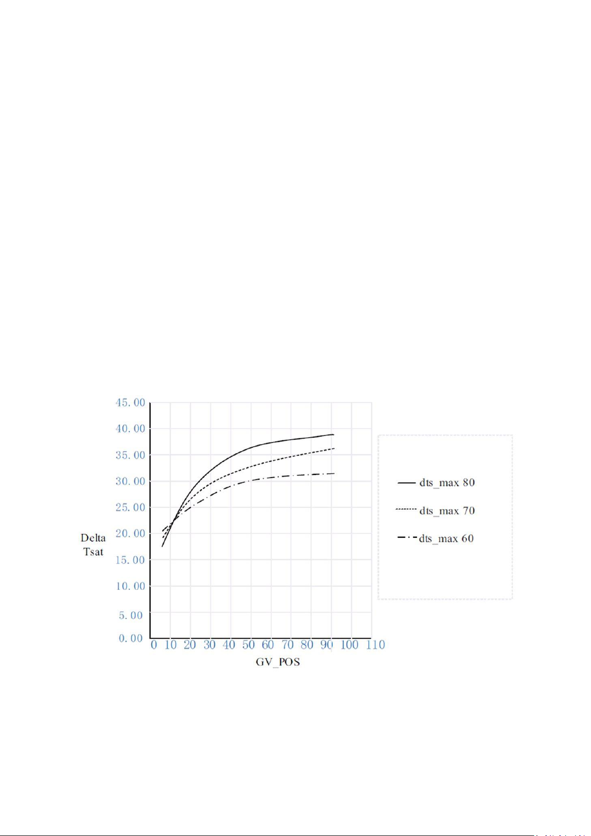
6.7 Surge prevention trouble shooting guide:
1. If chiller surges very frequently, the surge prevention line should be decreased
a. If chiller surges only at full load region, Delta Tsmax should be decreased by 0.28°C for each step until
there is no abnormal surge occurs. See Fig. 48 for the effect of delta Tsmax on surge prevention line.
b. If chiller surges only at low load region, Delta Tsmin should be decreased by 0.28°C for each step until
there is no abnormal surge occurs. See Fig. 49 for the effect of delta Tsmin on surge prevention line.
c. If chiller surges only at medium load region, surge line shape factor should be increased by 0.01 for
each step until there is no abnormal surge occurs. See Fig. 50 for the effect of surge line shape factor on
surge prevention line.
d. If chiller surges at all the regions, delta Tsmax, delta Tsmin and surge line shape factor can be
adjusted at the same time.
2. If chiller no surge but efficiency cannot meet the target, the surge prevention line should be increased
a. If the problem only occurs at full load region, Delta Tsmax should be increased by 0.28°C for each step
until chiller enters real surge. See Fig. 48 for the effect of delta Tsmax on surge prevention line.
b. If the problem only occurs at low load region, Delta Tsmin should be increased by 0.28°C for each step
until chiller enters real surge. See Fig. 49 for the effect of delta Tsmin on surge
prevention line.
c. If the problem only occurs at medium load region, surge line shape factor should be decreased by 0.01
for each step until chiller enters real surge. See Fig. 50 for the effect of surge line shape factor on surge
prevention line.
d. It the problem occur at all the regions, delta Tsmax, delta Tsmin and surge line shape factor can be
adjusted at the same time.
The effect of surge line speed factor on surge prevention line is shown in Fig. 51.
Fig 48 – Effect of surge delta TSmax on Surge prevention
90
Page 91
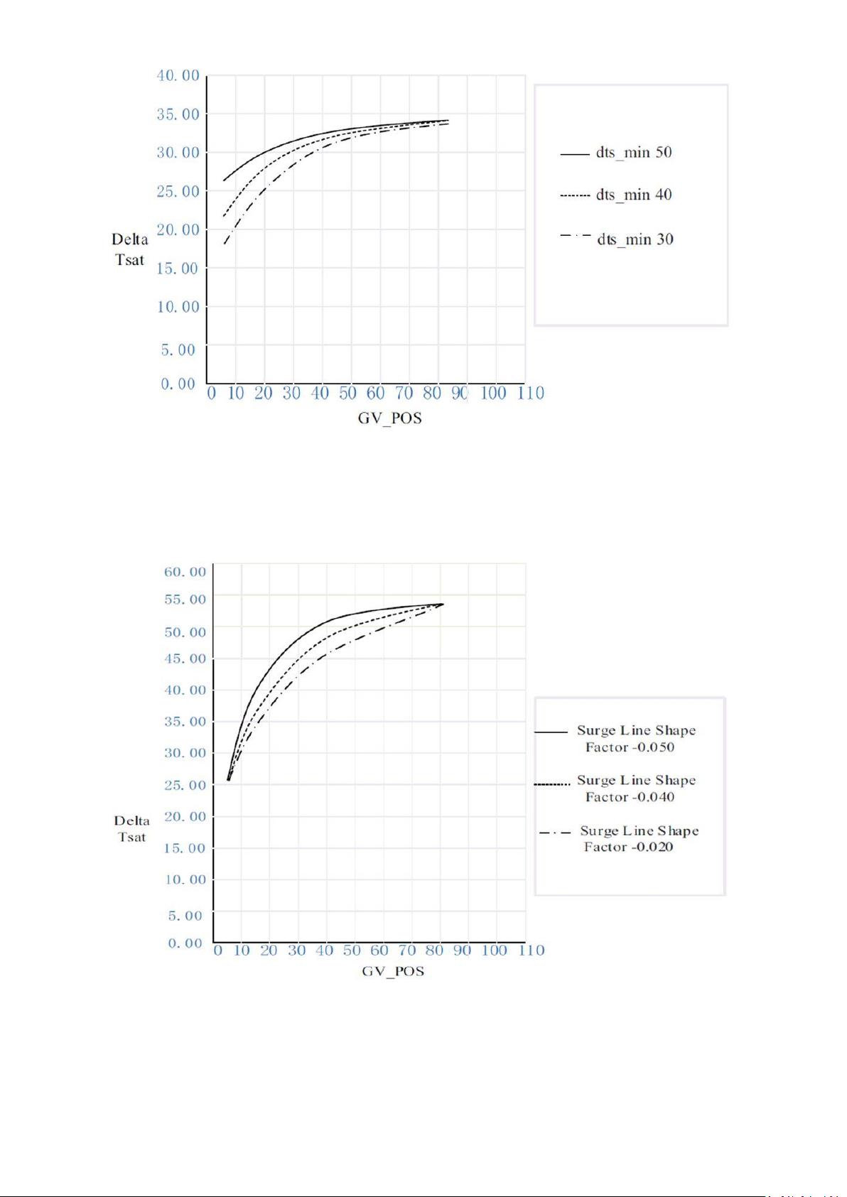
Fig 49 – Effect of surge delta TSmin on Surge prevention
Fig 50 – Effect of surge line shape factor on Surge prevention
91
Page 92
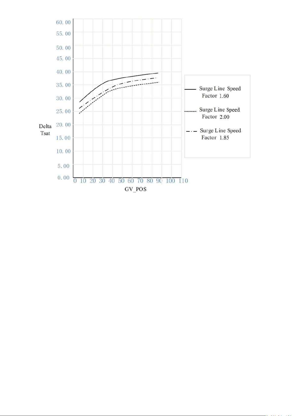
Fig 51 – Effect of surge line speed factor on Surge prevention
7. OPERATING INSTRUCTIONS
7.1 operator duties
1. Become familiar with the chiller and related equipment before operating the chiller.
2. Prepare the system for start-up, start and stop the chiller, and place the system in a shutdown condition.
3. Maintain a log of operating conditions and document any abnormal readings.
4. Inspect the equipment, make routine adjustments, and perform a Control Test. Maintain the proper refrigerant
levels.
5. Protect the system from damage during shutdown periods.
6. Maintain the set point, time schedules, and other PIC5+ functions.
7.2 to start the chiller
1. Start the water pumps, if they are not automatic.
2. Press the Start/Stop icon on the HMI home screen to start the system. If the chiller is in the OCCUPIED mode
and the start timers have expired, the start sequence will start. Follow the procedure described in the StartUp/Shutdown/ Recycle Sequence section.
7.3 Check the running system
After the compressor starts, the operator should monitor the display and observe the parameters for normal
operating conditions:
1. The normal bearing temperature should be about 35°C. Alert will initiate at (40°C and Alarm will be initiated at
50°C.
2. The First Stage and Second Stage Bearing Temperatures can be accessed from the Temperatures menu. If the
bearing temperature is high or in Alarm/Alert state with the refrigerant pump running, stop the chiller and
determine the cause of the high temperature. Do not restart the chiller until corrected.
3. The liquid level sensor on the condenser float chamber should indicate Closed in the INPUT menu.
4. The bearing pressure drop should exceed 90 kPa when the compressor is ON, as seen on the HMI
Transmission Status screen. If not an alert will be generated. Typically the reading will be slightly lower at initial
92
Page 93

start-up. There will be an alarm if compressor is ON and the bearing pressure drop is less than 68.9 kPa diff for 10
seconds.
5. The moisture indicator sight glass on the refrigerant motor cooling line should indicate single phase refrigerant
flow and a dry condition.
6. The condenser pressure and temperature varies with the chiller design conditions. Typically the pressure will
range from -10.3 to 120.6 kPa. with a corresponding temperature range of 15 to 41°C. The condenser entering
water temperature should be controlled below the specified design entering water temperature to save on
compressor kilowatt requirements.
7. Cooler pressure and temperature also will vary with the design conditions. Typical pressure range will be
between 50.8 kPa to -35 kPa, with temperature ranging between 1.1 and 7.2°C.
8. The compressor may operate at full capacity for a short time after the pulldown ramping has ended, even
though the building load is small. The active electrical demand setting can be overridden to limit the compressor
kW, or the pulldown rate can be decreased to avoid a high demand charge for the short period of high demand
operation. Pulldown rate can be based on load rate or temperature rate and is viewed at MAINTENANCE MENU
>> CAPACITY CONTROLS >> RAMP_DEM (Ramping Demand Limit Value). Configuration done in General
Config and rate done in Service Parameters.
9. Both the high and low float chamber have two sight glasses that look into the float chamber to confirm the floats
are not stuck open or closed. When the chiller is operating, the top sight glass is empty and the bottom sight glass
is full.
7.4 To stop the chiller
The occupancy schedule starts and stops the chiller automatically once the time schedule is configured. The unit
can be stopped manually using the HMI by pressing the green Start/Stop icon. The Unit Start/Stop screen is
displayed. Press Confirm Stop. The compressor will then follow the normal shutdown sequence as described in
the Start- Up/Shutdown/Recycle Sequence section. The chiller is now in the OFF control mode.
IMPORTANT: Do not attempt to stop the chiller by opening an isolating knife switch. High intensity arcing may
occur.
If the chiller is stopped by an alarm condition, do not restart the chiller until the problem is diagnosed and
corrected.
7.5 After Limited Shutdown
No special preparations should be necessary. Follow the regular preliminary checks and starting procedures.
7.6 Preparation for Extended Shutdown
If freezing temperatures are likely to occur in the chiller area, drain the chilled water, condenser water, and the
pumpout condenser water circuits to avoid freeze-up. Keep the waterbox drains open. Ensure that chiller is
powered up so purge can automatically remove non-condensables from the low pressure chiller system during the
shutdown. It is recommended not to store the refrigerant in the unit if below freezing temperatures are anticipated
or if the extended shutdown extends past a normal seasonal shutdown. In that case both refrigerant and water
side should be purged with positive pressure of dry nitrogen.
7.7 After Extended Shutdown
Ensure the water system drains are closed. It may be advisable to flush the water circuits to remove any soft rust
that may have formed. This is a good time to brush the tubes and inspect the Schrader fittings on the waterside
flow devices for fouling, if necessary.
Match the actual to the recorded nitrogen pressure prior to the extended shutdown to determine if a leak is
present.
Check the cooler pressure on the HMI panel and compare it to the original holding charge that was left in the
chiller. If (after adjusting for ambient pressure changes) any change in pressure is indicated, check for refrigerant
leaks. See Check Chiller Tightness section.
If charge was removed, recharge the chiller by transferring refrigerant from the pumpout storage tank (if supplied).
Carefully make all regular preliminary and running system checks.
7.8 Cold Weather Operation
When the entering condenser water temperature drops below 12.8 °C, the operator should automatically cycle the
cooling tower fans off to keep the temperature up. Piping may also be arranged to bypass the cooling tower used
to maintain a minimum refrigerant pressure differential during an inverted start condition. The PIC5+ controls have
a low limit tower fan output that can be used to assist in this control with IOB 4 installed.
IMPORTANT: A field-supplied water temperature control system for condenser water should be installed.
The system should be able to maintain the leaving condenser water temperature at design conditions.
93
Page 94
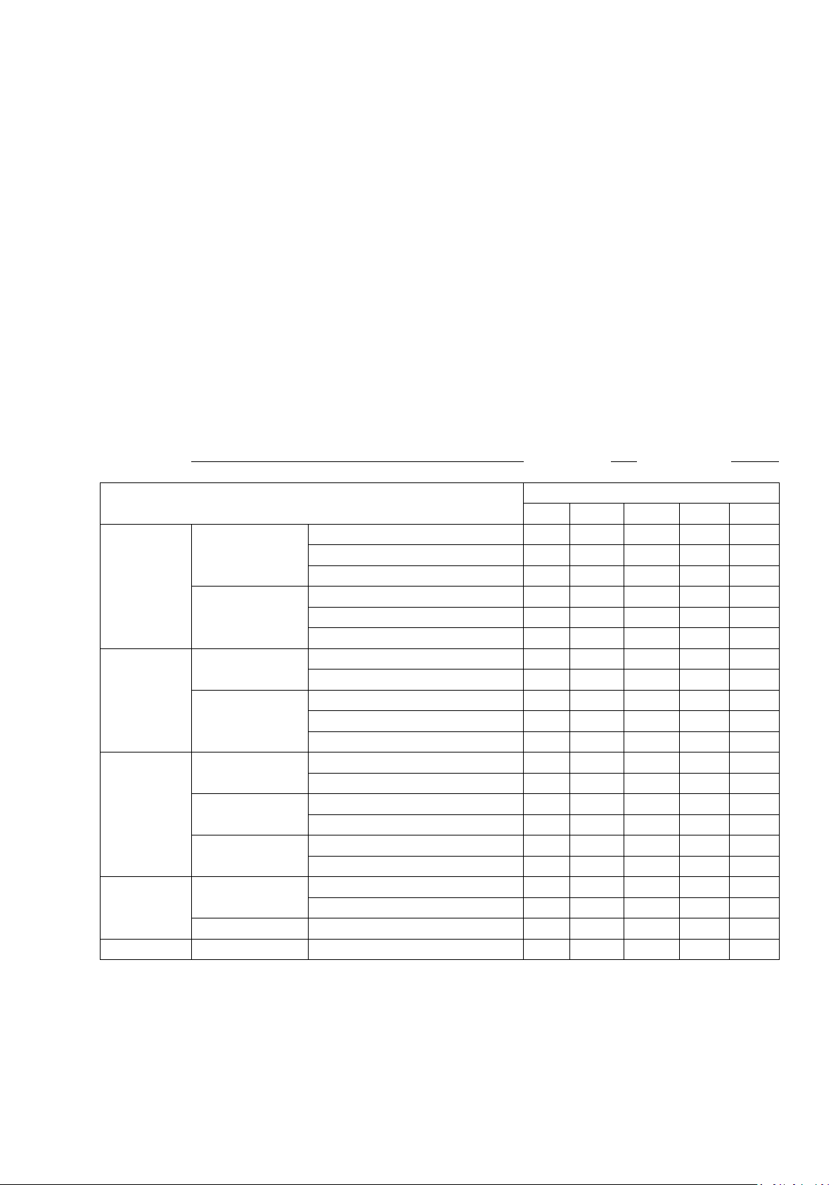
SERVICE AND OPERATION LOG CARRIER 19DV SEMI-HERMETIC CENTRIFUGAL
REFRIGERATION MACHINE
JOB SITE :
MACHINE
MODEL NO.
MACHINE
SERIAL NO
DESCRIPTION
Date
COOLER
REFRIGERANT
PRESSURE SAT
LIQUID TEMP
LEVEL
WATER
FLOW
TEMP IN
TEMP OUT
CONDENSER
REFRIGERANT
PRESSURE
TEMP SAT
WATER
FLOW
TEMP IN
TEMP OUT
COMPRESSOR
CAPACITY
GV1 ACTUAL POS
GV2 ACTUAL POS
BEARINGS
1ST STAGE TEMP
2ND STAGE TEMP
REFRIGERANT
LUBE
BEARING DELTA P
REF PUMP DELTA P
DRIVE TRAIN
MOTOR
RUNNING AMPS
TEMPERATURE
VFD
ACTUAL SPEED
PURGE
RUNTIME
AV DAILY PURGE IN 7 DAYS
7.9 Manual Guide Vane Operation
It is possible to manually operate the guide vanes in order to check control operation or to control the guide vanes
in an emergency. Manual operation is possible by overriding the target guide vane position.
NOTE: Manual control overrides the configured pulldown rate during start-up and permits the guide vanes to open
at a faster rate. Motor current above the electrical demand setting, capacity overrides, and chilled water
temperature below the control point override the manual target and close the guide vanes. For descriptions of
capacity overrides and set points, please refer to separated PIC5+ Control User Manual.
7.10 Service and operation Log
A service and operation log (as shown in Fig. 52), is a convenient checklist for routine inspection and
maintenance and provides a continuous record of chiller performance. It is also an aid when scheduling routine
maintenance and diagnosing chiller problems. Keep a record of the chiller pressures, temperatures, and liquid
levels. Automatic recording of data is possible by using CCN devices such as the Data Collection module and a
Building Supervisor.
Contact a Carrier representative for more information.
Fig 52 – Service and operation log
94
Page 95

7.11 Chiller Idle Requirement
7.11.1 Be idle for a short time:
There is no special requirement, follow the conventional procedure to check and start-up.
7.11.2 Be idle for a long time:
1. Chiller leak prevention
a. If chiller is idle for one month, suggest running purge every week.
b. If chiller is idle for more than one month, suggest charging nitrogen into chiller until chiller pressure is 103 kPa
higher than atmosphere. Before chiller start again, carry out the dehydration process to re-charge refrigerant.
2. Need to run the refrigerant pump to avoid potential corrosion.
3. Chemically treated Water circulation through the condenser and cooler at least once per week for 1-5
minutes (if they are not drained).
4. The purge operation and refrigerant pump operation should be controlled by the PIC 5+ controller to au-
tomatically address these items. The water pumps would need to be manually operated by the customer.
8. PURGE OPERATION SEQUENCE
Refer to fig 53. For the Purge Operation Diagram.
8.1 Purge Operating Modes
Purge system has two operation modes: Auto and Manual.
You can choose it in Configuration Menu->Lab Test Forced->Purge Forced. Select “0” means Auto mode. Select
“1” or “2” means Manual mode, where 1 means purge will be active regardless the purge active condition, “2”
means you can control purge related valves manually.
8.2 Non-condensable Gas Pump Out
When purge tank is full of non-condensable gas, the purge compressor inlet temperature drops to -15 °C, so the
discharge valve and pump out valve open, vacuum pump starts to pump out the non-condensable gas inside
purge tank.
8.3 Carbon Tank and Regeneration Subsystem
If the carbon filter is saturated with refrigerant, the heater can heat carbon filter to about 127 °C. The condenser
valve and cooler valve is closed during this time. Only the pump out valve and regeneration valve is open.
Meanwhile, the vacuum pump will operate at intervals. Regenerated refrigerant is pumped to cooler. After about
120 minutes, the regeneration process stops. However, purge system will wait for another 4 hours to let carbon
filter to cool down before it can operate normally.
95
Page 96
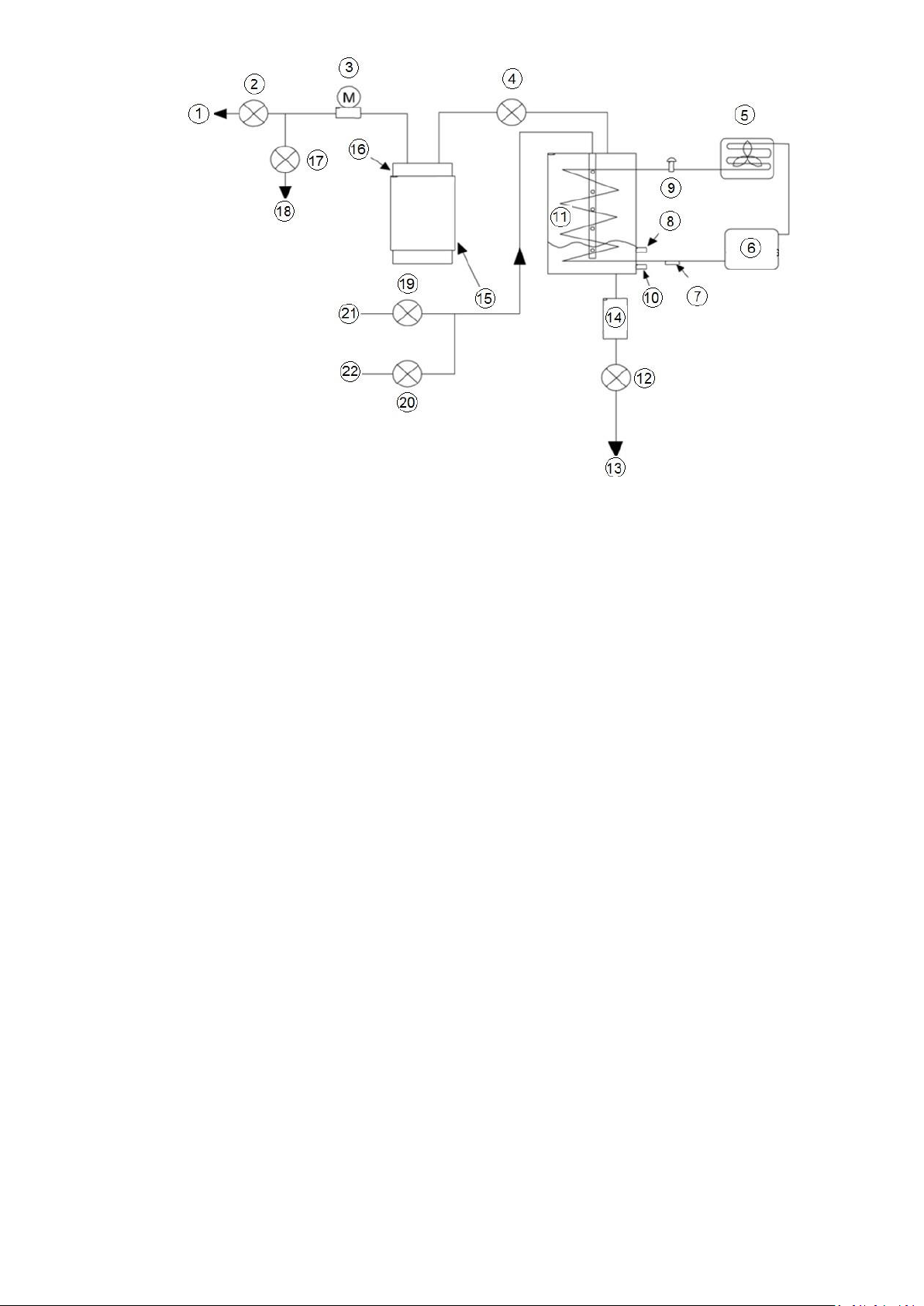
1 : Venting line
2 : Discharge valve
3 : Vacuum pump
4 : Pump out valve
5 : Condenser
6 : Compressor
7 : Suction temperature
8 : High level sensor
9 : Expansion valve
10 : Low level sensor
11 : Purge cooler
12 : Drain filter
13 : Chiller cooler
14 : drain filter
15 : Heater
16 : Carbon filter
17 : Regeneration valve
18 : Chiller cooler
19 : Compressor valve
20 : Condenser valve
21 : Chiller compressor
22 : Chiller condenser
Fig 53 - Purge operation sequence diagram
9. MAINTENANCE
9.1 General maintenance
During the unit operating life the service checks and tests must be carried out in accordance with applicable
national regulations. If there are no similar criteria in local regulations, the information on checks during operation
in annex C of standard EN 378-2 can be used.
External visual checks: Annex A and B of standard EN 378-Corrosion checks: Annex D of standard EN 378-2.
These controls must be carried out:
• After an intervention that is likely to affect the resistance or a change in use or change of high-pressure
refrigerant, or after a shut down of more than two years. Components that do not comply, must be changed. Test
pressures above the respective component design pressure must not be applied (annex B and D).
• After repair or significant modifications or significant system or component extension (annex B)
• After re-installation at another site (annexes A, B and D)
96
Page 97

NOTE 1: High leak rates are not acceptable. The necessary steps must be taken to eliminate any leak detected.
NOTE 2: Fixed refrigerant detectors are not designed to find leaks as they cannot locate the leak.
9.1.1 Soldering and welding
Component, piping and connection soldering and welding operations must be carried out using the correct
procedures and by qualified operators. Pressurised containers must not be subjected to shocks, nor to large
temperature variations during maintenance and repair operations.
9.1.2 Refrigerant properties
The standard refrigerant for the 19DV chiller is HFO R-1233zd(E). At normal atmospheric pressure, HFO R1233zd(E) will boil at 18°C and must, therefore, be kept in pressurized containers or storage tanks.
The refrigerant is practically odorless when mixed with air and is noncombustible at atmospheric pressure. Read
the Material Safety Data Sheet and the latest standard EN 378-2 to learn more about safe handling of this
refrigerant.
DANGER: HFO R-1233zd(E) in heavy concentrations may displace enough oxygen to cause asphyxiation. When
handling this refrigerant, protect the hands and eyes and avoid breathing fumes.
9.1.3 Adding Refrigerant
Follow the procedures described in Trim Refrigerant Charge section.
CAUTION : Always use the compressor pumpdown function in the PUMPDOWN/LOCKOUT feature to turn on the
cooler pump and lock out the compressor when transferring refrigerant. Liquid refrigerant may flash into a gas and
cause possible freeze-up when the chiller pressure is below -53 kPa for HFO R-1233zd(E).
9.1.4 Adjusting the Refrigerant Charge
If the addition or removal of refrigerant is required to improve chiller performance, follow the procedures given
under the Trim Refrigerant Charge section.
9.1.5 Refrigerant Leak Testing
Since parts of the refrigerant system operates in vacuum, non-condensables will enter the cooling systems. The
PIC5+ HMI will issue an alert indicating excessive purge operation. Leaks, which cause frequent purge cycles,
should be repaired without delay. Non-condensable gas in the machine causes higher than normal condenser
pressure, compressor surge at start-up and frequent purge cycles, so locate and repair any leaks as soon as
possible. Before making any necessary repairs to a leak, transfer all refrigerant from the vessel.
9.1.6 Leak Rate
Carrier recommends that leaks totaling less than the above rate but more than a rate of 0.1% of the total charge
per year should be repaired during annual maintenance or whenever the refrigerant is transferred for other service
work.
9.1.7 Test After Service, Repair, or Major Leak
If all the refrigerant has been lost or if the chiller has been opened for service, the chiller or the affected vessels
must be pressure tested and leak tested. Refer to the Leak Test Chiller section to perform a leak test.
WARNING : HFO R-1233zd(E) should not be mixed with air or oxygen and pressurized for leak testing. In general,
this refrigerant should not be present with high concentrations of air or oxygen above atmospheric pressures,
because the mixture can undergo combustion.
9.1.7.1 Testing with refrigerant tracer
Use an environmentally acceptable refrigerant as a tracer for leak test procedures. Use dry nitrogen to raise the
machine pressure to leak testing levels.
9.1.7.2 Testing without refrigerant tracer
Another method of leak testing is to pressurize with nitrogen only and to use a soap bubble solution or an
ultrasonic leak detector to determine if leaks are present.
9.1.7.3 To pressurize with dry nitrogen
NOTE: Pressurizing with dry nitrogen for leak testing should not be done if the full refrigerant charge is in the
vessel because purging the nitrogen is very difficult.
97
Page 98
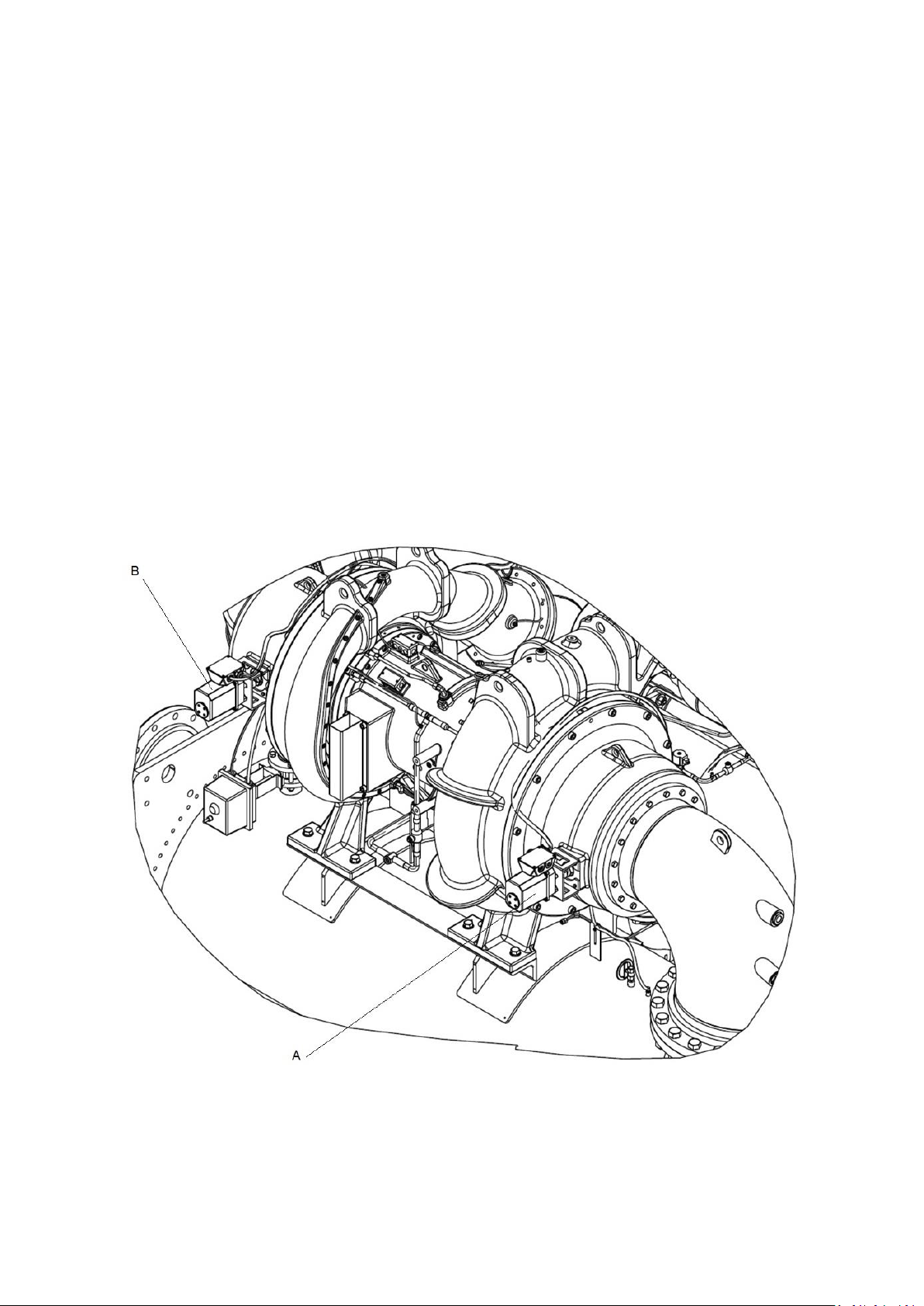
1. Connect a copper tube from the pressure regulator on the cylinder to the refrigerant charging valve. Never apply
full cylinder pressure to the pressurizing line. Follow the listed sequence.
2. Open the charging valve fully.
3. Slowly open the cylinder regulating valve.
4. Observe the pressure gage on the chiller and close the regulating valve when the pressure reaches test level.
Do not exceed design pressure on nameplate.
5. Close the charging valve on the chiller. Remove the copper tube if it is no longer required.
9.1.8 Repair the Leak, Retest, and Apply Standing Vacuum Test
After pressurizing the chiller, test for leaks with an electronic halide leak detector, soap bubble solution, or an
ultrasonic leak detector. Bring the chiller back to atmospheric pressure, repair any leaks found, and retest. A
continuous dry nitrogen purge should be maintained during any leak repairs or when the unit is open to the
atmosphere to reduce the potential for corrosion.
After retesting and finding no leaks, apply a standing vacuum test. Then dehydrate the chiller. Refer to the
Standing Vacuum Test and Chiller Dehydration sections in the Before Initial Start-Up section.
9.1.9 Checking Guide Vanes
During normal shutdown, when the chiller is off, the guide vanes are closed.
Complete the following steps to adjust position if required (see Fig. 55):
1. Remove the set screw in the guide vane coupling.
2. Loosen the hold down bolts on the guide vane actuator.
3. Pull the guide vane actuator away from the suction housing.
4. If required, rotate the guide vane sprocket fully clockwise for first stage and counterclockwise for second stage
and spot-drill the guide vane actuator shaft. Spot-drilling is necessary when the guide vane actuator sprocket set
screws on the guide vane actuator shaft need to be reseated.
(Remember: Spot-drill and tighten the first set screw before spot-drilling for the second set screw.)
A : First stage IGV actuator (IGV1 – M67) Open CCW – Close CW
B : Second stage IGV actuator (IGV2 – M69) Open CW – Close CCW
Fig 54 – IGV actuators position
98
Page 99
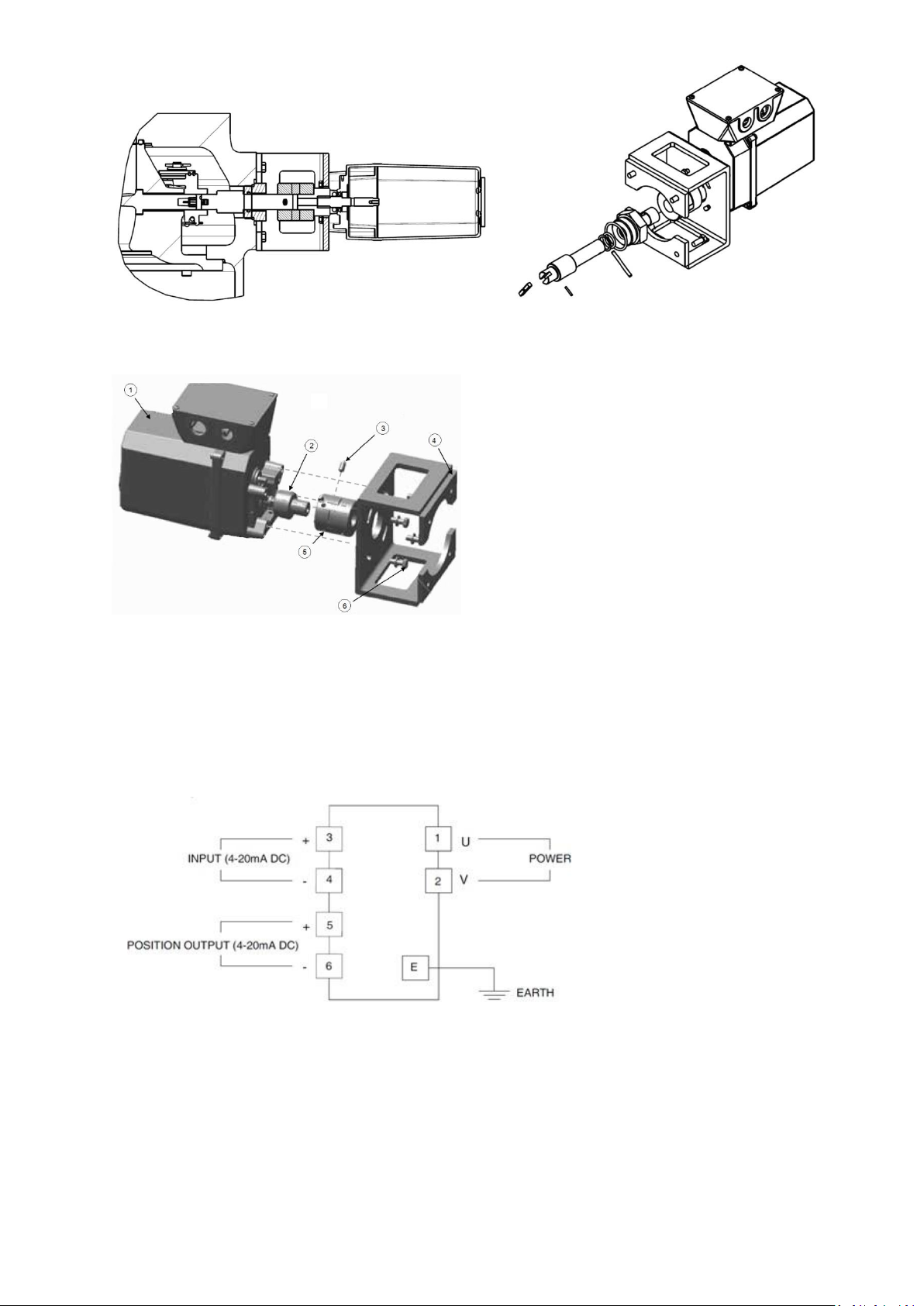
NOTE: For first stage, rotate coupling clockwise to close guide vanes; rotate coupling counterclockwise to open guide vanes.
For second stage, rotate coupling counterclockwise to close guide vanes; rotate coupling clockwise to open guide vanes.
1 : actuator
2 : Connector
3 : Set screw
4 : Bracket
5 : Coupling
6 : Holddown bolts and washers
The guide vane actuator wiring of 19DV is as below :
Fig 55 – IGV actuator details
9.1.10 Trim Refrigerant Charge
If to obtain optimal chiller performance it becomes necessary to adjust the refrigerant charge, operate the chiller at
design load and then add or remove refrigerant slowly until the difference between the leaving chilled water
temperature and the cooler refrigerant temperature reaches design conditions or becomes a minimum.
Do not overcharge. Use cooler sight glass to check the liquid level. The level must be in the middle of sight glass
for correct refrigerant charge in operation. During steady state operation at 80-100% of capacity, the boiling pool
99
Page 100
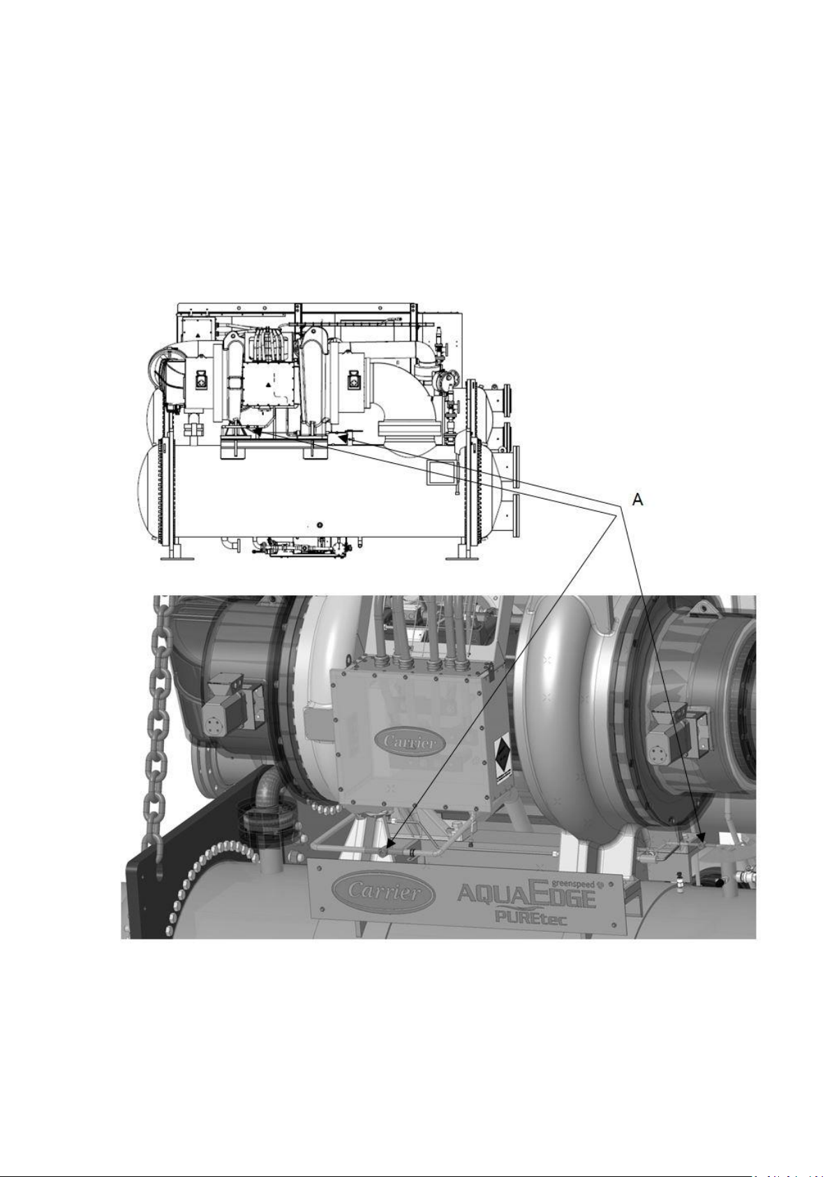
tubes should be covered with liquid refrigerant at all times. There is no benefit to have a refrigerant level higher
than the tubes and capacity will be lost if the tubes are not covered with liquid.
Refrigerant may be added either through a storage tank or directly into the chiller as described in the Charging
Refrigerant section.
9.2 Weekly maintenance
9.2.1 Check the Refrigerant Lubrication System
1. Enter INPUT menu and verify that Liquid Level Switch is closed (if compressor is on).
2. Check moisture indicating sight glass on bearing supply line (Fig. 56) as well as on the motor/VFD liquid
cooling line (located between vessels feeding of the high side float chamber; sight glass is located downstream of
filter drier)
100
 Loading...