

Page 1
PF4MNX
FAN COIL UNITS
SIZES 018 TO 060
Installation Instructions
NOTE: Read the entire instruction manual before starting the
installation.
CAUTION
!
Safety Considerations
Improper installation, adjustment, alteration, service, maintenance, or
use can cause explosion, fire, electrical shock, or other conditions which
may cause death, personal injury or property damage. Consult a
qualified installer, service agency, or your distributor or branch for
information or assistance. The qualified installer or agency must use
factory-authorized kits or accessories when modifying this product.
Refer to the individual instructions packaged with kits or accessories
when installing.
Follow all safety codes. Wear safety glasses, protective clothing and
work gloves. Have a fire extinguisher available. Read these instructions
thoroughly and follow all warnings or cautions included in literature and
attached to the unit. Consult local building codes and the current editions
of the National Electrical Code (NEC) NFPA 70.
In Canada, refer to the current editions of the Canadian Electrical Code
CSA C22.1.
Recognize safety information. This is the safety-alert symbol . When
you see this symbol on the unit and in instruction manuals, be alert to the
potential for personal injury.
Understand the signal words DANGER, WARNING, and CAUTION.
These words are used with the safety-alert symbol. DANGER identifies
the most serious hazards which will result in severe personal injury or
death. WARNING signifies hazards which could result in personal
injury or death. CAUTION is used to identify unsafe practices which
may result in minor personal injury or product and property damage.
NOTE is used to highlight suggestions which will result in enhanced
installation, reliability, or operation.
WARNING
!
PERSONAL INJURY / PROPERTY DAMAGE HAZARD
Failure to follow this warning could result in property damage, personal
injury, or death.
For continued performance, reliability, and safety, the only approved
accessories and replacement parts are those specified by the equipment
manufacturer. The use of non-manufacturer approved parts and
accessories could invalidate the equipment limited warranty and result
in fire risk, equipment malfunction, and failure. Please review
manufacturer’s instructions and replacement part catalogs available
from your equipment supplier.
WARNING
!
ELECTRICAL OPERATION HAZARD
Failure to maintain proper clearances could result in personal injury or
death.
Before installing or servicing unit, always turn off all power to unit.
There may be more than 1 disconnect switch. Turn off accessory heater
power if applicable.
CUT HAZARD
Failure to follow this caution may result in personal injury.
Sheet metal parts may have sharp edges or burrs. Use care and wear
appropriate protective clothing, safety glasses and gloves when
handling parts.
CAUTION
!
HOT TUBE WARNING
Failure to follow this caution could result in personal injury and/or
property damage.
Refrigerant lines can reach or exceed 130 °F (54 °C). Avoid contact
with the vapor header or vapor line, especially in Heating Mode. Do not
service A2L refrigerant fan coils while these components are hot to
avoid risk of ignition source.
Introduction
These R-410A Fan Coils designed for installation flexibility. The units
leave the factory compliant with low leak requirements of less than 2%
cabinet leakage rate at 0.5 inches W.C. and 1.4% cabinet leakage rate at
0.5 inches W.C. when tested in accordance with ASHRAE 193 standard.
All these fan coils use a multi-tap ECM motor for efficiency. The units
have be designed for upflow, downflow (kit required), and horizontal
orientations, including manufactured and mobile home applications.
These units require a field supplied air filter, and are designed
specifically for R-410A refrigerant air conditioners and heat pumps as
shipped. These units are available for systems of 18,000 through 60,000
BTUh nominal cooling capacity. Factory- authorized, field - installed
electric heater packages are available in sizes 5 through 30kW. See
Product Data literature for all available accessory kits.
Heater Packages
NOTE: Some heater sizes may require the removal of two screws which
connect the blower housing to the fan deck (removal will not impact
performance). See (Care and Maintenance on p11) and Fig. 22.
This unit may or may not be equipped with an electric heater package.
For units not equipped with factory-installed heat, a factory-approved,
field-installed, UL listed heater package is available from your
equipment supplier. See unit rating plate for a list of factory-approved
heaters. Heaters that are not factory approved could cause damage which
would not be covered under the equipment warranty. If fan coil contains
a factory-installed heater package, minimum circuit ampacity (MCA)
and maximum fuse/breaker may be different than units with a same size
field-installed accessory heater. The differences is not an error and is due
to calculation difference per UL guidelines.
Page 2
PF4MNX: Installation Instructions
Installation
Check Equipment
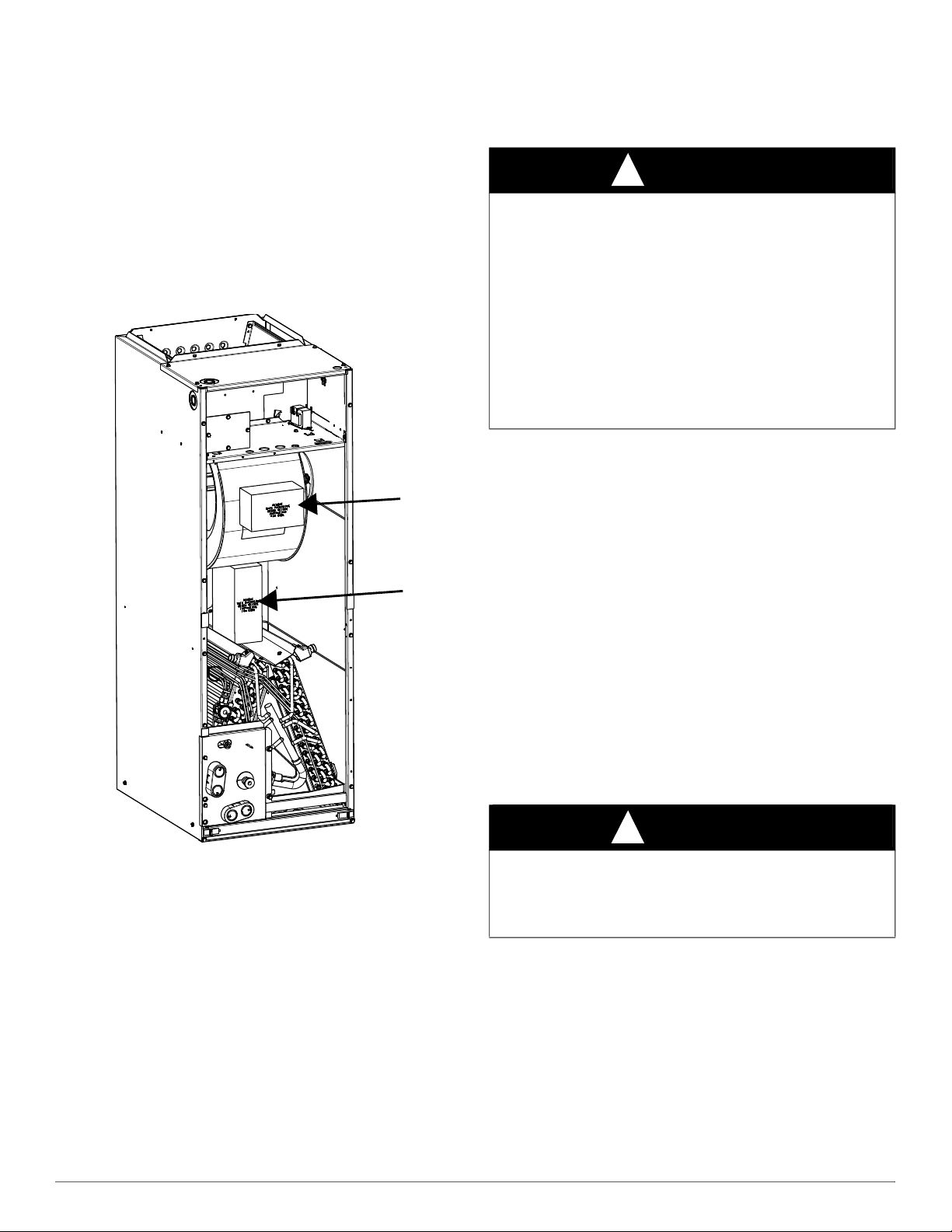
Unpack unit and move to final location. Remove carton taking care not
to damage unit.
NOTE: Shipping block(s) that support the blower housing during transit
will need to be removed (Fig. 1).
NOTE: If the door gasket is damaged or missing, the unit may not meet
the ASHRAE 193 standard for cabinet air leakage. See the Product Data
for this model or contact your supplier to order the gasket kit.
Inspect equipment for damage prior to installation. File claim with
shipping company if shipment is damaged or incomplete. Locate unit
rating plate which contains proper installation information. Check rating
plate to be sure unit matches job specifications.
NOTE:
Downflow Installation
In this application, field conversion of the evaporator is required using
accessory downflow kit along with an accessory base kit. Use fireproof
resilient gasket, 1/8" to ¼" (3 to 6 mm) thick, between duct, unit, and
floor.
CAUTION
!
PRODUCT OR PROPERTY DAMAGE HAZARD
Failure to follow this warning caution may result in product or property
damage.
The conversion of the fan coil to downflow requires special procedures
for the condensate drains on both A-coil and Slope-coil units. The
vertical drains have an overflow hole between the primary and
secondary drain holes. This hole is plugged for all applications except
downflow, and must be used for downflow. During conversion process,
remove plastic cap covering vertical drains only and discard. Remove
plug from overflow hole and discard. At completion of downflow
installation, caulk around vertical pan fitting to door joint to retain low
air leak performance of the unit.
NOTE: To convert units for downflow applications, refer to Installation
Instructions supplied with kit for proper installation. See the Product
Data or contact your supplier for the kit number. Use fireproof resilient
gasket, 1/8" to ¼" (3 to 6 mm) thick, between duct, unit, and floor.
NOTE: A gasket kit is also required for all downflow applications to
maintain low air leak/low sweat performance. See the Product Data or
contact your supplier for the kit number.
Horizontal Installation
Units must not be installed with access panels facing up or down. All
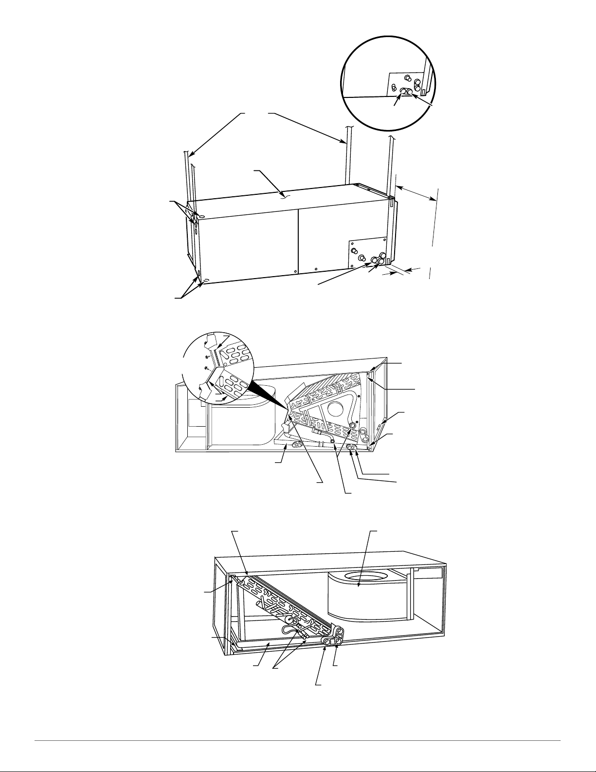
other units are factory built for horizontal left installation (Fig. 3 and
Fig. 4). When suspending unit from ceiling, dimples in casing indicate
suitable location of screws for mounting metal support straps (Fig. 3).
For horizontal applications having high return static and humid return
air, the Water Management Kit may need to be used to assist in water
management. See the Product Data or contact your supplier for the kit
number.
NOTE: Modular units can be disassembled and components moved
separately to installation area for reassembly. This process
accommodates small scuttle holes and limiting entrances to installation
sites (Fig. 7).
Fig. 1 – Remove Shipping Blocks
A221016A
Mount Unit
Unit can stand or lie on floor, or hang from ceiling or wall. Allow space
for wiring, piping, and servicing unit.
IMPORTANT: When unit is installed over a finished ceiling and/or
living area, building codes may require a field-supplied secondary
condensate pan to be installed under the entire unit. Some localities may
allow as an alternative, the running of a separate, secondary condensate
line. Consult local codes for additional restrictions or precautions.
Nuisance sweating may occur if the unit is installed in a high humidity environment with low airflow.
Upflow Installation
If return air is to be ducted through a floor, set unit on floor over opening
and use 1/8" to ¼" (3 to 6 mm) thick fireproof resilient gasket between
duct, unit, and floor.
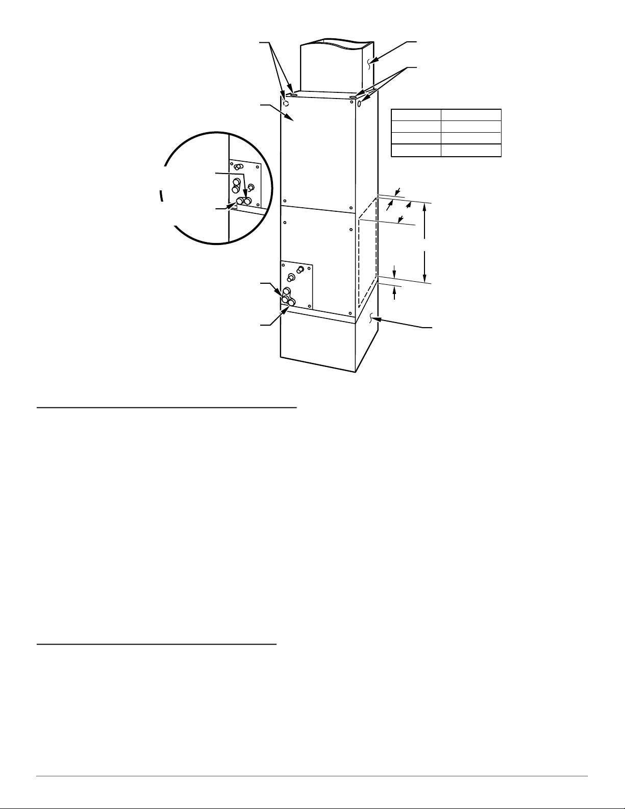
Side return is a field option on slope coil models. Cut opening per
dimensions (Fig. 2). A field-supplied bottom closure is required.
Manufacturer reserves the right to change, at any time, specifications and designs without notice and without obligations.
CAUTION
!
PROPERTY DAMAGE HAZARD
Failure to follow this caution may result in product or property damage.
For optimum condensate drainage performance in horizontal
installations, unit should be leveled along its length and width.
2
Page 3
PF4MNX: Installation Instructions
A COIL
UNITS
POWER ENTRY
OPTIONS
LOW VOLT
ENTRY
OPTIONS
FIELD MODIFIED
SIDE RETURN
LOCATION FOR
SLOPE COIL
UNITS ONLY
FIELD SUPPLIED
RETURN PLENUM
UPFLOW/DOWNFLOW
SECONDARY DRAIN
UPFLOW/DOWNFLOW
PRIMARY DRAIN
UNIT
018, 024
025 - 030
A
12" (305 mm)
17" (432 mm)
A
1.5" (38 mm)
2.5"
(64 mm)
19" (483 mm)
FIELD SUPPLIED
SUPPLY DUCT
UPFLOW/DOWNFLOW
SECONDARY DRAIN
UPFLOW/DOWNFLOW
PRIMARY DRAIN
036 19" (483 mm)
018 - 048 21" (533 mm) FRONT SERVICE
060 - 060 24" (610mm) CLEARANCE
Horizontal Right Conversion of Units with Slope Coils
NOTE: A gasket kit is required for horizontal slope coil conversion to
maintain low air leak/low sweat performance. See the Product Data or
contact your supplier for the kit number.
1. Remove blower and coil access panels and fitting panel (Fig. 6).
2. Remove coil mounting screw securing coil assembly to right side casing flange.
3. Remove coil assembly.
4. Lay fan coil on its right side and reinstall coil assembly with condensate pan down (Fig. 5).
5. Attach coil to casing flange using previously removed coil mounting screw.
6. Make sure pan cap in fitting door is properly seated on fitting door to retain low air leak rating of the unit.
7. Add gaskets from kit.
8. Align holes with tubing connections and condensate pan connections. Reinstall access panels and fitting panel.
9. Make sure liquid and suction tube grommets are in place to prevent air leaks and cabinet sweating. Install grommets after brazing.
Horizontal Right Conversion of Units with A-Coils
1. Remove blower and coil access panels (Fig. 6).
2. Remove metal clip securing fitting panel to condensate pan. Remove fitting panel.
3. Remove 2 snap-in clips securing A-coil in unit.
4. Slide coil and pan assembly out of unit.
5. Remove horizontal drain pan support bracket from coil support rail on left side of unit and reinstall on coil support rail on right side of unit (Fig. 8).
6. Convert air seal assembly for horizontal right.
Manufacturer reserves the right to change, at any time, specifications and designs without notice and without obligations.
Fig. 2 – Slope Coil Unit in Upflow Application
a. Remove air seal assembly from coil by removing 4 screws
(Fig. 6).
b. Remove air splitter (B) from coil seal assembly by removing 3
screws (Fig. 7 inset).
c. Remove filler plate (A) and install air splitter (B) in place of filler
plate.
d. Install filler plate (A) as shown in horizontal right application.
e. Remove condensate troughs (C) and install on opposite tube
sheets.
f. Install hose onto plastic spout.
7. Install horizontal pan on right side of coil assembly.
8. Slide coil assembly into casing. Be sure coil bracket on each corner of vertical pan engages coil support rails.
9. Reinstall 2 snap-in clips to correctly position and secure coil assembly in unit. Be sure clip with large offsets is used on right side of unit to secure horizontal pan.
10. Remove two oval fitting caps from left side of the coil, access panel, and fitting panel.
11. Remove insulation knockouts on right side of coil access panel.
12. Remove 2 oval coil access panel plugs and reinstall into holes on left side of coil access panel and fitting panel.
13. Install condensate pan fitting caps (from Step 10) in right side of coil door making sure that cap snaps and seats cleanly on back side of the coil door. Make sure no insulation interferes with seating of cap.
14. Reinstall access and fitting panels, aligning holes with tubing connections and condensate pan connections. Be sure to reinstall metal clip between fitting panel and vertical condensate pan.
15. Make sure liquid and suction tube grommets are in place to prevent air leaks and cabinet sweating.
3
A07565
Page 4
PF4MNX: Installation Instructions
UNIT
FIELD
SUPPLIED
HANGING
STRAPS
LOW VOLT
ENTRY
OPTIONS
POWER
ENTRY OPTIONS
SECONDARY
DRAIN
018-048 21" (533 mm)
060-060 24" (610 mm)
FRONT SERVICE
CLEARANCE
(FULL FACE
OF UNIT)
SECONDARY
DRAIN
A-COIL
HORIZONTAL LEFT
PRIMARY
DRAIN
PRIMARY
DRAIN
1.75" (44 mm)
FILTER ACCESS
CLEARANCE
A
B
C
FACTORY SHIPPED
HORIZONTAL LEFT
APPLICATION
AIR SEAL
ASSEMBLY
HORIZONTAL
DRAIN PAN
REFRIGERANT
CONNECTIONS
SECONDARY DRAIN
HORIZONTAL LEFT
PRIMARY DRAIN
HORIZONTAL LEFT
COIL
SUPPORT
RAIL
COIL
BRACKET
DRAIN PAN
SUPPORT
BRACKET
COIL
BRACKET
COIL MOUNTING
SCREW
BLOWER
ASSEMBLY
REFRIGERANT
CONNECTIONS
SECONDARY DRAIN
PRIMARY DRAIN
DRAINPAN
SLOPE COIL
SKI
COIL
SUPPORT
RAIL
Fig. 3 – Slope Coil in Horizontal Left Application (Factory Configuration)
Fig. 4 – A-Coil in Horizontal Left Application (Factory Configuration)
A07566
A00072A
Fig. 5 – Conversion for Horizontal Right Applications - Slope Coil
Manufacturer reserves the right to change, at any time, specifications and designs without notice and without obligations.
4
A03001
Page 5

PF4MNX: Installation Instructions
COIL
SUPPORT
RAIL
COIL
BRACKET
DRAIN PAN
SUPPORT
BRACKET
COIL
SUPPORT
RAIL
COIL
BRACKET
HORIZONTAL
DRAIN PAN
PRIMARY DRAIN
HORIZONTAL RIGHT
SECONDARY DRAIN
HORIZONTAL RIGHT
REFRIGERANT
CONNECTIONS
AIR SEAL
ASSEMBLY
A
B
C
HORIZONTAL
RIGHT
APPLICATION
2 SCREWS
2 SCREWS
REAR CORNER
BRACKET
BLOWER BOX
COIL BOX
2 SCREWS
DRAIN PAN
SUPPORT BRACKET
DOWN FLOW
BASE KIT (KFACB)
UNIT AGAINST WALL
.125" (3mm)
MOUNTING BRACKET
(TYPICAL BOTH SIDES)
SECURE FAN COIL TO STRUCTURE
UNIT AWAY FROM WALL
PIPE STRAP
(TYPICAL BOTH SIDES)
OR
SECURE UNIT TO FLOOR
ANGLE BRACKET OR PIPE STRAP
4” (102mm) MAX
4” (102mm) MAX
Manufactured and Mobile Home Housing Applications
1. Secure the fan coil to the structure using field-supplied hardware.
2. Allow a minimum of 24" (610 mm) clearance from access panels.
3. Recommended method of securing for typical applications:
Fig. 6 – Conversion for Horizontal Right Applications - A-Coil
a. If fan coil is away from wall, attach pipe strap to top of fan coil
using no. 10 self-tapping screws. Angle strap down and away
from back of fan coil, remove all slack, and fasten to wall stud of
structure using 5/16" lag screws. Typical both sides of fan coil.
b. If fan coil is against wall, secure fan coil to wall stud using 1/8"
(3 mm) thick right-angle brackets. Attach brackets to fan coil
using no. 10 self-tapping screws and to wall stud using 5/16" lag
screws (Fig. 9).
Fig. 8 – Drain Pan Support Bracket
A00071A
A07571
Fig. 7 – Removal of Brackets on Modular Unit
A95293
Manufacturer reserves the right to change, at any time, specifications and designs without notice and without obligations.
Fig. 9 – Mobile Home or Manufactured Housing Applications
5
A07567
Page 6

PF4MNX: Installation Instructions
R
G
W
Y
THERMOSTAT
RED
GRY
WHT
BLU
VIO
BRN
WHT
R
G
W
2
W
3
E
C
FAN COIL
(CONTROL)
C
Y
AIR COND.
Air Ducts
Connect supply-air duct over the outside of ¾" (19 mm) flanges
provided on supply-air opening. Secure duct to flange, using proper
fasteners for type of duct used, and seal duct-to-unit joint. If return-air
flanges are required, install factory-authorized accessory kit.
Use flexible connectors between ductwork and unit to prevent
transmission of vibration. When electric heater is installed, use
heat-resistant material for flexible connector between ductwork and unit
at discharge connection. Ductwork passing through unconditioned space
must be insulated and covered with vapor barrier.
Units equipped with 20-30kW electric heaters require a 1" (25 mm)
clearance to combustible materials for the first 36" (914 mm) of supply
duct. All 18,000 BTU units equipped with 8 or 10 kW electric heaters
require a 1" (25.4 mm) clearance to combustible materials for the first
12" of supply duct.
Ductwork Acoustical Treatment
Metal duct systems that do not have a 90 degree elbow and 10 feet of
main duct before first branch takeoff may require internal acoustical
insulation lining. As an alternative, fibrous ductwork may be used if
constructed and installed in accordance with the latest edition of
SMACNA construction standard on fibrous glass ducts. Both acoustical
lining and fibrous ductwork shall comply with National Fire Protection
Association as tested by UL Standard 181 for Class 1 air ducts.
Electrical Connections
Units from the factory protect the low voltage circuit with a 3A
automotive type fuse in-line on the wire harness and Does Not contain a
circuit board. Motor speeds and time delay function are built into the
motor. See (Minimum CFM and Motor Speed Selection on p7) for
clarification.
When a factory-approved accessory control package has been installed,
check all factory wiring per unit wiring diagram and inspect factory
wiring connections to be sure none were loosened during transit or
installation. If a different control package is required, see unit rating
plate.
Before proceeding with electrical connections, make certain that supply
voltage, frequency, phase, and ampacity are as specified on the unit
rating plate. See unit wiring label for proper field high- and low-voltage
wiring. Make all electrical connections in accordance with the NEC and
any local codes or ordinances that may apply. Use copper wire only.
The unit must have a separate branch electric circuit with a
field-supplied disconnect switch located within sight from, and readily
accessible from, the unit.
On units with a factory-installed disconnect with pull-out removed,
service and maintenance can be safely performed on only the load side
of the control package.
WARNING
!
ELECTRICAL SHOCK OR UNIT DAMAGE HAZARD
Failure to follow this warning could result in personal injury, death,
and/or unit damage.
If a disconnect switch is to be mounted on unit, select a location where
drill and fasteners will not contact electrical or refrigeration
components.
WARNING
!
ELECTRICAL SHOCK HAZARD
Failure to follow this warning could result in personal injury or death.
Field wires on the line side of the disconnect found in the fan coil unit
remain live, even when the pull-out is removed. Service and
maintenance to incoming wiring cannot be performed until the main
disconnect switch (remote to the unit) is turned off.
Line Voltage Connections
If unit contains an accessory electric heater, remove and discard power
plug from fan coil and connect male plug from heater to female plug
from unit wiring harness. (See Electric Heater Installation Instructions.)
For units without electric heat:
1. Connect 208/230V power leads from field disconnect to yellow and black stripped leads.
2. Connect ground wire to unit ground lug.
NOTE: Units installed without electric heat should have a field-supplied
sheet metal block-off plate covering the heater opening. This will reduce
air leakage and formation of exterior condensation.
24V Control System
Connection To Unit
Wire low voltage in accordance with wiring label on the blower (Fig. 10
thru Fig. 13). Use #18 AWG color-coded, insulated (35° C minimum)
wire to make the low-voltage connections between the thermostat, the
unit, and the outdoor equipment. If the thermostat is located more than
100' (30 m) from the unit (as measured along the low-voltage wire), use
#16 AWG color-coded, insulated (35° C minimum) wire. All wiring
must be NEC Class 1 and must be separated from incoming power leads.
Refer to outdoor unit wiring instructions for any additional wiring
procedure recommendations.
PERSONAL OR EQUIPMENT DAMAGE HAZARD.
Failure to follow this warning could result in personal injury, death,
and/or unit damage.
Provide training to installation personnel to follow national and local
electrical codes.
WARNING
!
Manufacturer reserves the right to change, at any time, specifications and designs without notice and without obligations.
Fig. 10 – Wiring Layout Air Conditioning Unit
(Cooling Only)
6
A94058
Page 7

PF4MNX: Installation Instructions
R
G
W
Y
THERMOSTAT
R
G
W
2
W
3
E
C
FAN COIL
(CONTROL)
C
Y
AIR COND.
RED
GRY
WHT
WHT
BLU
VIO
BRN
R
G
C
E
L
O
Y
THERMOSTAT
R
R
C
O
Y
G
C
W
2
W
2
W
2
W
3
E
FAN COIL
(CONTROL)
HEAT PUMP
(CONTROL)
A94060
RED
GRY
BRN
WHT
BLU
VIO
R
E
W2
R
C
THERMOSTAT
FAN COIL
(CONTROL)
HEAT PUMP
(CONTROL)
G
C
W2
E
L
G
C
R
O
Y
ODTS
O
Y
W3
W2
230
C
208
BRN
RED
YEL
BLK
SECONDARY
PRIMARY
Transformer Information
The transformer is factory wired for 230V operation. For 208V
applications, disconnect the black wire from the 230V terminal on
transformer and connect it to the 208V terminal (Fig. 14).
Fig. 11 – Wiring Layout Air Conditioning Unit
(Cooling and 1-Stage Heat)
Fig. 12 – Wiring Layout Heat Pump Unit
(Cooling and 2-Stage Heat with No Outdoor Thermostat)
A94059
A94060
Fig. 14 – Transformer Connections
A05182
Heater Staging
If electric heat staging is required, a multi-stage heating room thermostat
is required. Consult your equipment supplier for a suitable thermostat.
Manufactured Housing
In manufactured housing applications, the Code of Federal Regulations,
Title 24, Chapter XX, Part 3280.714 requires that supplemental electric
heat be locked out at outdoor temperatures above 40° F (4° C), except
for a heat pump defrost cycle. See Fig. 13 for typical low voltage wiring
with outdoor thermostat.
Ground Connections
NOTE: Use UL listed conduit and conduit connectors for connecting
supply wire(s) to unit to obtain proper grounding. Grounding may also
be accomplished by using grounding lugs provided in control box.
WARNING
!
ELECTRICAL SHOCK HAZARD
Failure to establish uninterrupted or unbroken ground could result in
personal injury and/or death.
According to NEC, NFPA 70, and local codes, the cabinet must have an
uninterrupted or unbroken ground to minimize personal injury if an
electrical fault should occur. The ground may consist of electrical wire
or metal conduit when installed in accordance with existing electrical
codes. If conduit connection uses reducing washers, a separate ground
wire must be used.
Fig. 13 – Wiring Layout Heat Pump Unit
(Cooling and 2-Stage Heat for Manufactured Housing)
Manufacturer reserves the right to change, at any time, specifications and designs without notice and without obligations.
Minimum CFM and Motor Speed Selection
The fan speed selection is done at the motor connector. Units with or
without electric heaters require a minimum CFM. Refer to the unit
wiring label to ensure that the fan speed selected is not lower than the
minimum fan speed indicated.
A03088
7
Page 8

PF4MNX: Installation Instructions
1 2 3 4 5
Speed Taps may be located on motor,
or on plug close to motor.
CLGN
1 2 3 4 5
CAUTION
!
PRODUCT DAMAGE HAZARD
Failure to follow this caution may result in product or property damage.
A brazing shield MUST be used when tubing sets are being brazed to
the unit connections to prevent damage to the unit surface and
condensate pan fitting caps.
Units have sweat suction and liquid tube connections. Make suction tube
connection first.
1. Cut tubing to correct length.
2. Insert tube into sweat connection on unit until it bottoms.
3. Braze connection using silver bearing or non-silver bearing brazing materials. Do not use solder (materials which melt below 800° F / 427° C). Consult local code requirements.
4. Evacuate coil and tubing system to 500 microns using a deep vacuum method.
CAUTION
!
PRODUCT DAMAGE HAZARD
Failure to follow this caution may result in product or property damage.
Wrap a wet cloth around rear of fitting to prevent damage to TXV and
factory-made joints.
Fig. 15 – Motor Speed Selection
Table 1 – Fan Speed Selection
Tap 1
Tap 2
Tap 3
Tap 4
Tap 5
† electric heat airflow is same CFM as Tap 3, except 0 sec off delay
‡ high static applications, see airflow tables for max airflow
To change motor speeds disconnect the BLUE fan lead from motor
connector terminal #2 (factory default position) and move to desired
speed-tap; 1, 2, 3, or 5.
Speed-taps 1, 2, and 3 have a 90 second blower off time delay
pre-programmed into the motor. Speed-tap 4 is used for electric heat
only (with 0 second blower time delay) and the WHITE wire should
remain on tap 4. Speed-tap 5 is used for high static applications, but has
a 0 second blower time delay pre-programmed into the motor. See
Airflow Performance tables for actual CFM. Se Fig. 15 for motor speed
selection location.
NOTE: In low static applications, lower motor speed tap should be used
to reduce possibility of water being blown off coil.
Low 90 sec off delay
Medium 90 sec off delay
High 90 sec off delay
Electric heat † 0 sec off delay
Max ‡ 0 sec off delay
Refrigerant Tubing Connection and Evacuation
Use accessory tubing package or field-supplied tubing of refrigerant
grade. Suction tube must be insulated. Do not use damaged, dirty, or
contaminated tubing because it may plug refrigerant flow-control
device. ALWAYS evacuate the coil and field-supplied tubing to 500
microns before opening outdoor unit service valves.
A11048
Refrigerant Flow-Control Device
The 018-060 size units come equipped with a R-410A refrigerant
mechanical TXV. When tightening nuts on a TXV, do not exceed
20 ft-lbs.
Always use outdoor units designed to match indoor fan coil applications.
CAUTION
!
PRODUCT OPERATION HAZARD
Failure to follow this caution may result in improper product operation.
If using a TXV in conjunction with a single-phase reciprocating
compressor, a compressor start capacitor and relay are required.
Consult outdoor unit pre-sale literature for start assist kit part number.
Disassembly
WARNING
!
PERSONAL INJURY HAZARD
Failure to follow this warning could result in personal injury.
Remove refrigerant charge from system and ensure there is no pressure
before servicing the TXV.
NOTE: For Item #1 (Fig. 16): Use an adjustable wrench with a backup
adjustable wrench to loosen the brass nut (TXV outlet). Then use both
wrenches to loosen Item # 2 (TXV inlet).
1. Use an adjustable wrench with a backup adjustable wrench to loosen Item # 3 (TXV equalizer line).
2. For Item #4 - Cut the wire tie and remove the black insulation. Remove the band from around the TXV bulb.
3. Cut the wire tie that holds the TXV equalizer line and bulb from the aluminum vapor header tube.
4. Remove 2 screws from the TXV bracket. Remove the TXV from the coil unit.
Manufacturer reserves the right to change, at any time, specifications and designs without notice and without obligations.
8
Page 9

PF4MNX: Installation Instructions
1
2
3
4
2” MIN
(51 mm)
UNIT
2” MIN
(51 mm)
DO NOT USE SHALLOW RUNNING TRAPS!
Assembly
1. Mount the TXV bracket and TXV with the 2 screws removed during disassembly.
2. Connect Items #1 and #2 (TXV outlet and inlet respectively) and use an adjustable wrench with a backup wrench to tighten each nut. Tighten to between 10 and 20 ft-lbs.
3. Connect Item #3 and use an adjustable wrench with a backup adjustable wrench to tighten the flare nut. Tighten to approximately 12 ft-lbs.
4. Item # 4 - Reconnect the TXV bulb with a clamp and reinstall insulation around the TXV bulb and vapor tube.
NOTE: When connecting condensate drain lines, avoid blocking filter
access panel, thus preventing filter removal. After connection, prime
both primary and secondary condensate traps.
CAUTION
!
PRODUCT DAMAGE HAZARD
Failure to follow this caution may result in product or property damage.
Use only full size P-traps in the condensate line (Fig. 17). Shallow
running traps are inadequate and DO NOT allow proper condensate
drainage (Fig. 18).
CAUTION
!
UNIT OR PROPERTY DAMAGE HAZARD
Failure to follow this warning caution may result in product or property
damage.
The conversion of the fan coil to downflow requires special procedures
for the condensate drains on both A-coil and Slope-coil units. The
vertical drains have an overflow hole between the primary and
secondary drain holes. This hole is plugged for all applications except
downflow, and must be used for downflow. During conversion process,
remove plastic cap covering vertical drains only and discard. Remove
plug from overflow hole and discard. At completion of downflow
installation, caulk around vertical pan fitting to door joint to retain low
air leak performance of the unit.
Fig. 16 – Mechanical TXV Removal
CAUTION
!
UNIT DAMAGE HAZARD
Failure to follow this Caution may result in unit damage.
Failure to place insulation between copper tubes and aluminum parts
will lead to galvanic corrosion, which will result in a refrigerant leak in
the future.
5. Use a wire tie to mount the 1/8" TXV equalizer and bulb tubes to
the vapor header tube. Make sure that there is insulation between
the aluminum vapor tube and copper tube.
6. Leak test the TXV fittings, then evacuate and charge the system to the required subcooling per the outdoor unit rating plate.
Condensate Drains
To connect drains, the cap openings must be removed. Use a knife to
start the opening near the tab and using pliers, pull the tab to remove the
disk. Clean the edge of the opening if necessary and install the
condensate line. Finally caulk around the lines where they exit the fitting
to retain the low leak rating of the unit.
Units are equipped with primary and secondary ¾" FPT drain
connections. For proper condensate line installations see Fig. 2 thru
Fig. 6. To prevent property damage and achieve optimum drainage
performance, BOTH primary and secondary drain lines should be
installed and include properly-sized condensate traps (Fig. 17 and
Fig. 19). Factory-approved condensate traps are available. It is
recommended that PVC fittings be used on the plastic condensate pan.
Finger-tighten plus 1-1/2 turns. Do not over-tighten. Use pipe dope.
NOTE: Do not use CPVC in field drain lines due to potential reaction
with POE oil.
Manufacturer reserves the right to change, at any time, specifications and designs without notice and without obligations.
A221106
Fig. 17 – Recommended Condensate Trap
Fig. 18 – Insufficient Condensate Trap
NOTE: If unit is located in or above a living space where damage may
result from condensate overflow, a field-supplied, external condensate
pan should be installed underneath the entire unit, and a secondary
condensate line (with appropriate trap) should be run from the unit into
the pan. Any condensate in this external condensate pan should be
drained to a noticeable place. As an alternative to using an external
condensate pan, some localities may allow the use of a separate ¾"
(19 mm) condensate line (with appropriate trap) to a place where the
condensate will be noticeable. The owner of the structure must be
informed that when condensate flows from the secondary drain or
external condensate pan, the unit requires servicing or water damage will
occur.
9
A03002
A03013
Page 10

PF4MNX: Installation Instructions
FILTER
ACCESS
PANEL
SECONDARY DRAIN WITH
APPROPRIATE TRAP REQUIRED
(USE FACTORY KIT OR
FIELD-SUPPLIED TRAP)
PRIMARY TRAP REQUIRED
(USE FACTORY KIT OR
FIELD-SUPPLIED TRAP OF
SUFFICIENT DEPTH.
STANDARD P-TRAPS ARE
NOT SUFFICIENT. SEE
FIGURE OF RECOMMENDED
CONDENSATE TRAP)
R
G
C
E
L
O
Y
THERMOSTAT
R
R
C
O
Y
G
C
W
2
W
2
W
2
W
3
E
FAN COIL
(CONTROL)
HEAT PUMP
(CONTROL)
RED
GRY
BRN
WHT
WHT
BLU
VIO
HUMIDISTAT
RELAY
FAN HUMIDIFIER
115V
M
R
G
W
Y
THERMOSTAT
R
G
W
2
W
3
E
C
FAN COIL
(CONTROL)
C
Y
AIR COND.
HUMIDISTAT
FAN HUMIDIFIER
115V
RED
GRY
WHT
WHT
BLU
VIO
BRN
M
Install traps in the condensate lines as close to the coil as possible.
(Fig. 19). Make sure that the outlet of each trap is below its connection
to the condensate pan to prevent condensate from overflowing the drain
pan. Prime all traps, test for leaks, and insulate traps if located above a
living area. Condensate drain lines should be pitched downward at a
minimum slope of 1" (25 mm) for every 10' (3 m) of length. Consult
local codes for additional restrictions or precautions.
Accessories
Humidifier
Connect the humidifier and humidistat to the fan coil unit as shown in
Fig. 20 and Fig. 21. The cooling lockout relay is optional.
Sequence of Operation
Continuous Fan
Thermostat closes the R to G connection. G energizes the fan relay on
the PCB which completes the circuit to the indoor blower motor. When
G is de-energized, there is a 90-second delay before the relay opens.
Fig. 19 – Condensate Drain
Fig. 20 – Wiring Layout of Humidifier to Heat Pump
Manufacturer reserves the right to change, at any time, specifications and designs without notice and without obligations.
A03003
A95294
Fig. 21 – Wiring Layout of Humidifier to Fan Coil
with Electric Heat
Cooling Mode
Thermostat energizes R to G, R to Y, and R to O (heat pump only). G
energizes the fan relay on the PCB which completes the circuit to the
indoor blower motor. When G is de-energized, there is a 90-second delay
before the fan relay opens.
Heat Pump Heating with Auxiliary Electric Heat
Thermostat energizes R to G, R to Y, and R to W connections. G
energizes the fan relay on the PCB which completes the circuit to the
indoor blower motor. W energizes the electric heat relay(s) which
completes the circuit to the heater element(s). When W is de-energized,
the electric heat relay(s) open, turning off the heater elements. When G
is de-energized there is a 90-second delay before the fan relay opens.
Electric Heat or Emergency Heat Mode
Thermostat closes R to W connection. W energizes the electric heat
relay(s) which completes the circuit to the heater element(s). Blower
motor is energized through the normally-closed contacts on the fan relay.
When W is de-energized, the electric heat relay(s) opens.
Start-up Procedures
Refer to outdoor unit Installation Instructions for system start-up
instructions and refrigerant charging method details.
CAUTION
!
PRODUCT DAMAGE HAZARD
Failure to follow this caution may result in poor unit performance
and/or product damage.
Never operate unit without a filter. Factory authorized filter kits may be
used when locating the filter inside the unit. For those applications
where access to an internal filter is impractical, a field-supplied filter
must be installed in the return air duct system.
10
A95295
Page 11

PF4MNX: Installation Instructions
Care and Maintenance
To continue high performance and minimize possible equipment failure,
it is essential that periodic maintenance be performed on this equipment.
Consult your local dealer as to the proper frequency of maintenance
contract.
The ability to properly perform maintenance on this equipment requires
certain mechanical skills and tools. If you do not possess these, contact
your dealer for maintenance. The only consumer service recommended
or required is filter replacement or cleaning on a monthly basis.
NOTE: Servicing the blower assembly requires the removal of two
screws that attach the blower housing to the fan deck. It is not necessary
to reinstall of these screws after service.
Fig. 22 – Shipping Screws
Table 2 – Electric Heater Static Pressure Drop (in. wc)
Sizes 018 - 036 Sizes 042 - 060
Heater Elements kW
0 0 +.02 0 0 +.04
1 3, 5 +.01 1 3, 5 +.03
2 8, 10 0 2 8, 10 +.02
3 9, 15 -.02 3 9, 15 0
4 20 -.04 4 20 -.02
External Static
Pressure Correction
Heater Elements kW
6 18, 24, 30 -.10
A221041A
External Static
Pressure Correction
Manufacturer reserves the right to change, at any time, specifications and designs without notice and without obligations.
11
Page 12

PF4MNX: Installation Instructions
Ton
(Size)
Blower
Speed
Tap 5 754 737 717 694 668 641 605 572 528 481
Tap 4 695 678 655 628 600 573 551 520 479 421
1-1/2
(018)
Tap 3 695 678 655 628 600 573 551 520 479 421
Tap 2 643 620 591 557 534 506 477 439 408 378
Tap 1 487 448 428 394 358 325 281 NA NA NA
Tap 5 1021 1003 964 925 876 838 797 761 726 689
Tap 4 936 907 873 805 779 732 696 661 626 591
2
(024)
Tap 3 936 907 873 805 779 732 696 661 626 591
Tap 2 846 831 792 739 702 651 609 548 536 491
Tap 1 746 697 629 567 521 477 446 389 364 326
Tap 5 1247 1215 1188 1154 1122 1083 1053 1017 971 915
Tap 4 1133 1114 1082 1044 1009 968 924 873 835 785
2-1/2
(030)
Tap 3 1133 1114 1082 1044 1009 968 924 873 835 785
Tap 2 1040 997 961 929 883 828 782 725 708 667
Tap 1 896 862 805 740 689 648 597 NA NA NA
Tap 5 1433 1404 1363 1328 1282 1251 1201 1145 1095 1021
Tap 4 1304 1277 1256 1230 1207 1168 1122 1080 1073 983
3
(036)
Tap 3 1304 1277 1256 1230 1207 1168 1122 1080 1073 983
Tap 2 1183 1148 1124 1094 1051 1005 955 901 846 783
Tap 1 1020 995 958 921 881 840 791 735 693 649
Tap 5 1571 1551 1508 1473 1439 1407 1372 1317 1253 1189
Tap 4 1517 1493 1458 1425 1392 1358 1328 1295 1253 1193
3-1/2
(042)
Tap 3 1517 1493 1458 1425 1392 1358 1328 1295 1253 1193
Tap 2 1369 1339 1299 1263 1226 1188 1155 1112 1068 1012
Tap 1 1260 1231 1172 1143 1077 1041 995 949 896 867
Tap 5 1896 1853 1821 1795 1760 1737 1702 1670 1665 1619
Tap 4 1711 1673 1643 1607 1570 1549 1509 1490 1446 1411
4
(048)
Tap 3 1711 1673 1643 1607 1570 1549 1509 1490 1446 1411
Tap 2 1547 1504 1466 1416 1388 1369 1324 1290 1239 1200
Tap 1 1397 1347 1312 1269 1232 1172 1135 1086 1038 989
Tap 5 2109 2067 2043 1996 1967 1928 1899 1848 1812 1766
Tap 4 2109 2067 2043 1996 1967 1928 1899 1848 1812 1766
5
(060)
Tap 3 2109 2067 2043 1996 1967 1928 1899 1848
Tap 2 1901 1868 1825 1785 1737 1710 1662 1620 1584 1521
Tap 1 1583 1557 1499 1451 1392 1358 1313 1259 1194 1138
Table 3 – Airflow Performance (CFM) Wet
External Static (in. wc)
0.1 0.2 0.3 0.4 0.5 0.6 0.7 0.8 0.9 1.0
1812 1766
NOTES:
1. Airflow based upon dry coil at 230V with factory-approved filter and electric heater (2 element heater sizes 018 through 036, 3 element heater sizes 042 through 060).
2. To avoid potential for condensate blowing out of drain pan prior to making drain trap:
Return static pressure must be less than 0.40 in. wc. Horizontal applications of 042 - 060 sizes must have supply static greater than 0.20 in. wc.
Airflow above 400 cfm/ton on 048-060 size could result in condensate blowing off coil or splashing out of drain pan.
Manufacturer reserves the right to change, at any time, specifications and designs without notice and without obligations.
12
Page 13

PF4MNX: Installation Instructions
Ton
(Size)
Blower
Speed
Tap 5 762 741 721 698 672 656 635 577 547 509
Tap 4 695 679 655 628 600 580 559 534 505 452
1-1/2
(018)
Tap 3 695 679 655 628 600 580 559 534 505 452
Tap 2 634 615 585 547 522 506 475 444 407 371
Tap 1 498 470 434 390 356 300 272 NA NA NA
Tap 5 1046 1013 978 958 925 877 830 752 722 687
Tap 4 992 950 916 869 812 763 705 660 611 585
2
(024)
Tap 3 992 950 916 869 812 763 705 660 611 585
Tap 2 900 862 814 769 709 644 594 548 507 451
Tap 1 762 723 651 599 531 471 428 385 345 319
Tap 5 1277 1244 1226 1193 1169 1122 1094 1058 1014 969
Tap 4 1179 1142 1114 1070 1039 998 937 915 867 825
2-1/2
(030)
Tap 3 1179 1142 1114 1070 1039 998 937 915 867 825
Tap 2 1066 1030 997 960 916 863 795 746 703 674
Tap 1 923 878 832 784 723 658 616 563 NA NA
Tap 5 1489 1463 1428 1388 1345 1305 1262 1213 1160 1093
Tap 4 1357 1337 1310 1283 1249 1212 1165 1114 1064 1014
3
(036)
Tap 3 1357 1337 1310 1283 1249 1212 1165 1114 1064 1014
Tap 2 1211 1190 1162 1132 1100 1066 1016 959 905 838
Tap 1 1059 1038 1004 967 925 887 843 791 747 681
Tap 5 1647 1620 1583 1548 1505 1464 1424 1379 1319 1250
Tap 4 1569 1539 1506 1476 1442 1404 1370 1336 1299 1219
3-1/2
(042)
Tap 3 1569 1539 1506 1476 1442 1404 1370 1336 1299 1219
Tap 2 1393 1355 1329 1288 1248 1223 1180 1138 1091 1037
Tap 1 1265 1234 1195 1154 1111 1062 1022 964 914 865
Tap 5 1956 1917 1887 1855 1831 1798 1763 1743 1707 1683
Tap 4 1773 1743 1704 1667 1634 1612 1571 1536 1500 1464
4
(048)
Tap 3 1773 1743 1704 1667 1634 1612 1571 1536 1500 1464
Tap 2 1566 1524 1483 1451 1414 1376 1340 1303 1266 1217
Tap 1 1413 1373 1328 1283 1246 1204 1168 1120 1075 1012
Tap 5 2148 2123 2084 2048 2002 1974 1939 1891 1893 1812
Tap 4 2148 2123 2084 2048 2002 1974 1939 1891 1893 1812
5
(060)
Tap 3 2148 2123 2084 2048 2002 1974 1939 1891
Tap 2 1955 1913 1868 1833 1796 1757 1711 1654 1632 1570
Tap 1 1646 1590 1527 1496 1442 1373 1315 1294 1221 1164
Table 4 – Airflow Performance (CFM) Dry
External Static (in. wc)
0.1 0.2 0.3 0.4 0.5 0.6 0.7 0.8 0.9 1.0
1893 1812
NOTES:
1.Airflow based upon dry coil at 230V with factory-approved filter and electric heater (2 element heater sizes 018 through 036, 3 element heater sizes 042 through 060).
2. To avoid potential for condensate blowing out of drain pan prior to making drain trap:
Return static pressure must be less than 0.40 in. wc. Horizontal applications of 042 - 060 sizes must have supply static greater than 0.20 in. wc.
Airflow above 400 cfm/ton on 048-060 size could result in condensate blowing off coil or splashing out of drain pan.
© 2022 Carrier. All rights reserved.
Edition Date: 11/22
Catalog No: IM-PF4MNX-02
A Carrier Company
Manufacturer reserves the right to change, at any time, specifications and designs without notice and without obligations.
13
Replaces: IM-PF4MNX-01
 Loading...