

Page 1
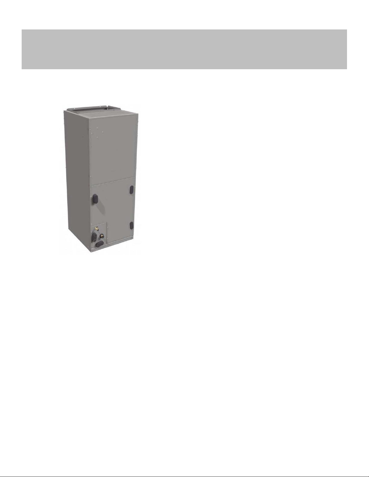
PF4MN
Base Series Fan Coil
Sizes 18 - 60
Product Data
A12580
AIR HANDLER TECHNOLOGY AT ITS FINEST
The PF4MN fan coil has the proven technology of Payne fan coil units
with R-410A refrigerant as well as vertical and horizontal applications.
The design features contoured condensate pans with rugged drain
connections, ensuring that little water is left in the unit at the end of the
cooling duty cycle. The lack of standing condensate and corrosion free
pans improves IAQ and product life, features homeowners appreciate.
Standard features include grooved tubing and louvered fins. Coil
circuiting has also been updated to make the most of all Payne heat
pumps and air conditioners. Units come with solid state fan controls,
1-inch (25mm) thick insulation with R-value of 4.2, multi-speed motors,
and fully-wettable coils. Units can accommodate factory- and/or
field-installed heaters from 3 to 30 kW.
Assembled at the factory compliant with low leak requirements of less
than 2% cabinet leakage rate at 0.5 inches W.C. and 1.4% cabinet
leakage rate at 0.5 inches W.C. when tested in accordance with
ASHRAE 193 standard.
The PF4MN fan coil design is loaded with popular features. These fan
coils utilize the latest in electronic commutation motor (ECM)
technology through the use of high efficiency, multi-tap ECM motors
allowing reliable air delivery with increased static pressure. It comes in a
pre-painted (taupe metallic) galvanized steel casing and a
factory-supplied power plug for ease of installation. The unit is shipped
with a R-410A refrigerant TXV (sizes 18–60).
STANDARD FEATURES
• Multi-tap ECM (electronic commutating motor) motors – all sizes
• Integrated motor controls, with 90-sec off TDR function, have
replaced integrated circuit board.
• Five available speed tags to meet a wide range of applications
• Large, grooved tube, louvered fin coils
• Efficient, quiet, time-tested blower housings and diffusers
• Sturdy, drainable condensate pans
• Cabinet construction features innovations designed to prevent cabinet
sweating.
• Tested for condensate disposal in much tougher conditions than Air
Conditioning and Refrigeration Institute requirements.
• Super-thick R-4.2 insulation with vapor barrier
• Pre-painted galvanized steel cabinet (taupe metallic)
• Design meets stringent regulations for cabinet air leakage of less than
2% when tested at 0.5 inches W.C., and cabinet air leakage less than
1.4% at 0.5 inches W.C. when tested in accordance with ASHRAE
193 standard.
• Installation-flexible, multipoise units
• Horizontal hanging provisions on cabinet
• No tools required to access filter.
• Newly improved filter rack area filter door insulation added for
improved air seal.
• Factory-installed heater packages available on select models
(5 through 15 kW).
• 3 through 30 kW accessory heaters - field installed
• Factory-supplied power plug
• Easy plug-in provisions for heater installation.
• Entry options for high and low voltage wiring hook-up.
• Leak-preventing sweat connections
• Thermostatic expansion valve, TXV, on all coils
• Designed for manufactured housing applications.
Page 2
PF4MN: Product Data
Use of the AHRI Certified
TM Mark indicates a
manufacturer’s
participation in the
program For verification
of certification for individual
products, go to
www.ahridirectory.org.
MODEL NUMBER NOMENCLATURE
1 2 3 4 5 6 7 8 9 10 11 12
P F 4 M N X A 1 8 L 0 0
Product Type L = Aluminum Coil
Fan Coil, Multipoise with R-410A
Electrical
N - 208/230v, 1 ph, 60 Hz Capacity
18 = 18,000
Cabinet/Expansion Device 24 = 24,000
X = Singular, TXV 30 = 30,000
36 = 36,000
42 = 42,000
48 = 48,000
60 = 60,000
00 = Heater Size
A200437
Manufacturer reserves the right to change, at any time, specifications and designs without notice and without obligations.
2
Page 3
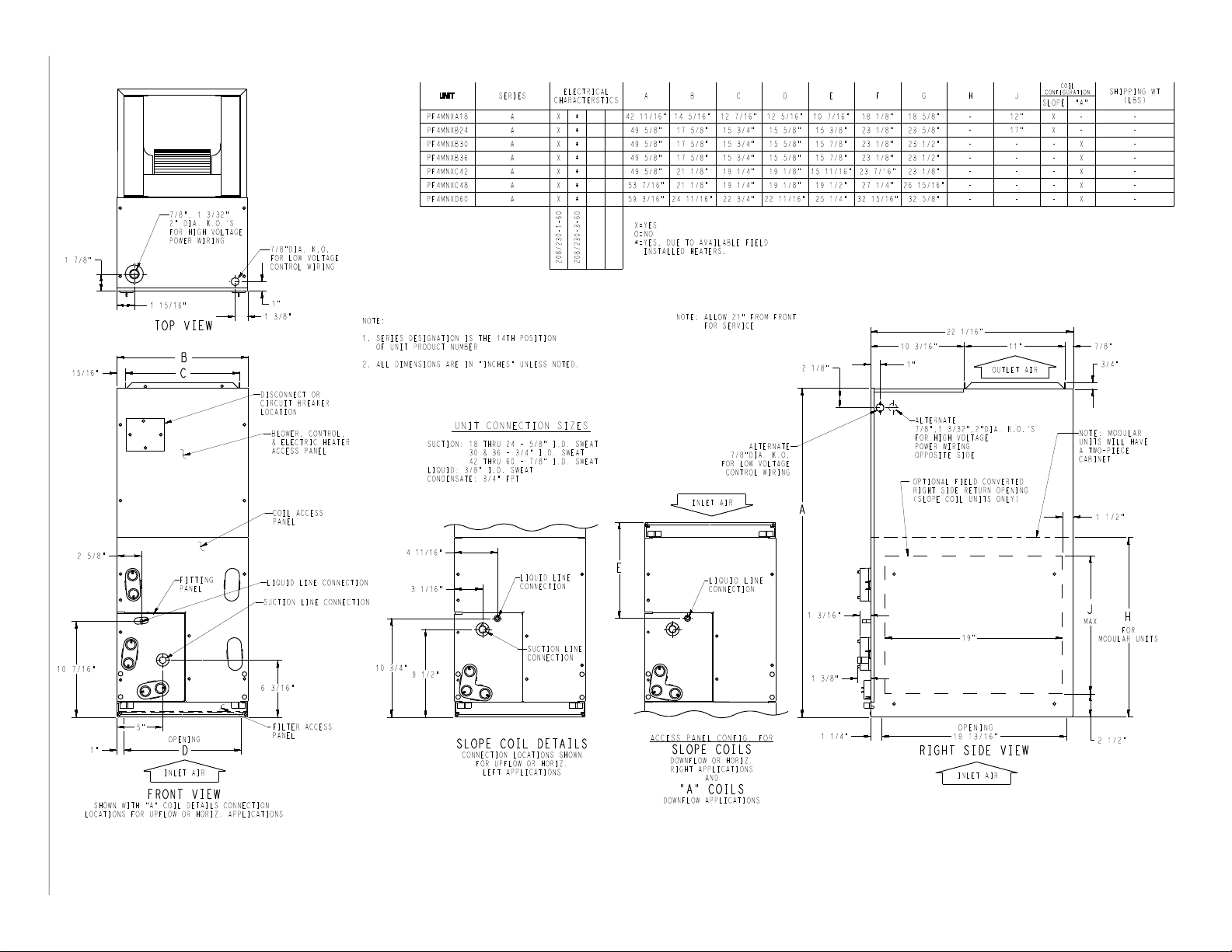
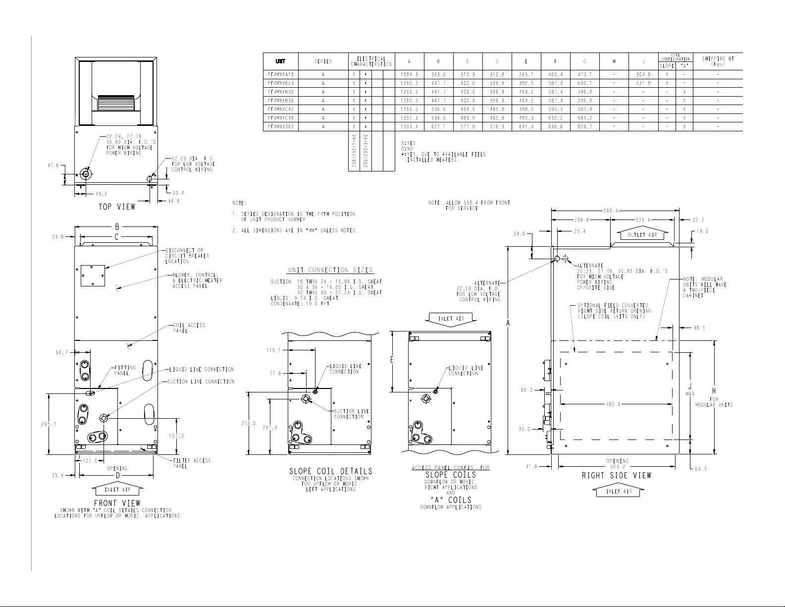
DIMENSIONS
Manufacturer reserves the right to change, at any time, specifications and designs without notice and without obligations.
3
PF4MN: Product Data
Fig. 1 – PF4 - English (sheet 1)
A221207
Page 4
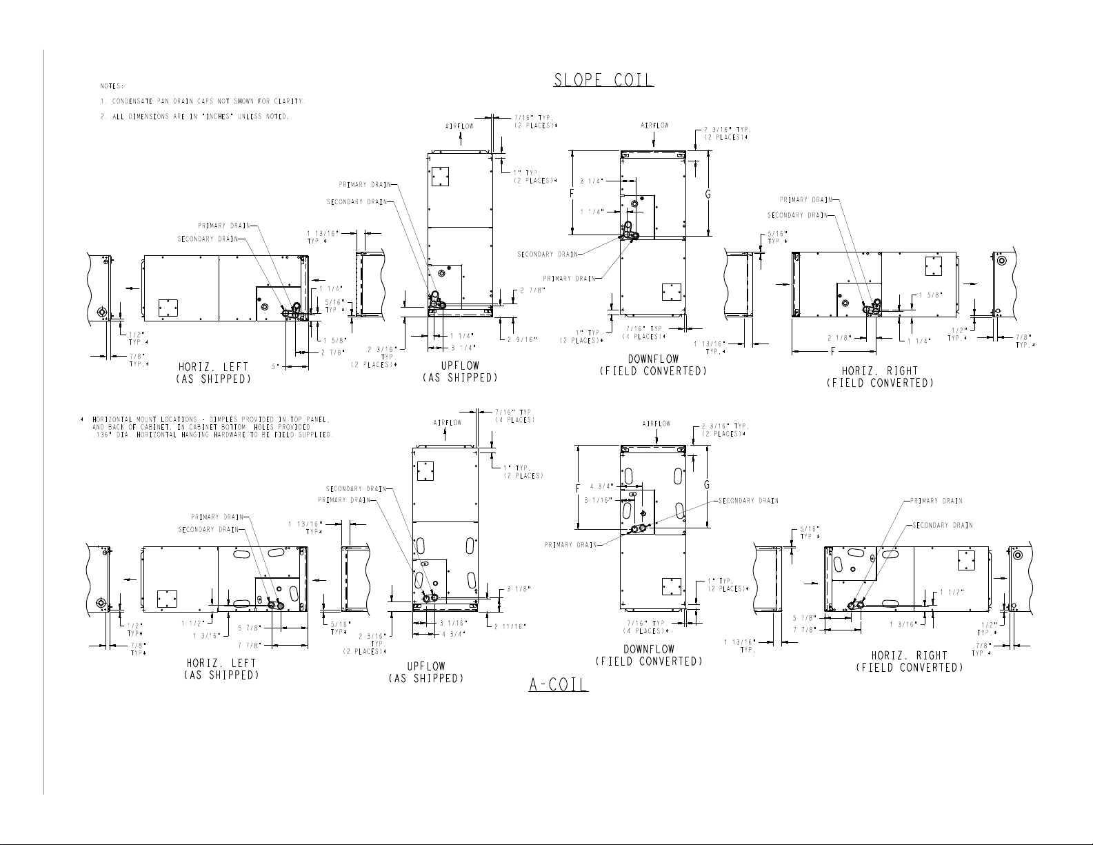
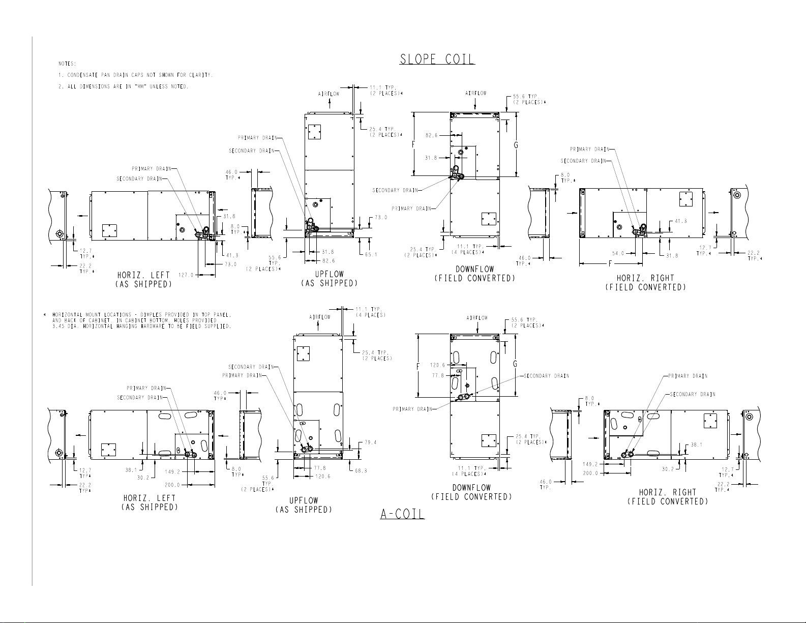
DIMENSIONS (cont.)
Manufacturer reserves the right to change, at any time, specifications and designs without notice and without obligations.
4
PF4MN: Product Data
Fig. 2 – PF4- English (sheet 2)
A221208
Page 5
DIMENSIONS (cont.)
Manufacturer reserves the right to change, at any time, specifications and designs without notice and without obligations.
5
PF4MN: Product Data
Fig. 3 – PF4 - Metric (sheet 1)
A221209
Page 6
DIMENSIONS (cont.)
Manufacturer reserves the right to change, at any time, specifications and designs without notice and without obligations.
6
PF4MN: Product Data
Fig. 4 – PF4 - Metric (sheet 2)
A221210
Page 7

PF4MN: Product Data
Table 1 – PHYSICAL DATA
UNIT SIZE
18 18,000
24 24,000
30 30,000
36 36,000
42 42,000
48 48,000
60 60,000
NOMINAL COOLING
CAPACITY (Btuh)
Height Width Depth
42-11/16 in.
(1084mm)
49-5/8 in.
(1260mm)
49-5/8 in.
(1260mm)
49-5/8 in.
(1260mm)
49-5/8 in.
(1260mm)
53-7/16 in.
(1357mm)
59-3/16 in.
(1503mm)
DIMENSIONS – IN (mm)
14-5/16 in.
(364mm)
17-5/8 in.
(448mm)
17-5/8 in.
(448mm)
17-5/8 in.
(448mm)
21-1/8 in.
(537mm)
21-1/8 in.
(537mm)
24-11/16 in.
(627mm)
22-1/16 in.
(560mm)
22-1/16 in.
(560mm)
22-1/16 in.
(560mm)
22-1/16 in.
(560mm)
22-1/16 in.
(560mm)
22-1/16 in.
(560mm)
22-1/16 in.
(560mm)
SHIPPING WEIGHT
LB (KG)
120
(54.4)
131
(59.4)
148
(67.1)
148
(67.1)
166
(75.3)
182
(82.5)
210
(95.2)
Table 2 – SPECIFICATIONS
SIZE 18 24 30 36 42 48 60
EVAPORATOR COIL
Face Area (sq. ft) 2.23 2.97 3.96 4.45 5.93 7.42
Configuration Slope A
Metering Device
FILTER SIZE (W x L)
BLOWER ASSEMBLY
Motor Type (ECM) Multi-tap ECM
Motor HP 1/3 1/3 1/2 1/2 1/2 3/4 3/4
CFM 525 700 875 1050 1225 1400 1750
R-410A TXV
13-in x 20-in
(330.2 x 508 mm)
16-in x 20-in
(406.4 x 508 mm)
20-in x 20-in
(508 x 508 mm)
23-in x 20-in
(584.2 x 508.0 mm)
Manufacturer reserves the right to change, at any time, specifications and designs without notice and without obligations.
7
Page 8

PF4MN: Product Data
PERFORMANCE DATA
Ton
(Size)
1-1/2
(18)
2
(24)
2-1/2
(30)
3
(36)
3-1/2
(42)
4
(48)
5
(60)
Blower
Speed
Tap 5 754 737 717 694 668 641 605 572 528 481
Tap 4 695 678 655 628 600 573 551 520 479 421
Tap 3 695 678 655 628 600 573 551 520 479 421
Tap 2 643 620 591 557 534 506 477 439 408 378
Tap 1 487 448 428 394 358 325 281 NA NA NA
Tap 5 1021 1003 964 925 876 838 797 761 726 689
Tap 4 936 907 873 805 779 732 696 661 626 591
Tap 3 936 907 873 805 779 732 696 661 626 591
Tap 2 846 831 792 739 702 651 609 548 536 491
Tap 1 746 697 629 567 521 477 446 389 364 326
Tap 5 1247 1215 1188 1154 1122 1083 1053 1017 971 915
Tap 4 1133 1114 1082 1044 1009 968 924 873 835 785
Tap 3 1133 1114 1082 1044 1009 968 924 873 835 785
Tap 2 1040 997 961 929 883 828 782 725 708 667
Tap 1 896 862 805 740 689 648 597 NA NA NA
Tap 5 1433 1404 1363 1328 1282 1251 1201 1145 1095 1021
Tap 4 1304 1277 1256 1230 1207 1168 1122 1080 1073 983
Tap 3 1304 1277 1256 1230 1207 1168 1122 1080 1073 983
Tap 2 1183 1148 1124 1094 1051 1005 955 901 846 783
Tap 1 1020 995 958 921 881 840 791 735 693 649
Tap 5 1571 1551 1508 1473 1439 1407 1372 1317 1253 1189
Tap 4 1517 1493 1458 1425 1392 1358 1328 1295 1253 1193
Tap 3 1517 1493 1458 1425 1392 1358 1328 1295 1253 1193
Tap 2 1369 1339 1299 1263 1226 1188 1155 1112 1068 1012
Tap 1 1260 1231 1172 1143 1077 1041 995 949 896 867
Tap 5 1896 1853 1821 1795 1760 1737 1702 1670 1665 1619
Tap 4 1711 1673 1643 1607 1570 1549 1509 1490 1446 1411
Tap 3 1711 1673 1643 1607 1570 1549 1509 1490 1446 1411
Tap 2 1547 1504 1466 1416 1388 1369 1324 1290 1239 1200
Tap 1 1397 1347 1312 1269 1232 1172 1135 1086 1038 989
Tap 5 2109 2067 2043 1996 1967 1928 1899 1848 1812 1766
Tap 4 2109 2067 2043 1996 1967 1928 1899 1848 1812 1766
Tap 3 2109 2067 2043 1996 1967
Tap 2 1901 1868 1825 1785 1737 1710 1662 1620 1584 1521
Tap 1 1583 1557 1499 1451 1392 1358 1313 1259 1194 1138
Table 3 – Airflow Performance (CFM) Wet
External Static (in. wc)
0.1 0.2 0.3 0.4 0.5 0.6 0.7 0.8 0.9 1.0
1928 1899 1848 1812 1766
NOTES:
1. Airflow based upon dry coil at 230V with factory-approved filter and electric heater (2 element heater sizes 018 through 036, 3 element heater sizes 042 through 060).
2. To avoid potential for condensate blowing out of drain pan prior to making drain trap:
Return static pressure must be less than 0.40 in. wc. Horizontal applications of 042 - 060 sizes must have supply static greater than 0.20 in. wc.
Airflow above 400 cfm/ton on 048-060 size could result in condensate blowing off coil or splashing out of drain pan.
3. At higher pextstats (above 0.6 in/wc), water blowoff is more likely to occur depending on the user’s setup.
Manufacturer reserves the right to change, at any time, specifications and designs without notice and without obligations.
8
Page 9

PF4MN: Product Data
PERFORMANCE DATA (cont.)
Ton
(Size)
1-1/2
(18)
2
(24)
2-1/2
(30)
3
(36)
3-1/2
(42)
4
(48)
5
(60)
Blower
Speed
0.1 0.2 0.3 0.4 0.5 0.6 0.7 0.8 0.9 1.0
Tap 5 762 741 721 698 672 656 635 577 547 509
Tap 4 695 679 655 628 600 580 559 534 505 452
Tap 3 695 679 655 628 600 580 559 534 505 452
Tap 2 634 615 585 547 522 506 475 444 407 371
Tap 1 498 470 434 390 356 300 272 NA NA NA
Tap 5 1046 1013 978 958 925 877 830 752 722 687
Tap 4 992 950 916 869 812 763 705 660 611 585
Tap 3 992 950 916 869 812 763 705 660 611 585
Tap 2 900 862 814 769 709 644 594 548 507 451
Tap 1 762 723 651 599 531 471 428 385 345 319
Tap 5 1277 1244 1226 1193 1169 1122 1094 1058 1014 969
Tap 4 1179 1142 1114 1070 1039 998 937 915 867 825
Tap 3 1179 1142 1114 1070 1039 998 937 915 867 825
Tap 2 1066 1030 997 960 916 863 795 746 703 674
Tap 1 923 878 832 784 723 658 616 563 NA NA
Tap 5 1489 1463 1428 1388 1345 1305 1262 1213 1160 1093
Tap 4 1357 1337 1310 1283 1249 1212 1165 1114 1064 1014
Tap 3 1357 1337 1310 1283 1249 1212 1165 1114 1064 1014
Tap 2 1211 1190 1162 1132 1100 1066 1016 959 905 838
Tap 1 1059 1038 1004 967 925 887 843 791 747 681
Tap 5 1647 1620 1583 1548 1505 1464 1424 1379 1319 1250
Tap 4 1569 1539 1506 1476 1442 1404 1370 1336 1299 1219
Tap 3 1569 1539 1506 1476 1442 1404 1370 1336 1299 1219
Tap 2 1393 1355 1329 1288 1248 1223 1180 1138 1091 1037
Tap 1 1265 1234 1195 1154 1111 1062 1022 964 914 865
Tap 5 1956 1917 1887 1855 1831 1798 1763 1743 1707 1683
Tap 4 1773 1743 1704 1667 1634 1612 1571 1536 1500 1464
Tap 3 1773 1743 1704 1667 1634 1612 1571 1536 1500 1464
Tap 2 1566 1524 1483 1451 1414 1376 1340 1303 1266 1217
Tap 1 1413 1373 1328 1283 1246 1204 1168 1120 1075 1012
Tap 5 2148 2123 2084 2048 2002 1974 1939 1891 1893 1812
Tap 4 2148 2123 2084 2048 2002 1974 1939 1891 1893 1812
Tap 3 2148 2123 2084 2048 2002
Tap 2 1955 1913 1868 1833 1796 1757 1711 1654 1632 1570
Tap 1 1646 1590 1527 1496 1442 1373 1315 1294 1221 1164
Table 4 – Airflow Performance (CFM) Dry
External Static (in. wc)
1974 1939 1891 1893 1812
NOTES:
1.Airflow based upon dry coil at 230V with factory-approved filter and electric heater (2 element heater sizes 018 through 036, 3 element heater sizes 042 through 060).
2. To avoid potential for condensate blowing out of drain pan prior to making drain trap:
Return static pressure must be less than 0.40 in. wc. Horizontal applications of 042 - 060 sizes must have supply static greater than 0.20 in. wc.
Airflow above 400 cfm/ton on 048-060 size could result in condensate blowing off coil or splashing out of drain pan.
3. At higher pextstats (above 0.6 in/wc), water blowoff is more likely to occur depending on the user’s setup.
Manufacturer reserves the right to change, at any time, specifications and designs without notice and without obligations.
9
Page 10

PF4MN: Product Data
INDOOR COIL
Unit
AIR
Size
CFM EWB TC SHC BF TC SHC BF TC SHC BF TC SHC BF TC SHC BF
525
18
600
675
700
24
800
900
875
30
1000
1125
1050
36
1200
1350
Table 5 – Gross Cooling Capacities
SATURATED TEMPERATURE LEAVING EVAPORATOR (°F / °C)
35/2 40/4 45/7 50/10 55/13
72/22 42.80 20.80 0.00 38.40 18.70 0.00 33.50 16.50 0.01 27.90 14.10 0.02 21.70 11.70 0.02
67/19 34.90 21.40 0.03 30.40 19.20 0.03 25.30 16.80 0.03 19.80 14.50 0.03 13.90 12.10 0.04
62/17 27.70 21.90 0.03 23.20 19.60 0.03 18.50 17.30 0.04 14.90 14.90 0.13 12.20 12.20 0.28
72/22 46.90 22.80 0.00 42.10 20.50 0.00 36.70 18.10 0.02 30.60 15.60 0.03 23.80 13.00 0.03
67/19 38.30 23.70 0.04 33.40 21.20 0.04 27.80 18.70 0.04 21.60 16.10 0.04 15.20 13.40 0.05
62/17 30.40 24.30 0.04 25.40 21.80 0.04 20.30 19.30 0.06 16.50 16.50 0.15 13.60 13.60 0.30
72/22 50.60 24.60 0.00 45.40 22.20 0.02 39.60 19.70 0.03 33.00 17.00 0.04 25.60 14.10 0.04
67/19 41.40 25.70 0.05 36.10 23.10 0.05 30.10 20.40 0.05 23.40 17.60 0.05 16.50 14.80 0.06
62/17 32.90 26.60 0.05 27.50 23.90 0.05 22.10 21.10 0.07 18.10 18.10 0.17 14.90 14.90 0.32
72/22 54.40 26.40 0.00 49.20 24.00 0.00 43.30 21.40 0.01 36.40 18.50 0.02 28.60 15.50 0.03
67/19 44.80 27.70 0.03 39.30 25.00 0.03 33.00 22.10 0.03 26.00 19.10 0.03 18.50 16.10 0.04
62/17 35.80 28.60 0.03 30.20 25.80 0.03 24.30 22.90 0.04 19.70 19.70 0.13 16.30 16.30 0.28
72/22 59.10 28.70 0.00 53.50 26.20 0.01 47.00 23.40 0.02 39.70 20.30 0.03 31.20 31.20 0.04
67/19 48.70 30.40 0.04 42.90 27.60 0.04 36.10 24.50 0.04 28.30 21.20 0.04 20.20 17.90 0.05
62/17 39.10 31.60 0.04 33.00 28.60 0.05 26.60 25.40 0.06 21.90 21.90 0.16 18.10 18.10 0.30
72/22 63.20 30.80 0.00 57.20 28.20 0.02 50.40 25.20 0.04 42.60 22.00 0.04 33.50 18.60 0.05
67/19 52.30 32.80 0.05 46.10 29.90 0.05 38.90 26.70 0.05 30.50 23.20 0.05 21.80 19.60 0.06
62/17 42.10 34.50 0.05 35.60 31.30 0.06 28.80 27.90 0.07 24.00 24.00 0.18 19.80 19.80 0.32
72/22 71.60 34.70 0.00 64.40 31.30 0.00 56.30 27.70 0.00 47.20 23.80 0.02 36.80 19.70 0.02
67/19 58.70 36.00 0.02 51.30 32.30 0.03 42.90 28.40 0.03 33.60 24.40 0.03 23.70 20.30 0.04
62/17 46.70 36.80 0.03 39.20 33.00 0.03 31.20 29.10 0.04 25.00 25.00 0.12 20.60 20.60 0.27
72/22 78.30 38.00 0.00 70.50 34.40 0.00 61.60 30.50 0.02 51.70 26.30 0.03 40.30 21.90 0.03
67/19 64.30 39.70 0.03 56.30 35.80 0.03 47.10
62/17 51.40 40.90 0.04 43.10 36.70 0.04 34.40 32.40 0.05 27.90 27.90 0.14 23.00 23.00 0.29
72/22 84.30 41.00 0.00 75.90 37.20 0.00 66.80 33.20 0.02 55.80 28.60 0.04 43.60 23.80 0.04
67/19 69.40 43.10 0.04 60.80 38.90 0.04 51.00 34.50 0.05 39.80 29.70 0.05 28.10 24.90 0.06
62/17 55.60 44.80 0.05 46.70 40.30 0.05 37.30 35.60 0.06 30.60 30.60 0.16 25.20 25.20 0.31
72/22 64.89 33.39 0.00 58.38 30.18 0.00 51.08 26.68 0.02 42.84 22.99 0.03 33.40 19.04 0.03
67/19 53.14 34.96 0.04 46.48 31.47 0.04 38.88 27.72 0.04 30.22 23.74 0.04 21.13 19.74 0.05
62/17 42.35 36.18 0.04 35.45 32.44 0.04 28.12 28.54 0.05 22.73 22.73 0.15 18.64 18.64 0.29
72/22 70.55 36.42 0.00 63.54 32.99 0.02 55.62 29.26 0.03 46.67 25.30 0.04 36.48 21.08 0.05
67/19 57.90 38.43 0.05 50.70 34.71 0.05 42.55 30.74 0.05 33.13 26.44 0.05 23.14 22.04 0.06
62/17 46.31 40.09 0.05 38.86 36.09 0.05 31.02 31.87 0.07 25.31 25.31 0.17 20.78 20.78 0.31
72/22 75.52 39.17 0.00 68.14 35.55 0.03 59.70 31.64 0.04 50.12 27.45 0.05 39.26 23.00 0.06
67/19 62.18 41.63 0.06 54.49 37.72 0.06 45.77 33.52 0.06 35.75 28.98 0.06 25.00 24.22 0.08
62/17 49.84 43.73 0.06 42.00 39.53 0.07 33.71 35.01 0.09 27.74 27.74 0.20 22.79 22.79 0.33
31.50 0.04 36.80 27.10 0.04 26.00 22.70 0.05
Manufacturer reserves the right to change, at any time, specifications and designs without notice and without obligations.
10
Page 11

PF4MN: Product Data
INDOOR COIL
Unit
AIR
Size
CFM EWB TC SHC BF TC SHC BF TC SHC BF TC SHC BF TC SHC BF
1225
42
1400
1575
1400
48
1600
1800
1600
60
1750
2000
Table 5 – Gross Cooling Capacities
SATURATED TEMPERATURE LEAVING EVAPORATOR (°F / °C)
35/2 40/4 45/7 50/10 55/13
72/22 79.15 40.41 0.00 70.85 36.31 0.00 61.59 31.90 0.02 51.15 27.24 0.03 39.41 22.38 0.04
67/19 64.55 42.04 0.04 56.05 37.58 0.04 46.51 32.90 0.04 35.85 28.04 0.04 24.90 23.25 0.05
62/17 51.09 43.18 0.04 42.46 38.53 0.05 33.59 33.84 0.06 27.05 27.05 0.15 22.11 22.11 0.30
72/22 86.34 44.20 0.00 77.30 39.79 0.01 67.22 35.05 0.03 55.91 30.07 0.04 43.10 24.80 0.05
67/19 70.55 46.30 0.05 61.37 41.55 0.05 50.95 36.50 0.05 39.20 31.18 0.06 27.27 25.94 0.07
62/17 56.04 47.92 0.06 46.63 42.89 0.06 36.98 37.71 0.08 30.12 30.12 0.18 24.63 24.62 0.32
72/22 92.81 47.68 0.00 83.15 42.98 0.03 72.31 37.96 0.05 60.17 32.67 0.06 46.45 27.07 0.06
67/19 76.00 50.25 0.06 66.13 45.22 0.06 55.01 39.88 0.07 42.37 34.20 0.07 29.47 28.50 0.08
62/17 60.57 52.40 0.07 50.47 47.01 0.07 40.22 41.43 0.09 33.01 33.01 0.20 26.99 26.99 0.34
72/22 83.95 44.30 0.00 75.71 40.05 0.00 66.36 35.45 0.01 55.84 30.58 0.02 43.82 25.38 0.03
67/19 68.80 46.22 0.03 60.32 41.61 0.03 50.67 36.70 0.03 39.64 31.45 0.03 27.80 26.12 0.04
62/17 54.96 47.71 0.03 46.12 42.77 0.03 36.69 37.67 0.04 29.32 29.32 0.13 24.10 24.10 0.28
72/22 91.53 48.40 0.00 82.59 43.90 0.00 72.47 38.97 0.02 61.02 33.73 0.03 48.01 28.16 0.04
67/19 75.19 50.91 0.04 65.98 45.99 0.04 55.57 40.75 0.04 43.57 35.09 0.04 30.49 29.21 0.05
62/17 60.21 52.94 0.04 50.73 47.68 0.04 40.48 42.10 0.06 32.72 32.72 0.15 26.92 26.92 0.30
72/22 98.31 52.15 0.00 88.79 47.39 0.02 77.99 42.21 0.03 65.70 36.65 0.04 51.81 30.76 0.05
67/19 80.94 55.25 0.05 71.10 50.06 0.05 59.93 44.50 0.05 47.14 38.52 0.05 32.96 32.14 0.06
62/17 64.96 57.83 0.05 54.92 52.30 0.05 44.06 46.35 0.07 35.97 35.97 0.17 29.59 29.59 0.31
72/22 118.17 60.42 0.00 106.56 54.57 0.00 93.41 48.24 0.02 78.64 41.59 0.02 62.13 34.63 0.03
67/19 96.74 62.87 0.03 84.83 56.56 0.03 71.43 49.91 0.03 56.41 42.93 0.03 39.37 35.48 0.04
62/17 77.24 64.78 0.03 65.10 58.16 0.03 51.83 51.23 0.04 41.00 41.00 0.12 33.67 33.67 0.27
72/22 129.14 66.15 0.00 116.46 59.92 0.00 102.18 53.13 0.02 86.08 45.94 0.03 68.00 38.39 0.03
67/19 105.94 69.36 0.04 92.95 62.59 0.04 78.33 55.41
62/17 84.76 71.94 0.04 71.53 64.80 0.04 57.37 57.38 0.05 45.94 45.94 0.14 37.65 37.65 0.29
72/22 139.03 71.41 0.00 125.46 64.82 0.01 110.15 57.64 0.03 92.83 49.99 0.04 73.33 41.92 0.04
67/19 114.27 75.38 0.05 100.34 68.21 0.05 84.61 60.58 0.05 66.92 52.51 0.05 47.25 43.94 0.06
62/17 91.59 78.67 0.05 77.41 71.08 0.05 62.32 63.11 0.07 50.60 50.60 0.16 41.54 41.54 0.31
0.04 61.93 47.86 0.04 43.49 39.82 0.05
CFM - Cubic Ft per Minute EWB - Entering Wet Bulb °F (°C) LWB - Leaving Wet Bulb °F (°C) TC - Gross Cooling Capacity 1000 Btuh
SHC - Gross Sensible Capacity 1000 Btuh BF - Bypass Factor MBH - 1000 Btuh
NOTES:
SHC CORRECTION FACTOR
1. Contact manufacturer for cooling capacities at conditions other than shown in table.
2. Formulas:
Leaving db = entering db -sensible heat cap.
1.09 x CFM
Leaving wb = wb corresponding to enthalpy of air leaving coil (h
h
= h
lwb
-total capacity (Btuh)
ewb
lwb
)
4.5 x CFM
where h
= enthalpy of air entering coil. Direct interpolation is
ewb
permissible. Do not extrapolate.
3. SHC is based on 80_F (27_C) db temperature of air entering coil. Below 80_F (27_C) db, subtract (Correction Factor x CFM) from SHC. Above 80_F (27_C) db, add (Correction Factor x CFM) to SHC.
4. Bypass Factor = 0 indicates no psychometric solution. Use bypass factor of next lower EWB for approximation.
Manufacturer reserves the right to change, at any time, specifications and designs without notice and without obligations.
BYPASS
FACTOR
0.10 .098 1.96 2.94 3.92 4.91 Use
0.20 0.87 1.74 2.62 3.49 4.36
0.30 0.76 1.53 2.29 3.05 3.82
Interpolation is permissible.
Correction Factor = 1.09 x (1 - BF) x (db - 80)
11
ENTERING AIR DRY-BULB TEMPERATURE (°F)
79 78 77 76 75 Under 75
81 82 83 84 85 Over 85
ENTERING AIR DRY-BULB TEMPERATURE (°C)
26 25 25 24 24 Under 75
27 28 28 29 29 Over 85
Correction Factor
formula
shown
below
Page 12

PF4MN: Product Data
PERFORMANCE DATA (cont.)
Table 6 – Electric Heater Static Pressure Drop (in wc)
SIZES
18 - 36
HEATER
ELEMENTS
0 0 +.02 0 0 +.04
1 3, 5 +.01 1 3, 5 +.03
2 8, 10 0 2 8, 10 +.02
3 9, 15 –.02 3 9, 15 0
4 20 –.04 4 20 –.02
The airflow performance data was developed using fan coils with 10-kW electric heaters (2 elements) in the 018 through 036 size units and 15-kW heaters (3 elements)
in the 042 through 061 size units. For fan coils with heaters of a different number of elements, the external available static at a given CFM from the curve may be
corrected by adding or subtracting available external static pressure as indicated above.
kW
EXTERNAL STATIC
PRESSURE
CORRECTION
HEATER
ELEMENTS
6 18, 24, 30 –.10
Table 7 – Minimum CFM and Motor Speed Selection
SIZE
3 5 8 9 10 15 18 20 24 30
18 525 525 525 — 600 — — — — —
24 700 700 700 — 700 775 — — — —
30 — 875 875 — 875 875 — 1060 — —
36 — 1050 970 970 970 920 — 1040 — —
42 — — 1225 1225 1225 1225 1225 1225 — —
48 — — 1400 1400 1400 1400 1400 1400 1400 1400
60 — — 1750 1750 1750 1750 1750 1750 1750 1750
HEATER kW
SIZES
42 - 60
kW
EXTERNAL STATIC
PRESSURE
CORRECTION
Speed Tap 4 (white wire) is used for electric heat only. White wire must remain on tap 4.
Table 8 – Estimated Sound Power Level (dBA)*
CONDITIONS OCTAVE BAND CENTER FREQUENCY
SIZE
CFM
18 525 0.50 70.8 66.8 62.8 59.8 57.8 55.8 51.8
24 700 0.50 72.0 68.0 64.0 61.0 59.0 57.0 53.0
30 875 0.50 73.0 69.0 65.0 62.0 60.0 58.0 54.0
36 1050 0.50 73.8 69.8 65.8 62.8 60.8 58.8 54.8
42 1225 0.50 74.4 70.4 66.4 63.4 61.4 59.4 55.4
48 1400 0.50 75.0 71.0 67.0 64.0 62.0 60.0 56.0
60 1750 0.50 76.0 72.0 68.0 65.0 63.0 61.0 57.0
* Estimated sound power levels have been derived using the method described in the 1987 ASHRAE HVAC Systems & Applications Handbook, Chapter 52, p. 52.7.
Ext Static
Pressure
63 125 250 500 1000 2000 4000
Manufacturer reserves the right to change, at any time, specifications and designs without notice and without obligations.
12
Page 13

PF4MN: Product Data
PERFORMANCE DATA (cont.)
Table 9 – EH Heater Table
HEATER
PART NO.
KFFEH8401N03 3 230/1 3 None 18 9,400
KFFEH8501N05 5 230/1 5 None 18 15,700
KFFEH8801N08 8 230/1 8 None 18 25,100
KFFEH8901N10 10 230/1 10 None 18 31,400
KFFEH0401N03 3 230/1 3 None 24–25 9,400
KFFEH0501N05 5 230/1 5 None 24–60 15,700
KFFEH0801N08 8 230/1 8 None 24–60 25,100
KFFEH0901N10 10 230/1 10 None 24–60 31,400
KFFEH3201F20 20 230/1 5, 20
KFFEH8401C05 5 230/1 5 Circuit Breaker 18 15,700
KFFEH8501C08 8 230/1 8 Circuit Breaker 18 25,100
KFFEH8601C10 10 230/1 10 Circuit Breaker 18 31,400
KFFEH2401C05 5 230/1 5 Circuit Breaker 24–60 15,700
KFFEH2501C08 8 230/1 8 Circuit Breaker 24–60 25,100
KFFEH2601C10 10 230/1 10 Circuit Breaker 24–60 31,400
KFFEH3301C20 20 230/1 5, 20 Circuit Breaker 30–60 62,800
KFFEH2901N09 9
KFFEH3001F15 15 230/1 5, 15
KFFEH3101C15 15 230/1 5, 15 Circuit Breaker 24–60 47,100
KFFEH1601315 15 230/3 5, 15 None 36–60 47,100
KFFEH2001318 18 230/3 6, 12, 18 None 42–60 56,500
KFFEH3401F24 24 230/3 8, 16, 24 Fuse 48, 60 78,300
KFFEH3501F30 30 230/3 10, 20, 30 Fuse 48, 60 94,100
*. Does not include heat from blower motor.
†. Single point wiring kit required for these heaters.
‡. Field convertible to 3 phase.
kW
@ 240V
VOLTS/PH
‡
230/1
STAGES (kW
OPERATING)
3, 9 None 36–60 28,200
INTERNAL CIRCUIT
PROTECTION
†
Fuse
†
Fuse
3 Phase Only
3 Phase, Factory Shipped (field convertible to single phase)
FAN COIL SIZE USED
WITH
30–60 62,800
24–60 47,100
HEATING CAP.*
@ 230V
Table 10 – Electrical Data for Units without Electric Heat
SINGLE CIRCUIT
MODEL SIZE
MTR
HP
MTR
FLA
VOLTS/PH/HZ
MCA
MAXMUM
OVERCURRENT
PROTECION
18 1/3 2.9 208/230/1/60 3.6 15 14
24 1/3 2.9 208/230/1/60 3.6 15 14
30 1/2 4.2 208/230/1/60 5.3 15 14
36 1/2 4.2 208/230/1/60 5.3 15 14
42 1/2 4.2 208/230/1/60 5.3 15 14
48 3/4 6.1 208/230/1/60 7.6 15 14
60 3/4 6.1 208/230/1/60 7.6 15 14
* Use copper wire only. Use 75_C only in this application. When using non-metallic (NM) sheathed cable, wire size required should be based on that of 60_C conductors, instead of wire sizes
shown in table above per NEC Article 336-26.
NOTE: If branch circuit wire length exceeds 100 ft (30 m), consult NEC 215-2 to determine maximum wire length. Use 2% voltage drop.
FLA - Full Load Amps
BRANCH CIRCUIT
MIN WIRE SIZE*
AWG
SCCR (Short Circuit Current Rating) = 5kA rms, symmetrical, 230V
Manufacturer reserves the right to change, at any time, specifications and designs without notice and without obligations.
13
Page 14

PF4MN: Product Data
PERFORMANCE DATA (cont.)
HEATER ELECTRICAL DATA
Table 11 – Electric Heater Internal Protection
HEATER kW PHASE FUSE QTY/SIZE CKT BKR* QTY/SIZE
5 1 — 1/60
8 1 — 1/60
9 1/3 — —
10 1 — 1/60
15 1 2/30–2/60 2/60
15 3 — —
18 3 — —
20 1 4/60 2/60
24 1/3 6/60 —
30 1/3 6/60 —
* All circuit breakers are 2 pole.
When using units with 20-, 24-, and 30-kW electric heaters, maintain a 1-in. (25mm) clearance from combustible materials to discharge plenum and ductwork and maintain a distance of 36-in
(914mm) from the unit. Use an accessory downflow base to maintain proper clearance on downflow installations. Use flexible connectors between ductwork and unit to prevent transmission of
vibration. When electric heater is installed, use heat resistant material for flexible connector between ductwork and unit at discharge connection. Ductwork passing through unconditioned space
must be insulated and covered with vapor barrier.
Manufacturer reserves the right to change, at any time, specifications and designs without notice and without obligations.
14
Page 15

PERFORMANCE DATA (cont.)
kW
240V 208V L1,L2 L3,L4 L1,L2 L3,L4 L1,L2 L3,L4 L1,L2 L3,L4 L1,L2 L3,L4
5 3.8 1 None 18.1/20.0 — — 26.0/28.4 — — 10/10 — — 10/10 — — 30/30 — —
5 3.8 1 None 18.1/20.0 — — 31.2/33.5 — — 8/8 — — 10/10 — — 35/35 — —
5 3.8 1 Ckt Bkr 18.1/20.0 — — 31.2/33.5 — — 8/8 — — 10/10 — — 35/35 — —
9 6.8 3 None 18.8/20.8 — — 32.0/34.5 — — 8/8 — — 10/10 — — 35/35 — —
15 11.3 1 Fuse 54.2/59.9 36.2/40.0 18.1/20.0 76.3/83.4 53.8/58.5 22.7/25.0 4/4 6/6 10/10 8/8 10/10 10/10 80/90 60/60 25/25
20 15.0 1 Fuse 72.3/79.9 36.2/40.0 36.2/40.0 98.9/108.4 53.8/58.5 45.3/50.0 3/2 6/6 8/8 8/6 10/10 10/10 100/110 60/60 50/50
24 18.0 3 Fuse 50.1/55.4 — — 71.2/77.8 — — 4/4 — — 8/8 — — 80/80 — —
24 18.0 1 Fuse 86.7/95.5 — — 116.9/127.9 — — 1/1 — — 6/6 — — 125/150 — —
30 22.5 3 Fuse 62.6/69.2 — — 86.8/95.0 — — 3/3 — — 8/8 — — 90/100 — —
30 22.5 1 Fuse 109.0/120.0 — — 144.8/158.5 — — 0/00 — — 6/6 — — 150/175 — —
kW
240V 208V L1,L2 L3,L4 L5,L6 L1,L2 L3,L4 L5,L6 L1,L2 L3,L4 L5,L6 L1,L2 L3,L4 L5,L6 L1,L2 L3,L4 L5,L6
24 18.0 1 28.9/32.0 28.9/32.0 28.9/32.0 44.7/48.5 36.2/40.0 36.2/40.0 8/8 8/8 8/8 10/10 45/50 40/40 40/40 59/60 73/73 73/73
Manufacturer reserves the right to change, at any time, specifications and designs without notice and without obligations.
15
HEATER PART NO.
KFFEH0401N03A 3 2.3 1 None 10.9/12.0 — — 17.3/18.6 — — 12/12 — — 12/12 — — 20/20 — —
KFFEH8404N03A 3 2.3 1 None 10.9/12.0 — — 17.3/18.6 — — 12/12 — — 12/12 — — 20/20 — —
KFFEH0501N05A
‡‡
KFFEH8501N05A 5 3.8 1 None 18.1/20.0 — — 26.3/28.6 — — 10/10 — — 10/10 — — 30/30 — —
KFFEH8501C05A 5 3.8 1 None 18.1/20.0 — — 26.3/28.6 — — 10/10 — — 10/10 — — 30/30 — —
KFFEH0501N05A
KFFEH2401C05A
**
**
KFFEH0801N08A 8 6.0 1 None 28.9/32.0 — — 44.7/48.5 — — 8/8 — — 10/10 — — 45/50 — —
KFFEH8801N08A 8 6.0 1 None 28.9/32.0 — — 39.8/43.6 — — 8/8 — — 10/10 — — 45/50 — —
KFFEH8501C08A 8 6.0 1 None 28.9/32.0 — — 39.8/43.6 — — 8/8 — — 10/10 — — 45/50 — —
KFFEH2501C08A 8 6.0 1 Ckt Bkr 28.9/32.0 — — 44.7/48.5 — — 8/8 — — 10/10 — — 45/50 — —
KFFEH2901N09A 9 6.8 1 None 32.8/36.0 — — 49.5/53.5 — — 8/6 — — 10/10 — — 50/60 — —
KFFEH2901N09A
††
KFFEH0901N10A 10 7.5 1 None 36.2/40.0 — — 53.8/58.5 — — 6/6 — — 10/10 — — 60/60 — —
KFFEH8901N10A 10 7.5 1 None 36.2/40.0 — — 48.9/53.6 — — 6/6 — — 10/10 — — 60/60 — —
KFFEH8601C10A 10 7.5 1 None 36.2/40.0 — — 48.9/53.6 — — 6/6 — — 10/10 — — 60/60 — —
KFFEH2601C10A 10 7.5 1 C kt Bkr 36.2/40.0 — — 53.8/58.5 — — 6/6 —
KFFEH3001F15A
‡‡
KFFEH3101C15A 15 11.3 1 C kt Bkr — 36.2/40.0 1 8.1/20.0 — 53.8/58.5 22.7/25.0 — 6/6 10/10 — 10/10 10/10 — 60/60 25/25
KFFEH1601315A 15 11.3 3 None 31.3/34.6 — — 47.7/51.8 — — 8/6 — — 10/10 — — 50/60 — —
KFFEH2001318A 18 13.5 3 None 37.6/41.5 — — 55.5/60.4 — — 6/6 — — 10/8 — — 60/70 — —
KFFEH3201F20A
‡‡
KFFEH3301C20A 20 15.0 1 C kt Bkr — 36.2/40.0 3 6.2/40.0 — 53.8/58.5 45.3/50.0 — 6/6 8/8 — 10/10 10/10 — 60/60 50/50
KFFEH3401F24A
KFFEH3501F30A
***
***
*. Includes blower motor amps of largest fan coil used with heater.
†. Copper wire must be used. If other than uncoated (non-plated), 75°C ambient, copper wire (solid wire for 10 AWG and smaller, stranded wire for larger than 10 AWG) is used, consult applicable tables of the NEC (ANSI/NFPA 70).
‡. For fan coil sizes 24–42.
**. For fan coil sizes 48–60.
††. Field convertible to 3 phase.
‡‡. Single circuit application of F15 and F20 heaters requires single-point wiring kit accessory.
***.Field convertible to 1 phase, single or multiple supply circuit.
HEATER PART NO.
KFFEH3401F24
**
KFFEH3501F30 30 22.5 1 36.2/40.0 36.2/40.0 36.2/40.0 53.8/58.5 45.3/50.0 45.3/50.0 6/6 8/8 8/8 10/10 60/60 50/50 50/50 78/80 59/59 59/59
*. Includes blower motor amps of largest fan coil used with heater.
†. Copper wire must be used. If other than uncoated (non-plated), 75°C ambient, copper wire (solid wire for 10 AWG and smaller, stranded wire for larger than 10 AWG) is used, consult applicable tables of the NEC (ANSI/NFPA 70).
‡. Length shown is as measured 1 way along wire path between unit and service panel for a voltage drop not to exceed 2%.
**. Field convertible to 1 phase, single or multiple supply circuit.
P
INTERNAL
H
A
PROTECTION
SE
PHASE
CIRCUIT
Table 12 – Accessory Heater Electrical Data
Single
Circuit
HEATER AMPS
208/230V
Dual Circuit
Single
Circuit
MIN AMPACITY
208/230V
Dual Circuit
Table 13 – Field Multipoint Wiring or 24- and 30-kW Single Phase
HEATER AMPS 208/230V MIN AMPACITY 208/230V
*
MIN WIRE SIZE (AWG)
*
Min Wire Size (AWG)
208/230V
Single
Dual Circuit
Circuit
208/230V
†
BRANCH CIRCUIT
†
Min Gnd Wire Size
208/230V
Single
Dual Circuit
Circuit
Max Fuse/Ckt Bkr
Amps 208/230V
Single
Circuit
— 10/10 — — 60/60 — —
MIN GND
WIRE SIZE
MAX FUSE/CKT BKR
AMPS 208/230V
MAX WIRE LENGTH
208/230V (FT)
208/230V
Dual Circuit
‡
PF4MN: Product Data
Page 16

PF4MN: Product Data
Table 14 – Accessories
ITEM ACCESSORY PART NO.* FAN COIL SIZE USED WITH
1. Disconnect Kit KFADK0301DSC All single phase 3kW - 10kW heaters
KFACB0101CFB 18
2. Downflow Base Kit
3.
Downflow Conversion Kit
†
4. Downflow/Horizontal Conversion Gasket Kit KFAHD0101SLP All
5.
Horizontal Water Management Kit (25 pack)
‡
6. Single-Point Wiring Kit KFASP0101SPK
7. Filter Available at retail big-box hardware stores. See Table 2 for sizes.
FNCCABCC0014 (FILXXFNC0014) 18
8.
Fan Coil Filter Cabinet
(Fan Coil Filter Media)
FNCCABCC0017 (FILXXFNC0017) 24, 30, 36
FNCCABCC0021 (FILXXFNC0021) 42, 48
FNCCABCC0024 (FILXXFNC0024) 60
9. PVC Condensate Trap Kit (50 pack) KFAET0150ETK All
10. TXV Kit, R-410A, Aluminum Coils Only
11. Door Gasket Kit ** 344994-751 All
12. Accessory Quick Connect Kit KFAPS0110KIT All
KFACB0201CFB 24, 30, 36
KFACB0301CFB 42, 48
KFACB0401CFB 60
KFADC0201SLP Slope Coil Units—18, 24
KFADC0401ACL A-Coil Units—30, 36, 42, 48, 60
KFAHC0125AAA A-Coil Units—30, 36, 42, 48, 60
Only with 15- and 20-kW Fused
Heaters
KSBTX0201PUR 18L, 24L, 30L, 36L, 42L
KSBTX0301PUR 48L
KSBTX0401PUR 60L
KSBTX0501PUR 60L
* Factory authorized and listed, field-installed.
** This kit is for replacement of factory installed gaskets if they are damaged or removed from the fan coil.
† KFAHD0101SLP must also be purchased for down flow applications.
‡ KFAHD0101SLP must also be purchased for down flow or horizontal applications.
Manufacturer reserves the right to change, at any time, specifications and designs without notice and without obligations.
16
Page 17

PF4MN: Product Data
Accessory Kits Description – Suggested and Required Use
1. Disconnect Kit
The kit is used to disconnect electrical power to the fan coil so service or maintenance may be performed safely.
SUGGESTED USE: Units for 3- through 10-kW electric resistance heaters and cooling controls.
2. Downflow Base Kit
This kit is designed to provide a 1-in. (25mm) minimum clearance between unit discharge plenum, ductwork, and combustible materials. It also
provides a gap-free seal with the floor.
REQUIRED USE: This kit must be used whenever fan coils are used in downflow applications.
3. Downflow Conversion Kit
Fan coils are shipped from the factory for upflow or horizontal-left applications. Downflow conversion kits provide proper condensate water
drainage and support for the coil when used in downflow applications. Separate kits are available for slope coils and A-coils.
REQUIRED USE: This kit must be used whenever fan coils are used in downflow applications.
4. Downflow/Horizontal Conversion Gasket Kit
This kit provides the proper gasketing of units when applied in either a downflow or horizontal application.
REQUIRED USE: Fan coils in either downflow or horizontal applications.
5. Horizontal Applications - Water Management Kit
This kit provides proper installation of fan coils under conditions of high static pressure and high relative humidity.
SUGGESTED USE: All fan coils.
6. Single Point Wiring Kit
The single point wiring kit acts as a jumper between L1 and L3 lugs, and between the L2 and L4 lugs. This allows the installer to run two
heavy-gauge, high-voltage wires into the fan coil rather than 4 light-gauge, high-voltage wires.
SUGGESTED USE: Fan coils with 15- and 20-kW fused heaters only.
7. Filter Kit (12 pack)
The kit consists of 12 fan coil framed filters. These filters collect large dust particles from the return air entering the fan coil and prevents them
from collecting on the coil. This process helps to keep the coil clean, which increases heat transfer and, in turn, the efficiency of the system.
SUGGESTED USE: To replace filters in fan coils.
REQUIRED USE: All units unless a filter grille is used.
8. Fan Coil Filter Cabinet
This cabinet is mounted to the fan coil on the return air end and designed to slip over the outer fan coil casing. The cabinets are insulated using the
same insulation as production fan coils. They are designed for the removal of particulates from indoor air using FILXXFNC00(14, 17, 21, 24)
media filter cartridges. These fan coil media filter cartridge kits are designed for the removal of particles from indoor air. The cartridge is installed
in the return air duct next to the air handler or further upstream.
SUGGESTED USE: All fan coils.
9. PVC Condensate Drain Trap Kit
This kit consists of 50 PVC condensate traps. Each trap is pre-formed and ready for field installation. This deep trap helps the system make and
hold proper condensate flow even during blower initiation.
SUGGESTED USE: All fan coils.
10. TXV Kit
These kits are designed to add TXVs to piston fan coils or convert R-410A fan coils to R-22 TXVs.
11. Door Gasket Kit
This kit consists of specific adhesive-backed foam strips which are applied to the unit door and frame, limiting air leakage.
12. Accessory Quick Connect Kit
This kit enables the installer to easily connect a 230V IAQ accessory (air purifier, electronic air cleaner, UV light, etc.) kit to a fan coil unit,
eliminating the need to run a separate power supply to the accessory. Use of this kit may eliminate the requirement for a licensed electrician to
complete the job (check local codes).
© 2022 Carrier. All rights reserved.
A Carrier Company
Manufacturer reserves the right to change, at any time, specifications and designs without notice and without obligations.
Edition Date: 11/22
17
Catalog No: SS-PF4MNX-01
Replaces: New
 Loading...