

Carrier OMNIZONE 50XJ064-104, OMNIZONE 50BV020-064, OMNIZONE 50BV020, OMNIZONE 50BV064, OMNIZONE 50XJ064 Operating And Troubleshooting Manual
...Page 1

50BV020-064, 50XJ064-104
Remote Air-Cooled and Water-Cooled, VAV Systems
18 to 100 Nominal Tons
Controls Operation and
Troubleshooting
OMNIZONE™
Indoor Self-Contained
CONTENTS
SAFETY CONSIDERATIONS...................... 1
GENERAL ........................................1
MAJOR SYSTEM COMPONENTS ...............1-7
Comfort Controller Processor (PCB1) ............1
Comfort Controller I/O Module (PCB2)............2
Comfort Controller I/O Module (PCB3)............2
Local Interface Display ...........................2
PCB Addresses ..................................2
Control Module Communication.................. 2
Carrier Comfort Network Interface................4
Optional and Field-Installed
Accessory Sensors/Devices ...................4
Wiring Control Devices........................... 6
CONTROLS AND FUNCTIONS................. 8-15
Using the Local Interface Display ................ 8
Automatic Run Test ............................. 10
Power Up the LID Display .......................12
Log On to the LID Display ....................... 12
Change the Default Password ................... 12
Set the Clock.................................... 12
Configure Schedules............................13
Program Set Points ............................. 13
Check System Parameters ...................... 14
Display Alarm History ...........................14
Configure Custom Programming Selections .... 14
Set Controller Address ..........................15
Log Off from Controller ......................... 15
OPERATION.................................. 16-26
Occupancy Determination....................... 16
Fan Control .....................................16
Sequence of Operation..........................16
Diagnostic Features .............................18
50XJ Variable Frequency Drive Control..........19
50BV Variable Frequency Drive Control .........22
TROUBLESHOOTING......................... 27-29
Run Test Troubleshooting.......................27
Forcing and Clearing and Input or Output....... 27
Standard Diagnostic Features,
Alarm and Warning Lights .................... 28
APPENDIX A — WIRING DIAGRAMS ......... 30-42
APPENDIX B — CONTROL SCREENS ........ 43-64
Display Screens.................................43
Configuration Screens ..........................45
Maintenance Screens ........................... 58
SAFETY CONSIDERATIONS
Installing, starting up, and servicing this equipment can be
hazardous due to system pressures, electrical components, and
equipment location. Only trained, qualified installers and
service mechanics should install, start up, and service this
equipment.
When working on this equipment, observe precautions in
the literature; on tags, stickers, and labels attached to the equipment, and any other safety precautions that apply. Follow all
safety codes. Wear safety glasses and work gloves. Use care in
handling, rigging, and setting this equipment, and in handling
all electrical components.
Electrical shock can cause personal injury and death.
Shut off all power to this equipment during installation
and service. There may be more than one disconnect
switch. Tag all disconnect locations to alert others not to
restore power until work is completed.
This unit uses a microprocessor-based electronic control
system. Do not use jumpers or other tools to short out
components, or to bypass or otherwise depart from recommended procedures. Any short-to-ground of the control board or accompanying wiring may destroy the
electronic modules or electrical components.
GENERAL
This publication contains Start-Up, Controls Operation, and
Troubleshooting information for the 50BV,XJ units. These
OMNIZONE™ packaged units are self-contained, watercooled or remote air-cooled indoor units for use in VAV
(variable air volume) applications. Units are equipped with
Comfort Controller 6400 (CC6400) system controls. Refer to
the unit Installation Instructions for unit layout.
MAJOR SYSTEM COMPONENTS
Comfort Controller Processor (PCB1) —
The central processing unit for the OMNIZONE system
control is the Comfort Controller 6400. The Comfort Controller provides general purpose HVAC (heating, ventilation and
air conditioning) control and monitoring capability in a standalone or network environment using closed-loop, direct digital control. The Comfort Controller 6400 has been pre-programmed to work in either stand-alone or CCN (Carrier Comfort Network) system installations.
The CC6400 processor is designed to provide heating and
cooling control, loop control, scheduling, and custom programming. The main processor provides 16 field points (8 input and
8 output). Additional points are provided by the I/O modules
described on page 2. Table 1 lists the control inputs and outputs
for all CC6400 modules.
Specifications for the Comfort Controller 6400 may be
found in the Comfort Controller literature.
Manufacturer reserves the right to discontinue, or change at any time, specifications or designs without notice and without incurring obligations.
Book 1 1
Ta b 2 a 2 b
PC 111 Catalog No. 535-00137 Printed in U.S.A. Form 50BV,XJ-2T Pg 1 2-04 Replaces: 50BV,XJ-1T
Page 2

Comfort Controller I/O Module (PCB2) — This
input/output module is factory installed in the 50XJ unit and
allows additional field points (8 inputs and 8 outputs): VFD
(variable frequency drive) Bypass, VAV Terminals Control,
Building Ventilation, and Heating Interlock.
Comfort Controller I/O Module (PCB3) — This
accessory control input/output module can be ordered separately and field-installed in the 50XJ unit. This module allows the
addition of the following field-installed sensors: Tower Sump
Temperature Sensor, Leaving Water Temperature Sensor,
Building Pressure Sensor, CO
Sensor, Indoor Relative
2
Humidity Sensor, and Outdoor Temperature Sensor.
The accessory I/O module provides the following control
outputs (relays): 4-stage heat control, water pump request, tower
request, modulating exhaust fan, and external dehumidification.
Local Interface Display — The Local Interface Display
(LID) is mounted on the front of the 50BV,XJ units. A number
of user-adjustable features are entered/changed using the
display keypad. These features described in detail in the Using
the Local Interface Display section of this manual.
PCB Addresses — Switch 1 (SW1) is used to set each
controller’s address. Individual DIP switches on each board are
used to set the addresses for individual hardware points. PCB1
switches are factory-set for hardware points 1-15, PCB2 DIP
switches are set for points 17-32, and PCB3 for points 33-48.
For more information, refer to Table 1 and the Optional and
Field-Installed Accessory Sensors/Devices section.
Control Module Communication — When power is
applied to the OMNIZONE™ System Control panel, the red
LED (light-emitting diode) on the top front of the processor
module will flash at a rapid pace (about twice a second) for the
first 30 to 60 seconds. See Fig. 1. This rapid flash will then be
replaced by a slower paced flash (about once per second).
The green LED below the red LED will start flashing. This
LED indicates input/output communications for accessory input
output modules and the LID.
The yellow LED (the third LED from the bottom of the controller [PCB1]) will flash when the controller is broadcasting
CCN messages to a laptop or other computer.
2
Page 3
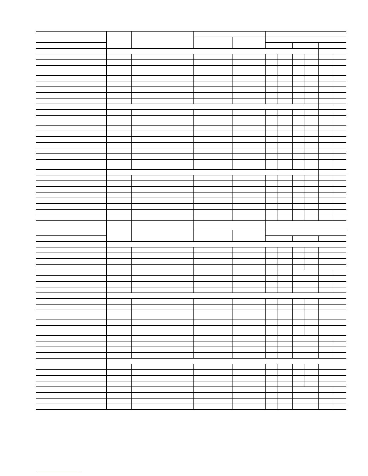
Table 1 — Control Inputs and Outputs
DESCRIPTION
Inputs SW2 SW3 SW1
Main Controller (PCB1) Addr = 1-16
Supply Air Temperature SAT Analog; 10K MCI 1 1 1 Up 1 Down 1 Up
VFD Duct Static Pressure DSP 4-20mA; Internally Powered 2 2 2 Up 2 Up 2 Down
COL/Safeties —
(Comprs.Status; Resister Bd.)
Fire Alarm/Shutdown FSD Switch closure 4 4 4 Up 4 Down 4 Down
Condenser Waterflow Switch CDWF Switch closure 5 5 5 Up 5 Down 5 Down
Remote Occupancy RMTOCC Switch closure 6 6 6 Up 6 Down 6 Down
Duct High Static Limit Switch DHS Switch closure 7 7 7 Up 7 Down 7 Up
Entering Water Temp. Sensor EWT Analog; 5K 8 8 8 Up 8 Down 8 Up
I/O Board (PCB2) Addr = 17-32
Mixed/Return Air Sensor MAT/RAT Analog; 10K MCI 1 1 1 Up 1 Down 1 Up
Filter Status Switch
(Dirty Filter Detect)
PhaseLossMonitor PHASE Switch closure 3 3 3 Up 3 Down 3 Down
External reset RESET 0-10VDC Externally Powered 4 4 4 Up 4 Down 4 Down
Water Econ. FreezeStat FREEZE Switch closure 5 — 5 Up 5 Down 5 Up
Differential Enthalpy ENTH Switch closure — 5 5 Up 5 Down 6 Down
Space Zone Sensor(s) SPT Analog; 10K MCI 6 6 6 Up 6 Down 7 Up
VFD Bypass Enable BYPASS Switch closure 7 7 7 Up 7 Down 8 Up
Refrigerant Pressure
(Compr.#1)
I/O Board (PCB3) Addr = 33-48
Tow e r S um p Te mp . TWRTEMP Analog; 10K MCI 1 1 1 Up 1 Up 1 Up
Building Pressure BSP 4-20mA; Internally Powered 2 2 2 Up 2 Down 2 Down
Leaving Water Temp. LWT Analog; 10K MCI 3 3 3 Up 3 Up 3 Down
Indoor Air Quality IAQ 4-20mA; Internally Powered — 4 4 Up 4 Down 4 Down
Indoor relative Humidity IRH 4-20mA; Internally Powered — 5 5 Up 5 Down 5 Down
Outside Air Temp. OAT Analog; 10K MCI — 6 6 Up 6 Up 6 Up
Unassigned —— ——————7Up
Unassigned —— ——————8Up
DESCRIPTION
Outputs SW4 SW5 SW6
Main Controller (PCB1)
Compressor #1 Relay CMP1 24VDC Discrete 1 1 1 Either 1 DO —
Compressor #2 Relay CMP2 24VDC Discrete 2 2 2 Either 2 DO —
Compressor #3 Relay CMP3 24VDC Discrete 3 3 3 Either 3 DO —
Compressor #4 Relay CMP4 24VDC Discrete 4 4 4 Either 4 DO —
VFD On/Off SF 24VDC Discrete 5 5 5 Either — 1 DO
VFD Speed Control SPEED 4-20mA modulating 6 6 6 Down — 2 AO
Alarm Pending ALARM1 24VDC Discrete 7 7 7 Either — 3 DO
Service Required ALARM2 24VDC Discrete 8 8 8 Either — 4 DO
I/O Board (PCB2)
Ventilation Output VENTOUT 24VDC Discrete 1 1 1 Either 1 DO —
Terminals Occupied OCCTRM 24VDC Discrete 2 2 2 Either 2 DO —
2-Position\
Reverse Operation Valve
Economizer Damper ECONO 4-20mA modulating — 3 3 Down 3 AO —
Modulating Valve Econ./
Head Pressure Control
Hot Water Coil Valve Control HWV 4-20mA modulating 5 5 5 Down — 1 AO
Heat Interlock Relay HIR 24VDC Discrete 6 6 6 Either — 2 DO
VFD Bypass Start BPSS 24VDC Discrete 7 7 7 Either — 3 DO
VAV Terminals Open DAMPERS 24VDC Discrete 8 8 8 Either — 4 DO
I/O Board (PCB3)
Electric Heat Control — Stage #1 HEAT1 24VDC Discrete 1 1 1 Either 1 DO —
Electric Heat Control — Stage #2 HEAT2 24VDC Discrete 2 2 2 Either 2 DO —
Electric Heat Control — Stage #3 HEAT3 24VDC Discrete 3 3 3 Either 3 DO —
Electric Heat Control — Stage #4 HEAT4 24VDC Discrete 4 4 4 Either 4 DO —
Water Pump Request PUMP 24VDC Discrete 5 5 5 Either — 1 DO
Tower Request TOWER 24VDC Discrete 6 6 6 Either — 2 DO
Modulating Exhaust Fan EXH 4-20mA modulating 7 7 7 Down — 3 AO
External Dehumidification DEHUM 24VDC Discrete 8 8 8 Either — 4 DO
LEGEND
AO — Analog Output
DO — Discreet Output
MCI — Precon Type II Thermistor
VAV — Variable Air Volume
VFD — Variable Frequency Drive
ABBREV. TYPE
CMP MUX Analog; 0-10VDC 3 3 3 Up 3 Down 3 Down
FLTS Switch closure 2 2 2 Up 2 Down 2 Down
PRES 4-20mA; Internally Powered 8 8 8 Up 8 Up — —
ABBREV. TYPE
ECONO 4-20mA modulating 3 3 Down 3 AO —
MODVLV 4-20mA modulating 4 4 4 Down 4 AO —
CONTROLLER I/O NO. DIP SWITCH SETTINGS
Water Econ. Units Air Econ.Units
CONTROLLER I/O NO. DIP SWITCH SETTINGS
Water Econ. Units Air Econ.Units
Switch No. and Position
Switch No. and Position
3
Page 4

STATUS
RED
(POWER)
GREEN
(IO BUS
COMMUNICATIONS)
YELLOW
(CNN BUS
COMMUNICATIONS)
Fig. 1 — CC6400 Control Module LEDs
Carrier Comfort Network Interface — The 50BV,XJ
units can be connected to the CCN (Carrier Comfort Network)
if desired. System elements are connected to the communication bus in a daisy chain arrangement. The negative pin of
each system element’s communication connector must be
wired to the respective negative pins, and positive pins on each
component must be connected to respective positive pins. The
controller signal pins must be wired to the signal ground pins.
Wiring connections for CCN must be made at the 3-pin plug.
At any baud rate (9600, 19200, 38400 baud), the number of
controllers is limited to 239 devices maximum. Bus length may
not exceed 4000 ft, with no more than 60 total devices on
any 1000-ft section. Optically isolated RS-485 repeaters are
required every 1000 ft.
NOTE: Carrier device default is 9600 baud.
The CCN Communication Bus wiring is field-supplied and
field-installed. It consists of shielded three-conductor cable
with drain (ground) wire. The cable selected must be identical
to the CCN Communication Bus wire used for the entire
network. See Table 2 for cable recommendations.
NOTE: Conductors and drain wire must be at least 20 AWG
(American Wire Gage), stranded, and tinned copper.
Individual conductors must be insulated with PVC, PVC/
nylon, vinyl, Teflon, or polyethylene. An aluminum/
polyester 100% foil shield and an outer jacket of PVC,
PVC/nylon, chrome vinyl, or Teflon with a minimum
operating temperature range of –20 C to 60 C is required.
The communication bus shields must be tied together at
each system element. If the communication bus is entirely
within one building, the resulting continuous shield must be
connected to ground at only one single point. If the communication bus cable exits from one building and enters another
building, the shields must be connected to the grounds at a
lightning suppressor in each building (one point only).
Optional and Field-Installed Accessory Sensors/
Devices —
accessories that add functionality and control. These options
and accessories are controlled by the CC6400 system as
described below.
NOTE: The CC6400 Control software includes all PCB1
functions, and most of the sensors/devices associated with
those functions are factory installed. However, some PCB1
sensors/devices must be field-connected to the proper terminal.
PCB2 devices are field-installed accessories. The CC6400
software includes these functions, but the actual sensor/device
must be installed and wired in the field. PCB3 is an accessory
control module. All PCB3 sensors/devices and software are
field-installed.
The 50XJ unit can be ordered with options and
Table 2 — Communication Cable Recommendations
MANUFACTURER PART NUMBER
Alpha 2413 or 5463
American A22503
Belden 8772
Columbia 02525
REMOTE OCCUPANCY CONTROL (PCB1) — This control is a field located switch, controller or timer input which,
when activated, tells system when to switch from Unoccupied
to Occupied mode.
When in Occupied mode, the unit turns on the supply fan
and controls supply fan speed to maintain a duct static set point
measured at the Duct Static Pressure Sensor (DSP). The unit
operates to provide conditioning to a set point. When in
Unoccupied mode, the unit provides no cooling/heating, or
controls to a ‘setback’ set point.
FIRE ALARM (PCB1) — The fire alarm is a control voltage
input to the 50XJ unit, which causes the controller to shut the
system down in the event of a fire.
CONDENSER WATER FLOW SWITCH (50XJ
PCB1) — This thermal dispersion type flow switch if factory
installed, is located in the unit waterline to ensure that there is
waterflow before allowing the unit to start the compressor(s). If
no flow is detected, then compressor operation and economizer
cooling is avoided until waterflow is again detected. An
warning light (yellow) is provided during this state.
HEAT INTERLOCK OUTPUT (50XJ PCB2) — This output
is activated whenever heating is activated, commanding the
VAV dampers to operate in heating control mode.
NOTE: In order to this output to function, the Terminal
Occupied output must also be on.
TERMINAL OCCUPIED (50XJ PCB2) — Terminal Occupied is activated to command VAV dampers to control to the
cooling set point. Terminal Occupied must be on along with
Heat Interlock for heating set point control to function.
EXTERNAL RESET INPUT (50XJ PCB2) — This modulating input (0 to 10 vdc) allows remote adjustment (upward) of
the Supply Air Temperature (SAT) sensor set point. The default
External Reset Input setting is 55 F. This variable input can
raise the set point by up to 20 F for a full-range input signal, or
to any point in between.
WATER ECONOMIZER COIL (50XJ PCB2) — This factoryinstalled option contains a water-to-air coil, two (2) electronic
motorized water valves, and related piping. Control of the water
economizer also requires a Mixed/Return Air Temperature
Sensor, a Condenser Water Inlet Temperature Sensor and an
Economizer Freezestat safety switch.
The electronic motorized water valves are each controlled
by the unit controller via separate 4 to 20 mA variable signals
to define variable valve position.
The Mixed/Return Air Sensor (MA_RA) is an air
temperature sensor located in the unit, between economizer
coil and evaporator.
The Condenser Water Inlet Temperature Sensor (CWT) is
located at the unit water inlet connection. This sensor receives
input power from the unit main controller and provides a linear
variable 1 to 5 vdc signal back to the controller. The full
temperature range is 32 to120 F.
The 50XJ units can be connected to two types of building
water systems: variable and fixed or constant flow control. In
either case, the economizer water valves are opened whenever
there is a call for Cooling and the Inlet Water Temperature is
colder than the Econ Start Set Point in the custom configuration.
4
Page 5

Dependencies
— Water Economizer option is enabled, and
Fan is On, and Inlet Water Temperature is below set point; or
from “Remote Scheduler,” or from “Remote Linkage.”
Economizer mode is switched to Off or no start if: there is
no condenser waterflow, Fire Input is On, Fan is not On, or Unoccupied mode is On.
Variable Waterflow Systems
— Whenever water economizer
is off, the economizer flow control valve is fully closed, and the
reverse flow valve directly to the condenser is fully open. Upon
engagement of the water economizer, the economizer flow control valve shall be controlled to maintain the MA_RA located
between the economizer coil and the DX cooling coil, at a temperature near the supply air set point. The the reverse flow valve
will be controlled in reverse of the economizer flow control
valve’s position. The following formula is an example: Reverse/
Head Press Ctrl output = 100 – two-position/Econo output.
When the unit is off, both valves are closed.
Constant Waterflow Systems
— Control of the economizer
flow control valve is same as for variable waterflow systems.
Control of the reverse flow control valve position will inversely
track the economizer flow control valve, such that the total sum
of the two valves open positions always equals 100%. The only
difference between the variable waterflow system and the
constant waterflow system is that for the constant flow system
when the unit is off, the economizer valve will be closed and
the reverse flow control valve will be open.
WATER ECONOMIZER COIL (50BV) — For the 50BV
unit, this factory-installed option contains a water-to-air coil, a
two-position diverting valve, and related piping. The water economizer is controlled by an Aquastat and a return-air thermostat.
HEATING COILS AND VALVE (50XJ PCB2) — Water or
steam heating options are factory installed. Each includes a
motorized, variable control water or steam flow control valve,
which can be factory supplied for field installation outside the
unit. Installed in the water or steam inlet pipe, this valve is
wiredtotheunitmaincontrollerandoperatesona4to20mA
signal. A Heating mode PID control is needed to control the
valve position (i.e., coil heating capacity) variably between 10
and 100%. The PID will control a set point to + 1° F; for VAV
Units this set point is at the Supply Air Temperature Sensor, or
as communicated from a remote thermostat.
HEAD PRESSURE CONTROL (50XJ PCB2) — Head Pressure Control is required for unit installations that will
experience entering condenser water temperatures of 55 F or
lower.
NOTE: Head Pressure Control is not needed or used in
conjunction with a Water Economizer. A refrigerant pressure transducer will monitor head pressure on compressor
circuit 1, allowing the unit main controller to regulate water
flow rate in the main water line entering the unit; i.e., flow
to all condensers. (Water header design to the condensers
will be optimized such as to provide relative flow rates to
each condenser based on its compressor capacity, enabling
successful waterflow control at the main entering pipe.)
There are two possible water valving configurations, as
outlined below.
Pressure transducer input is factory installed in the
discharge line of compressor circuit 1. It is provided 5 vdc by
the unit main controller and returns a signal 1 to 5 vdc linearly.
The sensor’s range is 0 to 550 psig.
Water Valve(s) Control
Variable Building Waterflow Systems — Variable waterflow
configurations use only one water valve in the main water
supply pipe. The factory installed valve is a normally open
motorized variable control type. The valve is controlled by a
4 to 20 mA signal from the main unit controller using the
Reverse/Head Press Ctrl output, which modulates to maintain
the head pressure set point (Setpoint 04).
Constant Building Waterflow Systems — Constant waterflow
configurations use two (2) water valves, only one of which is
in the main water supply pipe. The second valve is located in a
bypass pipe to the main outlet water pipe branched off of the
supply pipe immediately ahead of the first valve. This valve is
same type, but normally closed and is controlled in unison with
the first valve, but opposite position, such that the total opening
of the 2 valves always equals 100%.
VFD BYPASS (50XJ PCB2) — The VFD Bypass option
provides backup for the VFD Drive in VAV units. It uses a
manually operated rotary switch, which includes a series of
high voltage contacts. The bypass is a direct input to the unit
controller, and will be activated via a switch on the unit front
panel. When manually activated, the rotary switch takes the
VFD out of the fan power circuit and provides the 3-phase
power directly to the fan motor, running it at constant speed. A
low voltage control circuit ensures that the unit controller provides a signal to allow all VAV dampers to open fully before
the fan is turned on (at constant/full speed). A blue indicator
light located on the front of the unit indicates that the VFD Bypass is active. A High Duct Static Switch (HDS) shuts the fan
down if duct static exceeds a maximum setting.
VENTILATION OUTPUT (50XJ PCB2) — The ventilation
output is controller output signal (available for field connection)
to a field-supplied ventilation damper(s). This signal is activated
whenever the unit is in the occupied mode.
SPACE TEMPERATURE SENSOR (50XJ PCB2) — A fieldsupplied Carrier space temperature sensor is required to
maintain space temperature in sensor mode.
SUPPLY AIR RESET (50XJ PCB2) — Supply air temperature
set point may be reset using either the SPT or MA_RA.
SUPPLY AIR RESET (50BV) — Reset is provided by a
field-installed temperature sensor.
EXHAUST FAN CONTROL OUTPUT (50XJ PCB2) — This
output is activated whenever the unit is in the Occupied mode.
This is a modulating output that controls based on the Building
Pressure Input set point.
CONDENSER WATER PUMP/WATER TOWER (50XJ
PCB2) — This output (provided for field connection) is used
to control condenser water flow. Either an On/Off signal or a
variable output may be required for this feature.
PHASE LOSS/REVERSAL PROTECTION SWITCH
(50XJ PCB2) — This switch monitors VFD/Fan Motor supply leads to detect phase loss or reversal. If the switch detects
improper phasing, an input is sent to the unit controller, which
shuts the unit down. After a time delay, the controller attempts
to restart the unit.
A phase loss/reversal switch may be installed in the unit to
detect over/under voltage conditions and phase loss or reversal.
When the switch opens, the controller outputs are forced to off
with Safety forces, the alarm output will close and the red
alarm light will be lit. A system alarm will be generated and
displayed on the unit keypad. Unit reset is automatic when the
voltage and power phases have been restored.
FREEZE THERMOSTAT (FREEZSTAT) (50XJ PCB2) — The
Economizer Freezestat, used in conjunction with an optional
water economizer coil or heating coil, is a factory installed
averaging (capillary tube) air temperature sensor positioned in
the unit inlet airstream.
If the freeze protection switch contacts open the ventilation
request output will be closed for 15 minutes and the warning
light will light. If the freeze protection switch contacts are still
open after 15 minutes the supply fan will be stopped, all
compressor cooling will stop, the economizer valve will open
to 100%, the pump request output will remain on, and the
alarm light will light. This will maintain condenser water flow
through the coil to prevent freezing the coil while stopping all
other operations that could have contributed or will be affected
5
Page 6
by the freeze condition. Unit reset is automatic when the
contacts on the freeze protection switch close again. The
contacts on the freeze protection switch open below 37 F.
TOWER SUMP TEMPERATURE SENSOR (50XJ
PCB3) — This sensor is used for monitoring (only) the tower
sump temperature.
LEAVING WATER TEMPERATURE SENSOR (50XJ
PCB3) — This sensor is used for monitoring (only) the leaving water temperature.
BUILDING STATIC PRESSURE SENSOR (50XJ
PCB3) — This sensor is used to control both the speed of the
building exhaust fan and the building static pressure.
INDOOR AIR QUALITY (CO
PCB3) — This sensor monitors CO
)SENSOR(50XJ
2
levels.
2
INDOOR RELATIVE HUMIDITY SENSOR (50XJ
PCB3) — This sensor monitors and controls the humidity
control relay.
OUTDOOR AIR TEMPERATURE SENSOR (50XJ
PCB3) — This sensor is used to monitor outdoor air and
broadcast the value over the Carrier Comfort Network (CCN).
STAGE HEAT RELAYS (50XJ PCB3) — These relays control up to four stages of electric heat, or other heating methods.
PUMP REQUEST RELAY (50XJ PCB3) — This relay turns
on a tower pump when requested.
TOWER REQUEST/CONTROL RELAY (50XJ PCB3) —
This relay is used to activate a tower fan.
BUILDING EXHAUST FAN SPEED CONTROL (50XJ
PCB3) — This output controls building exhaust fan speed.
HUMIDITY CONTROL RELAY (50XJ PCB3) — This relay
controls a humidifier or dehumidification device.
Wiring Control Devices — Standard controls for the
50XJ require no field-wiring. Standard 50XJ controls include:
Supply Air Temperature (SAT), Duct Static Pressure (DSP),
Duct High Static Limit Switch (DHS), Filter Status Switch
(FLTS), Entering Water Temperature (EWT), Compressor Status (CSMUX), Supply Fan Start/Stop (SF), Supply Fan Speed
(SPEED), and Mixed/Air Return/Air sensor (MA_RA).
NOTE: The MA_RA sensor will be located in the return air
steam if the unit does not have a water economizer, and in
the mixed airstream if the unit is equipped with a water
economizer.
For the 50BV unit, standard controls include: Duct Static
Pressure (DSP), Duct High Static Limit Switch (DHS), Compressor Status (CSMUX), Supply Fan Start/Stop (SF), and
Supply Fan Speed (SPEED).
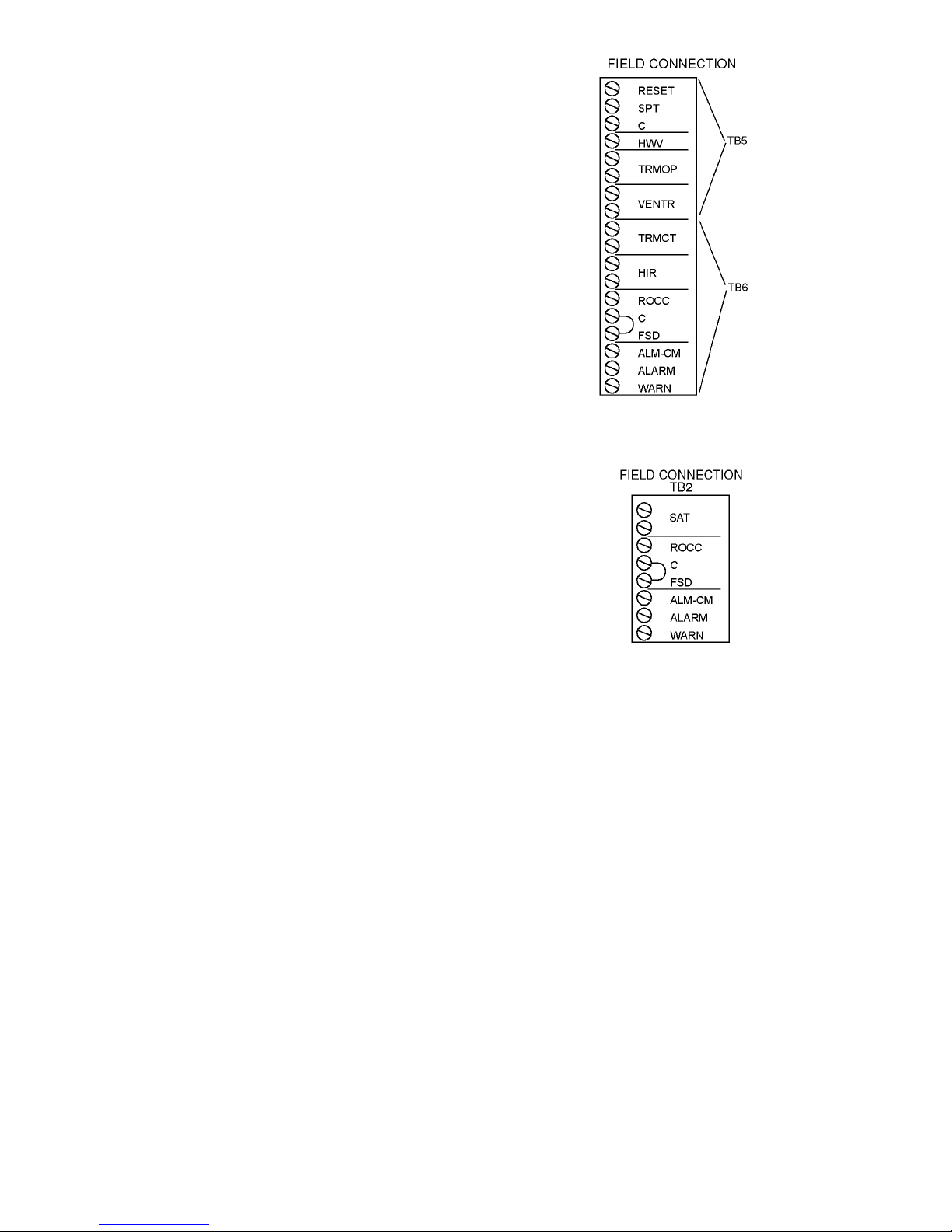
For the 50XJ unit, optional controls will be wired to the
field terminal blocks (TB5 and TB6) provided. Refer to
Fig. 2A and the descriptions below.
For the 50BV unit, optional controls are wired to field
terminal block TB2 as shown in Fig. 2B.
EXTERNAL 0 TO 10 VOLT DC RESET SIGNAL (RESET)
(50XJ PCB2) — This field-supplied 0 to 10 vdc signal is used
to reset the 50XJ supply-air temperature. The controller will
scale the signal to provide 0 reset at 0 volts and 20 degrees of
reset at 10 volts. Wire the positive of the signal to the RESET
terminal and the negative to the C or common terminal.
SUPPLY AIR RESET (50BV) — Use a 5k ohm sensor
installed at the Entering Water Temperature sensor (EWT)
location on PCB1. For space temperature averaging, two 10k
ohm Space Temperature Sensors (SPT) can be wired in parallel.
SPACE TEMPERATURE SENSOR (50XJ PCB2) — The
space temperature sensor (33ZCT55SPT) is used in the following cases:
• When using the optional water economizer and not using
Carrier’s ComfortID™ System.
Fig. 2A — Field Terminal Blocks for 50XJ Unit
Fig. 2B — Field Terminal Block for 50BV Unit
• To determine the average temperature of the space being
served.
• To determine supply-air temperature reset, occupied
heating, unoccupied heating and cooling (refer to
Sequence of Operation in the Start-Up section.).
To wire the sensor, perform the following (see Fig. 3).
Identify which cable is for the sensor wiring.
1. Strip back the jacket from the cable for at least
3 inches. Strip
1
/4-in. of insulation from each conductor. Cut the shield and drain wire from the sensor end
of the cable.
2. Wire the sensor to the SPT and C terminals on the field
terminal block (TB5). A typical 10K thermistor such
as the 33ZCT55SPT sensor may be used. If the SPT
sensor is not installed and the MA_RA (mixed air/
return air) sensor is configured for return air, the 50XJ
unit will use this sensor to control supply air reset,
occupied heat, and unoccupied heating and cooling
See Fig. 4 for space temperature sensor averaging.
HOT WATER OR STEAM VALVE (HWV) (50XJ
PCB2) — The HWV terminal supplies the positive signal to
control a 4 to 20 mA hot water or steam valve for occupied and
unoccupied heat. Connect the common side of the valve to the
C terminal or an equipment ground.
6
Page 7

AIR TERMINALS AND FRESH AIR DAMPER (50XJ
PCB2) — The VAV Terminal Open (TRMOP), Ventilation
Output (VENTR), VAV Terminals Control (TRMCT), and
Heat Interlock Relay (HIR) terminals provide dry contacts to
command the VAV terminals open; a ventilation damper open;
VAV terminals to control to their cooling set points; and VAV
terminals to control to their heat set points, respectively.
REMOTE OCCUPANCY (ROCC) (TB2 50BV, TB6
50XJ) — The 50XJ,BV unit may be commanded by a remote
control system or a twist timer to become occupied and run
when a set of dry contacts close. In order for this to occur, wire
the contacts to ROCC and C.
SMOKE DETECTOR/FIRE ALARM SHUTDOWN (FSD)
(TB2 50BV, TB6 50XJ) — To allow a smoke detector to shut
the 50XJ,BV unit down, remove the jumper from FSD to C
and wire these terminals to a set of normally closed contacts on
the smoke detector.
ALARM (ALARM) AND WARNING (WARN) OUTPUTS
(TB2 50BV, TB6 50XJ) — Two dry contacts output a discrete signal when the alarm and warning lights on the display
are lit. To pick up the alarm output signal, wire between the
ALARM and ALM-CM terminals. To pick up the warning
output signal, wire between the WARN and ALM-CM
terminals.
45
61
RED(+)
WHT(GND)
BLK(-)
BRN (GND)
BLU (SPT)
CCN COM
SENSOR WIRING
SW1
2
3
SEN
Fig. 3 — Space Temperature Sensor
Typical Wiring (33ZCT55SPT)
RED
BLK
J6
6
7
RED
BLK
RED
BLK
SENSOR 1 SENSOR 2 SENSOR 3 SENSOR 4
RED
BLK
RED
BLK
SPACE TEMPERATURE AVERAGING — 4 SENSOR APPLICATION
J6
6
7
RED
BLK
BLK
SENSOR 1
RED
RED
BLK
RED
BLK
SENSOR 2
RED
BLK
SENSOR 3
RED
BLK
LEGEND
Field Wiring
SPACE TEMPERATURE AVERAGING — 9 SENSOR APPLICATION
BLK
SENSOR 4
RED
RED
BLK
SENSOR 7
SENSOR 5
SENSOR 8
Fig. 4 — Space Temperature Averaging
7
SENSOR 6
RED
BLK
SENSOR 9
Page 8

CONTROLS AND FUNCTIONS
Table 4 — Operative Keys
Using the Local Interface Display —
The Local
Interface Device (LID) is a CCN operator interface that gives
the user the capability to view and modify all configuration and
service data for the CC6400 control system. The LID also
allows the user to override all point display and maintenance
data.
MENU STRUCTURE — The LID operates on a hierarchy of
four levels (menus).
The top level contains the LID’s major functions. Each
function has a corresponding key on the LID. For an explanation of each function key, refer to Table 3.
The second level separates the major functions (items) into
types with corresponding type numbers that can be used for
quick access.
The third level gives the user the capability to access each
occurrence of an item. For example, the application may
require two DO (Discreet Output) — Analog Comparison
algorithms. Thus, the CC6400 Controller would have two
occurrences of the DO — Analog Comparison algorithm.
The fourth level gives the user the capability to access maintenance and configuration data associated with the selected
occurrence of the item.
DEFAULT SCREEN — Figure 5 shows the LID. The LID’s
screen provides the user with the 24-character controller name
and the controller’s current time, date, and alarm status. This
screen appears when the LID is powered up and communicating with the controller or there is no keyboard activity for
10 minutes.
KEYPAD AND DISPLAY — The LID consists of a keypad
with 8 function keys, 4 operative keys, 12 numeric keys (0 to
9,., and -) and a two-line, alphanumeric liquid crystal display
(LCD). Each line on the LCD can display up to 24 characters.
See Fig. 5. Table 4 defines the purpose of the LID’s operative
keys. Table 5 defines the purpose of the LID’s numeric keys.
Table 3 — LID Function Keys
OPERATIVE
KEYS
Status — gives access to maintenance
values and configuration data for points.
Alarm — gives access to maintenance
and configuration data for alarms.
History — gives access to maintenance
and configuration data for history system
functions.
Service — gives access to maintenance
and configuration data for service system
functions.
Setup — gives access to configuration
data for setup system functions.
Schedule — gives access to maintenance
and configuration data for schedules.
Algorithm — gives access to maintenance
and configuration data for AO, DO, and global
algorithms. It also gives access to BEST
custom programs.
Edit — gives the capability to switch from
Status mode to Edit (configuration) mode for
the selected item.
LEGEND
AO — Analog Output
DO — Digital/Discreet Output
USE
++™
OPERATIVE
KEYS
CLEAR
ENTER
Clear — performs three operations:
• Cancels a data entry before the user
presses Enter, thus leaving the current
value unchanged.
• Returns a forced point to automatic
control.
• Redisplays the previous menu level.
Enter — performs two operations:
• Selects the displayed item, thus displaying
either its maintenance or configuration
data, depending on whether the user is in
the Status mode or the Edit mode.
• Accepts the value entered in a configuration
decision as new configuration data or as a
force.
Down arrow — displays the next configured
item or decision. When the last configured
item or decision is displayed, the LID
re-displays the first configured item or
decision. For example, when the user presses
the down arrow key while viewing the last
configuration decision of an algorithm, the LID
re-displays the first configuration decision.
Up arrow — Displays the previous configured
item or decision.
USE
Table 5 — Numeric Keys
OPERATIVE
KEYS
-
Numeric keys
Performs two operations:
• Separates items, such as an algorithm from
its occurrence or hours from minutes.
• Serves as a decimal point in numeric values.
Performs two operations:
• Negates the value of numeric keys.
• Clears current data entry value any time it is
not the first key pressed during the data
entry sequence.
USE
VIEWING MODES — The user can view items in either the
Status (maintenance) mode or the Edit (configuration) mode.
Status Mode
— When the user first powers up the LID, it
displays the CC6400 controller items in Status (maintenance)
mode. The user may view the current value or status of an item
in Status mode without actually logging on to the Controller.
Knowing the current values or status of items can be useful
when troubleshooting. For example, the user could determine
if a point was forced.
NOTE: Not all items have maintenance data. If the item you
select does not have maintenance data, the LID will display
“No maintenance.”
Accessing Items in Status Mode
— The user can access
maintenance data in Status mode in two ways:
• Pressing the appropriate function key (i.e., )
ALRM
once to access a category (i.e., alarms) and then continuing to press that key ( ) to scroll through all the
ALRM
items in that category (i.e., Limit Alarm, Set point
Alarm, Discrete Alarm, First Out Alarm, Runtime
Alarm, and Number of Starts Alarm). Press to
ENTER
display the first maintenance decision.
NOTE: Scrolling by repeatedly pressing the function key
displays the name of all the items in that category, whether
or not they are actually configured. Scrolling by pressing
the up or down arrow displays only the configured items
within that category.
8
Page 9

• Pressing the appropriate LID numeric key (i.e., 2) and
the appropriate function key (i.e., ) to directly
ALRM
access an item without having to scroll through all the
items in that category. Press to display the first
ENTER
maintenance decision.
Edit Mode
— Because the LID first displays items in Status
mode when it is powered up, the user must log on to the connected CC6400 Controller and press the key to
EXPN/EDIT
switch to Edit mode.
While in Edit mode, the user can change the configuration
of items. For example, the user could change the value of an algorithm’s configuration decision.
NOTE: Not all items have configuration data. If the item
selected does not have configuration data, pressing the
EXPN/EDIT
key will have no effect. The LID will display
“No configuration.”
Accessing Items in Edit Mode
— The two ways to access
items in Edit mode are the same as in Status mode, except for
an additional step — pressing the key.
EXPN/EDIT
The user can access configuration data in Edit mode in two
ways:
• Pressing the appropriate function key (i.e., ) once
to access a category (i.e., alarms), pressing
and then continuing to press that key ( ) to scroll
ALRM
EXPN/EDIT
ALRM
through all the items in that category (i.e., Limit Alarm,
Set point Alarm, Discrete Alarm, First Out Alarm,
Runtime Alarm, and Number of Starts Alarm).
NOTE: Scrolling by repeatedly pressing the function key
displays the name of all the items in that category, whether
or not they are actually configured. Scrolling by pressing
the up or down arrow displays only the configured items
within that category.
• Pressing the appropriate LID numeric key (i.e., 2),
the appropriate function key (i.e., ), and
EXPN/EDIT
to directly access an item without having
ALRM
to scroll through all the items in that category.
QUICK ACCESS IN EITHER STATUS OR EDIT
MODE — Use Table 6 as a reference to directly access
CC6400 Controller items using a LID in either Status or Edit
mods. For example, to access maintenance data for the AO —
Heating VAV algorithm, press , , and . To
6 ALGO ENTER
access configuration data for the AO (Analog Output) —
Heating VAV algorithm, press , , ,
and . If the database consisted of two AO — Heating
ENTER
VAV algorithms, to access the second one, press , (decimal), ,, ,and .
2 ALGO EXPN/EDIT ENTER
6 ALGO EXPN/EDIT
6 .
FUNCTION
KEYS
OPERATIVE
KEYS
OMNIZONE VPAC
12:00 02-06-04
EXPN
STAT
SET
EDIT
SCHD
1
4
7
–
NUMERIC KEYS
Fig. 5 — Local Interface Display (LID)
3
2
5
6
8
9
.
0
TEST
SRVC
ALRM
HIST ALGO
CLEAR
ENTER
FUNCTION
KEYS
OPERATIVE
KEYS
9
Page 10

Table 6 — Quick Access Chart
LID
NUM.
KEY
1 AO—Adaptive Control Hardware Points Alarm History Function Definition Limit Set Clock Occupancy
2 AO—Cooling CV Software Points Analog Point Trace Channel Definition Setpoint Real Time Clock Setpoint
3 AO—Cooling VAV Temperature Input Discrete Point Trace System Definition Discrete Controller Password Holiday
4 AO—Fan Tracking Milliamp Input Consumable Channel Setpoint Definition First out N/A S/W Setpoint
5 AO—Heating CV Custom Milliamp Input Internal Consumable Database Control Runtime N/A Network Time
6 AO—Heating VAV Voltage Input Runtime Channel Comfort Controller # of starts N/A N/A
7 AO—Humidity Control Custom Voltage Input N/A CCN Control N/A N/A N/A
8 AO—Mixed Air CV w/IAQ Sensed Discrete Input N/A LID Preferences N/A N/A N/A
9 AO—Mixed Air VAV w/IAQ Latched Discrete Input N/A N/A N/A N/A N/A
10 AO—Permissive Interlock Pulsed Discrete Input N/A N/A N/A N/A N/A
11 AO—Reset Milliamp Output N/A N/A N/A N/A N/A
12 AO—Shared Transducer Custom Milliamp Output N/A N/A N/A N/A N/A
13 AO—Static Pressure Voltage Output N/A N/A N/A N/A N/A
14 DO—Analog Custom Voltage Output N/A N/A N/A N/A N/A
15 DO—DX-Staging VAV Discrete Output N/A N/A N/A N/A N/A
16 DO—Electric Heat CV Stepper Motor Output N/A N/A N/A N/A N/A
17 DO—Electric Heat VAV Discrete Software Point N/A N/A N/A N/A N/A
18 DO—Enthalpy Comparison Analog Software Point N/A N/A N/A N/A N/A
19 DO—Interlock Network Data Out N/A N/A N/A N/A N/A
20 DO—Lighting Control Network Data In N/A N/A N/A N/A N/A
21 DO—Permissive Interlock N/A N/A N/A N/A N/A N/A
22 DO—Pump Control N/A N/A N/A N/A N/A N/A
23 DO—Prop Ther mo N/A N/A N/A N/A N/A N/A
24 DO—Prop Thermo 2 Pipe N/A N/A N/A N/A N/A N/A
25 DO—Prop Thermo 4 Pipe N/A N/A N/A N/A N/A N/A
26 DO—Staged Thermostat N/A N/A N/A N/A N/A N/A
27 DO—Staging Control N/A N/A N/A N/A N/A N/A
28 DO—Time Clock N/A N/A N/A N/A N/A N/A
29 DO—Time Clock w/Check N/A N/A N/A N/A N/A N/A
30 AOSS Schedule N/A N/A N/A N/A N/A N/A
31 Network Broadcast N/A N/A N/A N/A N/A N/A
32 Linkage/AOSS Schedule N/A N/A N/A N/A N/A N/A
33 NTFC w/Enthalpy Check N/A N/A N/A N/A N/A N/A
34 Sensor Group N/A N/A N/A N/A N/A N/A
35 WSM Air Source N/A N/A N/A N/A N/A N/A
36 WSM Cool Source N/A N/A N/A N/A N/A N/A
37 Custom Program N/A N/A N/A N/A N/A N/A
AO — Analog Output
AOS S — Adaptive Optimal Star t/Stop
CV — Constant Volume
DO — Digital Output
IAQ — Indoor Air Quality
N/A — Not Available
NTFC — Nighttime Free Cooling
VAV — Variable Air Volume
WSM — Water System Manager
Algorithms
(ALGO)
LEGEND NOTES:
Status
(STAT)
LID FUNCTION KEYS
History
(HIST)
1. To change from Edit mode to Status mode, press or press
EXPN/EDIT
2. Not all available selections will have items to select in sublevels.
Service
(SRVC)
again.
Alarm
(ALRM)
Setup
(SET)
Schedules
CLEAR
(SCHD)
Automatic Run Test — The 50BV,XJ unit controls are
programmed with an automatic run test that checks connection
and operation of major components. To perform the run test:
Verify that the control display (LID device/System Monitor)
interface cable is connected to internal jack on main controller;
that the fire alarm/shutdown switch input (FSD) has a factory
jumper or field input; that Bypass (if installed) is set in the
DRIVE position; and that the Local/Off/Remote switch is set to
the REMOTE position.
NOTE: When the Local/Off/Remote switch is in the
REMOTE position, the controller time schedule is pre-set
(from the factory) as unoccupied. This means that the unit
will not turn on until the run test is enabled. However, if the
controller schedule has already been modified in the field,
and the current time of day is occupied, then the supply fan
will start. The run test will shut the fan down when it
begins. The run test will complete and then the supply will
automatically restart.
NOTE: If the Local/Off/Remote switch is in the OFF position, it is normal for the red alarm light on the display panel
to be lit, indicating that the unit is disabled.
NOTE: If the red light stays on when the switch is moved to
REMOTE, or if any other problems occur during the run
test, refer to the Troubleshooting section of this manual.
To perform the Run Test:
1. Turn unit power on.
The LID display will show the controller identification, time and date (Fig. 5):
OMNIZONE VPAC
hh:mm mm-dd-yy
10
Page 11

2. Press 3 and then . The LID display will show:
SET
Controller Password
3. Press . The LID display will show:
ENTER
LogintoController
Enter Password
NOTE: The LID display has two modes: Edit mode and
Status/Maintenance mode. If the LID display is in Edit
mode, then the display will only show the word “password.” Press the key to toggle to the Status
EXPN/EDIT
mode.
Press the to display:
EXPN/EDIT
LogintoController
Enter Password
4. Key in the password and press .
ENTER
NOTE: The default password is 1111.
5. The LID display will show:
LogintoController
Logged In
NOTE: At this point, for the 50BV unit only, the run
test will follow these steps:
a. Press 37 . The display will show:
ALGO
Custom Program
b. Press . The display will show:
ENTER
2.0 Global Dictionary
OMNIZONE
c. Press (NOTE: Display will flash,
EXPN/EDIT
indicating that the device is now in edit mode.)
The display will show:
2.0 Global Dictionary
OMNIZONE
d. Press . The display will show:
ENTER
Compressor Stages
4.00
NOTE: A 50BV unit with only 2 compressors will
display 2.00. Skip to Step 6.
e. Input 2.00 and Press . The display will show:
ENTER
Compressor Stages
2.00
6. Press . The LID display will show:
STAT
Hardware Points
7. Press again. The LID display will show:
STAT
Software Points
8. Press . The LID display will show:
ENTER
Compressor 1 Status
9. Press 6 times. The LID display will show:
Factory/Field Test
Stop
10. Press 1 then , The LID display will show:
ENTER
Factory/Field Test
Start
NOTE: At this point, the yellow warning light on the
display panel will be lit and will stay on throughout the
run test. After each successful step, the red alarm light
will blink once.
11. The control module will now check if there is input from
BYPAS(50XJ),DHS,FSD,SAT,DSP,andCSMUX.
If the control does not receive open/open/closed/
in range/in range/in range, the red alarm LED will go
on and the test will stop.
If the inputs are OK, the red alarm LED blinks once
and the test continues.
12. Next, the control forces the Supply Fan (SF) and all of the
Compressors (COMP) off, and waits 15 seconds.
For the 50XJ unit, if the REMOTE LED and AUTO
LED on the VFD display are on, the red LED blinks
once and the test continues.
NOTE: For the 50XJ unit, if the controller is configured with a water Economizer, the delay is 2 min. and
both valves are commanded to 0%. Both water valves
will close.
13. The control forces SF on and SPEED to 20 percent and
then waits 30 seconds.
If the VFD display shows “10.6 Hz,” the Remote and
Auto LEDs blink, and the fan goes on, then the red LED
on the control module blinks once and the test continues.
NOTE: For the 50XJ unit, if the controller is configured with a water Economizer the delay is 2 min. and
Econo valve is commanded to 100%. The economizer
valve will open and the RVS/HD (reverse/head
pressure) valve will remain closed.
14. The control forces SF on and SPEED to 35 percent and
then waits 30 seconds.
If the VFD display shows “20.0 Hz,” the Remote and
Auto LEDs blink, and the fan goes on, then the red LED
on the control module blinks once and the test continues.
NOTE: For the 50XJ unit, if the controller is configured
with a water Economizer the delay is 2 min. and RVS/
HD valve is commanded to 100%. The economizer valve
is commanded to 0% and the RVS/HD valve will open.
15. The control forces SF off then waits 15 seconds.
If the VFD display shows “Off,” the Remote and Auto
LEDs are off, and the fan goes off, then the red LED on
the control module blinks once and the test continues.
NOTE: For the 50XJ unit, if the controller is configured
with a water Economizer both valves are commanded
to 0%. The economizer valve and RVS/HD will close.
NOTE: For the 50BV unit, the steps below (16-24)
will be completed for the number of compressors
configured.
16. The control forces CMP1 (compressor 1) on then waits
5 seconds.
If CSMUX is not in range the red LED will go on and
the test will stop.
If CSMUX is in range, the red LED blinks once and
the test continues.
17. The control forces CMP1 off.
18. The control forces CMP2 (compressor 2) on then waits
5 seconds.
If CSMUX is not in range the red LED will go on and
the test will stop.
If CSMUX is in range, the red LED blinks once and
the test continues.
19. The control forces CMP2 off.
20. The control forces CMP3 (compressor 3) on, if configured, then waits 5 seconds.
If CSMUX is not in range the red LED will go on and
the test will stop.
If CSMUX is in range, the red LED blinks once and
the test continues.
21. The control forces CMP3 off.
11
Page 12

22. The control forces CMP4 (compressor 4) on, if configured, then waits 5 seconds.
The LID display shows:
Factory/Field Test
Stop
The yellow LED will go off, and the red LED will go
off.
23. The control forces CMP4 off.
24. The run test is complete.
Power Up the LID Display — After completing the
automatic run test, perform the following procedures to change
the controller password, set the controller clock, configure
schedules, set parameters, view settings, and view alarm
history.
1. Set the Remote/Local/Off switch on the front of the unit to
the OFF position. This prevents operation of the fan and
compressors while still providing power to the unit controls.
NOTE: When the switch is in the OFF position, the red
alarm LED will be lit; this is normal. The bypass point
will also indicate OK.
2. If the unit access panel (for power and controls) is still on
the unit, remove it in order to view the control modules
during start-up.
3. Switch the main unit power disconnect to ON.
When power is applied to the OMNIZONE™ System
Control panel, the red LED on the top front of the processor
module will flash at a rapid pace (about twice a second) for the
first 30 to 60 seconds. This rapid flash will then be replaced by
a slower paced flash (about once per second).
The green LED below the red LED will start flashing. This
LED indicates input/output communications for accessory
input output modules and the LID display.
The yellow LED will flash when the controller is broadcasting CCN messages to a laptop or other computer.
The third LED from the bottom of the controller (PCB1)
will light.
The LID display will show the controller identification,
time and date as shown below.
OMNIZONE VPAC
hh:mm mm-dd-yy
Log On to the LID Display — ToLogOntotheLID
display, perform the following procedure:
1. Press 3 and then . The LID display will show:
Controller Password
2. Press . The LID display will show:
3. Key in the password and press .
ENTER
LogintoController
Enter Password
NOTE: The LID display has two modes: Edit mode and
Status/Maintenance mode. Edit mode allows the user to
change settings on the configurations screens. Status/
Maintenance mode only allows the user to look at the
settings.
If the LID display is in Edit mode, then the display will
only show the word “password.” Press the
EXPN/EDIT
sure the LID display shows:
LogintoController
Enter Password
NOTE: The default password is 1111.
SET
key to toggle to the Status mode. Make
ENTER
4. The LID display will show:
LogintoController
Logged In
NOTE: The user will be automatically logged off after
15 min. of non-use.
Change the Default Password — To change the
default password, perform the following procedure:
NOTE: The password must have already been entered to
perform this procedure.
1. Press 3 and then . The LID display will show:
Controller Password
2. Press . The LID display will show:
3. Press . The LID display will show:
4. Enter the new password (up to 6 digits) and press
5. Press twice to leave the password screen and re-
ENTER
LogintoController
Logged in
EXPN/EDIT
Password
1111 (default password, or previous password entered)
ENTER
Password
(password just entered)
NOTE: Remember this password; write it down.
CLEAR
turn to the default display screen.
SET
. The LID display will show:
Set the Clock — The user must be logged in to set the
clock. To set the clock, perform the following procedure:
1. Press 1 and then . The LID display will show:
Set Clock
2. Press . The LID display will show:
3. Press . The LID display will show:
4. Enter the time. The time is entered in military time (for
5. Enter the day of week. The numbers 1 through 7 corre-
6. Enter the number of the corresponding month (1 through
7. Enter the day of the month. Press then press
ENTER
No Maintenance
NOTE: There is no maintenance information regarding
setting the clock.
EXPN/EDIT
Time
00:00
example 14.59 for 2.59 pm). Press then press
the button. The LID display will show:
Day of Week
1
spond to the days of the week (1 = MON, 2 = TUE,
3 = WED, 4 = THUR, 5 = FRI, 6 = SAT, 7 = SUN). Press
ENTER
Month
1
12). Press then press . The LID display
will show:
Day
1
. The LID display will show:
Ye a r
95
SET
ENTER
then press . The LID display will show:
ENTER
ENTER
12
Page 13

8. Enter the last two digits of the current year. Press
ENTER
then press . The LID display will show:
Update Clock
No
9. Press 1 and then to cause the controller to
ENTER
update the clock. The LID display will flash. Press
CLEAR
twice to view the default display and the clock
should update to the input time and date.
Configure Schedules — Schedules are one method of
starting and stopping the unit at specified intervals. To configure the schedules, perform the following procedure:
1. Press 1 and then . The LID display will show:
SCHD
Occupancy Algorithm
2. Press . The LID display will show:
ENTER
Time Schedule
Enter to select
3. Press . If the LID display shows “MODE 0” then
ENTER
the user is in Maintenance mode and the LID display is
showing the maintenance information for the occupancy
schedule. Press to enter the configuration
EXPN/EDIT
mode. The LID display will show:
Manual Override Hours
0 hours
This is the first configuration for each occupancy
algorithm and is used to put the schedule in or out of
occupancy override for the number of hours entered.
4. Press . The LID display will show:
Period 1: Day of week
00000000
The eight digits represent if this period should apply to
certain days of the week or holidays. The digits representM,Tu,W,Th,F,Sa,Su,andHol,respectively.
Enter a series of 0s or 1s with a 1 corresponding to the
days that this period should apply to and a 0 for the
days that this schedule should not apply to. As an
example, entering 11111000 would make the schedule
apply to days Monday through Friday and not apply to
Saturday, Sunday, or Holidays.
5. Press the button. The LID display will show:
Period 1 occupied from
00:00
6. Input the Occupancy Start time for this period.
NOTE: 12.00 represents 12:00 pm.
7. Press the to input the Occupied To time for period 1.
8. Input the days and times for periods 2 through 8 as
required.
9. Press clear to leave the occupancy programming.
Program Set Points — To program the set points,
perform the following procedure:
1. Press 2 and then . The LID display will show:
Set point Schedule
2. Press . The LID display will show:
ENTER
Supply Fan Status
SETPT01
3. Press .
ENTER
SCHD
4. If “No maintenance” is displayed, press to
EXPN/EDIT
view the set point information. The LID display will
show:
Occupied Lo Set point
0.30 ″ H2O
This is the pressure set point below which the fan is
considered to be off.
5. Press . The LID display will show:
Occupied Hi Set point
0.40 ″ H2O
This is the pressure set point above which the fan is
considered to be on.
The down or up arrow will also display the Unoccu-
pied Low and High Temperature set points. These
values should be kept the same as the occupied values.
6. Setpoint 02 internally coordinates the supply air set point
reset in several of the algorithms and can not be modified.
Setpoint 03 is used for comparison by the unit to return
air, Space temperature or Average space temperature
through linkage to determine when to start reset of the
supply air when occupied, when to turn on heat and
disable cooling when occupied and when to bring the unit
on for unoccupied heating or cooling.
Setpoint 04 is used to set the head pressure set point if
the unit is ordered with the head pressure control
option. Only the Occupied Low set point may be
modified the other values will change to the Occupied
low valued shortly after it is modified so that all the
values remain the same.
Setpoint 05 is used to set the supply air static pressure the
unit should maintain. Only the Occupied Low set point
may be modified the other values will change to the
Occupied low value shortly after it is modified so that all
the values remain the same. The set point in the static
pressure control algorithm will also follow and cannot be
modified in the algorithm configuration screens.
Setpoint 06 is the Supply air temperature set point.
Only the Occupied Low set point may be modified the
other values will change to the Occupied low value
shortly after it is modified so that all the values remain
the same. The set point in DX VAV staging and some
of the other algorithms will also follow and cannot be
modified in the algorithm configuration screens.
Setpoint 07 is the building pressure set point for the
building pressure control of a variable speed exhaust
fan from a field-supplied module. Only the Occupied
Low set point may be modified the other values will
change to the Occupied low value shortly after it is
modified so that all the values remain the same.
Setpoint 08 is the raw milliamp set point for the building pressure control and is tied to Setpoint 07 for the
sensor range selected in the custom programming
configuration. Several choices of building static
pressure sensors may be purchased and supplied for
building pressure control.
Setpoint 09 is used for the humidification/dehumidification
output from a field-supplied module. This set point may be
modified to enable the Humidity output to either humidify
or dehumidify when the indoor relative humidity (IRH)
exceeds the set point.
Table 7 lists the available controller set points and their
default values.
7. Pressing the button will take the user out of the
CLEAR
set point configuration mode.
13
Page 14

Table 7 — Controller Set Points
DESCRIPTION
DISPLAY
SCREENS
OMNIZONE::SETPT01:
Supply fan Status
Occupied Lo Setpoint 0.3 in H2O OccLow
Occupied Hi Setpoint 0.4 in H2O OccHgh
Unoccupied Lo Setpoint 0.3 in H2O UnOccLow
Unoccupied Hi Setpoint 0.4 in H2O UnOccHgh
OMNIZONE::SETPT02:
VAVRESETbaseline
Occupied Lo Setpoint 0 dF OccLow
Occupied Hi Setpoint 0 dF OccHgh
Unoccupied Lo Setpoint 0 dF UnOccLow
Unoccupied Hi Setpoint 0 dF UnOccHgh
OMNIZONE::SETPT03:
Heat\Cool Mode & Reset
Occupied Lo Setpoint 70 dF OccLow
Occupied Hi Setpoint 74 dF OccHgh
Unoccupied Lo Setpoint 55 dF UnOccLow
Unoccupied Hi Setpoint 85 dF UnOccHgh
OMNIZONE::SETPT04:
Head Pressure Control
Occupied Lo Setpoint 225 PSIG OccLow
Occupied Hi Setpoint 225 PSIG OccHgh
Unoccupied Lo Setpoint 225 PSIG UnOccLow
Unoccupied Hi Setpoint 225 PSIG UnOccHgh
OMNIZONE::SETPT05:
Supply Static Pressure
Occupied Lo Setpoint 1.5 in H2O OccLow
Occupied Hi Setpoint 1.5 in H2O OccHgh
Unoccupied Lo Setpoint 1.5 in H2O UnOccLow
Unoccupied Hi Setpoint 1.5 in H2O UnOccHgh
OMNIZONE::SETPT06:
Supply Air Temperature
Occupied Lo Setpoint 55 dF OccLow
Occupied Hi Setpoint 55 dF OccHgh
Unoccupied Lo Setpoint 55 dF UnOccLow
Unoccupied Hi Setpoint 55 dF UnOccHgh
OMNIZONE::SETPT07:
Building Static Pressure
Occupied Lo Setpoint 0.02 in H2O OccLow
Occupied Hi Setpoint 0.02 in H2O OccHgh
Unoccupied Lo Setpoint 0.02 in H2O UnOccLow
Unoccupied Hi Setpoint 0.02 in H2O UnOccHgh
OMNIZONE::SETPT08:
BSP raw control
Occupied Lo Setpoint 12.32 ma OccLow
Occupied Hi Setpoint 12.32 ma OccHgh
Unoccupied Lo Setpoint 12.32 ma UnOccLow
Unoccupied Hi Setpoint 12.32 ma UnOccHgh
OMNIZONE::SETPT09:
Humidity Control
Occupied Lo Setpoint 0 %RH OccLow
Occupied Hi Setpoint 99 %RH OccHgh
Unoccupied Lo Setpoint 0 %RH UnOccLow
Unoccupied Hi Setpoint 99 %RH UnOccHgh
LEGEND
BSP — Building Static Pressure
RH — Relative Humidity
VALUE UNITS STATUS FORCE NAME
Check System Parameters — To check system
parameters, press the button. The LID display will
show: “Hardware Points Table 1.” Press to view the
hardware points. The user can navigate up and down through
the points with the up and down arrows.
Press 2 and to display the software points. The user
STAT
can navigate up and down through the points with the up and
down arrows.
Refer to Tables 8 and 9 for hardware and software points.
STAT
ENTER
Display Alarm History — If the controller is indicating
there are alarms, the user can view the alarm history by
pressing the button. The LID display will show “Alarm
History.” Press . The LID display will show the date
HIST
ENTER
and type of alarm.
As an example, if the LID display shows:
ALARM — 10:55 11-27-02
SFS
That display indicates that on 11/27/02 at 10:55 A.M. the
system Supply Fan was either on when it had not been
commanded on or was off when it was commanded on.
The user can view other stored alarms by pressing the up
and down arrows. The twenty-four most recent alarms are
stored.
Configure Custom Programming Selections —
To configure the custom programming selections, perform the
following procedure:
1. Press 37 . The LID display will show:
Custom Program
2. Press . The LID display will show:
2.0 Global Dictionary
OMNIZONE
3. Press . The display indicates “No Data.”
Press then press . Press
ENTER
Compressor Stages
4.00
4. Press 4 and then to indicate that 4 compressors
are installed.
5. Use the down and up arrows to select the other configuration parameters as required. See Table 10 for a list of configuration parameters.
6. A field-supplied 0 to 10 vdc signal to the 50XJ unit may
be used to reset the supply-air temperature.
The reset will be taken off the supply air set point
configured in the controller. The reset range can be
changed by adjusting the High Conversion Endpoint
value of the custom voltage input to a value other than
20. For example for 10 degrees of reset change the Hi
input value to 10. This may be found by pressing 7
STAT
custom voltage input point in the controller. The first
will be CSMUX, which is the compressor status multiplexed input. Press to see the following in the
LID display:
Ext. Supply Air Reset
RESET
Press . If the LID display shows:
System Value
Press . The LID display will show:
Low Input Endpoint
2.0 Volts
Press three times to get to the High Conversion
Endpoint. The user must be logged in to be able to change this
otherwise you can only view it. See the start up section for how
to log into the controller.
Configuration parameters are shown in Table 10.
ALGO
ENTER
ENTER
CLEAR
EXPN/EDIT
again. The LID display should now show:
ENTER
from the Keypad. RESET will be the second
ENTER
EXPN/EDIT
14
Page 15

Table 8 — Controller Hardware Points Table 9 — Software Points
DESCRIPTION
DISPLAY
SCREENS
OMNIZONE::HWP01-32:
Hardware points Table 1
Supply Air Temperature 67 dF SAT
Duct Static Pressure 0.2 in H2O DSP
Comp. Status MUX 1.86 Volts CSMUX
Fire Alarm/ShutDown Enable FSD
Cond. Water Flow Switch Ye s C DW F
Remote Occupancy Disable ROCC
Duct High Press. Switch Normal DHS
Entering Water Temp. 69.9 dF EWT
Compressor 1 Relay Stop CMP1
Compressor 2 Relay Stop CMP2
Compressor 3 Relay Stop CMP3
Compressor 4 Relay Stop CMP4
Supply Fan/VFD Stop SF
VFD Speed Signal 0 % SPEED
Non Critical Fault Off WARN
Critical Fault Off ALARM
Mixed/Return Air Temp 77.2 dF MA_RA
Dirty Filter Status Clean FLTS
Phase Loss Protection Normal PHASE
Ext. Supply Air Reset 0 dF RESET
Water Econ. FreezeStat Normal FREEZ
Space_Reset Sensor 79.2 dF SPT
VFD Bypass Enable Disable BYPAS
Head Pressure(Comp1) 118.76 PSIG PRES
Ventilation Request Close VENTR
VAV Termi nals Co ntro l No TRMCT
2-position/Econo Valve 0% ECONO
Reverse/Head Press Ctrl 100 % Control MVLV
Hot Water Valve 0% HWV
Heat Interlock Relay Off HIR
Bypass Start_Stop Stop BPS_S
VAV Terminals Open MAX Close TRMOP
OMNIZONE::HWP33-64:
Hardware points table 2
Cooling Tower Sump Temp. 57.5 dF TWR
Building Static Milliamp 12.51 ma BSP
Condenser Leaving Water 70.3 dF LWT
Indoor Air Quality 587.21 IAQ
Indoor Relative Humidity 49.7 % IRH
Outdoor Air Temp. 76.1 dF OAT
Heat Stage 1 Off HEAT1
Heat Stage 2 Off HEAT2
Heat Stage 3 Off HEAT3
Heat Stage 4 Off HEAT4
Pump Request Off PUMP
Cooling Tower Request Off TOWER
Exhaust Fan 0% EXH
Ext. Dehumidification Stop DEHUM
VALUE UNITS STATUS FORCE NAME
DESCRIPTION
DISPLAY
SCREENS
OMNIZONE::SWP65-96:
Software Points
Compressor 1 Status Off CLO1
Compressor 2 Status Off CLO2
Compressor 3 Status Off CLO3
Compressor 4 Status Off CLO4
Bypass Acc Panel Secure No BP_SAFE
DX VAVRESET control 0 dF VAVRESET
Factory/Field Test Stop FLDTST
Building Static Pressure 0.03 in H2O BSP_IN
Time Clock Off TIMCLOCK
Cooling Disable COOLOK
Supply Fan Status Off Control SFS
Ok to run Fan No OKFAN
OK Fan + Sup. Fan Stat FA L SE S F_ SF S
Fan + Cond. Water Flow FA LS E FAN _C DW F
Equipment Mode Cool Control MODE
Activate Evacuation Mode Disable EVAC
Space Control Point 74 dF CTRLPT
Mod. Econ Enabled No Control ECON_OK
Head Pressure Control Disable Control HEAD
Economizer Control Temp. 77.22 dF ECONPT
Compressor Cooling Disable COMPRES
Duct Static Failure Normal DSP_ALM
Compressor 1 Alarm Normal C1_ALM
Compressor 2 Alarm Normal C2_ALM
Compressor 3 Alarm Normal C3_ALM
Compressor 4 Alarm Normal C4_ALM
Cond. Flow Alarm Status Disable Control CDWF_ST
VALUE UNITS STATUS FORCE NAME
Table 10 — Configuration Parameters
DESCRIPTION VALUE UNITS NAME
Compressor Stages 2.00 NUM_CMP
Reset Ratio 3.00 dF RSET_RTO
CDWF 0=NO,1=YES 0.00 CDFW_SWT
ECON 0=NO,1=YES 0.00 EWT_SNS
EWT Reset 0=NO,1=YES 1.00 EWT_RST
MOD.VLV 0=NO,1=YES 0.00 MOD_ECON
0=CONST.,1=VARIABLE 0.00 FLOW_TYP
0=RAT,1=MAT 2=NONE 2.00 MARA_SNS
PHASE 0=NO,1=YES 0.00 PHAS_SWT
FREEZ 0=NO,1=YES 0.00 FREZ_SWT
ENABLE ECON. 68.00 dF ECON_SET
SPT 0=NO,1=YES 0.00 SPT_SNS
PRES 0=NO,1=YES 0.00 PRES_SNS
TWR 0=NO,1=YES 0.00 TWR_SNS
LWT 0 =N O,1 =YE S 0.00 LWT_SNS
IAQ 0=NO,1=YES 0.00 IAQ_SNS
IRH 0=NO,1=YES 0.00 IRH_SNS
BSP 0=NO,1=YES 0.00 BSP_SNS
BSP Range 1.00 in H2O BSP_RNG
BSP LOW VALUE –0.50 in H2O BSP_LOW
LEGEND
BSP — Building Static Pressure
CDWF — Condenser Water Flow
ECON — Economizer
EWT — Entering Water Temperature
IAQ — Indoor Air Quality
IRH — Indoor Relative Humidity
LW T — Leaving Water Temperature
MAT — Mixed Air Temperature
RAT — Return Air Temperature
SPT — Space Temperature
Set Controller Address — To set the address of the
OMNIZONE™ System Control panel controller, perform the
following procedure:
1. Press 7 and then . Press and then
EXPN/EDIT
SRVC ENTER
.
2. Type in the CCN element number and press .
3. Press the button. Type in the CCN bus number and
press .
ENTER
Log Off from Controller — To log off from the
OMNIZONE System controller Press 3 and then . The
controller password will be displayed.
ENTER
SET
15
1. Press . The display should show:
ENTER
Log in to Controller
Logged in
If this is not displayed, Press until it is
EXPN/EDIT
displayed.
2. Press the button. The LID display will show:
Log out of Controller
Press 1. Press to log off.
ENTER
Page 16

OPERATION
Occupancy Determination —
controller can determine occupancy in many ways. Local occupancy is determined by either a local schedule contained in the
CC6400 controller, the use of the ROCC discrete input point or
by setting the Local/Off/Remote switch to Local. In order for
the CC6400 schedule or ROCC point to function the Local/
Off/Remote switch must be set to Remote.
When the OMNIZONE unit is connected to a Carrier
Comfort Network and the Local/Off/Remote switch is set to
Remote, the controller occupancy can be determined by a
Network Group schedule, a Network Global schedule, or via
Linkage from a linkage device such as a ComfortID™ linkage
master.
The OMNIZONE™
Fan Control — All Variable Air Volume (VAV) units have
a Variable Frequency Drive (VFD) to provide variable fan
motor speed and thus variable airflow. Fan control turns the fan
on and off based on unit operating mode, and controls fan
speed to maintain a particular duct static pressure at a Duct
Static Pressure Sensor (DSP). The objective is to maintain a
reasonably constant supply-air exit velocity at VAV system
outlet grilles, regardless of damper opening positions. The duct
static pressure sensor is field-installed about
2
/3of the way
toward the “far end” of the ductwork. A High Duct Static
Switch (HDS) provides protection by shutting the fan down if
the duct static pressure exceeds a maximum setting.
For the 50XJ unit, a VFD interface display is mounted in
the front of the unit. A number of user-adjustable features can
be entered/changed using the keypad on the display. These
features described in detail in the Variable Frequency Drive
Control section.
Sequence of Operation — The following control
sequence of operation for the 50XJ,BV unit describes the
various sequences that occur depending upon the way an
operation is triggered and which software control points are
involved.
SUPPLY FAN — The Supply fan can be activated in any of
the following ways:
• Unoccupied space or return air temperature demand.
• Unoccupied Linkage demand.
• Local Time Schedule (TIMCLOCK software point).
• Remote Occupancy (ROCC software point).
• By placing the remote-off-local switch in the local
mode.
• Enabled by Schedule.
Once one of the above conditions exists, either TIMECLOCK or ROCC indicates ON or Enable. The software point
OKFAN will turn on followed by the points TRMCT for air
terminal control and PUMP and TOWER to request condenser
water flow and temperature control. Approximately 20 to
30 seconds later the supply fan (SF) point will turn ON and the
VFD output SPEED will increase. The SPEED point will
output a signal, determined by a PID calculation, based on the
duct static pressure DSP input and the Supply Static Pressure
set point in SETPT05.
Once the supply fan is running and the static pressure
increases above the Supply fan status set point in SETPT01, the
supply fan status point (SFS) will indicate ON and the software
point SF_SFS will indicate TRUE.
Enabled By Unoccupied Demand
Control Point” will display the current value of the sensor used
to determine unoccupied demand. The EWT sensor provides
this function for the 50BV unit. The display is based on the
— A software point “Space
sensors installed and the configuration of these sensors in the
custom configuration, or the status of linkage.
If the Return/Mixed air sensor is in the mixed airstream and
configured as such and there is no Space temperature sensor
installed and no Linkage, the Space Control Point will display
a default value of 75 F, which is above the default occupied
cooling set point and below the unoccupied cooling set point.
If this condition exists, supply air reset from a sensor and
unoccupied unit operation will not occur.
If the unit is configured to use a sensor for the Space
Control Point or if Linkage is active and the space has
unoccupied demand, the software point OKFAN will turn on
followed by the points TRMCT for air terminal control and
PUMP and TOWER to request condenser water flow and
temperature control. Approximately 20 to 30 seconds later the
SF point will turn ON and then the VFD output SPEED will
increase. If unoccupied demand is the reason the fan is on, a
control force will appear next to the OKFAN point. Otherwise
there should not be a force on that point.
If the fan is running due to unoccupied heating or cooling
demand, either the space temperature (if installed), return air
temperature or average linkage temperature must rise or drop
to within half way between the occupied and unoccupied set
points in order for the fan to turn back off.
Enabled by Switching to Local Mode
— When the switch is
placed in the local mode the ROCC point will indicate enable.
If ROCC is ENABLED a software routine will override the
occupancy schedule so that TIMECLOCK will also turn on.
When ROCC is turned off the TIMECLOCK point will turn
off within 60 seconds.
Supply Fan Shutdown
— If the unoccupied demand is satisfied and TIMECLOCK and ROCC are off and disabled,
OKFAN will turn off, SF_SFS will turn off, Tower and PUMP
will turn off, and then 5 minutes later the SF point will turn off
and the VFD speed will go to 0%.
During the 5-minute delay, the cooling and heating routines
become disabled. This delay allows a compressor that may
have just started to run for its 5-minute minimum on time with
the supply fan on. For example, if the staging routine had just
started Compressor 3 at the time the OK_FAN point changed
to OFF, the cooling routine would become disabled and compressors 1 and 2 would shut off right away. Compressor three
would continue to run for its minimum on time of 5 minutes.
The fan continues running until all compressors meet the
minimum on time and run with a load, preventing them from
shutting down due to a safety.
Supply Fan operation with Optional Bypass (50XJ)
—Ifthe
optional VFD Bypass is installed and the Bypass switch has
been turned to Bypass, and the access panel is in place, the
software point Bypass access panel secure BB_SAFE has been
turned to ON, and the unit operation switch has been placed
back in local or remote, then the bypass start stop point BPS_S
will follow the SF point when it turns on and off. The terminal
open point TRMOP will go on with the TRMCT point before
the fan starts.
COMPRESSOR COOLING — If the fan is on and there is no
demand for Heat, the equipment mode (MODE) will be
COOL, and Cooling (COOLOK) will switch to ENABLE.
If the unit is configured for variable flow the Reverse/Head
Pressure CTRL valve will open (otherwise it will already be
open), and if there is condenser water flow (CDWF is YES),
then the Fan + Condenser water flow point will become TRUE
and the Compressor Cooling (COMRES) point will switch to
Enable.
16
Page 17

COMRES triggers the compressor staging routine that
controls the number of compressors energized. Units are
equipped with 4 compressors piped in separate refrigerant
circuits, and staged On/Off in a fixed sequential manner
(compressor no. 1 through compressor no. 4). The compressor
control routine uses a PID calculation to determine the percentage of cooling required, from 1 to 100%. Demand for the PID
calculation is determined from the supply air temperature and
the supply air set point (SETPT06).
Compressor cooling (COMPRES) will be turned off for any
of the following reasons:
• There is no condenser water flow (CDWF is Off).
• Economizer Freezestat (FREEZ) has been in alarm for
more than 15 minutes.
• MODE changes to heat.
• OK-FAN turns off during normal shut down.
• During normal compressor operation the minimum on
time is 5 minutes and the minimum off time is 5 min.
ECONOMIZER COOLING (50XJ) — The unit diverts condenser inlet water flow through an optional economizer coil to
precool evaporator entering airflow. This occurs when there is
demand for the cooling, and the temperature at an Entering
Water Temperature (EWT) thermistor is colder than the
economizer start set point. Waterflow is controlled via two
electronic water flow valves. This option also incorporates an
Economizer Freeze Switch (EFS), located at the inlet of the
economizer coil.
Economizer water flow is in series with the condensers
allowing compressor operation while the economizer is
operating.
If the Fan is on, and there is no demand for heat then the
equipment mode (MODE) will be COOL and Cooling
(COOLOK) will switch to ENABLE.
If the unit is configured for variable flow the Reverse/Head
Pressure CTRL valve will open (otherwise it will already be
open), and if there is condenser water flow (CDWF is YES)
then the Fan + Condenser water flow point will become TRUE.
If the entering-water temperature is below the Economizer
start set point in the configuration parameters table (Table 10),
then the Mod. Econ Enabled point (ECONOK) will change to
enable and the Economizer valve will modulate open to lower
the Economizer control temp to the supply air set point
(SETPT06) temperature. The economizer modulation is
controlled by a PID loop and the Reverse/Head pressure
control valve will modulate in reverse of the Economizer valve
using the formula MVLV = 100 – ECONO.
ECONOMIZER COOLING (50BV) — The unit diverts condenser inlet waterflow through an optional economizer coil to
precool evaporator entering airflow. If the entering-water
temperature is colder than the setting on the Aquastat, and the
return-air temperature is warmer than the setting on the return
air thermostat, the two-position diverting valve will direct
water to the economizer coil.
Economizer water flow is in series with the condensers
allowing compressor operation while the economizer is
operating.
COOLING RESET (50XJ) — The controller can reset the
supply air set point using these three methods:
• An external 0 to 10 volt input RESET
• The value of the space control point
• Linkage
The external 0 to 10 volt input reset is configured to produce
a 0 to 20 degree supply air reset over the 2 to 10 volt range. If
more than 1.8 volts is sensed on the input, this method of reset
takes priority over other methods.
NOTE: The reset from all methods may be limited to 10 F
or 15 F by changing the high end point of the custom
voltage input from the default (20 F) to 15 F or 10 F.
Either the return air or a space temperature sensor will be
used as the space control point. If this variable goes below the
Occupied High set point in the HEAT/COOL MODE AND
RESET set point (SETPT03), then for each degree that the
Space control point is below the set point value the supply air
set point will be reset by the value configured in the custom
configuration RESET RATIO.
If Linkage is active, for each degree that the average
occupied space temperature is below the average occupied cool
set point, the supply air set point will be reset by the amount
configured in the RESET RATIO. Reset will be limited to the
maximum value the custom voltage input RESET can display.
COOLING RESET (50BV) — The 5k ohm temperature sensor will be used as the space control point. If this variable goes
below the Occupied High set point in the HEAT/COOL
MODE AND RESET set point (SETPT03), then for each
degree that the Space control point is below the set point value
the supply air set point will be reset by the value configured in
the custom configuration RESET RATIO.
HEATING (50XJ) — The controller is configured to control
two types of heat:
• Amodulating4to20mAoutputHotWaterValve
(HWV) in the base unit, wired to the second module.
• Four stages of staged heat wired to a third, accessory
module (PCB3).
For either method of heat to function, a space control point
must be configured in the custom configuration. This control
point comes from a return air sensor or space sensor, or from
the average space temperature received through linkage.
Whenever the space control point is below the occupied or
unoccupied heat set point the mode will change to heat and if
unoccupied the fan will be started. For linkage, this occurs if
the average space temperature is below the appropriate average
heat set point.
Both heat control routines use a PID to calculate a supply air
set point that will satisfy the heat demand in the space. The
modulating output and the staged outputs will both operate at
the same time to control an attached heat source, such as steam
valves or electric heaters, to provide the supply-air temperature
required.
The heat mode changes back to cool when the space control
point is back above the occupied heat set point. For linkage, the
mode changes back to cool when the average space temperature is back above the average occupied heat set point.
When unoccupied heat is enabled the fan will be stopped
and the heat turned off when the space control temperature is
more than halfway above the difference between the occupied
heat set point and the unoccupied heat set point. For example,
if the occupied heat set point is 70 and the unoccupied heat set
point is 60 the unit will come on for unoccupied heating below
60 F and turn off again above 65 F. The average occupied and
unoccupied set points are used when linkage is active.
HEAD PRESSURE CONTROL (HPC) (50XJ) — In installations where entering water temperature can fall below 55 F,
where a water economizer (described above) is not installed,
the HPC provides 1 or 2 electronic water flow control valves to
vary flow to the condensers. Controlling the water flow
maintains compressor discharge pressure above a minimum
value, ensuring sufficient refrigerant flow out of the condenser
and throughout the refrigerant circuit. Refrigerant pressure is
measured at compressor circuit no. 1 by a Discharge Pressure
Sensor (DPS).
17
Page 18

Units not equipped with a water economizer can be ordered
with the reverse/head pressure control valve factory installed
and a pressure transducer located in the discharge line of
compressor no. 1.
When the condenser water temperature gets low enough to
cause the head pressure to drop, the valve will be modulated to
control the head pressure of all four compressors by varying
the water flow through the condensers.
When the unit is operating and the COOLOK software
point is enabled and the EWT gets below 60 F, the Head
software point will become enabled and the head pressure
control valve will modulate to keep the head pressure at the
head pressure set point (SETPT04). The default set point is
225 PSI and may be set from 200 to 250 PSI. The minimum
output value for the head pressure control algorithm is 40% in
order to maintain a minimum flow through the condensers. The
valve will modulate between 40 and 100%. Do not set the
minimum lower than 40% or the compressors may shut down
due to low flow, resulting in the high-pressure switch tripping.
VENTILATION REQUEST (50XJ) — The ventilation request
output will close a set of relay contacts to activate a ventilation
damper whenever the supply fan and supply fan status are both
true and the TIMECLOCK software point is on.
VAV TERMINAL OPERATION OUTPUT (50XJ) — The
VAV terminal control output (TRMCT) closes a set of relay
contacts to indicate to non-Carrier air terminals that the fan is
either forced on or is going to turn on. This signals the
terminals to open and start controlling to the desired CFM and
Temperature set points.
VAV TERMINAL OPEN OUTPUT (50XJ) — The VAV terminal open output (TRMOP) closes a set of relay contacts to
command the air terminals to open to maximum CFM at times
when the fan is operating on the VFD Bypass.
PUMP AND TOWER OUTPUTS (50XJ) — The pump and
Tower outputs close a set of relay contacts to indicate that the
50XJ unit is in operation and may require condenser water
flow through the unit.
BUILDING PRESSURE CONTROL (50XJ) — The building
pressure control output provides an analog 4 to 20 mA signal to
control return fan or exhaust fan speed. Fan speed is modulated
to maintain the building static pressure set point (SETPT07).
The control parameters for the building pressure set point
and building pressure are read and controlled in milliamps but
are converted to inches of water for ease of setting and display.
The range and low start values of the sensor selected should be
configured in the custom configurations screen. The raw sensor
value in milliamps will be displayed on the hardware point
BSP. The converted sensor reading in inches of H
Owillbe
2
displayed at the software point BSP_IN. The set point input in
SETPT07 in inches of H
O is converted to a raw milliamp set
2
point in SETPT08. The algorithm controls to the milliamp
values since the math required for control using the static
pressure in inches generates numbers too small to be used
given the range of the controller configuration parameters.
Diagnostic Features — The CC6400 provides a number
of features to help protect the unit and allow problem
diagnosis.
CRITICAL FAULT — The controller provides an output
(for field connection) to signal an external building systems
monitor or control that the unit is not operating properly and
has shut down. A red light mounted on the front of the unit
provides visual indication of this alarm condition.
NOTE: If the Local/Off/Remote switch is in the OFF
position, it is normal for the red alarm light on the display
panel to be lit, indicating that the unit is disabled.
NON-CRITICAL FAULT — The controller provides an
output for a yellow light, mounted on the front of the unit, that
indicates the need for minor maintenance or service.
FIRE INPUT (FSD) — This is a normally closed input, which
when opened, deenergizes an isolation relay in the unit, opening
the input to the controller. When this input turns On, all control
outputs are immediately turned Off, including the fan. Unit
reset requires manual resetting at the main controller keypad.
DUCT HIGH STATIC INPUT (DHS) — This air switch
provides backup protection for the ductwork. It is factory
installed in the unit, wired to the unit main controller to receive
5 vdc. It is a normally open discreet switch, with adjustable
manual setting at the switch (range is 1 to 5 in. wg). Upon
switch closure, the controller immediately turns all outputs Off,
including fan, and then indicates an alarm both by turning On
its Alarm Output, Red Alarm light and via communications.
DIRTYFILTERSSWITCH(DFLTS)(50XJ)—Thisswitch
measures the change (delta) in air pressure across the filters.
When the delta increases beyond the preset setting, a yellow
warning light will be lit, indicating that the filters need cleaning
or replacement.
The switch receives 5 vdc from the unit controller and
monitors air pressure delta across the return air filters. Switch is
normally open, with manually adjustable setting at the switch
between 0.5 and 1.5 in. wg. Upon closure, controller should
wait to assure closure for minimum 1 minute, then indicate an
alert via its non-critical alert output and via communications.
All other unit operation should remain normal.
COMPRESSOR OVERLOAD (COL)/SAFETIES — Each
compressor circuit is provided with a temperature overload
board (Copeland Protector Bd.), a Current Overload/Sensor
Board (COL), High Pressure Switch (HPS), Low Pressure
Switch (LPS), and Evaporator Freeze Switch (EFS). These
devices are wired in series to the contactor for each compressor.
Each such circuit is then wired through a common resistor board;
such that any one or more input(s) to the main controller allows it
to discern which compressor is not operating when it should be.
The Current Overload Board (COL) is located in the unit
control box, wired in the control power line for the compressor
pilot relay (which drives the compressor contactor), and
incorporates a current loop which monitors one leg of the
compressor power leads. This board is powered along with the
related compressor contactor.
Whenever the compressor current falls below a threshold
level (i.e., compressor not operating), it activates an on-board
relay which opens power to the compressor pilot relay (i.e.,
compressor contactor), and turns On a control power feedback
line to the unit controller, via the resistor board (described
above). Any one of the safety switches described herein will
cause this event. In the event this occurs, the controller shall
turn OFF this compressor, and start the next compressor in
sequence. After a 5-minute period, the controller shall restart
this compressor, and turn the other one off, as cooling demand
requires. If the ‘problem’ compressor then operates for 10 minutes of run time normally, the unit reverts to normal operation
and compressor sequencing. If not, and the same error occurs
again, this compressor shall be shut down and replaced with
the next compressor, as before, and held off for 10 minutes. It
shall then be restarted and the other compressor shut down, as
before. If it does not run successfully for 10 minutes of normal
run time again, it is shut down and replaced a third time. This
time it is held off for 15 minutes. If the “problem” compressor
does not operate successfully for the 10 minutes of normal run
time this third time, this compressor ONLY is shut down and
locked out for servicing. Alarm output (Red light) flashes and
then remains on.
HIGH-PRESSURE SWITCH (HPS) — This switch is located
in the discharge refrigerant line of each compressor, and is set
to open at pressures above 360 psig. It is wired in the 115 vac
control power line of the compressor contactor (in series with
the LPS and EFS), and activates the COL board (above) when
it opens.
18
Page 19

LOW-PRESSURE SWITCH (LPS) — The Low-Pressure
Switch is located in the suction refrigerant line of each
compressor, and is set to open at pressures below 27 psig. It is
wired in the 115 vac control power line of the compressor
contactor (in series with the HPS and EFS), and activates the
COL board (above) when it opens.
EVAPORATOR FREEZE SWITCH (EFS) — This is a thermal
disk type switch, mounted on a return bend of the evaporator,
refrigerant circuit for which corresponds to each respective
compressor, and is set to open at temperatures below 28 F. It is
wired in the 115 vac control power line of the compressor
contactor (in series with the HPS, and activates the COL board
(above) when it opens.
COPELAND PROTECTOR BOARD — This board is provided with each compressor, installed in the terminal box, since
these compressors do not have internal current protection. This
board activates at an overtemperature setting, and locks out
operation of the compressor for 30 minutes; there is no method
to over-ride or reset this timer. Due to this timing function,
please note that the compressor will not attempt to restart until
the third attempt described above.
ALARMS — Alarms can be provided via 4 methods; Unit
mounted Alarm Light (Red and Yellow), Keypad Display,
Network Communications, or a discreet Alarm Output to the
Field Low Voltage Terminal Strip. This field output circuit
includes an isolation relay and dry contacts. Alarms are
covered in detail in the Troubleshooting section.
50XJ Variable Frequency Drive Control — The
variable frequency drive is factory wired and programmed for
proper operation with the unit controls; no installation or
service adjustments are normally required. There is an interface
display for the VFD, independent of the main control display,
mounted on the front of the 50XJ unit.
The VFD default conditions at unit power up are: “AUTO”
run mode, “REMOTE” speed control, and “OFF” in the LED
display. When the fan is operating, the LED displays the output
frequency in Hz.
OPERATING KEYPAD — The keypad allows users to enable or disable the keypad, input commands from the keypad,
and monitor drive operation. Fig. 6 shows the operating panel
keypad layout and the locations of the keys and display LEDs.
The 7-character LED displays various values, depending
upon what mode is running.
• In Standard Monitor mode: the LED displays the current
output frequency.
• In Status Monitor mode: monitors the status conditions
and frequency command value setting.
• In Setup mode: displays setup parameter titles and values.
• In Program mode: displays parameter group titles, individual parameter names, and parameter values.
• During a trip: displays the trip title.
The appropriate local/remote LED, which is inset into the
speed control key, is lit when the unit is in Local or Remote
mode.
The appropriate manual/auto LED, which is inset into the
run mode key, is lit when the unit is Manual or Auto mode.
When numeric data is shown on the LED display, the corresponding unit indication LED will be lit. If no unit indication
LED is lit, the current data has no unit or the corresponding
unit does not exist on the display panel.
KEY FUNCTIONS — Refer to Table 11 for the functions of
each key on the keypad.
NON-TRIP MESSAGES — Non-trip messages are those that
may be displayed but do not cause a trip and are not recorded in
the fault history. Table 12 lists the non-trip messages with their
explanations.
TRIP MESSAGES — Trip messages and their causes are
shown in Table 13.
CLEARING A TRIP — A trip clear can be performed after
the cause of the trip has been removed. To perform a trip clear,
either switch off power to the inverter or use the following
procedure:
Press Stop/Reset. The display will show: CLr. Press Stop/Reset again. The display will show: 0.0, indicating that the trip is
cleared and the display will return to Standard Monitor mode.
If any key other than the STOP/RESET key is pressed at the
trip clear command prompt, the trip clear command is aborted
and the display returns to Standard Monitor mode (where the
trip title will be displayed flashing).The trip clear command
does not clear the recorded past faults.
7-CHARACTER LED
DISPLAY AREA
LOCAL/REMOTE LEDS
UNITS LED (TYPICAL 4)
HZ
PERCENT
SECONDS
KW/AMPS/VOLTS
SETUP
PROGRAM
MONITOR
READ
WRITE
LOCAL/REMOTE
SPEED CTRL
RUN
STOP
RESET
MANUAL/AUTO
RUN MODE
Fig. 6 — 50XJ VFD Display Keypad
19
KEYS (TYPICAL 8)
MANUAL/AUTO LEDS
Page 20
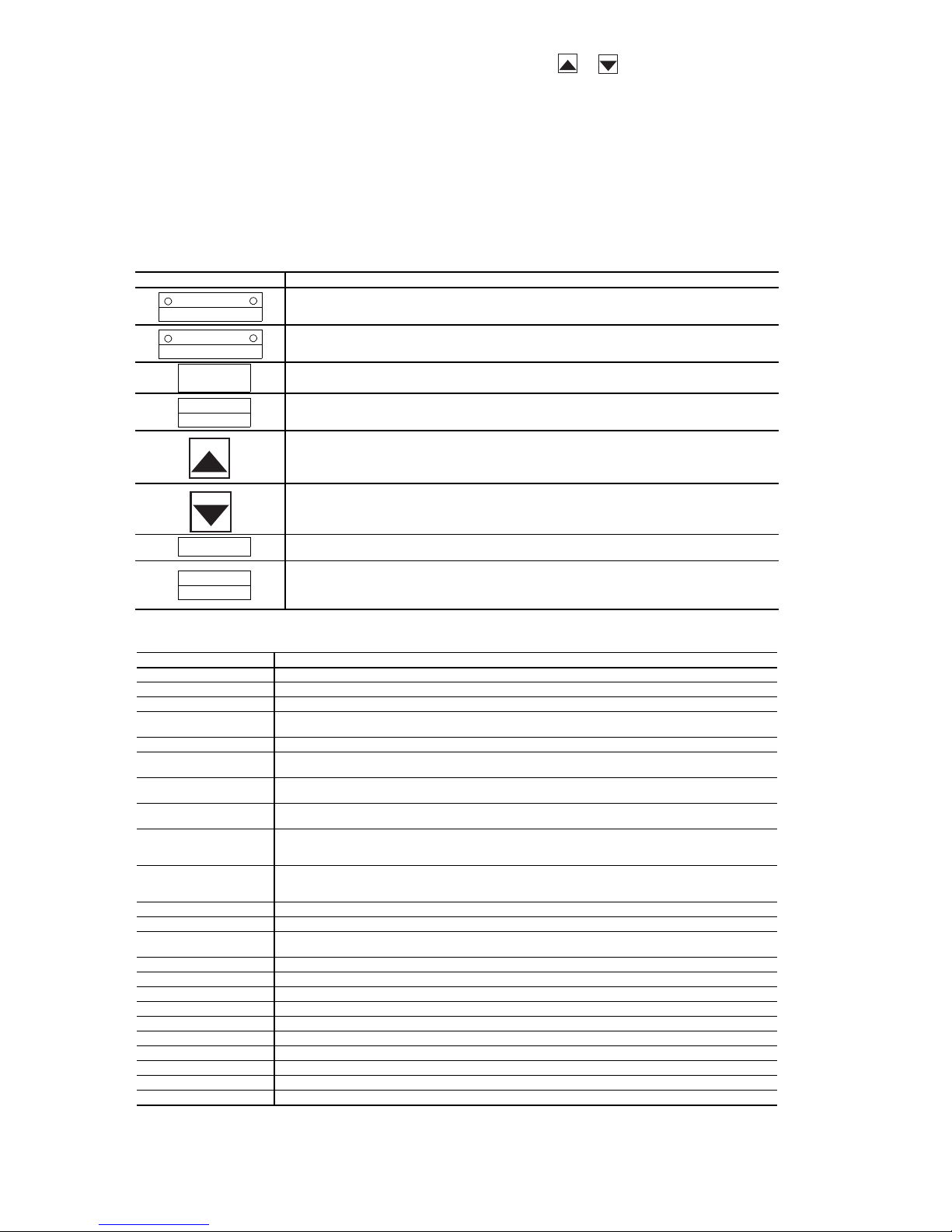
STATUS MONITOR MODE — In Status Monitor mode, it is
possible to monitor the VFD status (frequency command, output
voltage, current, terminal information, etc.). Status monitor
mode is entered by pressing the Setup/Program/Monitor key,
then selecting MON at the mode selection menu and pressing
the Read/Write key. Table 11 details the procedure for entering
status monitor mode (from standard monitor mode) and viewing
all the monitored status variables. The present output frequency
(which, just after power is applied, is 0.0) is displayed. (If the STCC terminals are not shorted, OFF will be displayed).
Table 11 — Keys and Functions for 50XJ VFD
If either or is pressed continuously, every 0.5 sec
the next/previous item will be displayed. As optional points,
RUN, STOP, displaying the frequency status, and switching to
local/remote and manual/auto modes can be performed.
MANUAL MODE — To override the automatic unit controls
and manually operate the fan from the VFD display, press keys
for “MANUAL” run mode, “LOCAL” speed control, and
press the Up or Down arrow keys to increase or decrease
output frequency.
KEY FUNCTION
LOCAL/REMOTE
SPEED CT RL
MANUAL/AUTO
RUN MODE
SETUP
PROGRAM
MONITOR
READ
WRITE
RUN
STOP
RESET
Local/Remote Key
Switches the source of frequency command information from panel/ter minal
block. The appropriate LED is lit to indicate local or remote frequency command.
Manual/Auto Key
Switches the source of run/stop command information from panel/terminal block.
The appropriate LED is lit to indicate manual or auto run/stop command.
Setup/Program/Monitor Key
Toggles between Setup, Program, Monitor, and Frequency Mode.
Read/Write Key
Mode, group, parameter, data, and frequency selection key. This key is used to
select or enter a parameter value, a frequency command, or a group name.
Up Key
Scrolls up the setting of the currently displayed parameter. If the key is held
down, the scrolling speed gradually increases. Only RAM values are changed.
Also toggles to other function group entries. Pushing Read/Write key saves the setting.
Down Key
Scrolls down the setting of the currently displayed parameter. If the key is held
down, the scrolling speed gradually increases. Only RAM values are changed.
Also toggles to other function group entries. Pushing Read/Write key saves the setting.
Run Key
This key is used to star t a RUN command (only valid when in manual control mode).
Stop/Reset Key
Functions as the STOP key and emergency stop key during local operation.
Functions as the RESET key when an inverter trip occurs. In all other modes,
emergency off is engaged when this key is pressed twice.
Table 12 — VFD Non-Trip Messages for 50XJ Unit
LED MESSAGE EXPLANATION
OFF Displayed whenever the ST-CC connection is open.
pOFF Displayed when the VFD control power supply voltage is too low.
nOFF Displayed when the VFD’s main DC bus voltage is low.
rtrY Auto-restart message: alter nately displayed with the output frequency whenever the
Err1 Displayed when 2 frequency points (F-P1,F-P2,etc.) are set too close to each other.
CLr Displayed during a pending clear command (after the STOP/RESET key has been
EOFF Displayed during a pending emergency off command (after the STOP/RESET key has
CtrL Displayed during a pending coast stop command (after the Local/Remote key has
HI This maximum value warning message “HI” will be alternately displayed in the data
LO This minimum value warning message “LO” will be alternately displayed in the data
PA SS Displayed if the correct password is entered at the password prompt.
Err Displayed if an incorrect password is entered at the password prompt.
E1 Displayed when the VFD attempts to display a number that exceeds four
db Displayed when DC injection braking is being executed.
dbon Displayed when motor shaft stationary control is being executed.
FJOG Displayed when in forward JOG mode.
rJOG Displayed when in reverse JOG mode.
L VFD/motor overload pre-alarm display.
C Overcurrent pre-alarm display.
P Overvoltage pre-alarm display.
H Overheat pre-alarm display.
t Option board communication alarm display.
InIt Displayed when the VFD is initializing values during resetting/power-up.
VFD tries to automatically restart after a non-critical trip.
pressed ONCE after a trip).
been pressed ONCE when in terminal control mode).
been pressed once when in local control mode while the VFD is running).
field of a parameter when an attempt is made to increase the setting value greater than
the parameter’s maximum value.
field of a parameter when an attempt is made to decrease the setting value less than
the parameter’s minimum value.
numerical digits.
20
Page 21

Table13—VFDTripMessagesfor50XJUnit
LED MESSAGE EXPLANATION
nErr Displayed in the trip history in standard monitor mode when no trip has been recorded
OC1 Overcurrent during acceleration trip
OC2 Overcurrent during deceleration trip
OC3 Overcurrent during normal (constant speed) run trip
OC1P Overcurrent in DC section during acceleration trip
OC2P Overcurrent in DC section during deceleration trip
OC3P Overcurrent in DC section during normal (constant speed) run trip
OCL Load end over current trip detected at start-up (output terminals, motor wiring, etc.)
OCA1 U-phase short circuit trip detected at start-up
OCA2 V-phase short circuit trip detected at start-up
OCA3 W-phase short circuit trip detected at start-up
OP1 Overvoltage during acceleration trip
OP2 Overvoltage during deceleration trip
OP3 Overvoltage during normal (constant speed) run trip
OLIn VFD overloaded trip
OLnt Motor overloaded trip
OCr Dynamic braking resistor overcurrent trip
OLr Dynamic braking resistor overload trip
OH Inverter overheat trip
E Emergency off trip message. Displayed after the STOP/RESET key has been pressed
EEP1 EEPROM failure during write cycle
EEP2 EEPROM abnormality during initial reading
Err2 RAM error
Err3 ROM error
Err4 CPU error
Err5 Communication interruption error
Err6 Gate array error
Err7 Output current detection circuit error
Err8 Option PCB error trip
Err9 Option ROM error
UC Low operating current trip
UP1 Main circuit undervoltage trip
Ot Overtorque trip
EF1 Software detected earth fault trip
EF2 Hardware detected earth fault trip
Etn Auto-tuning error
EtYP Inverter typeform and EEPROM typeform mismatch error
dANP Damper trip. When damper function is selected, and damper is closed while the motor
LOSS IV analog input loss. Valid when LA15 = 3 and frequency command is selected from
LEGEND
CPU — Central Processing Unit
IV — Analog Input Terminal
PCB — Printed Circuit Board
RAM — Random Access Memor y
ROM — Read-Only Memory
U-phase — Phase 1 Output (T1)
V-p hase — Phase 2 Output (T2)
W-phase — Phase 3 Output (T3)
since the last VFD reset or trip clear.
once when in Auto Control mode, or press STOP/RESET key twice within one second
in Manual control mode.
is running.
IV analog input terminal.
21
Page 22

Table 14 — VFD Mode Summary for 50XJ Unit
KEY OPERATON LED MESSAGE EXPLANATION
— 0.0 Standard monitor mode
S/P/M SEtP Switch to mode selection menu.
S/P/M PrG Program mode.
S/P/M non Select Status Monitor mode title with U/D keys.
R/W Fr-F Enter Status Monitor mode by pressing R/W. First monitor
DOWN 60.0 Pressing UP/DOWN views next/previous status variable.
DOWN C 0 Load current (%) monitor (monitor #2)
DOWN Y 228 Input voltage (V) monitor (monitor #3)
DOWN P 0 Output voltage (V) monitor (monitor #4)
DOWN A.... Input terminal status monitor
DOWN b.... Input terminal status monitor
DOWN O.... Output terminal status monitor
DOWN t0.00 Total RUN time monitor
DOWN OC1 Past trip #1 monitor
DOWN OC2 Past trip #2 monitor
DOWN OC3 Past trip #3 monitor
DOWN nErr Past trip #4 monitor
DOWN Fr-F Return to the top menu item
item (motor run direction) is displayed.
Frequency command value displayed (monitor #1)
50BV Variable Frequency Drive Control — The
variable frequency drive is factory wired and programmed for
proper operation with the unit controls; no installation or
service adjustments are normally required.
The VFD default conditions at unit power up are: “0.0 Hz”
in the LED display. When the fan is operating, the LED
displays the output frequency in Hz.
OPERATING KEYPAD — The keypad allows users to enable or disable the keypad, input commands from the keypad,
and monitor drive operation. Fig. 7 shows the operating panel
keypad layout and the locations of the keys and display LEDs.
The 4-character LED displays various values, depending
upon what mode is running.
• In Standard Monitor mode: the LED displays the current
output frequency.
• In Status Monitor mode: monitors the status conditions
and frequency command value setting.
• In Setup mode: displays setup parameter titles and values.
• During a trip: displays the trip title.
The appropriate local/remote LED, which is inset into the
speed control key, is lit when the unit is in local or remote
mode.
KEY FUNCTIONS — Refer to Fig. 8 for the functions of
each key on the keypad.
NON-TRIP MESSAGES — Non-trip messages are those that
may be displayed but do not cause a trip and are not recorded in
the fault history. Table 15 lists the non-trip messages with their
explanations.
TRIP MESSAGES — Trip messages and their causes are
shown in Table 16.
CLEARING A TRIP — A trip clear can be performed after
the cause of the trip has been removed. To perform a trip clear,
either switch off power to the inverter (keep VFD off until
charge LED turns off) or use the following procedure:
Press STOP. The display will show: CLr. Press STOP again.
The display will show: 0.0, indicating that the trip is cleared
and the display will return to Standard Monitor mode.
If any key other than the STOP key is pressed at the trip
clear command prompt, the trip clear command is aborted and
the display returns to Standard Monitor mode (where the trip
title will be displayed flashing). The trip clear command does
not clear the recorded past faults.
STATUS MONITOR MODE — In Status Monitor mode, it is
possible to monitor the inverter status (frequency command,
output voltage, current, terminal information, etc.). Status
monitor mode is entered by pressing the MON key until the
monitor LED is lit. The present output frequency (which, just
after power is applied, is 0.0) is displayed. (If the ST-CC
terminals are not shorted, OFF will be displayed.)
If either or is pressed continuously, every 0.5 sec
the next/previous item will be displayed. As optional points,
RUN, STOP, displaying the frequency status, and switching to
local/remote and manual/auto modes can be performed.
22
Page 23

VEC lamp
Lights when sensorless
vector operation control
is running.
ECN lamp
Lights when
mode is in
Indicates that high voltage is
still present within the inverter.
Do not open the terminal
board cover while this is lit.
Pressing up or down
key when this lamp
is lit allows the
setting of operation
frequency.
energy-saving
operation.
Charge Lamp
Up/down key lamp
RUN key lamp
Lights when the
RUN key is
enabled.
RUN lamp
Lights when the inverter is
operating. Blinks when the
automatic acceleration/deceleration
is operating
CHARGE
MON ENT
RUN STOP
RUN key
Pressing this key
while the RUN key
lamp is lighted
starts operations.
Fig. 7 — 50BV VFD Display
MON lamp
Lights when the
inverter is in
monitor mode.
STOP key
Everypressingofthiskey
while the RUN key lamp is
lit will cause a slowdown
stop.
PRG lamp
Lights when the inverter is
in parameter setting mode.
Monitor key
Displays operation
frequency, parameters,
and error causes.
Built-in
potentiometer lamp
Built-in potentiometer
Operation frequency can
be changed when the
built-in potentiometer lamp
is lit.
Enter key
Down key
Up key
ALL OF THE BASIC PARAMETERS CAN BE SET BY THE SAME
STEP PROCEDURES.
[STEPS IN KEY ENTRY FOR BASIC PARAMETERS]
MON
ENT
ENT
SWITCHES TO THE SETTING MONITOR MODE.
SELECTS PARAMETER TO BE CHANGED.
READS THE PROGRAMMED PARAMETER
SETTING.
CHANGES THE PARAMETER SETTING.
SAVES THE CHANGED VALUE OF THE
PARAMETER SETTING.
Fig. 8 — 50BV VFD Display Function Keys
23
Page 24

Table 15 — Non-Trip Messages for the 50BV VFD
ERROR
CODE
OFF (Note 1) ST terminal OFF • The ST-CC circuit is opened. • Close the ST-CC circuit.
NOFF Undervoltage in main
rtrY Retry in process • The inverter is in the process of retry.
Err1 Frequency point
CLr Clear command
EOFF Emergency stop
HI/LO Setting error alarm /
db DC braking • DC braking in process • Normal if the message disappears after
In It Parameters in the
Atn Auto-tuning in process • Auto-tuning is in process. • Normal if the message disappears after
NOTES:
1. ST : Terminal of stand by function.
2. When the ON/OFF function is selected for DC braking (DB), using the input terminal selection parameter, you can judge
the inverter to be normal if “db” disappears when opening the circuit between the terminal and CC.
PROBLEM POSSIBLE CAUSES REMEDIES
circuit
setting error
acceptable
command acceptable
An error code and
data are displayed
alternately twice each.
process of initialization
Setup parameters in
the process of being set
• The supply voltage between R, S and T is
under voltage.
• A momentary stop occurred.
• The frequency setting signals at points 1
and 2 are set too close to each other.
• This message is displayed when pressing
the STOP key while an error code is displayed.
• The operation panel is used to stop the
operation in automatic control or remote
control mode.
• An error is found in a setting when data is
reading or writing.
• Parameters are being initialized to default
values.
• Setup parameters are in the process of
being set.
• Measure the main circuit supply voltage.
If the voltage is at a normal level, the
inverter requires repairing.
• The inverter is normal if it restarts after
several tens of seconds.
The inverter restarts automatically. Be careful of the
machine because it may suddenly restart.
• Set the frequency setting signals at points
1 and 2 apart from each other.
• Press the STOP key again to clear the
trip.
• Press the STOP key for an emergency stop.
To cancel the emergency stop, press any other key.
• Check whether the setting is made
correctly.
several tens of seconds. (See Note 2.)
• Normal if the message disappears after a
while (several seconds to several tens of seconds).
• Normal if the message disappears after a
while (several seconds to several tens of seconds).
several seconds.
Table 16 — Trip Messages for 50BV VFD
ERROR
CODE
OC1 1 Overcurrent during
OC2 2 Overcurrent during
OC3 3 Overcurrent during
OCR 5 Arm overcurrent at
OCL 4 Overcurrent (An
OP1 A Overvoltage during
OP2 B Overvoltage during
COMMUNICATION
NO.
PROBLEM POSSIBLE CAUSES REMEDIES
acceleration
deceleration
operation
start-up
overcurrent on the
load side at start-up)
acceleration
deceleration
• The acceleration time ACC is too short.
• The V/F setting is improper.
• A restart signal is input to the rotating
motor after a momentary stop, etc.
• A special motor (e.g. motor with a small
impedance) is used.
• The deceleration time dEC is too short.
(During deceleration)
• The load fluctuates abruptly.
• The load is in an abnormal condition.
• A main circuit element is defective. • Make a service call.
• The insulation of the output main circuit or
motor is defective.
• The motor has too small impedance.
• The input voltage fluctuates abnormally.
(1) The power supply has a capacity of
200kVA or more.
(2) A power factor improvement capacitor is
opened or closed.
(3) A system using a thyristor is connected
to the same power distribution line.
• A restart signal is input to the rotating
motor after a momentary stop, etc.
• The deceleration time dEC is too short.
(Regenerative energy is too large.)
• F304 (dynamic braking resistor
activation) is off.
• F305 (overvoltage limit operation) is off.
(1) The input voltage fluctuates abnormally.
The power supply has a capacity of
200kVA or more.
(2) A power factor improvement capacitor is
opened or closed.
(3) A system using a thyristor is connected
to the same power distribution line.
• Increase the acceleration time ACC.
• Check the V/F parameter.
• Use F301 (auto-restart) and F302
(ride-through control).
• Increase the carrier frequency F300.
• Increase the deceleration time dEC.
• Reduce the load fluctuation.
• Check the load (operated machine).
• Check the cables and wires for defective
insulation.
• Insert a suitable input reactor.
• Use F301 (auto-restart) and F302
(ride-through control).
• Increase the deceleration time dEC.
• Install a suitable dynamic braking resistor.
• Enable F304 (dynamic braking selection).
• Enable F305 (overvoltage limit operation).
• Insert a suitable input reactor.
24
Page 25

Table 16 — Trip Messages for 50BV VFD (cont)
ERROR
CODE
*EPHO 9 Output phase failure • A phase failure occurred in the output line
*EPH1 8 Input phase failure • A phase failure occurred in the input line
OH2 2Eh External thermal trip • A thermal trip command is entered from
*UP1 1E Undervoltage trip
COMMUNICATION
NO.
OP3 C Overvoltage during
OL1 D Inverter overload • The acceleration ACC time is too short.
OL2 E Motor overload • The V/F setting is improper.
*Ot 20h Over-torque trip • The load torque rises up to the over-torque
OLr F Dynamic braking
OH 10h Overheat • The cooling fan does not rotate.
PROBLEM POSSIBLE CAUSES REMEDIES
constant-speed
operation
resistor overload trip
(main circuit)
• The input voltage fluctuates abnormally.
(1) The power supply has a capacity of
200kVA or more.
(2) A power factor improvement capacitor is
opened or closed.
(3) A system using a thyristor is connected
to the same power distribution line.
• The motor is in a regenerative state
because the load causes the motor to run at
a frequency higher than the inverter
output frequency.
• The DC braking amount is too large.
• The V/F setting is improper.
• A restart signal is input to the rotating
motor after a momentary stop, etc.
• The load is too large.
• The motor is locked up.
• Low-speed operation is performed
continuously.
• An excessive load is applied to the motor
during operation.
of the main circuit.
of the main circuit.
an external input device.
detection level during operation
• The deceleration time is too short.
• The dynamic braking amount is too large.
• The ambient temperature is too high.
• The vent is blocked up.
• A heat generating device is installed close
to the inverter.
• The thermistor in the unit is broken.
• The input voltage (in the main circuit) is
too low.
• Insert a suitable input reactor.
• Install a dynamic braking resistor.
• Increase the acceleration time ACC.
• Reduce the DC braking amount F251
and the DC braking time F252.
• Check the V/F parameter setting.
• Use F301 (auto-restart) and F302
(ride-through control).
• Use an inverter with a larger rating.
• Check the V/F parameter setting.
• Check the load (operated machine).
• Adjust OLN to the overload that the
motor can withstand during operation in a
low speed range.
• Check the main circuit output line, motor,
etc., for phase failure.
• Enable F605 (Output phase failure
detection).
• Check the main circuit input line for phase
failure.
• Enable F608 (input phase failure
detection).
• Check the external input device.
• Enable F615 (Over-torque trip selection)
• Check whether the system is in a normal
condition.
• Increase the deceleration time dEC.
• Use a dynamic resistor with a larger
capacity (W) and adjust F308 (PBR
capacity parameter) accordingly.
• Restart the operation by resetting the
inverter after it has cooled down enough.
• The fan requires replacement if it does
not rotate during operation.
• Secure sufficient space around the
inverter.
• Do not place any heat-generating device
near the inverter.
•Makeaservicecall.
• Check the input voltage.
• Enable F627 (undervoltage trip
selection).
• To cope with a momentary stop due to
undervoltage, enable F302 (ride-through
control) and F301 (auto-restart).
25
Page 26

Table 16 — Trip Messages for 50BV VFD (cont)
ERROR
CODE
EtYP 29h Inverter type error • The control circuit board (main circuit
EEP1 12h EEPROM fault • A data writing error occurs. • Turn off the inverter, then turn it on again.
*With a parameter, you can choose between trip-on and -off.
NOTES:
1. During operation, the following alarms may be displayed, which have the same meaning as previously defined alarms.
2. If two or more problems arise simultaneously, one of the following alarms appears and blinks.
COMMUNICATION
NO.
*UC 1D Small-current
EF2 22h Ground fault trip • A ground fault occurs in the output cable
E 11h Emergency stop • During automatic operation or remote
Err2 15h Main unit RAM fault • The control RAM is defective. • Make a service call.
Err3 16h Main unit ROM fault • The control ROM is defective. • Make a service call.
Err4 17h CPU fault trip • The control CPU is defective. • Make a service call.
Err5 18h Remote control
Etn 28h Auto-tuning error • Check the settings of the motor parameters F401to F408
• C (overcurrent alarm) — same as OC
• P (overvoltage alarm) — same as OP
• L (overload alarm) — same as OL1/OL2
• H (overheat alarm) — same as OH
CP, PL, CPL
The blinking alarms, C, P, L, H are displayed in this order from left to right.
PROBLEM POSSIBLE CAUSES REMEDIES
operation trip
error
• The output current falls to the low-current
detection level during operation.
or the motor.
operation, a stop command is entered from
the operation panel or a remote input device.
• An error arises during remote operation. • Check the remote control device,
board or drive circuit board) is replaced.
• Check that the motor is not two or more sizes smaller in capacity than the inverter.
• Check that the inverter output cable is not too thin.
• Check that the motor is not running.
• Check that the motor is a three-phase inductive motor.
• Enable F610 (low-current detection
parameter).
• Check whether the detection level is set
properly to the system.
(F611 and F612)
• If no error is found in the setting, make a
service call.
• Check the cable and the motor for ground
faults.
• Reset the inverter.
cables, etc.
• Make a service call.
If it does not recover from the error, make
a service call.
26
Page 27

TROUBLESHOOTING
Refer to Tables 17-21 for troubleshooting information.
Run Test Troubleshooting — The automatic run test
is a diagnostic tool used during unit start-up. Table 17
describes troubleshooting specifically for the automated run
test.
Table 17 — Run Test Troubleshooting
PROBLEM POSSIBLE CAUSE
Control modules do not have lights when unit power on. Transformer open. Circuit breaker open. Power wiring open. Module failure.
Control display does not light up when unit power on. Connection location. Interface cable open. Display failure.
Run test will not start. Pre-existing ALARM (red)? Not “Logged in” with password.
WARN (yel) does not light during run test. Wiring open. Lamp failure. Control module failure.
ALARM (red) does not light during run test. Wiring open. Lamp open. Control module failure.
Run test stops, ALARM (red) light is lit after it blinks once. Bypass switch to LINE. Mode switch to OFF. Duct high
Fan does not start/ALARM (red) blinks 2 times. Fan relay failure.
Run test stop, ALARM (red) light is lit after blinking 3 times. Wiring open. VFD connection error. VFD setup error. Fan relay failure.
Run test stop, ALARM (red) is lit after it blinks 4 times.
Fan does not increase speed.
Fan does not stop after ALARM (red) blinks 5 times. Fan relay failure.
Fan rotation is backwards. VFD to motor wiring sequence error. VFD setup error.
Run test stop, ALARM (red) is lit after blinking 6 times.
Compressor 1 does not star t.
Run test stop, ALARM (red) is lit after blinking 7 times.
Compressor 2 does not star t.
Run test stop, ALARM (red) is lit after blinking 8 times.
Compressor 3 does not star t.
Run test stop, ALARM (red) is lit after blinking 9 times.
Compressor 4 does not star t.
Compressor rotation is backwards. Field power wiring sequence error. Compressor power wiring sequence error.
“C” message in I/O status display. No input signal/communication failure.
“Service” message in I/O status display. Value is forced from 6400 keypad entry.
“Supervisor” message in I/O status display. Value is forced from network communication (i.e., PC).
ALARM (red) always on, will not enter run test. SAT, DSP, CSMUX, DHS, or PHASE input values out of range. Mode switch OFF.
Switch not in Local.
pressure switch open. Fire shutdown input or jumper open.
Supply air temp out of range. Duct static pressure sensor out of range.
Compressor resistor board wiring error or failure.
Current isolator failure. Control module failure.
VFD connection error. VFD setup error.
Current isolator load adjustment too low.
Wiring open. Compressor resistor board wiring error or failure.
High-pressure switch, low-pressure switch, coil frost switch,
or compressor protection module open. Compressor relay failure.
Contactor failure. Control module failure. No refrigerant charge.
Wiring open. Compressor resistor board wiring error or failure.
High-pressure switch, low-pressure switch, coil frost switch,
or compressor protection module open. Compressor relay failure.
Contactor failure. Control module failure. No refrigerant charge.
Wiring open. Compressor resistor board wiring error or failure.
High-pressure switch, low-pressure switch, coil frost switch,
or compressor protection module open. Compressor relay failure.
Contactor failure. Control module failure. No refrigerant charge.
Wiring open. Compressor resistor board wiring error or failure.
High-pressure switch, low-pressure switch, coil frost switch,
or compressor protection module open. Compressor relay failure.
Contactor failure. Control module failure. No refrigerant charge.
Forcing and Clearing an Input or Output — Dur-
ing unit operation and/or troubleshooting, it may be necessary
or desirable to clear an input or output. Tables 18 and 19
describe the procedure for clearing inputs and outputs.
STEP # INSTRUCTION/ACTION RESULT
1. Press 3, SET, ENTER “Controller Password”
2. Press ENTER “Log in to Controller” “Enter Password”
3. Press 1111, ENTER “Log in to Controller” “Logged in”
4. Press STAT “Hardware Points”
5. Press ENTER “Supply Air Temperature”
6. Press down arrow to obtain desired item (NOTE: order is PCB1 I/O, PCB2 I/O, PCB3 I/O)
7. Key in force value (1=on/start, 0 = off/stop), ENTER force value/status “Service”
STEP # INSTRUCTION/ACTION RESULT
1. Press 3, SET, ENTER “Controller Password”
2. Press ENTER “Log in to Controller” “Enter Password”
3. Press 1111, ENTER “Log in to Controller” “Logged in”
4. Press STAT “Hardware Points”
5. Press ENTER “Supply Air Temperature”
6. Press down arrow to obtain desired item (NOTE: order is PCB1 I/O, PCB2 I/O, PCB3 I/O)
7. Press CLEAR, ENTER auto value/status (NOTE “Service” must be gone)
Table 18 — Forcing an Input or Output
Table 19 — Clearing a Forced Input or Output
27
Page 28

Table 20 — Alarms Displayed at Unit LID
FUNCTION ALARM MESSAGE (Actual Text) CAUSE UNIT RESPONSE (See Notes) RESET
SAT
DSP_ALM
FSD Fire Shutdown External Fire Alarm input opens for 5 sec. Unit shuts down, indicates alarm Automatic
DHS
CSMUX
CDWF
FLTS
FREEZ
C1_ALM
C2_ALM
C3_ALM
C4_ALM
SFS
EWT
MA_RA
PHASE
BYPAS
NOTES:
1. Unit display will indicate alarm by displaying “There is 1 Alarm” or
“There are X alarms”, for the active alarms in the controller.
2. Red light on, indicating alarm.
3. Yellow light is on, indicating a warning.
SATxx.xdFoutside
limit of xxx.x dF
Duct Static Sensor Failure Duct Pressure Sensor reading is out of
Duct High Static Pressure Pressure rises above 3.0 in.H2O during
CSMUX x.xx Volts outside
limit of x.xx Volts
Check Condenser Water Flow Waterflow Switch contacts are open at startup,
Change Filters Filter pressure drop exceeds Filter Pressure
Economizer Freeze Condition Economizer Freeze Switch contacts for 5 sec.
Compressor 1 Fault
Compressor 2 Fault
Compressor 3 Fault
Compressor 4 Fault
Check Supply Fan Duct Pressure Sensor reading is below .3 in.
EWT xx.x dF outside
limit of xxx.x dF
MA_RA xx.x dF outside
limit of xxx.x dF
Phase Loss Phase monitor activates (see “Phase
SAT reads out of prescribed range
for 5 sec. during operation
range (i.e., likely faulty sensor or circuit).
operation. Set point adjustable on the switch.
Used for Off position of switch on smaller
units with one controller
Compressor safety circuit Resistor Board
reads out of prescribed range for 5 sec.
during operation
or go open for 5 sec. during operation.
Switch setting (and contacts open) for 5 sec.
open during operation.
Compressor safety circuit opens for 2 sec. Unit shuts that compressor down,
H2O at 10 sec. after starting fan, or during
operation, or
supposed to be Off.
EWT reads out of prescribed range for 5 sec.
or more
ma_ra reads out of prescribed range for 5 sec.
or more
Loss/Reversal Protection Switch” on page 5)
for 5 sec. during operation.
BYPAS switch in Bypass position or Off,
local remote in Off position
reads above .3″ when fan is
Unit shuts down and
indicates alarm
Unit shuts down, indicates alarm Automatic
Unit shuts down, indicates alarm Automatic
Unit shuts down and indicates
alarm
Compressor Cooling shuts down,
locks out and indicates warning
Unit operates normally,
but still indicates Warning
Warning indicated for 15 minutes
turns off ventilation request, then
unit shuts down and Econo valve
opens, pump request stays on,
and Alarm indicated
and indicates Warning, but retries
2 more times before locking it out.
If on but indicates off cooling,
and heating will be disabled
warning light will be on
Indicates warning Automatic
Indicates warning Automatic
Unit shuts down, indicates alarm Automatic
Automatic
Automatic
Automatic
Automatic
Automatic
Automatic
Automatic
Standard Diagnostic Features, Alarm and
Warning Lights
SUPPLY AIR TEMPERATURE SENSOR FAILURE — If
the supply air temperature sensor fails and indicates either
245 F from a short or -40.0 F from and open sensor the controller outputs will be forced to off with safety forces, the alarm
output will close and the red Alarm light will be lit. A system
alarm will be generated and displayed on the unit keypad. Unit
reset is automatic when the supply air sensor has a valid
reading again.
DUCT STATIC PRESSURE SENSOR FAILURE — If the
duct static pressure sensor fails and indicates either 5.0 inches
from a short or 0.0 inches from and open sensor the controller
outputs will be forced to off with safety forces, the alarm
output will close and the red Alarm light will be lit. A system
alarm will be generated and displayed on the unit keypad. Unit
reset is automatic when the supply air sensor has a valid
reading again.
FIRE/SHUTDOWN INPUT (FSD) — This is a normally
closed input, which when opened, deenergizes an isolation
relay in the unit, opening the input to the controller. When this
input turns opens, all control outputs are immediately turned
off, including the fan. Fire forces will be displayed on the
outputs. Unit reset is automatic when the FSD input is closed
again. A system alarm will be generated and displayed at the
keypad.
DUCT HIGH STATIC INPUT (DHS) — This air switch
provides over pressurization protection for the ductwork. It is
factory installed in the unit. The switch is a normally open
switch, with adjustable manual setting (range is 1 to 5 in. wg
default setting is 3.0 in. wg). Upon switch closure, the controller outputs will be forced to off with safety forces, the alarm
output will close and the red Alarm light will be lit. A system
alarm will be generated and displayed on the unit keypad. Unit
reset is automatic when the duct pressure is again below the
switch setting minus the device hysteresis.
COMPRESSOR MULTIPLEX (MUX) BOARD — A resistance board is used to generate a variable voltage input to the
controller to determine compressor status. If the voltage output
from this board gets out of the acceptable range the controller
outputs will be forced to off with safety forces, the alarm
output will close and the red Alarm light will be lit. A system
alarm will be generated and displayed on the unit keypad. Unit
reset is automatic when the Mux board has a valid reading
again. The valid range is between 1.5 and 10 vdc. The table
below indicates what voltages correspond to the compressor
status indicated in the controller.
28
Page 29

Table 21 — Compressor MUX Board Voltages
COMP VOLTS RANGE
None 1.86 1.50 < V < .95
1 2.88 last val < = V < 2.95
2 3.59 last val < = V < 3.68
1,2 4.44 last val < = V < 4.55
3 5.13 last val < = V < 5.25
45.71
1,3 5.85 last val < = V < 5.99
1,4 6.39
2,3 6.36 last val < = V < 6.54
2,4 6.87
1,2,3 6.99 last val < = V < 7.15
1,2,4 7.46 last val < = V < 7.63
3,4 7.94 last val < = V < 8.11
1,3,4 8.45 last val < = V < 8.58
2,3,4 8.81 last val < = V < 8.99
1,2,3,4 9.26 V > 8.99
last val < = V < 5.85
and CMP4 is on
last val < = V < 6.51
and CMP4 is on
last val < = V < 7.03
and CMP4 is on
CONDENSER WATER FLOW — This is an optional
switch that can be used with the OMNIZONE™ controller. A
thermal dispersion flow switch detects water flowing past the
sensor element and closes normally open contacts that energize
a relay with normally open contacts to the unit controller. If no
flow switch is installed, a jumper must be in place to indicate
that there is water flow all the time in order for the economizer
and compressors to operate. A configuration decision is used to
indicate if a flow switch is installed and disable alarms from the
flow switch. When the flow switch is installed, the controller
will check for water flow when flow is requested for unit
operation. The controller will also test or to see if there is water
flow when the unit is not operating. If there is no flow when
the unit is operating or if there is flow when the unit is not
operating, the warning relay will energize and the yellow light
will be lit. If only loss of flow indication is desired, the
configuration for the flow switch may be set to no and the
controller will only energize the warning relay and turn on the
yellow light if there is a loss of flow while the unit is in
operation.
DIRTY FILTERS INPUT — This air pressure delta switch is
factory installed in the 50XJ unit. It receives 5 vdc from the
unit controller and monitors air pressure delta across the return
air filters. Switch is normally open, with manually adjustable
setting at the switch between 0.5 to 1.5 in. wg. Upon closure,
controller should wait to assure closure for minimum 1 minute,
and then indicate an alarm both via its Alarm Output and via
communications. However, all other unit operation should
remain normal.
A phase loss reversal switch may be installed in the unit to
detect over, under voltage conditions and phase loss or reversal.
Upon switch opening, the controller outputs will be forced to off
with safety forces, the alarm output will close and the red Alarm
light will be lit. A system alarm will be generated and displayed
on the unit keypad. Unit reset is automatic when the voltage and
power phases have been restored.
ECONOMIZER COIL FREEZE PROTECTION SWITCH —
This switch is installed in the 50XJ unit when the economizer
coil is provided. In the event the freeze protection switch
contacts open, the ventilation request output will be closed for
15 minutes and the Warning light will light. If the freeze
protection switch contacts are still open after 15 minutes, the
supply fan will be stopped, all compressor cooling will stop,
the economizer valve will open to 100%, the pump request
output will remain on, and the Alarm light will light. This will
maintain condenser water flow through the coil to prevent
freezing the coil while stopping all other operations that could
have contributed or will be affected by the freeze condition.
Unit reset is automatic when the contacts on the freeze
protection switch close again. The contacts on the freeze
protection switch open below 37 F.
SUPPLY FAN STATUS — Supply fan status is determined
by the duct static pressure sensor. If the fan is operating and a
fan speed signal is sent to the variable frequency drive, the duct
static pressure must become greater than the supply fan status
high set point (SETPT01) for the supply fan status software
point to turn on. When the duct static pressure becomes lower
than the supply fan status low set point, the supply fan status
will indicate OFF. If at any time the commanded state of the
supply fan does not agree with the supply fan status for more
than a minute, a supply fan status warning will be issued and
the warning light will be lit.
COMPRESSOR STATUS — Compressor status is determined
from the compressor MUX voltage input to the OMNIZONE
controller. If at any time the compressor status indicates off for
more than 30 seconds when the compressor commanded state
is on, the compressor will be turned off with a safety force and
the controller will try to start the compressor after five minutes.
If the compressor status does not indicate on for more than
30 seconds then the compressor will be turned off again with a
safety force for ten minutes. The controller will then try to
restart the compressor a second time. If the compressor status
does not come on within 30 seconds the compressor will be
turned off for 15-minutes this time. After the 15-minute delay
the controller will try to restart the compressor for a third time.
If the compressor does not start it will be locked out for this
operating cycle and will not be restarted until the OMNIZONE
controller goes through an off cycle where the cooling and
supply fan are shut down. When the compressor is going
through the three restarts or when it is locked out the Warning
light will be lit and the specific compressor alarm will be
indicated on the display and via communications. The three
strikes compressor test is reset automatically if the compressor
status comes on while the compressor is on.
29
Page 30

CBR
TRANS-1 (24VAC)
UNIT WIRING
WIRE LEGEND
1010
10
11
YELBLU
11
S9
FIELD WIRING
10
CDWF
A B
237
TB1-2
CDWFS
Factory Jumper
TB1-1
DIS-2
RED
B
+-
A
DIS-1
144
FNOD = 0
CNOD = 0
CC
F201 = 20
S9
F103 = 0
CNOD = 0
YEL
ALARM
F103=0
II
FNSL = 2
F114 = 1
FNOD = 0
B
A
DIS-3 DIS-4
143
APPENDIX A — WIRING DIAGRAMS
VFD2
F114 = 1
F
S1
CC
COMMON TB
10
COMMON (C)
VFD
DISPLAY
10
10
10
VFD1
FM
RC
RY
R
S1
P24
VFD-P24
139
IN OUT
11
VFD-S1
140
5 3
SPEED
10
142
SF
CC
OPTIONAL
BYPAS
Open
Close
24VAC
CC
VIA
VFD-CC
VFD-VIA
141
138
CC
VIA
P24
-
+
-
WARN
+
3 12
ECONO MBV
SF
+ -
AB
4
1
MBVR
7
TRANS-3 R
TRANS-3 C
RATAQUA
MBVR
AB
137
136
135
CMP2
AB
130
CLO2-3
3 +
2 -
VIO ORG
CLO2-2
129
CMP1
CLO1-3
CLO1-2
BLU
1
LOGIC
CLO2
BA
128
ORG
2 3 + -
VIO
CLO2-1
127
BLU
LOGIC 1
CLO1
DSP+
116
CLO1-1
V
115 115
BLU
TRANS-3 (24VAC)
CBR
YEL
121
114
C
T1 T2
CMP4
46
120
4
CSMUX
EWT
113
BLU
M2M1
BLK
BLK
ORG ORG
122
53
11
CMP2
CMP3
64
64
119
118
DHS2
DHS1
111
112
OLR1 CC1
HPS1LPS1
CMP1
6 4
117
132
DHS
53
110
T1 T2
CMP1
S
ROCC
109
BLU
M2
ORG ORG B LK BLK
123
3 M1
5
5
3
108
CC2
OLR2
CMP2
24VAC (R)
CDWF
107
LPS2 HPS2
53
106
TB2
FIELD CONN
OPTIONAL
9 10
BYPAS
126
53
BPS-S
FSD
105
SAT
219
102
101
MODE
218
219
AB
11
DSP
104
ROCC
10
SW
LOCAL
RED
DIS-5
ROCC
+
C
216
BA
DSP-
103
ALARM
WARN
ALM-CM
FSD
216
215
214
213
35
5 3
DIS-C
WARN
ALARM
BLU
REMOTE
OFF
DIS-111
FSD
-
50BVJ,K Low Voltage Schematic
102
101
NOTES:
SEE W/D NUMBER CNTL0038C-EM FOR HIGH VOLTAGE WIRING.
SEE W/D NUMBER CNTL0038D FOR LEGEND.
JUMPER INSTALLED FOR THIS DEVICE WHEN NOT SUPPLIED
1
2163
J1
141312
15
10
11
0
1
INT
EXT
7
9
8
J4
20MA
J6
DISPLAY
TO SYSTEM
PCB1
12345678
SW1
SW2
12345678
12345678
SW3
546
10VDC
OTHER
12345678
SW4
OTHER
213
18
AO
DO
1234
SW5
30
15
16
17
DO
AO
1234
SW6
14
131211
J3
867
9
10
5
J7
1
243
231
TO PCB2 (J7)
Page 31

UNIT WIRING
FIELD WIRING
WIRE LEGEND
PCB1 (J1-3)
COMMON TBLK
PCB2 (J1-3)
COMMON TBLK
CMP 1&2
CMP 1&2
COMPR 1
CLO1
CURRENT LOOP
CC1
L1
TRANS-2
CBR
CBR
TRANS-1
L1
L3
COMPR2
CLO2
CURRENT LOOP
T2
T2T3T1
L3
L2
T1
CC2
L1L2L3 T3
BM
BR
CBR
T1
L1
TRANS-3
T3
T2
L3
L2
BM
BR
TRANFORMER PRIMARY LEAD CLR:
T1
L1
- RED
208
- ORG
240
T2
L2
- PUR OR YEL
380
- BLK/RED460
-GRY
575
T3
L3
50BVJ,K High Voltage Schematic
L1 L2 L3 GND
T2
T3
T1
6
5
4
PHASE
BYPASS )
L3
L1
L2
GND
3
2
1
L3L1L2
W
V
U
E
T
R S
VFD
NOTES:
SEE W/D NUMBER CNTL0038A-EM FOR PCB1 LOW VOLTAGE WIRING.
SEE W/D NUMBER CNTL0038B FOR PCB2 LOW VOLTAGE WIRING.
SEE W/D NUMBER CNTL0038D FOR LEGEND.
31
Page 32

WIRE LEGEND
1010
YELBLU
CBR
TRANS-1 (24VAC)
UNIT WIRING
FIELD WIRING
10
10
A B
237
TB1-2
CDWFS
TB1-1
11
11
Factory Jumper
DIS-2
RED
DIS-1
CDWF
B
A
144
F103 = 0
FNOD = 0
CNOD = 0
S9
CC
FNSL = 2
F201 = 20
S9
F103 = 0
F114=1
FNOD = 0
CNOD = 0
YEL
B
A
DIS-3 DIS-4
ALARM
+-
143
MBVR
10
ECONO MBV
41
BLU
24VAC
Close
312
Open
BLU
BLU
COMMON (C)
TB2
FIELD CONN
102
BLU
SAT
ROCC
10
219
101
BLU
ALARM
WARN
ALM-CM
FSD
C
216
215
214
213
35
5 3
AQUA
F114 = 1
VFD2
R
A
B
7
II
F
S1
CC
COMMON TB
VFD
DISPLAY
MBVR RAT
TRANS-3 C
10
BLU
VFD1
FM
RC
RY
R
VIA
VFD-VIA
138
VIA
P24
+
136
P24
VFD-P24
139
IN OUT
11
SF
140
SPEED
S1
CC
VFD-S1
142
5 3
SF
CMP4
10
+ -
AB
135
+ -2
AB
134
CLO4-3
3
VIO ORG
CLO4-2
133
BLU
1
LOGIC
CLO4
CMP3
OPTIONAL
BYPAS
CLO4-1
AB
132
CLO3-3
3 +
2 -
VIO ORG
CLO3-2
131
BLU
CLO3
CC
VFD-CC
141
CC
-
-
WARN
+
137
CMP2
AB
130
CLO2-3
VIO ORG
CLO2-2
CLO3-1
1
LOGIC
129
BA
CMP1
128
CLO1-1
CLO1-3
BLU
ORG
LOGIC 1
2 3 + -
VIO
CLO1
CLO1-2
10
CLO2-1
BLU
1
3 +
LOGIC
2 -
CLO2
TRANS-3 (24VAC)
CBR
YEL
121
V
M2M1
T2
T1
OLR1 CC1
HPS1LPS1
M2M1
T2
OLR3 CC3
T1
TRANS-4 (24VAC)
CBR
HPS3
LPS3
ORG ORG B LK BLK
122
53
CMP1
CMP2
CMP3
CMP4
46
64
6 4
64
120
119
118
117
4
C
ORG ORG B LK BLK
124
53
11
CMP1
132
S
YEL
CMP3
121
CC2
M2
OLR2
T1 T2
HPS2
LPS2
ORG ORG B LK BLK
123
3 M1
CMP2
5
24VAC (R)
T1 T2
DSP
CC4
M2
OLR4
M1
HPS4LPS4
ORG ORG B LK BLK
125
126
3
CMP4
53
5
+
-
CSMUX
DSP-
103
11
102
EWT
DHS
ROCC
DHS2
53
5
DSP+
127
116
115 115
DHS1
114
113
111
112
3
109
110
108
CDWF
53
107
106
FSD
105
104
WARN
ALARM
OPTIONAL
9 10
BYPAS
BPS-S
LOCAL
RED
216
218
219
BA
ROCC
AB
101
SW
MODE
DIS-5
FSD
DIS-C
BLU
REMOTE
OFF
DIS-111
50BVW,X Low Voltage Schematic
1
2163
J1
15
141312
0
1
11
INT
10
EXT
7
9
8
J4
20MA
J6
DISPLAY
TO SYSTEM
PCB1
12345678
SW1
12345678
SW2
12345678
SW3
546
10VDC
OTHER
12345678
SW4
OTHER
213
18
AO
DO
1234
SW5
17
15
16
DO
AO
1234
SW6
32
14
131211
J3
867
9
10
5
J7
1
243
231
NOTES:
SEE W/D NUMBER CNTL0038C-MA FOR HIGH VOLTAGE WIRING.
JUMPER INSTALLED FOR THIS DEVICE WHEN NOT SUPPLIED
SEE W/D NUMBER CNTL0038D FOR LEGEND.
TO PCB2 (J7)
Page 33

UNIT WIRING
FIELD WIRING
WIRE LEGEND
PCB1 (J1-3)
COMMON TBLK
PCB2 (J1-3)
COMMON TBLK
CMP 1&2 or CMP 1&3
CMP 1&2 or CMP 1&3
CMP 2&4
CMP 2&4
COMPR 1
CLO1
CURRENT LOOP
CC1
TRANS-2
CBR
CBR
TRANS-1
L1
L3
COMPR 3
CLO3
CURRENT LOOP
T2
T2T3T1
L3
L2
L1
T1
CC3
L1L2L3 T3
BM
BR
CBR
L1 T1
TRANS-3
T2
L3 T3
L2
BM
BR
TRANFORMER PRIMARY LEAD CLR:
T1
L1
- RED
208
- ORG
240
T2
L2
- PUR OR YEL
380
TRANS-4
- BLK/RED460
-GRY
575
L3 T3
CBR
COMPR2
CLO2
CURRENT LOOP
CC2
COMPR 4
CLO4
CURRENT LOOP
T2
T1
L1 T1
L2 T2
L3 T3
CC4
L1L2L3 T3
50BVW,X High Voltage Schematic
L1 L2 L3 GND
T2
T3
T1
5
PHASE
BYPASS )
L3
L2
L1
L1
GND 4
2
1
L3
L2
VFD
6
W
U V
E
3
T
S
R
NOTES:
SEE W/D NUMBER CNTL0038A-MA FOR PCB1 LOW VOLTAGE WIRING.
SEE W/D NUMBER CNTL0038B FOR PCB2 LOW VOLTAGE WIRING.
SEE W/D NUMBER CNTL0038D FOR LEGEND.
33
Page 34

HIR
UNIT WIRING
FIELD WIRING
WIRE LEGEND
COMMON TB
TB2
SPT
RESET
C
HWV
TRMOP
VENTR
TRMCT
FIELD CONN
227
226
10
207
21010228
225
3
3
5
5
221
224
223
222
3
3
5
5
SAT
ROCC
220
21910216
101
102
ALARM
WARN
ALM-CM
FSD
C
215
214
213
35
5 3
To PCB1
DIS-8
BLU
BPS_S
-
+
ECONO MBV
AB
10
DIS-7
3
3
5
5
MSR2
MSR1
233 234
TRANS-1 CTRANS-1 R
10
B
A
PHASER
236
CDWF
A B
237
RATAQUA
24VAC
1
TRANS-3 R
Open
Close
3 12
ECONO Modulating
4
MBVR
7
TRANS-3 C
MBVR
AB
24VAC
0-20 MA
COMMON
4 12
TRANS-1 C
TRANS-1 R
TRMOP
VENTR
11
HIR
TRMCT
216
219
BA
ROCC
AB
MODE
LOCAL
DIS-5
B
FSD
A
RED
SW
218
BLU
OFF
MSR2
DIS-C
DIS-111
DIS-6
B
A
To 111
YEL
11 217
REMOTE
MSR1
WARN
ALARM
11
TRANS-2 (24VAC)
1
20
YEL
CBR
BLU
20
TB1-3
NOC
PHASE
TB1-1
21
21
2163
J1
PCB2
TB1-2
Factory Jumper *
CDWFS
235
15
TRMOP
B
-
+
A
235
233
141312
0
1
HIR
B
-
A
+
232
11
232
228
7
9
8
10
11
230
231
546
J4
INT
EXT
20MA
OTHER
10VDC
OTHER
TRMCT
B
-
+
A
A B
229
213
-
+
DO
VENTR
18
AO
BYPAS
BYPASS OPTION
5
3
211
212
210
131211
14
15
16
17
FREEZ
ECONO OPTION
209
208
207
867
9
10
J3
DO
AO
PHASER
35
206
205
BRN
204
5
J7
MA_RA
FLTS
202
201
203
1
243
231
NOTES:
SEE W/D NUMBER CNTL0038A FOR PCB1 LOW VOLTAGE WIRING.
* JUMPER INSTALLED FOR THIS DEVICE WHEN NOT SUPPLIED
SEE W/D NUMBER CNTL0038C FOR HIGH VOLTAGE WIRING.
SEE W/D NUMBER CNTL0038D FOR LEGEND.
50BVJ,K,W,X Field-Installed Low Voltage Schematic
TO PCB1 (J7)
12345678
SW1
12345678
SW2
12345678
SW3
12345678
SW4
1234
SW5
SW6
34
1234
Page 35

UNIT WIRING
FIELD WIRING
WIRE LEGEND
S9
F103 = 0
F114 = 1
FNOD = 0
CNOD = 0
VFD2
COMMON (C)
II
CC
F
S1
CC
COMMON TB
TRANS-1 (24VAC)
1010
YELBLU
CBR
BLU
VFD
DISPLAY
10
BLU
BLU
VFD1
CLO1-3
CLO1-2
CMP2
BLU
1
LOGIC
CLO2
BA
128
2 3 + -
VIO ORG
CLO2-1
127
CMP1
BLU
LOGIC 1
CLO1
DSP+
116
CLO1-1
CC2
TRANS-3 (24VAC)
CBR
YEL
121
T1 T2
M2M1
BLK
BLK
ORG ORG
122
53
OLR1 CC1
HPS1LPS1
CMP1
M2
OLR2
T1 T2
LPS2 HPS2
ORG ORG B LK BLK
123
3 M1
CMP2
5
9 10
BYPAS
OPTIONAL
126
3
5
BPS-S
24VAC (R)
CMP1
CMP2
CMP3
CMP4
46
64
6 4
64
120
119
118
117
4
V
C
132
S
CSMUX
EWT
114
113
115 115
DHS1
112
DHS
CDWF
53
107
106
FSD
105
ROCC
To OF F
DHS2
53
5
3
111
109
110
108
104
DSP
+
-
50BVJ,K Field-Installed Low Voltage Schemtic
DSP-
To TB2
103
102
101
NOTES:
SEE W/D NUMBER CNTL0038B FOR PCB2 LOW VOLTAGE WIRING.
SEE W/D NUMBER CNTL0038C-EM FOR HIGH VOLTAGE WIRING.
SEE W/D NUMBER CNTL0038D FOR LEGEND.
FM
RC
RY
10
CC
VIA
P24
VFD-CC
VFD-VIA
FNSL = 2
F201 = 20
VFD-P24
S9
141
139
F114 = 1
FNOD = 0
B
A
DIS-3 DIS-4
143
138
CC
VIA
P24
-
+
IN OUT
-
WARN
+
137
136
F103 = 0
CNOD = 0
YEL
DIS-2
RED
B
ALARM
+-
A
DIS-1
11
144
S1
VFD-S1
140
142
5 3
SF
SPEED
10
SF
+ -
AB
135
R
CC
OPTIONAL
BYPAS
AB
130
CLO2-3
3 +
2 -
VIO ORG
CLO2-2
129
1
2163
J1
15
141312
0
1
11
INT
10
EXT
9
J6
DISPLAY
TO SYSTEM
12345678
PCB1
SW1
12345678
SW2
7
8
J4
20MA
OTHER
12345678
SW3
546
10VDC
OTHER
12345678
SW4
213
18
AO
DO
1234
SW5
15
16
17
DO
AO
1234
SW6
35
14
131211
J3
867
9
10
5
J7
1
243
231
TO PCB2 (J7)
Page 36

-
UNIT WIRING
FIELD WIRING
WIRE LEGEND
F103=0
F114=1
FNOD = 0
CNOD = 0
VFD2
COMMON (C)
S9
II
CC
F
S1
CC
COMMON TB
TRANS-1 (24VAC)
1010
YELBLU
CBR
BLU
VFD
DISPLAY
10
BLU
BLU
BLU
BLU
BLU
VFD1
130
VIO ORG
CMP1
BA
128
CLO1-3
CLO1-1
BLU
TRANS-3 (24VAC)
M2M1
T1 T2
CBR
LOGIC 1
2 3 + -
VIO ORG
CLO1
CLO1-2
CMP2
CLO2-1
BLU
1
3 +
LOGIC
2 -
CLO2
V
121
YEL
ORG ORG B LK B LK
122
53
CMP3
CMP4
46
64
120
119
4
C
OLR1 CC1
HPS1LPS1
CMP1
CMP2
6 4
64
118
117
132
T2
T1
CMP1
M2M1
ORG ORG B LK B LK
124
53
S
OLR3 CC3
CBR
HPS3
LPS3
CMP3
TRANS-4 (24VAC)
YEL
121
CC2
M2
OLR2
T1 T2
HPS2
LPS2
ORG ORG B LK BLK
123
3 M1
CMP2
5
24VAC (R)
DSP
CC4
M2
OLR4
T1 T2
M1
HPS4LPS4
9 10
BYPAS
126
53
BPS-S
OPTIONAL
ORG ORG B LK B LK
125
3
CMP4
5
+
-
CSMUX
EWT
DHS
CDWF
53
107
106
FSD
105
DSP-
To TB2
103
102
104
101
NOTES:
SEE W/D NUMBER CNTL0038B FOR PCB2 LOW VOLTAGE WIRING.
ROCC
To OFF
DHS2
53
5
DSP+
115 115
127
116
DHS1
114
113
112
3
111
109
110
108
SEE W/D NUMBER CNTL0038C-MA FOR HIGH VOLTAGE WIRING.
SEE W/D NUMBER CNTL0038D FOR LEGEND.
50BVW,X Field-installed Low Voltage Schematic
FM
RC
10
CC
VIA
P24
VFD-CC
VFD-VIA
VFD-P24
FNSL = 2
F201 = 20
S9
141
F103 = 0
F114 = 1
FNOD = 0
CNOD = 0
VFD-S1
140
139
138
5 3
CC
VIA
P24
SPEED
-
+
IN OUT
RY
R
S1
CC
OPTIONAL
142
BYPAS
SF
CMP4
+ -2
AB
134
YEL
-
B
WARN
+
A
DIS-3 DIS-4
DIS-2
RED
B
ALARM
+-
A
DIS-1
11
144
143
137
136
10
SF
+ -
AB
135
CLO4-3
3
VIO ORG
CLO4-2
133
BLU
1
LOGIC
CLO4
CLO3-3
CLO3-2
CLO4-1
CMP3
AB
132
BLU
3 +
2 -
VIO ORG
CLO3
131
AB
CLO2-3
CLO2-2
CLO3-1
1
LOGIC
129
1
2163
J1
15
141312
0
1
9
8
10
11
J4
INT
EXT
7
20MA
546
OTHER
J6
DISPLAY
TO SYSTEM
PCB1
12345678
SW1
SW2
12345678
12345678
SW4
SW3
213
10VDC
OTHER
12345678
1234
SW5
18
AODOAO
DO
17
15
16
1234
SW6
36
14
131211
867
9
10
5
1
243
J3
231
J7
TO PCB2 (J7)
Page 37

LEGEND AND NOTES FOR ALL 50BV WIRING DIAGRAMS
ALARM — Unit Alarm Relay (Critical Fault)
ALM-CM — Alarm/Warning Relay Common
AO — Analog Output
AQUA — Aquastat
BM — Blower Motor
BPS_S — Fan Start/Stop Relay
BR — Blower Relay
BYPAS — VFD Bypass Control
CBR — Circuit Breaker
CC — Compressor Contactor
CDWF — Condenser Waterflow Relay
CDWFS — Condenser Waterflow Switch
CLO — Compressor Lockout Control
CMP — Compressor Control Relay
COMPR — Compressor
CSMUX — Signal Multiplexer-Comp Status
DEHUM — External Dehumidification
DHS — Duct High Static Limit Switch
DO — Digital Output
DSP — Duct Static Pressure Transducer
(VFD Bypass Mode)
NOTES:
1. Partial wiring shown on both power and control diagrams.
2. Class 2 transformer TRANS-1 is wired into separate circuit. Do not interconnect other
3. Shielded wire shall have drain wire connected to VFD ground screw. The floating end
4. Shielded wire shall have drain wire connected to the control panel, adjacent to the
transformers or circuits; circuit separation or compressor transformers from low voltage
control panel transformers shall be maintained.
of the drain wire shall be insulated.
PCB. The floating end of the drain wire shall be insulated.
LEGEND
ECONO — Economizer Valve/Damper Control
EWT — Entering Water Temp. Sensor
FLTS — Filter Status Switch
FREEZ — Freeze Thermostat
FRZ — Freeze Thermostat (DX Circuit)
FSD — Fire Alarm/Shutdown
GND — Ground
HIR — Heat Interlock Relay
HPS — High Refrigerant Pressure Switch
HWV — Hot Water Valve
LPS — Low Refrigerant Pressure Switch
MA_RA — Mixed/Return Air Temp. Sensor
MBVR — Motorized Ball Valve Relay
MSR — Local/Remote Control Relays
OLR — Compressor Motor Protector
PCB1 — Unit Control Board
PCB2,3 — I/O Expansion Board
PHASE — Phase/Rotation Monitor
PHASER— Phase Monitor Relay
RAT — Return Air Thermostat
(Water Economizer)
RESET — External Reset
ROCC — Remote Occupancy
SAT — Supply Air Temp. Sensor
SPT — Space/Zone Temperature Sensor
SF — Supply Fan Start/Stop Relay
SPEED — 0-10 VDC Signal Isolator for VFD
SW — Switch
T—Transformer
TB2 — Terminal Block for Field Connections
TRANS — Transformer
TRMCT — VAV Terminals Control
TRMOP — VAV Terminals Open
VENTR — Ventilation Output
VFD — Variable Frequency Drive
WARN — Unit Warning Relay
(Non-Critical Fault)
Unit Wire
Field Wiring
37
Page 38

PCB1
SW1
12345678
SW2
12345678
SW3
12345678
SW4
12345678
SW5
1
2
SW6
1234
J7
732/RED
J7
PCB2
SW1
12345678
SW2
12345678
SW3
12345678
SW4
12345678
SW5
1
2
SW6
1
2
34
731/BLK
34
34
LOW VOLTAGE CONTROL WIRING
CB3
515/WHT
3
3
3
3
ORN
608/BRN
606/RED
HIR24
500
ORN
511
WHT
510
WHT
513
YEL
512
YEL
518
GRA
525
BRN
531
YEL
526
BRN
534
PNK
527
BRN
535
BLU
528
BRN
555
2
4
3
603
ORN
607/BRN
633/BRN
634/RED
609/ORN
610/VIO
NOTE 1
0 1ALARM
0 1WARN
0 1SF
0 1CMP4
0 1CMP3
0 1CMP2
0 1CMP1
623
WHT
564
YEL
568
BLU
622
BLK
WHT
BLK
BLU
RED
YEL
24 V
T2
T1
24 V
0 1HIR
0 1TRMOP
0 1TRMCT
0 1VENTR
1 3CD WF
T3
24 V
ALARM
582/ORN
24
621
BRN
507
BRN
506/BRN
520
BRN
521
BRN
522
BRN
523
BRN
X2X1
MVLV
124
COMMON
24 VAC
0-20 mA
ECONO
124
COMMON
24 VAC
0-20 mA
WARN
584/ORN
24
X2X1
HRN3
HRN5
HRN4
12
GRN
4
X2X1
GRN
1
J2
503/BRN
2
502/RED
3
16
510/WHT
15
14
512/YEL
13
592/BRN
12
514/BLK
11
10
515/WHT
9
J4
8
1
516/GRA
7
0
6
INT
529/YEL
5
EXT
4
4-20mA
532/PNK
3
OTHER
2
0-10VDC
612/BLU
1
4-20mA
712/RED
18
DO
536/RED
17
AO
704/BLK
16
DO
705/RED
15
AO
710/GRN
14
711/WHT
13
550/BRN
12
551/BLU
11
587/BRN
10
J3
588/ORN
9
552/BRN
8
553/BLK
7
6
554/VIO
5
4
713/BLK
3
714/GRN
2
123
715/WHT
1
+
-
EWT
42
ROCC
42
CDWF
42
712/RED
DSP
SAT
DHS
FSD
CSMUX
V
C
4
3
2
1
S
537
RED
509
BRN
542
GRA
544
YEL
546
PNK
548
BLU
HRN4
5
4
3
2
1
RED
GRA
YEL
PNK
BLU
538
543
545
547
549
CMP4
86
541
86
CMP3
540
CMP2
86
539
86
CMP1
NOTE 5
730/WHT
GRN
1
123
561/BRN
2
557/RED
3
J2
16
564/YEL
15
14
13
12
623/WHT
11
10
567/PNK
9
J4
8
609/ORN
7
1
0
6
610/VIO
5
INT
EXT
4
568/BLU
3
4-20mA
OTHER
2
622/BLK
1
0-10VDC
4-20mA
18
DO
17
AO
16
DO
15
AO
14
569/GRA
13
12
570/BLU
11
727/GRN
10
J3
9
8
7
6
5
4
3
2
1
728/WHT
571/YEL
WHT
716/GRN
717/WHT
724/GRN
725/WHT
FREEZ
FLTS
MA_RA
NOTE 5
592
BRN
514
BLK
557
600
502
RED
SF
516
GRA
529
YEL
532
PNK
612
BLU
RED
635
RED
RED
600/RED
558/RED
SPEED
IN OUT
-
+ +
24
HRN3
HRN3
HRN3
HRN3
HRN5
HRN5
1
-
703/BLK
702/RED
1
2
3
4
3
HRN5
5
GRN
WHT
RED
700
701
GRA
556
517
530
YEL
533
PNK
613
BLU
BRN
501
RED
604
RED
NOTE 4
VFD
CC
IV
GRD
ST
CC
F
S4
2
CLO4
LOGIC 1
2
CLO3
LOGIC 1
2
CLO2
LOGIC 1
2
CLO1
LOGIC 1
CB2
1
CB1
CDWFS
605/RED
1 3FSD
558/RED
559/RED
1 3ROCC
581/PNK
573/YEL
598/YEL
569/GRA
LOCAL
OFF
REMOTE
MODE
SW
574
BRN
TRMOP
VENTR24
24
TRMCT
24
GRN
HRN5
2
503/BRN
509
BRN
6
524
BRN
561/BRN
BRN
565/BRN
508/BRN
620/BRN
566/BRN
506/BRN
599/BRN
GRN
HRN5
6
W1
RA (CCW)
W2
4-20mA
W1
RA (CCW)
W2
4-20mA
580/BRN
BRN
519
BRN
560
505
504
BRN
602
BRN
TB4
N
578/VIO
579/VIO
624/PNK
567/PNK
574/BRN
C
HWV
625/PNK
VENTR
TRMOP
TB5
571/YEL
RESET
570/BLU
SPT
50XJ Low Voltage Control Wiring
38
575/
BRN
576/ORN
TRMCT
626/BLK
627/BLK
573/YEL
577/ORN
580/BRN
C
HIR
ROCC
BLK
J1
581/PNK
FSD
586/VIO
585/GRA
582/ORN
TB6
WARN
ALARM
ALM-CM
Page 39

H1
H2H3H4
TB2
115 V
310
BLK
CMP1
4
321/BLK
CMP2
4
336/BLK
CMP3
4
347/BLK
CMP4
4
301
BLK
306
BLK
311
2
BLK
LPS1 HPS1
312
BLU
322
2
BLK
LPS2 HPS2
323
PNK
332
BLK
337
2
BLK
LPS3
338
YEL
348
2
BLK
Bussman MDQ5
5 A, 250 V
FU27
HRN1
HRN1
22
313
BLU
HRN1
44
324
PNK
HRN2
HRN2
22
HPS3
339
YEL
HRN2
44
11
312
BLU
323
PNK
11
338
YEL
GRA
349
307
BLK
333
BLK
314
BLU
325
PNK
340
YEL
300
BLK
T1 T2
OLR1
M1 M2
365
BLK
T1 T2
OLR2
M1 M2
T1 T2
OLR3
M1 M2
367
BLK
X1
302
WHT
320
WHT
TB3
N
T4
302
309
WHT
315
BLU
X2
WHT
HRN1
6 6
FRZ1
316
BLU
308
WHT
HRN1
318
BLU
A BC13 3
115 V
366
WHT
331/WHT
334
WHT
HRN1
329
PNK
A BC25 5
326
PNK
335
WHT
FRZ2
HRN2
6 6
327
PNK
346/WHT357/WHT
FRZ3
341
YEL
368
WHT
342
YEL
HRN2
344
YEL
A BC33 3
358/BLK
362
BLK
LPS4 HPS4
349
GRA
BPS_S*
2
4
DS1*
363
VIO
350
GRA
359
BLK
T1 T2
351
GRA
OLR4
M1 M2
BYPAS*
9 10
NOTE 1
ID Open Close
FRZ1-4
HPS1-4
LPS1-4
SWITCH SETTINGS
30 +/- 5 °F 45 +/- 6 °F
360 +/- 10 PSIG 264 +/- 15 PSIG
27 +/- 4 PSIG 67 +/- 7 PSIG
50XJ 115V Control Wiring
352
GRA
FRZ4
353
GRA
HRN2
BLK
355
GRA
CUVL*
UVC
A BC45 5
361
WHT
WHT
364
WHT
39
Page 40

USE COPPER SUPPLY WIRES.
L1
L2
L3
GND
DISC1*
100/BLK
101/BLK
102/BLK
GND
206/BLK
207/BLK
208/BLK
TB1
Phase rotation
sequence is
ABC (L1-L2-L3).
FUSES 1-18 ARE 600 V, CLASS RK-5 FUSES.
FUSES 25-26 ARE 600 V, CLASS CC FUSES.
FUSE USAGE
FU1-3
10 Ton Compressor 30 A
13 Ton Compressor 40 A
FU 7-18
FU 25-26
15 Ton Compressor 40 A
20 Ton Compressor 50 A
25 Ton Compressor 60 A
103
BLK
108
YEL
113
BLU
201
BLK
202
YEL
203
BLU
127
BLK
130
YEL
133
BLU
138
BLK
141
YEL
144
BLU
149
BLK
152
YEL
155
BLU
160
BLK
163
YEL
166
BLU
15 HP 35 A
20 HP 40 A
25 HP 60 A
30 HP 80 A
40 HP 80 A
50 HP 100 A
POWER WIRING
FU1
FU2
FU3
PHASE*
1
2
3
Note 1
FU7
FU8
FU9
FU10
FU11
FU12
FU13
FU14
FU15
FU16
FU17
FU18
460 V
3A
50XJ Power Wiring
109
YEL
104
BLK
114
BLU
128
BLK
134
BLU
139
BLK
145
BLU
150
BLK
156
BLU
161
BLK
167
BLU
131
YEL
142
YEL
153
YEL
164
YEL
C1
L1 T1
L2 T2
L3 T3
C2
L1 T1
L2 T2
L3 T3
C3
L1 T1
L2 T2
L3 T3
C4
L1 T1
L2 T2
L3 T3
197
BLK
199
BLU
VFD
R U
S
T
E
I5
SW1
V10
Note 1
137/BLK
148/BLK
159/BLK
170/BLK
193
BLK
194
BLU
195
BLK
196
BLU
204
BLK
205
BLU
FU25
FU26
107
BLK
V
117
W
BLU
Current Loop
of CLO1
129
BLK
132
YEL
135
BLU
Current Loop
of CLO2
140
BLK
143
YEL
146
BLU
Current Loop
of CLO3
151
BLK
154
YEL
157
BLU
Current Loop
of CLO4
162
BLK
165
YEL
168
BLU
RED-200V
ORN-230V
BLK-460V
RED-200V
ORN-230V
BLK-460V
RED-200V
ORN-230V
BLK-460V
198
Com
BLK
200V
230V
200
460V
BLU
50XJ - 460 V Unit
IFM
2
112
1
YEL
3
GRNGRNGRN
COMP1
1
2
3
136/BLK
COMP2
1
2
3
147/BLK
1
2
3
158/BLK
1
2
3
169/BLK
YEL-COM
YEL-COM
YEL-COM
H1 X2
H2
H3
H4
COMP3
COMP4
T1
T2
T3*
T4
CH2
CH3
CH4
X2
24 V
X1
X2
24 V
X1
X2
24 V
X1
115 V
X1
GRN
CH1
GRN
GRN
GRN
Note 1
Note 2
Note 1
Note 2
Note 1
Note 2
Note 1
40
Page 41

PCB3
3 2 1
PCB2
RED
J7
BLK
J7
WHT
123
J2
1
2
3
GRN
CB
TRAN
24 V
GRN
X2X1
SW1
12345678
SW2
12345678
SW3
12345678
SW4
12345678
SW5
1234
SW6
1234
J4
1
0
INT
EXT
4-20 mA
OTHER
0-10 VDC
4-20 mA
DO
AO
DO
AO
J3
16
15
14
13
12
11
10
18
17
16
15
14
13
12
11
10
DEHUM
0 1
TOWER
0 1
PUMP
9
8
7
6
5
4
3
2
1
0 1
HEAT
0 1
4
HEAT
0 1
3
HEAT
0 1
2
HEAT
0 1
1
Outdoor Air Temperature
Exhaust
+
Fan Control
-
4-20 mA
+
9
8
7
6
5
4
3
2
1
-
Indoor Relative Humidity
+
-
Indoor Air Quality
Leaving Water Temp
+
-
Building Pressure
Tower Sump Temp
50BV,XJ Accessory Control Module (PCB3) Schematic
41
Page 42

LEGEND AND NOTES FOR ALL 50XJ WIRING DIAGRAMS
k
ALARM — Unit Alarm Relay (Critical Fault)
ALM-CM — Alarm/Warning Relay Common
BPS_S — Fan Start/Stop Relay
BYPAS — VFD Bypass Control
C—Compressor Contactor
CB — Circuit Breaker
CDWF — Condenser Waterflow Relay
CDWFS — Condenser Waterflow Switch
CH — Crankcase Heater
CLO — Compressor Lockout Control
CMP — Compressor Control Relay
COMP — Compressor
CSMUX — Signal Multiplexer-Comp Status
CUVL — UVC Light For Indoor Coil Area
DEHUM — External Dehumidification
DHS — Duct High Static Limit Switch
DISC1 — Disconnect Switch
DS — Door Switch
DSP — Duct Static Pressure Transducer
ECONO — Economizer Valve/Damper
EWT — Entering Water Temp. Sensor
FLTS — Filter Status Switch
(VFD Bypass Mode)
Control
NOTES:
1. Partial wiring shown on both power and control diagrams.
2. All class 2 transformers are wired into separate circuits. Do not interconnect these
3. On 200/240 v units, the transformers are factory wired for 240 v. For 200 v applica-
4. Shielded wire shall have drain wire connected to VFD ground screw. The floating end
5. Shielded wire shall have drain wire connected to the control panel, adjacent to the
transformers or circuits; circuit separation shall be maintained.
tions, move the blue wire to the 200 v tap of each transformer.
of the drain wire shall be insulated.
PCB. The floating end of the drain wire shall be insulated.
LEGEND
FREEZ — Freeze Thermostat
FRZ — Freeze Thermostat (DX Circuit)
FSD — Fire Alarm/Shutdown
FU — Fuse
GND — Ground
HEAT — Electric Heat Stage Control
HIR — Heat Interlock Relay
HPS — High Refrigerant Pressure Switch
HRN — Harness
HWV — Hot Water Valve
IFM — Indoor Fan Motor
J—Jumper Wire
LPS — Low Refrigerant Pressure Switch
MA_RA— Mixed/Return Air Temp. Sensor
MVLV — Modulating Valve (Econ)/
OLR — Compressor Motor Protector
PCB1 — Unit Control Board
PCB2,3— I/O Expansion Board
PHASE — Phase/Rotation Monitor
PUMP — Water Pump Request
RESET — External Reset
ROCC — Remote Occupancy
(Water Economizer)
Heat Pres. Ctl.
SAT — Supply Air Temp. Sensor
SPT — Space/Zone Temperature Sensor
SF — Supply Fan Start/Stop Relay
SPEED — 0-10 VDC Signal Isolator for VFD
SW — Switch
T—Transformer
TB1 — Power Distribution Terminal Bloc
TB2 — 120 V-Hot Terminal Block
TB3 — 120 V-Neutral Terminal Block
TB5-7 — Terminal Blocks for
TOWE
R
TRMCT — VAV Terminals Control
TRMOP — VAV Terminals Open
VENTR — Ventilation Output
VFD — Variable Frequency Drive
WARN — Unit Warning Relay
—— Field Wiring
Field Connections
Tower Request
—
(Non-Critical Fault)
Optional Wiring
(Optional Items Noted With “*”)
42
Page 43

APPENDIX B — CONTROL SCREENS
Display Screens
DESCRIPTION VALUE UNITS STATUS FORCE NAME
OMNIZONE::HWP01-32:Hardware points Table 1
Supply Air Temperature 67 dF SAT
Duct Static Pressure 0.2 in H2O DSP
Comp. Status MUX 1.86 Volts CSMUX
Fire Alarm/Shut Down Enable FSD
Cond. Water Flow Switch Yes CDWF
Remote Occupancy Disable ROCC
Duct High Press. Switch Normal DHS
Entering Water Temp. 69.9 dF EWT
Compressor 1 Relay Stop CMP1
Compressor 2 Relay Stop CMP2
Compressor 3 Relay Stop CMP3
Compressor 4 Relay Stop CMP4
Supply Fan/VFD Stop SF
VFD Speed Signal 0 % SPEED
Non Critical Fault Off WARN
Critical Fault Off ALARM
Mixed/Return Air Temp 77.2 dF MA_RA
Dirty Filter Status Clean FLTS
Phase Loss Protection Normal PHASE
Ext. Supply Air Reset 0 dF RESET
Water Econ. FreezeStat Normal FREEZ
Space_Reset Sensor 79.2 dF SPT
VFD Bypass Enable Disable BYPAS
Head Pressure(Comp1) 118.76 PSIG PRES
Ventilation Request Close VENTR
VAV Terminals Control No TRMCT
2-position/Econo Valve 0 % ECONO
Reverse/Head Press Ctrl 100 % Control MVLV
Hot Water Valve 0 % HWV
Heat Interlock Relay Off HIR
Bypass Start_Stop Stop BPS_S
VAV Terminals Open MAX Close TRMOP
OMNIZONE::HWP33-64: Hardware points table 2
Cooling Tower Sump Temp. 57.5 dF TWR
Building Static Milliamp 12.51 ma BSP
Condenser Leaving Water 70.3 dF LWT
Indoor Air Quality 587.21 IAQ
Indoor Relative Humidity 49.7 % IRH
Outdoor Air Temp. 76.1 dF OAT
Heat Stage 1 Off HEAT1
Heat Stage 2 Off HEAT2
Heat Stage 3 Off HEAT3
Heat Stage 4 Off HEAT4
Pump Request Off PUMP
Cooling Tower Request Off TOWER
Exhaust Fan 0 % EXH
Ext. Dehumidification Stop DEHUM
OMNIZONE::SWP65-96:Software Points
Compressor 1 Status Off CLO1
Compressor 2 Status Off CLO2
Compressor 3 Status Off CLO3
Compressor 4 Status Off CLO4
Bypass Acc Panel Secure No BP_SAFE
DX VAV RESET Control 0 dF VAVRESET
Factory/Field Test Stop FLDTST
Building Static Pressure 0.03 in H2O BSP_IN
Time Clock Off TIMCLOCK
Cooling Disable COOLOK
Supply Fan Status Off Control SFS
Ok to run Fan No OKFAN
OK Fan + Sup. Fan Stat FALSE SF_SFS
Fan + Cond. Water Flow FALSE FAN_CDWF
Equipment Mode Cool Control MODE
Activate Evacuation Mode Disable EVAC
Space Control Point 74 dF CTRLPT
Mod. Econ Enabled No Control ECON_OK
Head Pressure Control Disable Control HEAD
Economizer Control Temp. 77.22 dF ECONPT
Compressor Cooling Disable COMPRES
Duct Static Failure Normal DSP_ALM
Compressor 1 Alarm Normal C1_ALM
Compressor 2 Alarm Normal C2_ALM
Compressor 3 Alarm Normal C3_ALM
Compressor 4 Alarm Normal C4_ALM
Cond. Flow Alarm Status Disable Control CDWF_ST
43
Page 44

Display Screens (cont)
DESCRIPTION VALUE UNITS STATUS FORCE NAME
OMNIZONE:Custom Configuration
Compressor Stages 2 NUM_CMP
Reset Ratio 3 dF RSET_RTO
CDWF 0=NO,1=YES 0 CDFW_SWT
ECON 0=NO,1=YES 0 EWT_SNS
EWT Reset 0=NO,1=YES 1 EWT_RST
MOD.VLV 0=NO,1=YES 0 MOD_ECON
0=CONST.,1=VARIABLE 0 FLOW_TYP
0=RAT,1=MAT,2=NONE 2 MARA_SNS
PHASE 0=NO,1=YES 0 PHAS_SWT
FREEZ 0=NO,1=YES 0 FREZ_SWT
ENABLE ECON. 68 dF ECON_SET
SPT 0=NO,1=YES 0 SPT_SNS
PRES 0=NO,1=YES 0 SPT_SNS
TWR 0=NO,1=YES 0 TWR_SNS
LWT 0=NO ,1= YES 0 LW T_S NS
IAQ 0=NO,1=YES 0 IAQ_SNS
IRH 0=NO,1=YES 0 IRH_SNS
BSP 0=NO,1=YES 0 BSP_SNS
BSP Range 1.00 in H2O BSP_RNG
BSP LOW VALUE -0.5 in H2O BSP_LOW
Setpoints
OMNIZONE::SETPT01: Supply fan Status
Occupied Lo Setpoint 0.3 in H2O OccLow
Occupied Hi Setpoint 0.4 in H2O OccHgh
Unoccupied Lo Setpoint 0.3 in H2O UnOccLow
Unoccupied Hi Setpoint 0.4 in H2O UnOccHgh
OMNIZONE::SETPT02: VAVRESETbaseline
Occupied Lo Setpoint 0 dF OccLow
Occupied Hi Setpoint 0 dF OccHgh
Unoccupied Lo Setpoint 0 dF UnOccLow
Unoccupied Hi Setpoint 0 dF UnOccHgh
OMNIZONE::SETPT03: Heat\Cool Mode & Reset
Occupied Lo Setpoint 70 dF OccLow
Occupied Hi Setpoint 74 dF OccHgh
Unoccupied Lo Setpoint 55 dF UnOccLow
Unoccupied Hi Setpoint 85 dF UnOccHgh
OMNIZONE::SETPT04: Head Pressure Control
Occupied Lo Setpoint 225 PSIG OccLow
Occupied Hi Setpoint 225 PSIG OccHgh
Unoccupied Lo Setpoint 225 PSIG UnOccLow
Unoccupied Hi Setpoint 225 PSIG UnOccHgh
OMNIZONE::SETPT05: Supply Static Pressure
Occupied Lo Setpoint 1.5 in H2O OccLow
Occupied Hi Setpoint 1.5 in H2O OccHgh
Unoccupied Lo Setpoint 1.5 in H2O UnOccLow
Unoccupied Hi Setpoint 1.5 in H2O UnOccHgh
OMNIZONE::SETPT06: Supply Air Temperature
Occupied Lo Setpoint 55 dF OccLow
Occupied Hi Setpoint 55 dF OccHgh
Unoccupied Lo Setpoint 55 dF UnOccLow
Unoccupied Hi Setpoint 55 dF UnOccHgh
OMNIZONE::SETPT07: Building Static Pressure
Occupied Lo Setpoint 0.02 in H2O OccLow
Occupied Hi Setpoint 0.02 in H2O OccHgh
Unoccupied Lo Setpoint 0.02 in H2O UnOccLow
Unoccupied Hi Setpoint 0.02 in H2O UnOccHgh
OMNIZONE::SETPT08: BSP raw control
Occupied Lo Setpoint 12.32 ma OccLow
Occupied Hi Setpoint 12.32 ma OccHgh
Unoccupied Lo Setpoint 12.32 ma UnOccLow
Unoccupied Hi Setpoint 12.32 ma UnOccHgh
OMNIZONE::SETPT09: Humidity Control
Occupied Lo Setpoint 0 %RH OccLow
Occupied Hi Setpoint 99 %RH OccHgh
Unoccupied Lo Setpoint 0 %RH UnOccLow
Unoccupied Hi Setpoint 99 %RH UnOccHgh
44
Page 45

Configuration Screens
DESCRIPTION VALUE* UNITS NAME
OMNIZONE::CC6400:Controller Identification
Description: OMNIZONE VPAC DevDesc
Location: Test Version 0.009 Location
Software Part Number: CEPP-130124-07 PartNum
Model Number: 6400 ModelNum
Serial Number: SerialNo
Reference Number: Version 1.6 RefNum
OMNIZONE::ADAPT01: VAVRESET Software point control
Analog Output Point VAVRESET Name
Status Point COOLOK Name
Time Schedule LINK_01 Name
Setpoint Schedule SETPT02 Name
Reset Point TEMP_I00 Name
Reset
Start Reset Value -40 dF StrtRst
Stop Reset Value 245 dF StopRst
Control Point RESET Name
PID_Master_Loop
Proportional Gain 1 KP
Integral Gain 0 KI
Derivative Gain 0 KD
Disabled Output Value 0 % DsblOut
Minimum Output Value 0 % MinOut
Maximum Output Value 20 % MaxOut
Starting Value 20 % StartVal
Block Iteration Rate 10 sec BlkRate
Power on Delay 0 sec PowerUp
OMNIZONE::ADAPT02: Head Pressure control
Analog Output Point MVLV Name
Status Point HEAD Name
Time Schedule LINK_01 Name
Setpoint Schedule SETPT04 Name
Reset Point TEMP_I00 Name
Reset
Start Reset Value -40 PSIG StrtRst
Stop Reset Value 245 PSIG StopRst
Control Point PRES Name
PID_Master_Loop
Proportional Gain -0.2 KP
Integral Gain -0.1 KI
Derivative Gain -0.1 KD
Disabled Output Value 0 % DsblOut
Minimum Output Value 40 % MinOut
Maximum Output Value 100 % MaxOut
Starting Value 100 % StartVal
Block Iteration Rate 10 sec BlkRate
Power on Delay 0 sec PowerUp
OMNIZONE::ADAPT03: Building Pressure Ctrl.
Analog Output Point EXH Name
Status Point OKFAN Name
Time Schedule LINK_01 Name
Setpoint Schedule SETPT08 Name
Reset Point TEMP_I00 Name
Reset
Start Reset Value -40 ma StrtRst
Stop Reset Value 245 ma StopRst
Control Point BSP Name
PID_Master_Loop
Proportional Gain -20 KP
Integral Gain -10 KI
Derivative Gain 0 KD
Disabled Output Value 0 % DsblOut
Minimum Output Value 0 % MinOut
Maximum Output Value 100 % MaxOut
Starting Value 40 % StartVal
Block Iteration Rate 10 sec BlkRate
Power on Delay 0 sec PowerUp
OMNIZONE::ANCTL01: Supply Fan Status
Discrete Output Point SFS Name
Sensor Group/SPT Sensor DSP Name
Time Schedule OCCPC01 Name
Setpoint Schedule SETPT01 Name
Analog
Hysteresis 0 in H2O Hyst
Block Iteration Rate 30 sec BlkRate
Power on Delay 0 sec PowerUp
*Default values from factory.
NOTE: See CC6400 Comfort Controller Overview and Configuration Manual for configuation information.
45
Page 46

Configuration Screens (cont)
DESCRIPTION VALUE* UNITS NAME
OMNIZONE::DOPI_01: Supply Fan Status
Discrete Output Point SFS Name
Time Schedule OCCPC01 Name
Setpoint Schedule SETPT01 Name
Per mi ss ive Inter lo ck
Control Point Type Analog Type
Occ Discrete State On OccSt
Unocc Discrete State On UnoccSt
Occ Analog Test Low OAnlgTst
Unocc Analog Test Low UAnlgTst
Override Value 0 Ovrd
Hysteresis 0.2 in H2O Hyst
Persistence Time 0 sec Persist
Analog Control Point DSP Name
Discrete Control Point PNT_NAME Name
Power on Delay 0 sec PowerUp
OMNIZONE::ANCTL02: Humidity Control
Discrete Output Point DEHUM Name
Sensor Group/SPT Sensor IRH Name
Time Schedule LINK_01 Name
Setpoint Schedule SETPT09 Name
Analog
Hysteresis 10 %RH Hyst
Block Iteration Rate 60 sec BlkRate
Power on Delay 0 sec PowerUp
OMNIZONE::CCVAV01: Modulating Economizer Control
Cooling Coil Valve ECONO Name
Fan Status Point ECON_OK Name
Sensor Group/SPT Sensor VAVRESET Name
Time Schedule LINK_01 Name
Setpoint Schedule SETPT02 Name
High Humidity Switch SENSDI00 Name
Humidity Setpoint SETPT00 Name
High Humidity Sensor MAMP_I00 Name
VAV Setpoint Reset
Supply Air Setpoint 53 dF Setpt
Reset Ratio 1 ^F RstRat
Start Reset 20 dF StrtRst
Maximum Reset 20 ^F MaxReset
Supply Air Temperature ECONPT Name
PID_Master_Loop
Proportional Gain -4 KP
Integral Gain -2 KI
Derivative Gain 0 KD
Disabled Output Value 0 % DsblOut
Minimum Output Value 0 % MinOut
Maximum Output Value 100 % MaxOut
Starting Value 30 % StartVal
Block Iteration Rate 30 sec BlkRate
Power on Delay 0 sec PowerUp
OMNIZONE::BSP: Building Static Milliamp
Low Input Endpoint 4 ma LowRange
High Input Endpoint 20 ma HighRng
Low Conversion Endpoint 4 ma LowConv
High Conversion Endpoint 20 ma HighConv
Low Input Fault 4 ma LowFlt
High Input Fault 20 ma HighFlt
Externally Powered No ExtPower
OMNIZONE::IAQ: Indoor Air Quality
Low Input Endpoint 4 ma LowRange
High Input Endpoint 20 ma HighRng
Low Conversion Endpoint 0 LowConv
High Conversion Endpoint 2000 HighConv
Low Input Fault 4 ma LowFlt
High Input Fault 20 ma HighFlt
Externally Powered Yes ExtPower
OMNIZONE::CSMUX: Comp. Status MUX
Low Input Endpoint 0 Volts LowRange
High Input Endpoint 11 Volts HighRng
Low Conversion Endpoint 0 Volts LowConv
High Conversion Endpoint 11 Volts HighConv
Low Input Fault 1 Volts LowFlt
High Input Fault 10.5 Volts HighFlt
*Default values from factory.
NOTE: See CC6400 Comfort Controller Overview and Configuration Manual for configuration information.
46
Page 47

Configuration Screens (cont)
DESCRIPTION VALUE* UNITS NAME
OMNIZONE::PRES: Head Pressure(Comp1)
Low Input Endpoint 0.6 Volts LowRange
High Input Endpoint 4 Volts HighRng
Low Conversion Endpoint 6.23 PSIG LowConv
High Conversion Endpoint 309.77 PSIG HighConv
Low Input Fault 0.3 Volts LowFlt
High Input Fault 5 Volts HighFlt
OMNIZONE::RESET: Ext. Supply Air Reset
Low Input Endpoint 2 Volts LowRange
High Input Endpoint 10 Volts HighRng
Low Conversion Endpoint 0 dF LowConv
High Conversion Endpoint 20 dF HighConv
Low Input Fault 0 Volts LowFlt
High Input Fault 10 Volts HighFlt
OMNIZONE::ALARM: Critical Fault
Output Logic Type Normal LogType
Minimum Off Time 4 sec MinOff
Minimum On Time 4 sec MinOn
Delay Time 10 sec DlyTim
OMNIZONE::BPS_S: Bypass Start_Stop
Output Logic Type Normal LogType
Minimum Off Time 60 sec MinOff
Minimum On Time 60 sec MinOn
Delay Time 5 sec DlyTim
OMNIZONE::CMP1: Compressor 1 Relay
Output Logic Type Normal LogType
Minimum Off Time 300 sec MinOff
Minimum On Time 300 sec MinOn
Delay Time 30 sec DlyTim
OMNIZONE::CMP2: Compressor 2 Relay
Output Logic Type Normal LogType
Minimum Off Time 300 sec MinOff
Minimum On Time 300 sec MinOn
Delay Time 30 sec DlyTim
OMNIZONE::CMP3: Compressor 3 Relay
Output Logic Type Normal LogType
Minimum Off Time 300 sec MinOff
Minimum On Time 300 sec MinOn
Delay Time 30 sec DlyTim
OMNIZONE::CMP4: Compressor 4 Relay
Output Logic Type Normal LogType
Minimum Off Time 300 sec MinOff
Minimum On Time 300 sec MinOn
Delay Time 30 sec DlyTim
OMNIZONE::DEHUM: Ext. Dehumidification
Output Logic Type Normal LogType
Minimum Off Time 60 sec MinOff
Minimum On Time 60 sec MinOn
Delay Time 10 sec DlyTim
OMNIZONE::HEAT1: Heat Stage 1
Output Logic Type Normal LogType
Minimum Off Time 60 sec MinOff
Minimum On Time 60 sec MinOn
Delay Time 10 sec DlyTim
OMNIZONE::HEAT2: Heat Stage 2
Output Logic Type Normal LogType
Minimum Off Time 60 sec MinOff
Minimum On Time 60 sec MinOn
Delay Time 10 sec DlyTim
OMNIZONE::HEAT3: Heat Stage 3
Output Logic Type Normal LogType
Minimum Off Time 60 sec MinOff
Minimum On Time 60 sec MinOn
Delay Time 10 sec DlyTim
OMNIZONE::HEAT4: Heat Stage 4
Output Logic Type Normal LogType
Minimum Off Time 60 sec MinOff
Minimum On Time 60 sec MinOn
Delay Time 10 sec DlyTim
*Default values from factory.
NOTE: See CC6400 Comfort Controller Overview and Configuration Manual for configuration information.
47
Page 48

Configuration Screens (cont)
DESCRIPTION VALUE* UNITS NAME
OMNIZONE::HIR: Heat Interlock Relay
Output Logic Type Normal LogType
Minimum Off Time 60 sec MinOff
Minimum On Time 60 sec MinOn
Delay Time 5 sec DlyTim
OMNIZONE::PUMP: Pump Request
Output Logic Type Normal LogType
Minimum Off Time 5 sec MinOff
Minimum On Time 5 sec MinOn
Delay Time 5 sec DlyTim
OMNIZONE::SF: Supply Fan/VFD
Output Logic Type Normal LogType
Minimum Off Time 30 sec MinOff
Minimum On Time 60 sec MinOn
Delay Time 10 sec DlyTim
OMNIZONE::TOWER: Cooling Tower Request
Output Logic Type Normal LogType
Minimum Off Time 5 sec MinOff
Minimum On Time 5 sec MinOn
Delay Time 5 sec DlyTim
OMNIZONE::TRMCT: VAV Terminals Control
Output Logic Type Normal LogType
Minimum Off Time 60 sec MinOff
Minimum On Time 60 sec MinOn
Delay Time 5 sec DlyTim
OMNIZONE::TRMOP: VAV Terminals Open MAX
Output Logic Type Normal LogType
Minimum Off Time 5 sec MinOff
Minimum On Time 5 sec MinOn
Delay Time 5 sec DlyTim
OMNIZONE::VENTR: Ventilation Request
Output Logic Type Normal LogType
Minimum Off Time 3 sec MinOff
Minimum On Time 3 sec MinOn
Delay Time 5 sec DlyTim
OMNIZONE::WARN: Non Critical Fault
Output Logic Type Normal LogType
Minimum Off Time 4 sec MinOff
Minimum On Time 4 sec MinOn
Delay Time 10 sec DlyTim
OMNIZONE::DSALM01: Duct High Pressure
Monitored Input Point DHS Name
Comparison Point SENSDI00 Name
Alarm Inhibit Point SENSDI00 Name
Discrete Check
Alarm Logic Normal AlmLogic
Enable Delay Time 15 sec DlyTim
Persistence Time 10 sec Persist
Alarm Processor
Alarm Processing Enable AlmProc
Re-Alarm Interval 0 min ReAlmTim
Alarm=1 or Alert=0 1 Type
Alarm Level 1 AlmLevel
Alarm Source 5 AlmSrc
Alarm Routing 11010000 AlmRtg
Alarm Description Index 0 AlmDesc
Alarm Message - Part 1 Duct High Static Message
Alarm Message - Part 2 Pressure Message
Alarm Message - Part 3 Message
Alarm Message - Part 4 Message
Power on Delay 0 sec PowerUp
*Default values from factory.
NOTE: See CC6400 Comfort Controller Overview and Configuration Manual for configuration information.
48
Page 49

Configuration Screens (cont)
DESCRIPTION VALUE* UNITS NAME
OMNIZONE::DSALM02: Phase Protection
Monitored Input Point PHASE Name
Comparison Point SENSDI00 Name
Alarm Inhibit Point SENSDI00 Name
Discrete Check
Alarm Logic Normal AlmLogic
Enable Delay Time 15 sec DlyTim
Persistence Time 10 sec Persist
Alarm Processor
Alarm Processing Enable AlmProc
Re-Alarm Interval 0 min ReAlmTim
Alarm=1 or Alert=0 1 Type
Alarm Level 1 AlmLevel
Alarm Source 5 AlmSrc
Alarm Routing 11010000 AlmRtg
Alarm Description Index 0 AlmDesc
Alarm Message - Part 1 Phase Loss Message
Alarm Message - Part 2 Message
Alarm Message - Part 3 Message
Alarm Message - Part 4 Message
Power on Delay 0 sec PowerUp
OMNIZONE::DSALM03: Freeze Protection
Monitored Input Point FREEZ Name
Comparison Point SENSDI00 Name
Alarm Inhibit Point SENSDI00 Name
Discrete Check
Alarm Logic Normal AlmLogic
Enable Delay Time 15 sec DlyTim
Persistence Time 900 sec Persist
Alarm Processor
Alarm Processing Enable AlmProc
Re-Alarm Interval 0 min ReAlmTim
Alarm=1 or Alert=0 1 Type
Alarm Level 1 AlmLevel
Alarm Source 5 AlmSrc
Alarm Routing 11010000 AlmRtg
Alarm Description Index 0 AlmDesc
Alarm Message - Part 1 Economizer Freez Message
Alarm Message - Part 2 e Condition Message
Alarm Message - Part 3 Message
Alarm Message - Part 4 Message
Power on Delay 0 sec PowerUp
OMNIZONE::DSALM04: Duct Static Failure
Monitored Input Point DSP_ALM Name
Comparison Point SENSDI00 Name
Alarm Inhibit Point SENSDI00 Name
Discrete Check
Alarm Logic Normal AlmLogic
Enable Delay Time 10 sec DlyTim
Persistence Time 10 sec Persist
Alarm Processor
Alarm Processing Enable AlmProc
Re-Alarm Interval 0 min ReAlmTim
Alarm=1 or Alert=0 1 Type
Alarm Level 1 AlmLevel
Alarm Source 5 AlmSrc
Alarm Routing 11010000 AlmRtg
Alarm Description Index 0 AlmDesc
Alarm Message - Part 1 Duct Static Sens Message
Alarm Message - Part 2 or Failure Message
Alarm Message - Part 3 Message
Alarm Message - Part 4 Message
Power on Delay 0 sec PowerUp
*Default values from factory.
NOTE: See CC6400 Comfort Controller Overview and Configuration Manual for configuration information.
49
Page 50

Configuration Screens (cont)
DESCRIPTION VALUE* UNITS NAME
OMNIZONE::DSALM05: Fire alarm
Monitored Input Point FSD Name
Comparison Point SENSDI00 Name
Alarm Inhibit Point SENSDI00 Name
Discrete Check
Alarm Logic Invert AlmLogic
Enable Delay Time 10 sec DlyTim
Persistence Time 10 sec Persist
Alarm Processor
Alarm Processing Enable AlmProc
Re-Alarm Interval 0 min ReAlmTim
Alarm=1 or Alert=0 1 Type
Alarm Level 0 AlmLevel
Alarm Source 5 AlmSrc
Alarm Routing 11010000 AlmRtg
Alarm Description Index 0 AlmDesc
Alarm Message - Part 1 Fire Shutdown Message
Alarm Message - Part 2 Message
Alarm Message - Part 3 Message
Alarm Message - Part 4 Message
Power on Delay 0 sec PowerUp
OMNIZONE::DSALM06: Condenser Water Flow
Monitored Input Point CDWF Name
Comparison Point COOLOK Name
Alarm Inhibit Point CDWF_ST Name
Discrete Check
Alarm Logic Normal AlmLogic
Enable Delay Time 120 sec DlyTim
Persistence Time 120 sec Persist
Alarm Processor
Alarm Processing Enable AlmProc
Re-Alarm Interval 0 min ReAlmTim
Alarm=1 or Alert=0 1 Type
Alarm Level 2 AlmLevel
Alarm Source 5 AlmSrc
Alarm Routing 11010000 AlmRtg
Alarm Description Index 0 AlmDesc
Alarm Message - Part 1 Check Condenser Message
Alarm Message - Part 2 Water Flow Message
Alarm Message - Part 3 Message
Alarm Message - Part 4 Message
Power on Delay 0 sec PowerUp
OMNIZONE::DSALM07: Filter Alarm
Monitored Input Point FLTS Name
Comparison Point SENSDI00 Name
Alarm Inhibit Point SENSDI00 Name
Discrete Check
Alarm Logic Normal AlmLogic
Enable Delay Time 10 sec DlyTim
Persistence Time 20 sec Persist
Alarm Processor
Alarm Processing Enable AlmProc
Re-Alarm Interval 0 min ReAlmTim
Alarm=1 or Alert=0 1 Type
Alarm Level 2 AlmLevel
Alarm Source 5 AlmSrc
Alarm Routing 11010000 AlmRtg
Alarm Description Index 0 AlmDesc
Alarm Message - Part 1 Change Filters Message
Alarm Message - Part 2 Message
Alarm Message - Part 3 Message
Alarm Message - Part 4 Message
Power on Delay 0 sec PowerUp
*Default values from factory.
NOTE: See CC6400 Comfort Controller Overview and Configuration Manual for configuration information.
50
Page 51

Configuration Screens (cont)
DESCRIPTION VALUE* UNITS NAME
OMNIZONE::DSALM08: Compressor 1 Alarm
Monitored Input Point C1_ALM Name
Comparison Point SENSDI00 Name
Alarm Inhibit Point SENSDI00 Name
Discrete Check
Alarm Logic Normal AlmLogic
Enable Delay Time 10 sec DlyTim
Persistence Time 10 sec Persist
Alarm Processor
Alarm Processing Enable AlmProc
Re-Alarm Interval 0 min ReAlmTim
Alarm=1 or Alert=0 1 Type
Alarm Level 2 AlmLevel
Alarm Source 5 AlmSrc
Alarm Routing 11010000 AlmRtg
Alarm Description Index 0 AlmDesc
Alarm Message - Part 1 Compressor 1 fau Message
Alarm Message - Part 2 lt Message
Alarm Message - Part 3 Message
Alarm Message - Part 4 Message
Power on Delay 0 sec PowerUp
OMNIZONE::DSALM09: Compressor 2 Alarm
Monitored Input Point C2_ALM Name
Comparison Point SENSDI00 Name
Alarm Inhibit Point SENSDI00 Name
Discrete Check
Alarm Logic Normal AlmLogic
Enable Delay Time 10 sec DlyTim
Persistence Time 10 sec Persist
Alarm Processor
Alarm Processing Enable AlmProc
Re-Alarm Interval 0 min ReAlmTim
Alarm=1 or Alert=0 1 Type
Alarm Level 2 AlmLevel
Alarm Source 5 AlmSrc
Alarm Routing 11010000 AlmRtg
Alarm Description Index 0 AlmDesc
Alarm Message - Part 1 Compressor 2 Fau Message
Alarm Message - Part 2 lt Message
Alarm Message - Part 3 Message
Alarm Message - Part 4 Message
Power on Delay 0 sec PowerUp
OMNIZONE::DSALM10: Compressor 3 Alarm
Monitored Input Point C3_ALM Name
Comparison Point SENSDI00 Name
Alarm Inhibit Point SENSDI00 Name
Discrete Check
Alarm Logic Normal AlmLogic
Enable Delay Time 10 sec DlyTim
Persistence Time 10 sec Persist
Alarm Processor
Alarm Processing Enable AlmProc
Re-Alarm Interval 0 min ReAlmTim
Alarm=1 or Alert=0 1 Type
Alarm Level 2 AlmLevel
Alarm Source 5 AlmSrc
Alarm Routing 11010000 AlmRtg
Alarm Description Index 0 AlmDesc
Alarm Message - Part 1 Compressor 3 Fau Message
Alarm Message - Part 2 lt Message
Alarm Message - Part 3 Message
Alarm Message - Part 4 Message
Power on Delay 0 sec PowerUp
*Default values from factory.
NOTE: See CC6400 Comfort Controller Overview and Configuration Manual for configuration information.
51
Page 52

Configuration Screens (cont)
DESCRIPTION VALUE* UNITS NAME
OMNIZONE::DSALM11: Compressor 4 Alarm
Monitored Input Point C4_ALM Name
Comparison Point SENSDI00 Name
Alarm Inhibit Point SENSDI00 Name
Discrete Check
Alarm Logic Normal AlmLogic
Enable Delay Time 10 sec DlyTim
Persistence Time 10 sec Persist
Alarm Processor
Alarm Processing Enable AlmProc
Re-Alarm Interval 0 min ReAlmTim
Alarm=1 or Alert=0 1 Type
Alarm Level 2 AlmLevel
Alarm Source 5 AlmSrc
Alarm Routing 11010000 AlmRtg
Alarm Description Index 0 AlmDesc
Alarm Message - Part 1 Compressor 4 Fau Message
Alarm Message - Part 2 lt Message
Alarm Message - Part 3 Message
Alarm Message - Part 4 Message
Power on Delay 0 sec PowerUp
OMNIZONE::DSALM12: Supply Fan Alarm
Monitored Input Point SFS Name
Comparison Point SF Name
Alarm Inhibit Point SENSDI00 Name
Discrete Check
Alarm Logic Normal AlmLogic
Enable Delay Time 120 sec DlyTim
Persistence Time 120 sec Persist
Alarm Processor
Alarm Processing Enable AlmProc
Re-Alarm Interval 0 min ReAlmTim
Alarm=1 or Alert=0 1 Type
Alarm Level 2 AlmLevel
Alarm Source 5 AlmSrc
Alarm Routing 11010000 AlmRtg
Alarm Description Index 0 AlmDesc
Alarm Message - Part 1 Check Supply Fan Message
Alarm Message - Part 2 Message
Alarm Message - Part 3 Message
Alarm Message - Part 4 Message
Power on Delay 0 sec PowerUp
OMNIZONE::DXVAV01: Compressor Staging
Discrete Output Point 1 CMP1 Name
Discrete Output Point 2 CMP2 Name
Discrete Output Point 3 CMP3 Name
Discrete Output Point 4 CMP4 Name
Discrete Output Point 5 DISCRO00 Name
Discrete Output Point 6 DISCRO00 Name
Fan Status Point COMPRES Name
Sensor Group/SPT Sensor VAVRESET Name
Time Schedule LINK_01 Name
Setpoint Schedule SETPT02 Name
High Humidity Switch SENSDI00 Name
Humidity Setpoint SETPT00 Name
High Humidity Sensor IRH Name
VAV Setpoint Reset
Supply Air Setpoint 57 dF SetPT
Reset Ratio 1 ^F RstRat
Start Reset 20 dF StrtRst
Maximum Reset 20 ^F MaxReset
Supply Air Temperature SAT Name
PID_Master_Loop
Proportional Gain -1 KP
Integral Gain -0.4 KI
Derivative Gain -0.7 KD
Disabled Output Value 0 % DsblOut
Minimum Output Value 0 % MinOut
Maximum Output Value 100 % MaxOut
Starting Value 0 % StartVal
Block Iteration Rate 30 sec BlkRate
Staging Control
Total Number of Stages 4 TotalStg
On Time Delay 2 min OnDelay
Off Time Delay 1 min OffDelay
Power on Delay 0 sec PowerUp
*Default values from factory.
NOTE: See CC6400 Comfort Controller Overview and Configuration Manual for configuration information.
52
Page 53

Configuration Screens (cont)
DESCRIPTION VALUE* UNITS NAME
OMNIZONE::EHVAV01: DO - Elec Heat VAV 01
Discrete Output Point 1 HEAT1 Name
Discrete Output Point 2 HEAT2 Name
Discrete Output Point 3 HEAT3 Name
Discrete Output Point 4 HEAT4 Name
Discrete Output Point 5 DISCRO00 Name
Discrete Output Point 6 DISCRO00 Name
Fan Status Point MODE Name
Sensor Group/SPT Sensor LINK_09 Name
Time Schedule LINK_01 Name
Setpoint Schedule LINK_01 Name
High Humidity Switch SENSDI00 Name
Humidity Setpoint SETPT00 Name
High Humidity Sensor IRH Name
Duct Temperature SAT Name
Duct High Limit 150 dF Value
Occupied Heating Yes OccHeat
PID_Master_Loop
Proportional Gain 5 KP
Integral Gain 2.5 KI
Derivative Gain 0 KD
Disabled Output Value 0 % DdblOut
Minimum Output Value 0 % MinOut
Maximum Output Value 100 % MaxOut
Starting Value 0 % StartVAl
Block Iteration Rate 15 sec BlkRate
Heating Setpoint Offset 3 ^F Value
Staging Control
Total Number of Stages 4 TotalStg
On Time Delay 3 min OnDelay
Off Time Delay 1 min OffDelay
Power on Delay 0 sec PowerUp
OMNIZONE::HCVAV01: AO - Heating VAV 01
Heating Coil Valve HWV Name
Fan Status Point MODE Name
Sensor Group/SPT Sensor LINK_09 Name
Time Schedule LINK_01 Name
Setpoint Schedule LINK_01 Name
Heating Setpoint Offset 3 ^F Value
High Humidity Switch SENSDI00 Name
Humidity Setpoint SETPT00 Name
High Humidity Sensor IRH Name
Occupied Heating Yes OccHeat
PID_Master_Loop
Proportional Gain 3 KP
Integral Gain 1.5 KI
Derivative Gain 0 KD
Disabled Output Value 35 dF DsblOut
Minimum Output Value 40 dF MinOut
Maximum Output Value 140 dF MaxOut
Starting Value 80 dF StartVal
Block Iteration Rate 15 sec BlkRate
Supply Air Temperature SAT Name
P_Submaster_Loop
Proportional Gain 3 KP
Disabled Output Value 0 % FanOff
Minimum Output Value 0 % MinOut
Maximum Output Value 100 % MaxOut
Center Value 30 % Center
Block Iteration Rate 2 sec BlkRate
Power on Delay 0 sec PowerUp
OMNIZONE::INTLK01: OK to run Fan
Discrete Output Point OKFAN Name
Discrete Input Point 1 TIMCLOCK Name
Discrete Input Point 2 ROCC Name
Discrete Interlock
Input 1 Comparison Off Sns1Sta
Input 2 Comparison Off Sns2Sta
Off Persistence Time 5 sec OffPrst
On Persistence Time 5 sec OnPrst
Output Logic Type Invert LogType
Power on Delay 5 sec PowerUp
*Default values from factory.
NOTE: See CC6400 Comfort Controller Overview and Configuration Manual for configuration information.
53
Page 54

Configuration Screens (cont)
DESCRIPTION VALUE* UNITS NAME
OMNIZONE::INTLK02: Ok to Cool
Discrete Output Point COOLOK Name
Discrete Input Point 1 MODE Name
Discrete Input Point 2 SF_SFS Name
Discrete Interlock
Input 1 Comparison Off Sns1Sta
Input 2 Comparison On Sns2Sta
Off Persistence Time 3 sec OffPrst
On Persistence Time 10 sec OnPrst
Output Logic Type Normal LogType
Power on Delay 0 sec PowerUp
OMNIZONE::INTLK03: OK Fan + Sup. Fan Stat
Discrete Output Point SF_SFS Name
Discrete Input Point 1 OKFAN Name
Discrete Input Point 2 SFS Name
Discrete Interlock
Input 1 Comparison On Sns1Sta
Input 2 Comparison On Sns2Sta
Off Persistence Time 2 sec OffPrst
On Persistence Time 2 sec OnPrst
Output Logic Type Normal LogType
Power on Delay 0 sec PowerUp
OMNIZONE::INTLK04: Supply Fan Delays
Discrete Output Point SF Name
Discrete Input Point 1 OKFAN Name
Discrete Input Point 2 SENSDI00 Name
Discrete Interlock
Input 1 Comparison On Sns1Sta
Input 2 Comparison Off Sns2Sta
Off Persistence Time 300 sec OffPrst
On Persistence Time 20 sec OnPrst
Output Logic Type Normal LogType
Power on Delay 0 sec PowerUp
OMNIZONE::INTLK05: Dis. Cool befor SF delay
Discrete Output Point FAN_CDWF Name
Discrete Input Point 1 CDWF Name
Discrete Input Point 2 OKFAN Name
Discrete Interlock
Input 1 Comparison On Sns1Sta
Input 2 Comparison On Sns2Sta
Off Persistence Time 3 sec OffPrst
On Persistence Time 3 sec OnPrst
Output Logic Type Normal LogType
Power on Delay 0 sec PowerUp
OMNIZONE::INTLK06: Activate VAV Terminals
Discrete Output Point TRMCT Name
Discrete Input Point 1 OKFAN Name
Discrete Input Point 2 SF Name
Discrete Interlock
Input 1 Comparison Off Sns1Sta
Input 2 Comparison Off Sns2Sta
Off Persistence Time 1 sec OffPrst
On Persistence Time 1 sec OnPrst
Output Logic Type Invert LogType
Power on Delay 1 sec PowerUp
OMNIZONE::INTLK07: Ventilation Request
Discrete Output Point VENTR Name
Discrete Input Point 1 TIMCLOCK Name
Discrete Input Point 2 SF_SFS Name
Discrete Interlock
Input 1 Comparison On Sns1Sta
Input 2 Comparison On Sns2Sta
Off Persistence Time 1 sec OffPrst
On Persistence Time 1 sec OnPrst
Output Logic Type Normal LogType
Power on Delay 1 sec PowerUp
OMNIZONE::INTLK08: Heat Interlock Relay
Discrete Output Point HIR Name
Discrete Input Point 1 MODE Name
Discrete Input Point 2 SF_SFS Name
Discrete Interlock
Input 1 Comparison On Sns1Sta
Input 2 Comparison On Sns2Sta
Off Persistence Time 30 sec OffPrst
On Persistence Time 30 sec OnPrst
Output Logic Type Normal LogType
Power on Delay 5 sec PowerUp
*Default values from factory.
NOTE: See CC6400 Comfort Controller Overview and Configuration Manual for configuration information.
54
Page 55

Configuration Screens (cont)
DESCRIPTION VALUE* UNITS NAME
OMNIZONE::INTLK09: Condenser Pump
Discrete Output Point PUMP Name
Discrete Input Point 1 COOLOK Name
Discrete Input Point 2 SENSDI00 Name
Discrete Interlock
Input 1 Comparison On Sns1Sta
Input 2 Comparison Off Sns2Sta
Off Persistence Time 30 sec OffPrst
On Persistence Time 2 sec OnPrst
Output Logic Type Normal LogType
Power on Delay 0 sec PowerUp
OMNIZONE::INTLK10: Tower Request
Discrete Output Point TOWER Name
Discrete Input Point 1 COOLOK Name
Discrete Input Point 2 SENSDI00 Name
Discrete Interlock
Input 1 Comparison On Sns1Sta
Input 2 Comparison Off Sns2Sta
Off Persistence Time 30 sec OffPrst
On Persistence Time 2 sec OnPrst
Output Logic Type Normal LogType
Power on Delay 0 sec PowerUp
OMNIZONE::INTLK11: Compressor Cooling
Discrete Output Point COMPRES Name
Discrete Input Point 1 COOLOK Name
Discrete Input Point 2 FAN_CDWF Name
Discrete Interlock
Input 1 Comparison On Sns1Sta
Input 2 Comparison On Sns2Sta
Off Persistence Time 2 sec OffPrst
On Persistence Time 30 sec OnPrst
Output Logic Type Normal LogType
Power on Delay 0 sec PowerUp
OMNIZONE::LINK_01: Linkage/AOSS Schedule 01
Setpoint Bias VOLT_I00 Name
Setpoint Schedule SETPT03 Name
Adaptive Optimal Start
AO Start Enable Disable Enable
Building Insulation 30 BldInsul
Unoccupied 24hr Factor 15 UnOccFct
Offset Low Value 0 ^F Value
Offset High Value 0 ^F Value
Sensor Group/SPT Sensor CTRLPT Name
Time Schedule OCCPC01 Name
Outside Air Temp OAT Name
NTFC Algorithm NTFC_00 Name
Heating Algorithm HCVAV01 Name
Supply Air Temp SAT Name
Fan Status SF _SFS Name
Adaptive Optimal Stop
AO Stop Enable Disable Enable
Maximum Stop Time 60 min MaxStop
Setpoint Bias 2 ^F SPBias
Power on Delay 0 sec PowerUp
Evacuation EVAC Evacuate
Pressurization TRMOP Pressure
OMNIZONE::LMALM01: Supply air Sensor
Monitored Input Point SAT Name
Alarm Inhibit Point SENSDI00 Name
Limit Check
Low Limit 25 dF LowLim
High Limit 150 dF HighLim
Enable Delay Time 15 sec DlyTim
Persistence Time 10 sec Persist
Hysteresis 5 ^F Hyst
Alarm Processor
Alarm Processing Enable AlmProc
Re-Alarm Interval 0 min ReAlmTim
Alarm=1 or Alert=0 1 Type
Alarm Level 1 AlmLevel
Alarm Source 5 AlmSrc
Alarm Routing 11010000 AlmRtg
Alarm Description Index 7 AlmDesc
Alarm Message - Part 1 Message
Alarm Message - Part 2 Message
Alarm Message - Part 3 Message
Alarm Message - Part 4 Message
Power on Delay 0 sec PowerUp
*Default values from factory.
NOTE: See CC6400 Comfort Controller Overview and Configuration Manual for configuration information.
55
Page 56

Configuration Screens (cont)
DESCRIPTION VALUE* UNITS NAME
OMNIZONE::LMALM02: Entering WaterTemp.
Monitored Input Point EWT Name
Alarm Inhibit Point SENSDI00 Name
Limit Check
Low Limit 35 dF LowLim
High Limit 95 dF HighLim
Enable Delay Time 15 sec DlyTim
Persistence Time 10 sec Persist
Hysteresis 5 ^F Hyst
Alarm Processor
Alarm Processing Enable AlmProc
Re-Alarm Interval 0 min ReAlmTim
Alarm=1 or Alert=0 1 Type
Alarm Level 1 AlmLevel
Alarm Source 5 AlmSrc
Alarm Routing 11010000 AlmRtg
Alarm Description Index 7 AlmDesc
Alarm Message - Part 1 Message
Alarm Message - Part 2 Message
Alarm Message - Part 3 Message
Alarm Message - Part 4 Message
Power on Delay 0 sec PowerUp
OMNIZONE::LMALM03: Compressor Mux
Monitored Input Point CSMUX Name
Alarm Inhibit Point SENSDI00 Name
Limit Check
Low Limit 1.5 Volts LowLim
High Limit 9.9 Volts HighLim
Enable Delay Time 15 sec DlyTim
Persistence Time 10 sec Persist
Hysteresis 0.2 Volts Hyst
Alarm Processor
Alarm Processing Enable AlmProc
Re-Alarm Interval 0 min ReAlmTim
Alarm=1 or Alert=0 1 Type
Alarm Level 1 AlmLevel
Alarm Source 5 AlmSrc
Alarm Routing 11010000 AlmRtg
Alarm Description Index 7 AlmDesc
Alarm Message - Part 1 Message
Alarm Message - Part 2 Message
Alarm Message - Part 3 Message
Alarm Message - Part 4 Message
Power on Delay 0 sec PowerUp
OMNIZONE::LMALM04: Mixed/Return Air
Monitored Input Point MA_RA Name
Alarm Inhibit Point SENSDI00 Name
Limit Check
Low Limit 35 dF LowLim
High Limit 120 dF HighLim
Enable Delay Time 10 sec DlyTim
Persistence Time 10 sec Persist
Hysteresis 5 ^F Hyst
Alarm Processor
Alarm Processing Enable AlmProc
Re-Alarm Interval 0 min ReAlmTim
Alarm=1 or Alert=0 1 Type
Alarm Level 2 AlmLevel
Alarm Source 5 AlmSrc
Alarm Routing 11010000 AlmRtg
Alarm Description Index 7 AlmDesc
Alarm Message - Part 1 Message
Alarm Message - Part 2 Message
Alarm Message - Part 3 Message
Alarm Message - Part 4 Message
Power on Delay 0 sec PowerUp
*Default values from factory.
NOTE: See CC6400 Comfort Controller Overview and Configuration Manual for configuration information.
56
Page 57

Configuration Screens (cont)
DESCRIPTION VALUE* UNITS NAME
OMNIZONE::OCCPC01: Occupancy 01
Time Schedule
Manual Override Hours 0 hours Ovrd
Period 1: Day of Week 0 DOW1
Period 1: Occupied from 0:00 Occ1
Period 1: Occupied to 24:00:00 UnOcc1
Period 2: Day of Week 0 DOW2
Period 2: Occupied from 0:00 Occ2
Period 2: Occupied to 24:00:00 UnOcc2
Period 3: Day of Week 0 DOW3
Period 3: Occupied from 0:00 Occ3
Period 3: Occupied to 24:00:00 UnOcc3
Period 4: Day of Week 0 DOW4
Period 4: Occupied from 0:00 Occ4
Period 4: Occupied to 24:00:00 UnOcc4
Period 5: Day of Week 0 DOW5
Period 5: Occupied from 0:00 Occ5
Period 5: Occupied to 24:00:00 UnOcc5
Period 6: Day of Week 0 DOW6
Period 6: Occupied from 0:00 Occ6
Period 6: Occupied to 24:00:00 UnOcc6
Period 7: Day of Week 0 DOW7
Period 7: Occupied from 0:00 Occ7
Period 7: Occupied to 24:00:00 UnOcc7
Period 8: Day of Week 0 DOW8
Period 8: Occupied from 0:00 Occ8
Period 8: Occupied to 24:00:00 UnOcc8
Push Button Override LATCHI00 Name
Thermostat Override TEMP_I00 Name
Time Delay 5 min Value
Timed Override Duration 5 min Value
Power on Delay 0 sec PowerUp
OMNIZONE::STPR_01: Supply Fan Speed
Analog Output Point SPEED
Fan Status Poi nt S F
Duct Static Pressure DSP
Static Pressure Setpoint 1.5 in H2O
PID_Master_Loop
Proportional Gain 8
Integral Gain 4
Derivative Gain 0
Disabled Output Value 0 %
Minimum Output Value 10 %
Maximum Output Value 100 %
Starting Value 0 %
Block Iteration Rate 10 sec
Power on Delay 0 sec
OMNIZONE::TC01: DO - Time Clock 01
Discrete Output Point TIMCLOCK Name
Time Schedule LINK_01 Name
Loadshed LDSHD00 Name
Duty Cycle
Duty Cycle Enable Disable Enable
First Minute of Hour 0 FirstOff
Second Minute of Hour 0 SecndOff
Occupied Off Duration 0 min OccOff
Unoccupied Off Duration 60 min UnOccOff
Minimum Off Time 3 min MinOff
Redline Bias Time 0 min BiasTime
Power on Delay 0 sec PowerUp
OMNIZONE::VPIOC: I/O & Faults
Compressor Status
Reschedule Rate 1 sec RESCHRAT
Power on Delay 10 sec RESCHPOR
Critical Fault
Reschedule Rate 2 sec RESCHRAT
Power on Delay 10 sec RESCHPOR
Fire Shutdown
Reschedule Rate 2 sec RESCHRAT
Power on Delay 10 sec RESCHPOR
Non Critical Fault
Reschedule Rate 2 sec RESCHRAT
Power on Delay 10 sec RESCHPOR
Compressor Fault/Test
Reschedule Rate 10 sec RESCHRAT
Power on Delay 30 sec RESCHPOR
*Default values from factory.
NOTE: See CC6400 Comfort Controller Overview and Configuration Manual for configuration information.
57
Page 58

Configuration Screens (cont)
DESCRIPTION VALUE* UNITS NAME
OMNIZONE::VPTESTC: Field Test
Field Test
Reschedule Rate 5 sec RESCHRAT
Power on Delay 40 sec RESCHPOR
OMNIZONE::MODECTRC: Mode Control
Determines Heat
Reschedule Rate 10 sec RESCHRAT
Power on Delay 30 sec RESCHPOR
Run Fan in Bypass
Reschedule Rate 10 sec RESCHRAT
Power on Delay 30 sec RESCHPOR
Water Economizer Control
Reschedule Rate 10 sec RESCHRAT
Power on Delay 30 sec RESCHPOR
Mod Valve & Econo
Reschedule Rate 2 sec RESCHRAT
Power on Delay 10 sec RESCHPOR
OMNIZONE::SETSYNCC: Setpoint Synchronization
Setpoint Synch
Reschedule Rate 3 sec RESCHRAT
Power on Delay 10 sec RESCHPOR
*Default values from factory.
NOTE: See CC6400 Comfort Controller Overview and Configuration Manual for configuration information.
Maintenance Screens
DESCRIPTION VALUE UNITS STATUS FORCE NAME
OMNIZONE::ADAPT01: VAVRESET Software point control
Analog Output Point 0 % Value
Status Point Off Value
Occupied ? No Status
Reset Point 0 dF Value
Controlling Setpoint 0 dF RefOut
Control Point 0 dF Value
PID_Master_Loop
Reference Output 0 % RefOut
Proportional Term 0 % PTerm
Integral Term 0 % ITerm
Derivative Term 0 % DTerm
Integrator Flags 100 Flags
Task Timer 6 sec TaskTimr
OMNIZONE::ADAPT02: Head Pressure control
Analog Output Point 100 % Control Value
Status Point Off Control Value
Occupied ? No Status
Reset Point 0 PSIG Value
Controlling Setpoint 0 PSIG RefOut
Control Point 117.72 PSIG Value
PID_Master_Loop
Reference Output 0 % RefOut
Proportional Term 0 % PTerm
Integral Term 0 % ITerm
Derivative Term 0 % DTerm
Integrator Flags 100 Flags
Task Timer 2 sec TaskTimr
OMNIZONE::ADAPT03: Building Pressure Ctrl.
Analog Output Point 0 % Value
Status Point Off Value
Occupied ? No Status
Reset Point 0 ma Value
Controlling Setpoint 12.32 ma RefOut
Control Point 12.44 ma Value
PID_Master_Loop
Reference Output 0 % RefOut
Proportional Term 2 % PTerm
Integral Term 0 % ITerm
Derivative Term 0 % DTerm
Integrator Flags 100 Flags
Task Timer 3 sec TaskTimr
58
Page 59

Maintenance Screens (cont)
DESCRIPTION VALUE UNITS STATUS FORCE NAME
OMNIZONE::ANCTL01: Supply Fan Status
Discrete Output Point Off Control Value
Sensor Group/SPT Sensor 0.17 in H2O Value
Occupied ? No Status
Analog
Low Setpoint 0.3 in H2O LowSP
Lo Setpoint + Hyst 0 in H2O ModLowSP
Hi Setpoint - Hyst 0 in H2O ModHghSP
High Setpoint 0.4 in H2O HghSP
Reference Output FALSE RefOut
Task Timer 47 sec TaskTimr
OMNIZONE::ANCTL02: Humidity Control
Discrete Output Point Off Value
Sensor Group/SPT Sensor 49.56 %RH Value
Occupied ? No Status
Analog
Low Setpoint 0 %RH LowSP
Lo Setpoint + Hyst 10 %RH ModLowSP
Hi Setpoint - Hyst 89 %RH ModHghSP
High Setpoint 99 %RH HghSP
Reference Output FALSE RefOut
Task Timer 25 sec TaskTimr
OMNIZONE::BSP_IN: Building Static Pressure (Typical Analog Software point)
System Value 0.03 in H2O Sysvalue
Force 0Force
Status 0Status
Alarm Status Normal AlmStat
OMNIZONE::CCVAV01: Modulating Economizer Control
Cooling Coil Valve 0 % Value
Fan Status Point Off Control Value
Sensor Group/SPT Sensor 0 dF Value
Occupied ? No Status
High Humidity Switch Off Value
High Humidity Setpoint 99 %RH Value
High Humidity Sensor 0 %RH Value
VAV Setpoint Reset
Setpoint 73 dF Setpoint
Setpoint Offset 20 ^F Offset
CCV Supply Air Setpoint 73 dF CCVVRF
Supply Air Temperature 77.19 dF Value
PID_Master_Loop
Reference Output 0 % RefOut
Proportional Term 0 % PTerm
Integral Term 0 % ITerm
Derivative Term 0 % DTerm
Integrator Flags 100 Flags
Task Timer 4 sec TaskTimr
OMNIZONE::BSP: Building Static Milliamp
System Value 12.4 ma Sysvalue
Force 0Force
Status 0 HwStat
Alarm Status Normal AlmStat
Sensor Value 12.4 ma SenValue
Hardware Value 12.4 ma HwValue
Channel Number 34 ChanNum
Control Algorithm Name ADAPT03 AlgoName
Alarm Algorithm Name AlmName
OMNIZONE::IAQ: Indoor Air Quality
System Value 584.3 Sysvalue
Force 0Force
Status 0 HwStat
Alarm Status Normal AlmStat
Sensor Value 584.3 SenValue
Hardware Value 8.7 ma HwValue
Channel Number 36 ChanNum
Control Algorithm Name AlgoName
Alarm Algorithm Name AlmName
OMNIZONE::CSMUX: Comp. Status MUX
System Value 1.83 Volts Sysvalue
Force 0Force
Status 0 HwStat
Alarm Status Normal AlmStat
Sensor Value 1.83 Volts SenValue
Hardware Value 1.8 Volts HwValue
Channel Number 3 ChanNum
Control Algorithm Name AlgoName
Alarm Algorithm Name LMALM03 AlmName
59
Page 60

Maintenance Screens (cont)
DESCRIPTION VALUE UNITS STATUS FORCE NAME
OMNIZONE::PRES: Head Pressure(Comp1)
System Value 118.76 PSIG Sysvalue
Force 0Force
Status 0 HwStat
Alarm Status Normal AlmStat
Sensor Value 118.76 PSIG SenValue
Hardware Value 1.9 Volts HwValue
Channel Number 24 ChanNum
Control Algorithm Name ADAPT02 AlgoName
Alarm Algorithm Name AlmName
OMNIZONE::RESET: Ext. Supply Air Reset
System Value 0 dF Sysvalue
Force 0Force
Status 0 HwStat
Alarm Status Normal AlmStat
Sensor Value 0 dF SenValue
Hardware Value 1.1 Volts HwValue
Channel Number 20 ChanNum
Control Algorithm Name ADAPT01 AlgoName
Alarm Algorithm Name AlmName
OMNIZONE::UPDATEDB: Database Control
Database Error No DBError
EEPROM Error No EEError
RAM Error No RAMError
Available Program Bytes 11130 EEPROM
Available Data Bytes 14742 RAM
OMNIZONE::ALARM: Critical Fault (Typical Discrete Out)
System Value Off SysVal
Force 0Force
Status 0 HwStat
Alarm Status Normal AlmStat
Control Value Off CtrValue
Hardware Value Open HdwValue
Channel Number 16 ChanNum
Control Algorithm Name AlgoName
Alarm Algorithm Name AlmName
OMNIZONE::BP_SAFE: Bypass Acc Panel Secure (Typical Discrete Software)
System Value No Sysvalue
Force 0Force
Status 0Status
Alarm Status Normal AlmStat
OMNIZONE::DOPI_01: Supply Fan Status
Discrete Output Point Off Control Value
Occupied ? No Status
Per mi ss ive Inter lo ck
Reference Output 0 RefOut
Perm Interlock Flag TRUE PIFlag
Conditional Low Condtion
Modified Setpoint 0.5 in H2O ModStpt
Persistence Timer 0 sec PersTime
Setpoint Limit 0.3 in H2O Value
Analog Control Point 0.17 in H2O Value
Discrete Control Point Off Value
Task Timer 1 sec TaskTimr
OMNIZONE::DSALM01: Duct High Pressure (Typical Discrete Alarm)
Monitored Input Point Off Value
Comparison Point Off Value
Alarm Inhibit Point Off Value
Alarm Status Normal Status
Alarm Processor
Alarm Type 0 AlmType
Time of Last Message 0:00 LastTime
Month of Last Message 0 LastDate
Day of Last Message 0 LastDate
Year of Last Message 0 LastDate
Task Timer 2 sec TaskTimr
60
Page 61

Maintenance Screens (cont)
DESCRIPTION VALUE UNITS STATUS FORCE NAME
OMNIZONE::DXVAV01: Compressor Staging
Discrete Output Point 1 Off Value
Discrete Output Point 2 Off Value
Discrete Output Point 3 Off Value
Discrete Output Point 4 Off Value
Discrete Output Point 5 Off Value
Discrete Output Point 6 Off Value
Fan Status Point Off Value
Sensor Group/SPT Sensor 0 dF Value
Occupied ? No Status
High Humidity Switch Off Value
High Humidity Setpoint 99 %RH Value
High Humidity Sensor 49.56 %RH Value
VAV Setpoint Reset
Setpoint 75 dF Setpoint
Setpoint Offset 20 ^F Offset
DX Supply Air Setpoint 75 dF DODXRF
Supply Air Temperature 66.97 dF Value
PID_Master_Loop
Reference Output 0 % RefOut
Proportional Term 11.9 % PTerm
Integral Term 0 % ITerm
Derivative Term 0 % DTerm
Integrator Flags 100 Flags
Staging Control
Number of Stages 0 NumStgs
Requested Stages 0 ReqStgs
Delta Stages 0 DltaStgs
Delay Timer 0 min DlyTimer
PID Integrator Clamp Off PIDClamp
Task Timer 4 sec TaskTimr
OMNIZONE::EHVAV01: DO - Elec Heat VAV 01
Discrete Output Point 1 Off Value
Discrete Output Point 2 Off Value
Discrete Output Point 3 Off Value
Discrete Output Point 4 Off Value
Discrete Output Point 5 Off Value
Discrete Output Point 6 Off Value
Fan Status Point Off Control Value
Sensor Group/SPT Sensor 74 dF Value
Occupied ? No Status
High Humidity Switch Off Value
High Humidity Setpoint 99 %RH Value
High Humidity Sensor 49.71 %RH Value
Duct Temperature 66.97 dF Value
Duct High Limit 150 dF Value
Morning Warm Up
Reference Output Off RefOut
Morning Warmup ? FALSE HeatFlg
PID_Master_Loop
Reference Output 0 % RefOut
Proportional Term 84.9 % PTerm
Integral Term 0 % ITerm
Derivative Term 0 % DTerm
Integrator Flags 100 Flags
Space Setpoint 55 dF Value
Staging Control
Number of Stages 0 NumStgs
Requested Stages 0 ReqStgs
Delta Stages 0 DltaStgs
Delay Timer 0 min DlyTimer
PID Integrator Clamp Off PIDClamp
Task Timer 7 sec TaskTimr
61
Page 62

Maintenance Screens (cont)
DESCRIPTION VALUE UNITS STATUS FORCE NAME
OMNIZONE::HCVAV01: AO - Heating VAV 01
Heating Coil Valve 0 % Value
Fan Status Point Off Control Value
Sensor Group/SPT Sensor 74 dF Value
Occupied ? No Status
Space Setpoint 55 dF Value
High Humidity Switch Off Value
High Humidity Setpoint 99 %RH Value
High Humidity Sensor 49.56 %RH Value
Morning Warm Up
Reference Output Off RefOut
Morning Warmup ? FALSE HeatFlg
PID_Master_Loop
Reference Output 35 dF RefOut
Proportional Term 50.9 ^F PTerm
Integral Term 0 ^F ITerm
Derivative Term 0 ^F DTerm
Integrator Flags 100 FLAGS
HCV Supply Air Setpoint 35 dF HCVVRF
Supply Air Temperature 66.99 dF Value
P_Submaster_Loop
Reference Output 0 % RefOut
Proportional Term -96 % PropTerm
Submaster Flags 1 SubmFlag
Task Timer 1 sec TaskTimr
OMNIZONE::INTLK01: OK to run Fan (Typical Interlock)
Discrete Output Point Off Value
Discrete Input Point 1 Off Value
Discrete Input Point 2 Off Value
Reference Output On RefOut
Task Timer 1 sec TaskTimr
OMNIZONE::LINK_01: Linkage/AOSS Schedule 01
Setpoint Bias 0 % Value
Adaptive Optimal Start
Start Bias 0 min StrtBias
Start Cool K Factor 10 CoolKFct
Start Heat K Factor 5 HeatKFct
Biased Start Day StartDay
Biased Start Time 0:00 BiasTim
Biased Occupied No BiasOcc
Cool Flag FALSE CoolFlg
Sensor Group/SPT Sensor 74 dF Value
Occupied ? No Status
Outside Air Temp 76.1 dF Value
Linkage Time Schedule
Mode 0 Mode
Biased Occupied 0 BiasFlag
Next Occupied Day NxtOcDay
Next Occupied Time 0:00 NxtOccT
Next Unoccupied Day NxtUnDay
Next Unoccupied Time 0:00 NxtUnoT
Last Unoccupied Day Thu PrvUnDay
Last Unoccupied Time 15:04 PrvUnoT
Status 0 Status
Override is set 0 Override
Linkage Setpt Schedule
Occupied Lo Setpoint 70 dF OccLow
Occupied Hi Setpoint 74 dF OccHgh
Unoccupied Lo Setpoint 55 dF UnoccLow
Unoccupied Hi Setpoint 85 dF UnoccHgh
Linkage Space Temp 74 dF Link
Supply Air Temp 66.97 dF Value
Fan Status Off Value
Air Side Linkage
Linkage Status 1 LinkStat
Supervisory Element 140 Supe-Adr
Supervisory Bus 0 Supe-Bus
Supervisory Block No. 3 BlockNum
Avg Occ Heat Setpoint 0 dF OcLoStpt
Avg Occ Cool Setpoint 0 dF OcHiStpt
Avg Unocc Heat Setpoint 0 dF UnLoStpt
Avg Unocc Cool Setpoint 0 dF UnHiStpt
Avg Zone Temperature 0 dF AZT
Avg Occ Zone Temp 0 dF AOZT
Adaptive Optimal Stop
Stop Bias 0 min StopBias
Stop Cool K Factor 10 CoolKFct
Stop Heat K Factor 15 HeatKFct
Biased Low Setpoint 70 dF BiasLow
Biased High Setpoint 74 dF BiasHigh
Biased Stop No AOStop
Cool Flag FALSE CoolFlg
Biased Stop Day BiasDay
Biased Stop Time 0:00 BiasTim
Task Timer 9 sec TaskTimr
Evacuation Off Evacuate
Pressurization Off Pressure
62
Page 63

Maintenance Screens (cont)
DESCRIPTION VALUE UNITS STATUS FORCE NAME
OMNIZONE::LMALM01: Supply air Sensor (Typical Limit Alarm)
Monitored Input Point 66.97 dF Value
Alarm Inhibit Point Off Value
Limit Check
Alarm Status Normal Status
Alarm Value 0 dF AlmValue
Exceeded Limit 0 dF ExcdLim
Alarm Processor
Alarm Type 2AlmType
Time of Last Message 15:08 LastTime
Month of Last Message 10 LastDate
Day of Last Message 26 LastDate
Year of Last Message 1 LastDate
Task Timer 4 sec TaskTimr
OMNIZONE::DSP: Duct Static Pressure (Typical Milliamp Input)
System Value 0.2 in H2O Sysvalue
Force 0Force
Status 0 HwStat
Alarm Status Normal AlmStat
Sensor Value 0.2 in H2O SenValue
Hardware Value 4.5 ma HdwValue
Channel Number 2 ChanNum
Control Algorithm Name ANCTL01 AlgoName
Alarm Algorithm Name AlmName
OMNIZONE::ECONO: 2-position/Econo Valve (Typical Milliamp Output)
System Value 0 % Sysvalue
Force 0Force
Status 0 HwStat
Alarm Status Normal AlmStat
Control Value 0 % CtrValue
Hardware Value 4 ma HdwValue
Channel Number 27 ChanNum
Control Algorithm Name CCVAV01 AlgoName
Alarm Algorithm Name AlmName
OMNIZONE::OCCPC01: Occupancy 01
Time Schedule
Mode 0 Mode
Current Occupied Period 0 Period
Override in Progress No OverLast
Override Duration 0 min OverDura
Occupied Start Time 0:00 OccStart
Unoccupied Start Time 0:00 UnStart
Next Occupied Day NxtOccD
Next Occupied Time 0:00 NxtOccT
Next Unoccupied Day NxtUnOD
Next Unoccupied Time 0:00 NxtUnOT
Last Unoccupied Day Thu PrvUnOD
Last Unoccupied Time 15:04 PrvUnOT
Push Button Override Off Value
Thermostat Override 0 dF Value
Task Timer 1 sec TaskTimr
OMNIZONE::BYPAS: VFD Bypass Enable (Typical)
System Value Disable Sysvalue
Force 0Force
Status 0 HwStat
Alarm Status Normal AlmStat
Sensor Value Disable SenValue
Hardware Value Open HdwValue
Channel Number 23 ChanNum
Control Algorithm Name AlgoName
Alarm Algorithm Name AlmName
OMNIZONE::STPR_01: Supply Fan Speed
Analog Output Point 0 % Value
Fan Status Point Off Value
Duct Static Pressure 0 in H2O Value
Static Pressure Setpoint 0 in H2O Value
PID_Master_Loop
Reference Output 0 % RefOut
Proportional Term 0 % PTerm
Integral Term 0 % ITerm
Derivative Term 0 % DTerm
Integrator Flags 0 Flags
Task Timer 0 sec TaskTimr
63
Page 64

Maintenance Screens (cont)
DESCRIPTION VALUE UNITS STATUS FORCE NAME
OMNIZONE::TC01: DO - Time Clock 01
Discrete Output Point Off Value
Occupied ? No Status
Redline ? No Status
Duty Cycle
Reference Output Off RefOut
Off Time Duration 0 min OffTime
Region of Hour 0 Region
Ta s k T i m e r 2 2 se c Ta sk T i m r
OMNIZONE::EWT: Entering Water Temp.
System Value 69.9 dF Sysvalue
Force 0Force
Status 0 HwStat
Alarm Status Normal AlmStat
Sensor Value 69.9 dF SenValue
Channel Number 8 Varnum
Control Algorithm Name AlgoName
Alarm Algorithm Name LMALM02 AlmName
OMNIZONE::VPIOM: I/O & Faults (Typical BEST++ maintenance)
Compressor Status
Task State RESCHED TASKSTAT
Task Timer 1 sec TASKTIMR
Execution Time 0.183 sec EXETIME
Critical Fault
Task State RESCHED TASKSTAT
Task Timer 1 sec TASKTIMR
Execution Time 0.111 sec EXETIME
Fire Shutdown
Task State RESCHED TASKSTAT
Task Timer 1 sec TASKTIMR
Execution Time 0.049 sec EXETIME
Non Critical Fault
Task State RESCHED TASKSTAT
Task Timer 1 sec TASKTIMR
Execution Time 0.113 sec EXETIME
Compressor Fault/Test
Task State RESCHED TASKSTAT
Task Timer 1 sec TASKTIMR
Execution Time 0.046 sec EXETIME
Copyright 2004 Carrier Corporation
Manufacturer reserves the right to discontinue, or change at any time, specifications or designs without notice and without incurring obligations.
Book 1 1
Ta b 2 a 2 b
PC 111 Catalog No. 535-00137 Printed in U.S.A. Form 50BV,XJ-2T Pg 64 2-04 Replaces: 50BV,XJ-1T
 Loading...