

Page 1
L010125H65 - 0602
42N - F AN COIL UNITS
42N - VENTILCONVETTORI
42N - VENTILO-CONVECTEURS
42N - VENTILA TOR-KONVEKTOREN
42N - UNIDADES F AN COIL
abc
Cabinet installation instructions
on concealead units
Istruzioni di installazione
mobile su unità da incasso
Instructions d’installation
cabinet sur unité à encastrer
Installationsanweisungen für
das Gehäuse auf dem Einbaugerät
Instrucciones de instalación
kit mueble unidades para empotrar
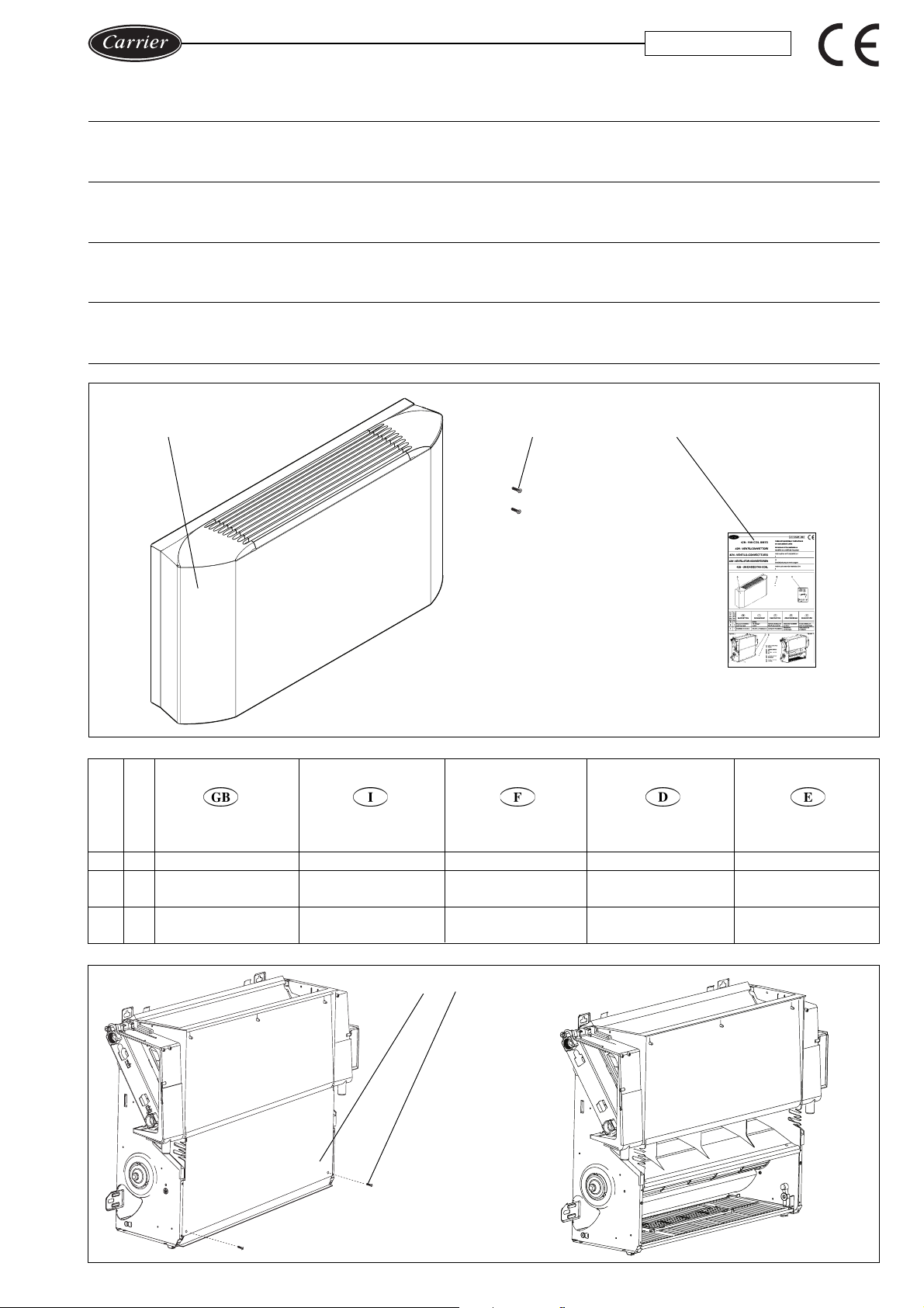
Ref. Q.ty
Rif. Q.tà
Ref. Q.té
Bez. Anz.
Ref. Can.
a 1 Cabinet
b 2
c 1 Installation instruction
Fig./Abb. 2
DESCRIPTION
Cabinet fixing
screws
DESCRIZIONE
Mobile
Viti fissaggio
mobile
Istruzioni di installazione
d e
DESCRIPTION
Cabinet
Vis de fixation
cabinet
Consignes d’installation
d Lower metal sheet
e Screws
d
Lamiera inferiore
e
Viti
d Tôle inférieure
e Vis
d
Unteres Blech
e
Schrauben
BESCHREIBUNG
Gehäuse
Befestigungsschrauben
für das Gehäuse
Installations-
anweisungen
DESCRIPCIÓN
Mueble
Tornillos de fijación
del mueble
Instrucciones de
installación
Fig./Abb. 3
d Placa inferior
e Tornillos
Page 2
b
b
22
Fig./Abb. 4
Fig./Abb. 6
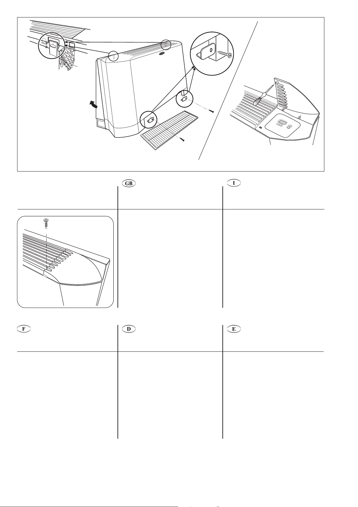
Assembly
Unscrew the 2 screws e (fig. 2) to
remove the lower metal sheet d.
Position cabinet a on the unit and hook
the cabinet holes on the back of the unit
(fig. 4).
Secure the cabinet by means of the 2
screws b supplied.
Furthermore it is possible to lock the
control cover.
Knock out the prepunched part of the
cover to insert the screw. (fig. 5).
Insert the screw and secure the cover
(fig. 6).
Fig./Abb. 5
Montaggio
Togliere la lamiera inferiore d svitando le
2 viti
e
Posizionare il mobile
ed agganciare i fori del mobile stesso sul
retro dell'unità (fig. 4).
Fissare il mobile con le 2 viti
corredo.
Bloccare il coperchio sul lato opposto a
quello del comando. A discrezione
dell'utilizzatore è possibile bloccare il
coperchio sul lato ove è montato il
comando. Sfondare la parte del
coperchio predisposta per il passaggio
della vite (fig. 5).
Inserire la vite e fissare il coperchio
(fig. 6).
(fig. 2).
a
sulla macchina
b
a
Montage
Enlever la tôle inférieure d en dévissant
les 2 vis e (fig. 2).
Positionner le cabinet a sur l’unité et
l’accrocher au moyen des trous situés
derrière l’unité (fig. 4).
Fixer le cabinet au moyen des 2 vis b
fournies.
Il est également possible de verrouiller le
couvercle de la commande.
Percer la partie pré-perforée du couvercle
pour insérer la vis (fig. 5).
Insérer la vis et fixer le couvercle (fig. 6).
The manufacturer reserves the right to change any product specifications without notice.
La cura costante per il miglioramento del prodotto può comportare senza preavviso, cambiamenti o modifiche a quanto descritto.
Le fabricant se réserve le droit de modifier les spécifications du produit, sans préavis.
Änderungen im Zuge der technischen Weiterentwicklung vorbehalten.
El fabricante se reserva el derecho de cambiar las especificaciones de los productos sin previo aviso.
Carrier S.p.A. - Via R. Sanzio, 9 - 20058 Villasanta (MI) Italy - Tel. 039/3636.1 Printed in Italy
Montage
Die beiden Schrauben e lockern und das
untere Blech
Das Gehäuse
positionieren und die Löcher auf der
Rückseite des Gerätes einhängen (Abb. 4).
Das Gehäuse mit den beiden mitgeliefertan
Schrauben
Auch die Regelungs-Abdeckung kann
arretiert werden.
Den vorgestanzten Teil der Abdeckung
ausbrechen, um die Schraube
einzuführen (Abb. 5).
Die Schraube einsetzen und den Deckel
festschrauben (Abb. 6).
d
abnehmen (Abb. 2).
a
auf dem Gerät
b
befestigen.
2
Montaje
Quitar la placa inferior d destornillando
los 2 tornillos e (fig. 2).
Colocar el mueble a sobre la máquina y
unir los orificios del mueble mismo sobre
la parte trasera de la unidad (fig. 4).
Fijar el mueble con 2 tornillos b en
dotación.
Además es posible bloquear la tapa de
los controles.
Atravesar en la parte superior de la tapa
por el semipunzonado previsto para el
paso de tornillo fijación (fig. 5).
Introducir el tornillo y fijar la tapa (fig. 6).
 Loading...