

Page 1

L010125H56 - 0502
42N F AN COIL UNITS
42N - VENTILCONVETTORI
42N - VENTILO-CONVECTEURS
42N - VENTILA TOR-KONVEKTOREN
42N - UNIDADES F AN COIL
Control kit
installation instructions
Istruzioni di installazione
kit comandi
Instructions d’installation
kit des commandes
Regelungseinheit
Installationsanweisungen
Instrucciones de instalación
kit de controles
a b c
Ref. Q.ty
Rif. Q.tà
Ref. Q.té
Bez. Anz.
Ref. Can.
a 1 Control
b 1
c 1 Wiring diagram
d 2
e - Sealing material
f 1
DESCRIPTION
Metal plate to fix
the control
Screws +
Screw anchors
Installation
instruction
f e d
DESCRIZIONE
Comando
Staffa fissaggio
comando
Schema elettrico
Viti + tasselli
ad espansione
Mastice
Istruzioni di
installazione
DESCRIPTION
Commande
Plaque métallique pour
fixer la commande
Schéma de câblage
Vis +
Cheville d’ancrage
Mastic
Consignes
d’installation
BESCHREIBUNG
Regelung
Metallplatte zur
Befestigung der Regelung
Schaltpläne
Schrauben + Tornillos
Spreizdübel Tacos
Dichtmasse
Installationsanweisungen
DESCRIPCIÓN
Control
Placa metálica para
fijar el control
Esquema eléctrico
Masilla
Instrucciones de
installación
+
Page 2
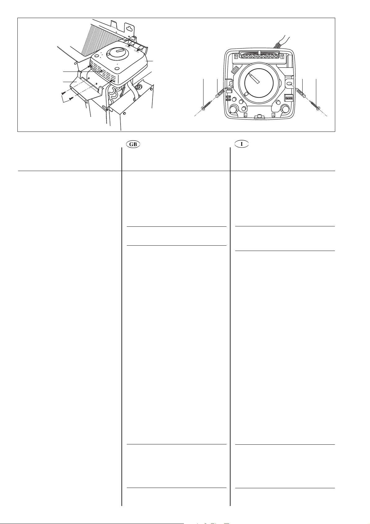
Fig./Abb. 2
g
b
a
h
Fig./Abb. 3
k l l k
j
i
Assembly
Unit-mounted control
Preliminary operations:
• Disconnect the main power supply.
• Remove cabinet.
• Access upper part of control box panel
positioning the control as shown (fig. 2).
IMPORTANT:
Make dip switch configuration before
closing the control cover.
• Open the control box panel, carry out
connections from the control to the terminal
block.
The cable from the control has two
polarized connectors to avoid risk of
connection errors.
• Place the temperature sensor in the proper
location.
• Place the control in the proper metal plate
tabs and fix it with the 2 screws j.
Montaggio
Comando a bordo macchina
Operazioni preliminari:
• Togliere l’alimentazione elettrica.
• Rimuovere il mobile.
• Accedere alla parte superiore del quadro
elettrico posizionando il comando come da
figura 2.
IMPORT ANTE:
Eseguire la configurazione dei
microinterruttori prima di chiudere il
comando con il relativo coperchio.
• Aprire il quadro elettrico ed eseguire i
collegamenti del cavo comando alla
morsettiera. Il cavo comando è provvisto di
due connettori di tipo polarizzato per
evitare errori di collegamento.
• Inserire la sonda temperatura
nell’apposita sede.
• Inserire il comando nelle apposite linguette
e fissare la staffa con le 2 viti j.
Wall-mounted control
• Prepare electrical connections between the
control terminal block and the unit control
box panel.
• Remove the control cover, unscrewing the
screw located in the bottom part.
• Disconnect the connection cable (provided)
and corresponding sensor (air) as they are
no longer needed.
• Configure jumper (JP1) to the “activated
internal sensor” position (see paragraph
“Use of temperature sensor”).
• Secure the control to the wall, marking the
drill holes (if necessary).
• Drill the holes previously marked.
Avoid drilling with the control already
placed on wall.
• Fix the control using the screw anchors L.
IMPORTANT:
• All connections between the unit and
the control must be placed into a
proper plastic conduit.
• Handle the control with extreme care.
Do not touch electronic components
to avoid damaging them.
• Replace the control cover and the screw
previously removed.
Comando a parete
• Predisporre i collegamenti elettrici tra la
morsettiera del comando e il quadro
elettrico del ventilconvettore.
• Togliere il coperchio del comando rimuovendo la vite di chiusura posizionata nella
parte inferiore.
• Scollegare il cavo di collegamento in
dotazione e relativo sensore (aria) in
quanto non più necessari.
• Configurare il cavallotto JP1 in posizione
“sensore interno attivo” (vedere paragrafo
“Uso del sensore di temperatura”).
• Posizionare il comando a parete contrassegnando i punti di foratura (quando
necessario).
• Eseguire le forature sui punti contrassegnati
precedenza. Evitare di eseguire forature
comando posizionato a parete.
• Fissare il comando utilizzando gli appositi
tasselli L.
IMPORTANTE:
• Tutti i collegamenti tra l’unità e il
comando devono essere eseguiti
sotto traccia.
• Manipolare il comando con estrema
cautela evitando di toccare i componenti
elettronici per non danneggiarli.
• Rimontare il coperchio del comando e la
vite tolta in precedenza.
con
in
2
Page 3
a Control
b Metal plate to fix the control
g Screw to close the control
h Control cable
i Control box panel
j Screws
k Screw
l Screw anchor
a
Regelung
b
Metallplatte zur Befestigung der Regelung
g
Schraube zurm Schließen
h
Regelungs-Kabel
i
Schaltkasten
j
Schrauben
k
Schraube
l
Dübel
a
b
g
h
i
j
k
l
der Regelung
Comando
Staffa fissaggio comando
Vite chiusura comando
Cavo comando
Quadro elettrico
Viti
Vite
Tassello
a Control
b Placa metálica para fijar el control
g Atornillar para cerrar el control
h Cable de control
i Cuadro eléctrico
j Tornillos
k Tornillo
l Taco
a Commande
b Plaque métallique pour fixer la commande
g Vis pour fermer la commande
h Câble de la commande
i Panneau de commande
j Vis
k Vis
l Cheville d’ancrage
Montage
Commande montée sur l’unité
Opérations préliminaires :
• Couper l’alimentation secteur.
• Retirer la carrosserie.
• Accéder à la partie supérieure du panneau
de commande en positionnant la
commande comme indiqué sur la figure 2.
IMPORTANT:
Configurer le commutateur dip avant de
fermer le couvercle de la commande.
• Ouvrir le panneau de commande, puis effectuer
les branchements entre la commande et la
plaque à bornes. Le câble de la commande
possède deux connecteurs polarisés pour
éviter d’éventuelles erreurs de branchement.
• Placer la sonde de température dans la
position qui convient.
• Placer la commande dans les languettes
appropriées de la plaque métallique et la
fixer à l’aide des 2 vis j.
Commande murale
• Effectuer les branchements électriques
entre la plaque à bornes de la commande
et le panneau de commande de l’unité.
• Ôter le couvercle de la commande en
dévissant la vis placée dans la partie inférieure.
• Débrancher le câble de branchement
(fourni) et la sonde correspondante (air) car
ils ne sont plus nécessaires.
• Configurer le pont (JP1) en fonction de la
position de la “sonde interne activée” (voir
paragraphe “Utilisation de la sonde de
température”).
• Fixer la commande au mur en marquant les
trous à percer (si nécessaire).
• Percer les trous précédemment marqués.
Eviter de percer avec la commande déjà au
mur.
• Fixer la commande à l’aide des chevilles
d’ancrage L.
IMPORTANT :
• Tous les branchements réalisés entre
l’unité et la commande doivent être
placés dans un tube plastique
approprié.
• Manipuler la commande avec un soin
extrême. Ne pas toucher les
composants électroniques pour éviter
de les endommager.
• Replacer le couvercle de la commande et la
vis précédemment ôtée.
Montage
Gerätemontierte Regelung
Erste Vorbereitungen:
• Die Stromversorgung abtrennen.
• Das Gehäuse entfernen.
• Den Schaltkasten oben öffnen und die
Regelung wie gezeigt positionieren (Abb. 2).
WICHTIG:
Vor dem Schließen der
Regelungsabdeckung die KippschalterKonfiguration vornehmen.
•
Den Schaltkasten öffnen, die Anschlüsse
von der Regelung zum Klemmblock
vornehmen. Das Kabel von der Regelung
hat zwei polarisierte Anschlüsse, um
Anschlussfehler zu vermeiden.
• Den Temperatursensor in die richtige
Position bringen.
• Die Regelung in die korrekten Ansätze an
der Metallplatte einsetzen und mit den
beiden Schrauben j befestigen.
Wandmontierte Regelung
• Die elektrischen Anschlüsse zwischen
dem Regelungs-Klemmblock und dem
Geräte-Schaltkasten vorbereiten.
• Die Regelungsabdeckung durch Lösen
der Schraube unten entfernen.
• Das Anschlusskabel (mitgeliefert) und den
zugehörigen Sensor (Luft) abtrennen, da
sie nicht mehr benötigt werden.
• Überbrückung JP1 als “aktivierten internen
Sensor” konfigurieren (siehe Abschnitt
“Verwendung des Temperatursenors”).
• Die Regelung an der Wand sichern und
die Bohrlöcher markieren (falls
erforderlich).
• Die vorher markierten Löcher bohren.
Nicht bohren, wenn sich die Regelung
bereits an der Wand befindet.
• Die Regelung mit den Dübeln
befestigen.
WICHTIG:
• Alle Anschlüsse zwischen dem Gerät und
der Regelung müssen durch eine
geeignete Kunststoff-Kabeldurchführung
laufen.
• Die Regelung äußerst vorsichtig
handhaben. Die elektronische Teile nicht
berühren, da sie beschädigt werden
könnten.
• Die Regelungsabdeckung und die vorher
entfernte Schraube wieder anbringen.
L
Montaje
Control montado sobre la unidad
Operaciones preliminares:
• Desconectar la alimentación eléctrica.
• Desmontar el mueble.
• Acceder a la parte superior del cuadro
eléctrico, colocando el control de la forma
indicada (fig. 2).
IMPORTANTE:
Realizar la configuración de los
conmutadores dip antes de cerrar la tapa
del control.
•
Abrir el cuadro eléctrico, realizar las
conexiones desde el control hasta las
bornas.
El cable del control tiene dos conectores
codificados para evitar el riesgo de errores
en el conexionado.
• Situar el sensor de temperatura en la
posición correcta.
• Situar el control en las lengüetas de chapa
adecuadas y fijarlo con los 2 tornillos j.
Control montado en pared
• Preparar las conexiones eléctricas entre
las bornas del control y el cuadro
eléctrico.
• Desmontar la tapa del control,
desatornillando el tornillo situado en su
parte inferior.
• Desconectar el cable de conexión
(suministrado) y el sensor correspondiente
(aire), ya que no son necesarios.
• Configurar el puente (JP1) a la posición
“sensor interno activado” (ver apartado
“Uso del sensor de temperatura”).
• Fijar el control a la pared, marcando los
taladros (si es necesario).
• Hacer los taladros marcados previamente.
Evitar taladrar con el control ya colocado
sobre la pared.
• Fijar el control usando los tacos L.
IMPORTANTE:
• Todas las conexiones entre la unidad y
el control deben llevarse en un
conducto plástico adecuado.
• Manipular el control con mucho
cuidado. No tocar los componentes
electrónicos para evitar dañarlos.
• Volver a colocar la tapa del control y el
tornillo extraído previamente.
3
Page 4
Control type “U” /
Comando tipo “U”
Commande type “U”
Control tipo “U”
Regelungstyp
/
“U”
Control type “A and B” /
B”
/ Commande type “A et B” /
“A und B” / Control tipo “A y B”
20°c
Comando tipo “A e
Regelungstyp
H
A
OFF
A
B
C
D
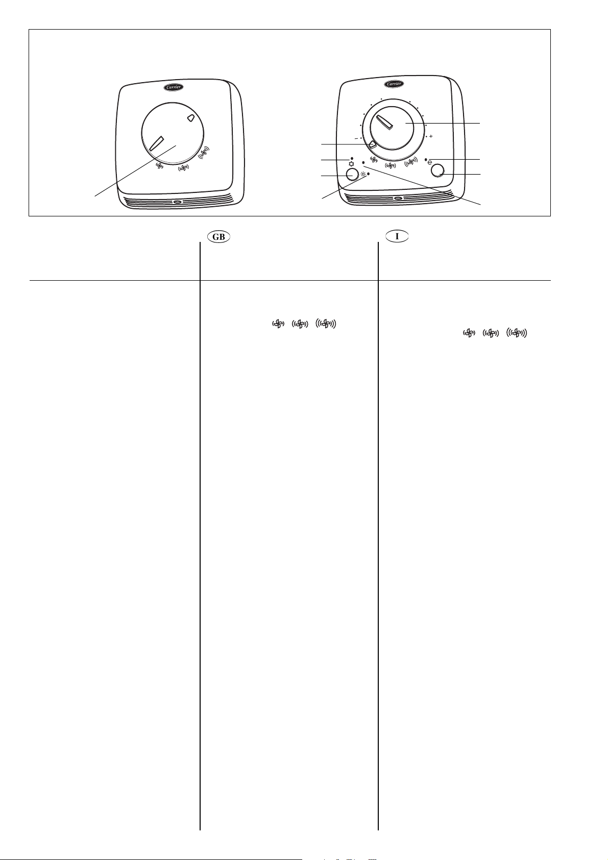
Controls
Type “U” control
This is an electromechanical control with a 4
position knob for unit OFF and fan speed
regulation (OFF This control cannot be used for room
temperature adjustment.
Type “A” and “B” control
Type “A” control is used in 2-pipe systems.
Type “B” control is used in 4-pipe systems
and 2-pipe systems with electric heater.
Functions
(type “A” and “B” controls)
Type “A” and “B” controls have a knob to
select the temperature, with a range from
10°C to 30°C, and room temperature is
maintained at the selected value.
Fan operation
With the fan speed selector A, fan mode can
be set either manually or automatically.
In the manual mode it is possible to select
three fan speeds (low/ medium/high)
according to personal preference.
In the auto mode fan speed is regulated by a
microprocessor in the control in relation to
the temperature chosen.
During installation, it is possible to select
continuous fan operation via the switch
located on the electronic board (see
paragraph “Dip-switch configuration”).
Fan operation during heating mode is
delayed by one minute to allow for
dispersion of residual heat present on the
heat exchanger coil or on the electric
heater if installed (only for type “B”
control).
As an option (only for type “A” control), fan
operation can be disabled during heating by
means of a sensor if water temperature is
below 40°C, and during cooling if water
temperature is above 18°C.
These two functions allow improved comfort
levels during winter by avoiding undesired
fan operation and during summer by turning
the fan coils ON and OFF automatically in
relation to the water temperature.
Frost-protection
This function keeps the temperature from
dropping below 7°C in rooms not used for
long periods of time.
When this temperature is reached, the
control activates the valve(s) and puts the
fan on high speed.
The frost protection function can be activated
through the associated micro-switch; if
enabled, this function activates even when
the control is in the OFF position.
- -
4
OFF
A
AUTO
G
F
E
Comandi
Comando tipo “U”
Questo comando è di tipo elettromeccanico,
dotato di commutatore rotativo a 4 posizioni
).
per spegnimento e regolazione della
di ventilazione (OFF - - - ).
Non sono previste funzioni di regolazione
della temperatura interna.
Comando tipo “A” e “B”
Il comando di tipo “A” viene utilizzato negli
impianti a 2 tubi. Il comando di tipo “B” viene
utilizzato negli impianti a 4 tubi e 2 tubi con
riscaldatore elettrico.
Funzioni (comandi “A” e “B”)
I comandi di tipo “A” e “B” provvedono a
mantenere la temperatura interna
impostata dalla manopola tra 10°C e 30°C.
Ventilazione
Tramite il selettore della velocità del ventilatore
A
è possibile scegliere in modo manuale o
automatico la modalità di funzionamento del
ventilatore. In modalità manuale è possibile
scegliere tre tipi di velocità (bassa/media/alta)
in funzione delle necessità. In modalità auto la
velocità del ventilatore è regolata dal microprocessore
del comando in funzione della temperatura
scelta. Durante l’installazione è tuttavia possibile
selezionare
sui microinterruttori presenti sulla scheda
elettronica (vedere configurazione dip-switch).
La ventilazione in modalità riscaldamento
viene ritardata di circa un minuto per
permettere lo smaltimento del calore
residuo presente sulla batteria di scambio
termico o sui riscaldatore elettrico se
installati (solo comando tipo “B”).
Mediante apposito sensore (optional) è
possibile escludere la ventilazione quando in
modalità riscaldamento la temperatura
dell'acqua è inferiore a 40 °C e in modalità
raffrescamento è superiore a 18°C (solo per
comando tipo A).
Queste due funzioni permettono di ottenere
un maggior comfort durante il funzionamento
invernale evitando ventilazioni indesiderate,
mentre in modalità estiva consentono lo
spegnimento e l’accensione in modo
automatico di tutti i ventilconvettori in
funzione della temperatura dell’acqua.
Antigelo
La funzione antigelo permette di evitare in
ambienti non frequentati per lunghi periodi
che la temperatura scenda sotto 7°C.
Raggiunta questa temperatura il controllo
provvede ad attivare la/e valvola/e e il
ventilatore alla alta velocità. La funzione
antigelo può essere attivata configurando il
relativo microinterruttore; se abilitata è attiva
anche con comando in posizione OFF.
la ventilazione continua, agendo
velocità
Page 5

A ON/OFF/fan speed selector
B Green LED - cooling operation
C Seasonal changeover button
D Red LED - heating operation
E Yellow LED - automatic operation
(only for type “B”)
F Energy saving button
G Yellow LED - energy saving operation
H Temperature knob
A
EIN/AUS/Ventilatordrehzahl-Wählschalter
B
Grüne LED – Kühlbetrieb
C
Taste für jahreszeitabhängige Umschaltung
D
Rote LED – Heizbetrieb
E
Gelbe LED – Automsatikbetrieb
(nur für Typ “B”)
F
Energiespar-Knopf
G
Gelbe LED – Energiespar-Betrieb
H
Temperaturschalter
A
Selettore acceso/spento/velocità ventilatore
B
LED verde funzione raffrescamento
C
Pulsante cambio stagionale
D
LED rosso funzione riscaldamento
E
LED giallo funzione auto (solo per tipo “B”)
F
Pulsante “energy saving” (risparmio energetico)
G
LED giallo funzione “energy saving” (risparmio
energetico)
H
Manopola temperatura
A Sélecteur MARCHE-ARRÊT/de vitesse du
ventilateur
B LED verte – mode refroidissemen
C Bouton de commutation été/hiver
D LED rouge - mode chauffage
E LED jaune - mode automatique
(uniquement pour type “B”)
F Touche ÉCO
G LED jaune - mode économie d’énergie
H Bouton de réglage de la température
A ON/OFF / Selector de la velocidad del ventilador
B LED verde - refrigeración
C Botón de conmutación estacional
D LED rojo - calefacción
E LED amarillo - funcionamiento automático
(sólo para el tipo “B”)
F Botón de ahorro energético
G LED amarillo - funcionamiento con ahorro energético
H Selector de temperatura
Commandes
Commande type “U”
Il s’agit d’une commande électromagnétique
comportant un bouton à 4 positions pour arrêter
l’unité (OFF) et régler la vitesse du ventilateur
(OFF ne sert pas à réguler la température des pièces.
Commandes type “A” et “B”
La commande type “A” est utilisée dans les
systèmes à 2 tuyaux. La commande type “B”
est utilisée dans les systèmes à 4 tuyaux et à
2 tuyaux avec résistance électrique.
Fonctions (commandes type “A” et “B”)
Les commandes “A” et “B” comportent un
sélecteur de température (plage comprise entre
10°C et 30°C) qui maintient la température
de la pièce à la valeur sélectionnée.
Fonctionnement du ventilateur
Avec le sélecteur de vitesse du ventilateur A,
le mode de fonctionnement du ventilateur
peut être réglé soit manuellement, soit
automatiquement. En mode manuel,
l’utilisateur a le choix entre trois vitesses
(faible/moyenne/rapide) selon ses
personnelles. En mode automatique
ventilateur est réglée par un microprocesseur logé
dans le boîtier de commande en fonction de la
température choisie. Pendant l’installation, il est
possible d’opter pour un fonctionnement continu
du ventilateur grâce au commutateur figurant
sur la carte électronique (voir paragraphe
“Configuration du commutateur dip”).
En mode chauffage, le ventilateur ne se met en
marche qu’au bout d’une minute afin de permettre
la dispersion de la chaleur résiduelle présente sur
la batterie
la résistance
(uniquement pour la commande de type “B”).
En option (uniquement pour commande du
type A), le ventilateur peut être désactivé au
moyen de la sonde correspondante, en mode
chauffage lorsque la température de l’eau est
inférieure à 40°C, et en mode refroidissement
lorsqu’elle est supérieure à 18°C. Ces deux
fonctions permettent d’obtenir de meilleurs
niveaux de confort en évitant que le
ventilateur ne se déclenche de manière
intempestive en hiver et en arrêtant/mettant
en marche automatiquement les ventiloconvecteurs en fonction de la température
de l’eau en été.
Protection antigel
Cette fonction permet de maintenir une
température de 7°C dans les pièces
inoccupées pendant de longues périodes.
Lorsque cette température est atteinte, la
commande active la(les) vanne(s) et met le
ventilateur sur vitesse rapide. La fonction
antigel peut être activée en configurant le
commutateur correspondant; lorsqu’elle est
activée, elle est active également lorsque la
commande est sur ARRET (OFF).
- -
de
l’échangeur de chaleur ou sur
électrique s’il y en a une
).Cette commande
préférences
, la vitesse du
Regelungen
Regelungstyp “U”
Dies ist eine elektromechanische Regelung
einem 4-Positions-Schalter zum Ausschalten
Geräts und zur Ventilatordrehzahl-Regelung (AUS
zur Raumtemperaturregelung verwendet werden.
Regelungstypen “A” und “B”
Regelungstyp “A” ist für Zweileiter-Systeme
Regelungstyp “B” ist für Vierleiter-Systeme
und Zweileiter-Systeme mit Elektroheizung.
Funktionen (Regelungstypen“A” und “B”)
Die Regelungstypen “A” und “B” haben
einen Knopf zur Temperaturwahl innerhalb
eines Bereichs von 10°C bis 30°C, und die
Raumtemperatur wird auf dem gewählten
Wert gehalten.
Ventilatorbetrieb
Mit dem Ventilatordrehzahl-Wählschalter
kann der Ventilatorbetrieb entweder auf
manuell oder automatisch eingestellt werden.
In der manuellen Betriebsart können wie
gewünscht drei Ventilatordrehzahlen gewählt
werden (niedrig/mittel/hoch). In der
automatischen Betriebsart wird die
Ventilatordrehzahl von einem Mikroprozessor in
der Regelung abhängig von der gewählten
T emperatur geregelt. Bei der Installation kann
kontinuierlicher Ventilatorbetrieb über einen
Schalter an der Elektronikplatine gewählt werden
(
siehe Abschnitt “Kippschalter-Konfiguration”).
Ventilatorbetrieb im Heizmodus wird um
eine Minute verzögert, um eine Abführung
Restwärme am Wärmetauscher oder – falls
vorhanden - an der Elektroheizung (nur für
Regelungstyp “B”) zu gestatten.
Wahlweise (nur für Regelungtyp “A”) kann der
Ventilatorbetrieb im Heizmodus über einen
Sensor in der Wasserverrohrung gesperrt
werden, wenn die Wassertemperatur unter
40°C liegt, bzw. im Kühlmodus, wenn die
Wassertemperatur über 18°C liegt.
Diese beiden Funktionen gestatten ein
verbessertes Komfortniveau im Winter, indem
sie unerwünschten Ventilatorbetrieb vermeiden
und im Sommer, indem sie die VentilatorKonvektoren abhängig von der
Wassertemperatur automatisch ein- und
ausschalten.
Frostschutz
Diese Funktion sorgt dafür, dass die
Temperatur in Räumen, die länger unbenutzt
bleiben, nicht unter 7°C abfällt. Wird diese
Temperatur erreicht und ist die FrostschutzFunktion durch einen Kippschalter an der
Elektronik-Platine freigegeben, aktiviert die
Regelung das (die) Ventil(e) und stellt die
hohe Ventilatordrehzahl ein.
Die Frostschutz-Funktion wird, wenn sie
freigegeben ist, aktiviert, selbst wenn die
Regelung sich in der AUS-Stellung befindet.
- -
mit
des
). Diese Regelung kann nicht
A
der
5
Controles
Control tipo “U”
Este es un control electromecánico con un selector
para el apagado de la unidad y regulación
velocidad del ventilador (OFF Este control no puede ser utilizado para el
ajuste de la temperatura de la habitación.
Control de tipo “A” y “B”
El control de tipo “A” usado en sistemas de 2
tuberías. El control de tipo “B” usado en
sistemas de 4 tuberías y en sistemas de 2
tuberías con resistencia eléctrica.
Funciones
(controles de los tipo “A” y “B”)
Los controles del tipo “A” y “B” disponen de
un selector de temperatura con un rango
entre 10ºC y 30ºC, la temperatura de la
habitación se mantiene en el valor seleccionado.
Funcionamiento del ventilador
Con el selector de la velocidad del ventilador
A, el modo de funcionamiento del ventilador
puede definirse como manual o automático.
En el modo manual es posible seleccionar tres
velocidades del ventilador (baja/media/alta)
según las preferencias personales. En el modo
automático la velocidad del ventilador es
regulada por un microprocesador del control
en función de la temperatura seleccionada.
Durante la instalación, es posible seleccionar
un funcionamiento continuo del ventilador,
mediante el conmutador situado en la tarjeta
electrónica (ver el apartado “Configuración de
los conmutadores Dip”). En el modo de
calefacción, el funcionamiento del
ventilador se retarda un minuto para
permitir la evacuación del calor residual de
la batería del intercambiador de calor o de
la resistencia eléctrica, si está instalada
(sólo en el control tipo “B”).
Por medio del sensor correspondiente
(opcional), se puede desactivar la ventilación
cuando en la modalidad calefacción la
temperatura del agua es inferior a 40º C y en
la modalidad refrigeración es superior a 18º
C (solamente para el control tipo A) Estas
dos funciones permiten unos mayores niveles
de confort, durante el
funcionamiento no deseado
durante el verano al conectar y desconectar
automáticamente los fan coils en función de
la temperatura del agua.
Protección frente a heladas
Esta función impide que la temperatura sea
inferior a 7ºC en habitaciones que estén
desocupadas durante períodos largos de
tiempo.
Alcanzada esta temperatura, el
control activa la /las válvula/ válvulas y el
ventilador a la alta velocidad.
La función antihielo puede ser activada
configurando el microinterruptor
correspondiente; si la función habilitada está
activa incluso con el control en posición OFF.
invierno al evitar un
del ventilador y
- -
de la
).
Page 6

Controls
Comandi
Energy saving
This function is especially useful when air
conditioning at night or in rooms where the
user is likely to be absent for a longer period
of time.
In this case, pushing button raises the
temperature during cooling by 4°C and
lowers it during heating by 4°C.
Enabling this function (yellow LED ON) cuts
out other displays.
During energy saving, even the brightness of
the yellow LED is dimmed.
Seasonal changeover
Manual
Selection of heating/cooling is done manually
by pushing the button on the control.
Centralised (only for type “A” control)
Centralised seasonal changeover can be
done in two ways:
- by a switch located on the central control
panel that allows heating/cooling mode
changeover
- by a temperature sensor located in
contact with the entering water pipe.
In this last mode, fan coil operation is driven
by the control, in cooling or heating,
depending on the temperature read by the
sensor.
Switch and sensor operate on 230V power
supply, so both must be adequately
insulated.
If the seasonal manual changeover button is
pushed while the centralised changeover
mode is activated, the corresponding LED
will briefly flash while maintaining the
activated mode.
In any case, centralised changeover takes
priority over local changeover.
Automatic, based on air temperature
(only for type “B” control)
The automatic seasonal changeover allows
automatic switching of the fan coil operating
mode to cooling or heating, depending on the
temperature set by the user and on the room
temperature.
External contact
The control has an input that can be used as
window contact or presence detection.
When such a signal is activated (presence of
line voltage on the terminal block contact) the
control is set to OFF mode.
As a consequence, all outputs (fan, valves
etc.) are disconnected, and only the frost
protection is active, if switched ON by the
appropriate dip-switch.
Use
ON/OFF/fan speed selector
OFF In this position the control is OFF
and all functions are disabled.
If the frost protection function is
selected by the dip-switch, this is
activated even if the control is in OFF
position.
With selector in this position, the fan
operates at low speed.
With selector in this position, the fan
operates at medium speed.
With selector in this position, the fan
operates at high speed.
AUTO The control maintains the selected
temperature, acting automatically on
the fan speed.
“Energy saving” (risparmio energetico)
Questa funzione è particolarmente utile durante
il funzionamento notturno o negli ambienti
climatizzati nei quali si suppone di dover
rimanere assenti per un certo periodo di tempo.
In questo caso agendo sul pulsante è
possibile aumentare di
durante il funzionamento in modalità
raffrescamento e di ridurre di
temperatura durante il funzionamento
modalità riscaldamento. L’abilitazione di
questa funzione (LED giallo inserito) esclude
altre visualizzazioni. Durante il funzionamento
“Energy saving” viene attenuata anche la
luminosità del LED giallo.
4°C la temperatura
4°C la
in
in
le
Cambio stagionale
Manuale
La selezione riscaldamento/raffrescamento,
viene effettuata manualmente tramite il
pulsante sul comando.
Centralizzato (solo comando tipo “A”)
Il cambio stagionale centralizzato può essere
effettuato in due modi:
- tramite un deviatore posizionato nella
centrale di comando che permette di
commutare la modalità riscaldamento/
raffrescamento
- tramite una sonda di tipo a contatto da
posizionare sulla tubazione di ingresso
dell’acqua
In quest’ultima modalità, il funzionamento del
ventilconvettore viene pilotato dal comando in
riscaldamento o in raffrescamento a seconda
della temperatura rilevata dal sensore.
Sia il deviatore che la sonda, funzionano
tensione di 230V, per cui devono essere
adeguatamente isolati. La pressione sul tasto
cambio stagionale manuale mentre è attivo il
cambio stagionale centralizzato provoca un
breve lampeggio del LED relativo alla
modalità di
modo il cambio stagionale centralizzato
esclude il funzionamento del cambio
stagionale locale.
Automatico sull’aria
(solo comando tipo “B”)
Il cambio stagionale automatico consente di
commutare in modo automatico il funzionamento
del ventilconvettore in modalità riscaldamento
raffrescamento in funzione della temperatura
impostata dall’utente e la temperatua interna.
funzionamento attiva.
Ad ogni
con
o
Contatto esterno
Il comando è dotato di un ingresso da utilizzare
come contatto finestra, o sensore di presenza.
Quando tale segnale è abilitato (presenza
del potenziale di linea al contatto della
morsettiera) il comando viene posto in OFF.
Di conseguenza vengono disabilitate tutte le
uscite (ventilatore, valvole, etc.) e rimane
attiva la sola funzione di antigelo se abilitata
dal relativo “dip switch”.
Utilizzo
Selettore acceso/spento e velocità di
ventilazione
OFF
in questa posizione il comando è spento
e tutte le funzioni sono disabilitate.
Se la funzione antigelo (frost-protection)
viene selezionata tramite l’apposito
microinterruttore, questa diventa attiva
anche con comando in posizione OFF.
con il selettore in questa posizione, il
ventilatore gira alla bassa velocità.
con il selettore in questa posizione il
ventilatore gira alla media velocità.
con il selettore in questa posizione il
ventilatore gira alla alta velocità.
AUTO il comando mantiene la temperatura
i
mpostata commutando automaticamente
la velocità di ventilazione.
6
Page 7

Commandes
Regelungen
Controles
Économie d’énergie
Économie d’énergie est particulièrement utile
pour la climatisation des pièces la nuit ou pour
les pièces inoccupées pendant de longues
périodes. Dans ces cas de figure, il suffit d’appuyer
sur la touche pour élever la température, en
mode refroidissement, de 4°C et la réduire, en
mode chauffage, de 4°C.Tous les autres
affichages disparaissent lorsque cette fonction
est activée (LED jaune allumée). En mode éco,
même l’intensité de la LED jaune est réduite.
Commutation été/hiver
Manuelle
La sélection du mode chauffage/
refroidissement s’effectue manuellement en
poussant sur le bouton de la commande.
Centralisée (uniquement pour la
commande de type “A”)
La commutation été/hiver centralisée peut
s’effectuer de deux manières :
- par le biais d’un commutateur figurant sur
le panneau de commande central qui
permet de passer d’un mode de
fonctionnement à l’autre
- Par le biais d’une sonde de température
en contact avec le tuyau d’eau à l’entrée
du circuit.
Dans ce dernier cas, le ventilo-convecteur est
piloté, en mode refroidissement ou chauffage,
par la commande en fonction de la
température lue par la sonde.
Le commutateur et la sonde sont alimentés
en 230V et doivent donc être tous deux isolés
de manière convenable. Lorsqu’on appuie
sur le bouton de commutation été/hiver manuelle
alors que le mode de commutation centralisée
était activée, la LED correspondante clignote
brièvement tout en maintenant le mode activé. Dans
tous les cas, le mode de commutation centralisée
la priorité sur le mode de commutation local.
Automatique, basée sur la température de
l’air (uniquement pour la commande de
type “B”)
Le système de commutation automatique
hiver permet de passer automatiquement
mode refroidissement au mode chauffage
selon la température réglée par l’utilisateur et
la température de la pièce.
a
été/
du
Contact externe
La commande possède une entrée qui peut
être utilisée comme contact de fenêtre ou
détecteur d’occupation des pièces.Lorsqu’un
tel signal est activé (présence d’une tension
secteur sur le contact de la plaque à bornes),
la commande est réglée sur OFF. Par conséquent
toutes les sorties (ventilateur, vannes, etc.)
sont déconnectées et seule la fonction antigel
est active si elle a été activée au moyen du
commutateur dip.
,
Utilisation
Sélecteur de vitesse du ventilateur/
MARCHE-ARRÊT (ON/OFF)
ARRÊT
Lorsque le sélecteur est réglé sur cette
position, la commande est éteinte et
toutes les fonctions désactivées. Si la
fonction antigel a été sélectionnée à l’aide
du commutateur dip, celle-ci sera activée
même si la commande est sur OFF.
Lorsque le sélecteur est réglé sur cette
position, le ventilateur tourne à vitesse lente.
Lorsque le sélecteur est réglé sur
cette position, le ventilateur tourne à
vitesse moyenne.
Lorsque le sélecteur est réglé sur cette
position, le ventilateur tourne à vitesse rapide.
AUTO
La commande maintient la température
sélectionnée en agissant automatiquement
sur la vitesse du ventilateur.
Energiespar-Betrieb
Diese Funktion ist besonders nützlich, wenn
Räume nachts klimatisiert werden oder in
Räumen, wo der Benutzer wahrscheinlich
längere Zeit abwesend ist. In diesem Fall die
Taste drücken, wodurch die Temperatur im
Kühlbetrieb um 4°C erhöht, bzw. im
Heizbetrieb um 4°C gesenkt wird. Freigabe
dieser Funktion
anderen Anzeigen.
selbst die Helligkeit der gelben LED
abgeschwächt.
(gelbe LED AN) sperrt die
Im Energiespar-Betrieb ist
Jahreszeitabhängige Umschaltung
Manuell
Die Wahl von Kühlung/Heizung erfolgt manuell
durch Drücken der Taste an der Regelung.
Zentral (nur für Regelungstyp “A”)
Zentrale jahreszeitabhängige Umschaltung
kann auf zwei Arten erfolgen:
- durch eine Schalter an der zentralen
Regeltafel die Heiz-/KühlmodusUmschaltung gestattet
- durch einen Temperatursensor, der mit
der Wassereintrittsleitung in Kontakt steht.
In dieser Betriebsart wird der Gerätebetrieb
durch im Kühl- und Heizmodus abhängig von
der vom Sensor gemessenen Temperatur
geregelt.
Schalter und Sensor arbeiten mit einer
Stromversorgung von 230 V, daher müssen
beide ausreichend isoliert werden.
Wird der Knopf für jahreszeitabhängige
Umschaltung gedrückt, während die
zentralisierte Umschaltung aktiv ist, leuchtet
die zugehörige LED kurz auf, wobei die
aktivierte Betriebsart beibehalten wird.
Zentrale Umschaltung übersteuert immer die
lokale Umschaltung.
Automatisch, basierend auf der Lufttemperatur
(nur für Regelungstyp“B”)
Die automatische jahreszeitabhängige
Umschaltung gestattet automatisches
Umschalten der Geräte-Betriebsart auf
Kühlung oder Heizung, abhängig von der vom
Benutzer eingestellten Temperatur und der
Raumtemperatur.
Externer Kontakt
Die Regelung hat einen Eingang, der als
Fensterkontakt oder Anwesenheits-Detektor
benutzt werden kann. Wenn ein solches
Signal aktiviert ist (Vorhandensein von
Netzspannung am Klemmblock-Kontakt), wird
die Regelung in den AUS-Modus eingestellt.
Dadurch werden alle Ausgänge (Ventilatoren,
Ventile usw .) abgetrennt und es ist nur
Frostschutz
entsprechenden
wurde.
aktiv, wenn dieser durch den
Kippschalter EINgeschaltet
Verwendung
EIN/AUS (ON/OFF)/VentilatordrehzahlWählschalter
OFF In dieser Position ist die Regelung
AUSgeschaltet und alle Funktionen
sind gesperrt. Wurde die Frostschutz-
Funktion durch den Kippschalter gewählt,
bleibt diese aktiviert, selbst wenn die
Regelung in der OFF-Position ist.
Ist der Wählschalter in dieser
Position, läuft der Ventilator mit
niedriger Drehzahl.
u
Ist der Wählschalter in dieser Position,
läuft der Ventilator mit mittlerer Drehzahl.
Ist der Wählschalter in dieser
Position, läuft der Ventilator mit hoher
Drehzahl.
AUTO Die Regelung erhält die gewählte
Temperatur aufrecht und wählt die
Ventilatordrehzahl automatisch.
7
Ahorro energético
Esta función es especialmente útil cuando se
quiere acondicionar el aire durante la noche o
en habitaciones en las que el usuario vaya a
estar ausente períodos prolongados de
tiempo. En este caso al pulsar el botón se
aumenta la temperatura 4ºC durante la
refrigeración y se disminuye 4ºC durante la
calefacción. Al activar esta función (LED
amarillo encendido) se apagan los otros
indicadores. Con ahorro energético se
reduce incluso el brillo del LED amarillo.
Conmutación estacional
Manual
La selección de refrigeración/calefacción se
realiza manualmente pulsando el botón del
control.
Centralizado (sólo para el control tipo “A”)
La conmutación estacional centralizada
puede realizarse de dos maneras:
- mediante un conmutador situado en el
control central que permite la conmutación
de modo calefacción/refrigeración
- mediante un sensor de temperatura en
contacto con la tubería de entrada de agua.
De esta última forma, el funcionamiento del
fan coil se regula desde el control, tanto en
refrigeración como en calefacción, en función
de la temperatura de este sensor.
El conmutador y el sensor trabajan con una
alimentación de 230V, por lo que ambos
deben estar adecuadamente aislados.
Si se pulsa el botón de conmutación
estacional manual cuando está activado el
modo de conmutación centralizado, el LED
correspondiente parpadeará brevemente
manteniéndose el modo activo. En cualquier
caso, la conmutación centralizada tiene
prioridad sobre la conmutación local.
Automático, en función de la temperatura
del aire (sólo para el control tipo “B”)
La conmutación estacional automática
permite el cambio automático del modo de
funcionamiento del fan coil entre refrigeración
y calefacción, en función de la temperatura
seleccionada por el usuario y la temperatura
ambiente.
Contacto externo
El control dispone de una entrada que
puede usarse para un contacto de ventana
o un detector de presencia. Cuando se
activa esta señal (presencia de tensión de
línea en el borna del contacto), el control
se pone en modo OFF.
de ello, se desconectan
Como consecuencia
todas las salidas
(ventilador, válvulas etc.), permaneciendo
sólo activa la protección frente a heladas,
siempre que se haya activado con el
conmutador dip adecuado.
Uso
ON/OFF/ selector de velocidad del ventilador
OFF En esta posición el control está
apagado y todas las funciones están
desactivadas. Si se ha seleccionado
la función de protección frente a
heladas con el conmutador DIP, esta
función también está activa cuando el
control está en posición OFF.
Con el selector en esta posición, el
ventilador funciona a velocidad baja.
Con el selector en esta posición, el
ventilador funciona a velocidad media.
Con el selector en esta posición, el
ventilador funciona a velocidad alta.
AUTO El control mantiene la temperatura
seleccionada actuando
automáticamente sobre la velocidad
del ventilador.
Page 8

Controls
Comandi
Temperature selector
Its purpose is to maintain the temperature at
the desired level.The reference value at the
centre of the range is 20°C .
By turning the knob towards the symbol ( – )
the temperature is reduced from the original
setting (minimum value is 10°C).
By turning the knob towards the symbol ( + ),
the temperature is raised from the original
setting (maximum value is 30°C).
Seasonal changeover button
This button allows selecting the operating
mode, cooling, heating or automatic (the last
function is only possible with type “B” control).
If the sensor for centralised changeover is
connected, this button is disconnected (only
on type “A” control).
Energy saving button
This button activates the energy saving
function which modifies room temperature as
follows: in heating, the selected temperature
is reduced by 4°C; in cooling, the selected
temperature is raised by 4°C.
Light indicators
Green LED
ON Indicates that the control is
Flashing Indicates that the control is
Red LED
ON
Flashing Indicates the presence of a
Yellow LED (A ) (only 4-pipe versions)
ON Indicates that the control is in
Green LED + yellow LED
Both ON Indicates that the control is
Red LED + yellow LED
Both ON Indicates that the control is
Yellow LED ( )
ON Indicates that the control is
Flashing Indicates (if connected) that
Red / green LED
Flashing Indicates that the control is
in cooling mode ( ).
in frost protection mode ( ).
Indicates that the control
is in heating mode ( ).
fault (sensor failed or not
connected).
automatic mode (A).
in automatic mode (A) -
cooling ( ).
in automatic mode (A) -
heating ( ).
in energy saving mode .
the external contact is
open.
in “Autotest” mode.
Dip-switch functions
Dip-switch No. 1
When ON permits enabling the frost
protection ( ) function.
Dip-switch No. 2
When ON permits fan operation at the
selected speed even if the set point is
satisfied.
Dip-switch No. 3
When ON restricts the range of temperature
selection, according to the following limits:
Cooling: minimum selectable
Heating: maximum selectable
Dip-switch No. 4
When ON periodically activates the fan even
if the set point is satisfied (air sampling).
temperature: 25°C.
temperature: 20°C.
8
Selettore temperatura
Permette di regolare la temperatura desiderata. Il valore di riferimento a centro
20°C. Ruotando la manopola verso
( – ) si ha una riduzione del valore della
termperatura impostata (valore minimo
Ruotando la manopola verso il simbolo
ha un aumento del valore della
impostata (valore massimo 30°C).
Pulsante cambio stagionale
Il pulsante permette di selezionare il modo di
funzionamento raffrescamento/riscaldamento
automatico (quest’ultima funzione solo per
comando tipo “B”). Se il sensore per il cambio
stagionale centralizzato è collegato, il pulsante
disabilitato (solo per comando tipo “A”).
Pulsante “Energy saving”
(risparmio energetico)
Il pulsante abilita il controllo a funzionare in modo
economico, modificando la temperatura interna:
riscaldamento, diminuendo la temperatura
selezionata di 4°C; in raffrescamento,
aumentando la temperatura selezionata di 4°C.
scala è di
il simbolo
10°C).
( + ) si
temperatura
o
è
in
Indicazioni luminose
LED verde
Acceso Indica che il comando è in
Lampeggiante Indica che il comando è in
LED rosso
Acceso Indica che il comando è in
Lampeggiante Indica la presenza di una
LED giallo (A ) (solo versione 4 tubi)
Acceso Indica che il comando è in
LED verde + LED giallo
Entrambi
accesi Indicano che il comando è
LED rosso + LED giallo
Entrambi
accesi Indica che il comando è in
LED giallo ( )
Acceso Indica che il comando è in
Lampeggiante Indica (se collegato)
LED rosso / verde
Lampeggiante Indicano che il comando è
modalità raffrescamento ( ).
modalità antigelo ( ).
modalità riscaldamento ( ).
anomalia (sonda interrotta).
modalità automatica (A).
in modalità auto (A) -
raffrescamento ( ).
modalità auto (A) -
riscaldamento ( ).
modalità “energy saving”
(risparmio energetico).
l’apertura del contatto esterno.
in modalità “Autotest”.
Funzioni “Dip-switch”
(microinterruttore)
Dip-switch n° 1
In posizione ON permette l’attivazione della
funzione antigelo ( ).
Dip-switch n° 2
In posizione ON consente il funzionamento del
ventilatore alla velocità selezionata anche quando
è stata raggiunta le temperatura di set-point.
Dip-switch n° 3
In posizione ON limita il campo di regolazione
della manopola temperatura secondo i
seguenti limiti:
Raffrescamento: temperatura minima
Riscaldamento: temperatura massima
Dip-switch n° 4
In posizione ON consente di attivare il
ventilatore ad intervalli regolari di tempo
anche quando è stata raggiunta le
temperatura di set-point (Air sampling).
selezionabile: 25°C.
selezionabile: 20°C.
Page 9

Commandes
Regelungen
Controles
Sélecteur de température
Le sélecteur de température a pour but de
maintenir la température au niveau souhaité. La
valeur de référence moyenne est de 20°C. Lorsqu’on
tourne le bouton vers le symbole ( – ), la température
diminue par rapport à la
(valeur minimale 10°C). Lorsqu’on tourne le bouton
vers le symbole ( + ), la température augmente par rapport
à la valeur initialement réglée (valeur maximale 30°C).
Bouton de commutation été/hiver
Ce bouton permet de sélectionner le mode de
fonctionnement : refroidissement, chauffage ou
automatique (cette dernière fonction n’est possible
que sur la commande type “B”). Si la
système de commutation été/hiver
est branchée, ce bouton est désactivé
sur la commande type “A”).
Touche Économie d’énergie
Cette touche active la fonction d’économie d’énergie,
qui modifie la température de la pièce de la manière
suivante : En mode chauffage,
sélectionnée est diminuée de
refroidissement, la température
augmentée de 4°C.
valeur initialement réglée
sonde du
centralisée
(uniquement
la température
4°C. En mode
sélectionnée est
Voyants lumineux
LED verte
Allumée
Clignote Indique que la commande
LED rouge
Allumée Indique que la commande
Clignote Indique la présence d’un
LED jaune (A ) (versions 4 tuyaux)
Allumée uniquement) Indique que la
LED verte + LED jaune
Toutes deux
allumées Indique que la commande
LED rouge + LED jaune
Toutes deux
allumées Indique que la commande
LED jaune ( )
Allumée Indique que la commande
Clignote Indique (s’il est branché)
LED rouge / verte
Clignote
Indique que la commande est
en mode refroidissement ( ).
est en mode antigel ( ).
est en mode chauffage ( ).
défaut (sonde défaillante ou
non branchée).
commande est en mode
automatique (A).
est en mode automatique
(A) - refroidissement ( ).
est en mode automatique
(A) - chauffage ( ).
est en mode économie
d’énergie .
que le contact externe est
ouvert.
Indique que la commande est
en mode “Test automatique”.
Temperatur-Wählschalter
Dieser hält die Temperatur auf dem
gewünschten Stand. Der Bezugswert in der
Mitte des Bereichs ist 20°C.
Wird der Knopf zum Symbol ( – ) hin gedreht,
wird die Temperatur vom Ausgangswert aus
gesenkt (Mindestwert ist 10°C).
Wird der Knopf zum Symbol
wird die Temperatur vom Ausgangswert
erhöht (Maximalwert ist 30°C).
Knopf für jahreszeitabhängige Umschaltung
Dieser Knopf gestattet die Wahl der
Betriebsart, Kühlung, Heizung oder
automatisch (letztere ist nur mit Regelungstyp
“B”
Umschaltung angeschlossen, wird dieser
Knopf abgetrennt (nur für Regelungstyp “A”).
Energiespar-Knopf
Dieser Knopf aktiviert die EnergiesparFunktion, welche die Temperatur wie folgt
ändert: Im Heizmodus wird die Temperatur
um 4°C gesenkt.
Im Kühlmodus wird die Temperatur um 4°C
erhöht.
Leuchtanzeigen
Grüne LED
AN
Blinkt Zeigt an, dass die Regelung
Rote LED
AN
Blinkt
Gelbe LED (A ) (nur Vierleiter-Versionen)
AN Zeigt an, dass die Regelung
Grüne LED und gelbe LED
Beide AN Zeigt an, dass die Regelung
Rote LED und gelbe LED
Beide AN Zeigt an, dass die Regelung
Gelbe LED ( )
AN Zeigt an, dass die
Blinkt Zeigt an (falls
Rote/grüne LED
Blinkt Zeigt an, dass die Regelung
Fonctions du commutateur dip
Commutateur dip n° 1
Lorsqu’il est sur ON, le commutateur dip n° 1
permet d’activer la fonction antigel ( ).
Commutateur dip n° 2
Lorsqu’il est sur ON, le commutateur dip n° 2
permet de faire fonctionner le ventilateur à la
température sélectionnée même si le point de
consigne est atteint.
Commutateur dip n° 3
Lorsqu’il est sur ON, le commutateur dip n° 3
restreint la plage de températures
sélectionnables en fonction des limites
suivantes :
Refroidissement:
Chauffage : température maximale
Commutateur dip n° 4
Lorsqu’il est sur ON, le commutateur dip n° 4 active
périodiquement le ventilateur même si le point
de consigne est atteint (échantillonnage de l’air).
température minimale
sélectionnable : 25°C.
sélectionnable : 20°C.
Kippschalter-Funktionen
Kippschalter 1
Ist dieser ON (EIN), kann die FrostschutzFunktion ( ) freigegeben werden.
Kippschalter 2
Ist dieser auf ON (EIN), wird Ventilatorbetrieb
bei der gewählten Drehzahl gestattet, selbst
wenn der Sollwert befriedigt ist.
Kippschalter 3
Ist dieser auf ON (EIN), wird die
Temperaturwahl wie folgt eingeschränkt:
Kühlung: wählbare
Heizung: wählbare
Kippschalter 4
Ist dieser auf ON (EIN), wird Ventilatorbetrieb
periodisch aktiviert, selbst wenn der Sollwert
befriedigt ist (Luft-Probenahme).
( + )
hin
gedreht,
aus
möglich). Ist der Sensor für zentrale
Zeigt an, dass die Regelung
im Kühlmodus ist ( ).
im Frostschutz-Modus ist
( ).
Zeigt an, dass die Regelung
im Heizmodus ist
Zeigt das Vorhandensein eines
( ).
Fehlers an (Sensor defekt
oder nicht angeschlossen).
im Automatik-Modus ist (A).
im Automatik-Modus ist
(A) – Kühlung ( ).
im Automatik-Modus ist
(A) – Heizung ( ).
Regelung
im Energiespar-
Modus ist
.
angeschlossen), dass der
externe Kontakt offen ist.
im Modus “Automatischer
Test” ist.
Mindesttemperatur: 25°C.
Maximaltemperatur: 20°C.
9
Selector de temperatura
Sirve para mantener la temperatura en el
valor deseado. El valor de referencia en el
centro del rango es 20ºC. Al girar el selector
hacia el símbolo
temperatura con respecto al valor inicial (el
valor mínimo es 10ºC). Al girar el selector
hacia el símbolo
temperatura con respecto al valor inicial (el
valor máximo es 30ºC).
Botón de conmutación estacional
Este botón permite seleccionar el modo de
funcionamiento, refrigeración, calefacción o
automático (esta última función sólo está
disponible con el control tipo
conecta un sensor para la conmutación
centralizada, este botón queda desconectado
(sólo en el control tipo “A”).
Botón de ahorro energético
Este botón activa la función de ahorro
energético que modifica la temperatura de la
habitación de la forma siguiente: Durante
calefacción, se disminuye la temperatura
seleccionada 4ºC. Durante la refrigeración,
aumenta la temperatura seleccionada 4ºC.
( – )
se reduce el valor de
( + )
se aumenta el valor de
“B”
). Si se
la
se
Indicadores luminosos
LED verde
Encendido Indica que el control está en
Parpadeante Indica que el control está
LED rojo
Encendido Indica que el control está en
Parpadeante Indica un fallo (fallo del
LED amarillo (A )
Encendido Indica que el control está
LED verde + LED amarillo
Ambos
encendidos Indica que el control está en
LED rojo + LED amarillo
Ambos
encendidos Indica que el control está en
LED amarillo ( )
Encendido Indica que el control está
Parpadeante Indica que el contacto
LED rojo / verde
Parpadeantes
modo de refrigeración ( ).
en modo de protección
frente a heladas( ).
modo de calefacción
sensor o no conectado).
(solo en las versiones de
4 tuberías)
en modo automático (A).
modo automático (A) -
refrigeración ( ).
modo automático (A) -
calefacción ( ).
en modo de ahorro
energético .
externo está abierto (si se
ha conectado).
Indica que el control está en
modo “autodiagnóstico”.
( ).
Funciones del conmutador Dip
Conmutador Dip Nr. 1
En la posición ON activa la protección frente
a heladas ( ).
Conmutador Dip Nr. 2
En la posición ON permite el funcionamiento
del ventilador a la velocidad seleccionada
incluso si se cumple el valor de consigna.
Conmutador Dip Nr. 3
En la posición ON, restringe el rango de
selección de temperaturas a los siguientes
límites:
Calefacción: temperatura mínima
Refrigeración: temperatura máxima
Conmutador Dip Nr. 4
En la posición ON se activa periódicamente el
ventilador incluso si se cumple el valor de
consigna (muestreo de aire).
seleccionable: 25°C.
seleccionable: 20°C.
Page 10

Controls
Comandi
A
2
3
4
JP1
A Coil sensor (optional)
2 Air sensor
3 Jumper to select remote sensor or
internal sensor
4 Internal temperature sensor
5 Dip-switch selector
A
Sensore batteria (opzionale)
2
Sensore aria
3
Cavallotto per selezione sensore
remoto o sensore interno
4
Sensore interno di temperatura
5
Selettore “Dip-switch”
A Sonde de ventilo-convecteur (en option)
2 Sonde de température d’air
3 Pont pour sélectionner la sonde à
distance ou la sonde interne
4 Sonde de température interne
5 Sélecteur de commutateur dip
A
Wärmetauscher-Sensor (wahlweise)
2
Luftsensor
3
Überbrückung zur Wahl des entfernten
oder internen Sensors
4
Interner Temperatursensor
5
Kippschalter-Wahl
A Sensor de batería (opcional)
2 Sensor de aire
3 Puente para seleccionar el sensor
remoto o el sensor interno
4 Sensor interno de temperatura
5 Conmutador Dip
Internal sensor (fig. A) /
(fig. A)
/ Sonde interne (fig. A) /
Sensor (Abb. A)
ON
OFF
1 2 3 4
Sensore interno
/ Sensor interno (fig. A)
Interner
JP1
Remote sensor (fig. B) /
/ Sonde à distance (fig. B) /
Sensore remoto (fig. B)
(Abb. B)
/ Sensor remoto (fig. B)
Entfernter Sensor
JP1
Dip-Switch configurations
Dip-switch 1
OFF Frost protection ( ) disabled.
ON Frost protection ( ) enabled.
Dip-switch 2
OFF Ventilation controlled by
thermostat.
ON Continuous ventilation.
Dip-switch 3
OFF Temperature block disabled.
5
ON Temperature block enabled.
Dip-switch 4
OFF Air sampling disabled.
ON Air sampling enabled.
NOTE:
Factory setting is with all dip-switches in
the OFF position.
Use of temperature sensor
Internal sensor:
This is used in all installations where the
control is wall-mounted. To activate it, close
jumper JP1 as shown in figure A.
Remote sensor:
This is used on all installations with unitmounted control. It is positioned on the return
air, close to the fan. To activate it, close
jumper JP1 as shown in figure B.
NOTE:
Factory setting is with activated remote
sensor.
Diagnostic warnings
The following alarm situations are indicated:
Defective sensors: the red LED flashes.
Possible causes:
• failure or short circuit of internal or remote
sensor;
• failure or short circuit of water temperature
sensor (optional and only on type “A” control).
Incorrect configuration
The yellow LED flashes every 0.25
seconds.
This happens when:
• in type “A” control, both centralised
seasonal changeover signals “RC and RH”
are enabled.
Autotest
The autotest function is activated by holding
the seasonal changeover button pressed
and at the same time pressing the “ ”
button three times within 1 second.
In this way it is possible to check the
starting of all fan coils.
The green and red LEDs will begin to flash.
Each of the various units will be activated
for 10 seconds in the following sequence:
Low fan speed.
Medium fan speed.
High fan speed.
CV Motorized cold-water valve.
HV Motorized hot-water valve, or
electric heater (only type “B” control
versions).
Elapsed 1 minute the control ends
the test mode.
Configurazioni “Dip-Switch”
(microinterruttore)
Dip 1
OFF Antigelo ( ) disabilitato.
ON Antigelo ( ) abilitato.
Dip 2
OFF Ventilazione controllata dal
termostato.
ON Ventilazione continua.
Dip 3
OFF Blocco temperature disattivato.
ON Blocco temperature attivato.
Dip 4
OFF “Air Sampling” disattivato.
ON “Air Sampling” attivato.
NOTA:
La configurazione di fabbrica è con tutti i
“Dip-switch” in posizione OFF.
Uso del sensore di temperatura
Sensore interno:
Viene usato in tutte le installazioni dove
viene effettuato il montaggio del comando a
parete.Per renderlo attivo, chiudere il
cavallotto JP1 come in figura A.
Sensore remoto:
Viene usato in tutte le installazioni dove
viene effettuato il montaggio del comando a
bordo macchina.Viene posizionato sulla
ripresa dell’aria vicino al ventilatore.
Per renderlo attivo posizionare il cavallotto
JP1 come in figura B.
NOTA: La configurazione di fabbrica è con
il sensore remoto attivato.
Segnalazioni diagnostiche
Vengono evidenziate le seguenti situazioni di
allarme:
Sensori difettosi: il LED rosso lampeggia.
Possibili cause:
• sensore interno o sensore remoto interrotti
o in corto circuito;
• sensore temperatura acqua interrotto o in
corto circuito (opzionale e solo per
comando tipo “A”).
Errata configurazione
Il LED giallo lampeggia ad intervalli di
0,25 secondi.
Tale situazione si verifica quando:
• nel comando “A” entrambi i segnali di
cambio stagionale CENTRALIZZATO “RC e
RH” sono abilitati.
Autotest
La funzione “Autotest” viene attivata tenendo
premuto il pulsante cambio stagionale e
contemporaneamente premendo per tre volte
il tasto “ ” entro 1 secondo. In questo modo
è possibile verificare l’accensione di tutte le
utenze. Il LED verde e il LED rosso iniziano a
lampeggiare.
Le varie utenze saranno attivate per 10
secondi ciascuna, nel seguente modo:
bassa velocità ventilatore.
media velocità ventilatore.
alta velocità ventilatore.
CV elettrovalvola acqua fredda.
HV elettrovalvola acqua calda, o
riscaldatore elettrico (solo versione
comando tipo “B”). Trascorso 1
minuto il comando esce dalla
modalità test.
10
Page 11

Commandes
Regelungen
Controles
Configuration des commutateurs dip
Commutateur dip 1
OFF Protection antigel ( ) désactivée.
ON Protection antigel ( ) activée.
Commutateur dip 2
OFF
Ventilation pilotée par le thermostat.
ON Ventilation continue.
Commutateur dip 3
OFF Blocage température désactivée.
ON Blocage température activée.
Commutateur dip 4
OFF Échantillonnage d’air désactivé.
ON Échantillonnage d’air activé.
NOTE :
Dans le réglage d’usine, tous les
commutateurs dip sont sur OFF.
Utilisation de la sonde de température
Sonde interne :
La sonde interne est utilisée dans toutes les
installations où la commande est fixée au
mur. Pour l’activer, fermer le pont JP1
comme indiqué sur la figure A.
Sonde à distance :
La sonde à distance est utilisée dans les
installations où la commande est montée sur
l’unité. Elle est positionnée sur la reprise
d’air, près du ventilateur. Pour l’activer, fermer
le pont JP1 comme indiqué sur la figure B.
NOTE :
Dans le réglage d’usine, la sonde à distance
est activée.
Voyants de diagnostic
L’alarme est déclenchée dans les situations
suivantes :
Sondes défectueuses : la LED rouge
clignote.
Causes possibles :
• Défaillance ou court-circuit de la sonde
interne ou à distance ;
• Défaillance ou court-circuit de la sonde de
température d’eau (en option et uniquement
pour la commande de type “A”).
Configuration incorrecte
La LED jaune clignote toutes les 0,25
seconde.
Cela se produit lorsque :
• Dans la commande de type “A” les signaux
du système de commutation été/hiver
centralisée “RC et RH” sont activés.
Test automatique
Pour activer la fonction de test automatique,
maintenir enfoncé le bouton de commutation
été/hiver tout en appuyant sur le bouton “ ”
trois fois en 1 seconde. Cette fonction permet
de vérifier que tous les ventilo-convecteurs
se mettent convenablement en marche.
Les LED verte et rouge se mettent à clignoter
Chaque unité sera activée pendant 10
secondes dans l’ordre suivant :
Vitesse lente du ventilateur.
itesse moyenne du ventilateur.
Vitesse rapide du ventilateur.
CV Vanne d’eau froide motorisée.
HV Vanne d’eau chaude motorisée ou
résistance électrique (uniquement
pour les versions avec commande
type “B”). Au bout d’1 minute, la
commande met fin au mode test.
.
Kippschalter-Konfigurationen
Kippschalter 1
OFF Frostschutz ( ) gesperrt.
ON Frostschutz ( ) freigegeben.
Kippschalter 2
OFF Lüftung durch Thermostat
geregelt.
ON Kontinuierliche Lüftung.
Kippschalter 3
OFF Temperaturblockierung gesperrt.
ON Temperaturblockierung
freigegeben.
Kippschalter 4
OFF Luft-Probenahme gesperrt.
ON Luft-Probenahme freigegeben.
ANMERKUNG:
Bei der werkseitigen Einstellung sind alle
Kippschalter in der OFF-Position.
Einsatz des Temperatursensors
Interner Sensor:
Dieser wird in allen Installationen mit
wandmontierter Regelung benutzt. Zur
Aktivierung Überbrückung JP1 wie in
Abbildung A gezeigt schließen.
Entfernter Sensor:
Dieser wird in allen Installationen mit
gerätemontierter Regelung benutzt. Er ist in
der Rückluft nahe des Ventilators
angeordnet. Zur Aktivierung Überbrückung
JP1 wie in Abbildung B gezeigt schließen.
ANMERKUNG:
Bei der werkseitigen Einstellung ist der
entfernte Sensor aktiviert.
Diagnose-Warnungen
Folgende Alarmsituationen werden angezeigt:
Defekte Sensoren: die rote LED blinkt.
Mögliche Ursachen:
• Defekt oder Kurzschluss des internen oder
entfernten Sesnors;
• Defekt oder Kurzschluss des
Wassertemperatur-Sensors (wahlweise und
nur bei Regelungstyp “A”).
Inkorrekte Konfiguration
Die gelbe LED blinkt alle 0,25 Sekunden
auf.
Das geschieht, wenn:
• beim Regelungstyp “A” lbeide zentralen
Umschaltsignale “RC und RH” freigegeben
sind.
Automatischer Test
Die Funktion “Automatischer Test” wird durch
Gedrückthalten des Knopfes für
jahreszeitabhängige Umschaltung und
gleichzeitiges Drücken der Taste “ ” dreimal
innerhalb einer Sekunde aktiviert. So ist es
möglich, den Anlauf aller VentilatorKonvektoren zu prüfen.
Die grüne und die rote LED beginnen zu
blinken.
Jedes Gerät wird 10 Sekunden lang in der
folgenden Sequenz aktiviert:
Niedrige Ventilatordrehzahl.
Mittlere Ventilatordrehzahl.
Hohe Ventilatordrehzahl.
CV Automatisches Kaltwasserventil.
HV Automatisches Warmwasserventil
(nur bei Regelungstyp “B”).
Nach einer Minute endet der
Testmodus.
Configuraciones del conmutador Dip
Conmutador Dip Nr. 1
OFF Protección frente a heladas ( )
desactivada.
ON Protección frente a heladas ( )
activada.
Conmutador Dip Nr. 2
OFF Ventilación controlada por
termostato.
ON Ventilación continua.
Conmutador Dip Nr. 3
OFF Bloqueo de temperatura
desactivado.
ON Bloqueo de temperatura activado.
Conmutador Dip Nr. 4
OFF Muestreo de aire desactivado.
ON Muestreo de aire activado.
NOTA:
En fábrica todos los conmutadores Dip se
sitúan en la posición OFF.
Uso del sensor de temperatura
Sensor interno:
Se utiliza en todas las instalaciones en las
que el control se monta sobre la pared. Para
activarlo cerrar el puente JP1 tal como se
muestra en la figura A.
Sensor remoto:
Se utiliza en todas las instalaciones en las
que el control se monta sobre la unidad. Está
situado en el aire de retorno, cerca del
ventilador. Para activarlo cerrar el puente
JP1 tal como se muestra en la figura B.
NOTA:
El ajuste de fábrica es con el sensor remoto
activado.
Avisos de diagnóstico
Se indican las siguientes alarmas:
Defectos en los sensores: el LED rojo
parpadea. Posibles causas:
• Fallo o cortocircuito del sensor interno o
remoto;
• Fallo o cortocircuito del sensor de temperatura del agua (opcional y sólo en el control
tipo “A”).
Configuración incorrecta
El LED amarillo parpadea cada 0,25
segundos.
Esto ocurre cuando:
• en el control tipo “A, cuando las dos
señales de conmutación estacional
centralizada “RC y RH” están activadas.
Autodiagnóstico
La función de autodiagnóstico se activa
manteniendo pulsado el botón de conmutación
estacional y pulsando al mismo
veces en un período de un segundo el
“ ”. De esta forma es posible comprobar
arranque de todos los fan coils. Los LEDs
verde y rojo parpadearán. Cada una de las
diferentes unidades se activará durante 10
segundos con la siguiente secuencia:
Velocidad del ventilador baja.
Velocidad del ventilador media.
Velocidad del ventilador alta.
CV Válvula de agua fría motorizada.
HV
Válvula de agua caliente motorizada,
o resistencia eléctrica (sólo para las
versiones con control tipo “B”).
Al cabo de 1 minuto el control
finaliza el modo de prueba.
tiempo tres
botón
el
11
Page 12

Carrier S.p.A. - Via R. Sanzio, 9 - 20058 Villasanta (MI) Italy - Tel. 039/3636.1
The manufacturer reserves the right to change any product specifications without notice.
La cura costante per il miglioramento del prodotto può comportare senza preavviso, cambiamenti o modifiche a quanto descritto.
Le fabricant se réserve le droit de modifier les spécifications du produit, sans préavis.
Änderungen im Zuge der technischen Weiterentwicklung vorbehalten.
El fabricante se reserva el derecho de cambiar las especificaciones de los productos sin previo aviso.
Printed in Italy
 Loading...