

Page 1
Low--Ambient
KSALA 0201R22
Pressure Switch
Installation Instructions
NOTE: Read the entire instruction manual before starting the
installation.
SAFETY CONSIDERATIONS
Improper installation, adjustment, alteration, service,
maintenance, or use can cause explosion, fire, electrical shock or
other conditions which may cause personal injury or property
damage. Consult a qualified installer, service agency, or your
distributor or branch for information or assistance. The qualified
installer or agency must use factory authorized kits or accessories
when modifying products.
Follow all safety codes. Installation must be in compliance with
local and national building codes. Wear safety glasses, protective
clothing, and work gloves. Have fire extinguisher available. Read
these instructions thoroughly and follow all warnings or cautions
included in literature and attached to the unit.
Recognize safety information.
This is the safety--alert symbol
the unit and in instructions or manuals, be alert to the potential
for personal injury.
These words are used with the safety--alert symbol. DANGER
identifies the most serious hazards, which will result in severe
personal injury or death. WARNING signifies a hazard, which
could result in personal injury or death. CAUTION is used to
identify unsafe practices, which ma y result in minor personal
injury or product and property damage. NOTE is used to
highlight suggestions which will result in enhanced installation,
reliability, or operation.
!
ELECTRICAL SHOCK HAZARD
Failure to follow this warning could result in personal
injury or death.
Before beginning any installation or modification, be sure
the main electrical disconnect is in the OFF position. Tag
the disconnect switch with a suitable warning label.
These instructions cover the installation of low--ambient pressure
switch Part No. KSALA0201R22 and KSALA0301410 in all
single--speed air conditioners or heat pumps using R--22 or
R--410A. Refer to Table 1 for kit usage. This device is a long life
pressure switch that maintains head pressure by turning the fan
off and on. Other accessories may be required. Refer to the
Required Changes for Cooling Units and Heat Pump Units
section.
WARNING
INTRODUCTION
. When you see this symbol on
KSALA 0301410
DESCRIPTION AND USAGE
The low--ambient pressure switch kit is a long life pressure switch
which turns the fan on and off as shown in Table 1. It is wired in
series with black fan lead. Sleeve--bearing motors can be used
with this control.
INSTALLATION
The pressure switch is mounted inside the outdoor unit cabinet by
using adapter tube supplied. The adapter tee is mounted to liquid
service valve and tube is routed through one of the knockout
holes in unit cabinet. From inside cabinet, the flare nut is attached
to extender tube. (See Fig. 1.) The pressure switch is wired in
series with black or common fan lead.
PROCEDURE 1—WIRING FOR ALL VOLTAGES OF
COOLING UNITS
For all voltages of cooling units, refer to Fig. 2 and wire
low-- ambient pressure switch as follows:
1. Disconnect black fan lead from contactor and connect this
lead to yellow or violet wire from low--ambient pressure
switch using connector supplied.
2. Connect blue wire from low-- ambient pressure switch to
contactor terminal from which black fan lead was
removed.
PROCEDURE 2—WIRING FOR HEAT PUMPS
Heat pumps require a normally closed isolation relay with the
24-- v coil connected to the C and O terminals of defrost board.
A. 208/230v Applications
For 208/230--v heat pump applications, refer to Fig. 3 and wire
low-- ambient pressure switch as follows:
1. Remove black fan lead from defrost board terminal OF2
and reconnect it to NC terminal of isolation relay. Connect
yellow or violet lead from low--ambient pressure switch to
same NC terminal of isolation relay.
2. Connect a wire from the other NC terminal of isolation
relay to OF2 terminal of defrost board. Connect blue lead
from low--ambient pressure switch to same NC terminal of
isolation relay.
B. 460v Applications
For 460--v heat pump applications, refer to Fig. 4 and wire
low-- ambient pressure switch as follows:
1. Remove black fan lead from outdoor fan relay terminal
number 3 and reconnect it to NC terminal of isolation
relay. Connect yellow or violet lead from low--ambient
pressure switch to same NC terminal of isolation relay.
2. Connect a wire from outdoor fan relay terminal number 3
to other NC terminal of isolation relay. Connect blue lead
from low--ambient pressure switch to same NC terminal of
isolation relay.
1
Page 2
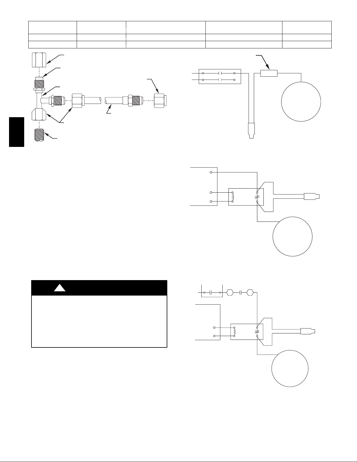
Table 1—Kit Usage and Cut In/Cut Out Pressures
KITPARTNO. REFRIGERANT PRESSURE SWITCH CLOSES
(PSIG)
KSALA0201R22 R --- 2 2 225 100 Blue and Yellow
KSALA0301410 R---410A 365 200 Blue and Violet
PRESSURE SWITCH OPENS
(PSIG)
WIRE COLORS
SERVICE FITTING CAP
VALVE CORE END
FLARE NUT
ON PRESSURE
ADAPTER TEE
EXTENDER TUBE
FLARE NUT
KSALA
LIQUID REFRIGERANT SERVICE
VALVE SERVICE FITTING
SWITCH
Fig. 1 — Low--Ambient Pressure Switch
REQUIRED CHANGES FOR COOLING UNITS AND
HEAT PUMP UNITS
1. Crankcase heaters are required on all applications where
low--ambient controls are used.
2. Start capacitor and relay (hard start) kits are required on all
single--phase applications where low--ambient controls are
used.
3. Evaporator freeze thermostat KAAFT0101AAA is
required on all applications where low-- ambient controls
are used.
4. Wind baffles are required for temperatures below 0_For
where there is substantial wind.
A00025
CONTACTOR
OF2
DEFROST
BOARD
O
C
CONNECTOR
BLACK
FAN
MOTOR
BLUE
PRESSURE
SWITCH
YELLOW
OR
VIOLET
Fig. 2 — Power Wiring for All Voltages of
Cooling Applications
PRESSURE
BLUE
YELLOW
ISOLATION
RELAY
BLACK
OR VIOLET
FAN
MOTOR
A97326
SWITCH
NOTE: When wind baffles are used, raising unit off of pad a
minimum of 4 in. is required to provide better airflow for
moderate-- and high--ambient temperatures. Check pre--sale
literature for available support feet or unit risers.
!
CAUTION
CUT HAZARD
Failure to follow this caution could result in personal
injury.
To reduce risk of personal injury, wear personal protective
equipment when working with wind baffles. Only
experienced technicians should fabricate and install wind
baffles.
5. For cooling applications only, winter start control
KAAWS0101AAA must be used where low--pressure
switch tripping may be encountered. Winter start control
must be wired in parallel with low--pressure switch. This
allows a delay of 3 minutes before low--pressure switch
becomes part of control circuit. (See Fig. 5.)
A97327
Fig. 3 — Power Wiring for 208/230v Heat Pump
Applications
13
OUTDOOR
FAN RELAY
DEFROST
BOARD
O
C
ISOLATION
RELAY
BLACK
BLUE
YELLOW
OR VIOLET
FAN
MOTOR
PRESSURE
SWITCH
A97328
Fig. 4 — Power Wiring for 460v Heat Pump Applications
2
Page 3
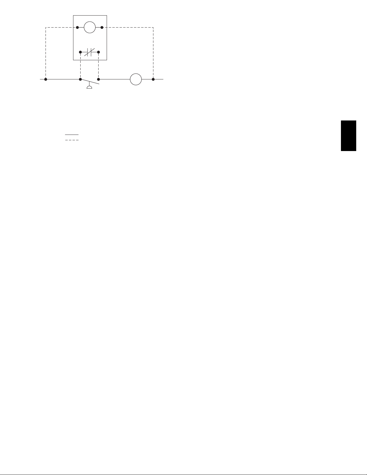
T
TDR
C
LPS
LPS
LOW-PRESSURE SWITCH
C
CONTACTOR COIL
TDR
TIME DELAY RELAY
T
RELAY COIL
FACTORY WIRING
FIELD WIRING
A93165
Fig. 5 — Low Voltage Wiring for Winter Start Control
START--UP
To start units equipped with the low--ambient pressure switch,
perform the following steps:
1. Turn power on to unit.
2. Set thermostat below room temperature.
3. Wait for the unit to start. There may be a 5 --minute delay
in the thermostat or in the outdoor unit.
4. Observe unit operation as described below.
a. The fan will be off when compressor starts.
b. At outdoor temperatures around 0_F, fan may not run
at all.
c. At summer temperatures, fan will start after 10 to 30
sec of compressor operation and may not turn off until
thermostat is satisfied.
d. At outdoor ambients between 80_F and 20_F, fa n w i ll
turn on and off to maintain pressure as shown in Table
1.
KSALA
3
Page 4
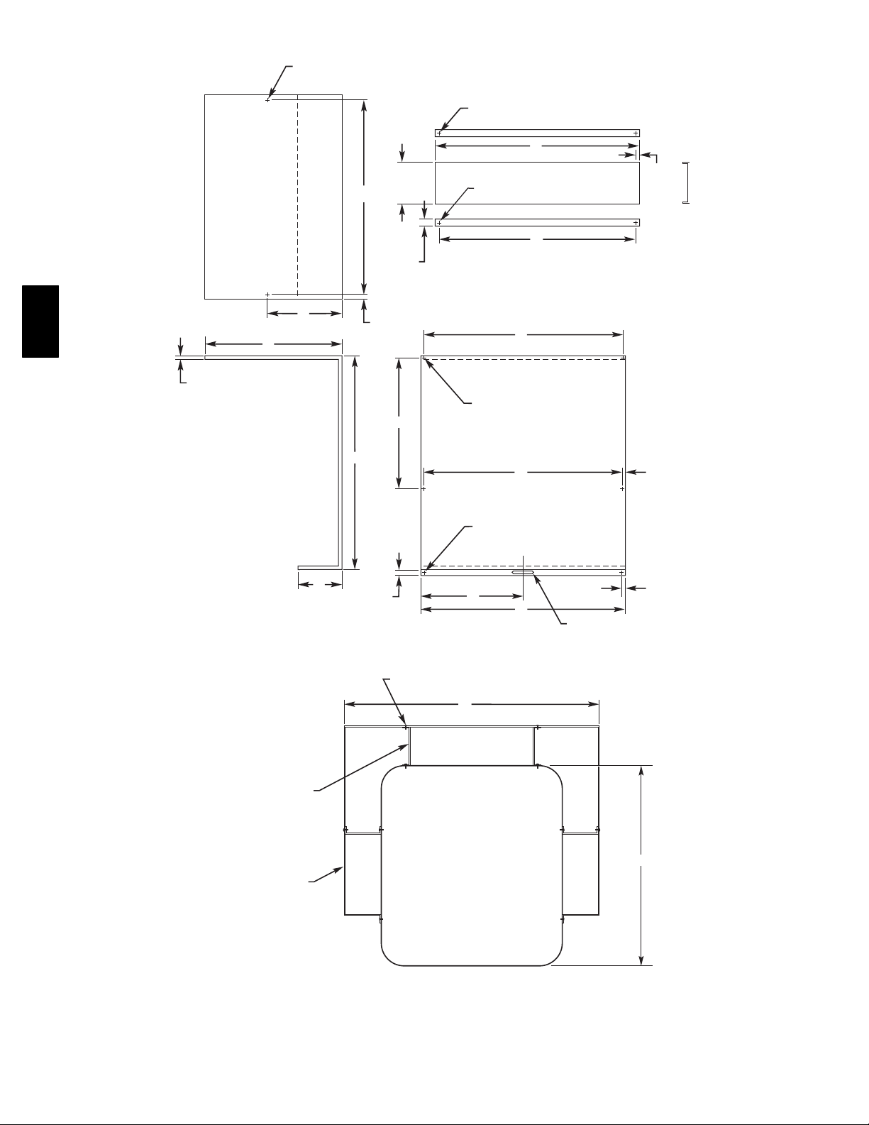
7
/32″ x 3/8″
4 REQ'D
(5.56 x 9.53) SLOT
6
1/16″
(154.0)
J
9
/64″
(3.45) DIA HOLE
2 REQ'D
H
3
/8″
(9.6)
TYP
1
/2″
(12.7)
TYP
7
C
A
1
/2″
(12.7)
TYP
KSALA
/16″
(11.6)
TYP
9
/64″
K
1 REQ'D
B
7
/32″
3 REQ'D
1
M
(6.3)
TYP
/4″
L
BAFFLE
SCREW
10 REQ'D
MAT'L: 20 GA STEEL
F
G
SUPPORT
MAT'L: 18 GA STEEL
E
(3.45) DIA HOLE
J
(5.56) DIA HOLE
D
7
/32″
(5.56 x 50.8) SLOT
x 2
7
/16″
(11.6)
TYP
1
/4″
(6.3)
TYP
″
SUPPORT
4 REQ'D
BAFFLE
2 REQ'D
OUTDOOR
UNIT
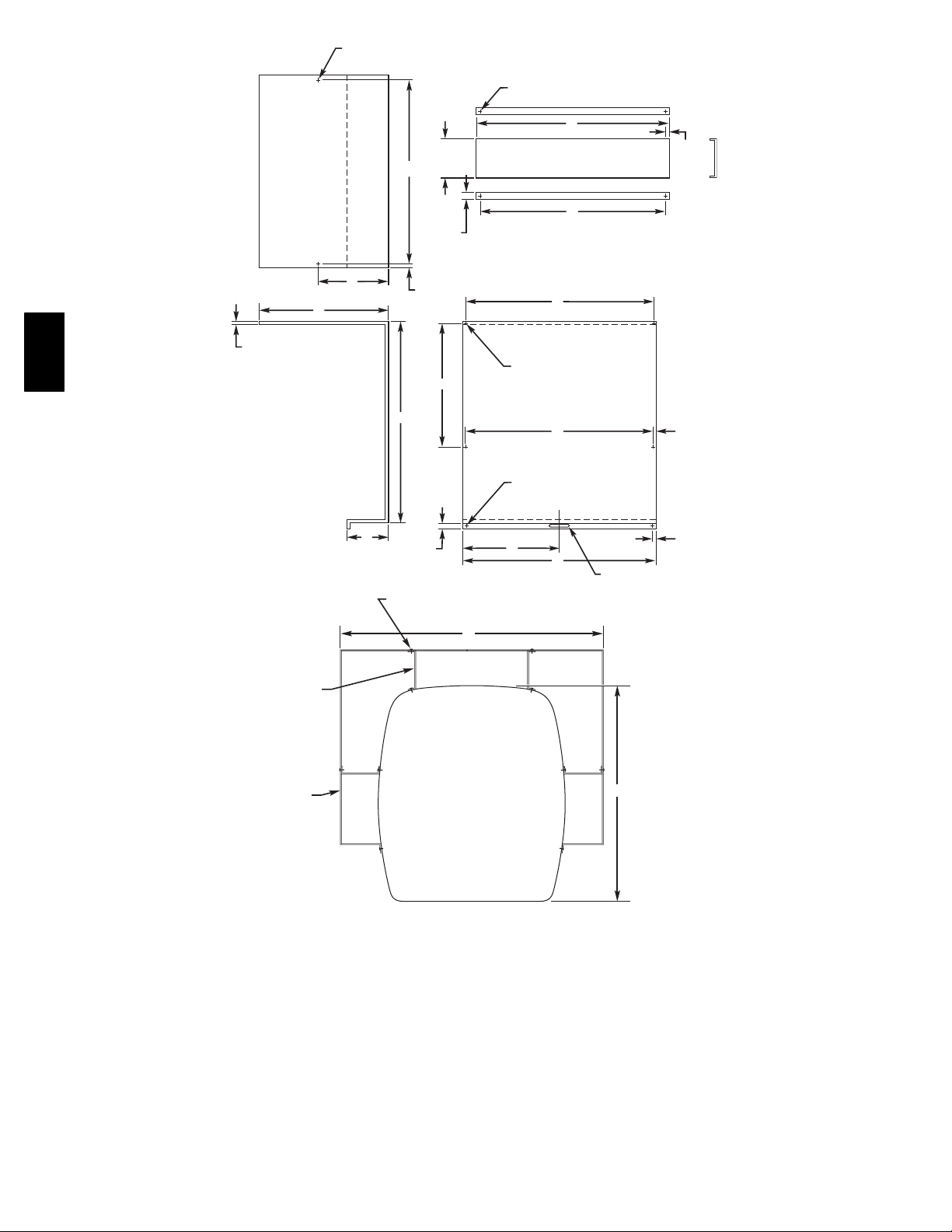
BAFFLE ASSEMBLY
Fig. 6 — Carrier WeatherMaker®Units
AA
A95444
4
Page 5
KSALA
(In.)
A B C D E F G H J K L M
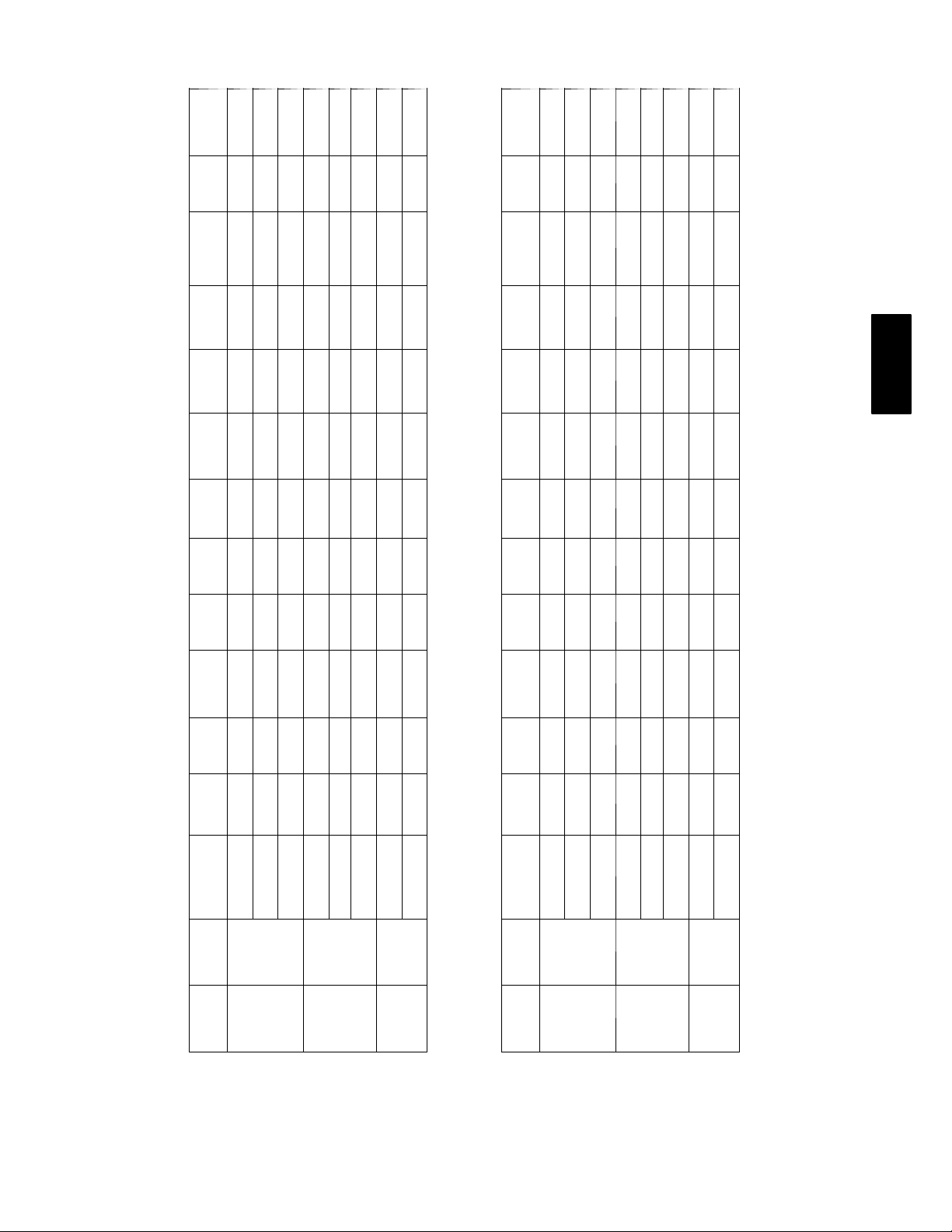
Wind Baffle Dimensions for Carrier WeatherMaker Units—38TKB, 38TKW, 38YKC
Height
21---7/8 17 25---1/4 10 --- 3/8 19--- 3/4 20-- -1/2 34 19--- 11/16 20---7/16 19---5/8 0 0 6 --- 1 / 8
25---7/8 17 25---1/4 10 --- 3/8 23 --- 3/4 24 ---1/2 34 23 ---11/16 24 ---7/16 23---5/8 0 11 --- 7/8 6 --- 1 / 8
31---7/8 17 25---1/4 10 --- 3/8 29 --- 3/4 30 ---1/2 34 29 ---11/16 30 ---7/16 29---5/8 0 14 --- 7/8 6 --- 1 / 8
25---7/8 21 32 11 --- 3/16 23---3/4 24 --- 1/2 42 23 --- 11/16 24---7/16 23---5/8 19 ---11/16 11 --- 7/8 6 --- 11/16
31---7/8 21 32 11 --- 3/16 29---3/4 30 --- 1/2 42 29 --- 11/16 30---7/16 29---5/8 19 ---11/16 14 --- 7/8 6 --- 11/16
37---7/8 21 32 11 --- 3/16 35---3/4 36 --- 1/2 42 35 --- 11/16 36---7/16 35---5/8 19 ---11/16 17 --- 7/8 6 --- 11/16
31---7/8 25---3/16 42 12 --- 15/16 29---3/4 30--- 1/2 50--- 7/16 29--- 11/16 30-- -7/16 29---5/8 22 ---11/16 14--- 7/8 7 ---1/16
37---7/8 25---3/16 42 15 --- 15/16 35---3/4 36--- 1/2 50--- 7/16 35--- 11/16 36-- -7/16 35---5/8 22 ---11/16 17--- 7/8 7 ---1/16
AA Unit
Unit
Size
Small 27---1/2
Medium 34--- 15/16
Large 45
(In.)
A B C D E F G H J K L M
Wind Baffle Dimensions for Carrier WeatherMaker Units with Silencer System Top
Height
23---13/16 17 25---1/4 10 --- 3/8 19 --- 3/4 20 ---1/2 34 19 ---11/16 20 ---7/16 19---5/8 0 0 6 --- 1 / 8
27---13/16 17 25---1/4 10 --- 3/8 23 --- 3/4 24 ---1/2 34 23 ---11/16 24 ---7/16 23---5/8 0 11--- 7/8 6 --- 1 / 8
33---13/16 17 25---1/4 10 --- 3/8 29 --- 3/4 30 ---1/2 34 29 ---11/16 30 ---7/16 29---5/8 0 14--- 7/8 6 --- 1 / 8
27---13/16 21 32 11 --- 3/16 23---3/4 24 --- 1/2 42 23 --- 11/16 24---7/16 23---5/8 19 ---11/16 11 --- 7/8 6 --- 11/16
33---13/16 21 32 11 --- 3/16 29---3/4 30 --- 1/2 42 29 --- 11/16 30---7/16 29---5/8 19 ---11/16 14 --- 7/8 6 --- 11/16
39---13/16 21 32 11 --- 3/16 35---3/4 36 --- 1/2 42 35 --- 11/16 36---7/16 35---5/8 19 ---11/16 17 --- 7/8 6 --- 11/16
33---13/16 25---3/16 42 12 ---15/16 29--- 3/4 30--- 1/2 50 --- 7/16 29 ---11/16 30 ---7/16 29---5/8 22--- 11/16 14---7/8 7 --- 1/16
39---13/16 25---3/16 42 15 ---15/16 35--- 3/4 36--- 1/2 50 --- 7/16 35 ---11/16 36 ---7/16 35---5/8 22--- 11/16 17---7/8 7 --- 1/16
AA Unit
Unit
Size
Small 27---1/2
Medium 34--- 15/16
Large 45
5
Page 6
1
/4″ x 3/8″ (5.56 x 9.53) SLOT
4 REQ'D
5
5/16″
(151.5)
J
1
/8″ (3.45) DIA HOLE
2 REQ'D
H
1
/4″ (5.56) DIA HOLE 2 REQ'D
3
/8″
(9.6)
1
/2″
(12.7)
TYP
7
C
KSALA
1
/2″
(12.7)
A
/16″
(11.6)
K
SUPPORT
MAT'L: 18 GA STEEL
1
/8″ (3.45) DIA HOLE
1 REQ'D
B
1
/4″ (5.56) DIA HOLE
G
E
7
/16″
J
(11.6)
3 REQ'D
6″
(152.4)
1
/4″
(6.3)
BAFFLE
L
D
1
/4″ x 2″
(5.56 x 50.8) SLOT
3
/8″ (9.6)
MAT'L: 20 GA STEEL
SUPPORT
4 REQ'D
BAFFLE
2 REQ'D
SCREW
10 REQ'D
F
OUTDOOR
UNIT
BAFFLE ASSEMBLY
Fig. 7 --- Bryant Reliant®Units
6
AA
A95445
Page 7

KSALA
Wind Baffle Dimensions for 10 Seer Bryant Reliant Units with Star--Burst Top
(In.)
A B C D E F G H J K L
(In.)
A B C D E F G H J K L
Wind Baffle Dimensions for Bryant Reliant Units with AeroQuiet Top
Height
21---7/8 17---1/4 24 ---5/16 10--- 1/4 19--- 3/4 20 ---1/2 34---1/2 19 ---5/8 20---3/8 19---5/8 0 0
25---7/8 17---1/4 24 ---5/16 10--- 1/4 23--- 3/4 24 ---1/2 34---1/2 23 ---5/8 24---3/8 23---5/8 0 11 --- 7/8
31---7/8 17---1/4 24 ---5/16 10--- 1/4 29--- 3/4 30 ---1/2 34---1/2 29 ---5/8 30---3/8 29---5/8 0 14 --- 7/8
25---7/8 21 30---5/8 10--- 1/4 23 ---3/4 24--- 1/2 42 23---5/8 24---3/8 23---5/8 17 --- 1/8 11---7/8
31---7/8 21 30---5/8 10--- 1/4 29 ---3/4 30--- 1/2 42 29---5/8 30---3/8 29---5/8 17 --- 1/8 14---7/8
37---7/8 21 30---5/8 10--- 1/4 35 ---3/4 36--- 1/2 42 35---5/8 36---3/8 35---5/8 17 --- 1/8 17---7/8
31---7/8 25---5/16 39 --- 3/4 10---1/4 29--- 3/4 30 ---1/2 50---9/16 29---5/8 30---3/8 29 --- 5/8 21 --- 11/16 14 --- 7/8
37---7/8 25---5/16 39 --- 3/4 10---1/4 35--- 3/4 36 ---1/2 50---9/16 35---5/8 36---3/8 35 --- 5/8 21 --- 11/16 17 --- 7/8
AA Unit
Unit
Size
Small 26 --- 3/16
Medium 33
Large 42 ---1/16
Height
23---13/16 17--- 1/4 24--- 5/16 10---1/4 19 ---3/4 20---1/2 34---1/2 19-- -5/8 20--- 3/8 19 --- 5/8 0 0
27---13/16 17--- 1/4 24--- 5/16 10---1/4 23 ---3/4 24---1/2 34---1/2 23-- -5/8 24--- 3/8 23 --- 5/8 0 11 ---7/8
33---13/16 17--- 1/4 24--- 5/16 10---1/4 29 ---3/4 30---1/2 34---1/2 29-- -5/8 30--- 3/8 29 --- 5/8 0 14 ---7/8
27---13/16 21 30---5/8 10--- 1/4 23 ---3/4 24 ---1/2 42 23---5/8 24--- 3/8 23--- 5/8 17 --- 1/8 11--- 7/8
33---13/16 21 30---5/8 10--- 1/4 29 ---3/4 30 ---1/2 42 29---5/8 30--- 3/8 29--- 5/8 17 --- 1/8 14--- 7/8
39---13/16 21 30---5/8 10--- 1/4 35 ---3/4 36 ---1/2 42 35---5/8 36--- 3/8 35--- 5/8 17 --- 1/8 17--- 7/8
33---13/16 25---5/16 39 ---3/4 10---1/4 29--- 3/4 30 ---1/2 50---9/16 29---5/8 30---3/8 29 --- 5/8 21 --- 11/16 14 --- 7/8
39---13/16 25---5/16 39 ---3/4 10---1/4 35--- 3/4 36 ---1/2 50---9/16 35---5/8 36---3/8 35 --- 5/8 21 --- 11/16 17 --- 7/8
AA Unit
Unit
Size
Small 26 --- 3/16
Medium 33
Large 42 ---1/16
7
Page 8

7
7
/8″
(200.0)
3
/16″
(4.6)
E
1
/8″
(3.45) DIA
2 REQ'D
3
5
/64″
(128.0)
F
C
1
/2″
(12.7)
TYP
1
/4″ x 3/8″
6 REQ'D
1
/4″
(5.56) DIA
4 REQ'D
OUTDOOR
E
29
7
/32″
BAFFLE - RIGHT
MAT'L: 20 GA STEEL
(5.56 x 9.53) SLOT
AA
C
UNIT
(200.8)
RIGHT
SIDE
SCREW
14 REQ'D
SUPPORT
3 REQ'D
7
7
/8″
(199.9)
C
1
/4″
(6.4)
B
1
/2″
(12.7)
3
5
/64″
(128.0)
25
/64″
(10.0)
BAFFLE - LEFT
MAT'L: 20 GA STEEL
13
/64″
(5.4)
TYP
21
1
/32″
(42.1)
KSALA
1
/4″
(5.56) DIA
2 REQ'D
D
A
1
2
/2″
(63.5)
21
1
/32″
1
/4″ x 3/8″
(5.56 x 9.53) SLOT
(42.1)
6 REQ'D
9
4
/64″
45¡
TYP
(105.2)
23
/64″
(9.2)
5
2
/64″
J
(52.6)
57
4
Ú
″
64
(124.2) TYP
1
/2″
5
8
/64″
(205.3)
TYP
1
/4″
(6.4)
TYP
23
(12.7)
/64″
(9.2)
SUPPORT
1
2
(63.5)
/2″
A
D
1
/4″
(5.56) DIA
2 REQ'D
25
Ú64″
G
(10.0)
LEFT
SIDE
MAT'L: 18 GA STEEL
1
/8″
(3.45) DIA.
4 REQ'D
J
H
BAFFLE ASSEMBLY
Fig. 8 --- Carrier / Bryant / Payne Cube Units with 3/8” Coil Tubing
8
A95446
Page 9

KSALA
(In.)
A B C D E F G H J
Wind Baffle Dimensions for Carri er / Bryant / Payne Cube Units with 3/8” Coil Tubing
Height
21---15/16 19--- 7/8 13 --- 3/4 28---1/8 10 --- 11/16 20 --- 1/4 11---11/16 3 --- 13/16 19 ---13/16 17---13/16
23---15/16 21--- 7/8 13 --- 3/4 28---1/8 10 --- 11/16 20 --- 1/4 11---11/16 3 --- 13/16 21 ---13/16 19---13/16
25---15/16 23--- 7/8 13 --- 3/4 28---1/8 10 --- 11/16 20 --- 1/4 11---11/16 3 --- 13/16 23 ---13/16 21---13/16
27---15/16 25--- 7/8 13 --- 3/4 28---1/8 10 --- 11/16 20 --- 1/4 11---11/16 3 --- 13/16 25 ---13/16 23---13/16
29---15/16 27--- 7/8 13 --- 3/4 28---1/8 10 --- 11/16 20 --- 1/4 11---11/16 3 --- 13/16 27 ---13/16 25---13/16
31---15/16 29--- 7/8 13 --- 3/4 28---1/8 10 --- 11/16 20 --- 1/4 11---11/16 3 --- 13/16 29 ---13/16 27---13/16
33---15/16 31--- 7/8 13 --- 3/4 28---1/8 10 --- 11/16 20 --- 1/4 11---11/16 3 --- 13/16 31 ---13/16 29---13/16
21---15/16 19--- 7/8 18--- 5/16 32---5/8 10--- 11/16 24--- 3/4 16 ---3/16 8 --- 1 / 4 19--- 13/16 17 ---13/16
23---15/16 21--- 7/8 18--- 5/16 32---5/8 10--- 11/16 24--- 3/4 16 ---3/16 8 --- 1 / 4 21--- 13/16 19 ---13/16
25---15/16 23--- 7/8 18--- 5/16 32---5/8 10--- 11/16 24--- 3/4 16 ---3/16 8 --- 1 / 4 23--- 13/16 21 ---13/16
27---15/16 25--- 7/8 18--- 5/16 32---5/8 10--- 11/16 24--- 3/4 16 ---3/16 8 --- 1 / 4 25--- 13/16 23 ---13/16
29---15/16 27--- 7/8 18--- 5/16 32---5/8 10--- 11/16 24--- 3/4 16 ---3/16 8 --- 1 / 4 27--- 13/16 25 ---13/16
31---15/16 29--- 7/8 18--- 5/16 32---5/8 10--- 11/16 24--- 3/4 16 ---3/16 8 --- 1 / 4 29--- 13/16 27 ---13/16
33---15/16 31--- 7/8 18--- 5/16 32---5/8 10--- 11/16 24--- 3/4 16 ---3/16 8 --- 1 / 4 31--- 13/16 29 ---13/16
37---15/16 33--- 7/8 18--- 5/16 32---5/8 10--- 11/16 24--- 3/4 16 ---3/16 8 --- 1 / 4 33--- 13/16 31 ---13/16
39---15/16 35--- 7/8 18--- 5/16 32---5/8 10--- 11/16 24--- 3/4 16 ---3/16 8 --- 1 / 4 35--- 13/16 33 ---13/16
25---15/16 23--- 7/8 25 --- 3/4 40---1/8 10 --- 11/16 32 --- 1/4 23---11/16 15--- 13/16 23 --- 13/16 21 --- 13/16
27---15/16 25--- 7/8 25 --- 3/4 40---1/8 10 --- 11/16 32 --- 1/4 23---11/16 15--- 13/16 25 --- 13/16 23 --- 13/16
29---15/16 27--- 7/8 25 --- 3/4 40---1/8 10 --- 11/16 32 --- 1/4 23---11/16 15--- 13/16 27 --- 13/16 25 --- 13/16
31---15/16 29--- 7/8 25 --- 3/4 40---1/8 10 --- 11/16 32 --- 1/4 23---11/16 15--- 13/16 29 --- 13/16 27 --- 13/16
33---15/16 31--- 7/8 25 --- 3/4 40---1/8 10 --- 11/16 32 --- 1/4 23---11/16 15--- 13/16 31 --- 13/16 29 --- 13/16
35---15/16 33--- 7/8 25 --- 3/4 40---1/8 10 --- 11/16 32 --- 1/4 23---11/16 15--- 13/16 33 --- 13/16 31 --- 13/16
37---15/16 35--- 7/8 25 --- 3/4 40---1/8 10 --- 11/16 32 --- 1/4 23---11/16 15--- 13/16 35 --- 13/16 33 --- 13/16
39---15/16 37--- 7/8 25 --- 3/4 40---1/8 10 --- 11/16 32 --- 1/4 23---11/16 15--- 13/16 37 --- 13/16 35 --- 13/16
43---15/16 41--- 7/8 25 --- 3/4 40---1/8 10 --- 11/16 32 --- 1/4 23---11/16 15--- 13/16 41 --- 13/16 39 --- 13/16
AA Unit
Unit
Size
Small 18
Medium 22--- 1/2
Large 30
9
Page 10

1″
(25.4)
5 5/16″
(134.2)
1
/4″ (6.35) x 1/2″ (12.7) SLOT
(2) REQ'D
7
/16″
(11.8)
1
/2″
(12.7)
3
/8″
(10.3)
H
C
D
E
1
/2″
(12.7)
F
A
1
G
/4″ (6.35) x 3/4″ (19.05) SLOT
(15) REQ'D
7
(11.8)
/16″
1
/2″
(12.7)
3
/8″
(10.3)
B
WIND BAFFLE
KSALA
7
/16″
(11.8)
WIND BAFFLE
BAFFLE
SUPPORT A
1
/2″
(12.7)
3
/8″
(10.3)
1
/8″ (3.45) DIA HOLE
(3) REQ'D
SUPPORT A
1″
(25.4)
″ (25.4) x 3″(76.2)
1
NOTCH (THIS SIDE)
1
(12.7)
(RIGHT AND LEFT HAND REQ'D)
5 5/16″
(134.2)
1
/4″ (6.35) x 1/2″ (12.7) SLOT
(2) REQ'D
7
/16″
(11.8)
(76.2)
3
/8″
(10.3)
/2″
1
/8″ (3.45) DIA HOLE
(3) REQ'D
SUPPORT B
3
1
/2″
(12.7)
/8″
(10.3)
AA
H
3″
J
(11.8)
G
7
/16″
BAFFLE ASSEMBLY
Fig. 9 --- Payne Units—Models PA10 / PA12 and PH10 / PH12
BAFFLE
SUPPORT B
A95447
10
Page 11

KSALA
(In.)
(In.)
Wind Baffle Dimensions for Payne PH10 / PH12 He at Pump Units
21---15/16 18 --- 11/16 9---5/16 81 --- 1/2 67 --- 7/8 41 --- 13/16 15---13/16 18 ---11/16 9 ---5/16 10 ---13/16
23---15/16 20 --- 11/16 10---5/16 81---1/2 67 ---7/8 41 --- 13/16 15---13/16 18 ---11/16 10 ---5/16 10 --- 13/16
25---15/16 22 --- 11/16 11---5/16 81---1/2 67 ---7/8 41 --- 13/16 15---13/16 18 ---11/16 11 ---5/16 10 --- 13/16
27---15/16 24 --- 11/16 12---5/16 81---1/2 67 ---7/8 41 --- 13/16 15---13/16 18 ---11/16 12 ---5/16 10 --- 13/16
29---15/16 26 --- 11/16 13---5/16 81---1/2 67 ---7/8 41 --- 13/16 15---13/16 18 ---11/16 13 ---5/16 10 --- 13/16
31---15/16 28 --- 11/16 14---5/16 81---1/2 67 ---7/8 41 --- 13/16 15---13/16 18 ---11/16 14 ---5/16 10 --- 13/16
33---15/16 30 --- 11/16 15---5/16 81---1/2 67 ---7/8 41 --- 13/16 15---13/16 18 ---11/16 16 ---5/16 10 --- 13/16
23---15/16 20 --- 11/16 10---5/16 107--- 1/16 86 --- 9/16 54--- 11/16 22 --- 3/4 24 - -- 11/16 10 --- 5/16 10--- 13/16
25---15/16 22 --- 11/16 11---5/16 107--- 1/16 86 --- 9/16 54--- 11/16 22 --- 3/4 24 - -- 11/16 11 --- 5/16 10--- 13/16
27---15/16 24 --- 11/16 12---5/16 107--- 1/16 86 --- 9/16 54--- 11/16 22 --- 3/4 24 - -- 11/16 12 --- 5/16 10--- 13/16
29---15/16 26 --- 11/16 13---5/16 107--- 1/16 86 --- 9/16 54--- 11/16 22 --- 3/4 24 - -- 11/16 13 --- 5/16 10--- 13/16
31---15/16 28 --- 11/16 14---5/16 107--- 1/16 86 --- 9/16 54--- 11/16 22 --- 3/4 24 - -- 11/16 14 --- 5/16 10--- 13/16
33---15/16 30 --- 11/16 15---5/16 107--- 1/16 86 --- 9/16 54--- 11/16 22 --- 3/4 24 - -- 11/16 15 --- 5/16 10--- 13/16
35---15/16 32 --- 11/16 16---5/16 107--- 1/16 86 --- 9/16 54--- 11/16 22 --- 3/4 24 - -- 11/16 16 --- 5/16 10--- 13/16
37---15/16 34 --- 11/16 17---5/16 107--- 1/16 86 --- 9/16 54--- 11/16 22 --- 3/4 24 - -- 11/16 17 --- 5/16 10--- 13/16
37---15/16 36 --- 11/16 18---5/16 107--- 1/16 86 --- 9/16 54--- 11/16 22 --- 3/4 24 - -- 11/16 18 --- 5/16 10--- 13/16
21---15/16 18 --- 11/16 9---5/16 81 --- 1/2 67 --- 7/8 41 --- 13/16 15---13/16 18 ---11/16 9 ---5/16 14 ---13/16
23---15/16 20 --- 11/16 10---5/16 81---1/2 67 ---7/8 41 --- 13/16 15---13/16 18 ---11/16 10 ---5/16 14 --- 13/16
25---15/16 22 --- 11/16 11---5/16 81---1/2 67 ---7/8 41 --- 13/16 15---13/16 18 ---11/16 11 ---5/16 14 --- 13/16
27---15/16 24 --- 11/16 12---5/16 81---1/2 67 ---7/8 41 --- 13/16 15---13/16 18 ---11/16 12 ---5/16 14 --- 13/16
29---15/16 26 --- 11/16 13---5/16 81---1/2 67 ---7/8 41 --- 13/16 15---13/16 18 ---11/16 13 ---5/16 14 --- 13/16
31---15/16 28 --- 11/16 14---5/16 81---1/2 67 ---7/8 41 --- 13/16 15---13/16 18 ---11/16 14 ---5/16 14 --- 13/16
33---15/16 30 --- 11/16 15---5/16 81---1/2 67 ---7/8 41 --- 13/16 15---13/16 18 ---11/16 16 ---5/16 14 --- 13/16
23---15/16 20 --- 11/16 10---5/16 107--- 1/16 86 --- 9/16 54--- 11/16 22 --- 3/4 24 - -- 11/16 10 --- 5/16 14--- 13/16
25---15/16 22 --- 11/16 11---5/16 107--- 1/16 86 --- 9/16 54--- 11/16 22 --- 3/4 24 - -- 11/16 11 --- 5/16 14--- 13/16
27---15/16 24 --- 11/16 12---5/16 107--- 1/16 86 --- 9/16 54--- 11/16 22 --- 3/4 24 - -- 11/16 12 --- 5/16 14--- 13/16
29---15/16 26 --- 11/16 13---5/16 107--- 1/16 86 --- 9/16 54--- 11/16 22 --- 3/4 24 - -- 11/16 13 --- 5/16 14--- 13/16
31---15/16 28 --- 11/16 14---5/16 107--- 1/16 86 --- 9/16 54--- 11/16 22 --- 3/4 24 - -- 11/16 14 --- 5/16 14--- 13/16
33---15/16 30 --- 11/16 15---5/16 107--- 1/16 86 --- 9/16 54--- 11/16 22 --- 3/4 24 - -- 11/16 15 --- 5/16 14--- 13/16
35---15/16 32 --- 11/16 16---5/16 107--- 1/16 86 --- 9/16 54--- 11/16 22 --- 3/4 24 - -- 11/16 16 --- 5/16 14--- 13/16
37---15/16 34 --- 11/16 17---5/16 107--- 1/16 86 --- 9/16 54--- 11/16 22 --- 3/4 24 - -- 11/16 17 --- 5/16 14--- 13/16
37---15/16 36 --- 11/16 18---5/16 107--- 1/16 86 --- 9/16 54--- 11/16 22 --- 3/4 24 - -- 11/16 18 --- 5/16 14--- 13/16
Wind Baffle Dimensions for Payne Model PA10 / PA12 Air Conditioning Units
Unit Size AA Unit Height A B C D E F G H J
Medium 22---1/2
Large 30
Unit Size AA Unit Height A B C D E F G H J
Medium 22---1/2
Large 30
11
Page 12

KSALA
Fig. 10 --- Base / Comfortt / Legacyt Units Baffle Assembly
12
A06235
Page 13

KSALA
(In.)
A B C --- 1 C --- 2 C --- 3 D
25 20--- 3/8 10 --- 1/16 3 ---15/16 10---7/8 6 --- 1 / 8 41 ---7/8
Wind Baffle Dimensions for Base / Comfortt / Legacyt Units
Height
Unit Size AA Unit
28---7/16 23 --- 13/16 11--- 3/4 3---15/16 10--- 7/8 6 --- 1 / 8 41--- 7/8
35---1/4 30---5/8 15---3/16 3 ---15/16 10--- 7/8 6 --- 1 / 8 41---7/8
31---13/16 27 --- 3/16 13---1/2 3 ---15/16 10--- 7/8 6 --- 1 / 8 41 ---7/8
Small 25---3/4
42 37--- 3/8 18 --- 9/16 3 ---15/16 10---7/8 6 --- 1 / 8 41 ---7/8
38---5/8 34 16 --- 7/8 3--- 15/16 10---7/8 6 --- 1 / 8 41 --- 7/8
25---1/2 20---3/8 10---1/16 9 --- 3 / 8 16---5/16 11 --- 9/16 47--- 3/8
45---7/16 40 --- 13/16 20--- 1/4 3---15/16 10--- 7/8 6 --- 1 / 8 41--- 7/8
28---15/16 23 ---13/16 11--- 3/4 9 --- 3 / 8 16--- 5/16 11---9/16 47 ---3/8
35---3/4 30---5/8 15---3/16 9 --- 3 / 8 16---5/16 11 --- 9/16 47--- 3/8
39---1/8 34 16 --- 7/8 9 --- 3 / 8 16--- 5/16 11 --- 9/16 47 --- 3/8
32---5/16 27 ---3/16 13--- 1/2 9 --- 3 / 8 16 --- 5/16 11 ---9/16 47--- 3/8
Medium 31 ---1/4
42---1/2 37---3/8 18---9/16 9 --- 3 / 8 16---5/16 11 --- 9/16 47--- 3/8
25---1/2 20---3/8 10---1/16 13 ---3/16 20--- 1/8 15--- 3/8 51---1/8
45---15/16 40 ---13/16 20--- 1/4 9 --- 3 / 8 16--- 5/16 11---9/16 47 ---3/8
28---15/16 23 ---13/16 11--- 3/4 13---3/16 20--- 1/8 15---3/8 51---1/8
35---3/4 30---5/8 15---3/16 13 ---3/16 20--- 1/8 15--- 3/8 51---1/8
39---1/8 34 16 --- 7/8 13--- 3/16 20---1/8 15--- 3/8 51---1/8
32---5/16 27 ---3/16 13--- 1/2 13---3/16 20--- 1/8 15-- -3/8 51---1/8
Large 35
42---1/2 37---3/8 18---9/16 13 ---3/16 20--- 1/8 15--- 3/8 51---1/8
45---15/16 40 ---13/16 20--- 1/4 13---3/16 20--- 1/8 15---3/8 51---1/8
13
Page 14

KSALA
BAFFLE-1
MATL: 20 GA STEEL
A06231
BAFFLE ASSEMBLY
Fig. 11 --- Performancet and Preferredt Series Baffle Assemblies
14
A06230
Page 15

BAFFLE-2
MATL: 20 GA STEEL
KSALA
A06232
BAFFLE-3
MAT'L: 20 GA STEEL
Fig. 12 --- Performancet and Preferredt Series Baffle Assemblies (continued)
15
A06234
Page 16

KSALA
SUPPORT
MAT'L: 20 GA STEEL
Fig. 13 --- Performancet and Preferredt Series Baffle Assemblies (continued)
16
A06233
Page 17

H
(In.)
H
(In.)
G
(In.)
F
(degrees)
E
(In.)
D
(degrees)
C
(In.)
B
(In.)
G
(In.)
F
(degrees)
E
(In.)
D
(degrees)
C
(In.)
B
(In.)
KSALA
A
(In.)
Wind Baffle Dimensions for Performancet Series Units
Height
29---1/2 23--- 13/16 11 --- 7/8 16 81.9 16 --- 3/8 80.3 12--- 3/4 45---7/8
Unit Size AA Unit
39---3/4 34 17 16 81.9 16 ---3/8 80.3 12--- 3/4 45---7/8
43---1/8 37--- 3/8 18 --- 11/16 16 81.9 16 ---3/8 80.3 12---3/4 45 ---7/8
46---1/2 40--- 13/16 20 --- 3/8 16 81.9 16 --- 3/8 80.3 12--- 3/4 45---7/8
36---3/8 27 --- 3/16 13--- 5/8 22 ---5/16 80.2 16---11/16 78.8 17- -- 3/8 51 --- 1/16
36---5/16 30 --- 5/8 15--- 5/16 16 81.9 16---3/8 80.3 12- -- 3/4 45-- -7/8
32---15/16 27--- 3/16 13 ---5/8 16 81.9 16- -- 3/8 80.3 12---3/4 45--- 7/8
Medium 33
32---15/16 23 --- 13/16 11 ---7/8 22 --- 5/16 80.2 16---11/16 78.8 17--- 3/8 51 ---1/16
39---3/4 30--- 5/8 15 ---5/16 22---5/16 80.2 16---11/16 78.8 17---3/8 51--- 1/16
Large 40
43---3/16 34 17 22--- 5/16 80.2 16 ---11/16 78.8 17 ---3/8 51---1/16
46---9/16 37 --- 3/8 18- -- 11/16 22--- 5/16 80.2 16---11/16 78.8 17--- 3/8 51 - -- 1/16
49---15/16 40 --- 13/16 20 ---3/8 22 --- 5/16 80.2 16---11/16 78.8 17--- 3/8 51 ---1/16
A
(In.)
Wind Baffle Dimensions for Preferredt Series Units
30 23---13/16 11--- 7/8 16 81.9 16---3/8 80.3 12---3/4 45 ---7/8
Height
33---7/16 27--- 3/16 13 ---5/8 16 81.9 16--- 3/8 80.3 12---3/4 45--- 7/8
36---13/16 30--- 5/8 15 ---5/16 16 81.9 16 --- 3/8 80.3 12--- 3/4 45---7/8
Unit Size AA Unit
48 40---13/16 20--- 3/8 16 81.9 16---3/8 80.3 12---3/4 45 ---7/8
40---1/4 34 17 16 81.9 16 ---3/8 80.3 12--- 3/4 45---7/8
43---5/8 37--- 3/8 18 --- 11/16 16 81.9 16 ---3/8 80.3 12---3/4 45 ---7/8
Medium 33
34---3/16 23--- 13/16 11 --- 7/8 22---5/16 80.2 16--- 11/16 78.8 17 ---3/8 51---1/16
37---5/8 27 --- 3/16 13--- 5/8 22 ---5/16 80.2 16---11/16 78.8 17- -- 3/8 51 --- 1/16
41 30--- 5/8 15 - -- 5/16 22-- -5/16 80.2 16--- 11/16 78.8 17 --- 3/8 51--- 1/16
Large 40
44---7/16 34 17 22--- 5/16 80.2 16 ---11/16 78.8 17 ---3/8 51---1/16
47---13/16 37--- 3/8 18 --- 11/16 22---5/16 80.2 16---11/16 78.8 17--- 3/8 51 --- 1/16
51---3/16 40--- 13/16 20 --- 3/8 22---5/16 80.2 16--- 11/16 78.8 17 ---3/8 51---1/16
17
Page 18

KSALA
Copyright 2006 CAC / BDP S 7310 W. Morris St. S Indianapolis, IN 46231
Manufacturer reserves the right to change, at any time, specifications a nd desig ns without notice and without obligations.
Printed in U.S.A. Edition Date: 5/06
18
Catalog No: AG-- SALA--0 7
Replaces:AG--SALA--0 5
 Loading...