

Carrier KFCEH2401C05, KFCEH0501N05, KFCEH0901N10, KFCEH2601C10, KFCEH3001F15 Installation Instructions Manual
...Page 1

Installation Instructions
Electric Heater
Packages
NOTE: Read the entire instruction manual before starting the installation.
This symbol → indicates a change since the last issue.
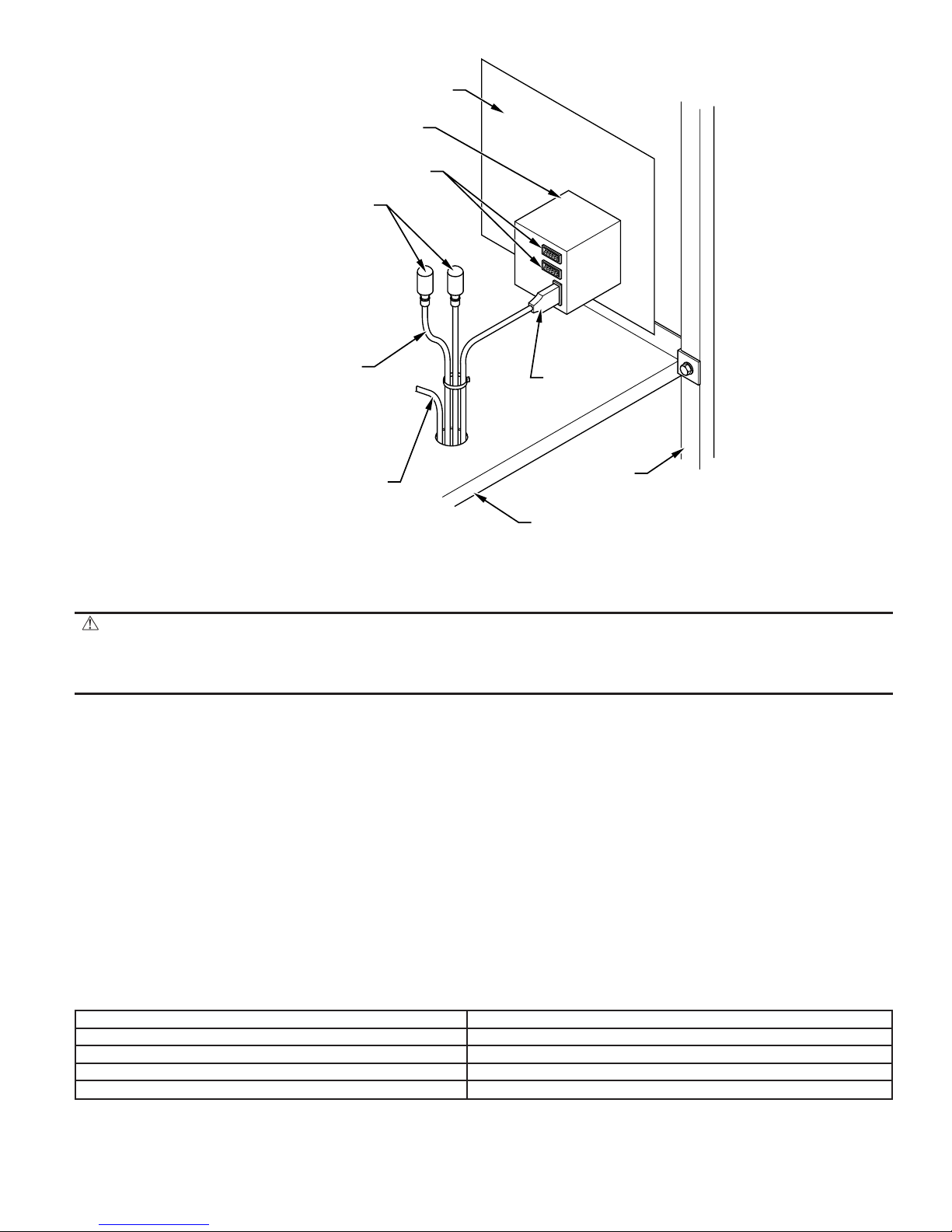
SINGLE-CIRCUIT
GROUND LUG
TERMINAL
BLOCK
MULTI-CIRCUIT
GROUND LUG
KFCEH
(MUST BE REMOVED WHEN
INSTALLING LARGE HEATER)
FUSE BLOCK
(24- AND 30-KW)
FUSE COVER
CLIP LATCH
Fig. 1—Installation of 18-, 24-, and 30-kw Model Heaters
Installing and servicing heating and air conditioning equipment can be hazardous due to system pressures and electrical components. Only trained
personnel should install or service heating and air conditioning equipment.
Untrained personnel can perform basic maintenance functions such as cleaning coils, or cleaning and replacing filters. All other operations should
be performed bytrained service personnel. When working on heating and air conditioning equipment, observe precautions in the literature, on tags,
and on labels attached to the unit.
Follow all safety codes. Wear safety glasses and work gloves. Have a fire extinguisher available.
Recognize safety information. This is the safety-alert symbol
When you see this symbol on the unit and in instructions or manuals, be alert to the potential for personal injury.
Understand the signal words DANGER, WARNING, CAUTION, and NOTE. These words are used with the safety-alert symbol. DANGER
identifies the most serious hazards which will result in severe personal injury or death. WARNING signifies hazards which could result in personal
injury or death. CAUTION is used to identify unsafe practices which would result in minor personal injury or product and property damage. NOTE
is used to highlight suggestions which will result in enhanced installation, reliability, or operation.
WARNING: Before beginning any installation or modification, be sure the main electrical disconnect switch is in the
OFF position. Tag the disconnect switch with a suitable warning label. Electrical shock can cause personal injury or death.
SAFETY CONSIDERATIONS
.
(OMITTED ON 18-KW)
ADAPTER PLATE
A90154
Form: AG-FCEH-09 Cancels: AG-FCEH-08 Printed in U.S.A. 4-03 Catalog No. 63FC-EH7
Page 2

INTRODUCTION
→ Table 1—Accessory Heater Usage
ELECTRIC HEATER
PART NO.
KFCEH0401N03 3 Non-fused 018, 024 024 001 — — NO
KFCEH0501N05
KFCEH2401C05
KFCEH0801N08
KFCEH2501C08
KFCEH2901N09 9* Non-fused 036-071 036-070 002-004 036-060 003-006 YES†
KFCEH0901N10
KFCEH2601C10
KFCEH3001F15
KFCEH2701C15
KFCEH3101C15
KFCEH3201F20
KFCEH2801C20
KFCEH3301C20
KFCEH1601315 15 Non-fused 036-071 036-070 002-004 036-060 001-006 NO
KFCEH2001318 18 Non-fused 042-071 042-070 003, 004 042-060 003-006 NO
KFCEH3401F24
KFCEH3501F302430
† These heaters are Intelligent Heat capable when used with the FK4, FV4, and 40FK fan coils and corporate 2-speed programmable thermostat (TSTATXXP2S01-B),
Thermidistat™ Control (TSTATXXPRH01-B), or capable zoning system.
‡ Field convertible to 1 phase, single or multiple supply circuit.
* Field convertible to 3 phase.
KW
PROTECTION
5
Circuit Breaker
8
Circuit Breaker
10
Circuit Breaker
15
Circuit Breaker
Circuit Breaker
20
Circuit Breaker
Circuit Breaker
INTERNAL
Non-fused
Non-fused
Non-fused
Fused
Fused
Fused
Fused
MODEL FA, FB, PF
SIZE
018-071 024-070 001-004 030-060 001-006
018-071 024-070 001-004 030-060 001-006
018-071 024-070 001-004 030-060 001-006
024-071 024-070 001-004 030-060 001-006
030-071 030-070 002-004 030-060 001-006
048-071 048-070 003, 004 048-060 005, 006
MODEL FC
SIZE
1 Phase
3 Phase Only
3 Phase, Factory Shipped‡
MODEL FH
SIZE
MODEL FX
SIZE
MODEL
FE4, FK4, FV4, 40FK
SIZE
FK, FV, 40FK
INTELLIGENT
HEAT CAPABLE
NO
NO
NO
NO
NO
NO
YES†
YES†
YES†
YES†
YES†
YES†
YES†
YES†
Table 2—Minimum CFM and Motor Speed Selection
FAN COIL
SIZES
FA, FB, FC, FH, FX,
PF
018 525 525 525 — 600* — — — — —
024 700 700 700 700 700 775* — — — —
030, 033 — 875 875 875 875 875 — 1060* — —
036, 038, — 1050 970 970 970 920 — 1040 — —
042 — 1225 1225 1225 1225 1225 1225 1225 — —
048, 054, — 1400 1400 1400 1400 1400 1400 1400 1400 1400
060, 070, — 1750 1750 1750 1750 1750 1750 1750 1750 1750
* Indicates medium speed (blue). All other motor speeds at low tap.
3 5 8 9 10 15 18 20 24 30
HEATER KW
This instruction describes the installation of Part No. KFCEH accessory heaters in FA, FB, FC, FH, FX, and PF1MNB018-070 fan coils and in
the FE4, FK4, FV4, 40FK, and PF1MNA071 fan coils.
NOTE: Electric heaters require a minimum airflow. Minimum airflow and motor speed selection are listed in Table 2. For 3- through 18-kw
standard heaters there are no clearance requirements for the first 36 in. of ductwork. For 20- through 30-kw heaters, a 1-in. clearance is required
for the first 36 in. of ductwork.
INSTALLATION
PROCEDURE 1—INSTALL ELECTRIC HEATER ASSEMBLY
NOTE: Ensure heater coils are not deformed or damaged during heater installation.
1. Make sure power to unit is off.
2. Remove blower access panel of fan coil unit.
CAUTION:
Before installation of heater, the black and yellow pigtail leads must be removed from the fan coil PCB or
wire harness to prevent possible damage to the product. Electrical power will be provided to the board through the heater
circuit plug.
3. Disconnect 2 power wires (black and yellow pigtail leads) from PCB or wire harness (if applicable) and discard. Wires may be part of a
plug assembly or attached to terminals L1 and L2. Remove cooling control plate from fan coil (if equipped). For 18-, 24-, and 30-kw heaters,
remove adapter plate. (See Fig. 1.)
4. Insert heater assembly into front of fan coil so that element rods engage holes in rear heat shield.
5. Attach heater control plate to fan coil using 2 screws provided. For 18-, 24-, and 30-kw heater models, attach front of heater to fan deck
using third screw. (See Fig. 1.)
—2—
Page 3

PROCEDURE 2—ATTACH FUSE BOX OR CIRCUIT BREAKER BOX
1. For 15- and 20-kw fused models:
After installing heater assembly, attach fuse assembly to side of fan coil unit by inserting fuse box tab between insulation and to left side
of unit and fan deck. Mount front of assembly to side flange with 2 screws provided. On fan coil units size 042 and larger, remove wire
tie that shortens wire length between heater and fuses. Fuse cover is closed by engaging dimples in fuse box. (See Fig. 2.)
INSERT FUSE
BOX TAB HERE
SINGLE-CIRCUIT
GROUND LUG
FUSE BOX TAB
DIMPLE
FUSE BOX
DUAL-CIRCUIT
GROUND LUG
COVER PLATE
OR
KNOCKOUT
HEATER/CUTOUT
COVER
WIRE TIE
FUSE COVER
(REMOVE ON
LARGE FAN COILS)
Fig. 2—Installation of Fused Model Heater
2. For 24- and 30-kw fused models:
Fuse assembly is mounted on heater. Be sure fuse cover is closed by engaging clip latch on unit top panel. (See Fig. 1.)
WARNING:
Ensure fuse box is closed before power is turned to ON position. Electrical shock may cause personal
injury or death.
3. For 5- through 20-kw circuit breaker models:
After installing heater assembly, attach circuit breaker assembly to unit with screws provided. (See Fig. 3.) On fan coil units size 042 and
larger, remove wire tie that shortens wire length between heater and circuit breaker assembly to allow mounting of circuit breaker assembly.
(See Fig. 3.)
→
4. Circuit breaker models require installing a window bezel in unit door to provide safe access to circuit breakers. The Window Bezel mounts
on the outside of the blower door. (See Fig. 4.)
→
→
a. Cut insulation away from rectangular access hole in blower access panel.
b. Remove adhesive backing from window bezel and from the outside. Insert the window through the rectangular hole and seat firmly on
the door surface. Press firmly in place to seat the adhesive. (See Fig. 4.)
PROCEDURE 3—ELECTRICAL CONNECTIONS
Refer to unit instructions for recommended wiring procedures. Install wiring in accordance with all applicable local and national codes. (See Tables
3, 4, and 5.)
Connect heater wiring harness plug to receptacle on PCB or wire harness. A positive connection must be made between plug and receptacle. Plug
will interlock with receptacle when properly seated. Harness contains both 24-v control and high-voltage wiring. Blower power is provided through
heater harness.
NOTE: Units with or without electric heaters require a minimum CFM. Refer to unit wiring label to ensure the fan speed selected with electric
heaters is equal to or greater than the minimum fan speed indicated. The minimum CFM for cooling is determined by the outdoor unit requirements.
Use the higher of the 2 for year-round operation.
A90151
—3—
Page 4

208/230v (Ft)‡‡
Max Wire Length
Dual Circuit
Single
Circuit
208/230v (Ft)‡‡
Max Wire Length
Dual Circuit
Single
Circuit
208/230V (FT)‡‡
MAX WIRE LENGTH
208/230v
Max Fuse/Ckt Bkr Amps
BRANCH CIRCUIT
208/230v
Min Gnd Wire Size
208/230v††
Min Wire Size (AWG)
208/230V**
MIN AMPACITY
Dual Circuit
Single
Circuit
Dual Circuit
Single
Circuit
Dual Circuit
Single
Circuit
Dual Circuit
Single
Circuit
208/230v
Max Fuse/Ckt Bkr Amps
BRANCH CIRCUIT
208/230v
Min Gnd Wire Size
208/230v††
Min Wire Size (AWG)
208/230V**
MIN AMPACITY
Dual Circuit
Single
Circuit
Dual Circuit
Single
Circuit
Dual Circuit
Single
Circuit
Dual Circuit
Single
Circuit
208/230V
MAX FUSE/CKT BKR AMPS
208/230V
MIN GND
WIRE SIZE
208/230V††
MIN WIRE SIZE (AWG)
208/230V**
MIN AMPACITY
→ Table 3—Electric Heater Electrical Data
208/230V
HEATER AMPS
CIRCUIT
INTERNAL
PHASE
KW
HEATER PART NO.
Dual Circuit
Single
Circuit
PROTECTION
240v 208v L1,L2 L3,L4 L1,L2 L3,L4 L1,L2 L3,L4 L1,L2 L3,L4 L1,L2 L3,L4 L1,L2 L3,L4
1
KFCEH0401N03 3 2.3 1 None 10.9/12.0 ——15.9/17.3 ——12/12 ——12/12 ——20/20 ——67/68 ——
5 3.8 1 None 18.1/20.0 ——26.0/28.4 ——10/10 ——10/10 ——30/30 ——66/66 ——
5 3.8 1 None 18.1/20.0 ——31.2/33.5 ——8/8 ——10/10 ——35/35 ——85/88 ——
5 3.8 1 Ckt Bkr 18.1/20.0 ——31.2/33.5 ——8/8 ——10/10 ——35/35 ——85/88 ——
2
2
KFCEH2501C08 8 6.0 1 Ckt Bkr 28.9/32.0 ——44.7/48.5 ——8/8 ——10/10 ——45/50 ——59/60 ——
KFCEH2401N08 8 6.0 1 None 28.9/32.0 ——44.7/48.5 ——8/8 ——10/10 ——45/50 ——59/60 ——
KFCEH0501N05
KFCEH2401C05
KFCEH0501N05
KFCEH0901N10 10 7.5 1 None 36.2/40.0 ——53.8/58.5 ——6/6 ——10/10 ——60/60 ——78/80 ——
KFCEH2601C10 10 7.5 1 Ckt Bkr 36.2/40.0 ——53.8/58.5 ——6/6 ——10/10 ——60/60 ——78/80 ——
KFCEH2901N09‡ 9 6.8 3 None 18.8/20.8 ——32.0/34.5 ——8/8 ——10/10 ——35/35 ——83/85 ——
KFCEH2901N09*** 9 6.8 1 None 32.8/36.0 ——49.5/53.5 ——8/6 ——10/10 ——50/60 ——54/87 ——
KFCEH3001F15*** 15 11.3 1 Fuse 54.2/59.9 36.2/40.0 18.1/20.0 76.3/83.4 53.8/58.5 22.7/25.0 4/4 6/6 10/10 8/8 10/10 10/10 80/90 60/60 25/25 88/89 78/80 75/76
15 11.3 1 Ckt Bkr — 36.2/40.0 18.1/20.0 — 53.8/58.5 22.7/25.0 — 6/6 10/10 — 10/10 10/10 — 60/60 25/25 — 78/80 75/76
KFCEH1601315 15 11.3 3 None 31.3/34.6 ——47.7/51.8 ——8/6 ——10/10 ——50/60 ——56/90 ——
KFCEH2001318 18 13.5 3 None 37.6/41.5 ——55.5/60.4 ——6/6 ——10/8 ——60/70 ——76/77 ——
KFCEH2701C15***
KFCEH3201F20*** 20 15.0 1 Fuse 72.3/79.9 36.2/40.0 36.2/40.0 98.9/108.4 53.8/58.5 45.3/50.0 3/2 6/6 8/8 8/6 10/10 10/10 100/110 60/60 50/50 85/109 78/80 59/59
KFCEH3101C15***
20 15.0 1 Ckt Bkr — 36.2/40.0 36.2/40.0 — 53.8/58.5 45.3/50.0 — 6/6 8/8 — 10/10 10/10 — 60/60 50/50 — 78/80 59/59
KFCEH2801C20***
30 22.5 3 Fuse 62.6/69.2 ——86.8/95.0 ——3/3 ——8/8 ——90/100 ——97/98 ——
24 18.0 3 Fuse 50.1/55.4 ——71.2/77.8 ——4/4 ——8/8 ——80/80 ——94/95 ——
24 18.0 1 Fuse 86.7/95.5 ——116.9/127.9 ——1/1 ——6/6 ——125/150 ——115/116 ——
KFCEH3301C20***
KFCEH3501F30†***
KFCEH3401F24†***
Table 4—Smart Heat Electrical Data
30 22.5 1 Fuse 109.0/120.0 ——144.8/158.5 ——0/00 ——6/6 ——150/175 ——117/150 ——
208/230V
HEATER AMPS
CIRCUIT
INTERNAL
PHASE
KW
HEATER PART NO.
Dual Circuit
Single
Circuit
PROTECTION
240v 208v L1,L2 L3,L4 L1,L2 L3,L4 L1,L2 L3,L4 L1,L2 L3,L4 L1,L2 L3,L4 L1,L2 L3,L4
KFCEH0101H10 9 6.8 1 None 32.5/35.9 ——44.0/48.3 ——8/8 ——10/10 ——45/50 ——60/61 ——
KFCEH0201H15 15 11.3 1 Fuse 54.2/59.9 39.7/43.9 14.4/16.0 73.2/80.3 49.7/54.9 23.4/25.4 4/4 8/6 10/10 8/8 10/10 10/10 80/90 50/60 25/30 92/92 53/85 73/74
KFCEH0301H20 20 15.0 1 Fuse 72.3/79.9 36.2/40.0 36.2/40.0 97.2/106.7 52.0/56.8 45.3/50.0 3/2 6/6 8/8 8/6 10/10 10/10 100/110 60/60 50/50 87/111 81/82 93/93
Table 5—Field Multipoint Wiring or 24- and 30-Kw Single Phase
HEATER AMPS
KW
208/230V
PHASE
240V 208V L1,L2 L3,L4 L5,L6 L1,L2 L3,L4 L5,L6 L1,L2 L3,L4 L5,L6 L1,L2 L3,L4 L5,L6 L1,L2 L3,L4 L5,L6
HEATER PART NO.
KFCEH3401F24† 24 18.0 1 28.9/32.0 28.9/32.0 28.9/32.0 44.7/48.5 36.2/40.0 36.2/40.0 8/8 8/8 8/8 10/10 45/50 40/40 40/40 59/60 73/73 73/73
KFCEH3501F30† 30 22.5 1 36.2/40.0 36.2/40.0 36.2/40.0 53.8/58.5 45.3/50.0 45.3/50.0 6/6 8/8 8/8 10/10 60/60 50/50 50/50 78/80 59/59 59/59
† Field convertible to 1 phase, single or multiple supply circuit.
‡ Field convertible to 3 phase.
(ANSI/NFPA 70).
** Includes blower motor amps of largest fan coil used with heater.
†† Copper wire must be used. If other than uncoated (non-plated), 75°C ambient, copper wire (solid wire for 10 AWG and smaller, stranded wire for larger than 10 AWG) is used, consult applicable tables of the National Electric Code
‡‡ Length shown is as measured 1 way along wire path between unit and service panel for a voltage drop not to exceed 2%.
*** Heaters are Intelligent Heat capable when used with the FK4, FV4, and 40FK fan coils and corporate 2-speed programmable thermostat (TSTATXXP2S01-B), or Thermidistat™ Control (TSTATXXPRH01-B).
2. For fan coil sizes 042-060 and all FE4, FK4, FV4, 40FK sizes.
3. Single circuit application of F15 and F20 heaters requires single-point wiring kit accessory.
NOTES: 1. For fan coil sizes 018-036.
—4—
Page 5

DUAL CIRCUIT
GROUND LUG
LINE SIDE
CONNECTION
FAN
COIL
COVER
PLATE
WIRE ROUTING
LOAD SIDE
MOUNTING
BRACKET
WIRE TIE
(REMOVE ON
LARGER UNITS)
Fig. 3—Installation of Circuit Breaker Model Heater
SINGLE
CIRCUIT
GROUND
BLOWER
SHELF
WIRES TO
HEATER
A90153
→ Fig. 4—Installation of Window Bezel for Circuit Breaker Model Heater
A. Wire 24-v Control Systems
1. Connections to unit
Use No. 18 AWG color-coded, insulated (35° C minimum) wire to make low-voltage connections between thermostat, fan coil unit, and
outdoor unit. If thermostat is located more than 100 ft from unit (as measured along the low-voltage wire), use No. 16 AWG color-coded,
insulated (35° C minimum) wire. All wiring must be separated from line voltage power leads. Refer to outdoor unit wiring instructions for
additional wiring procedure recommendations.
2. Transformer
Transformer is factory wired for 230-v operation. For 208-v applications, disconnect black wire on transformer 230-v terminal and
reconnect it to 208-v terminal. (See Fig. 5.) The secondary circuit of transformer is protected by a 5-amp fuse mounted on PCB.
CAUTION: On FA, FB, FC, FH, FX, or PF1MNB018-070 if W2, W3, and E are individually connected on any 3 stage
heater (18, 20 24, 30 kw), as with outdoor thermostats or any other situation, an emergency heat relay must be used. This
relay is in kit Part No. KHAOT0201SEC and is normally used with kit Part No. KHAOT0301FST for 2 outdoor thermostat
systems.
A03069
—5—
Page 6

SECONDARY
C
BRN
RED
208
230
YEL
BLK
PRIMARY
A94067
Fig. 5—Connection of Transformer
3. Heater staging
The units are shipped circuited for single-stage operation. Use outdoor thermostat kit Part No. KHAOT0301FST for 2-stage operation. Use
both kit Part No. KHAOT0201SEC and KHAOT0301FST for 3-stage operation. When 2-stages are desired, cut W3 at the W2 wire nut,
strip and reconnect per wiring staging layout in Installation Instructions for fan coils.
a. The 3-, 5-, 8-, and 10-kw heaters are single stage only.
b. The 9- and 15-kw heaters are adaptable for 2-stage operation.
c. The 18-, 20-, 24-, and 30-kw heaters are adaptable for 3-stage operation.
4. Intelligent Heat Staging
40FK, FK4, and FV4 Fan Coils are capable of Intelligent Heat Staging when installed with capable electric heaters (See Table 1) and a
corporate 2-speed programmable thermostat (TSTATXXP2S01-B), Thermidistat™ Control (TSTATXXPRH01-B), or Comfort Zone
II/Zone Perfect Plus. Consult the fan coil Installation and Set-up Instructions for wiring details. Do not install with outdoor thermostats when
installing for Intelligent Heat Staging.
5. Rectifier and Time Delay Boards
Each heater element is controlled by a relay mounted on the heater panel. The relay has a 24v DC coil. Each relay has a small rectifier board
attached directly to relay coil terminals. The rectifier board converts incoming 24v AC control signal to DC. Some heaters may have up
to three relays. The second and/or third relay rectifier board also has a time delay feature and a small jumper wire built into it. With the
jumper uncut, the time delay allows the second stage heat to be energized approximately 5 sec after the first stage. On 18, 24, and 30kw
heaters, the third stage relay board jumper is cut at factory. This provides an 8 sec delay after first stage relay closes.
B. Power Connections
NOTE: Heater supply circuit wire size and overcurrent protection must comply with National Electrical Code (NEC) and UL branch circuit
requirements. (See Table 3, 4, and 5.) Wires and overcurrent protection, integral to the heater, are not required to meet branch circuit requirements.
Internal circuit protection of 60 amps (maximum) is acceptable.
1. Unprotected heaters: (See Fig. 6, 10, and 11.)
a. The 5- through 10-kw single-phase and 15- and 18-kw 3-phase heaters can be wired for single-supply circuit only. Supply circuit
connects to heater pigtail leads (terminal block on 18-kw heaters).
b. The 3- through 10-kw single-phase heaters can use a separate field-installed, factory-authorized disconnect kit which installs in fan coil.
NOTE: Refer to wiring label for component locations.
c. The 9-kw heater is factory wired for single supply circuit, single phase. To convert heater to single supply circuit, 3 phase:
(1.) Disconnect blue wire from limit switch (LS3). Cut, strip, and connect to field wire L3.
(2.) Disconnect yellow wire from LS1 and connect to LS3.
(3.) Disconnect blue wire from relay 2 terminal 2 and connect to LS1.
2. Circuit breaker heaters: (See Fig. 7 and 9.)
a. The 3- through 10-kw heaters can be wired for single-supply circuit only.
b. The 15- and 20-kw heaters can be wired for dual-supply circuits only.
—6—
Page 7

3. Fused heaters: (See Fig. 8, 12, 13, and 14.)
a. The 15- and 20-kw heaters can be wired for single- or dual-supply circuits. Single-supply circuit wiring requires a factory-authorized,
single-point adapter kit.
b. The 24- and 30-kw heaters can be wired for single- or multiple-supply circuits. Heaters are factory wired for single circuit 3 phase. To
convert heaters to single circuit single phase, disconnect yellow lead from L3 and connect to L1. Disconnect black lead from L3 and
connect to L2. To convert heaters to multiple-supply circuit single phase, remove and discard leads between single-circuit terminal block
and fuse block. Remove and discard single-circuit terminal block. Attach L1 through L6 power leads as indicated on label next to fuse
block.
Field
Power
Wiring
Field
Ground
Wiring
Fig. 6—3, 5, 8, 9, 10kw Non-fused Heaters
L4
L2
L1
Wiring
Field Power
L3
Field Ground
Wiring
Field Ground
Wiring
L1
L2
Ground
Lug
(9kw is field convertible to 3-phase.
See Procedure 3. B. 1. c.)
Circuit 1 : L1-L2
Circuit 2 : L3-L4
Ground lug
Ground lug
Yellow
Black
A00076
Field
Power
Wiring
Field
Ground
Wiring
L1
L2
L3
Wiring
Field Power
L4
Field Ground
Wiring
Field Ground
Wiring
L1
ON
OFF
L2
Ground
Lug
Fig. 7—5, 8, 10kw Circuit Breaker
and Disconnect Heaters
ON
OFF
ON
OFF
Circuit 1 : L1-L2
Circuit 2 : L3-L4
Ground lug
Ground lug
A00077
Fig. 8—15 and 20kw Fused Heaters
(15 and 20kw fused heaters are factory wired for dual
supply circuits. Single supply circuit is possible
with approved single point wiring kit.)
Fig. 9—15 and 20kw Circuit Breaker Heaters
A00079
A00078
—7—
Page 8

L1
Yellow
L1
Field
Power
Wiring
Field
Ground
Wiring
Field
Power
Wiring
L1
L2
L3
Field Ground
Wiring
L2
L3
Fig. 10—15kw 3-Phase Heater
Ground lug
Fig. 12—24 and 30kw Heaters
(3-Phase Wiring Factory Supplied)
Black
Blue
Ground lug
A00080
A00082
Field
Power
L2
Wiring
L3
Field
Ground
Wiring
Fig. 11—18kw 3-Phase Heater
Field
Power
Wiring
L1
L2
Field Ground
Wiring
Fig. 13—24 and 30kw Heaters
(Single Phase, Single Supply Circuit-Field Modified)
Ground lug
A00081
Ground lug
A00083
Field
Power
Wiring
Field Ground
Wiring
Field Ground
Wiring
Field Ground
Wiring
(Single Phase, Multiple Supply Circuits-Field Modified)
L5
L3
L1
L6
L4
L2
Fig. 14—24 and 30kw Heaters
—8—
Circuit 1:L1-L2
Circuit 2:L3-L4
Circuit 3:L5-L6
Ground lug
Ground lug
Ground lug
A00084
Page 9
SINGLE SPADE
INSULATING CAP (2)
MOTOR SPEED
TAP LEADS
2 OR 3
FAN RELAY
PCB
SPEED TAP
TERMINAL
COMMON YELLOW
WRAPPER
FAN DECK
A94068
Fig. 15—Motor Speed Tap and Fan Relay
C. Ground Connections
WARNING: According to NEC, ANSI/NFPA 70, and local codes, cabinet must have an uninterrupted or unbroken
ground to minimize personal injury if an electrical fault should occur. The ground may consist of electrical wire or metal
conduit when installed in accordance with existing electrical codes. (See Ground/Conduit Note below.) Failure to follow this
warning could result in an electric shock, fire, or death.
NOTE: Use UL-listed conduit and conduit connector for connecting supply wire(s) to unit to obtain proper grounding. If conduit connection uses
reducing washers, a separate ground wire must be used. Grounding may also be accomplished by using grounding lugs provided in control box.
1. For unprotected or single-circuit heaters, 1 equipment ground connection is provided on fan coil unit. (See Fig. 1 or 2.)
2. For 15- and 20-kw circuit breaker heaters, an additional ground lug is provided on circuit breaker mounting bracket for dual-circuit
grounding. (See Fig. 3.)
3. For 15- and 20-kw fused heaters, an additional ground lug is provided on fuse mounting bracket for dual-circuit grounding. (See Fig. 2.)
4. For 24- and 30-kw fused heaters, 2 additional ground lugs are provided for single-phase, multicircuit wiring. (See Fig. 1.)
D. Fan Speeds for FA, FB, FC, FH, FX, PF1MNB018—070 Fan Coils
1. Speed tap selection is done at fan relay. To change motor speeds, disconnect fan lead on relay and replace with motor speed tap desired.
Save insulating cap and place on motor lead that was removed from relay. (See Fig. 15.) Refer to Table 6 for further clarification of speed
tap selections.
E. FK4, FE4, FV4, 40FK, PF1MNB071
1. Refer to Table 7 and 8 for minimum CFM and airflow delivery.
Table 6—Color Code for Motor Lead Wires FA, FB, FC, FH, FX, PF1MNB018—070 Units
MOTOR SPEED TAP WIRE COLOR
Common Yellow
High Black
Medium Blue (Factory selected)
Low Red (Blue on 2-speed models)
—9—
Page 10

60
OFF
RELEASE T AB
A99094
Fig. 16—Conversion of Circuit Breaker
PROCEDURE 4—CONVERSION OF CIRCUIT BREAKER FOR DOWNFLOW APPLICATIONS
1. Tag and disconnect factory wiring from terminals on circuit breaker(s).
2. Pull white plastic release tab on the bottom of circuit breaker straight out to release circuit breaker from bracket. (See Fig. 16.)
3. Remove quick connect adapters from factory side of breaker(s). Reinstall adapters on other end of breakers(s). Be sure adapter is located
between lug screw and plate. Torque lug screw to 30-in-.lb.
4. Rotate breaker 180 degrees from its original position and reinstall in bracket. Slide breaker slot into sheet metal tab and snap breaker into
place. Make sure both tabs engage breaker. Reconnect wiring on opposite end. Make sure wires are positioned as before.
5. Remount circuit breaker bracket into unit so that the switch will be in UP position when ON.
PROCEDURE 5—ATTACH WIRING DIAGRAM AND RATING LABEL
Attach heater rating label included with kit over existing electrical information label located on front access panel of fan coil. (See Fig. 17.) If kit
contains multiple rating labels, ensure correct label is applied (check phase and supply circuits).
ON FA, FB, FC, FH, FX, AND PF1MNB018-070 MODELS, PLACE WIRING DIAGRAM LABEL 1 INCLUDED WITH KIT OVER
EXISTING UNIT WIRING DIAGRAM LOCATED ON BLOWER HOUSING. DISCARD WIRING DIAGRAM LABELS1&2.
ON MODEL FK4, FV4, 40FK OR PF1MNB071 PLACE WIRING DIAGRAM LABEL 2 INCLUDED WITH KIT OVER EXISTING UNIT
WIRING DIAGRAM. DISCARD WIRING DIAGRAM LABELS1&3.
ON MODEL FE4, AFFIX WIRING DIAGRAM LABEL 3, INCLUDED WITH KIT, ON BLOWER HOUSING ABOVE FAN COIL WIRING
LABEL. DISCARD WIRING DIAGRAM LABELS1&2.
PROCEDURE 6—VERIFY INSTALLATION
After completion of heater installation, check wiring to ensure tightness and that proper connections and routings have been made. Ensure all
electrical covers are in place and proper labels have been applied. Reinstall blower access panel before turning unit power on.
—10—
Page 11

UNIT RATING
LABEL ON DOOR
HEATER LABEL
FROM KIT
Fig. 17—Heater Rating Label Location
Table 7—FK4C, FV4A, 40FK, PF1MNB071 Airflow Delivery (CFM) - Electric Heating Modes
FAN
UNIT
SIZE
001
002
003
UNIT
FAN
SIZE
005
006
071
* Airflow not recommended for heater/system size.
NOTE: LO, NOM, and HI refer to AC/HP CFM ADJUST selection.
OUTDOOR
UNIT
CAPACITY
BTUH
LO NOM HI LO NOM HI LO NOM HI LO NOM HI
0—50—10 0—15 0—20
18,000 625 625 625 675 675 675 * * * * * *
24,000 650 725 835 * 725 835 875 875 875 * * *
30,000 815 905 1040 * 905 1040 900 900 1040 1100 1100 1100
36,000 980 1085 1250 980 1085 1250 980 1085 1250 1100 1100 1250
24,000 675 725 835 875 875 875 * * * * * *
30,000 815 905 1040 875 905 1040 1100 1100 1100 * * *
36,000 980 1085 1250 980 1085 1250 1100 1100 1250 1225 1225 1250
42,000 1140 1270 1460 1140 1270 1460 1140 1270 1460 1225 1270 1460
OUTDOOR
UNIT
CAPACITY
BTUH
LO NOM HI LO NOM HI LO NOM HI LO NOM HI
0—10 0—15 0—20 0—30
30,000 975 975 1040 1100 1100 1100 * * * * * *
36,000 980 1085 1250 1100 1100 1250 1250 1250 1250 * * *
42,000 1140 1270 1460 1140 1270 1460 1250 1270 1460 1500 1500 1500
48,000 1305 1450 1665 1305 1450 1665 1305 1450 1665 1500 1500 1665
36,000 1100 1100 1250 1350 1350 1350 * * * * * *
42,000 1140 1270 1460 1350 1350 1460 1525 1525 1525 * * *
48,000 1305 1450 1665 1350 1450 1665 1525 1525 1665 1750 1750 1750
60,000 1630 1810 2085 1630 1810 2085 1630 1810 2085 1750 1810 2085
A96251
ELECTRIC HEATER KW RANGE
ELECTRIC HEATER KW RANGE
—11—
Page 12

MODEL
FE4A
002
003
Table 8—FE4A Fan Coil Airflow Delivery (cfm) -- Electric Heating Modes
OUTDOOR
UNIT
CAPACITY
BTUH
3,5 8,9,10 15 18,20
EMERGENCY 625 650 825 1025
18,000 650 650 -- -24,000 675 775 900 -30,000 850 950 1050 1125
36,000 1000 1050 1125 1225
EMERGENCY 675 725 850 1100
24,000 675 875 900 -30,000 850 950 1100 1150
36,000 1025 1075 1150 1275
42,000 1150 1200 1300 1400
ELECTRIC HEATER KW RANGE
MODEL
FE4A
OUTDOOR
UNIT
CAPACITY
BTUH
3,5 8,9,10 15 18,20 24,30
ELECTRIC HEATER KW RANGE
EMERGENCY 675 725 850 1100 1600
30,000 850 950 1100 1150 --
005
36,000 1025 1075 1150 1275 -42,000 1150 1200 1300 1400 -48,000 1325 1325 1400 1500 1600
EMERGENCY 1050 1050 1050 1100 1750
36,000 1150 1150 1350 1350 --
006
42,000 1150 1150 1350 1575 -48,000 1325 1325 1400 1500 1750
60,000 1650 1650 1650 1750 1750
Table 9—FK4D, FE4A, FV4B, 40FK, PF1MNB071 Minimum CFM for Electric Heater Application (CFM) - Electric Heating Modes
FAN
COIL
UNIT
HEAT PUMP
UNIT
SIZE
5 8, 9, 10 15 18, 20 24, 30
Heater Only 625 625 725 875 —
001
002
018 625 625 —— —
024 650 725 875 ——
030 800 875 875 1040 —
036 970 970 970 1040 —
Heater Only 675 700 850 1050 —
024 675 875 875 ——
003
030 800 875 1100 1150 —
036 975 975 1100 1225 —
042 1125 1125 1125 1225 —
Heater Only 675 700 850 1050 1400
030 800 875 875 1150 —
005
036 975 975 1100 1225 —
042 1125 1125 1125 1225 —
048 1305 1305 1305 1305 1400
Heater Only 1050 1050 1050 1050 1750
006
071
036 1100 1100 1350 1350 —
042 1125 1125 1350 1350 —
048 1300 1300 1350 1465 1750
060 1625 1625 1625 1750 1750
NOTES:
1. Heater Only—Air conditioner with electric heater application.
2. These airflows are minimum acceptable airflows as UL listed. Actual airflow delivered will be per airflow delivery chart for Electric Heating Modes.
CFM
HEATER SIZE KW
© 2003 CAC/BDP 7310 W. Morris St., Indianapolis, IN 46231
agfceh09
—12—
Book/Tab 1/3d, 4/2e Catalog No. 63FC-EH7
 Loading...