

Carrier KC SERIES, 73KC*051D, 73KC*061P, 73KC*081P Owner's Manual
SERIES
KC
OWNER'S GUIDE
Have a question? Need help?
Call 1-800 C.a_RRIER in the USA. only
For future reference, filI in the information below and
keep this guide in a safe place Please keep a copy of
your receipt fbr warranty purposes
This book is for 73KC 051D mechanical control air con-
ditioners and 7:fI{C 061P and 7gI(C 081P electronic
control i'oom air conditioners
DEALER NAME
ADDRESS
TELEPHONE
MODEL CATALOG NUMBER
SERVICE DISCRETE 1NXTMBER
SERIAL NUMBER
PLEASE KEEP A (OPY OF YOUR RE( EIPT FOR WARRANTY PURPOSES.
CONTENTS
Page
A FEWWORDS ABOUT YOUR NEW
AIR CONDITIONING UNIT ...................... 2
REQUIRED TOOLS .................................. 2
INSTALLATION .................................. 3-6
UNPACK THE AIR CON_)ITIONER .............. 3
WIRING ........................................... 3
POWER SUPPLY CORD ......................... 3
LOCATION ................................... 4
WINDOYV INSTALLATION ........................ 4
STORM WINDO_ APPLICATIONS ................ 6
OPERATION ...................................... 6-9
MECHANTCAL CONTROLS ....................... 7
ELECTRONIC CONq ROLS ......................... 7
ENERGY S,agvqNG TIPS ............................ 8
Page
MAINTENANCE .................................... 9
CLEAN FILTER ................................... 9
CLEAN FRONT PANEL ........................... 9
CLEAN BASEPAN ................................ 9
CARE OF THE REMOTE CONTROL ............... 9
REMOTE CONTROL BATTERY
REPLACEMENT ................................ 9
TROUBLESHOOTING .......................... 10-12
KCSERIES I
A FEW WORDS
ABOUT YOUR NEW
AIR CONDITIONING UNIT
Thank you for choosing a Carrier room air conditioner
to cool 3_ur home or office In addition to providing
economical cooling comfort, Carrier room air condi-
tioners filter and dehumidify" the air in the room
This owner's guide will supply all the information you
need to install, operate, and maintain 5_ur new air
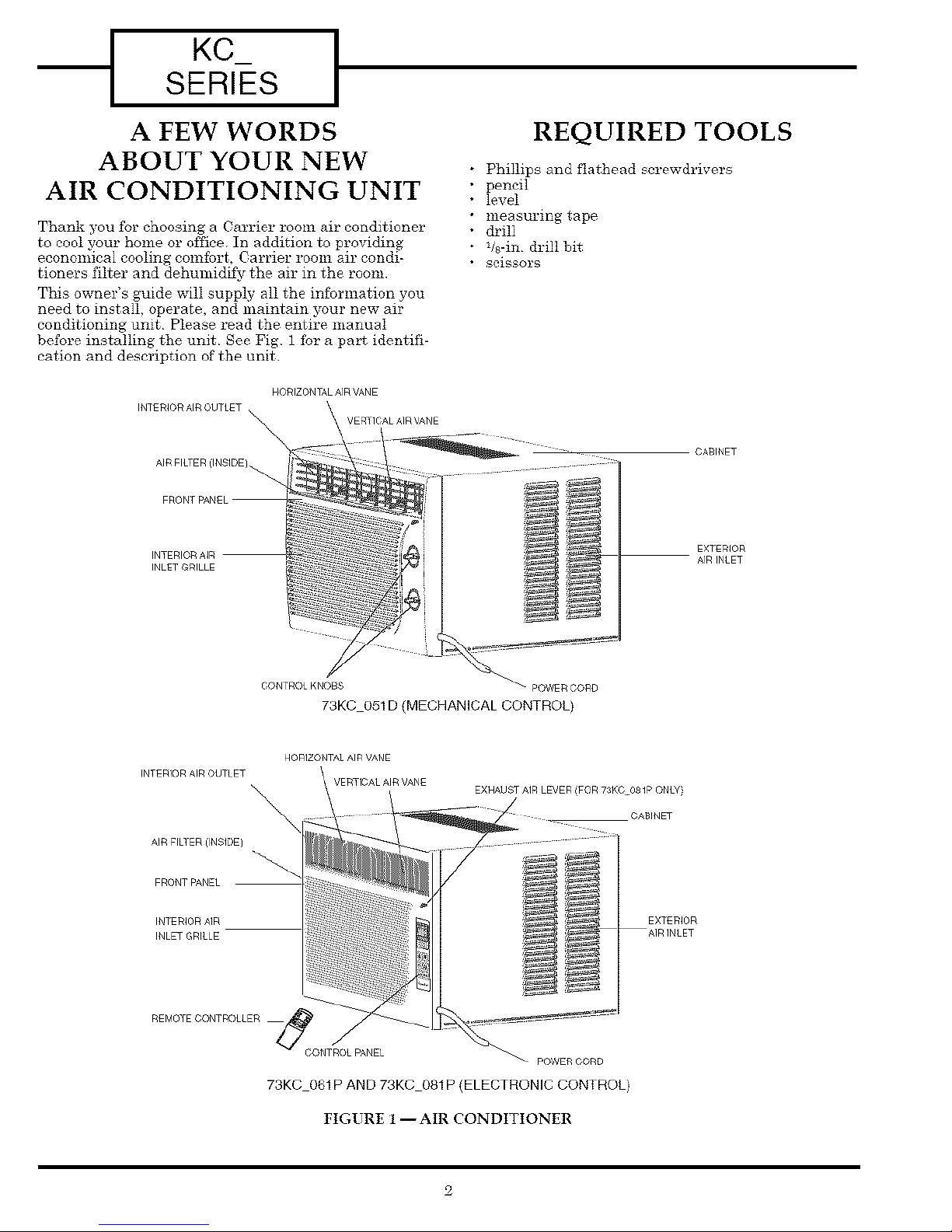
conditioning unit Please read the entire manual
before installing the unit See Fig 1 fbr a part identifi-
cation and description of the unit
HORIZONTAL AIR VANE
INTERIOR AIR OUTLET ,
INTERIOI9 AIR
INLET GRILLE
REQUIRED TOOLS
Phillips and flathead screwdrivers
pencil
level
measuring tape
drill
qs-in drill bit
scissors
CABINET
EX]ERIOR
AIRINtET
INTERIOR AIR OUTLET
AIR FILTER ilNSIDE]
FRONT PANEL
IN] ERIOR AIR
INLET GRILLE
CONTROL KNOBS _ powi F_CORD
73KC 051D (MECHANICAL CONTROL}
HORIZONTAL AIR VANE
VERTICAL AIR VANE
CONTROL PANEL _
73KC 061P AND 73KC 081P (ELECTRONIC CONTROL}
EXHAUST AIR LEVER (FOR 73KC O_1P ONLY}
POWER CORD
FIGURE 1 --AIR CONDITIONER
CABINET
EX]ERIOR
INSTALLATION
Your Carrier room air conditioner was designed to be
installed in a single or double hung window. This air
conditioner is not designed for use with vertical (slider
type) windows
EXCESSIVE %%EIGHT HAZARD
Use two or more people to move and in_talI air
conditioner
any questions regarding the unit electrical data or wir-
ing, consult a qualified electrician before installation
For your safety, this air conditioner is grounded
through the power cord plug when plugged into a
matching wall outlet The power cord is 60dn long.
TABLE 1 -- RECEPTACLE TYPE AND FUSES
RECEPTACLE TYPE AND FUSES
VOLTS INDICATED/Hz 125/60
AMPS 15
WALL OUTLET
UNPACK THE AIR CONDITIONER
Handle air conditioner with care
Remove and properly dispose ofpackaging materials
Remove tape and glue residue from surfaces before
turning on the air conditioner Rub a small amount of
liquid dish soap over the adhesive with your fingers
Wipe with warm water and &T thoroughly
Do not use sharp instruments, rubbing alcohol, flam-
mable fluids or abrasive cleaners to remove tape or
glue These products can damage the surface of your
air conditioner
Electrical shock can cause injur) or death Do not
install unit or remove fl'ont grille with the power
cord plugged in Be sure unit is unplugged befm'e
WIRING
Plug power supply cord intoa grounded 3-prong
outlet Do not remove ground prong Do not use
an adapter Do not use an extension cord
Failure tofollox_these instructionscan resultin
death, fire,or electrical_shock
The airconditioner is powered by plugging itinto a
compatible wall outlet The electricaloutletMUST
match the plug on the unit power cord See Table I for
receptacletypes and fuses The unit nameplate con-
tains unit electricaldata, unit ratings,and identifica-
tion numbers. The unit nameplate is located on the
right side ofthe unit.Do not use a plug adapter or an
extension cord The use of a time-delay fuse or time-
delay circuitbreaker is recommended
Check availablepower supply and resolve an}-wiring
problems before installingand operating the air condi-
tioner Ifwiring isrequired, allwiring must comply
with alllocaland national electricalcodes All wiring
must be installedby a qualifiedelectricianIfyou have
FUSESIZE 15
TIME DELAY FUSE
/_tt'irouitBreaker) Plug Type
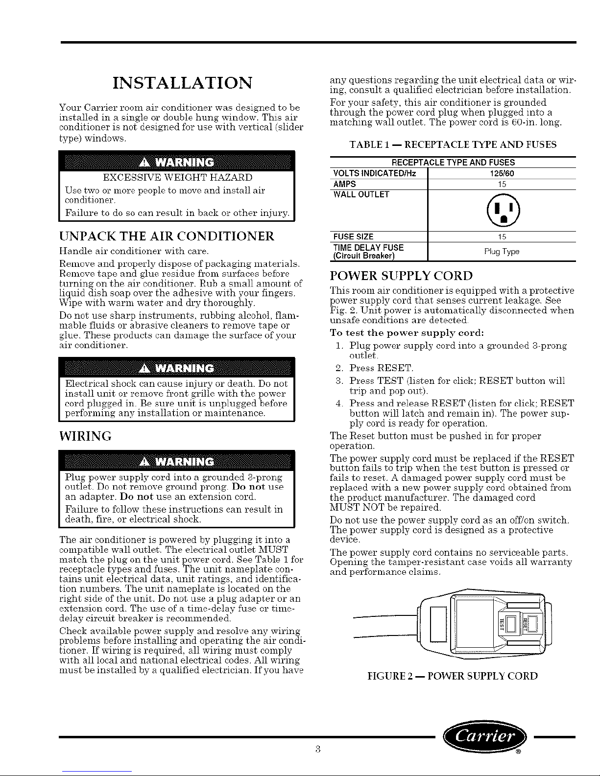
POWER SUPPLY CORD
This room air conditioner is equipped with a protective
power supply cord that senses current leakage See
Fig 2 Unit power is automatically disconnected when
unsafe conditions are detected
To test the power supply cord:
1 Plug power supply cord into a grounded 3-prong
outlet
2 Press RESET
3 Press TEST (listen for click: RESET button will
trip and pop out)
4 Press and release RESET (listen for click: RESET
button will latch and remain in) The power sup-
ply cord is ready Ibr operation
The Reset button must be pushed in for proper
operation
The power supply cord must be replaced if the RESET
button fails to trip when the test button is pressed or
fails to reset A damaged power supply cord must be
replaced with a new power supply cord obtained from
the product manufacturer The damaged cord
MUST NOT be repaired
Do not use the power supply cord as an off/on switch
The power supply cord is designed as a protective
device
The power supply cord contains no serviceable parts
Opening the tamper-resistant case voids all warranty
and perfbrmance claims
FIGURE 2 -- POWER SUPPLY CORD
KCSERIE[S I
LOCATION
The room air conditioner is designed to fit easily into a
single or double hung window However, since window
designs val_-, it may he necessary to make some modi-
fications for saf_ and proper installation
Make sure the window and frame are structurally
sound and free from dl'y or rotted wood Replace wood
if necessal T or relocate the air conditioner to a differ-
ent window
For maximum efficiency, install the air conditioner on
the side of the house or building that has more shade
than sunlight
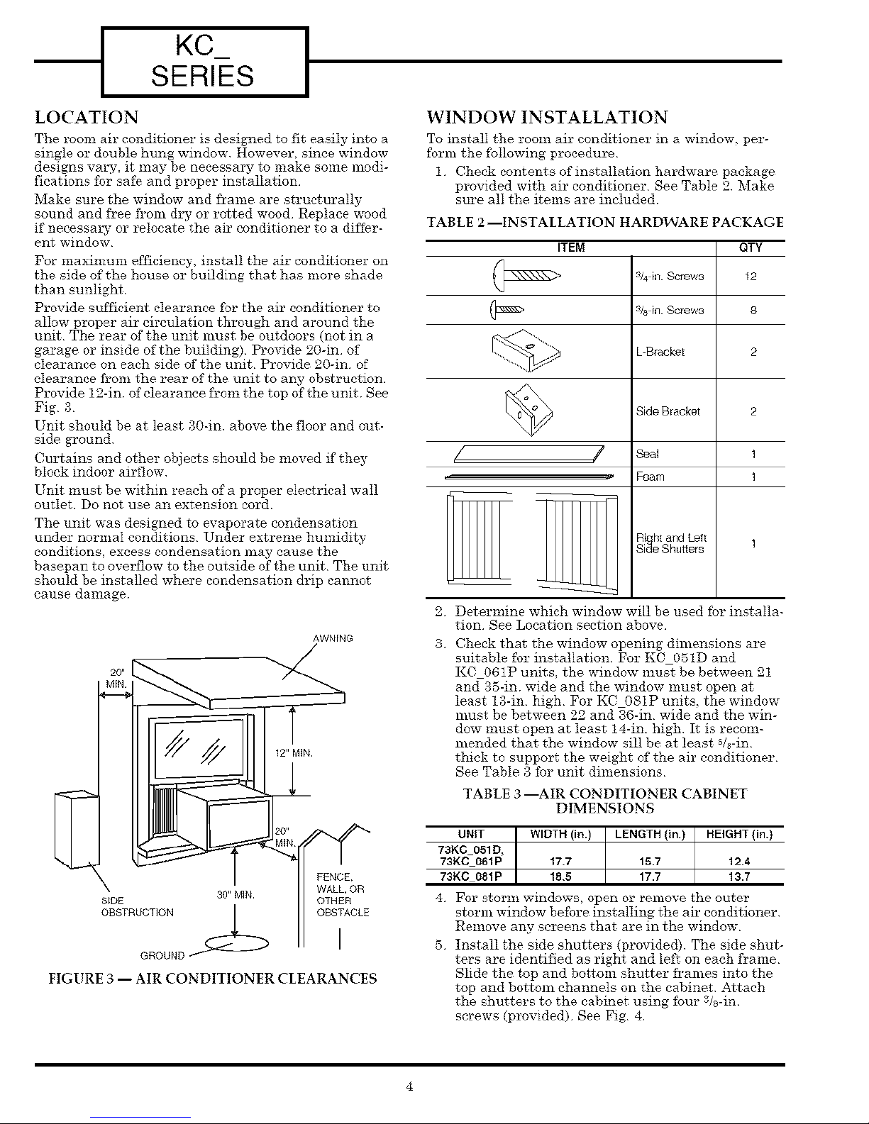
Provide sufficient clearance fbr the air conditioner to
allow proper air circulation through and around the
unit The rear of the unit must be outdoors (not in a
garage or inside of the building) Provide 20-in of
clearance on each side of the unit Provide 20-in of
clearance fi'om the rear of the unit to any obstruction
Provide 12dn of clearance h'om the top of the unit See
Fig g
Unit should be at least g0-in above the floor and out-
side ground
Cullains and other objects should be moved if they
block indoor airflow
Unit must be within reach of a proper electrical wail
outlet Do not use an extension cord
The unit was designed to evaporate condensation
under normal conditions Under extreme humidity
conditions, excess condensation may cause the
basepan to overflow to the outside of the unit The unit
should be installed where condensation drip cannot
cause damage
WINDOW INSTALLATION
To install the room air conditioner in a window, per-
form the fbllowing procedure
1 Check contents of installation hardware package
provided with air conditioner See Table 2 Make
sure all the items are included
TABLE 2 --INSTALLATION HARDWARE PACKAGE
ITEM QTY
s/4h_Screws 12
3/8 [fl Screws 8
L Bracket 2
Side Bracket
/ /
2.
Determine which window will be used for installa-
Seal
Foam
tion See Location section above
3.
Check that the window opening dimensions are
suitable for installation For KC 05ID and
KC 061P units the window must be between 21
and 35-in wide and the window must open at
least I3-in high For KCO81P units, the window
must be between 22 and 36-in wide and the win-
dow must open at least 14-in. high It is recom-
mended that the window sill be at least s/8-in
thick to support the weight of the air conditioner
See Table 3 for unit dimensions
TABLE 3 --AIR CONDITIONER CABINET
DIMENSIONS
2
S_DE
OBSTRUCTION
GROUND
30" MIN
FIGURE 3 -- AIR CONDITIONER CLEARANCES
FENCE
WALL, OR
OTH£R
OBSTACLE
UNIT WIDTH (in.) LENGTH (in) HEIGHT (in.)
73K0 051D,
73KC 061P 17.7 15.7 12.4
73KC 081P 18.5 17.7 13.7
4 For stor]_l windows, open Or re_lo%-e the outer
storm window before installingthe airconditioner
Remove any screens that are in the window
5 Installthe side shutters (provided) The side shut-
ters are identified as right and left on each frame
Slide the top and bottom shutter fi'ames into the
top and bottom channels on the cabinet .Attach
the shutters to the cabinet using fbur s/s-in
screws (provided) See Fig 4
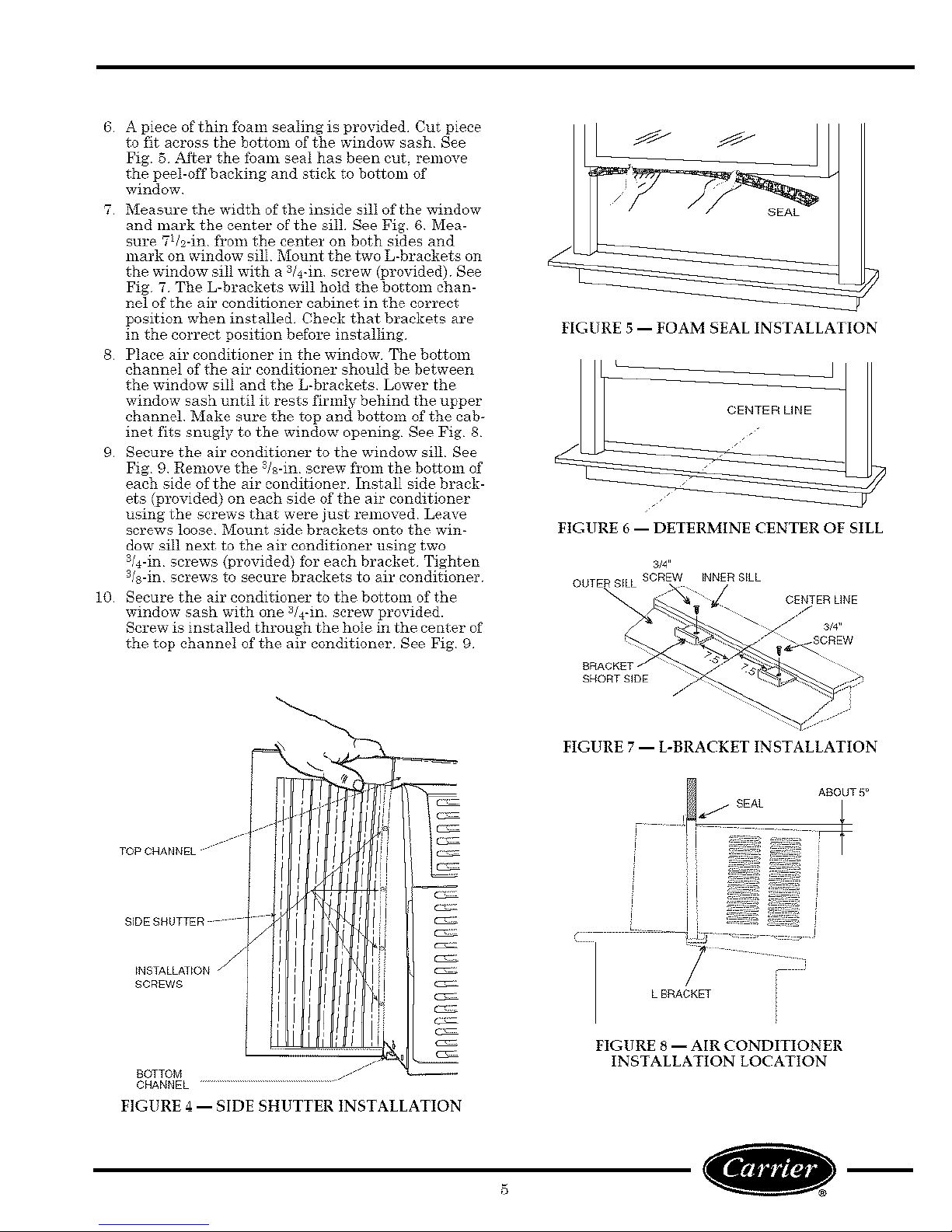
6 ApieceofthinfbamsealingisprovidedCutpiece
tofit acrossthebottomofthewindowsashSee
Fig.5 ._fterthefoamsealhasbeencut,remove
thepeel-offbackingandstickto bottomof
window
7 MeasurethewidthoftheinsidesilIofthewindow
andmarkthecenterofthesill SeeFig 6 Mea-
sure7Us-infi'omthecenteron both sides and
mark on window sill Mount the two L-brackets on
the window sill with a 3/4-m screw (provided) See
Fig 7 The L-brackets will hold the bottom chan-
nel of the air conditioner cabinet in the correct
position when installed Check that brackets are
in the correct position before installing
8 Place air conditioner in the window The bottom
channel of the air conditioner should be between
the window sill and the L-brackets Lower the
window sash until it rests firmly behind the upper
channel Make sure the top and bottom of the cab-
inet fits snugly to the window opening See Pig 8
9 Secure the air conditioner to the window sill See
Fig 9 Remove the s/s-in screw fi'om the bottom of
each side of the air conditioner Install side brack-
ets (provided) on each side of the air conditioner
using the screws that were just removed Leave
screws loose Mount side brackets onto the win-
dow sill next to the air conditioner using two
3/4-in screws (pl"ovided) fbr each bracket Tighten
s/s-in screws to secure brackets to air conditioner
10 Secure the air conditioner to the bottom of the
window sash with one 3/4-in sc_'ew provided.
Screw is installed through the hole in the center of
the top channel of the air conditioner See Fig 9
FIGURE 5 -- FOAM SEAL INSTALLATION
FIGURE 6 -- DETERMINE CENTER OF SILL
BRACKET /
SHORT SIDE
CHANNEL
FIGURE 4 -- SIDE SHUTTER INSTALLATION
FIGURE 7 -- L-BRACKET INSTALLATION
FIGURE 8 -- AIR CONDITIONER
INSTALLATION LOCATION
KCSERIES I
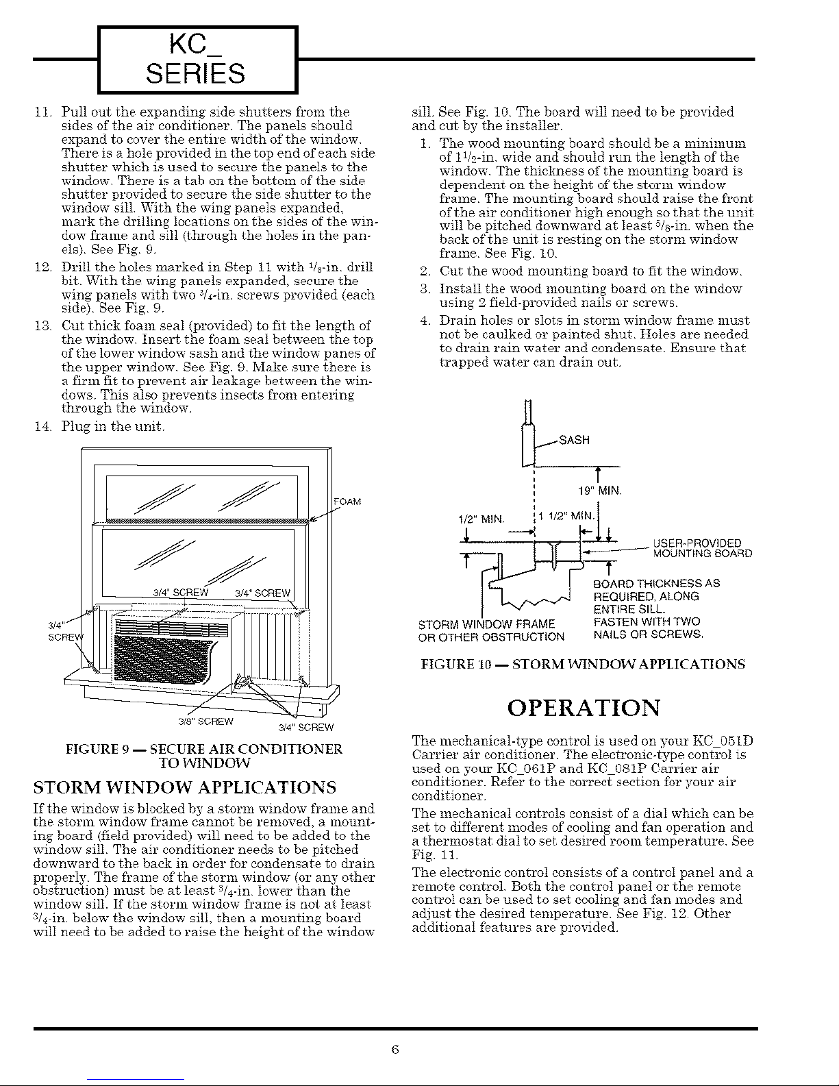
11 Pull out the expanding side shutters from the
sides of the air conditioner The panels should
expand to cover the entire width of the window
There is a hole pro_dded in the top end of each side
shutter which is used to seem'e the panels to the
window There is a tab on the bottom of the side
shutter provided to secure the side shutter to the
window sill With the wing panels expanded.
mark the drilling locations on the sides of the win-
dow frame and sill (through the holes in the pan-
els) See Fig 9
12 Drill the holes marked in Step it with 1&-in drill
bit With the wing panels expande& secure the
wing panels with two _&-in screws provided (each
sido) See Fig 9
13 Cut thick fbam seal (pro%tided) to fit the length of
the window Insert the foam seal between the top
of the lower window sash and the window panes of
the upper window See Fig 9 Make sure there is
a firm fit to prevent air leakage between the win-
dows This also prevents insects fi'om entering
through the window
14 Plug in the unit
sill See Fig. 10 The board will need to be provided
and cut by the installer
1 The wood mounting board should be a minmmm
of 1W-in wide and should run the length of the
window The thickness of the mounting board is
dependent on the height of the storm window
fi'ame The mounting board should raise the fi'ont
of the air conditioner high enough so that the unit
will be pitched downward at least s&-in when the
back of the unit is resting on the storm window
fi'ame See Fig l0
2 Cut the wood mounting board to fit the window
3 Install the wood mounting board on the window
using 2 field-provided nails or screws
4 Drain holes or slots in storm window fi'ame must
not be caulked or painted shut Holes are needed
to drain rain water and condensate Ensure that
trapped water can drain out
19" MIN
3_"SCREW
3_"SCREW
FIGURE 9 -- SECURE AIR CONDITIONER
TO WINDOW
STORM WINDOW APPLICATIONS
If the window is blocked by a storm window frame and
the storm window fi'ame cannot be removed, a mount-
ing board (field provided) will need to be added to the
window sill The air conditioner needs to be pitched
downward to the back in order for condensate to drain
properly The fi'ame of the storm window (or any other
obstruction) must be at least 3/4-in lower than the
window sill. If the storm window frame is not at least
3&-in below the window sill, then a mounting board
will need to be added to raise the height of the window
1/2_MIN 1/2" MIN t
1
!/ USER-PROVIDED----_l
T_I__ MOUNTING BOARD
BOARD THICKNESS AS
STORM WINDOW FRAME FASTEN WITH TWO
OR OTHER OBSTRUCTION NAILS OR SCREWS
FIGURE 10 -- STORM I_'INDOW APPLICATIONS
OPERATION
The mechanical-type control is used on your KC05ID
Carrier air conditioner The eleetronie-tppe control is
used on your KCO61P and KC 081P Carrier air
conditioner. Refer to the correctsection fbr your air
conditioner
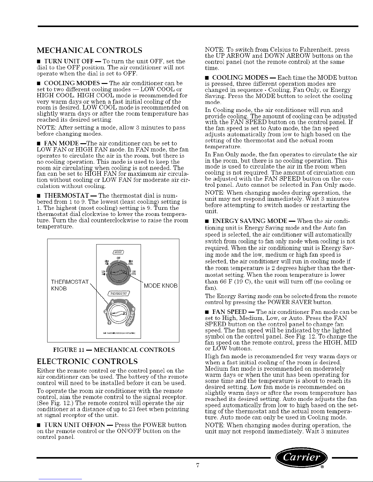
The mechanieaI controls consist of a dial which can be
sot to different modes of cooling and fan operation and
a thermostat dial to set desired room temperature See
Fig ii
The electronic control consists of a eontroI panel and a
remote control Both the control panel or the remote
control can be used to set cooling and fan modes and
adjust the desired temperature See Fig 12 Other
additional f_atures are provided
MECHANICAL CONTROLS
• TURN UNIT OFF -- To turn the unit OFF, set the
dial to the OFF position The air conditioner will not
operate when the dial is set to OFF
• COOLING MODES -- The air conditioner can be
set to two different cooling modes LOW COOL or
HIGH COOL HIGH COOL mode is recommended fbr
vel T warm days or when a fast initial cooling of the
room is desired LOW COOL mode is recommended on
slightly warm days or after the room temperature has
reached its desired setting
NOTE: .adter setting a mode, allow 3 minutes to pass
before changing modes
• FAN MODE --The air conditioner can be set to
LOW FAN or HIDH FAN mode In FAN mode, the fan
operates to circulate the air in the room, but there is
no cooling operation This mode is used to keep the
room air circulating when cooling is not needed The
fan can be set to HIGH FAN for maxmmm air circula-
tion without cooling or LOW FAN for moderate air cir-
culation without cooling
• THERMOSTAT -- The thermostat dial is num-
bered from 1 to 9 The lowest (least cooling) setting is
1 The highest (most cooling) setting is 9 Turn the
thermostat dial clockwise to lower the room tempera-
ture Turn the dial counterclockwise to raise the room
tenlperature
THERMOSTAT
KNOB
MODE KNOB
FIGURE 11 -- MECHANICAL CONTROLS
ELECTRONIC CONTROLS
Either the remote control or the control panel on the
air conditioner can be used The batter>" of the remote
control will need to be installed before it can be used
To operate the room air conditioner with the remote
control, aim the remote control to the signal receptor
(See Fig 12) The remote control will operate the air
conditioner at a distance of up to 2;3 feet when pointing
at signal receptor of the unit
• TURN UNIT OFF/ON -- Press the POWER button
on the remote control or the ON/OFF button on the
control panel
NOTE: To switch from Celsius to Fahrenheit, press
the UP ARROW and DOWN ARROW buttons on the
control panel (not the remote control) at the same
time
• COOLING MODES -- Each tilne the MODE button
is pressed, three different operation modes are
changed in sequence - Cooling, Fan Only, or Energy
Saving. Press the MODE button to seleet the eooting
mode
In Cooling mode, the air conditioner will run and
provide cooling The amount of cooling can be adjusted
with the FAN SPEED button on the eontrol panel If
the fan speed is set to Auto mode, the fan speed
adjusts automatically from low to high based on the
setting of tlae thermostat and the actual room
temperature
In Fan Only mode, the fan operates to circulate the air
in the romn, but there is no cooling operation This
mode is used to circulate the air in the room when
cooling is not required The amount of eirculation can
be adjusted with the F_axNSPEED button on the con-
trol panel Auto cannot be selected in Fan Only mode
NOTE: When changing modes during operation, the
unit may not respond immediately Wait g minutes
before attempting to switch modes or restarting the
unit
• ENERGY SAVING MODE -- VV_nenthe air condi-
tioning unit is Energy Saving mode and the Auto fan
peed is selected, the air conditioner will automatically
switch fl'om cooling to fan only mode when cooling is not
required _X_nenthe air conditioning unit is Energy Sav-
ing mode and the low. medimn or high fan speed is
elected, the air conditioner will run in cooling mode if
the room temperature is 2 degrees higher than the ther-
mostat setting When the room temperature is lower
than 66 F (19 C), the unit will turn off (no cooling or
fan)
The Energy Sa_lng nmde can be selected from the remote
control by pressing the POWER SAVER button
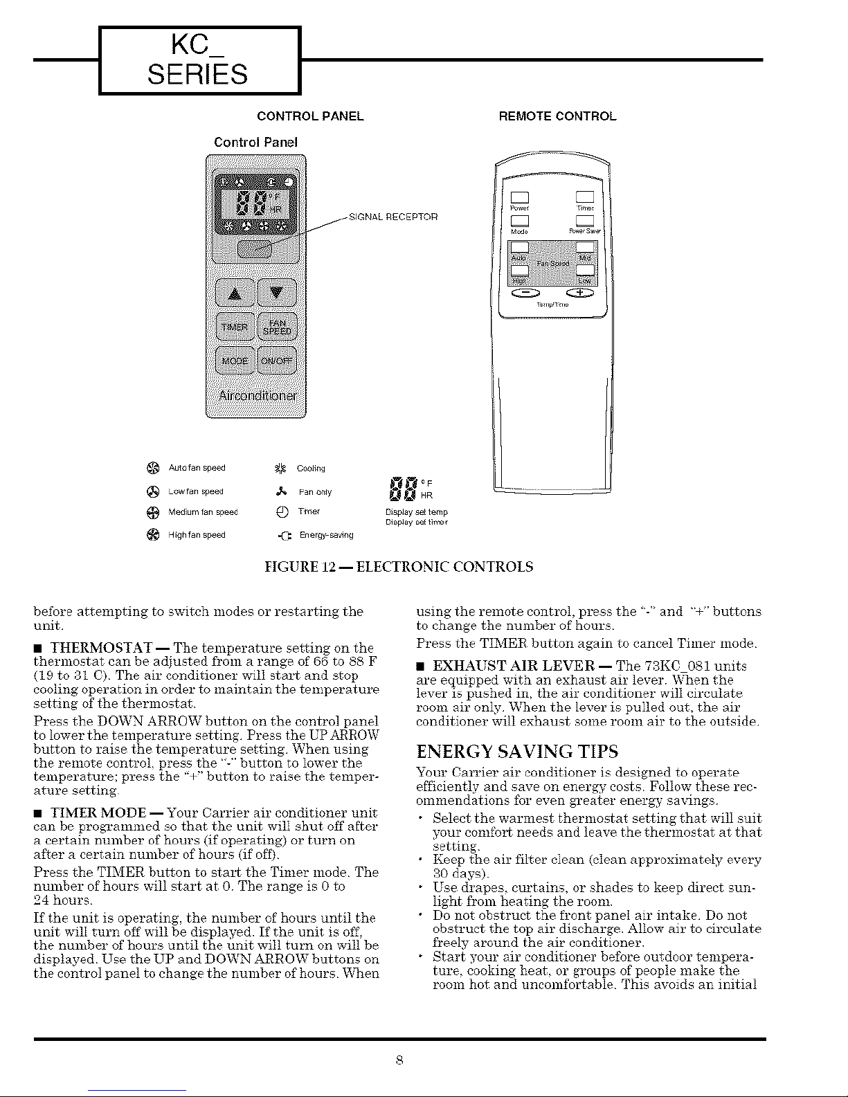
• FAN SPEED -- The air conditioner Fan mode can be
set to High. Medium, Low, or Auto Press the F.%N
SPEED button on the control panel to change fan
speed The fan speed will be indicated by the lighted
symbol on the control panel See Fig 12 To change the
fan speed on the remote control, press the HIGH. MID
or LOW buttons.
High fan mode is recommended fbr very warm days or
when a fast initial cooling of the room is desired
Medium fan mode is reeommended on moderately
warm days or when the unit has been operating for
some time and the temperature is about to reach its
desired setting Low fan mode is recommended on
slightly warm days or after the room temperature has
reached its desired setting Auto mode adjusts the fan
speed automatically from low to high based on the set-
ting of the thermostat and the actual room tempera-
ture Auto mode can only be used in Cooling mode.
NOTE: When changing modes during operation, the
unit may not respond immediately Wait 3 minutes
KCSERIES I
AUI_ f_n speed
(_ LOW f_n speed
Medium f_n sp_d
High f_n speed
CONTROL PANEL
Control Panel
REMOTECONTROL
_ SIGNAL RECEPTOR
FIGURE 12 -- ELECTRONIC CONTROLS
before attempting to switch modes or restartingthe
unit
• THERMOSTAT -- The temperature setting on the
thermostat can be adjusted h'om a range of 66 to 88 F
(19 to 31 C) The air conditioner will stax_ and stop
cooling operation in order to maintain the temperature
setting of the thermostat
Press the DOWN ARROW button on the control panel
to lower the temperature setting Press the UP ARROW
button to raise the temperature setting When using
the remote control, press the "-" button to lower the
temperature; press the "+" button to raise the temper-
ature setting
• TIMER MODE--Your Carrier air conditioner unit
can be programmed so that the unit will shut off after
a certain nmnber of hours (if operating) or turn on
after a certain number of hours (if off)
Press the TIMER button to stax_ the Timer mode The
number of hours will start at 0 The range is 0 to
24 hours
If the unit is operating, the number of hours until the
unit will turn off will be displayed If the unit is off.
the number of hours until the unit will turn on will be
displayed Use the UP and DOWN ARROW buttons on
the control panel to change the number of hours _%_en
using the remote control,press the "-' and "+" buttons
to change the number of hours
Press the TIMEIR button again to cancel Timer mode
• EXHAUST AIR LEVER--The 73K0 081 units
are equipped with an exhaust air lever _nen the
lever is pushed in, the air conditioner will circulate
room air only When the lever is pulled out, the air
conditioner will exhaust some room air to the outside
ENERGY SAVING TIPS
Your Carrier air conditioner isdesigned to operate
efficientlyand save on energy costs Follow-these rec-
ommendations foreven greater energy sa_dngs
Selectthe warmest thermostat settingthat willsuit
your comfot_ needs and leave the thermostat at that
setting
Keep the air filter clean (clean approximately every
30 days).
Use drapes, curtains,or shades to keep directsun-
lightfrom heating the room
Do not obstruct the front panel airintake Do not
obstruct the top air discharge Allow airto circulate
freelyaround the airconditioner
Start your air conditioner before outdoor tempera-
ture,cooking heat, or groups ofpeople make the
room hot and uncomfortable This avoids an initial
period of discomfort while the air conditioner is cool-
ing the room
• When outdoor temperature is cool enough, use the
Fan Only setting This circulates indoor air, pro-
vides eomfbrt, and utilizes less electricity than
when operating in cooling modes
MAINTENANCE
When servicing the air conditioner, make sure the
mode is set to OFF and the unit is unplugged fl'om the
electrical outlet
CLEAN FILTER
Normally, the air filter should be cleaned every
_30 days. The filter is highly efficient in removing
airborne particles More frequent cleaning may be
required in areas with low outdoor and indoor air
quality
To remove the filter, grasp the filter handle tabs on
the top center of the fl'ont inlet grille and slide the fil-
ter out to the top. The filter may be vacuumed or
washed by hand in warm water Use of a mild deter-
gent is recommended Dry the filter thoroughly after
washing Replace the air fiher by sliding it back into
the filter slot Do not operate the unit without the
filter
Do not spill liquids or place heavy objects on the
remote control Make sure the signal fl'om the remote
eontroI to the air conditioner is unobstructed
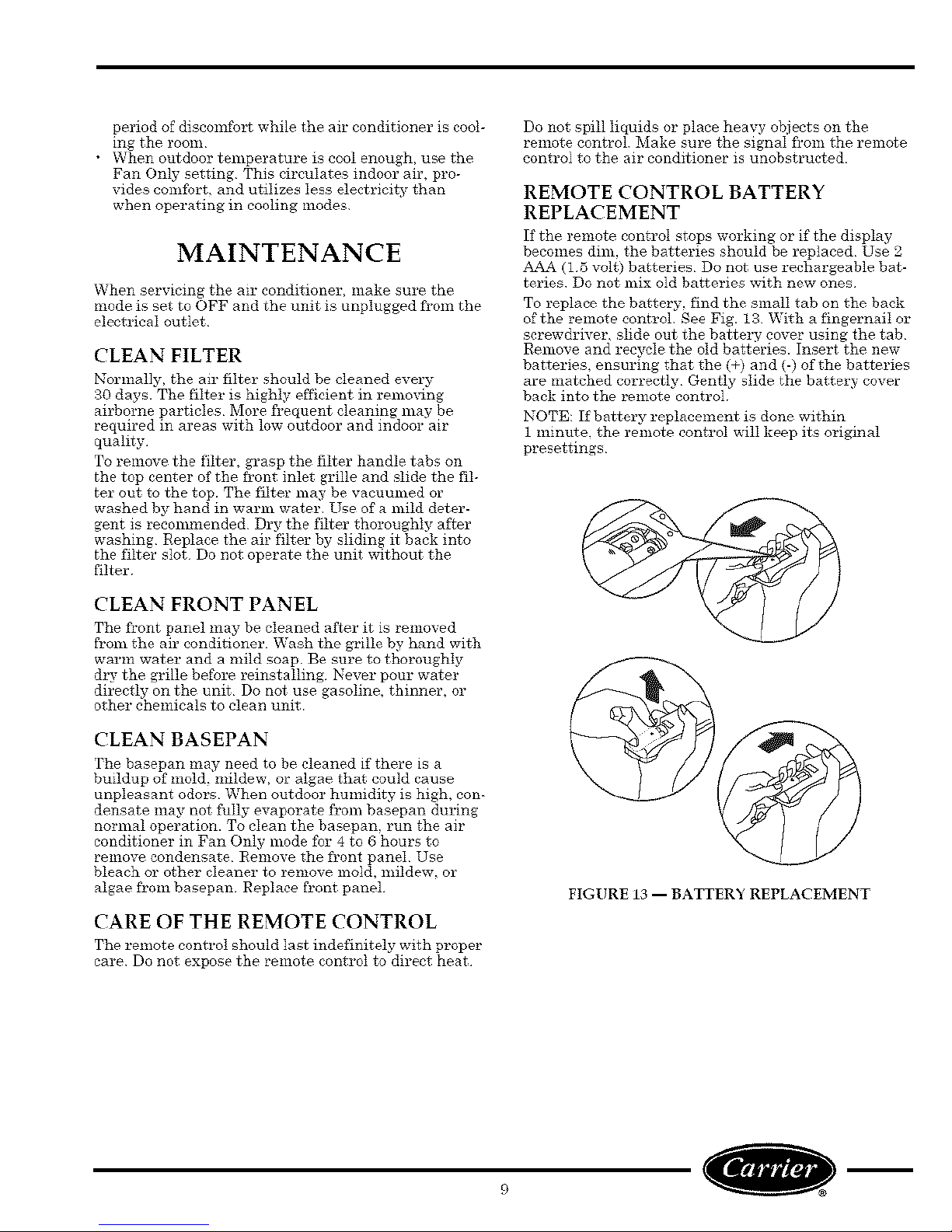
REMOTE CONTROL BATTERY
REPLACEMENT
If the remote eontroI stops working or if the display
becomes dim, the batteries should be replaeed Use 2
AAA (15 volt) batteries Do not use rechargeable bat-
teries Do not mix old batteries with new ones
To replace the battery, find the small tab on the back
of the remote control See Fig. 18 With a fingernail or
screwdriver, slide out the battelT cover using the tab
Remove and rees_Ie the old batteries. Insert the new
batteries, ensuring that the (+) and (-) of the batteries
are matched correctly Gently slide the battery cover
back into the remote control
NOTE: If battery replacement is done within
1 minute, the remote control will keep its original
presettings
CLEAN FRONT PANEL
The fgont panel may be cleaned after it is removed
from the air conditioner. Wash the grille by hand with
warm water and a mild soap Be sure to thoroughly
&T the grille before reinstalling Never pour water
directly on the unit Do not use gasoline, thinner, or
other chemicals to clean unit
CLEAN BASEPAN
The basepan may need to be cleaned if there is a
buildup of mold, mildew, or algae that could cause
unpleasant odors When outdoor humidity is high, con-
densate may not fully evaporate fl'om basepan during
normal operation. To clean the basepan, run the air
conditioner in Fan Only mode for 4 to 6 hours to
remove condensate Remove the fl'ont panel Use
bleach or other cleaner to remove mold, mildew, or
algae from basepan Replace fl'ont panel
CARE OF THE REMOTE CONTROL
The remote control should last indefinitely with proper
care Do not expose the remote eontrot to direct heat
FIGURE 13 -- BATTERY REPLACEMENT
-I KCSERIES I
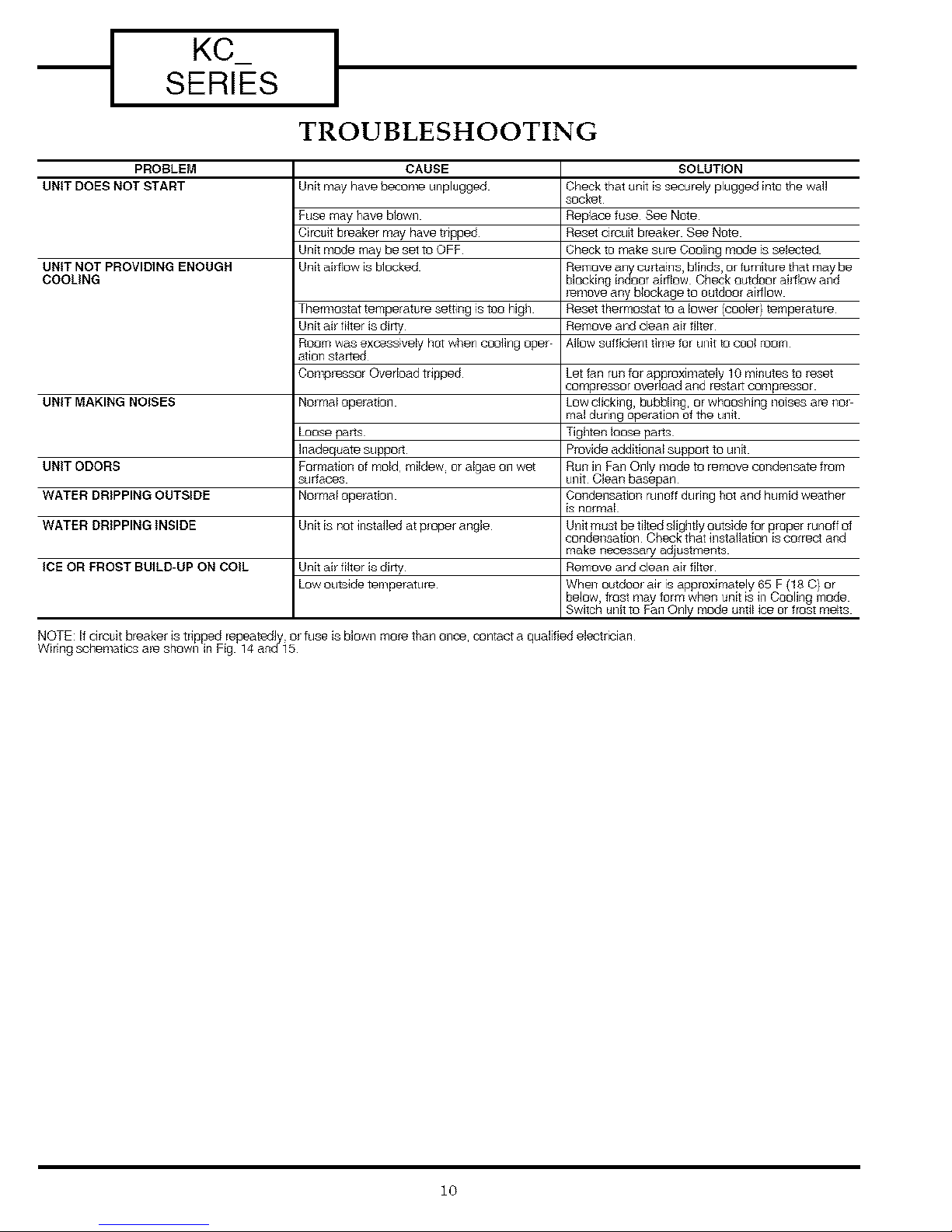
TROUBLESHOOTING
PROBLEM
UNIT DOES NOT START
UNIT NOT PROVIDING ENOUGH
COOLING
UNIT MAKING NOISES
UNIT ODORS
WATER DRIPPINGOUTSIDE
Unit may have _ome unplugged
Fuse may have bIQwlq
Circuit bpeaker may have tripped
Unit mode may be set to OFF
Unit airflow is blocked
Thermostat temperature setting is ton high
Unit air filter is dirty
Roam was excessively hot when cooling oper
orion started
Compressor Overloed tripped
No_real opelation
hQose p_crtS
Inadequate support
Formation of mold mildew or algae on wet
surfaces
No_real ope_ation
CAUSE
SOLUTION
Check tPat unit is securely plugged into the wall
socket
Replace fuse See Note
Reset ckcuit breaker See Note
Check to make sure Coaling mode E,selected
_move any blockage to outdoor aidlow
Reset thermostat to a lower (cooler) t_mperature
Remove and dean air filter
Allow sufficient time for unit to coo_ room
Tighten loose parts
Provide additional suppnrt to unit
Run in Fan Only mede to remove condensate from
unit Clean basepan
Condens_ion runoff during hot and humid weather
is normal
WATER DRIPPING INSIDE Unit is not installed atp_oparangle
make necessary a_ustments
ICEOR FROST BUILD-UP ON COIL Remove and clean air filter
Unit airfilter is dirty
Lawout.ide tumperatuie
10
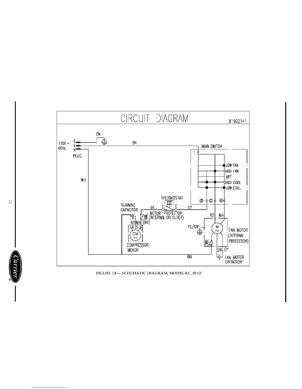
115VN _k_60Hz
PLUG
WH
CIRCUITDIAGRAM 81902141
GN
BR
THERMOSTAT
RUNNING BK
OTORPROTECTOR
ALOROUTER)
AIN SWITCH
LOWFAN
HIGHFAN
OFF
HIGHCOOL
LOWCOOL
GY
RD
YE/GN FANMOTOR
INTERNAL
COMPRESSOR
MOTOR
BU
GY
FAN MOTOR
CAPACITOR
FIGURE 14--SCtlEMATIC DIAGRAM; MODELKC 051D
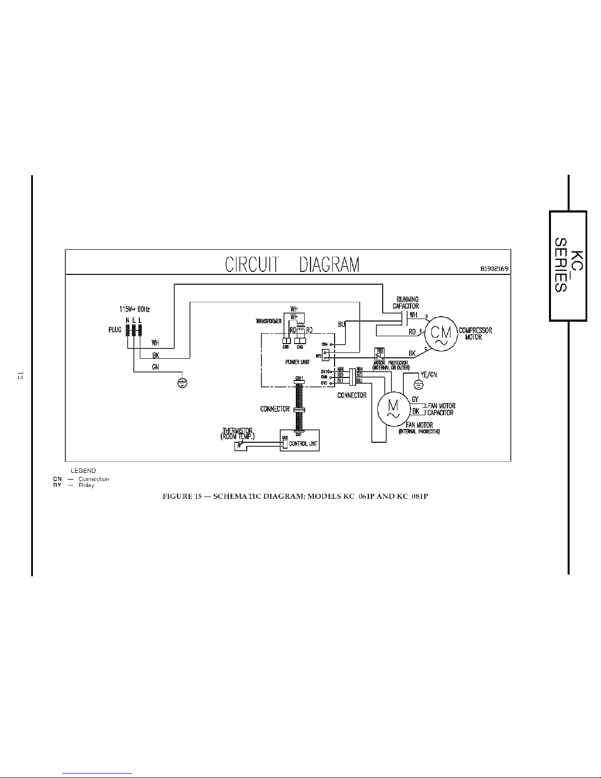
CIRCUITDIAGRAM o,9o2,o9
NEL
RUNNING
CAPACITOR
RD COMPRES_OR
MOTOR
_/GN
CONNECTOR
CONNECTOR
LNMOTOR
GO
mpK
___o
ml
GO
LEGEND
CN -- Conne_n
RY -- Rely
FIGUREI5--SCHEMATICDIAGRAM;MODELSKC 0(,]PANDKC 081P

Carrier Room Air Conditioner Full Warranty
ONE YEAR WARRANTY CARRIER warrants to the user that this produd will be free f{om delect'4 5f workmanship under normal
use and maintenance for a beodd of one year from the date of original pul_hase CARRIER, through its authorized independent servic
ing bea_rs or service stations¸ will either repair or replace a d_ec@e product (as decided salely by CARRIER) free of charge to the
user _CARRIER may replace any d_ec_ive part with either a new o_ren/andactured pan at CARRfER's sole option
EXTENDED FOUR YEAR WARRANTY ON SEALED REFRfGERAT{ON SYSTEM ONLY During the second through fifth years
_er date of original pu_hase CARRIER f_rtber warrants ta the user that the compressor condenser¸ evaporator, and connecting
tubing wilJ be flee from de_cts in material or workmanship under normal use and maintenance CARRIER will either repair or replace
(as decided seMy by CARRIER) acy defective compressor¸ conbenser evaporator or connecting tubing lree of cha_ge to the user
including a recharge of refrigerant for the system if necessary Hewever, THIS LIMITED WARRANTY DOES NOT iNCLUDE costs
incurred for di_nosing, removi% installing¸ shipping t3rtransporting the product or any parts User is resbensibb for these costs;
bewev_r SUCH COSTS MAY BE COVERED by a separa_ warranty o_ serwce agreement p_ovibed by the se{ler o_ another thi_
party¸ such agreement being separate and di_inct from this factory warranty
LIMiTATiON OF WARRANTIES ALL IMPUED WARRANTIES (iNCLUDiNG IMPUED WARRANTIES OF MERCHANTABILITY
AND FITNESS FOR A PARTICULAR PURPOSE) ARE HEREBY LIMITED iN DURATION TO THE PERIOD FOR WHICH THE
APPLICABLE PRODUCT COMPONENT iS EXPRESSLY WARRANTED HEREIN Some _ates o_ provinces do not allow limitations
8n how Jongan implied warranty lasts¸ so the above limitation may not apply to you THE EXPRESS WARRANTIES MADE IN THiS
WARRANTY ARE EXCLUSIVE AND MAY NOT BE ALTERED¸ ENLARGED OR CHANGED BY ANY DISTRIBUTOR, DEALER¸ OR
OTHER PERSON WHATSOEVER CARRIER WILL NOT BE RESPONSIBLE FOR ANY SPECIAL, INCIDENTAL OR CONSEQUEN
TIAL PROPERTY OR COMMERCIAL DAMAGES OF ANY NATURE WHATSOEVER Some states or provinces do not allow tbe
exclusion of inciden_l or consequential damages, so the above limitation may not apply to you AIJwork prov_ed for by this warranty
sbell be performed du_thg no_mal working hours All replacement pa_ whether new o_ remanulactured, assuiTe as their warran_
period onJy the remaining time befiod for wh_h the applicable component is expre_ly warranted herein
_Authorrzed sndep_ndent dealers ol serwce s_tlon_ are reg_tered w#h CARRIER _l_ugh itsdlstnbutol ol_anszatlon
CARRIER WILL NOT BE RESPONSIBLE FOR:
1 Damage due to fdB_ to perform normal mainterance outlined in the Owners Guide
2 b_trudion on methods of control and use 5f air conditioning unit alter ir;itial installallon
3 Damageorrepai_sneededasaconsequencedfauJtyinsta]lationo_ application T_gsistherespz_nsibi]ityoftheinstalbr
4 FaiBre tn start due tn voltage con@inr;s blown fuses open circuit bre_kem or any other damages due to the inadequacy o_ inter
_pben of el_-_r_cal se_ice
5 Damage or _ep@s needed as a co_ sequence of acy m_sapplicaben abuse, unautbe_izod alteration _mprorer nervicing or
nperation
6 Damage as a result of flonds, winds fires lightning acddent_ corrosive enwronments or other conditions beyond the control ol
CARRIER
7 Any part_ not supphed or designatod by CARRfER
8 CARR]ERproductsinstdlodouY:idethecontinentalUSA Alaska, Hawaii, andCanada
9 Shipping dam@e or damage as a result 5f stodng or t_anqoorting 1fie unit
This wa_tan[y gives you specific nghts, and you may also have otbet @be, which vary f_om state to state e¢ p_ovince to p_ovince
IF YOUR UNIT DOES NOT WORK, FOLLOW THESE STEPS IN ORDER:
1 Check the things you can do yaumelf These include being sure the air conditioner is plugged in an app{odbete receptacle check
ing the luse o_ cimuit breaker and ensunng its _eplacement or resetting if necessay, and rereading the instruction book to ensure
all controls a_eset p_odedy By doirg this you can save money Many unnecessary calls result in the serv_:eman duing what the
uwner car; do for himself
2 CONTACTYONRDEALERONTHECARRERAUTHORIZEDSERVICECENTER Youmayfindthisnameprintedonthep_od
uct on your w_vnice or in ynur Homeowner's Packet
3 CONTACT THE NEAREST CARRIER DISTRIBUTOR SERVING YOUR AREA (See Tebpbene Yellow Pages )
4 CONTACT CARRfER JFA SATISFACTORY SOLUTION IS NOT REACHED IN STEPS # AND 3
Carrier Air Conditioning Consumer Relations Department P O Box 4808, Carrier P,=rkw,# Syracuse New York 13#21
Te]epbene: 1800 CARRIER From Canada: (315) 43# 7885
FOR FUTURE REFERENCE, FILL IN DETAILS OF YOUR PURCHASE. KEEP YOUR SALES RECEIPT.
Model/Catal% No Inst_lbd By
Service/Discrete No Name nf Owner
Unit Serial No Addtesr, of lnstdBt or;
Date d InstdBben
13
 Loading...