

Carrier KAAFT0101AAA Installation Instructions Manual
KAAFT0101AAA
Installation Instructions
Evaporator Freeze Th ermostat
NOTE: Read the entire instruction manual before starting the
installation.
SAFETY CONSIDERATIONS
Improper installation, adjustment, alteration, service, maintenance,
or use can cause explosion, fire, electrical shock, or other
conditions which may cause death, personal injury, or property
damage. Consult a qualified installer, service agency, or your
distributor or branch for information or assistance. The qualified
installer or agency must use factory- authorized kits or accessories
when modifying this product. Refer to the individual instructions
packaged with the kits or accessories when installing.
Follow all safety codes. Wear safety glasses, protective clothing,
and work gloves. Use quenching cloth for brazing operations.
Have fire extinguisher available. Read these instructions
thoroughly and follow all warnings or cautions included in
literature and attached to the unit.. Consult local building codes
and current editions of the National Electrical Code ( NEC ) NFPA
70. In Canada, refer to current editions of the Canadian electrical
code CSA 22.1.
Recognize safety information. This is the safety- alert symbol
When you see this symbol on the unit and in instructions or
manuals, be alert to the potential for personal injury.
Understand the signal words DANGER, WARNING, and
CAUTION. These words are used with the safety- alert symbol.
DANGER identifies the most serious hazards which will result in
severe personal injury or death. WARNING signifies hazards
which could result in personal injury or death. CAUTION is used
to identify unsafe practices which may result in minor personal
injury or product and property damage. NOTE is used to highlight
suggestions which will result in enhanced installation, reliability, or
operation.
INTRODUCTION
These instructions cover the installation of the Evaporator Freeze
Thermostat Part No. KAAFT0101AAA on residential split-system
air conditioners and heat pumps.
DESCRIPTION AND USAGE
This device is designed to prevent damage to the compressor by
shutting down the outdoor section in the event of indoor coil
freeze- up.
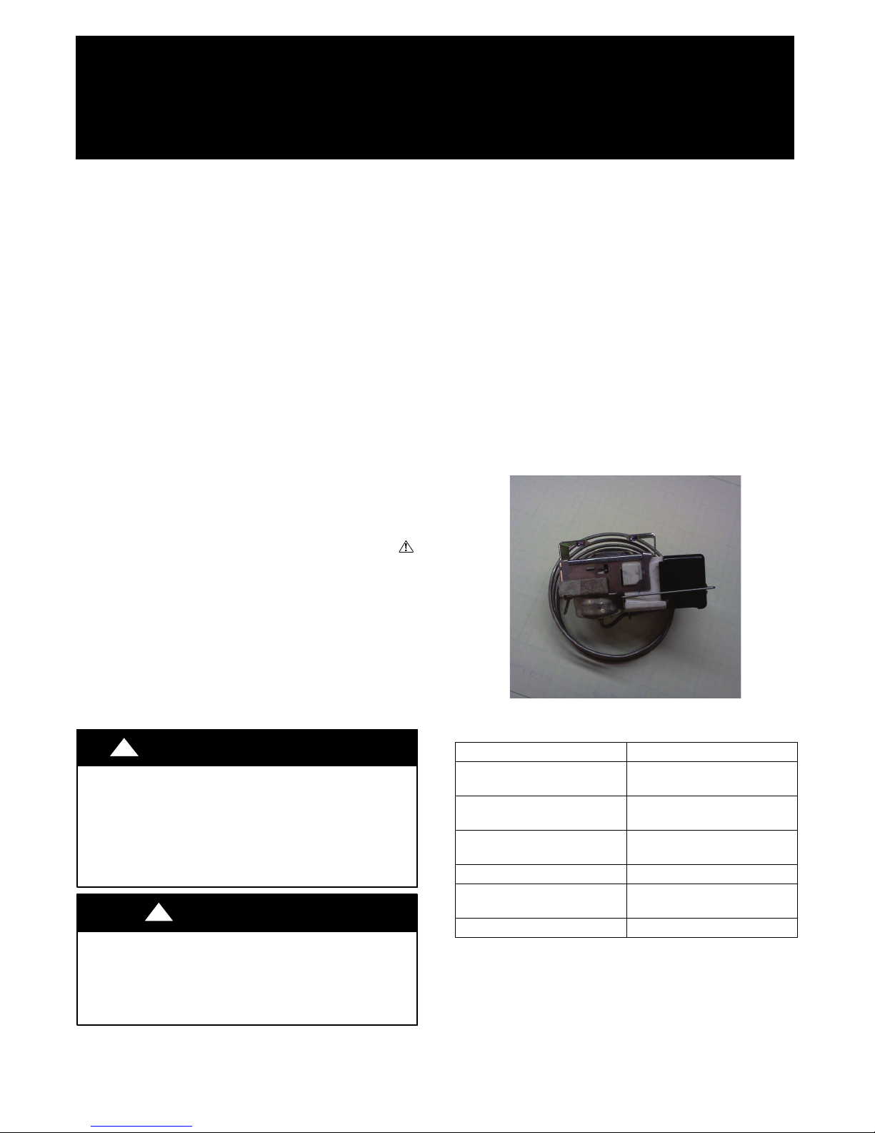
The kit contains the following items:
S Temperature switch (HH22JB026) 1...
S Installation Instructions 1............
.
Additional items required for installation:
!
ELECTRICAL SHOCK HAZARD
Failure to follow this warning could result in personal injury
or death.
Before installing, modifying, or servicing system, main
electrical disconnect switch must be in the OFF position and
install a lockout tag. There may be more than 1 disconnect
switch. Lock out and tag switch with a suitable warning label.
CUT HAZARD
Failure to follow this caution may result in personal injury.
Sheet metal parts may have sharp edges or burrs. Use care and
wear appropriate protective clothing and gloves when
handling parts.
WARNING
!
CAUTION
Description
Standard 4x4, 4-in. electrical
box and cover
No. 8, 32x1/2-in. sheet metal
screws
No. 10, 24x1/2-in. sheet metal
screws
Wire ties 2
16- gage wires (length to be de-
termined by installer)
Insulation (Arm- flex) Enough for bulb coverage
Qty
1
2
2
2

INSTALLATION
PROCEDURE 1 — MOUNT THERMOSTAT
Make sure all power to unit is turned off
!
ELECTRICAL SHOCK HAZARD
Failure to follow this warning could result in personal injury
or death.
Before installing, modifying, or servicing system, main
electrical disconnect switch must be in the OFF position and
install a lockout tag. There may be more than 1 disconnect
switch. Lock out and tag switch with a suitable warning label.
UNIT DAMAGE HAZARD
Failure to follow this caution may result in unit damage.
Exercise extreme caution when drilling holes. Do not puncture
coil and/or tubing.
WARNING
!
CAUTION
1. Remove knockout in bottom of electrical box.
2. Drill two 3/16- inch diameter clearance holes in right- hand
side of electrical box, 1- inch apart. Position holes in side of
box to ensure clearances for mounting of thermostat. (See
Fig. 1.)
3. From within box, pass Evaporator Freeze Thermostat bulb
through knockout hole. Do not mount thermostat to box
at this time.
4. Attach Evaporator Freeze Thermostat bulb to vapor line,
using two wire ties, as close to evaporator coil as possible.
(See Fig. 1.)
5. Position electrical box on side of plenum or coil casing. Be
sure location is NOT near coil surface. Drill two 9/64 or no.
27 holes through holes provided in electrical box into plenum or casing.
6. Mount electrical box to plenum or casing using two No.10,
24x1/2- inch sheet metal screws. (See Fig. 1.)
7. Mount Evaporator Freeze Thermostat to side of electrical
box using two No. 8, 32x1/2- inch sheet metal screws.
8. Route wires for bulb through knockout hole in electrical
box and connect to Evaporator Freeze Thermostat.
9. Wire Evaporator Freeze Thermostat in series with Y
(single- stage) or Y1 (two- stage) low-voltage wire from indoor thermostat at indoor unit, to outdoor unit. (See Fig. 2
through 5.)
10. Secure cover to electrical box.
11. Insulate Evaporator Freeze Thermostat bulb.
TO CONTROL
WIRING
3
⁄
16
-IN.
HOLES
Fig. 1- Mounting Thermostat on Coil Casing
A97510
2
 Loading...