

Page 1

u
ii--VVu
®
®
XXTT RRoouutteerr
IInnssttaallllaattiioonn aanndd SSttaarrtt--uupp GGuuiiddee
CARRIER CORPORATION ©2018
A member of the United Technologies Corporation family · Stock symbol UTX · Catalog No. 11-808-580-01 · 10/2/2018
Page 2

www.hvacpartners.com
Document revision history
Verify that you have the most current version of this document from
or your local Carrier
office.
Important changes are listed in
at the end of this document.
CARRIER CORPORATION ©2018. All rights reserved throughout the world. i-Vu is a registered trademark of Carrier
Corporation. All other trademarks are the property of their respective owners.
Page 3

What is the i-Vu® XT Router? ..................................................................................................................................... 1
To mount the i-Vu® XT Router .................................................................................................................................... 4
Wiring for power .......................................................................................................................................................... 6
Addressing the i-Vu® XT Router ................................................................................................................................. 7
Wiring for communications ...................................................................................................................................... 11
Find and upload in the i-Vu® interface .................................................................................................................... 14
Adjusting the i-Vu® XT Router driver properties ..................................................................................................... 15
To set up the controller through the Service Port ................................................................................................... 25
Troubleshooting ......................................................................................................................................................... 30
Compliance ................................................................................................................................................................ 36
Appendix - Module Status field descriptions ........................................................................................................... 37
Document revision history ........................................................................................................................................ 39
Contents
Specifications ........................................................................................................................................................ 1
To wire for power .................................................................................................................................................. 6
Rotary switch settings .......................................................................................................................................... 7
To set the IP address ............................................................................................................................................ 8
To set the Port S1 address and baud rate ..................................................................................................... 10
To set the Port S2 address and baud rate ..................................................................................................... 10
Wiring specifications ......................................................................................................................................... 11
To connect the i-Vu® XT Router to the Ethernet ........................................................................................... 12
To wire to a BACnet/ARCNET network ........................................................................................................... 13
To wire to a BACnet MS/TP network .............................................................................................................. 13
Driver ................................................................................................................................................................... 15
Device .................................................................................................................................................................. 15
Notification Classes ........................................................................................................................................... 16
Calendars ............................................................................................................................................................ 17
Common and Specific Alarms ......................................................................................................................... 18
BACnet router properties .................................................................................................................................. 18
BACnet firewall ................................................................................................................................................... 18
Network Diagnostics - Statistics ...................................................................................................................... 19
Network Diagnostics - Packet Capture ........................................................................................................... 21
Communication Status ..................................................................................................................................... 23
To set up Network Statistic trends .................................................................................................................. 23
ModStat tab ........................................................................................................................................................ 25
Device tab ........................................................................................................................................................... 26
Ports tab .............................................................................................................................................................. 26
BACnet tab .......................................................................................................................................................... 27
Security tab ......................................................................................................................................................... 29
LEDs ..................................................................................................................................................................... 30
To get a Module Status report ......................................................................................................................... 32
To get a Device Log ........................................................................................................................................... 32
To get the i-Vu® XT Router's serial number .................................................................................................. 33
To replace the i-Vu® XT Router's fuse ............................................................................................................ 33
To take the i-Vu® XT Router out of service .................................................................................................... 35
FCC Compliance ................................................................................................................................................. 36
CE Compliance ................................................................................................................................................... 36
Industry Canada Compliance ........................................................................................................................... 36
BACnet Compliance........................................................................................................................................... 36
Page 4

Page 5

Port type
For routing this type of
communication...
At...
Specifications
End of Net?
Yes
End of Net?
Yes
What is the i-Vu® XT Router?
The i-Vu® XT Router:
• Provides BACnet routing between any supported BACnet communication types
• Supports DHCP IP addressing
• Can serve as a BACnet Broadcast Management Device (BBMD)
• Supports Foreign Device Registration (FDR)
• Works with the i-Vu® v6.5 or later system
The i-Vu® XT Router has 3 physical BACnet communication ports:
10/100/1000 Mbps Ethernet BACnet/IP and/or
High-speed EIA485 port BACnet/ARCNET
Electrically isolated EIA485 port BACnet/MSTP 9.6 to 115.2 Kbps
The i-Vu® XT Router also has a:
• 10/100 Mbps Ethernet Service Port for configuring, commissioning, and troubleshooting
• USB port for recovery
Driver drv_fwex_< version >.driverx
Power 24 Vac ±10%, 50–60 Hz, 50 VA
BACnet/Ethernet
or
BACnet/MSTP
26 Vdc ±10%, 15 W
10, 100, or 1000 Mbps (1 Gbps)
156 Kbps
9.6 to 115.2 Kbps
Gig-E port 10/100/1000 BaseT Ethernet port for BACnet/IP and/or BACnet/Ethernet
Port S1 For communication with either of the following:
Port S2 For communication with a BACnet MS/TP network at 9600 to 115200 bps. This
Service Port Ethernet port at 10 or 100 Mbps for system start-up and troubleshooting
i-Vu® XT Router CARRIER CORPORATION ©2018
Installation and Start-up Guide All rights reserved
1
communication on the Ethernet at 10, 100, or 1000 Mbps, full duplex
• A BACnet ARCNET network at 156 kbps
• A BACnet MS/TP network at 9600 to 115200 bps
This port's
port's
switch can be set to
switch can be set to
to terminate the network segment.
to terminate the network segment.
Page 6

What is the i-Vu® XT Router?
• Tricolor NET LED to show network status
SYS
TX
USB port USB 2.0 host port for device recovery
Microprocessor 32-bit ARM Cortex-A8, 600MHz, processor with multi-level cache memory
Memory 16 GBs eMMC Flash memory (120 MB available for use) and 256 MB DDR3
DRAM.
User data is archived to non-volatile Flash memory when parameters are changed,
every 90 seconds, and when the firmware is deliberately shutdown or restarted.
Real-time clock Real-time clock keeps track of time in the event of a power failure for up to 3 days
Protection Device is protected by a replaceable, fast acting, 250 Vac, 2A, 5mm x 20mm glass
fuse.
The power and network ports comply with the EMC requirements EN50491-5-2.
LED status indicators
• Tricolor
• A
LED to show system status
(Transmit) and RX (Receive) LED for the following ports:
• Gig-E
• Port S1
• Port S2
See LEDs (page 30).
Environmental operating
range
32 to 140°F (0 to 60°C), 10–90% relative humidity, non-condensing
Physical Fire-retardant plastic ABS, UL94-5VA
Terminal blocks and
connectors
Screw-type terminal blocks.
0.2 in (5.08 mm) pitch connectors
Mounting 35mm DIN rail mounting or screw mounting
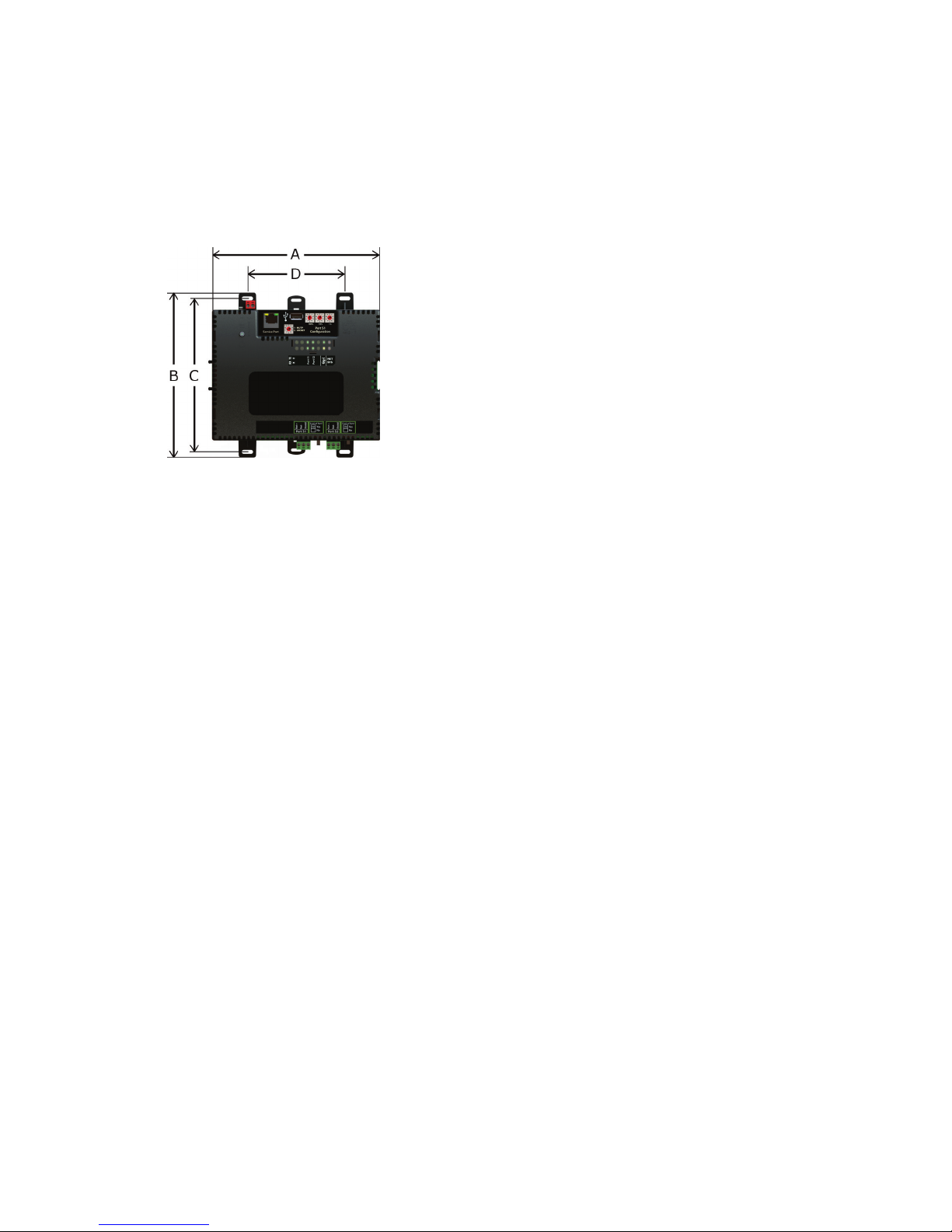
Overall dimensions A:
B:
Depth:
Screw mounting dimensions C:
D:
Recommended panel depth 6 in. (15.24 cm) minimum
7.1 in. (18.03 cm)
6.95 in. (17.65 cm)
2.79 in. (7.09 cm)
6.45 in (16.38 cm)
4.1 in. (10.4 cm)
Weight 1 lb. 1 oz. (0.482 kg)
BACnet Support Conforms to the BACnet Router (B-R-TR) Standard Device Profile as defined in
i-Vu® XT Router CARRIER CORPORATION ©2018
Installation and Start-up Guide All rights reserved
2
ANSI/ASHRAE Standard 135-2012 (BACnet) Annex L, Protocol Revision 9
Page 7

What is the i-Vu® XT Router?
Compliance
United States of America:
FCC compliant to Title CFR47, Chapter 1, Subchapter A, Part 15, Subpart B, Class
A; UL Listed to UL 916, PAZX, Energy Management Equipment
Canada:
Industry Canada Compliant, ICES-003, Class A
cUL Listed UL 916, PAZX7, Energy Management Equipment
Europe: Mark
EN50491-5-2:2009; Part 5-2: EMC requirements for HBES/BACS used in
residential, commercial and light industry environment
EN50491-3:2009, Part 3: Electrical safety requirements for Home and Building
Electronic Systems (HBES) and Building Automation and Control Systems (BACS)
Low Voltage Directive: 2014/35/EU
RoHS Compliant: 2011/65/EU
Australia and New Zealand:
C-Tick Mark, AS/NZS 61000-6-3
i-Vu® XT Router CARRIER CORPORATION ©2018
Installation and Start-up Guide All rights reserved
3
Page 8
To mount the i-Vu® XT Router
To mount the i-Vu® XT Router
The i-Vu® XT Router must be mounted in a metal enclosure or cabinet which is properly rated for the location
where it is being installed.
DIN rail mount
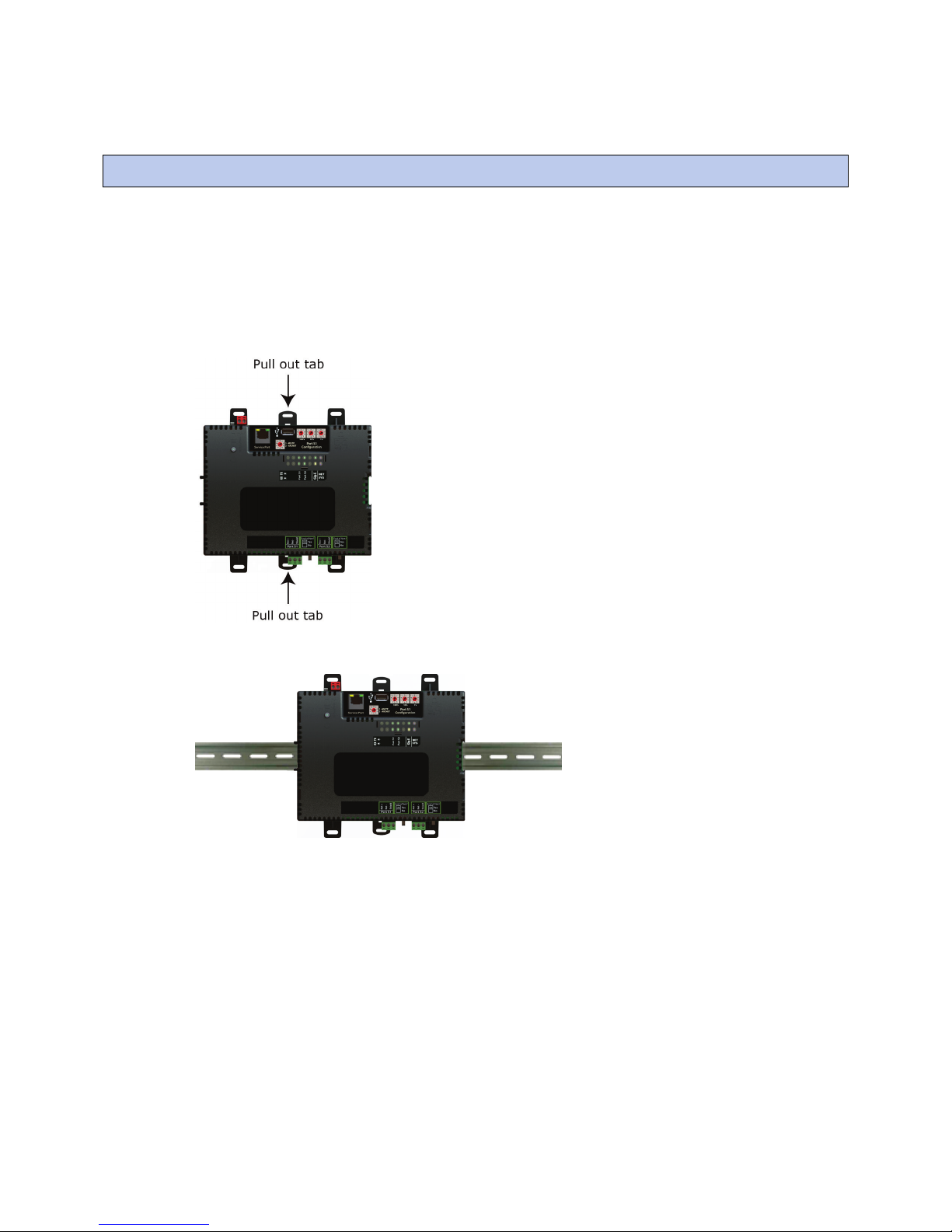
1 Push down and pull out the center tabs shown below to clear the din rail trough on the back of the router.
2 Place the router on the DIN rail so that the rail is in the trough on the back of the router.
3 Push the center tabs towards the router until you hear them click.
4 Pull gently on the router to verify that it is locked in place.
i-Vu® XT Router CARRIER CORPORATION ©2018
Installation and Start-up Guide All rights reserved
4
Page 9
To mount the i-Vu® XT Router
Screw Mount
Leave about 2 in. (5 cm) on each side of the router for wiring.
Insert #6 screws through the mounting holes. Use no more than 8 in.lbs. torque to secure plastic tab to mounting
surface.
A:
B:
C:
D:
Depth:
7.1 in. (18.03 cm)
6.95 in. (17.65 cm)
6.45 in. (16.38 cm)
4.1 in. (10.4 cm)
2.79 in (7.09 cm)
i-Vu® XT Router CARRIER CORPORATION ©2018
Installation and Start-up Guide All rights reserved
5
Page 10

Wiring for power
WARNING
CAUTIONS
To wire for power
OFF
24 Vac/Vdc (+/-
Wiring for power
• The i-Vu® XT Router is powered by a Class 2 power source. Take appropriate isolation measures when
mounting it in a control panel where non-Class 2 circuits are present.
• Carrier controllers can share a power supply as long as you:
• Maintain the same polarity.
• Use the power supply only for Carrier controllers.
Do not apply line voltage (mains voltage) to the router's ports and terminals.
1 Make sure the i-Vu® XT Router’s power switch is in the
you can verify the correct voltage.
2 Remove power from the power supply.
3 Pull the red screw terminal connector from the router's power terminals labeled
4 Connect the power supply's wires to the red screw terminal connector.
5 Connect an 18 AWG or larger wire from the power supply's negative (-) terminal to earth ground. This wire
must not exceed 12 in. (30.5 cm).
6 Apply power to the power supply.
7 Measure the voltage at the red screw terminal connector to verify that the voltage is within the operating
range of 20 to 30 Vac or 23.4 to 30 Vdc.
8 Insert the red screw terminal connector into the router's power terminals.
9 To verify the polarity of the wiring, measure the voltage from the negative terminal of the red screw terminal
connector to a nearby ground. The reading should be 0V.
10 Turn on the router's power switch.
position to prevent it from powering up before
).
11 Verify that the LED on top of the router is on.
12 Measure the voltage at the red screw terminal connector to verify that the voltage is within the operating
range of 20 to 30 Vac or 23.4 to 30 Vdc.
i-Vu® XT Router CARRIER CORPORATION ©2018
Installation and Start-up Guide All rights reserved
6
Page 11

Addressing the i-Vu® XT Router
Set this port's address ...
In this location...
See...
Service Port
Rotary switch settings
Default IP address
Addressing the i-Vu® XT Router
IP Service Port To set the IP address
Port S1 On the router's
rotary switches
Port S2 Service Port To set the Port S2 address and baud rate (page
To access the controller setup through the
1 Connect an Ethernet cable from a computer to the router as shown below.
2 If your computer uses a static IP address, set the address to 169.254.1.x, where x is 2 or greater. If it uses a
DHCP address, leave the address as it is.
3 Turn off the computer's Wi-Fi if it is on.
4 Open a web browser on the computer.
5 Navigate to http://local.access or http://169.254.1.1 to see the controller setup pages.
See To set up the controller through the Service Port (page 25) for general information on using the controller
setup pages.
To set the Port S1 address and baud rate (page
10)
10)
:
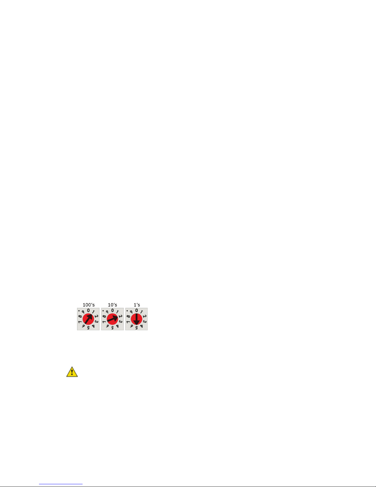
Rotary switch settings (see example below) are used to determine the following items in your system, so you
should plan carefully before setting the switches.
• If you use a
be a unique number from 1 to 253). See To set the IP address (page
i-Vu® XT Router CARRIER CORPORATION ©2018
Installation and Start-up Guide All rights reserved
7
, the final octet is the number created by the three rotary switch settings (must
8).
Page 12

Addressing the i-Vu® XT Router
Device Instance
BACnet Network Number
EXAMPLE
CAUTION
To set the IP address
Use a...
If...
DHCP IP Address
Custom Static IP Address
Have any third-party IP devices?
Default IP Address
NOTE
• If you autogenerate the following:
, the number is automatically set to a number equal to the ((IP network number x 100) +
rotary switch settings).
for the ARC/MSTP port, the number is automatically set to a number equal to the
((IP network number + rotary switch settings) x 10).
Autogenerating is set up through the controller setup pages (page 25).
• The rotary switch settings determine the router number in the i-Vu interface.
The switches below are set to 125.
Do not leave the rotary switches set at 0 (the factory default). The i-Vu® XT Router cannot be
discovered if the rotary switches are left at 0.
You must define the i-Vu® XT Router's IP addressing (IP address, subnet mask, and default gateway) in the
controller setup pages so that the router can communicate with the i-Vu Pro Server on the IP network.
Use one of the IP addressing schemes described below with the associated instructions that follow.
generated by a DHCP server
from your network administrator
that your system creates
Carefully plan your addressing scheme to avoid duplicating addresses. If third-party devices are integrated
into the system, make sure your addresses do not conflict with their addresses.
i-Vu® XT Router CARRIER CORPORATION ©2018
Installation and Start-up Guide All rights reserved
8
The IP network uses a DHCP server for IP addressing
You do not use a DHCP server and the answer to any of the
following questions is yes. Will the i-Vu® system:
• Share a facility's existing IP data network?
• Have 199 or more Carrier IP devices, or 254 or more devices
with static IP addresses?
• Be connected to the Internet?
• Have at least one device located on the other side of an IP
router?
•
The answer to all of the above questions is no.
Page 13
Addressing the i-Vu® XT Router
Modstat
Ethernet MAC address
Ports
IP Port
DHCP
Save
IP Address
Ports
IP Port
Custom Static
IP Address, Subnet Mask
Default Gateway
Save
x
EXAMPLE
Ports
IP Port
Default IP Address
Save
CAUTIONS
To set a DHCP IP address
1 On the controller setup pages
2 On the
3 Click
4 Write down the
5 Give the DHCP network administrator the IP address and Ethernet MAC address and ask him to reserve that
tab under
.
IP address for the router so that it always receives the same IP address from the DHCP server.
.
, select
tab, find the router’s
.
and write it down.
To set a custom IP address
1 Obtain the IP address, subnet mask, and default gateway address for the router from the facility network
administrator.
2 On the controller setup pages
3 Enter the
you.
4 Click
.
tab under
, and
, select
addresses that the network administrator gave
.
To set a default IP address
Default IP addressing assigns the following to the router:
• IP address = 192.168.168.x
where
is the setting on the rotary switches in the range from 1 to 253
• Subnet mask = 255.255.255.0
• Default Gateway = 192.168.168.254
1 Set the router's three rotary switches to a unique address on the network. Set the left rotary switch to the
hundreds digit, the middle switch to the tens digit, and the right switch to the ones digit.
The switches below are set to 125.
2 On the controller setup pages
3 Click
• The Default IP address range is 1 to 253. Setting the rotary switches to 0 will set the Default IP address to 1.
.
Setting the switches to 255 will set the Default IP to 253. Do not set the switches to 254.
i-Vu® XT Router CARRIER CORPORATION ©2018
Installation and Start-up Guide All rights reserved
9
tab under
, select
.
Page 14

Addressing the i-Vu® XT Router
Ports
Ports
Update IP Address
Find Devices
Upload All
Content
NOTE
To set the Port S1 address and baud rate
Port address
For MS/TP, set the port's baud rate
Ports
S1 Port
MSTP Baud Rate
NOTE
Save
To set the Port S2 address and baud rate
Ports
Port S2
Port S2 Address
Baud Rate
NOTE
Save
• If you set the Default IP address controller setup
one of the following to correct the IP address in the router:
• Go to the controller setup
tab and click the
• Cycle the router's power.
You will then need to correct the IP address in the i-Vu® application using
. See the i-Vu® Help for more information.
The default address is an intranet address. Data packets from this address are not routable to the Internet.
• For ARCNET, you cannot change the default address of 254.
• For MS/TP, you cannot change the default address of 0.
1 On the controller setup
2 Click
tab under
, select the
Use the same baud rate for all devices on the MS/TP network.
.
tab and then change the rotary switches, you must do
.
. The default is 76,800 bps.
and
1 On the controller setup
must be in the range 0 to 127.
2 Select the MS/TP network's
Use the same baud rate for all devices on the MS/TP network.
3 Click
.
i-Vu® XT Router CARRIER CORPORATION ©2018
Installation and Start-up Guide All rights reserved
10
tab under
, type the address in the
. The default is 76,800 bps.
field. The address
Page 15

Wiring for communications
Port Protocol
Port type(s)
Speed(s)
Gig-E
Port S1
Port S1
Port S2
Service Port
USB Port
Port S1 Configuration
0
1
2
Wiring specifications
For...
Use...
Maximum Length
WARNING
Wiring for communications
The i-Vu® XT Router communicates on the following ports.
BACnet/IP Ethernet 10 Mbps
1
1
BACnet/ARCNET RS485 156 kbps
BACnet/MSTP RS485 9600 bps
or
HTTP/IP
Ethernet
2
USB2.0 USB
1
Set the
2
See To set up the router through the Service Port.
if the port is not used
for MS/TP
for ARCNET
rotary switch to:
100 Mbps
1000 Mbps
19.2 kbps
38.4 kbps
57.6 kbps
76.8 kbps (default)
115.2 kbps
10 Mbps
100 Mbps
Ethernet CAT5e or higher Ethernet cable 328 feet (100 meters)
ARCNET 22 AWG, low-capacitance, twisted, stranded,
shielded copper wire *
MS/TP 22 AWG, low-capacitance, twisted, stranded,
shielded copper wire *
*
See the Open Controller Network Wiring Guide.
i-Vu® XT Router CARRIER CORPORATION ©2018
Installation and Start-up Guide All rights reserved
11
Do not apply line voltage (mains voltage) to the router's ports and terminals.
2000 feet (610 meters)
2000 feet (610 meters)
Page 16

Wiring for communications
To connect the i-Vu® XT Router to the Ethernet
NOTES
BBMD Configuration Tool
Broadcast Distribution Table
Connect an Ethernet cable to the Gig-E Ethernet port.
If your system has multiple routers that reside on different IP subnets, you must set up one router on each IP
subnet as a BACnet/IP Broadcast Management Device (BBMD).
Every subnet with a router must have a BBMD configured in order for broadcasts from routers on that subnet to
reach the rest of the routers on the network.
• The i-Vu® Standard or Plus application - If the i-Vu® web server is on a separate subnet than the rest of the
routers, the internal router must be assigned an IP address and configured as a BBMD.
• The i-Vu® Pro application - If the i-Vu® Pro server is on a separate subnet than the rest of the routers, you
must register it as a foreign device.
Use the
• Define the
• Allow controllers on one subnet to communicate with controllers on other subnets
to:
(BDT) in each BBMD
• Enable the i-Vu® application to see, upload, or configure controllers on different subnets
i-Vu® XT Router CARRIER CORPORATION ©2018
Installation and Start-up Guide All rights reserved
12
Page 17

Wiring for communications
To wire to a BACnet/ARCNET network
off
ARC/MSTP
Net +, Net -
GND
NOTE
MSTP / ARCNET
End of Net
Yes
NOTE
End of Net
NOTE
To wire to a BACnet MS/TP network
ARC/MSTP
MSTP
off
ARC/MSTP
MSTP
Net +, Net -
GND
NOTE
ARC/MSTP
MSTP / ARCNET
NOTE
ARC/MSTP
End of Net
Yes
NOTE
End of Net
NOTE
1 Turn
the i-Vu® XT Router's power.
2 Check the communications wiring for shorts and grounds.
3 Connect the communications wiring to the
Use the same polarity throughout the network segment.
4 Set the
rotary switch to 2.
5 If the i-Vu® XT Router is at either end of a network segment, set the port's
The router’s
switch applies network termination and bias. See the Open Controller Network
Wiring Guide.
6 Turn on the router's power.
7 To verify communication with the network, get a Module Status report in the i-Vu® interface for a controller
on the ARCNET network.
This step requires that you have discovered and uploaded the router in the i-Vu® application.
An MS/TP network can be wired to either the
1 Turn
the i-Vu® XT Router's power.
2 Check the communications wiring for shorts and grounds.
3 Connect the communications wiring to the
and
.
Use the same polarity throughout the network segment.
4 If you are using the
If the
port, set the
port is not being used for any network, set this rotary switch to 0.
5 If the i-Vu® XT Router is at either end of a network segment, set the port's
The router’s
switch applies network termination and bias.
6 Turn on the router's power.
7 To verify communication with the network, get a Module Status report in the i-Vu® interface for a controller
on the MS/TP network.
This step requires that you have discovered and uploaded the router in the i-Vu® application.
port’s screw terminals labeled
port or the
or
port.
port’s screw terminals labeled
rotary switch to 1.
switch to
switch to
, and
.
.
.
,
i-Vu® XT Router CARRIER CORPORATION ©2018
Installation and Start-up Guide All rights reserved
13
Page 18

Find and upload in the i-Vu® interface
Devices
Manage
Find Devices
Manage
Upload All Content
Ctrl+click, Shift+click
This will upload all content for the controller. Are you sure you want to
do this?
Status
NOTES
Find and upload in the i-Vu® interface
1 In the i-Vu® interface, select the system level in the navigation tree.
2 On the
3 Once routers are found, select one or more routers in the list on the
4 Click OK when you see the message
page >
to upload to the i-Vu® application. Use
tab, click
to discover your routers.
tab and click
, or both to select multiple items.
○ If an error message appears, click on the message to view an explanation.
○ For details, see the i-Vu® Help.
. When complete, a check mark under
indicates a successful upload.
i-Vu® XT Router CARRIER CORPORATION ©2018
Installation and Start-up Guide All rights reserved
14
Page 19

Adjusting the i-Vu® XT Router driver properties
Driver Properties
Driver Properties
Driver
Driver
Update
Driver
Settings
Controller Clock
Clock Fail Date and Time
Time Synch Sensitivity
(seconds)
Debug
Enable Debug Messages
Device
Device
Adjusting the i-Vu® XT Router driver properties
After you find and upload the i-Vu® XT Router in the i-Vu® interface, you may want to customize the i-Vu® XT
Router's settings for your applications. You can change settings on the
1 In the i-Vu® interface, right-click the i-Vu® XT Router in the navigation tree and select
2 Adjust the driver as desired.
page.
.
On the
page >
tab, you can:
• Obtain information about the i-Vu® XT Router, get a Modstat, and device logs
• Add, update, or delete drivers
The
page >
• The date/time of last parameter change or the last time the database was archived
• If control programs, properties, and schedules were successfully stored in memory
• Undelivered Alarm Status
tab provides the following information plus the items described in the table below:
The
• BACnet device object properties for the i-Vu® XT Router
• Status of the BACnet communication
• The character sets supported by this device for BACnet communication
Date and time the router uses when its real-time clock is invalid.
When the router receives a time sync request, if the difference between the
page provides the following information plus the items described in the table below:
router's time and the time sync's time is greater than this field's value, the router's
time is immediately changed. If the difference is less than this field's value, the
router's time is slowly adjusted until the time is correct.
Enable only if directed by Carrier Controls System Support.
i-Vu® XT Router CARRIER CORPORATION ©2018
Installation and Start-up Guide All rights reserved
15
Page 20

Adjusting the i-Vu® XT Router driver properties
Configuration
BACnet System Status
APDU Timeout
APDU Segment Timeout
Number of APDU Retries
Controller Clock
Time Broadcaster will
synchronize time every ____
Time Synchronization
Recipients
Add
Device ID
Address
Recipient Type
Accept
Notification Classes
Priorities
NOTE
Priority range
Network message priority
The current state of the router:
Operational
Download in Progress
Download Required
Backup in Progress
Non-Operational
The following three fields refer to all networks over which the i-Vu® XT Router communicates.
How many milliseconds the device will wait before resending a message if no
response is received.
How many milliseconds the device will wait before resending a message segment
if no response is received.
The number of times the device will resend a message.
If you have third-party BACnet devices on one of the router's networks, you can
have the router send a BACnet time sync to those devices at the interval you
define in this field.
To define third-party BACnet devices as Time Synchronization Recipients:
1 Click
2 Select
.
or
in the
field.
3 Enter the Device ID or Address information.
4 Click
.
A BACnet alarm's Notification Class defines:
• Alarm priority for Alarm, Fault, and Return to Normal states
• Options for BACnet alarm acknowledgment
• Where alarms should be sent (recipients)
Alarms in the i-Vu® application use Notification Class #1. The i-Vu® application is automatically a recipient of
these alarms.
00–63 Life Safety
64–127 Critical Equipment
128–191 Urgent
192–255 Normal
BACnet defines the following Network message priorities for Alarms and
Events.
i-Vu® XT Router CARRIER CORPORATION ©2018
Installation and Start-up Guide All rights reserved
16
Page 21

Adjusting the i-Vu® XT Router driver properties
Priority of Off-Normal
Priority of Fault
Priority of Normal
Ack Required for Off-Normal,
Fault, and Normal
TIP
Alarm
Enable/Disable
Recipient List
Recipients
Add
Recipient Description
Recipients
Recipient Type
Address
Issue Confirmed
Notifications). This use is rare.
Recipient Device Object
Identifier
Device Instance
Process Identifier
Issue Confirmed
Notifications
Transitions to Send
Calendars
Schedules
BACnet priority for Alarms.
BACnet priority for Fault messages.
BACnet priority for Return-to-normal messages.
Specifies whether alarms associated with this Notification Class require a BACnet
Acknowledgment for Off-Normal, Fault, or Normal alarms.
You can require operator acknowledgment for an Alarm or Return-to-
normal message (stored in the i-Vu® database). In the i-Vu® interface on the
>
source or an alarm category.
tab, change the acknowledgment settings for an alarm
The first row in this list is the i-Vu® application. Do not delete this row. Click
you want other BACnet devices to receive alarms associated with this Notification
Class.
if
Days and times The days and times during which the recipient will receive alarms.
Calendars are provided in the driver for BACnet compatibility only. Instead, use the
interface.
Name that appears in the
Use
Change for third-party devices that use a BACnet Process Identifier other than 1.
Uncheck the types of alarms you do not want the recipient to get.
table.
(static binding) for either of the following:
• Third-party BACnet device recipients that do not support dynamic binding
When you want alarms to be broadcast (you must uncheck
•
Type the
in the # field.
The i-Vu® application processes alarms for any 32-bit Process Identifier.
Select to have a device continue sending an alarm message until it receives
delivery confirmation from the recipient.
feature in the i-Vu®
i-Vu® XT Router CARRIER CORPORATION ©2018
Installation and Start-up Guide All rights reserved
17
Page 22

Adjusting the i-Vu® XT Router driver properties
Common and Specific Alarms
Common alarm:
Specific alarm:
• Controller Halted
Duplicate Address
• Dead Controller Timeout
NOTE
Controller Generated Alarm
Description
Alarms
Events
Alarm Category and Alarm
Template
Enable
Notification Class
BACnet router properties
CAUTION
BACnet firewall
On these pages, you can enable/disable, change BACnet alarm properties, or set delays for the following BACnet
alarms:
•
To set up alarm actions for controller generated alarms, see Setting up alarm actions in the i-Vu® Help.
Short message shown on the
Clear these checkboxes to disable Alarm or Return to normal messages of this
In a typical i-Vu® system, the Notification Class is 1; however, if needed, you can
controller setup pages (page
Do not change the settings on this page as it will result in communication failure. Use the
25) to change settings and then resolve mismatches in the i-Vu® application.
page or in an alarm action when this type of
alarm is generated.
See Customizing alarms in i-Vu® Help.
type from the i-Vu® XT Router.
associate a different notification class with the alarm. See Notification Classes to
set up alarm delivery options for a specific Notification Class.
If this IP router is accessible from the Internet, you can increase security by enabling its BACnet firewall. When
enabled, this feature prevents the router from receiving BACnet messages from unidentified sources and allows
communication only with IP addresses that you define. These can be all private IP addresses and/or a list of IP
addresses. Follow the instructions in the i-Vu® interface to set up the BACnet firewall.
i-Vu® XT Router CARRIER CORPORATION ©2018
Installation and Start-up Guide All rights reserved
18
Page 23

Adjusting the i-Vu® XT Router driver properties
Network Diagnostics - Statistics
Trends > Enabled Points
Reset
Router Statistics
Error Counters
Dropped Packets
Route Not Found
Route Unreachable
Network Activity
Router Sourced Packets
Network Activity
Trends
Router Error Rate
Router Packet Rate
Gig-E Port Statistics
BACnet/IP Statistics
BACnet/IP Rx Unicast Packets
BACnet/IP Tx Unicast Packets
BACnet/IP Rx Broadcast Packets
BACnet/IP Tx Broadcast Packets
Whitelist Rejections
This page shows the network statistics for each of the i-Vu® XT Router's ports that are in use. This same
information is provided in a Module Status report (page 32).
Click a link at the bottom of each section to see the statistics displayed as trend graphs. You can also access
these trends by clicking on the driver in the network tree, and then selecting
desired trend graph.
Click a port's
button to set all of the numbers to zero so the counting can start over.
network does not exist.
either busy or offline
Shows the number of incoming and outgoing unicast and broadcast packets for
each of the i-Vu® XT Router's networks.
Shows the number of packets initiated by the i-Vu® XT Router that are not in
response to a request from another device. The numbers in this table will also
appear in the appropriate columns in the
interval.
received within the trend sampling interval.
device.
BACnet device.
i-Vu® XT Router.
the i-Vu® XT Router.
by the BACnet Firewall because the IP address that sent the message was not in
the whitelist.
—Data packets that could not be delivered.
—Packets that could not be delivered because the requested
—These are routed packets whose destination network is
—Shows the total number of errors within the trend sampling
—Shows the total number of packets transmitted and
—BACnet/IP packets received from a single BACnet
—BACnet/IP packets transmitted to a single
—BACnet/IP broadcast packets received by the
—BACnet/IP broadcast packets transmitted by
(if BACnet Firewall (page 18) is enabled)—Messages blocked
tab.
> and the
i-Vu® XT Router CARRIER CORPORATION ©2018
Installation and Start-up Guide All rights reserved
19
Page 24

Adjusting the i-Vu® XT Router driver properties
Ethernet Statistics
Ethernet Rx packets
Ethernet Tx packets
Receive Errors (total)
Transmit Errors (total)
Dropped Packets
Trends
Gig-E Error Rate
Gig-E Packet Rate
Port S1 Statistics
Error Counters
Node Reconfiguration
Bus Reconfiguration
Excessive NACK
Dropped Packets
Activity Counters
BACnet/ARCNET Rx Packets
BACnet/ARCNET Tx Packets
Trends
ARC Error Rate
ARC Packet Rate
Port S1 Statistics
Port S2 Statistics
Error Counters
UART Errors
Invalid Frames
Dropped Packets
Dropped Tokens
No responses—
when used for ARCNET
when used for MSTP
or
—All packets (including non-BACnet packets such as a ping)
received by the i-Vu® XT Router.
—All packets (including non-BACnet packets such as a ping)
transmitted by the i-Vu® XT Router.
—All errors related to received packets such as CRC errors,
FIFO errors, frame errors, length errors, missed errors, and overrun errors.
—All errors related to transmitted packets such as aborted
errors, carrier errors, dropped errors, FIFO errors, heartbeat errors, and window
errors.
—Packets dropped by the i-Vu® XT Router's Ethernet interface.
—Shows the total number of errors within the interval time.
—Shows the total number of packets transmitted and received
within the trend sampling interval
—The ARCNET reconfigurations initiated by the i-Vu® XT
Router.
—An ARCNET reconfiguration not generated by the i-Vu® XT
Router (such as when a controller connects to the network).
—Excessive NACKs received by the i-Vu® XT Router's ARCNET
chip. Excessive NACKs are usually the result of a station which is unable to
process a steady stream of packets due to buffer overflows or slow responses.
—Dropped receive and transmit frames. These may be dropped
due to buffer allocation failures, length errors, or NACKed transmit packets.
—BACnet/ARCNET data packets received by the i-
Vu® XT Router.
—BACnet/ARCNET data packets transmitted by the i-
Vu® XT Router.
—Total number of errors within the interval time on this network,
including break errors, framing errors, etc..
—BACnet/ARCNET data packets transmitted through router, not
the total utilization.
i-Vu® XT Router CARRIER CORPORATION ©2018
Installation and Start-up Guide All rights reserved
20
—UART receive and transmit errors such as break errors, framing
errors, parity errors, and overrun errors.
—Received MS/TP frames that contain an error such as CRC.
—Dropped receive and transmit frames. These may be dropped
due to buffer allocation failures, length errors, or APDU timeouts (in the case of
transmit frames)
—Dropped tokens that have been retransmitted.
Messages that did not receive a response from the destination
device.
Page 25

Adjusting the i-Vu® XT Router driver properties
Activity Counters
BACnet/MSTP Rx Packets
BACnet/MSTP Tx Packets
Latency
Average Value (milliseconds)
Maximum Value (milliseconds)
Trends
MSTP Error Rate
MSTP Network Utilization
NOTE
Network Diagnostics - Packet Capture
Start/Stop
Start
Accept
NOTE
Get capture file
Start capture:
At (mm/dd/yyyy hh:mm AM/PM)
Start
NOTE
Continuous
Start
Accept
Save
Start/Stop
Continuous
Router.
XT Router.
be transmitted until it is actually transmitted on the bus.
queued to be transmitted until it is actually transmitted on the bus
—Total number of errors within the interval time on this network,
including break errors, framing errors, etc.
data packets.
This is for all bus traffic, not just traffic generated by the i-Vu® XT Router.
This page allows you to capture network communication on a port and then download the capture file for
troubleshooting. Choose one of the following capture options:
•
capture stops, the capture file is generated.
Start/Stop captures have completed.
○
○
- Define the start and stop criteria, and then click
If a Start/Stop capture is running on any other port, the
, the packet capture begins at the date and time you specified.
The hours field is validated from 0 to 12, and minute field is validated from 0 to 59.
- When you check
- Click
and
to begin the capture. Click
create the capture file. The capture will automatically resume. Click on the
capture.
—BACnet/MSTP data packets received by the i-Vu® XT
—BACnet/MSTP data packets transmitted by the i-Vu®
—The average time from when a packet is queued to
—The maximum time from when a packet is
—Percentage of total bus bandwidth used to transmit
and
to begin the capture. When the
button will be disabled until all
, enter the time and date, and click
to momentarily stop the capture and
option to end the
i-Vu® XT Router CARRIER CORPORATION ©2018
Installation and Start-up Guide All rights reserved
21
Page 26

Adjusting the i-Vu® XT Router driver properties
Packet Capture
Get capture file
OK
NOTE
Get capture file
captures
NOTES
mstpcap0
mstpcap1
Get capture file
To download the capture file
Capture files are Wireshark files that are added to the Device Log Archive .tgz file. Do the following to view the
files.
1 If you do not have Wireshark installed on your computer, download the latest version from the Wireshark
website (http://www.wireshark.org).
2 Run the install program, accepting all defaults. Include WinPcap in the installation.
3 On the i-Vu®
"Retrieving the file, this may take a little while". Click
If the size of the .tgz is large, there could be a considerable delay (for example, over 2 minutes) after
you click
4 Open the .tgz file. The files are in the
page, click
to download the .tgz file. The message appears
.
until your browser begins the download.
folder.
Capture file names are based on the ports.
• If you have an MSTP capture file for both Port S1 and Port S2, the file names will be:
• Clicking
for Port S1
for Port S2
generates the port's .pcap file. If the port has a .pcap file from a previous
capture, that file will be overwritten.
5 Extract the .pcap file from the .tgz file.
6 Open the .pcap file in Wireshark.
i-Vu® XT Router CARRIER CORPORATION ©2018
Installation and Start-up Guide All rights reserved
22
Page 27

Adjusting the i-Vu® XT Router driver properties
Communication Status
Protocols
To set up Network Statistic trends
PREREQUISITE
Network
Driver
Network Diagnostics
Statistics
Driver
Trends
Enabled Points
Configure
Enable/Disable
Field
Notes
Sample every _:_:_ (hh:mm:ss)
Sample on COV
(change of value)
COV Increment
Sample every
COV Increment
Max samples
NOTE
Reset
Stop When Full
Enable trend log at specific
times only
Enable Trend Historian
Store Trends Now
Write to historian every __ trend
samples
NOTE
The
page shows the status of the protocols currently running on the i-Vu® XT Router.
cumulative patch.
To view the Network Statistics (page 19) as trend graphs, go to one of the following on the i-Vu®
• Under
• On the
You can define:
• How the graph looks on the trend's
• How you want trend samples to be collected on the
To view Network Statistic trends, you must have a i-Vu® v6.5 or later system with the latest
, on the
Network Statistic trends have a non-configurable maximum trend log buffer
Check this field to stop trend sampling when the maximum number of
page, click the
Archives trend data to the system database.
Writes all trend data in the router to the system database without having to
(Recommended method) To record the value at a regular time interval, enter
hh:mm:ss in this field.
To record the value only when the value changes by at least the amount of
the
in the
size of 1440.
samples currently stored in the router.
samples is reached.
Collects trend data for the specific period of time you define in the time and
date fields.
enable trend historian.
Writes all trend data in the router to the system database each time the
router collects the number of samples that you enter in this field. This
number must be greater than zero and less than the number entered in the
Max samples field. The number of trends specified must be accumulated at
least once before the historical trends can be viewed.
power.
>
drop-down button, select
Any trends not stored in the historian will be lost if the router loses
tab.
Trending consumes memory in the router. Click
page, click a Trend link at the bottom of each section.
, set the
field.
tab. See table below.
and then the graph you want.
field to 0:00:00 and enter a value
to delete all
tree:
i-Vu® XT Router CARRIER CORPORATION ©2018
Installation and Start-up Guide All rights reserved
23
Page 28

Adjusting the i-Vu® XT Router driver properties
Field
Notes
Trend samples accumulated
since last notification
Last Record Written to Historian
Keep historical trends for __
days
System Settings
General
Shows the number of samples stored in the router since data was last
written to the database.
Shows the number of trend samples that were last written to the database.
This is based on the date that the sample was read. Select the first option to
use the system default that is defined on the
>
Select the second option to set a value for this trend only.
tab.
i-Vu® XT Router CARRIER CORPORATION ©2018
Installation and Start-up Guide All rights reserved
24
Page 29

To set up the controller through the Service Port
NOTE
ModStat tab
To set up the controller through the Service Port
Using a computer and an Ethernet cable, you can communicate with the i-Vu® XT Router through a web browser
to:
• View the router's Module Status report
• View/change router and network settings. Changes take effect immediately.
• Troubleshoot
1 Connect an Ethernet cable from a computer to the router as shown below.
2 If your computer uses a static IP address, set the address to 169.254.1.x, where x is 2 or greater. If it uses a
DHCP address, leave the address as it is.
3 Turn off the computer's Wi-Fi if it is on.
4 Open a web browser on the computer.
5 Navigate to http://local.access or http://169.254.1.1 to see the controller setup pages.
The first time you access the router in the i-Vu® interface after you have changed settings through the
Service Port, be sure to upload the changes to the system database. This will preserve those settings when you
download memory or parameters to the router.
This tab provides the router's Module Status report that gives information about the router and network
communication status. See Appendix - Module Status field descriptions (page 37).
i-Vu® XT Router CARRIER CORPORATION ©2018
Installation and Start-up Guide All rights reserved
25
Page 30

To set up the controller through the Service Port
Device tab
BACnet Object
Device Instance
Autogenerated
Assigned
Device Name
Autogenerated
Assigned
Device Location
Device Description
Configuration
APDU Timeout
APDU Segment Timeout
APDU Retries
Controller Information
Clear Counts/Logs
Ports tab
IP Port
IP Addressing
Port S1
End of Network
End of Net?
Active Protocol
MAC Address
Port S2
End of Network
End of Net?
Active Protocol
the (IP network number) x 100 + rotary switch address.
device + the Device Instance. For example, device2423911.
You can enter an intuitive location for the device in the i-Vu® interface.
You can enter an intuitive description for the device in the i-Vu® interface.
How many milliseconds the device will wait before resending a message if no
response is received.
How many milliseconds the device will wait before resending a message segment
if no response is received.
The number of times the device will resend a message.
—(Default) The Device ID is automatically set to a number equal to
—Lets you enter a specific number that is unique on the BACnet network.
—(Default) The Device Name is automatically set as the word
—Lets you enter a specific name that is unique on the BACnet network.
Clears Reset counters and the three message history fields from the Module
Status.
Select the type of addressing the router is to use. See Addressing the i-Vu® XT
Router (page 7).
Indicates status of the router's
switch.
Indicates status of the router's Port S1 rotary switch.
0=Disabled
1=MS/TP
2=ARCNET
3=Modbus
The address that is set on the three rotary switches. See To set the Port S1
address and baud rate (page 10).
Indicates status of the router's
The protocol that has been enabled for Port S2 on the BACnet or Modbus tab.
i-Vu® XT Router CARRIER CORPORATION ©2018
Installation and Start-up Guide All rights reserved
26
switch.
Page 31

To set up the controller through the Service Port
BACnet tab
IP Port
BACnet Network Number
Disable Routing
Autogenerated
Assigned
BACnet UDP Port
Enable NAT Routing
For future use.
Global NAT IP Address
For future use.
Global NAT BACnet UDP Port
For future use.
BACnet Secondary IP Net
Number
Private
side
BACnet
router
Public
side
N
A
T
R
Co
ntro
lle
r
Secondary IP
network
C
BACnet Secondary UDP Port
BACnet UDP Port
Ethernet Port
MAC Address
Gig-E
BACnet Network Number
Port S1
End of Network
End of Net?
Active Protocol
MAC Address
ARCNET Baud Rate
MSTP Baud Rate
The port that the i-Vu® application will use for BACnet communication.
—Select if the IP port is not used.
—The BACnet/IP network number is automatically set to 1600.
—Lets you enter a specific number.
Check if the i-Vu® XT Router is behind a NAT router (firewall).
Public IP address of the NAT router.
Port number assigned to the NAT router's public interface.
If the i-Vu® XT Router has two BACnet/IP networks communicating on the Gig-E
port, enter the second IP network number in this field.
If the i-Vu® XT Router is behind a NAT router and there is a second network with
BACnet/IP devices behind the NAT router, enter the second network number in
this field to logically connect the i-Vu® XT Router to the devices on the second
network.
If the i-Vu® XT Router has two BACnet/IP networks communicating on the Gig-E
port, enter the port number that the i-Vu® application will use for BACnet
communication. This port must be different than the
A factory assigned Ethernet MAC Address for the
Specify a number for the BACnet/Ethernet network or set to 0 if the port is not
used.
.
port.
Indicates status of the router's
Indicates status of the router's Port S1 rotary switch.
The address that is set on the three rotary switches. See To set the Port S1
156000
Set this to a baud rate that all other devices on the MS/TP network are set to.
i-Vu® XT Router CARRIER CORPORATION ©2018
Installation and Start-up Guide All rights reserved
27
0=Disabled
1=MS/TP
2=ARCNET
3=Modbus
address and baud rate (page 10).
switch.
Page 32

To set up the controller through the Service Port
MSTP Max Master
MSTP Max Info Frames
TIP
Max Info Frames
BACnet Network Number
Disable Routing
Autogenerated
Assigned
Port S2
End of Network
End of Net?
Active Protocol
Modbus
Modbus
BACnet/MSTP
BACnet Network Number
Disabled if neither of the above have been done
MSTP Address
MSTP Baud Rate
MSTP Max Master
MSTP Max Info Frames
TIP
Max Info Frames
BACnet Network Number
Disable Routing
Autogenerated
Assigned
Home Network
To increase MS/TP performance, enter the highest address used on the MS/TP
network for a master controller. This number must be less than or equal to 127.
This is the maximum number of information messages a controller may transmit
before it must pass the token to the next controller. Valid values are 1 to 255.
Set
to a number in the range 20 to 100 so that the
router does not become a bottleneck for traffic being routed from a high speed
network to the slower MS/TP network.
Select:
if Port S1 is not used.
to have the network number for Port S1 automatically set to a
number equal to ((IP network number + rotary switch address) x 10).
to enter a specific number.
Indicates status of the router's
switch.
Shows one of the following:
•
•
if enabled on the
if you enter a
tab
below for an MS/TP
network
•
The router’s unique address on the MS/TP network.
Set this to a baud rate that all other devices on the MS/TP network are set to.
To increase MS/TP performance, enter the highest address used on the MS/TP
network for a master controller. This number must be less than or equal to 127.
This is the maximum number of information messages a controller may transmit
before it must pass the token to the next controller. Valid values are 1 to 255.
Set
to a number in the range 20 to 100 so that the
router does not become a bottleneck for traffic being routed from a high speed
network to the slower MS/TP network.
Select:
if Port S2 is not used.
to have the network number for Port S2 automatically set to a
number equal to ((IP network number + rotary switch address) x 10) + 3.
to enter a specific number.
This is typically the network that is communicating with the building automation
system's application. This sets the BACnet Address of the Device object.
i-Vu® XT Router CARRIER CORPORATION ©2018
Installation and Start-up Guide All rights reserved
28
Page 33

To set up the controller through the Service Port
Security tab
BACnet Firewall
Security
NOTE
If your BACnet Firewall configuration in the i-Vu® interface did not include the i-
Vu® server IP address, thus blocking communication with the i-Vu® server, you
can disable the router's BACnet Firewall on the controller setup
You can enable the BACnet Firewall only in the i-Vu® interface.
tab.
i-Vu® XT Router CARRIER CORPORATION ©2018
Installation and Start-up Guide All rights reserved
29
Page 34

Troubleshooting
LEDs
Color Pattern
Condition
Message in Module
Status
Possible Solutions
• Connect Ethernet Cable
components
port
• Use the controller setup
Ports
address
Troubleshooting
If you have problems mounting, wiring, or addressing the i-Vu® XT Router, contact Carrier Controls System
Support.
NET (Network Status) Tricolor LED
Red
Red
Red
On Ethernet connection problem No Ethernet Link
1 blink One of the following BACnet/IP
(Ethernet) DLL reporting issue:
• Unable to create tasks
•
2 blink Current default IP address does not
match the current rotary switch setting
Unable to open socket for BACnet
• Check other network
BACnet/IP error Cycle power
Default IP address
mismatch
address
• Cycle power to accept new
IP address
•
Change rotary switches to
match current default IP
tab to set the IP
i-Vu® XT Router CARRIER CORPORATION ©2018
Installation and Start-up Guide All rights reserved
30
Page 35

Troubleshooting
Color Pattern
Condition
Message in Module
Status
Possible Solutions
Invalid protocol selected
• Change rotary switch to
• Check that network cable
correct
• Check that network cable
correct
• Check the network
excessive COV traffic
Color Pattern
Condition
Message in Module
Status
Possible Solution
NET (Network Status) Tricolor LED
Blue
Blue
Blue
Blue
Blue
Blue
On One of the following issues:
• Port communication firmware did
• Port communication firmware is
•
1 blink Invalid address selected for protocol Invalid address selection
2 blink Router has same MAC address as
another connected device
3 blink Router is the only device on the
network
4 blink Excessive errors detected over 3
second period
5 blink ARCNET traffic overload possibly due
to circular router or excessive COVs
(change of values)
ARCNET/MSTP firmware
error
not load properly
not running
for ARCNET/MSTP
Duplicate address on
ARCNET/MSTP
No other devices
detected on
ARCNET/MSTP
Excessive
communication errors
on ARCNET/MSTP
Event System Error FPGA RX FIFO full
select valid protocol
• Cycle power
Change rotary switch to valid
address
Change rotary switch to unique
address
is connected properly
• Check that baud rate is
is connected properly
• Check that baud rate is
configuration for a circular
route
• Increase the time
between COVs to reduce
Green
On All enabled networks are functioning
properly
SYS (System Status) Tricolor LED
Red
Red
Red
Green
Green
2 blink Restarting after an abnormal exit Auto restart delay due to
4 blink Firmware image is corrupt Firmware error Download driver again
Fast
blink
1 blink No errors Operational No action required
2 blink Download of driver is in progress Download in progress No action required
Firmware error has caused the
firmware to exit and restart
i-Vu® XT Router CARRIER CORPORATION ©2018
Installation and Start-up Guide All rights reserved
31
No errors No action required
After 5 minute delay has
system error on startup
Fatal error detected No action required
expired, if condition occurs
again then cycle power
Page 36

Troubleshooting
Color Pattern
Condition
Message in Module
Status
Possible Solution
To get a Module Status report
Module Status
Properties
Module
Status
ModStat
To get a Device Log
Properties
Device Log
NOTE
Device Log Archive
SYS (System Status) Tricolor LED
Green
Green
Blue
Blue
Blue
3 blink BACnet Device ID is not set Download required Download the router
Fast
blink
On Router is starting up N/A No action required
Slow
blink
Fast
blink
Installation of recently downloaded
driver is occurring
Linux (operating system) is starting up N/A No action required
Linux is running but it could not start
the firmware application
A Module Status report provides information about the router and verifies proper network communication with the
router. You can get this report:
• In the i-Vu® application—Right-click the router on the navigation tree, then select
N/A No action required
N/A Download driver
.
• In the i-Vu® application—Select the router on the navigation tree. On the
.
• On the controller setup (page 25)
See Appendix - Module Status field descriptions (page 37).
If Carrier Controls System Support instructs you to get the router's Device Log containing diagnostic information
for troubleshooting:
1 Select the i-Vu® XT Router in the i-Vu® navigation tree.
2 On the
also contains any network packet captures that have been run from the Network Diagnostics - Packet Captures
(page
i-Vu® XT Router CARRIER CORPORATION ©2018
Installation and Start-up Guide All rights reserved
32
You can click
21) driver page.
page, click
tab.
.
to download a file containing multiple Device Logs to your computer. This
page, click
Page 37

Troubleshooting
To get the i-Vu® XT Router's serial number
Core
Main) board hardware
To replace the i-Vu® XT Router's fuse
Manufacturer
Mfr. Model #
If you need the router’s serial number when troubleshooting, the number is on:
• A Module Status report (Modstat) under
(or
• A sticker on the main board
See To get a Module Status report (page 32).
If you turn on the router’s power switch and the LED is not lit, the fuse that protects the router may be blown.
Remove the fuse and use a multimeter to check it.
The fuse is a fast acting, 250Vac, 2A, 5mm x 20mm glass fuse that you can purchase from one of the following
vendors:
Littelfuse 0217002.HXP
Bussmann S500-2-R
Belfuse 5SF 2-R
Optifuse FSD-2A
Before replacing the fuse, try to determine why the fuse blew. Check the power wiring polarity of the i-Vu® XT
Router and any other devices that share the power supply. Use the same polarity for all of them.
i-Vu® XT Router CARRIER CORPORATION ©2018
Installation and Start-up Guide All rights reserved
33
Page 38

Troubleshooting
To replace the fuse:
1 Turn off the router's power.
2 Remove the red power connector.
3 On one end of the router, insert a small flathead screwdriver as shown below, and then gently pry up on the
cover until it is released from the base.
4 Remove the cover from the base.
5 The fuse labeled F1 is located near the power connector. Use a fuse puller to remove the fuse.
6 Use the fuse puller to snap the new fuse into the fuse holder.
7 Replace the router's cover.
8 Replace the power connector.
9 Turn on the router's power switch.
10 Verify that the
LED on top of the router is on.
i-Vu® XT Router CARRIER CORPORATION ©2018
Installation and Start-up Guide All rights reserved
34
Page 39

Troubleshooting
To take the i-Vu® XT Router out of service
Out of
Service
Properties
Out of Service
Accept
If needed for troubleshooting or start-up, you can prevent the i-Vu® application from communicating with the iVu® XT Router by shutting down communication from the i-Vu® XT Router to the i-Vu® application. When
, i-Vu® no longer communicates properties, colors, trends, etc.
1 On the i-Vu® navigation tree, select the i-Vu® XT Router.
2 On the
3 Click
page, check
.
.
i-Vu® XT Router CARRIER CORPORATION ©2018
Installation and Start-up Guide All rights reserved
35
Page 40

Compliance
FCC Compliance
NOTE
CAUTION
CE Compliance
WARNING
Industry Canada Compliance
BACnet Compliance
Compliance
This device complies with Part 15 of the FCC Rules. Operation is subject to the following two conditions:
1 This device may not cause harmful interference.
2 This device must accept any interference received, including interference that may cause undesired
operation.
This equipment has been tested and found to comply with the limits for a Class A digital device, pursuant to
Part 15 of the FCC Rules. These limits are designed to provide reasonable protection against harmful interference
when the equipment is operated in a commercial environment. This equipment generates, uses, and can radiate
radio frequency energy, and if it is not installed and used in accordance with this document, it may cause harmful
interference to radio communications. Operation of this equipment in a residential area is likely to cause harmful
interference, in which case the user will be required to correct the interference at his own expense.
granted to the user by the FCC to operate this equipment.
Any modifications made to this device that are not approved by Carrier will void the authority
This is a light industrial product. In a domestic environment, this product may cause radio
interference in which case the user may be required to take adequate measures.
This Class A digital apparatus complies with Canadian ICES-003.
Cet appareil numérique de la classe A est conforme à la norme NMB-003 du Canada.
Compliance of listed products to requirements of ASHRAE Standard 135 is the responsibility of BACnet
International. BTL
®
is a registered trademark of BACnet International.
i-Vu® XT Router CARRIER CORPORATION ©2018
Installation and Start-up Guide All rights reserved
36
Page 41

Appendix - Module Status field descriptions
Field Description
NOTE
None
None
NOTE
NOTE
NOTE
Appendix - Module Status field descriptions
Date/Time Date and time the Modstat was run
CM The controller's rotary switch address (MAC address)
Model Name Model Name identifies the Product Type
Device Instance A unique ID assigned to the controller
Driver built When the driver was built
Downloaded by When and where the last download was performed
Data Partition Version Data Partition identifies the clipping used when the product was
manufactured.
This field will say
Carrier product is subsequently downloaded in the field, then this field will say
.
# PRGs initialized
# PRGs running
Driver version The name, version, and date of the driver, as well as all the bundles and
If applicable, the number of control programs that were downloaded vs. the
number that are running. If these numbers are not the same, the controller
has a problem such as lack of memory.
versions.
except for a Carrier product from the factory. If a
Reset Counters: The number of times each of the following events have occurred since the last
time the controller was commanded to clear the reset counters.
See
Power failures Interruption of incoming power
Commanded boots Includes commands issued from the i-Vu® interface such as the zap manual
command, plus commands issued during a memory download.
System errors Error in the controller's firmware or hardware
S/W Watchdog
timeouts
H/W Watchdog
timeouts
System status Gives the current status of the controller's operation. See LEDs (page 30) for
Network status Gives the current status of the controller's networks. See LEDs (page 30) for
System error message history High-severity errors since the last memory download. Shows the most recent
Warning message history Low-severity errors and warning messages since the last memory download.
Watchdog is firmware that monitors the application firmware for normal
operation. If the watchdog firmware detects a problem, it restarts the
application firmware.
H/W Watchdog will restart the controller if it detects a severe problem with the
controller's operating system
all possible conditions.
all possible conditions.
10 messages.
See
Shows the most recent 10 messages.
See
below this table.
below this table.
below this table.
i-Vu® XT Router CARRIER CORPORATION ©2018
Installation and Start-up Guide All rights reserved
37
Page 42

Appendix - Module Status field descriptions
Field Description
NOTE
Total
Initiated by this node
The manufacture date and serial number.
Non-Volatile
Volatile
BBMD Active
BBMD Entries
FDT Entries
Current
Assigned
Enable IP configuration changeover
BACnet Router Properties
NOTE
Clear Counts/Logs
Properties
Device
Information message history Information-only messages since the last memory download. Shows the most
recent 10 messages.
See
below this table.
ARC156 reconfigurations during
the last hour
An ARCNET network normally reconfigures itself when a controller is added to
or taken off the network. The
reconfigurations in the last hour.
field indicates the number of
indicates the number
of reconfigurations initiated by this controller. Typical sources of the problem
could be this controller, the controller with the next lower rotary switch
address, any controller located on the network between these two controllers,
or the wiring between these controllers. An excessive number in these fields
indicates a problem with the network.
Core and Base board hardware Gives the following information about the controller's boards:
• Type and board numbers that are used internally by Carrier.
•
Number of BACnet Objects Indicates the number of BACnet objects that were created in the device and
the number of those objects that are network visible
Database Partition
partition (16 MB maximum) contains data that needs to be
preserved through a power cycle and archived to flash such as parameters
and trend data.
partition (6 MB maximum) contains data that does not need to be
preserved through a power cycle such as status values that are calculated
during runtime.
IP Networks - BBMDs Shows the following information for each active IP network:
shows whether the BACnet Broadcast Management Device is
currently active (1) or inactive (0).
—the number of entries in the BBMD table (500 maximum).
—the number of entries in the Foreign Device Table (500
maximum).
Third party integration points Shows number of points used.
Network Information The various network addresses for the controller. The
and
addresses will be the same unless the
the
page is being implemented.
Statistics and Network Activity Shows network communication statistics to assist with troubleshooting. See
Network Diagnostics - Statistics (page 19) for more information.
Route Information
Port Number
If you want to clear the Reset counters and the three message history fields, click the
button on the controller's
BACnet networks that a router is currently routing traffic to. The list changes
as BACnet routers are added or removed from the system.
page in the i-Vu® application or in the controller setup
tab.
on
i-Vu® XT Router CARRIER CORPORATION ©2018
Installation and Start-up Guide All rights reserved
38
Page 43

Document revision history
Date
Topic
Change description
Code*
10/2/18
Entire document
Major changes due to:
4/20/18
Network Diagnostics (2 topics)
New topics
C-D
1/12/18
To set the ARC/MSTP port address
Correction - default address for ARCNET is 254.
C-TS-CI-E
10/24/17
Rotary switch settings
New topic
C-TS-CI-F
7/27/17
Specification
Added BACnet support specification.
X-D-LG
BACnet Compliance
New topic
Document revision history
Important changes to this document are listed below. Minor changes such as typographical or formatting errors are not
listed.
- Controller label changes
- New and revised controller setup pages
and
To set up Network Statistics trends
and baud rate
- Driver pages revisions
* For internal use only
i-Vu® XT Router CARRIER CORPORATION ©2018
Installation and Start-up Guide All rights reserved
39
Page 44

Page 45

Page 46

A member of the United Technologies Corporation family · Stock symbol UTX · Catalog No. 11-808-580-01 · 10/2/2018
CARRIER CORPORATION ©2018
 Loading...