

Page 1
ii--V
V
u
u
O
O
p
p
e
e
n
n
L
L
i
i
n
n
k
k
I
I
n
n
s
s
t
t
a
a
l
l
l
l
a
a
t
t
i
i
o
o
n
n
a
a
n
n
d
d
S
S
t
t
a
a
r
r
t
t
--u
u
p
p
G
G
u
u
i
i
d
d
e
e
CARRIER CORPORATION ©2017
A member of the United Technologies Corporation family · Stock symbol UTX · Catalog No. 11-808-462-01 · 2/6/2017
Page 2

Verify that you have the most current version of this document from www.hvacpartners.com or your local Carrier
office.
Important changes are listed in Document revision history at the end of this document.
CARRIER CORPORATION ©2017. All rights reserved throughout the world. i-Vu is a registered trademark of Carrier
Corporation. All other trademarks are the property of their respective owners.
Page 3

Contents
Introduction ................................................................................................
................................
.................................. 1
What is a i-Vu® Open Link? ................................................................................................................................ 1
Specifications ........................................................................................................................................................ 2
Safety considerations........................................................................................................................................... 3
Installing the i-Vu® Open Link .................................................................................................................................... 4
Mounting the i-Vu® Open Link............................................................................................................................ 4
Wiring the i-Vu® Open Link for power ............................................................................................................... 5
To wire for power ................................................................................................................................... 5
Addressing the i-Vu® Open Link......................................................................................................................... 5
To set the i-Vu® Open Link address on the Open network ................................................................. 6
To choose an IP addressing scheme ................................................................................................... 7
To obtain an IP address using DHCP
................................................................................................... 7
To assign a custom
IP address
................................................................
................................
............. 7
Wiring for communications ................................................................................................................................
. 9
Ethernet, BACnet MS/TP, and ARC156 wiring specifications .......................................................... 10
To connect the i-Vu® Open Link to the Ethernet ............................................................................... 10
To wire the BACnet MS/TP network ................................................................................................... 10
To wire to a BACnet ARC156 network ................................................................................................ 11
To wire Modbus or LonWorks devices ............................................................................................... 11
Communicating through the Local Access port with a USB Link ............................................................... 12
To communicate using PuTTY ............................................................................................................ 13
Configuring BACnet Device Instance and network number ........................................................................ 15
To set up BACnet Broadcast Management Devices (BBMDs) .......................................................... 17
Configuring i-Vu® Open Link Driver Properties ....................................................................................................... 20
Driver ................................................................................................................................................................... 20
Device .................................................................................................................................................................. 21
Notification Classes ........................................................................................................................................... 22
Calendars ............................................................................................................................................................ 23
Common and Specific Alarms ......................................................................................................................... 23
BACnet router properties .................................................................................................................................. 24
BACnet firewall ................................................................................................................................................... 24
Alarm Store/Forward ........................................................................................................................................ 24
Configuring Properties using the Equipment Touch ............................................................................................... 25
Troubleshooting ......................................................................................................................................................... 26
Communication LED's ....................................................................................................................................... 26
To get the serial number .................................................................................................................................. 27
To restore factory defaults ............................................................................................................................... 27
To take the i-Vu® Open Link out of service ................................................................................................... 28
To replace the i-Vu® Open Link's battery ...................................................................................................... 28
Compliance ................................................................................................................................................................ 29
FCC Compliance ................................................................................................................................................. 29
CE Compliance ................................................................................................................................................... 29
BACnet Compliance........................................................................................................................................... 29
Appendix A: BACnet Protocol Implementation Conformance Statement ............................................................ 30
Document revision history ........................................................................................................................................ 31
Page 4

Page 5
i-Vu Open Link Carrier Proprietary and Confidential CARRIER CORPORATION ©2017
Installation and Start-up Guide All rights reserved
1
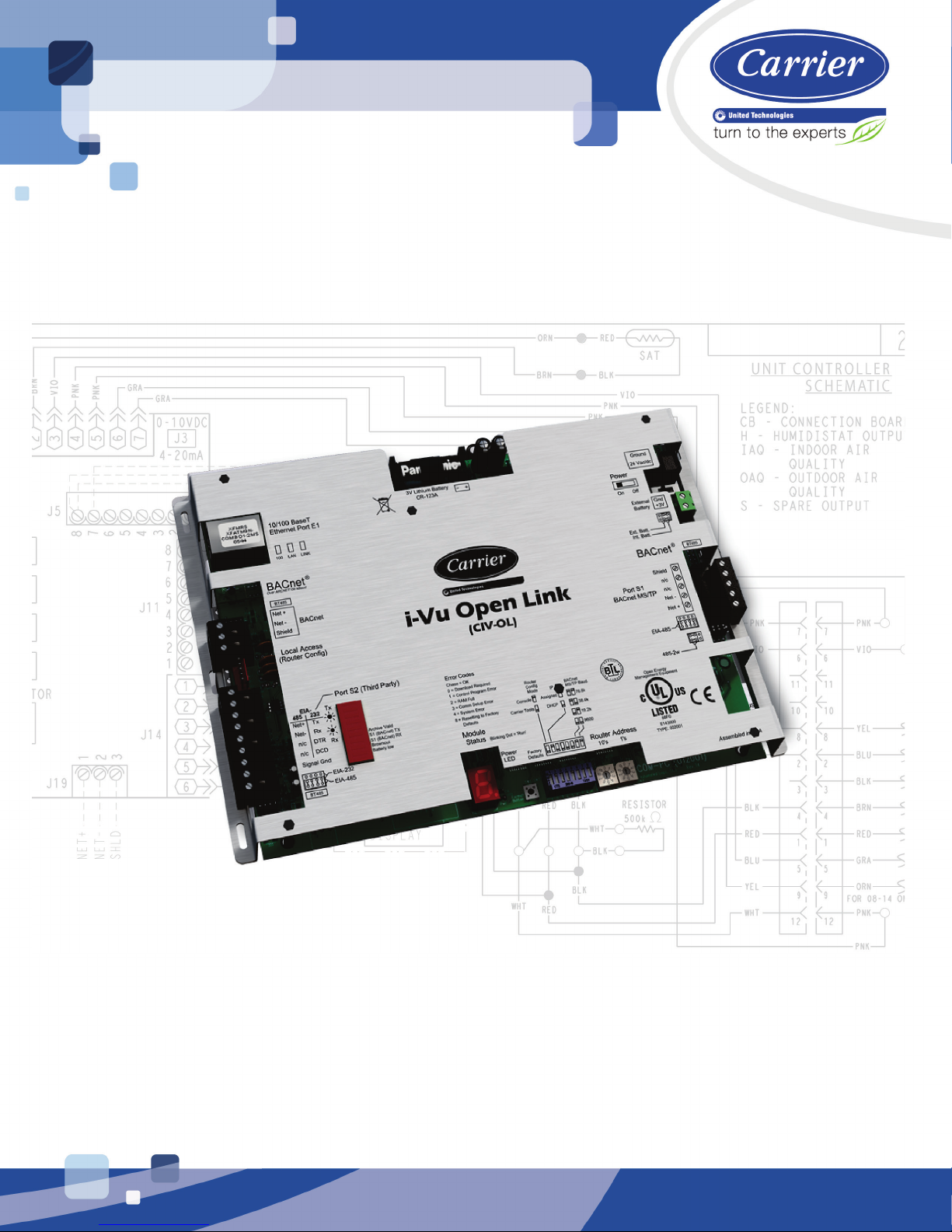
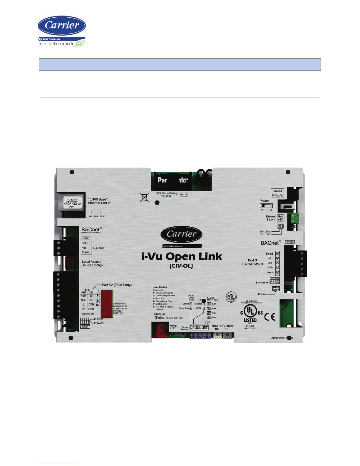
What is a i-Vu® Open Link?
The i-Vu® Open Link is a BACnet device router that acts as a gateway between the BACnet IP network and a
BACnet MS/TP network. The i-Vu® Open Link increases the capacity of an Open system, allowing individual MS/TP
networks (with up to 60 Open controllers each) to be connected via a common BACnet/IP backbone.
The i-Vu® Open Link can also integrate third-party equipment, supporting BACnet MS/TP, BACnet/IP, Modbus
RTU, Modbus/IP, and LON FT-10 protocols. The i-Vu® Open Link has one EIA-485 port for connecting to the Open
or third
-party MS/TP bus, and one jumper-configurable EIA-232/EIA-485 port for connecting to a Modbus or
LonWorks network. It also has one 10/100 Base-T Ethernet port for connecting to the building LAN and integrating
to third-party IP control networks.
Introduction
Page 6

Introduction
i-Vu Open Link Carrier Proprietary and Confidential CARRIER CORPORATION ©2017
Installation and Start-up Guide All rights reserved
2
Specifications
Driver
drv_ivuopenlink_std_x-xxx-xxx
Maximum number of Open
controllers supported
60
Maximum number of control
programs
199
Maximum number of thirdparty integration points
using Snap*†
500
* Depends on available memory
† BACnet third
-party integration points are not counted.
Power
24 Vac ±10%, 50–60 Hz
24 VA power consumption
26 Vdc (25 V min, 30 V max)
Single Class 2 source only, 100 VA or less
Port E1 (10/100 BaseT
Ethernet)
For Ethernet LAN, BACnet IP, and Modbus TCP/IP communication at 10 or 100 Mbps,
half duplex
Both Assigned (default) and DHCP IP addressing are supported and DIP switch
selectable
Port S1 (BACnet MS/TP)
For communication with the controller network using BACnet MS/TP at 9600 bps, 19.2
kbps, 38.4 kbps, or 76.8 kbps (DIP switch selectable). Default is 76.8k bps.
BACnet
For communication with the controller network using ARC156 (156 kbps)
Port S2
Configurable EIA-485/EIA-232 port for third-party network connections, including:
• Modbus (RTU) - 9600 bps, 19.2 kbps, 38. 4 kbps
• LonWorks (requires SLTA-10 adapter)
Local Access (Router Config)
For system start-up and troubleshooting using Field Assistant or an Equipment Touch
device
Real time clock
Battery-backed real-time clock keeps track of time in event of power failure
Battery
10-year Lithium CR123A battery ensures the following data is retained for a maximum
of 720 hours during power outages:
• Time
• Graphics
• Control programs
• Editable properties
• Schedules
• Trends
To conserve battery life, you can set the driver to turn off battery backup after a
specified number of days and depend on the archive function to restore data when the
power returns.
A low battery is indicated by the Battery Low LED or a low battery alarm in the i-Vu® or
Field Assistant application, a touchscreen device, and Field Assistant.
Page 7

Introduction
i-Vu Open Link Carrier Proprietary and Confidential CARRIER CORPORATION ©2017
Installation and Start-up Guide All rights reserved
3
Protection
Incoming power and network connections are protected by non
-replaceable internal
solid-state polyswitches that reset themselves when the condition that causes a fault
returns to normal.
The power and networ
k connections are also protected against transient excess
voltage/surge events lasting no more than 10 msec.
Status indicators
LED status indicators for Port S1 and S2 communication, Ethernet Port E1
communication, and low battery status. Seven segment status display for running,
error, power status, archive valid, and brownout.
Environmental operating
range
-20 to 140°F (-29 to 60°C), 10–90% relative humidity, non-condensing
Storage temperature range
-24 to 140°F (-30 to 60°C), 0 to 90% relative humidity, non-condensing
Physical
Rugged aluminum cover, removable screw-type terminal blocks
Overall dimensions
A:
B:
7-1/2 in. (19.1 cm)
11-5/16 in. (28.7 cm)
Mounting dimensions
C:
D:
E:
F:
5 in. (12.7 cm)
10-7/8 in. (27.6 cm)
1-1/4 in. (3.2 cm)
1/4 in. (.6 cm)
Mount with 6-32 by 1/2 in. mounting screws
Depth
1-1/4 in. (3.2 cm)
Weight
1.4 lbs (0.64 kg)
BACnet support
Conforms to the BACnet Building Controller (B-BC) Standard Device Profile as defined
in ANSI/ASHRAE Standard 135-2012 (BACnet) Annex L, Protocol Revision 9
Listed by
UL916 (Canadian Std C22.2 No. 205-M1983, CE, FCC Part 15 - Subpart B - Class A
Safety considerations
WARNING Disconnect electrical power to the i-Vu® Open Link before wiring it. Failure to follow this warning
could cause electrical shock, personal injury, or damage to the controller.
Page 8

Installing the i-Vu® Open Link
i-Vu Open Link Carrier Proprietary and Confidential CARRIER CORPORATION ©2017
Installation and Start-up Guide All rights reserved
4
1 Mount the i-Vu® Open Link (page 4).
2 Wire for power (page 5).
3 Set the i-Vu® Open Link's address and IP address (page 5).
4 Wire for communications (page 9).
5 Communicate through the Local Access port (page 12).
6 Configure BACnet Device Instance and network number (page 15).
Mounting the i-Vu® Open Link
WARNING
When you handle the i-Vu® Open Link:
• Do not contaminate the printed circuit board with fingerprints, moisture, or any foreign material.
• Do not touch components or leads.
• Handle the board by its edges.
• Isolate from high voltage or electrostatic discharge.
• Ensure that you are properly grounded.
Screw the i-Vu® Open Link into an enclosed panel using the mounting slots on the cover plate. Leave about 2 in.
(5 cm) on each side of the controller for wiring.
Installing the i-Vu® Open Link
Page 9

Installing the i-Vu® Open Link
i-Vu Open Link Carrier Proprietary and Confidential CARRIER CORPORATION ©2017
Installation and Start-up Guide All rights reserved
5
Wiring the i-Vu® Open Link for power
WARNING Do not apply line voltage (mains voltage) to the controller's ports and terminals.
CAUTIONS
• The i-Vu® Open Link is powered by a Class 2 power source. Take appropriate isolation measures when
mounting it in a control panel where non-Class 2 circuits are present.
• Carrier controllers can share a power supply as long as you:
• Maintain the same polarity.
○ Use the power supply only for Carrier controllers.
To wire for power
1 Make sure the i-Vu® Open Link’s power switch is in the OFF position to prevent it from powering up before
you can verify the correct voltage.
2 Remove power from the power supply.
3 Pull the screw terminal connector from the controller's power terminals labeled 24 Vac/Vdc and Ground.
4 Connect the transformer wires to the screw terminal connector.
5 Apply power to the power supply.
6 Measure the voltage at the i-Vu® Open Link’s power input terminals to verify that the voltage is within the
operating range of 21.6 – 26.4 Vac or 23.4 - 28.6 Vdc.
7 Insert the screw terminal connector into the i-Vu® Open Link's power terminals.
8 Turn on the i-Vu® Open Link's power.
9 Verify that the Run LED (a dot in the lower right corner of the Module Status LED) begins blinking. The Module
Status LED will display 8 for about 5 seconds and then reverts to 0, until controllers have been found and
downloaded. There is a chase pattern when the controller is running with no errors.
Addressing the i-Vu® Open Link
i-Vu Open Control hardware, when used in conjunction with i-Vu Open routers (i-Vu® Open Link and i-Vu® Open
Router), has a convenient feature of automatic addressing. To address the i-Vu® Open Link for third-party
integration, using i-Vu® or Field Assistant, go to Driver Properties > Protocols > Properties tab. Refer to the
appropriate protocol Integration Guide for further details.
Page 10

Installing the i-Vu® Open Link
i-Vu Open Link Carrier Proprietary and Confidential CARRIER CORPORATION ©2017
Installation and Start-up Guide All rights reserved
6
The i-Vu® Open Link needs two addresses, one for the Open network and one for the IP Network.
The i-Vu® Open Link
needs...
That is unique
on the...
Notes
A router address
Open network
You set the i-Vu® Open Link address on the controller's
rotary switches. (1 - 99)
NOTE The i-Vu® Open Link address is also used to autogenerate the BACnet device instance/name for the router
and the MS/TP network number for the connected Open
network. See Configuring BACnet device instance and
network number.
An IP address
IP Network
Set the IP Addr DIP switch to choose one of the following:
• DHCP — to obtain an IP address from a DHCP server
If there is no DHCP server, the following
are the default
IP settings:
○ 192.168.168.xx, where xx = router address
○ subnet mask = 255.255.255.0
○ default gateway = 192.168.168.254
• Assigned
— a
custom IP address
To set the i-Vu® Open Link address on the Open network
CAUTION The i-Vu® Open Link address must be unique on the IP and Open network.
1 If wired for power, turn off the controller's power.
The controller only reads the rotary switch positions during power up or upon reset.
2 Use the rotary switches to set the address. Set the Tens (10's) switch to the tens digit of the address, and set
the Ones (1's) switch to the ones digit. Valid addresses are 1 - 99.
EXAMPLE If the controller’s address is 25, point the arrow on the Tens (10's) switch to 2 and the arrow on
the Ones (1's) switch to 5.
10's 1's
1
3
4
5
2
7
8
9
6
0
1
3
4
5
2
7
8
9
6
0
3 Turn on the i-Vu® Open Link's power.
CAUTION The factory default setting is 00 and must be changed to successfully install your i-Vu® Open Link.
Page 11

Installing the i-Vu® Open Link
i-Vu Open Link Carrier Proprietary and Confidential CARRIER CORPORATION ©2017
Installation and Start-up Guide All rights reserved
7
To choose an IP addressing scheme
Carefully plan your addressing scheme to avoid duplicate IP addresses.
• If there is a DHCP server on the network, and, if you have a single i-Vu® Open Link or multiple i-Vu® Open
Links that exist on the SAME subnet, use DHCP addressing. Skip to the section To obtain an IP address using
DHCP (page 7).
• If you have multiple i-Vu® Open Links that reside on different subnets, you cannot use DHCP addressing.
Instead, give each i-Vu® Open Link an assigned IP address. Skip to the section To assign a custom IP
address (page 7).
NOTE This network configuration also requires that you configure IP Broadcast Management Devices
(BBMDs). See To set up BACnet Broadcast Management Devices. (page 17)
To obtain an IP address using DHCP
1 Turn the i-Vu® Open Link's power off.
2 Set the IP Addr DIP switch DHCP to On.
3 Turn the i-Vu® Open Link's power on. The DHCP server assigns an IP address to the i-Vu® Open Link.
CAUTION If the DHCP server is not found, the following default IP address settings will be used:
• IP address = 192.168.168.xx, where xx = i-Vu® Open Link address (rotary switch settings)
• Subnet Mask = 255.255.255.0
• Default Gateway = 192.168.168.254
To assign a custom IP address
1 Obtain the IP address, subnet mask, and default gateway address for the controller from the facility network
administrator.
2 Turn the i-Vu® Open Link's power off.
3 Set the i-Vu® Open Link's IP Addr DIP switch Assigned to On.
4 Configure the i-Vu® Open Link by setting the Router Config Mode DIP switch Console to On using a terminal
program such as PuTTY or Hyperterminal.
5 Turn the i-Vu® Open Link's power on.
PREREQUISITES
• A computer with a USB port
• A USB Link cable — See To communicate through the Local Access port with a USB Link (page 12)
Page 12

Installing the i-Vu® Open Link
i-Vu Open Link Carrier Proprietary and Confidential CARRIER CORPORATION ©2017
Installation and Start-up Guide All rights reserved
8
CAUTION If multiple controllers share power but polarity was not maintained when they were wired, the
difference between the controller's ground and the computer's AC power ground could damage the USB Link and
the controller. If you are not sure of the wiring polarity, use a USB isolator between the computer and the USB
Link. Purchase a USB isolator online from a third-party manufacturer.
Using PuTTY
1 Download and install PuTTY from the PuTTY website
(http://www.chiark.greenend.org.uk/~sgtatham/putty/download.html).
2 Connect the laptop to the local access port of the controller, ZS sensor, or an SPT sensor using the USB Link
cable(s).
NOTE If using a USB isolator, plug the isolator into your computer's USB port, and then plug the USB Link
cable into the isolator.
3 To change a router's IP address, subnet mask, or default gateway, set its IP Address DIP switch to Assigned.
4 Start PuTTY.
5 Under Category > Connection, select Serial.
6 Under Options controlling local serial lines, enter the following settings:
Field
Value
Serial line to connect to
Replace X with the computer's port number that the USB Link Kit cable is
connected to.
NOTE To find the port number, select Start > Control Panel > System >
Device Manager > Ports (Com & LPT). The COM port number is beside
Silicon Labs CP210x USB to UART Bridge.
Speed (baud)
115200
Data Bits
8
Stop Bits
1
Parity
None
Flow Control
None
Page 13

Installing the i-Vu® Open Link
i-Vu Open Link Carrier Proprietary and Confidential CARRIER CORPORATION ©2017
Installation and Start-up Guide All rights reserved
9
7 Click Open. A window similar to the one below appears.
8 Do one of the following:
○ To change a property value:
a. Type the number of the property, then press Enter.
b. Type the new value, then press Enter.
○ To take an action, type number of the action, then press Enter.
9 If you changed a value, type
1, then press
Enter to restart the controller.
10 Close PuTTY.
11 Verify that you can communicate with the i-Vu® Open Link by issuing a PING command to the IP address
specified in step 12.
NOTE Your computer must be on the same subnet as the i-Vu® Open Link for the PING command to work.
12 When finished, set the i-Vu® Open Link's Router Config Mode DIP switch to OFF to restore normal
functionality to the Local Access port.
13 Cycle the i-Vu® Open Link's power to accept the Router Config Mode changes.
Wiring for communications
The i-Vu® Open Link has multiple ports. See table below for port descriptions.
Port
Protocol
Port
type(s)
Baud rate(s)
Use for
Ethernet
Port E1
BACnet/IP
Ethernet
10 Mbps
100 Mbps
LAN connection
BACnet
ARC156
EIA-485 (2wire)
156 kbps
Open network connection
S1 BACnet MS/TP
EIA-485
(2-wire)
DIP Switch selectable:
• 9600 bps
• 19.2 kbps
• 38.4 kbps
• 76.8 kbps (default)
Open network connection
Page 14

Installing the i-Vu® Open Link
i-Vu Open Link Carrier Proprietary and Confidential CARRIER CORPORATION ©2017
Installation and Start-up Guide All rights reserved
10
Port Protocol
Port
type(s)
Baud rate(s)
Use for
S2* Modbus
LonWorks
EIA-485
EIA-232
DIP switch selectable
Third-party communication
Local
Access
N/A
Rnet
115.2 kbps
• Router configuration
• System start-up and
troubleshooting
* The Router Config Mode DIP switch Console must be Off (down position) to use Port S2.
Ethernet, BACnet MS/TP, and ARC156 wiring specifications
For...
Use...
Maximum Length
Ethernet
CAT5e or higher Ethernet cable
328 feet (100 meters)
BACnet
MS/TP*
BACnet
ARC156*
22 or 24 AWG, low-capacitance, twisted,
stranded, shielded copper wire
2000 feet (610 meters)
*
For details see the Open Controller Network Wiring Guide.
WARNING Do not apply line voltage (mains voltage) to the controller's ports and terminals.
To connect the i-Vu® Open Link to the Ethernet
Connect an Ethernet cable to the Ethernet Port E1.
To wire the BACnet MS/TP network
1 Turn the i-Vu® Open Link's power off.
2 Check the communications wiring for shorts and grounds.
3 Verify that the Port S1 jumpers are set to 485-2w.
4 Set the MS/TP baud rate DIP switches 7 and 8 to match the baud rate of the Open network. The default is
76.8k.
5 Connect the i-Vu® Open Link's Port S1 to the Open MS/TP network. Use the same polarity throughout the
network segment.
Page 15

Installing the i-Vu® Open Link
i-Vu Open Link Carrier Proprietary and Confidential CARRIER CORPORATION ©2017
Installation and Start-up Guide All rights reserved
11
Wire the Port S1 terminal...
To this Open controller terminal...
Shield (Pin 1)
Shield
Net- (Pin 4)
Net
-
Net+ (Pin 5)
Net+
6 Turn the i-Vu® Open Link's power on.
To wire to a BACnet ARC156 network
1 Turn off
the i-Vu® Open Link's power.
2 Check t
he communications wiring for shorts and grounds.
3 Connect the communications wiring to the controller’s screw terminals labeled Net +, Net -, and Shield on the
BACnet port.
NOTE Use the same polarity throughout the network segment.
4 If the i-Vu® Open Link is at either end of a network segment, connect a BT485 to the i-Vu® Open Link.
5 Turn on the i-Vu® Open Link's power.
6 Verify communication with the network by viewing a Module Status report in the i-Vu® or Field Assistant
interface.
To wire Modbus or LonWorks devices
1 Turn off the i-Vu® Open Link's power.
2 Check the communications wiring for shorts and grounds.
3 Set the Router Config Mode DIP switch Console to Off (down position).
4 Wire the i-Vu® Open Link's Port S2 to the third-party device, then set the S2 jumper. See table and notes
below.
5 Turn on the i-Vu® Open Link's power.
For...
Use i-Vu® Open Link
port...
Wire Carrier
terminal...
...to third-party
device terminal
Set the port's jumper(s)
on i-Vu® Open Link
EIA-232
S2
TX
Rx
Signal Ground
Rx
Tx
Gnd
EIA-232
EIA-485,
2-wire
S2
Net+
Net- + -
EIA-485
2-wire
Page 16

Installing the i-Vu® Open Link
i-Vu Open Link Carrier Proprietary and Confidential CARRIER CORPORATION ©2017
Installation and Start-up Guide All rights reserved
12
NOTES
• If you cannot determine the media type or connections of the third-party device, contact your third-party
representative.
• Use the same polarity throughout the network segment.
• Repeaters are required for more than 31 devices. See your third-party device manufacturer's
recommendations.
• To reduce communication and data errors, terminate each end of an EIA-485 network with a resistor whose
value equals the network's characteristic impedance. Some third-party manufacturers provide a built-in
resistor that you enable or disable with a jumper. Make sure that only devices at the end of a network have
termination enabled.
EXAMPLE If an EIA-485 2-wire network's characteristic impedance is 120 Ohms, terminate one pair by
placing a 120 Ohm resistor across the Net+ and NET- connectors of the i-Vu® Open Link. Terminate the other
pair by placing a 120 Ohm resistor across the + and - connectors of the furthest third-party controller.
• A solid receive light on the i-Vu® Open Link indicates a wiring or polarity problem.
Communicating through the Local Access port with a USB Link
Using a computer and a USB Link, you can communicate locally with the i-Vu® Open Link to download or to
troubleshoot.
CAUTIONS
• Maintain polarity when controllers share power.
• Failure to maintain polarity while using the USB Link on a computer that is grounded via its AC adapter may
damage the USB Link and the controller.
• If multiple controllers share power but polarity was not maintained when they were wired, the difference
between the controller's ground and the computer's AC power ground could damage the USB Link and the
controller. If you are not sure of the wiring polarity, use a USB isolator between the computer and the USB
Link. Purchase a USB isolator online from a third-party manufacturer. Plug the isolator into your computer's
USB port, and then plug the USB Link cable into the isolator.
PREREQUISITES
• For the i-Vu® or Field Assistant application to communicate with the controller, the controller must have been
downloaded with at least its driver.
• Laptop with USB port
• USB Link (Part #USB-L)
Page 17

Installing the i-Vu® Open Link
i-Vu Open Link Carrier Proprietary and Confidential CARRIER CORPORATION ©2017
Installation and Start-up Guide All rights reserved
13
Using a USB Link
1 If your computer does not already have the USB Link driver installed, install it before you connect the USB
Link to your computer.
NOTE The driver is installed with the i-Vu® or Field Assistant v5 or later system. But if needed, you can get
the latest driver from http://www.silabs.com/products/mcu/Pages/USBtoUARTBridgeVCPDrivers.aspx.
2 Connect the laptop to the Local Access port of the controller using the USB Link cable(s).
NOTE If using a USB isolator, plug the isolator into your computer's USB port, and then plug the USB Link
cable into the isolator.
3 Set the controller's Router Config Mode DIP switch.
To communicate in...
Set switch to...
The i-Vu® or Field Assistant application
Off
PuTTY or HyperTerminal
NOTE See To communicating using PuTTY (page 13)
On
4 Turn the controller's power off, then on again.
To communicate using PuTTY
You can connect a computer to a controller's Local Access port and use PuTTY, a free open source terminal
emulation program, to:
• Set the baud rate for Port S1 on the i-Vu® Open Link
• Set controller properties, such as IP address and network information
• Retrieve a Modstat
PREREQUISITES
• A computer with a USB port
• A USB Link cable
NOTE The USB Link driver is installed with an i-Vu® or Field Assistant v5 or later system. But if needed, you
can get the latest driver from
http://www.silabs.com/products/mcu/Pages/USBtoUARTBridgeVCPDrivers.aspx. Install the driver before
you connect the USB Link to your computer.
Page 18

Installing the i-Vu® Open Link
i-Vu Open Link Carrier Proprietary and Confidential CARRIER CORPORATION ©2017
Installation and Start-up Guide All rights reserved
14
CAUTION If multiple controllers share power but polarity was not maintained when they were wired, the
difference between the controller's ground and the computer's AC power ground could damage the USB Link and
the controller. If you are not sure of the wiring polarity, use a USB isolator between the computer and the USB
Link. Purchase a USB isolator online from a third-party manufacturer.
Using PuTTY
1 Download and install PuTTY from the PuTTY website
(http://www.chiark.greenend.org.uk/~sgtatham/putty/download.html).
2 Connect the laptop to the local access port of the controller, ZS sensor, or an SPT sensor using the USB Link
cable(s).
NOTE If using a USB isolator, plug the isolator into your computer's USB port, and then plug the USB Link
cable into the isolator.
3 To change a router's IP address, subnet mask, or default gateway, set its IP Address DIP switch to Assigned.
4 Start PuTTY.
5 Under Category > Connection, select Serial.
6 Under Options controlling local serial lines, enter the following settings:
Field
Value
Serial line to connect to
Replace X with the computer's port number that the USB Link Kit cable is
connected to.
NOTE To find the port number, select Start > Control Panel > System >
Device Manager > Ports (Com & LPT). The COM port number is beside
Silicon Labs CP210x USB to UART Bridge.
Speed (baud)
115200
Data Bits
8
Stop Bits
1
Parity
None
Flow Control
None
Page 19

Installing the i-Vu® Open Link
i-Vu Open Link Carrier Proprietary and Confidential CARRIER CORPORATION ©2017
Installation and Start-up Guide All rights reserved
15
7 Click Open. A window similar to the one below appears.
8 Do one of the following:
○ To change a property value:
a. Type the number of the property, then press Enter.
b. Type the new value, then press Enter.
○
To take an action, type number of the action, then press Enter.
9
If you changed a value, type
1, then press Enter
to restart the controller.
10 Close PuTTY.
Configuring BACnet Device Instance and network number
All BACnet Open controllers must have a unique Device Instance and Name. These BACnet addresses are
automatically generated and usually do not require modification. However, sometimes you need to override the
automatic addressing assignments.
Autogenerated addressing scheme:
The i-Vu® Open Link's rotary address setting determines the automatic BACnet addressing scheme for the
connected Open network.
Legend
16 = Carrier's BACnet Vendor ID
xx = i-Vu® Open Link's rotary switch address (BACnet Device Instance address)
yy = Open controller's rotary switch address (MS/TP MAC address)
For the i-Vu® Open Link:
• BACnet Device Instance Number = 1600xx
• BACnet Device Instance Name = device1600xx
• BACnet IP Network Number = 1600
• BACnet MS/TP Network Number = 161xx
• BACnet ARC156 Network Number = 163xx
• Port S1 MS/TP MAC Address = 0 (fixed)
Page 20

Installing the i-Vu® Open Link
i-Vu Open Link Carrier Proprietary and Confidential CARRIER CORPORATION ©2017
Installation and Start-up Guide All rights reserved
16
For the Open controllers connected to the i-Vu® Open Link
• BACnet MS/TP Device Instance Number = 161xxyy
• BACnet ARC156 Device Instance Number = 163xxyy
• BACnet MS/TP Device Instance Name = device161xxyy
• BACnet ARC156 Device Instance Name = device163xxyy
• BACnet MS/TP or ARC156 MAC Address = yy
• BACnet MS/TP Network Number = 161xx (learned from the router, defaults to 16101 if no i-Vu® Open Link is
operating)
If the BACnet automatic settings need to be changed, launch the
Router Configuration utility using a terminal
program. See To assign a custom IP address for instructions on connecting to and using a terminal program.
To change the BACnet settings:
1 Enter the BACnet selection# from the menu. Type the new setting and click Enter. The new setting will appear
on the Router Configuration screen.
2 Cycle power to the router for the new settings to take effect.
NOTE If the BACnet MS/TP or ARC156 network number of the router is assigned and not auto-generated,
and the Open controllers connected to that router are set such that their BACnet settings are auto-generated,
then the Open controller BACnet settings will be auto-generated based on the assigned MS/TP network
number in the router:
Example A router's BACnet MS/TP or ARC156 network has been assigned to 200.
If the connected Open controllers are using autogenerate, then their settings will be:
BACnet MS/TP Network Number = 200
BACnet Device Instance Number = 200yy
BACnet Device Instance Name = device200yy
BACnet MS/TP MAC Address = yy
Page 21

Installing the i-Vu® Open Link
i-Vu Open Link Carrier Proprietary and Confidential CARRIER CORPORATION ©2017
Installation and Start-up Guide All rights reserved
17
To set up BACnet Broadcast Management Devices (BBMDs)
If your system has multiple routers that reside on different IP subnets, you must set up one router on each IP
subnet as a BACnet/IP Broadcast Management Device (BBMD).
Every subnet with a router must have a BBMD configured in order for broadcasts from controllers on that subnet
to reach the rest of the routers on the network.
NOTES
• The i-Vu® Standard or Plus application - If the i-Vu® web server is on a separate subnet than the rest of the
routers, the internal router must be assigned an IP address and configured as a BBMD.
• The i-Vu® Pro application - If the i-Vu® Pro server is on a separate subnet than the rest of the routers, you
must register it as a foreign device.
Use the BBMD Configuration Tool to:
• Define the Broadcast Distribution Table (BDT) in each BBMD
• Enable an i-Vu® Control System to find routers that are on different subnets
• Allow controllers on one subnet to communicate with controllers on other subnets
• Enable the i-Vu® application to see, upload, or configure controllers on different subnets
Page 22

Installing the i-Vu® Open Link
i-Vu Open Link Carrier Proprietary and Confidential CARRIER CORPORATION ©2017
Installation and Start-up Guide All rights reserved
18
To set up BBMDs using the BBMD Configuration Tool
1 Assign an IP address, subnet mask, and default gateway for each i-Vu® Open Link on the IP network. See
Addressing the i-Vu® Open Link (page 5).
2 Acquire the BBMD Configuration Tool from the Tech Tools DVD or from the Carrier Control Systems Support
Site http://www.hvacpartners.com/. This is a stand-alone executable file and no installation is necessary.
3 Make a list of the IP addresses for each router that will function as a BBMD in your system.
In the above illustration, the i-Vu® Open Link, address 172.18.1.2, must be configured as a BBMD for the
172.18 subnet, while the i-Vu® Open Link, address 172.16.1.15, must be configured as a BBMD for the
172.16 subnet.
CAUTIONS
○ Define only one BBMD per subnet. Multiple BBMD's on an IP subnet disrupt network communications.
○ Unless explicitly modified, the UDP Port for BACnet/IP is 0xBAC0 (47808). Do not change this parameter
unless you made a change in the router.
4 In a text editor such as Notepad, create a list of the routers that will be BBMD's. List each IP address on a
separate line. (Maximum of 50 IP addresses per file)
5 Save the file to your folder of choice with a .bdt extension instead of .txt.
NOTE ".bdt" is a Broadcast Distribution Table file.
6 Open the BBMD Configuration Tool.
7 In the IP Address or Host Name field, type the IP address of the router that functions as the BBMD (BACnet
Broadcast Management Device) for its subnet.
8 To check if the router has an existing BBMD table, click the Broadcast Distribution Table Read button.
9 If the Broadcast Distribution Table contains IP addresses that are not in your .bdt file, verify that they are
valid BBMD's and, if so, add them to your .bdt file.
NOTES
○ The BDT's in each BBMD should be identical. Repeat this entire process whenever a BBMD is added.
○ If needed, disable the checkbox next to Show Broadcast to limit the amount of scrolling text that is
displayed.
10 Click the Broadcast Distribution Table Browse button and select the .bdt file that you made in step 4.
11 Verify that the appropriate IP address is still in the IP Address or Host Name field.
12 Click the Broadcast Distribution Table Write button.
13 Click Read again to verify that the new .bdt file was written to the router. See example below.
Page 23

Installing the i-Vu® Open Link
i-Vu Open Link Carrier Proprietary and Confidential CARRIER CORPORATION ©2017
Installation and Start-up Guide All rights reserved
19
NOTE If you have a large BDT, you may have to re-size the BBMD Configuration Tool window to see the
Broadcast Distribution Table.
14 Using the next IP address in the .bdt file, repeat steps 7 through 14 until every file has been updated.
NOTE To clear the BBMD entries from a router, follow the steps above using an empty (blank) .bdt file. A
cleared BBMD table contains just the router’s IP address without entries in the BBMD table, as shown below.
Page 24

Configuring i-Vu® Open Link Driver Properties
i-Vu Open Link Carrier Proprietary and Confidential CARRIER CORPORATION ©2017
Installation and Start-up Guide All rights reserved
20
After you find and upload the i-Vu® Open Link in the i-Vu® or Field Assistant interface, you may want to customize
the i-Vu® Open Link's settings for your applications. You can change settings on the Driver Properties page.
1 In the i-Vu® or Field Assistant interface, right-click the i-Vu® Open Link in the navigation tree and select
Driver Properties.
2 Adjust the driver as desired.
Driver
On the Driver page, you can change the following properties:
• Backup battery conservation settings. See table below.
• Module clock synchronization and failure. See table below.
• Network Input microblock communication properties.
Backup Battery
Turn off internal backup
battery after ___ days to
conserve battery life (shutoff
date/time)
How long backup battery should run after power loss.
TIP Downloading activates the battery backup. To conserve battery life
when you know the i-Vu® Open Link will be without power for an extended period
after downloading (for example, during shipment):
1
Verify the Archive Valid
LED is lit, then set this field to 0.
2 After you install the i-Vu® Open Link and apply power, enter a number
greater than 0.
BACview Control
Keypad inactivity timeout
(minutes)
Log out the user (if a user-level password is required), turn off the backlight, and
display the standby screen after this period of inactivity.
Keypad user
-level password
Numeric password user must enter to access system through a BACview®
device.
TouchScreen Control
TouchScreen Schedule Edit
Enable
Check this field to allow a user to edit this controller's schedules from an
Equipment Touch's Schedules screen.
Module Clock
Clock Fail Date and Time
Date and time the control program uses when controller's real-time clock is
invalid.
TIP Use an occupied date and time (such as a Tuesday at 10 a.m.) so the
equipment does not operate in unoccupied mode if the controller loses power
during occupancy.
Configuring i-Vu® Open Link Driver Properties
Page 25

Configuring i-Vu® Open Link Driver Properties
i-Vu Open Link Carrier Proprietary and Confidential CARRIER CORPORATION ©2017
Installation and Start-up Guide All rights reserved
21
Time Synch Sensitivity
(seconds)
When the controller receives a time sync request, if the difference between the
controller's time and the time sync's time is greater than this field's value, the
controller's time is immediately changed. If the difference is less than this field's
value, the controller's time is slowly adjusted until the time is correct.
BACnet COV Throttling
Enable COV Throttling
Under normal circumstances, COV Throttling should be enabled to prevent
excessive network traffic if an object's COV Increment is set too low. See
EXCEPTION below.
When enabled, if an object generates excessive COV broadcasts (5 updates in 3
seconds), the driver automatically throttles the broadcasts to 1 per second. Also,
if the object's value updates excessively for 30 seconds, an alarm is sent to the iVu® or Field Assistant application listing all objects that are updating
excessively. A Return-to-normal alarm is sent only after all objects have stopped
updating excessively.
EXCEPTION: In rare circumstances, such as process control, a subscribing object
may require COV updates more frequently than once per second. For these
situations, clear this checkbox, but make sure that your network can support the
increased traffic. You will also need to disable the Excessive COV alarms under
the driver's Common Alarms.
Device
On the Driver
> Device
page, you can change the following properties:
• BACnet device object properties for the i-Vu® Open Link
• i-Vu® Open Link communication
Configuration
NOTE The three APDU fields refer to all networks over which the i-Vu® Open
Link communicates.
Max Masters and Max Info
Frames
Max Masters - defines the highest MS/TP Master MAC address on the MS/TP
network.
For example, if there are 3 master nodes on an MS/TP network, and their MAC
addresses are 1, 8, and 16, then Max Masters would be set to 16 (since this is
the highest MS/TP MAC address on the network).
This property optimizes MS/TP network communications by preventing token
passes and “poll for master” requests to non-existent Master nodes.
In the above example, MAC address 16 knows to pass the token back to MAC
address 1, instead of counting up to MAC address 127. Each MS/TP master
node on the network must have their Max Masters set to this same value. The
default is 127.
Max Info Frames - defines the maximum number of responses that will be sent
when the i-Vu® Open Link receives the token. Any positive integer is a valid
number. The default is 10 and should be ideal for the majority of applications. In
cases where the i-Vu® Open Link is the target of many requests, this number
could be increased as high as 100 or 200.
Page 26

Configuring i-Vu® Open Link Driver Properties
i-Vu Open Link Carrier Proprietary and Confidential CARRIER CORPORATION ©2017
Installation and Start-up Guide All rights reserved
22
Notification Classes
Alarms in the i-Vu® or Field Assistant application use Notification Class #1. A BACnet alarm's Notification Class
defines:
• Alarm priority for Alarm, Fault, and Return to Normal states
• Options for BACnet alarm acknowledgment
• Where alarms should be sent (recipients)
Priorities
NOTE BACnet defines the following Network message priorities for Alarms and
Events.
Priority range
Network message priority
00–63
Life Safety
64–127
Critical Equipment
128–191
Urgent
192–255
Normal
Priority of Off-Normal
BACnet priority for Alarms.
Priority of Fault
BACnet priority for Fault messages.
Priority of Normal
BACnet priority for Return-to-normal messages.
Ack Required for Off-Normal,
Fault, and Normal
Specifies whether alarms associated with this Notification Class require a BACnet
Acknowledgment for Off-Normal, Fault, or Normal alarms.
TIP You can require operator acknowledgment for an Alarm or Return-tonormal message (stored in the i-Vu® or Field Assistant database). In the i-Vu® or
Field Assistant interface on the Alarm > Enable/Disable tab, change the
acknowledgment settings for an alarm source or an alarm category.
Recipient List
Recipients
The first row in this list is the i-Vu® or Field Assistant application. Do not delete
this row. Click Add
if you want other BACnet devices to receive alarms associated
with this Notification Class.
Recipient Description
Name that
appears in the
Recipients
table.
Recipient Type
Use Address (static binding) for either of the following:
• Third-party BACnet device recipients that do not support dynamic binding
• When you want alarms to be broadcast (you must uncheck Issue Confirmed
Notifications). This use is rare.
Days and times
The days and times during which the recipient will receive alarms.
Recipient Device Object
Identifier
Type the Device Instance from the network administrator for third-party devices)
in the # field.
Process Identifier
Change for third-party devices that use a BACnet Process Identifier other than 1.
The i-Vu® or Field Assistant application processes alarms for any 32-bit Process
Identifier.
Page 27

Configuring i-Vu® Open Link Driver Properties
i-Vu Open Link Carrier Proprietary and Confidential CARRIER CORPORATION ©2017
Installation and Start-up Guide All rights reserved
23
Issue Confirmed
Notifications
Select to have a device continue sendin
g an alarm message until it receives
delivery confirmation from the recipient.
Transitions to Send
Uncheck the types of alarms you do not want the recipient to get.
Calendars
Calendars are provided in the driver for BACnet compatibility only. Instead,
use the
Schedules feature in the i-Vu®
or Field Assistant interface.
Common and Specific Alarms
On these pages, you can enable/disable, change BACnet alarm properties, or set delays for the following BACnet
alarms:
Common alarms:
Specific Alarms:
• All Programs Stopped
• Control Program
• Duplicate Address
• Excessive COV
• Locked I/O
• Module Halted
• Program Stopped
• Dead Module Timeout
• Low Battery Alarm
NOTE To set up alarm actions for controller-generated alarms, see Set up alarm actions in i-Vu® Help.
Controller-generated Alarm
Description
Short message shown on i-Vu®'s Alarm page or in an alarm action when this
type of alarm is generated.
Events
Enable
Clear these checkboxes to disable Alarm or Return to normal messages of this
type from this controller.
Notification Class
Do not change this field.
Page 28

Configuring i-Vu® Open Link Driver Properties
i-Vu Open Link Carrier Proprietary and Confidential CARRIER CORPORATION ©2017
Installation and Start-up Guide All rights reserved
24
BACnet router properties
On the BACnet router properties page, you can change the following properties:
• BACnet routing settings
• Color and prime variable caching settings
BACnet Router Options
Ignore all Reject-Message-toNetwork, Reason=1
messages
Clear to delete and redownload a router if a network's router indicates that the
network is no longer present (reason=1).
Select to continue routing messages to a network even if its router indicates that
the network is no longer present.
Color/Prime Variable
Caching
Disable Color Cache
Clear (enable) to improve responsiveness in retrieving colors.
Select (disable):
•
To reduce network traffic to third
-party (non-color
-supporting) devices
•
If using the i-Vu®
Open Link on the controller network, but not as a router
NOTE
Selecting this checkbox also disables dead controller alarms.
Dead Module Timeout
After this period (minutes:seconds) of non
-response from an Open controller, the
router sends an alarm to the server.
BACnet firewall
Requires v6
-02 or later driver
If this IP controller is accessible from the Internet, you can increase security by enabling its BACnet firewall. When
enabled, this feature prevents the controller from receiving BACnet messages from unidentified sources and
allows communication only with IP addresses that you define. These can be all private IP addresses and/or a list
of IP addresses. Follow the instructions in the i-Vu® or Field Assistant interface to set up the BACnet firewall.
Alarm Store/Forward
On the
Alarm Store and Forward page, you can change alarm delivery settings for the i-Vu® Open Link used to
store and forward alarms from a remote dial
-up site.
Page 29

Configuring Properties using the Equipment Touch
i-Vu Open Link Carrier Proprietary and Confidential CARRIER CORPORATION ©2017
Installation and Start-up Guide All rights reserved
25
View or configure the i-Vu® Open Link using the Equipment Touch touchscreen device. Refer to the Equipment
Touch Installation and Setup Guide for details.
Configuring Properties using the Equipment Touch
Page 30

Troubleshooting
i-Vu Open Link Carrier Proprietary and Confidential CARRIER CORPORATION ©2017
Installation and Start-up Guide All rights reserved
26
If you have problems mounting, wiring, or addressing the i-Vu® Open Link, contact Carrier Control Systems
Support.
NOTE To help you troubleshoot, obtain a Module Status (Modstat) from the controller and review the System Error
and Warning details.
Communication LED's
The Module Status LED can display the following error codes. Verify the LED patterns by cycling power to the
controller and noting the lights and flashes.
Error
Code...
Indicates...
Possible solutions
0
The control program or
driver has not been
downloaded.
Download All Content to the i-Vu® Open Link.
1
A control program error
Obtain a Module Status Report (Modstat) and look for error messages. See iVu® or Field Assistant Help for instructions on obtaining a Modstat.
If you cannot determine the error from the Modstat, contact Carrier Control
Systems Support.
2
The controller's
memory is full
In the i-Vu® or Field Assistant interface, reduce the amount of trend data
and/or control programs stored in the controller.
3
A setup error
Verify:
• The address has been set on the rotary switches. See Addressing the iVu® Open Link.
• The address is unique on the network
• DIP switches are set correctly
4
A system error
Obtain a Module Status Report (Modstat) and look for error messages. See iVu® or Field Assistant Help for instructions on obtaining a Modstat.
If you cannot determine the error from the Modstat, contact Carrier Control
Systems Support.
8
Factory defaults are
being restored
The number 8 should display only during the short restoring period. If this
number displays continuously or flashes intermittently with another number,
try each of the following:
• Turn the i-Vu® Open Link's power off, then on.
• Restore factory defaults. See Restore factory defaults.
• Download the controller.
• Replace the i-Vu® Open Link.
Other LED's show the status of certain functions.
Troubleshooting
Page 31

Troubleshooting
i-Vu Open Link Carrier Proprietary and Confidential CARRIER CORPORATION ©2017
Installation and Start-up Guide All rights reserved
27
If this LED is on...
Status is...
Power
The i-Vu® Open Link has power
Link
The i-Vu® Open Link is connected to the Ethernet
LAN
The Ethernet port is transmitting or receiving data
100
The connection speed is 100 Mbps. If LED is not lit, the connection speed is 10
Mbps.
S2 Tx
The i-Vu® Open Link is transmitting data on the Port S2 network
S2 Rx
The i-Vu® Open Link is receiving data from the Port S2 network
Archive Valid
The i-Vu® Open Link's memory backup is valid
S1 (BACnet) Tx
The i-Vu® Open Link is transmitting data to the MS/TP (Open) network
S1 (BACnet) Rx
The i-Vu® Open Link is receiving data to the Open network
Brownout
Low-level incoming power
Battery low
The battery is low
To get the serial number
If you need the i-Vu® Open Link's serial number when troubleshooting, the number is on:
• a sticker on the back of the main controller board
• a Module Status report (Modstat) under Core (or Main) board hardware
To obtain a modstat in the i-Vu® or Field Assistant interface:
1 Select the i-Vu® Open Link in the navigation tree.
2 Right-click and select Module Status.
To restore factory defaults
CAUTION This erases all archived information and user-configuration settings. You will have to reconfigure
all custom settings. It is recommended to restore the factory defaults only under the guidance of Carrier Control
Systems Support.
Page 32

Troubleshooting
i-Vu Open Link Carrier Proprietary and Confidential CARRIER CORPORATION ©2017
Installation and Start-up Guide All rights reserved
28
To erase volatile memory data and restore factory default configuration settings:
1 Turn off the i-Vu® Open Link's power switch.
2 Make sure the address switches are not set to 0, 0.
3 Hold down the controller’s Factory Defaults button while you turn its power on.
4 Continue to hold down the Factory Defaults button until the controller displays 8 and then the chase pattern,
then release the button.
5 Turn on the i-Vu® Open Link's power switch.
To take the i-Vu® Open Link out of service
If needed for troubleshooting or start
-up, you can prevent the i
-Vu® or Field Assistant application from
communicating with the i-Vu® Open Link by shutting down communication from the controller to the i-Vu® or Field
Assistant application. When Out of Service, i-Vu® or Field Assistant no longer communicates properties, colors,
trends, etc..
1 On the i-Vu® or Field Assistant navigation tree, select the i-Vu® Open Link.
2 On the Properties page, check Out of Service.
3 Click Accept.
To replace the i-Vu® Open Link's battery
The i-Vu® Open Link's 10-year Lithium CR123A battery retains the following data for a maximum of 720 hours
during power outages: time, control programs, editable properties, schedules, and trends.
To conserve battery life, you can set the driver to turn off battery backup after a specified number of days and
depend on the archive function to restore data when the power returns.
A low battery is indicated by the Battery low LED or a low battery alarm in the i-Vu® or Field Assistant application.
You can purchase replacement batteries from any retailer that sells a CR-123A battery.
1 Verify that the i-Vu® Open Link's power is on.
2 Using a small flathead screwdriver, pry up each side of the black battery clip until it is free and you can
remove it.
3 Remove the battery from the controller, making note of the battery's polarity.
4 Insert the new battery into the controller, matching the polarity of the battery you removed.
5 Push the black clip back onto the battery until you hear both sides click in place.
6 Download the i-Vu® Open Link.
Page 33

Compliance
i-Vu Open Link Carrier Proprietary and Confidential CARRIER CORPORATION ©2017
Installation and Start-up Guide All rights reserved
29
FCC Compliance
This equipment has been tested and found to comply with the limits for a Class A digital device, pursuant to Part
15 of the FCC Rules. These limits are designed to provide reasonable protection against harmful interference
when the equipment is operated in a commercial environment. This equipment generates, uses, and can radiate
radio frequency energy and, if not installed and used in accordance with the instruction manual, may cause
harmful interference to radio communications. Operation of this equipment in a residential area is likely to cause
harmful interference in which case the user will be required to correct the interference at his own expense.
CAUTION Changes or modifications not expressly approved by the responsible party for compliance could
void the user’s authority to operate the equipment.
CE Compliance
WARNING This is a Class A product. In a domestic environment, this product may cause radio interference
in which case the user may be required to take adequate measures.
BACnet Compliance
Compliance of listed products to requirements of ASHRAE Standard 135 is the responsibility of BACnet
International. BTL® is a registered trademark of BACnet International.
Compliance
Page 34

Appendix A: BACnet Protocol Implementation Conformance Statement
i-Vu Open Link Carrier Proprietary and Confidential CARRIER CORPORATION ©2017
Installation and Start-up Guide All rights reserved
30
The PIC statements are updated regularly. Please refer to the BACnet website
http://www.bacnetinternational.net/catalog/index.php?m=28 for the latest information.
Appendix A: BACnet Protocol Implementation Conformance Statement
Page 35

Document revision history
i-Vu Open Link Carrier Proprietary and Confidential CARRIER CORPORATION ©2017
Installation and Start-up Guide All rights reserved
31
Important changes to this document are listed below. Minor changes such as typographical or formatting errors are not
listed.
Date
Topic
Change description
Code*
2/6/17
BACnet firewall
New topic
C-D-RD-BL
1/16/17
To communicate using PuTTY
Screen capture updated
C-FW-DE-O
To wire a BACnet/ARC156 network
New topic
C-D
Ethernet, BACnet MS/TP, and ARC156
Added BACnet ARC156. Changed wiring guide to Open Controller
Network Wiring Guide
C-
D
Wiring for communications
Added BACnet ARC156.
C-D
Specifications
Added BACnet ARC156 connection.
C-D
Cover
What is the i
-Vu® Open Link?
Changed to latest controller image.
C-D
9/16/16
Communication LED's
Corrected 0, added 8.
C-D
6/6/16
Wiring for communications
To wire Modbus or LonWorks devices
on Port S2
Added note to set the Router Config Mode DIP switch for Console
to off when using Port S2.
C-D-LJ-E-RD
6/2/16
To take the i
-Vu® Open Link
out of
service
New topic
C-D-LJ
To assign a custom IP address
Updated for PuTTY and v6.5
C-D-TS-E-RR
Notification Class #1
Updated for i-Vu® v6.5
C-D-LJ
1/15/16
Specifications
Correction. Environmental Operating Temperature changed from
0 to 140°F to -20 to 140°F
C-D-LJ-RD
8/6/14
Specifications
Power - BACview references removed
Battery - Expanded information on the archive function, low
battery, and touchscreen added
Protection - surge events defined as "lasting no more than 10
msec"
BACnet support - Conformance standards listed
C-D-LJ
To assign a custom IP address
BACview reference removed
C-D-LJ
Configuring i-Vu® Open Link Driver
Properties > Driver
Added new driver property: Touchscreen Schedule Edit Enable
C-D-LJ
Restore factory defaults
Added information on using the Factory Defaults button
C-D-LJ-E-RD
* For internal use only
Document revision history
Page 36

Page 37

Page 38

CARRIER CORPORATION ©2017
A member of the United Technologies Corporation family · Stock symbol UTX · Catalog No. 11-808-462-01 · 2/6/2017
 Loading...